EP3260653B1 - Latch position indicator system and method - Google Patents
Latch position indicator system and method Download PDFInfo
- Publication number
- EP3260653B1 EP3260653B1 EP17170247.5A EP17170247A EP3260653B1 EP 3260653 B1 EP3260653 B1 EP 3260653B1 EP 17170247 A EP17170247 A EP 17170247A EP 3260653 B1 EP3260653 B1 EP 3260653B1
- Authority
- EP
- European Patent Office
- Prior art keywords
- piston
- sensor
- latch
- retainer member
- latch assembly
- Prior art date
- Legal status (The legal status is an assumption and is not a legal conclusion. Google has not performed a legal analysis and makes no representation as to the accuracy of the status listed.)
- Not-in-force
Links
- 238000000034 method Methods 0.000 title claims description 26
- 239000012530 fluid Substances 0.000 description 161
- 230000033001 locomotion Effects 0.000 description 51
- 230000009977 dual effect Effects 0.000 description 38
- 230000015572 biosynthetic process Effects 0.000 description 27
- 238000005755 formation reaction Methods 0.000 description 27
- 238000004891 communication Methods 0.000 description 20
- 238000005553 drilling Methods 0.000 description 20
- 229910052751 metal Inorganic materials 0.000 description 17
- 239000002184 metal Substances 0.000 description 17
- 230000001939 inductive effect Effects 0.000 description 16
- 210000002445 nipple Anatomy 0.000 description 15
- 230000000712 assembly Effects 0.000 description 14
- 238000000429 assembly Methods 0.000 description 14
- 238000005259 measurement Methods 0.000 description 14
- 241000282472 Canis lupus familiaris Species 0.000 description 11
- 230000001012 protector Effects 0.000 description 10
- 230000008859 change Effects 0.000 description 9
- 229920001971 elastomer Polymers 0.000 description 9
- 239000005060 rubber Substances 0.000 description 9
- 230000000903 blocking effect Effects 0.000 description 7
- 238000004140 cleaning Methods 0.000 description 6
- 230000001965 increasing effect Effects 0.000 description 5
- 238000009434 installation Methods 0.000 description 5
- 230000005291 magnetic effect Effects 0.000 description 5
- 238000012544 monitoring process Methods 0.000 description 5
- 230000002829 reductive effect Effects 0.000 description 5
- RYGMFSIKBFXOCR-UHFFFAOYSA-N Copper Chemical compound [Cu] RYGMFSIKBFXOCR-UHFFFAOYSA-N 0.000 description 4
- 101100522110 Oryza sativa subsp. japonica PHT1-10 gene Proteins 0.000 description 4
- 101100522109 Pinus taeda PT10 gene Proteins 0.000 description 4
- 229910052802 copper Inorganic materials 0.000 description 4
- 239000010949 copper Substances 0.000 description 4
- 238000001514 detection method Methods 0.000 description 4
- PEDCQBHIVMGVHV-UHFFFAOYSA-N Glycerine Chemical compound OCC(O)CO PEDCQBHIVMGVHV-UHFFFAOYSA-N 0.000 description 3
- 229910000831 Steel Inorganic materials 0.000 description 3
- 229910052782 aluminium Inorganic materials 0.000 description 3
- XAGFODPZIPBFFR-UHFFFAOYSA-N aluminium Chemical compound [Al] XAGFODPZIPBFFR-UHFFFAOYSA-N 0.000 description 3
- 238000006073 displacement reaction Methods 0.000 description 3
- 150000002739 metals Chemical class 0.000 description 3
- 230000035699 permeability Effects 0.000 description 3
- 230000008569 process Effects 0.000 description 3
- 230000001681 protective effect Effects 0.000 description 3
- 238000007789 sealing Methods 0.000 description 3
- 239000010959 steel Substances 0.000 description 3
- 230000004913 activation Effects 0.000 description 2
- 230000003466 anti-cipated effect Effects 0.000 description 2
- 230000005540 biological transmission Effects 0.000 description 2
- 230000008878 coupling Effects 0.000 description 2
- 238000010168 coupling process Methods 0.000 description 2
- 238000005859 coupling reaction Methods 0.000 description 2
- 238000010586 diagram Methods 0.000 description 2
- 230000005611 electricity Effects 0.000 description 2
- 230000006870 function Effects 0.000 description 2
- 230000000670 limiting effect Effects 0.000 description 2
- 239000007788 liquid Substances 0.000 description 2
- 230000007257 malfunction Effects 0.000 description 2
- 230000007246 mechanism Effects 0.000 description 2
- 230000004048 modification Effects 0.000 description 2
- 238000012986 modification Methods 0.000 description 2
- 230000003287 optical effect Effects 0.000 description 2
- 230000036961 partial effect Effects 0.000 description 2
- 238000005086 pumping Methods 0.000 description 2
- 230000002285 radioactive effect Effects 0.000 description 2
- 230000008439 repair process Effects 0.000 description 2
- 230000000007 visual effect Effects 0.000 description 2
- XLYOFNOQVPJJNP-UHFFFAOYSA-N water Substances O XLYOFNOQVPJJNP-UHFFFAOYSA-N 0.000 description 2
- 101710179738 6,7-dimethyl-8-ribityllumazine synthase 1 Proteins 0.000 description 1
- 230000005355 Hall effect Effects 0.000 description 1
- 101001081180 Homo sapiens Humanin-like 10 Proteins 0.000 description 1
- 102100027734 Humanin-like 10 Human genes 0.000 description 1
- 235000019687 Lamb Nutrition 0.000 description 1
- 101710186608 Lipoyl synthase 1 Proteins 0.000 description 1
- 101710137584 Lipoyl synthase 1, chloroplastic Proteins 0.000 description 1
- 101710090391 Lipoyl synthase 1, mitochondrial Proteins 0.000 description 1
- 230000009471 action Effects 0.000 description 1
- 230000003213 activating effect Effects 0.000 description 1
- 239000000654 additive Substances 0.000 description 1
- 230000002411 adverse Effects 0.000 description 1
- 238000009844 basic oxygen steelmaking Methods 0.000 description 1
- 230000008901 benefit Effects 0.000 description 1
- 238000009530 blood pressure measurement Methods 0.000 description 1
- 239000003086 colorant Substances 0.000 description 1
- 238000010276 construction Methods 0.000 description 1
- 238000007796 conventional method Methods 0.000 description 1
- 238000001816 cooling Methods 0.000 description 1
- 230000003247 decreasing effect Effects 0.000 description 1
- 230000000593 degrading effect Effects 0.000 description 1
- 230000007613 environmental effect Effects 0.000 description 1
- 230000005294 ferromagnetic effect Effects 0.000 description 1
- 230000005484 gravity Effects 0.000 description 1
- 230000036541 health Effects 0.000 description 1
- 150000004677 hydrates Chemical class 0.000 description 1
- 230000001788 irregular Effects 0.000 description 1
- 238000005461 lubrication Methods 0.000 description 1
- 238000004519 manufacturing process Methods 0.000 description 1
- 239000000463 material Substances 0.000 description 1
- 239000003208 petroleum Substances 0.000 description 1
- 239000006187 pill Substances 0.000 description 1
- 239000011148 porous material Substances 0.000 description 1
- 230000002441 reversible effect Effects 0.000 description 1
- 238000012552 review Methods 0.000 description 1
- 239000000126 substance Substances 0.000 description 1
- 230000001360 synchronised effect Effects 0.000 description 1
- 239000013077 target material Substances 0.000 description 1
- 238000012360 testing method Methods 0.000 description 1
Images


Classifications
-
- E—FIXED CONSTRUCTIONS
- E21—EARTH DRILLING; MINING
- E21B—EARTH DRILLING, e.g. DEEP DRILLING; OBTAINING OIL, GAS, WATER, SOLUBLE OR MELTABLE MATERIALS OR A SLURRY OF MINERALS FROM WELLS
- E21B47/00—Survey of boreholes or wells
- E21B47/09—Locating or determining the position of objects in boreholes or wells, e.g. the position of an extending arm; Identifying the free or blocked portions of pipes
-
- E—FIXED CONSTRUCTIONS
- E21—EARTH DRILLING; MINING
- E21B—EARTH DRILLING, e.g. DEEP DRILLING; OBTAINING OIL, GAS, WATER, SOLUBLE OR MELTABLE MATERIALS OR A SLURRY OF MINERALS FROM WELLS
- E21B33/00—Sealing or packing boreholes or wells
- E21B33/02—Surface sealing or packing
- E21B33/08—Wipers; Oil savers
- E21B33/085—Rotatable packing means, e.g. rotating blow-out preventers
-
- E—FIXED CONSTRUCTIONS
- E21—EARTH DRILLING; MINING
- E21B—EARTH DRILLING, e.g. DEEP DRILLING; OBTAINING OIL, GAS, WATER, SOLUBLE OR MELTABLE MATERIALS OR A SLURRY OF MINERALS FROM WELLS
- E21B43/00—Methods or apparatus for obtaining oil, gas, water, soluble or meltable materials or a slurry of minerals from wells
- E21B43/01—Methods or apparatus for obtaining oil, gas, water, soluble or meltable materials or a slurry of minerals from wells specially adapted for obtaining from underwater installations
- E21B43/013—Connecting a production flow line to an underwater well head
-
- E—FIXED CONSTRUCTIONS
- E21—EARTH DRILLING; MINING
- E21B—EARTH DRILLING, e.g. DEEP DRILLING; OBTAINING OIL, GAS, WATER, SOLUBLE OR MELTABLE MATERIALS OR A SLURRY OF MINERALS FROM WELLS
- E21B47/00—Survey of boreholes or wells
- E21B47/001—Survey of boreholes or wells for underwater installation
Definitions
- the present invention relates to the field of oilfield drilling equipment, and in particular to rotating control devices.
- Conventional offshore drilling techniques involve using hydraulic pressure generated by a preselected fluid inside the wellbore to control pressures in the formation being drilled.
- a majority of known resources, gas hydrates excluded, are considered economically undrillable with conventional techniques. Pore pressure depletion, the need to drill in deeper water, and increasing drilling costs indicate that the amount of known resources considered economically undrillable will continue to increase.
- Newer techniques such as underbalanced drilling and managed pressure drilling, have been used to control pressure in the wellbore. These techniques present a need for pressure management devices, such as rotating control devices (RCDs) and diverters.
- RCDs rotating control devices
- RCDs have been used in conventional offshore drilling.
- An RCD is a drill-through device with a rotating seal that contacts and seals against the drill string (drill pipe, casing, drill collars, kelly, etc.) for the purposes of controlling the pressure or fluid flow to the surface.
- Rig operators typically bolt a conventional RCD to a riser below the rotary table of a drilling rig.
- HSE health, safety, and environmental
- US Pat. No. 6,129,152 proposes a flexible rotating bladder and seal assembly that is hydraulically latchable with its rotating blow-out preventer housing.
- US Pat. No. 6,457,529 proposes a circumferential ring that forces dogs outward to releasably attach an RCD with a manifold.
- US Pat. No. 7,040,394 proposes inflatable bladders/seals.
- US Pat. No. 7,080,685 proposes a rotatable packer that may be latchingly removed independently of the bearings and other non-rotating portions of the RCD.
- the '685 patent also proposes the use of an indicator pin urged by a piston to indicate the position of the piston.
- the present inventors have found that it would be desirable to be able to retrieve an RCD or other oilfield device positioned below the rotary table of the rig without personnel having to go below the rotary table. They have further appreciated that it would also be desirable to remotely determine with confidence the position of the latch(s) relative to an RCD.
- a latch assembly may be bolted or otherwise fixedly attached to a housing section, such as a riser or bell nipple positioned on a riser.
- a hydraulically actuated piston in the latch assembly may move from a second position to a first position, thereby moving a retainer member, which may be a plurality of spaced-apart dog members or a C-shaped member, to a latched position.
- the retainer member may be latched with an oilfield device, such as an RCD or a protective sleeve. The process may be reversed to unlatch the retainer member and to remove the oilfield device.
- a second piston may urge the first piston to move to the second position, thereby providing a backup unlatching mechanism.
- a latch assembly may itself be latchable to a housing section, using a similar piston and retainer member mechanism as used to latch the oilfield device to the latch assembly.
- a method and system are provided for remotely determining whether the latch assemblies are latched or unlatched.
- a comparator may compare a measured fluid value of the latch assembly hydraulic fluid with a predetermined fluid value to determine whether the latch assembly is latched or unlatched.
- a comparator may compare a first measured fluid value of the latch assembly hydraulic fluid with a second measured fluid value of the hydraulic fluid to determine whether the latch assembly is latched or unlatched.
- an electrical switch may be positioned with a retainer member, and the switch output interpreted to determine whether the latch assembly is latched or unlatched.
- a mechanical valve may be positioned with a piston, and a fluid value measured to determine whether the latch assembly is latched or unlatched.
- a latch position indicator sensor preferably an analog inductive proximity sensor, may be positioned with, but without contacting, a piston or a retainer member, and the sensor output interpreted to determine whether the latch assembly is latched or unlatched. The sensor may preferably detect the distance between the sensor and the targeted piston or retainer member. In one embodiment, the surface of the piston or retainer member targeted by the sensor may be inclined.
- the surface of the piston or retainer member targeted by the sensor may contain more than one metal.
- the sensor may also detect movement of the targeted piston or retainer member.
- more than one sensor may be positioned with a piston or a retainer member for redundancy.
- sensors make physical contact with the targeted piston and/or retainer member.
- a rotating control device 100 is shown latched into a riser or bell nipple 110 above a typical blowout preventer (BOP) stack, generally indicated at 120 .
- BOP blowout preventer
- the exemplary BOP stack 120 contains an annular BOP 121 and four ram-type BOPs 122A-122D .
- Other BOP stack 120 configurations are contemplated and the configuration of these BOP stacks is determined by the work being performed.
- the rotating control device 100 is shown below the rotary table 130 in a moon pool of a fixed offshore drilling rig, such as a jackup or platform rig. The remainder of the drilling rig is not shown for clarity of the figure and is not significant to this application.
- Two diverter conduits 115 and 117 extend from the riser nipple 110 .
- the diverter conduits 115 and 117 are typically rigid conduits; however, flexible conduits or lines are contemplated.
- the combination of the rotating control device 100 and riser nipple 110 functions as a rotatable marine diverter.
- the operator can rotate drill pipe (not shown) while the rotating marine diverter is closed or connected to a choke, for managed pressure or underbalanced drilling.
- the present invention could be used with the closed-loop circulating systems as disclosed in Pub. No. US Pat. No. 7,044,237 B2 entitled "Drilling System and Method"; International Pub. No.
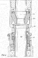
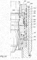
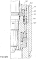
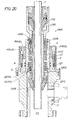
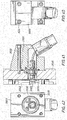
- FIG. 2 is a cross-section view of an embodiment of a single diverter housing section, riser section, or other applicable wellbore tubular section (hereinafter a "housing section"), and a single hydraulic latch assembly to better illustrate the rotating control device 100 of FIG. 1 .
- a latch assembly separately indicated at 210 is bolted to a housing section 200 with bolts 212A and 212B. Although only two bolts 212A and 212B are shown in FIG. 2 , any number of bolts and any desired arrangement of bolt positions can be used to provide the desired securement and sealing of the latch assembly 210 to the housing section 200 .
- FIG. 2 is a cross-section view of an embodiment of a single diverter housing section, riser section, or other applicable wellbore tubular section (hereinafter a "housing section"), and a single hydraulic latch assembly to better illustrate the rotating control device 100 of FIG. 1 .
- a latch assembly separately indicated at 210 is bolted to a housing section 200 with bolts 212
- the housing section 200 has a single outlet 202 for connection to a diverter conduit 204 , shown in phantom view; however, other numbers of outlets and conduits can be used, as shown, for example, in the dual diverter embodiment of FIG. 1 with diverter conduits 115 and 117 . Again, this conduit 204 can be connected to a choke.
- the size, shape, and configuration of the housing section 200 and latch assembly 210 are exemplary and illustrative only, and other sizes, shapes, and configurations can be used to allow connection of the latch assembly 210 to a riser.
- the hydraulic latch assembly is shown connected to a nipple, the latch assembly can be connected to any conveniently configured section of a wellbore tubular or riser.
- a landing formation 206 of the housing section 200 engages a shoulder 208 of the rotating control device 100 , limiting downhole movement of the rotating control device 100 when positioning the rotating control device 100 .
- the relative position of the rotating control device 100 and housing section 200 and latching assembly 210 are exemplary and illustrative only, and other relative positions can be used.
- FIG. 2 shows the latch assembly 210 latched to the rotating control device 100 .
- a retainer member 218 extends radially inwardly from the latch assembly 210 , engaging a latching formation 216 in the rotating control device 100 , latching the rotating control device 100 with the latch assembly 210 and therefore with the housing section 200 bolted with the latch assembly 210 .
- the retainer member 218 can be "C-shaped", such as retainer ring 275 in FIG. 2B , that can be compressed to a smaller diameter for engagement with the latching formation 216 .
- retainer rings are contemplated.
- the retainer member 218 can be a plurality of dog, key, pin, or slip members, spaced apart and positioned around the latch assembly 210 , as illustrated by dog members 250A, 250B , 250C , 250D , 250E , 250F , 250G , 250H , and 250I in FIG. 2A .
- the retainer member 218 is a plurality of dog or key members
- the dog or key members can optionally be spring-biased.
- the number, shape, and arrangement of dog members 250 illustrated in FIG. 2A is illustrative and exemplary only, and other numbers, arrangements, and shapes can be used. Although a single retainer member 218 is described herein, a plurality of retainer members 218 can be used.
- the retainer member 218 has a cross section sufficient to engage the latching formation 216 positively and sufficiently to limit axial movement of the rotating control device 100 and still engage with the latch assembly 210 .
- An annular piston 220 is shown in a first position in Figure 2 , in which the piston 220 blocks the retainer member 218 in the radially inward position for latching with the rotating control device 100 . Movement of the piston 220 from a second position to the first position compresses or moves the retainer member 218 radially inwardly to the engaged or latched position shown in FIG. 2 .
- the piston 220 can be implemented, for example, as a plurality of separate pistons disposed about the latch assembly 210 .
- the retainer member 218 when the piston 220 moves to a second position, the retainer member 218 can expand or move radially outwardly to disengage from and unlatch the rotating control device 100 from the latch assembly 210 .
- the retainer member 218 and latching formation 216 ( FIG. 2 ) or 320 ( FIG. 6 ) can be formed such that a predetermined upward force on the rotating control device 100 will urge the retainer member radially outwardly to unlatch the rotating control device 100 .
- a second or auxiliary piston 222 can be used to urge the first piston 220 into the second position to unlatch the rotating control device 100 , providing a backup unlatching capability.
- the shape and configuration of pistons 220 and 222 are exemplary and illustrative only, and other shapes and configurations can be used.
- hydraulic ports 232 and 234 and corresponding gun-drilled passageways allow hydraulic actuation of the piston 220 .
- Increasing the relative pressure on port 232 causes the piston 220 to move to the first position, latching the rotating control device 100 to the latch assembly 210 with the retainer member 218 .
- Increasing the relative pressure on port 234 causes the piston 220 to move to the second position, allowing the rotating control device 100 to unlatch by allowing the retainer member 218 to expand or move and disengage from the rotating control device 100 .
- Connecting hydraulic lines (not shown in the figure for clarity) to ports 232 and 234 allows remote actuation of the piston 220 .
- the second or auxiliary annular piston 222 is also shown as hydraulically actuated using hydraulic port 230 and its corresponding gun-drilled passageway. Increasing the relative pressure on port 230 causes the piston 222 to push or urge the piston 220 into the second or unlatched position, should direct pressure via port 234 fail to move piston 220 for any reason.
- the hydraulic ports 230, 232 and 234 and their corresponding passageways shown in FIG. 2 are exemplary and illustrative only, and other numbers and arrangements of hydraulic ports and passageways can be used.
- other techniques for remote actuation of pistons 220 and 222 other than hydraulic actuation, are contemplated for remote control of the latch assembly 210 .
- the rotating control device illustrated in FIG. 2 can be positioned, latched, unlatched, and removed from the housing section 200 and latch assembly 210 without sending personnel below the rotary table into the moon pool to manually connect and disconnect the rotating control device 100 .
- each piston 220 preferably has an inner and outer seal to allow fluid pressure to build up and force the piston in the direction of the force.
- seals can be used to seal the joints and retain the fluid from leaking between various components. In general, these seals will not be further discussed herein.
- seals 224A and 224B seal the rotating control device 100 to the latch assembly 210 .
- seals 224A and 224B are shown in FIG. 2 , any number and arrangement of seals can be used.
- seals 224A and 224B are Parker Polypak® 0.6cm (1 ⁇ 4-inch) cross section seals from Parker Hannifin Corporation. Other seal types can be used to provide the desired sealing.
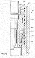
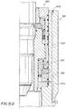
- FIG. 3 illustrates a second embodiment of a latch assembly, generally indicated at 300 , that is a dual hydraulic latch assembly.
- piston 220 compresses or moves retainer member 218 radially inwardly to latch the rotating control device 100 to the latch assembly 300 .
- the retainer member 218 latches the rotating control device 100 in a latching formation, shown as an annular groove 320 , in an outer housing of the rotating control device 100 in FIG. 3 .
- the use and shape of annular groove 320 is exemplary and illustrative only and other latching formations and formation shapes can be used.
- the dual hydraulic latch assembly includes the pistons 220 and 222 and retainer member 218 of the single latch assembly embodiment of FIG. 2 as a first latch subassembly.
- the various embodiments of the dual hydraulic latch assembly discussed below as they relate to the first latch subassembly can be equally applied to the single hydraulic latch assembly of FIG. 2 .
- the dual hydraulic latch assembly 300 embodiment illustrated in FIG. 3 provides a second latch subassembly comprising a third piston 302 and a second retainer member 304 .
- the latch assembly 300 is itself latchable to a housing section 310 , shown as a riser nipple, allowing remote positioning and removal of the latch assembly 300 .
- the housing section 310 and dual hydraulic latch assembly 300 are preferably matched with each other, with different configurations of the dual hydraulic latch assembly implemented to fit with different configurations of the housing section 310 .
- a common embodiment of the rotating control device 100 can be used with multiple dual hydraulic latch assembly embodiments; alternately, different embodiments of the rotating control device 100 can be used with each embodiment of the dual hydraulic latch assembly 300 and housing section 310 .
- the piston 302 moves to a first or latching position.
- the retainer member 304 instead expands radially outwardly, as compared to inwardly, from the latch assembly 300 into a latching formation 311 in the housing section 310 .
- the latching formation 311 can be any suitable passive formation for engaging with the retainer member 304 .
- the shape and configuration of piston 302 is exemplary and illustrative only and other shapes and configurations of piston 302 can be used.
- the retainer member 304 can be "C-shaped", such as retainer ring 275 in FIG.
- the retainer member 304 can be a plurality of dog, key, pin, or slip members, positioned around the latch assembly 300 .
- the retainer member 304 is a plurality of dog or key members
- the dog or key members can optionally be spring-biased.
- a single retainer member 304 is described herein, a plurality of retainer members 304 can be used.
- the retainer member 304 has a cross section sufficient to engage positively the latching formation 311 to limit axial movement of the latch assembly 300 and still engage with the latch assembly 300 .
- the latch assembly 300 can be manufactured for use with a specific housing section, such as housing section 310 , designed to mate with the latch assembly 300 .
- the latch assembly 210 of FIG. 2 can be manufactured to standard sizes and for use with various generic housing sections 200 , which need no modification for use with the latch assembly 210 .
- Cables can be connected to eyelets or rings 322A and 322B mounted on the rotating control device 100 to allow positioning of the rotating control device 100 before and after installation in a latch assembly.
- the use of cables and eyelets for positioning and removal of the rotating control device 100 is exemplary and illustrative, and other positioning apparatus and numbers and arrangements of eyelets or other attachment apparatus, such as discussed below, can be used.
- the latch assembly 300 can be positioned in the housing section 310 using cables (not shown) connected to eyelets 306A and 306B , mounted on an upper surface of the latch assembly 300 . Although only two such eyelets 306A and 306B are shown in FIG. 3 , other numbers and placements of eyelets can be used. Additionally, other techniques for mounting cables and other techniques for positioning the unlatched latch assembly 300 , such as discussed below, can be used. As desired by the operator of a rig, the latch assembly 300 can be positioned or removed in the housing section 310 with or without the rotating control device 100 .
- the latched rotating control device 100 and latch assembly 300 can be unlatched from the housing section 310 and removed as a unit for repair or replacement.
- a shoulder of a running tool, tool joint 260A of a string 260 of pipe, or any other shoulder on a tubular that could engage lower stripper rubber 246 can be used for positioning the rotating control device 100 instead of the above-discussed eyelets and cables.
- An exemplary tool joint 260A of a string of pipe 260 is illustrated in phantom in FIG. 2 .
- the rotating control device 100 includes a bearing assembly 240 .
- the bearing assembly 240 is similar to the Weatherford-Williams model 7875 rotating control device, now available from Weatherford International, Inc., of Houston, Texas.
- Weatherford-Williams models 7000, 7100, IP-1000, 7800, 8000/9000, and 9200 rotating control devices or the Weatherford RPM SYSTEM 3000TM, now available from Weatherford International, Inc. could be used.
- a rotating control device 240 with two spaced-apart seals, such as stripper rubbers, is used to provide redundant sealing.
- the major components of the bearing assembly 240 are described in US Patent No.
- the bearing assembly 240 includes a top rubber pot 242 that is sized to receive a top stripper rubber or inner member seal 244 ; however, the top rubber pot 242 and seal 244 can be omitted, if desired.
- a bottom stripper rubber or inner member seal 246 is connected with the top seal 244 by the inner member of the bearing assembly 240 .
- the outer member of the bearing assembly 240 is rotatably connected with the inner member.
- the seals 244 and 246 can be passive stripper rubber seals, as illustrated, or active seals as known by those of ordinary skill in the art.
- the lower accumulator 510 as shown in FIG. 5 is required, because hoses and lines cannot be used to maintain hydraulic fluid pressure in the bearing assembly 100 lower portion.
- the accumulator 510 allows the bearings (not shown) to be self-lubricating.
- An additional accumulator 410 can be provided in the upper portion of the bearing assembly 100 if desired.
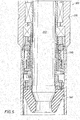
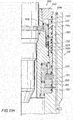
- FIG. 6 an enlarged cross-section view illustrates one side of the latch assembly 300 .
- Both the first retainer member 218 and the second retainer member 304 are shown in their unlatched position, with pistons 220 and 302 in their respective second, or unlatched, position.
- Sections 640 and 650 form an outer housing for the latch assembly 300
- sections 620 and 630 form an inner housing, illustrated in Figure 6 as threadedly connected to the outer housing 640 and 650 .
- Other types of connections can be used to connect the inner housing and outer housing of the latch assembly 300 .
- the number, shape, relative sizes, and structural interrelationships of the sections 620 , 630 , 640 and 650 are exemplary and illustrative only and other relative sizes, numbers, shapes, and configurations of-sections, and arrangements of sections can be used to form inner and outer housings for the latch assembly 300 .
- the inner housings 620 and 630 and the outer housings 640 and 650 form chambers 600 and 610 , respectively.
- Pistons 220 and 222 are slidably positioned in chamber 600 and piston 302 is slidably positioned in chamber 610 .
- the relative size and position of chambers 600 and 610 are exemplary and illustrative only.
- some embodiments of the latch assembly 300 can have the relative position of chambers 610 and 600 reversed, with the first latch subassembly of pistons 220 , 222 , and retainer member 218 being lower (relative to FIG. 6 ) than the second latch subassembly of piston 302 and retainer member 304 .
- the piston 220 is axially aligned in an offset manner from the retainer member 218 by an amount sufficient to engage a tapered surface 604 on the outer periphery of the retainer member 218 with a corresponding tapered surface 602 on the inner periphery of the piston 220 .
- the force exerted between the tapered surfaces 602 and 604 compresses the retainer member 218 radially inwardly to engage the groove 320 .
- the piston 302 is axially aligned in an offset manner from the retainer member 304 by an amount sufficient to engage a tapered surface 614 on the inner periphery of the retainer member 304 with a corresponding tapered surface 612 on the outer periphery of the piston 302 .
- the force exerted between the tapered surfaces 612 and 614 expands the retainer member 304 radially outwardly to engage the groove 311 .
- piston 302 for urging piston 302 similar to the second or auxiliary piston 222 used to disengage the rotating control device from the latch assembly 300 , it is contemplated that an auxiliary piston (not shown) to urge piston 302 from the first, latched position to the second, unlatched position could be used, if desired.
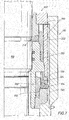
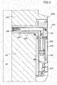
- FIGS. 6 to 8 illustrate the latch assembly 300 in three different positions.
- both the retainer members 218 and 304 are in their retracted or unlatched position.
- Hydraulic fluid pressure in passageways 660 and 670 (the port for passageway 670 is not shown) move pistons 220 and 302 upward relative to the figure, allowing retainer member 218 to move radially outwardly and retainer member 304 to move radially inwardly to unlatch the rotating control device 100 from the latch assembly 300 and the latch assembly 300 from the housing section 310 .
- the passageways 660, 670, 710, 720, and 810 that traverse the latch assembly 300 and the housing section 310 connect to ports on the side of the housing section 310 .
- other positions for the connection ports can be used, such as on the top surface of the riser nipple as shown in FIG. 2 , with corresponding redirection of the passageways 660, 670, 710, 720, and 810 without traversing the housing section 310 . Therefore, the position of the hydraulic ports and corresponding passageways shown in FIGS. 6 to 8 are illustrative and exemplary only, and other hydraulic ports and passageways and location of ports and passageways can be used.
- FIGS. 6 to 8 show the passageways 660 , 670 , 710, 720, and 810 traversing the latch assembly 300 and housing section 310 , the passageways can be contained solely within the latch assembly 300 .
- FIG. 7 shows both retainer members 218 and 304 in their latched position. Hydraulic pressure in passageway 710 (port not shown) and 720 move pistons 220 and 302 to their latched position, urging retainer members 218 and 304 to their respective latched positions.
- FIG. 8 shows use of the auxiliary or secondary piston 222 to urge or move the piston 220 to its second, unlatched position, allowing radially outward expansion of retainer member 218 to unlatch the rotating control device 100 from the latch assembly 300 .
- Hydraulic passageway 810 provides fluid pressure to actuate the piston 222 .
- FIGS. 6 to 8 illustrate the retainer member 218 and the retainer member 304 with both retainer members 218 and 304 being latched or both retainer members 218 and 304 being unlatched
- operation of the latch assembly 300 can allow retainer member 218 to be in a latched position while retainer member 304 is in an unlatched position and vice versa.
- This variety of positioning is achieved since each of the hydraulic passageways 660 , 670 , 710 , 720, and 810 can be selectively and separately pressurized.
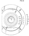
- a pressure transducer protector assembly attached to a sidewall of the housing section 310 protects a pressure transducer 950 .
- a passage 905 extends through the sidewall of the housing section 310 between a wellbore W or an inward surface of the housing section 310 to an external surface 310A of the housing section 310 .
- a housing for the pressure transducer protector assembly 900 comprises sections 902 and 904 in the exemplary embodiment illustrated in FIG. 9 . Section 904 extends through the passage 905 of the housing section 310 to the wellbore W , positioning a conventional diaphragm 910 at the wellbore end of section 904 .
- a bore or chamber 920 formed interior to section 904 provides fluid communication from the diaphragm 910 to a pressure transducer 950 mounted in chamber 930 of section 902 .
- Sections 902 and 904 are shown bolted to each other and to the housing section 310 , to form the pressure transducer protector assembly 900 .
- Other ways of connecting sections 902 and 904 to each other and to the housing section 310 or other housing section can be used.
- the pressure transducer protector assembly 900 can be unitary, instead of comprising the two sections 902 and 904 .
- Other shapes, arrangements, and configurations of sections 902 and 904 can be used.
- Pressure transducer 950 is a conventional pressure transducer and can be of any suitable type or manufacture. In one embodiment, the pressure transducer 950 is a sealed gauge pressure transducer. Additionally, other instrumentation can be inserted into the passage 905 for monitoring predetermined characteristics of the wellbore W .
- a plug 940 allows electrical connection to the transducer 950 for monitoring the pressure transducer 950 . Electrical connections between the transducer 950 and plug 940 and between the plug 940 to an external monitor are not shown for clarity of the figure.
- FIGS. 10A and 10B illustrate two alternate embodiments of the pressure transducer protector assembly 900 and illustrate an exemplary placement of the pressure transducer protector assembly 900 in the housing section 310 .
- the placement of the pressure transducer protector assembly 900 in FIGS. 10A and 10B is exemplary and illustrative only, and the assembly 900 can be placed in any suitable location of the housing section 310.
- the assembly 900A of FIG. 10A differs from the assembly 900B of FIG. 10B only in the length of the section 904 and position of the diaphragm 910 .
- FIG. 10A differs from the assembly 900B of FIG. 10B only in the length of the section 904 and position of the diaphragm 910 .
- the section 904A extends all the way through the housing section 310 , placing the diaphragm 910 at the interior or wellbore W surface of the housing section 310 .
- the alternate embodiment of FIG. 10B instead limits the length of section 904B, placing the diaphragm 910 at the exterior end of a bore 1000 formed in the housing section 310 .
- the alternate embodiments of FIGS. 10A and 10B are exemplary only and other section 904 lengths and diaphragm 910 placements can be used, including one in which diaphragm 910 is positioned interior to the housing section 310 at the end of a passage similar to passage 1000 extending part way through the housing section 310.
- the wellbore pressure measured by pressure transducer 950 can be used to protect against unlatching the selected latching assembly 300 if the wellbore pressure is above a predetermined amount.
- One value contemplated for the predetermined wellbore pressure is a range of above 1.4x10 5 -2.1x10 5 Pa (20-30 PSI).
- the pressure transducer protector assembly 900 can be used with the single hydraulic latch assembly 210 of FIG. 2 .
- FIGS. 11A-17 illustrate various alternate embodiments for a latch position indicator system that can allow a system or rig operator to determine remotely whether the dual hydraulic latch assembly 300 is latched or unlatched to the housing section, such as housing section 310 , and the rotating control device 100 .
- FIGS. 11A-17 are configured for the dual hydraulic latch assembly 300 , one skilled in the art would recognize that the relevant portions of the latch position indicator system can also be used with the single hydraulic latch assembly 210 of FIG. 2 , using only those elements related to latching the latch assembly to the rotating control device 100 .
- hydraulic lines provide fluid to the latch assembly 300 for determining whether the latch assembly 300 is latched or unlatched from the rotating control device 100 and the housing section 310 . Hydraulic lines also provide fluid to the latch assembly 300 to move the pistons 220 , 222 , and 302 .
- hydraulic fluid is provided from a fluid source (not shown) through a hydraulic line (not shown) to ports, best shown in FIG. 12 . Passageways internal to the housing section 310 and latch assembly 300 communicate the fluid to the pistons 220 , 222 , and 302 for moving the pistons 220 , 222 , and 302 between their unlatched and latched positions.
- passageways internal to the housing section 310 and latch assembly 300 communicate the fluid to the pistons 220 , 222 , and 302 for the latch position indicator system.
- Channels are formed in a surface of the pistons 220 and 302 . As illustrated in FIGS. 11A-11H , these channels in an operating orientation are substantially horizontal grooves that traverse a surface of the pistons 220 and 302 . If piston 220 or 302 is in the latched position, the channel aligns with at least two of the passageways, allowing a return passageway for the hydraulic fluid. As described below in more detail with respect to FIG. 13 , a hydraulic fluid pressure in the return line can be used to indicate whether the piston 220 or 302 is in the latched or unlatched position.
- a hydraulic fluid pressure will indicate that the channel is providing fluid communication between the input hydraulic line and the return hydraulic line. If the piston 220 or 302 is in the unlatched position, the channel is not aligned with the passageways, producing a lower pressure on the return line. As described below in more detail, the pressure measurement could also be on the input line, with a higher pressure indicating nonalignment of the channel and passageways, hence the piston 220 or 302 is in the unlatched position, and a lower pressure indicating alignment of the channel and passageways, hence the piston 220 or 302 is in the latched position. As described below in more detail, a remote latch position indicator system can use these pressure values to cause indicators to display whether the pistons 220 and 302 are latched or unlatched.
- the passageways are holes formed by drilling the applicable element, sometimes known as "gun-drilled holes.” More than one drilling can be used for passageways that are not a single straight passageway, but that make turns within one or more element. However, other techniques for forming the passageways can be used.
- the positions, orientations, and relative sizes of the passageways illustrated in FIGS. 11A-11H are exemplary and illustrative only and other position, orientations, and relative sizes can be used.
- FIGS. 11A-11H are illustrated as grooves, but any shape or configuration of channel can be used as desired.
- the positions, shape, orientations, and relative sizes of the channels illustrated in FIGS. 11A-11H are exemplary and illustrative only and other position, orientations, and relative sizes can be used.
- passageway 1101 formed in housing section 310 provides fluid communication from a hydraulic line (not shown) to the latch assembly 300 to provide hydraulic fluid to move piston 220 from the unlatched position to the latched position.
- a passageway 1103 formed in outer housing element 640 communications passageway 1101 and the chamber 600 , allowing fluid to enter the chamber 600 and move piston 220 to the latched position.
- Passageway 1103 may actually be multiple passageways in multiple radial-slices of latch assembly 300 , as illustrated in FIGS.
- passageway 1104 is formed in outer housing element 640 , which communicates with a channel 1102 formed on a surface of piston 220 when piston 220 is in the latched position.
- the passageway 1104 does not directly communicate with a hydraulic line input or return passageway in the housing section 310
- a plurality of passageways 1104 in the various slices of FIGS. 11A-11H are in fluid communication with each other via the channel 1102 when the piston 220 is in the latched position.
- Another plurality of passageways 1105 formed in outer housing element 640 provides fluid communication to chamber 600 between piston 220 and piston 222 . Fluid pressure in chamber 600 through passageway 1105 urges piston 220 into the unlatched position, and moves piston 222 away from piston 220. Yet another plurality of passageways 1107 formed in outer housing element 640 provides fluid communication to chamber 600 such that fluid pressure urges piston 222 towards piston 220 , and can, once piston 222 contacts piston 220, cause piston 220 to move into the unlatched position as an auxiliary or backup way of unlatching the latch assembly 300 from the rotating control device 100 , should fluid pressure via passageway 1105 fail to move piston 220 . Although as illustrated in FIG.
- pistons 220 and 222 are in contact with each other when piston 220 is in the latched position, pistons 220 and 222 can be separated by a gap between them when the piston 220 is in the latched position, depending on the size and shape of the pistons 220 and 222 and the chamber 600 .
- a passageway 1100 is formed in outer housing element 640 . This passageway forms a portion of passageway 1112 described below with respect to FIG. 11C .
- passageway 1104 is further in fluid communication with passageway 1106 formed in housing section 310 , which can be connected with a hydraulic line for supply or return of fluid to the latch assembly 300 . If passageway 1106 is connected to a supply line, then hydraulic fluid input through passageway 1106 traverses passageway 1104 and channel 1102 , then returns via passageways 1108 and 1110 to a return hydraulic line, as shown in FIG. 11C .
- passageway 1106 If passageway 1106 is connected to a return line, then hydraulic fluid input through passageways 1108 and 1110 traverses the channel 1102 to return via passageways 1104 and 1106 to the return line. Because fluid communication between passageways 1106 and 1108 is interrupted when piston 220 moves to the unlatched position, as shown in FIG. 11C , pressure in the line (supply or return) connected to passageway 1106 can indicate the position of piston 220 . For example, if passageway 1106 is connected to a supply hydraulic line, a measured pressure value in the supply line above a predetermined pressure value will indicate that the piston 220 is in the unlatched position. Alternately, if passageway 1106 is connected to a return hydraulic line, a measured pressure value in the return line below a predetermined pressure value will indicate that the piston 220 is in the unlatched position.
- FIG. 11C illustrates a passageway 1108 in housing section 310 that is in fluid communication with passageway 1110 in outer housing element 640 of the latch assembly 300 .
- passageways 1108 and 1106 are in fluid communication with each other, via passageways 1104 and 1110, together with channel 1102 and are not in fluid communication when piston 220 is in the unlatched position.
- passageway 1108 is in fluid communication with passageway 1112.
- FIG. 11C and FIG. 11F when piston 302 is in the latched position, as shown in FIG. 11F , passageway 1112 is in fluid communication with passageways 1116 and 1118 via channel 1114 formed in piston 302 .
- passageway 1108 is connected to a hydraulic supply line, then if the measured pressure value in the supply line exceeds a predetermined pressure value, piston 302 is in the unlatched position, and if the measured pressure value in the supply line is below a predetermined pressure value, piston 302 is in the unlatched position.
- passageway 1108 is connected to a hydraulic return line, if the measured pressure value in the return line is equal to or above a predetermined pressure value, then piston 302 is in the latched position, and if the pressure in the return line is equal to or less than a predetermined pressure value, then piston 302 is in the unlatched position.
- passageway 1109 in the housing section 310 can provide hydraulic fluid through passageway 1105 in the latch assembly 300 to chamber 600 , urging piston 220 from the latched position to the unlatched position, as well as to move piston 222 away from piston 220 .
- passageway 1111 in the housing section 310 can provide hydraulic fluid through passageway 1107 in the latch assembly 300 , urging piston 222 , providing a backup technique for moving piston 220 from the latched position into the unlatched position, once piston 222 contacts piston 220 .
- FIG. 11E passageway 1111 in the housing section 310 can provide hydraulic fluid through passageway 1107 in the latch assembly 300 , urging piston 222 , providing a backup technique for moving piston 220 from the latched position into the unlatched position, once piston 222 contacts piston 220 .
- hydraulic fluid in passageway 1117 in the housing section 310 traverses passageway 1119 to enter chamber 610 , moving piston 302 from the unlatched position to the latched position, while hydraulic fluid in passageway 1121 in the housing section 310 , illustrated in FIG. 11H , traverses passageway 1123 to enter chamber 610 , moving piston 302 from the latched position to the unlatched position.
- fluid can also exit from the chambers when the piston is moved, depending on the direction of the move.
- pumping fluid through passageways 1101 and 1103 into chamber 600 can cause fluid to exit chamber 600 via passageways 1105 and 1109, while pumping fluid through passageways 1109 and 1105 into chamber 600 can cause fluid to return from chamber 600 via passageways 1103 and 1101, as the piston 220 moves within chamber 600 .
- port 1210 is connected to passageway 1101
- port 1220 is connected to passageway 1106
- port 1230 is connected to passageway 1108
- port 1240 is connected to passageway 1109
- port 1250 is connected to passageway 1111
- port 1260 is connected to passageway 1118
- port 1270 is connected to passageway 1117
- port 1280 is connected to passageway 1121 .
- the arrangement of ports and order of the slices illustrated in FIGS. 11A-11H is exemplary and illustrative only, and other orders and arrangements of ports can be used.
- the placement of ports 1210 to 1280 illustrated in end view in FIG. 12 is exemplary only, and other locations for the ports 1210 to 1280 can be used, such as discussed above on the side of the housing section 310 , as desired.
- FIG. 12 illustrates eyelets that can be used to connect cables or other equipment to the housing section 310 and latch assembly 300 for positioning the housing section 310 and latch assembly 300 .
- the housing section 310 and latch assembly 300 can be latched and unlatched from each other and to the rotating control device 100 remotely using hydraulic line connected to ports 1210 , 1240 , 1250 , 1270 , and 1280 , the housing section 310 , the latch assembly 300 and the rotating control device 100 can be latched to or unlatched from each other and repositioned as desired without sending personnel below the rotary table 130 .
- ports 1220 , 1230 , and 1260 can provide supply and return lines to a remote latch position indicator system, an operator of the rig does not need to send personnel below the rotary table 130 to determine the position of the latch assembly 300 , but can do so remotely.
- the hydraulic latch position indicator system may be used with a secondary or back-up piston to determine its position, and therefore to indirectly determine the position of the retainer member. Further, it is contemplated that the hydraulic latch position indicator system may also be used with the retainer member to directly determine its position.
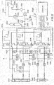
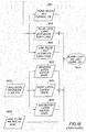
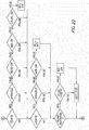
- FIG. 13 a schematic diagram for an alternate embodiment of a system S for controlling the latch assembly 300 of FIGS. 6 to 8 , including a latch position indicator system for remotely indicating the position of the latch assembly 300 .
- the elements of FIG. 13 represent functional characteristics of the system S rather than actual physical implementation, as is conventional with such schematics.
- Block 1400 represents a remote control display for the latch position indicator subsystem of the system S , and is further described in one embodiment in FIG. 14 .
- Control lines 1310 connect pressure transducers ( PT ) 1340, 1342, 1344, 1346, and 1348 and flow meters ( FM ) 1350 , 1352 , 1354 , 1356 , 1358 , and 1360 .
- the flow meters FM may be totalizing flow meters, gear flow meters or a combination of these meters or other meters.
- One gear meter is an oval-gear meter having two rotating, oval-shaped gears with synchronized, close fitting teeth. When a fixed quantity of liquid passes through the meter for each revolution, shaft rotation can be monitored to obtain specific flow rates.
- the flow meters FM may be turbine flow meters. However, other types of flow meters FM are contemplated to fit the particular application of the system. Also, if desired flow conditioners, such as those disclosed in US Pat. Nos. 5,529,093 and 5,495,872 could be used.
- a programmable logic controller or other similar measurement and control device, either at each pressure transducer PT and flow meter FM or remotely in the block 1400 reads an electrical output from the pressure transducer PT or flow meter FM and converts the output into a signal for use by the remote control display 1400 , possibly by comparing a flow value or pressure value measured by the flow meter FM or pressure transducer PT to a predetermined flow value or pressure value, controlling the state of an indicator in the display 1400 according to a relative relationship between the measured value and the predetermined value.
- PLC programmable logic controller
- the display 1400 may indicate one state of the flow meter FM or corresponding device, and if the measured flow value is greater than a predetermined value, the display 1400 may indicate another state of the flow meter FM or corresponding device.
- a fluid supply subsystem 1330 provides a controlled hydraulic fluid pressure to a fluid valve subsystem 1320 .
- the fluid supply subsystem 1330 includes shutoff valves 1331A and 1331B , reservoirs 1332A and 1332B , an accumulator 1333 , a fluid filter 1334 , a pump 1335, pressure relief valves 1336 and 1337 , a gauge 1338 , and a check valve 1339 , connected as illustrated.
- the fluid supply subsystem 1330 illustrated in FIG. 13 can be any convenient fluid supply subsystem for supplying hydraulic fluid at a controlled pressure.
- a fluid valve subsystem 1320 controls the provision of fluid to hydraulic fluid lines (unnumbered) that connect to the chambers 1370 , 1380 and 1390 .
- FIG. 13 illustrates the subsystem 1320 using three directional valves 1324 , 1325 and 1326 , each connected to one of reservoirs 1321 , 1322 and 1323 .
- Each of the valves 1324 , 1325 , and 1326 are illustrated as three-position, four-way electrically actuated hydraulic valves. Valves 1325 and 1326 , respectively, can be connected to pressure relief valves 1328 and 1329 .
- the elements of the fluid valve subsystem 1320 as illustrated in FIG. 13 are exemplary and illustrative only, and other components, and numbers, arrangements, and connections of components can be used as desired.
- Pressure transducers PT or other pressure measuring devices 1340 , 1342 , 1344 , 1346 and 1348 measure the fluid pressure in the hydraulic lines between the fluid valve subsystem 1320 and the chambers 1370 , 1380 and 1390 .
- Control lines 1310 connect the pressure measuring devices 1340 , 1342 , 1344 , 1346 and 1348 to the remote control display 1400 .
- flow meters FM 1350 , 1352 , 1354 , 1356 , 1358 and 1360 measure the flow of hydraulic fluid to the meters FM 1350 , 1352 , 1354 , 1356 , 1358 and 1360 measure the flow of hydraulic fluid to the chambers 1370-1390 , which can allow measuring the volume of fluid that is delivered to the chambers 1370 , 1380 and 1390 .
- the system S includes both pressure transducers PT and flow meters FM , either the pressure transducers PT or the flow meters FM can be omitted if desired.
- pressure transducers PT and flow meters FM other types of pressure and flow measuring devices can be used as desired.
- FIG. 14 an exemplary indicator panel is illustrated for remote control display 1400 for the system S of FIG. 13 .
- switch will be used to indicate any type of control that can be activated or deactivated, without limitation to specific types of controls. Exemplary switches are toggle switches and push buttons, but other types of switches can be used.
- Pressure gauges 1402 , 1404 , 1406 , and 1408 connected by control lines 1310 to the pressure transducers, such as the pressure transducers PT of FIG. 13 indicate the pressure in various parts of the system S . Indicators on the panel include wellbore pressure gauge 1402 , bearing latch pressure gauge 1404 , pump pressure gauge 1406 , and body latch pressure gauge 1408 .
- the rotating control device or bearing latch pressure 1404 indicates the pressure in the chamber 600 at the end of the chamber where fluid is introduced to move the piston 220 into the latched position.
- the housing section or body latch pressure gauge 1408 indicates the pressure in the chamber 610 at the end of the chamber where fluid is introduced to move the piston 302 into the latched position.
- a switch or other control 1420 can be provided to cause the system S to manipulate the fluid valve subsystem 1320 to move the piston 302 between the latched (closed) and unlatched (open) positions.
- the body latch control 1420 is preferably protected with a switch cover 1422 or other apparatus for preventing accidental manipulation of the control 1420 .
- an enable switch 1410 can be similarly protected by a switch cover 1412 .
- the enable switch 1410 must be simultaneously or closely in time engaged with any other switch, except the Off/On control 1430 to enable the other switch.
- engaging the enable switch allows activation of other switches within 10 seconds of engaging the enable switch. This technique helps prevent accidental unlatching or other dangerous actions that might otherwise be caused by accidental engagement of the other switch.
- An Off/On control 1430 controls the operation of the pump 1335 .
- a Drill Nipple/Bearing Assembly control 1440 controls a pressure value produced by the pump 1335 .
- the pressure value can be reduced if a drilling nipple or other thin walled apparatus is installed.
- the pump 1335 can pressurize the fluid to 1.4MPa (200 PSI), but when the control is in the "Bearing Assembly” position, the pump 1335 can pressurize the fluid to 6.9MPa (1000 PSI).
- an "Off' position can be provided to set the pump pressure to 0 Pa (0 PSI). Other fluid pressure values can be used.
- the "Bearing Assembly" position can cause pressurization depending on the position of the Bearing Latch switch 1450, such as 5.5MPa (800 PSI) if switch 1450 is closed and 13.8 MPa (2000 PSI) if switch 1450 is open.
- Control 1450 controls the position of the piston 220 , latching the rotating control device 100 to the latch assembly 300 in the "closed” position by moving the piston 220 to the latched position.
- the control 1460 controls the position of the auxiliary or secondary piston 222 , causing the piston 222 to move to urge the piston 220 to the unlatched position when the bearing latch control 1460 is in the "open” position.
- Indicators 1470 , 1472 , 1474 , 1476 , 1478 , 1480 , 1482 , 1484 , 1486 , and 1488 provide indicators of the state of the latch assembly and other useful indicators. As illustrated in FIG. 14 , the indicators are single color lamps, which illuminate to indicate the specific condition.
- indicators 1472 , 1474 , 1476 , and 1478 are green lamps, while indicators 1470 , 1480 , 1482 , 1484 , 1486 , and 1488 are red lamps; however, other colors can be used as desired.
- Other types of indicators can be used as desired, including multicolor indicators that combine the separate open/closed indicators illustrated in FIG. 14 .
- Such illuminated indicators are known to the art.
- Indicator 1470 indicates whether the hydraulic pump 1335 of FIG. 13 is operating.
- indicators 1472 and 1482 indicate whether the bearing latch is closed or open, respectively, corresponding to the piston 220 being in the latched or unlatched position, indicating the rotating control device 100 is latched to the latch assembly 300 .
- Indicators 1474 and 1484 indicate whether the auxiliary or secondary latch is closed or open, respectively, corresponding to the piston 222 being in the first or second position.
- Indicators 1476 and 1486 indicate whether the body latch is closed or open, respectively, i.e., whether the latch assembly 300 is latched to the housing section 310 , corresponding to whether the piston 302 is in the unlatched or latched positions.
- hydraulic fluid indicators 1478 and 1488 indicate low fluid or fluid leak conditions, respectively.
- An additional alarm indicator indicates various alarm conditions. Some exemplary alarm conditions include: low fluid, fluid leak, pump not working, pump being turned off while wellbore pressure is present and latch switch being moved to open when wellbore pressure is greater than a predetermined value, such as 0.17MPa (25 PSI).
- a horn (not shown) can be provided for an additional audible alarm for safety purposes.
- the display 1400 allows remote control of the latch assembly 210 and 300, as well as remote indication of the state of the latch assembly 210 and 300 , as well as other related elements.
- FIG. 18 illustrates an exemplary set of conditions that can cause the alarm indicator 1480 and horn to be activated.
- blocks 1830 and 1840 if any of the flow meters FM of FIG. 13 indicate greater than a predetermined flow rate, illustrated in FIG. 18 as 3 GPM, then both the alarm light 1480 and the horn will be activated.
- blocks 1820 , 1822 , 1824 , 1826 , and 1840 if the wellbore pressure is in a predetermined relative relation to a predetermined pressure value, illustrated in FIG.
- both the alarm 1480 and horn are activated. Additionally, as indicated by blocks 1810 , 1811 , 1812 , 1813 , and 1850 , if the wellbore pressure is in a predetermined relative relationship to a predetermined pressure value, illustrated in FIG. 18 as greater than 0.17MPa (25 PSI), and either the body latch switch 1420 is open, the bearing latch switch 1450 is open, or the secondary latch switch 1460 is open, then the alarm indicator 1480 is activated, but the horn is not activated.
- the conditions that cause activation of the alarm 1480 and horn of FIG. 18 are illustrative and exemplary only, and other conditions and combinations of conditions can cause the alarm 1480 or horn to be activated.
- FIGS. 15K , 15L , 15M , 15N , 15O and 16 illustrate an embodiment in which measurement of the volume of fluid pumped into chambers 600 and 610 can be used to indicate the state of the latch assembly 300 .
- Passageways 1501 and 1503 as shown in FIG. 15K corresponding to passageways 1101 and 1103 as shown in FIG. 11A , allow hydraulic fluid to be pumped into chamber 600 , causing piston 220 to move to the latched position.
- Passageways 1505 and 1509 as shown in FIG. 15L corresponding to passageways 1105 and 1109 , allow hydraulic fluid to be pumped into chamber 600 , causing piston 220 to move to the unlatched position and piston 222 to move away from piston 220 .
- Passageways 1507 and 1511 as shown in FIG. 15M corresponding to passageways 1107 and 1111 as shown in FIG. 11E , allow hydraulic fluid to be pumped into chamber 600 , causing piston 222 to urge piston 220 from the latched to the unlatched position.
- Passageways 1517 and 1519 as shown in FIG. 15N corresponding to passageways 1117 and 1119 as shown in FIG. 11G , allow hydraulic fluid to be pumped into chamber 610, causing piston 302 to move to the latched position.
- Passageways 1521 and 1523 as shown in FIG. 15O corresponding to passageways 1121 and 1123 as shown in FIG.
- Ports 1610 , 1620 , 1630 , 1640 , and 1650 allow connection of hydraulic lines to passageways 1501 , 1509 , 1511 , 1517 and 1521 , respectively.
- flow meters FM By measuring the flow of fluid with flow meters FM , the amount or volume of fluid pumped through passageways 1501 , 1509 , 1511 , 1517 and 1521 can be measured and compared to a predetermined volume. Based on the relative relationship between the measured volume value and the predetermined volume value, the system S of FIG.
- 13 can determine and indicate on display 1400 the position of the pistons 220 , 222 and 302, hence whether the latch assembly 300 is latched to the rotating control device 100 and whether the latch assembly 300 is latched to the housing section, such as housing section 310 , as described above.
- the predetermined volume value is a range of predetermined volume values.
- the predetermined volume value can be experimentally determined.
- An exemplary range of predetermined volume values is 3.4 to 6 litre (0.9 to 1.6 gallons) of hydraulic fluid, including 1.9 litre (1 ⁇ 2 gallon) to account for air that may be in either the chamber or the hydraulic line.
- Other ranges of predetermined volume values are contemplated.
- FIG. 17 illustrates an alternate embodiment that uses an electrical switch to indicate whether the latch assembly 300 is latched to the housing section 310 . Movement of the retainer member 304 by the piston 302 can be sensed by a switch piston 1700 protruding in the latching formation 311 . The switch piston 1700 is moved outwardly by the retainer member 304 . Movement of the switch piston 1700 causes electrical switch 1710 to open or close, which can in turn cause an electrical signal via electrical connector 1720 to a remote indicator position system and to display 1400 . Internal wiring is not shown in FIG. 17 for clarity of the drawing. Any convenient type of switch 1710 and electrical connector 1720 can be used.
- switch piston 1700 is biased inwardly toward the latch assembly 300 , either by switch 1710 or by a spring or similar apparatus, so that switch piston 1700 will move inwardly toward the latch assembly 300 when the retainer member 304 retracts upon unlatching the latch assembly 300 from the housing section 310 .
- FIG. 17 illustrates "directly” determining whether the retainer member 304 is in the latched or unlatched position since the switch piston 1700 and electrical switch 1710 directly senses the retainer member 304 .
- This is distinguished from the previously described method of using hydraulic fluid measurements to determine the location of the hydraulic piston, such as piston 302 , and therefore “indirectly” determining whether the retainer member, such as retainer member 304 , is in the latched position or unlatched position from the position of the hydraulic piston.
- FIG. 17 illustrates a sensor that is a "contact type” sensor, in that the switch piston 1700 makes physical contact with the retainer member 304 .
- the "contact type" sensor may simply determine if the retainer member is latched or unlatched, or it may determine the actual location of the retainer member 304 , which may be somewhere between the latched and unlatched positions, or even past the normal latched position that would be expected for an inserted oilfield device or, in other words, an override position, which may be useful to determine if the oilfield device is latched in the proper location.
- the output from electrical switch 1710 may be used to remotely and directly determine whether retainer member 304 is latched or unlatched.
- FIG. 19 is a cross-sectional view illustrating a rotating control device, generally indicated at 2100 .
- the rotating control device 2100 preferably includes an active seal assembly 2105 and a passive seal assembly 2110 .
- Each seal assembly 2105 , 2110 includes components that rotate with respect to a housing 2115 .
- the components that rotate in the rotating control device are mounted for rotation about a plurality of bearings 2125 .
- the active seal assembly 2105 includes a bladder support housing 2135 mounted within the plurality of bearings 2125 .
- the bladder support housing 2135 is used to mount bladder 2130 .
- bladder 2130 moves radially inward to seal around a tubular, such as a drilling pipe or tubular (not shown). In this manner, bladder 2130 can expand to seal off a borehole using the rotating control device 2100 .
- upper and lower caps 2140 , 2145 fit over the respective upper and lower end of the bladder 2130 to secure the bladder 2130 within the bladder support housing 2135 .
- the upper and lower caps 2140 , 2145 are secured in position by a setscrew (not shown).
- Upper and lower seals 2155 , 2160 seal off chamber 2150 that is preferably defined radially outwardly of bladder 2130 and radially inwardly of bladder support housing 2135 .
- fluid is supplied to the chamber 2150 under a controlled pressure to energize the bladder 2130 .
- the hydraulic control maintains and monitors hydraulic pressure within pressure chamber 2150 .
- Hydraulic pressure P1 is preferably maintained by the hydraulic control between 0 to 1.4 MPa (0 to 200 PSI) above a wellbore pressure P2.
- the bladder 2130 is constructed from flexible material allowing bladder surface 2175 to press against the tubular at approximately the same pressure as the hydraulic pressure P1 . Due to the flexibility of the bladder, it also may conveniently seal around irregular shaped tubular string, such as a hexagonal Kelly.
- the hydraulic control maintains the differential pressure between the pressure chamber 2150 at pressure P1 and wellbore pressure P2 .
- the active seal assembly 2105 includes support fingers 2180 to support the bladder 2130 at the most stressful area of the seal between the fluid pressure P1 and the ambient pressure.
- the hydraulic control may be used to de-energize the bladder 2130 and allow the active seal assembly 2105 to release the seal around the tubular.
- fluid in the chamber 2150 is drained into a hydraulic reservoir (not shown), thereby reducing the pressure P1 .
- the bladder surface 2175 loses contact with the tubular as the bladder 2130 becomes de-energized and moves radially outward. In this manner, the seal around the tubular is released allowing the tubular to be removed from the rotating control device 2100 .
- the passive seal assembly 2110 is operatively attached to the bladder support housing 2135, thereby allowing the passive seal assembly 2110 to rotate with the active seal assembly 2105. Fluid is not required to operate the passive seal assembly 2110 but rather it utilizes pressure P2 to create a seal around the tubular.
- the passive seal assembly 2110 is constructed and arranged in an axially downward conical shape, thereby allowing the pressure P2 to act against a tapered surface 2195 to close the passive seal assembly 2110 around the tubular.
- the passive seal assembly 2110 includes an inner diameter 2190 smaller than the outer diameter of the tubular to provide an interference fit between the tubular and the passive seal assembly 2110 .
- FIG. 20 illustrates another embodiment of a rotating control device, generally indicated at 2900 .
- the rotating control device 2900 is generally constructed from similar components as the rotating control device 2100 , as shown in FIG. 19 . Therefore, for convenience, similar components that function in the same manner will be labeled with the same numbers as the rotating control device 2100 .
- the primary difference between rotating control device 2900 and rotating control device 2100 is the use of two passive seal assemblies 2110 , an alternative cooling system using one fluid to cool the radial seals and bearings in combination with a radial seal pressure protection system, and a secondary piston SP in addition to a primary piston P for urging the piston P to the unlatched position.
- FIG. 20 shows the rotating control device 2900 latched in a housing H above a diverter D
- the rotating control devices as shown in the figures could be positioned with any housing or riser as disclosed in US Pat. Nos. 6,138,774 ; 6,263,982 ; 6,470,975 ; and 7,159,669 , all of which are assigned to the assignee of the present invention.
- both passive seal assemblies 2110 are operably attached to the inner member support housing 2135 , thereby allowing the passive seal assemblies to rotate together.
- the passive seal assemblies are constructed and arranged in an axially-downward conical shape, thereby allowing the wellbore pressure P2 in the rotating control device 2900 to act against the tapered surfaces 2195 to close the passive seal assemblies around the tubular T.
- the passive seal assemblies include inner diameters which are smaller than the outer diameter of the tubular T to allow an interference fit between the tubular and the passive seal assemblies.
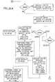
- buttons PB10 on the control console are pressed and switch SW10 is moved to the ON position.
- the program of the programmable logic controller PLC checks to make sure that button PB10 and switch SW10 were operated less than 3 seconds of each other. If the elapsed time is equal to or over 3 seconds, the change in position of SW10 is not recognized.
- the two temperature switches TS10 and TS20 also shown in FIG.
- the wellbore pressure P2 is checked to see if below 0.3MPA (50 PSI). While the embodiments of the present invention, particularly FIGS. 21A to 30 , propose specific values, parameters or ranges, it should be understood that other values, parameters and ranges could be used and should be used for the particular application. For example, the value for checking the wellbore pressure P2 was changed from "WB ⁇ 0.3 MPa" ("WB ⁇ 50 PSI") in FIG. 22 to "WB ⁇ 0.5 MPa" ("WB ⁇ 75 PSI”) for a different application.
- the level switches are positioned to indicate when the tank 634 is overfull (no room for heat expansion of the oil), when the tank is low (oil heater coil is close to being exposed), or when the tank is empty (oil heater coil is exposed). As long as the tank 634 is not overfull or empty, the power unit will pass this check by the PLC program.
- valves V80 and V90 are placed in their open positions, as shown in FIG. 21B . These valve openings unload gear pumps P2 and P3 , respectively, so that when motor M1 starts, the oil is bypassed to tank 634 . Valve V150 is also placed in its open position, as shown in FIG. 21A , so that any other fluid in the system can circulate back to tank 634 .
- pump P1 which is powered by motor M1 , will compensate to a predetermined value.
- the pressure recommended by the pump manufacturer for internal pump lubrication is approximately 2 MPa (300 PSI).
- the compensation of the pump P1 is controlled by valve V10 ( FIG. 21B ).
- fluid level readings outside of the allowed values will activate alarms ALARM50, ALARM60 or ALARM70 (see also below Table 2 for alarms) and their respective lights LT100 , LT50 and LT60 .
- Text messages corresponding to these alarms are displayed on display monitor DM .
- the power unit When the PLC program has checked all of the above parameters the power unit will be allowed to start. Referring to the control console CC in FIG. 31 , the light LT10 is then turned on to indicate the PUMP ON status of the power unit. Pressure gauge PG20 on console CC continues, to read the pump pressure provided by pressure transducer PT10, shown in FIG. 21B .
- the PLC program checks to see if conditions are acceptable to turn the power unit off. For example, the wellbore pressure P2 should be below 0.3MPA (50 PSI). Both the enable button PB10 must be pressed and the power switch SW10 must be turned to the OFF position within 3 seconds to turn the power unit off.
- valve V60 FIG. 21A
- V110 FIG. 21A
- V100 prevents reverse flow in case of a loss of pressure.
- Accumulator A (which allows room for heat expansion of the fluid in the latch assembly) is set at 6.2MPa (900 psi), slightly above the latch pressure 5.5MPa (800 psi), so that it will not charge.
- Fluid pilot valve V140 ( FIG. 21A ) opens so that fluid underneath the secondary piston SP goes back to tank 634 via line FM50L and valve V130 is forced closed by the resulting fluid pressure.
- Valve V70 is shown in FIG. 21A in its center position where all ports (APBT blocked) are blocked to block flow in any line.
- the pump P1 shown in FIG. 21B , compensates to a predetermined pressure of approximately 5.5MPa (800 psi).
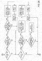
- the retainer member LP , primary piston P and secondary piston SP of the latching system are mechanically illustrated in FIG. 20 (latching system is in its closed or latched position), schematically shown in FIG. 21A , and their operations are described in the flowcharts in FIGS. 24A , 24B , 29 and 30 .
- Alternative latching systems are disclosed in FIGS. 2 , 3 , and 19 .
- the hydraulics switch SW20 on the control console CC is turned to the ON position. This allows the pump P1 to compensate to the required pressure later in the PLC program.
- the bearing latch switch SW40 on console CC is then turned to the CLOSED position.
- the program then follows the process outlined in the CLOSED leg of SW40 described in the flowcharts of FIGS. 24A and 24B .
- the pump P1 adjusts to provide 5.5MPa (800 psi) and the valve positions are then set as detailed above.
- the PLC program compares the amount of fluid that flows through flow meters FM30, FM40 and FM50 to ensure that the required amount of fluid to close or latch the latching system goes through the flow meters.
- Lights LT20, LT30, LT60 and LT70 on console CC show the proper state of the latch.
- Pressure gauge PG20 as shown on the control console CC, continues to read the pressure from pressure transducer PT10 ( FIG. 21B ).
- pressure transducer PT70 checks the wellbore pressure P2 . If the PT70 reading is above a predetermined pressure (approximately 0.3MPa (50 psi)), the power unit will not allow the retainer member LP to open or unlatch. Three-way valve V70 ( FIG. 21A ) is again in the APBT blocked position.
- Valve V60 shifts to flow position P-B and A-T .
- the fluid flows through valve V110 into the chamber to urge the primary piston P to move to allow retainer member LP to unlatch.
- the pump Pl shown in FIG. 21B , compensates to a predetermined value (approximately 13.8MPa (2000 psi)).
- Fluid pilots open valve V100 to allow fluid of the primary piston P to flow through line FM30L and the A-T ports back to tank 634 .
- the secondary piston SP is used to open or unlatch the primary piston P and, therefore, the retainer member LP of the latching system.
- pressure transducer PT70 Prior to unlatching the latching system, pressure transducer PT70 again checks the wellbore pressure P2 . If PT70 is reading above a predetermined pressure (approximately 0.3 MPa (50 psi)), the power unit will not allow the latching system to open or unlatch.
- Valve V60 is in the APBT blocked position, as shown in FIG. 21A . Valve V70 then shifts to flow position P-A and B-T .
- FIGS. 22 , 23 , 24A and 24B describe when the alarms are activated.
- Table 2 shows the lights, horn and causes associated with the activated alarms. The lights listed in Table 2 correspond to the lights shown on the control console CC of FIG. 31 .
- a text message corresponding to the cause is sent to the display monitor DM on the control console CC.
- the PLC program will run a comparison where the secondary piston SP is "bottomed out” or in its latched position, such as shown in FIG. 20 , or when only a primary piston P is used, such as shown in FIG. 19 , the piston P is bottomed out.
- the flow meter FM30 coupled to the line FM30L measures either the flow volume value or flow rate value of fluid to the piston chamber to move the piston P to the latched position, as shown in FIG. 20 , from the unlatched position, as shown in FIG. 19 .
- the flow meter FM40 coupled to the line FM40L measures the desired flow volume value or flow rate value from the piston chamber. Since the secondary piston SP is bottomed out, there should be no flow in line FM50L , as shown in FIG. 20 . Since no secondary piston is shown in FIG. 19 , there is no line FM50L or flow meter FM50 .
- the flow volume value or flow rate value measured by flow meter FM30 should be equal to the flow volume value or flow rate value, respectively, measured by flow meter FM40 within a predetermined tolerance. If a leak is detected because the comparison is outside the predetermined tolerance, the results of this FM30/FM40 comparison would be displayed on display monitor DM on control console CC, as shown in FIG. 31 , preferably in a text message, such as "ALARM90 - Fluid Leak". Furthermore, if the values from flow meter FM30 and flow meter FM40 are not within the predetermined tolerance, i.e. a leak is detected, the corresponding light LT100 would be displayed on the control console CC .
- the secondary piston SP In a less common comparison, the secondary piston SP would be in its "full up” position. That is, the secondary piston SP has urged the primary piston P , when viewing FIG. 20 , as far up as it can move to its full unlatched position.
- the flow volume value or flow rate value measured by flow meter FM30 coupled to line FM30L , to move piston P to its latched position, as shown in FIG. 20 .
- the secondary piston SP is sized so that it would block line FM40L , no fluid would be measured by flow meter FM40 . But fluid beneath the secondary piston SP would be evacuated via line FM50L from the piston chamber of the latch assembly.
- Flow meter FM50 would then measure the flow volume value or flow rate value.
- the measured flow volume value or flow rate value from flow meter FM30 is then compared to the measured flow volume value or flow rate value from flow meter FM50 .
- the compared FM30/FM50 values are within a predetermined tolerance, then no significant leaks are considered detected. If a leak is detected, the results of this FM30/FM50 comparison would be displayed on display monitor DM on control console CC , preferably in a text message, such as "ALARM 100 - Fluid Leak". Furthermore, if the values from flow meter FM30 and flow meter FM50 are not within a predetermined tolerance, the corresponding light LT100 would be displayed on the control console CC .
- the primary piston P is in its full unlatched position and the secondary piston SP is somewhere between its bottomed out position and in contact with the fully unlatched piston P .
- the flow volume value or flow rate value measured by the flow meter FM30 to move piston P to its latched position is measured. If the secondary piston SP is sized so that it does not block line FM40L , fluid between secondary piston SP and piston P is evacuated by line FM40L .
- the flow meter FM40 measures the flow volume value or flow rate value via line FM40L . This measured value from flow meter FM40 is compared to the measured value from flow meter FM30 . Also, the flow value beneath secondary piston SP is evacuated via line FM50L and measured by flow meter FM50.
- An alternative to the above leak detection methods of comparing measured values is to use a predetermined or previously calculated value.
- the PLC program then compares the measured flow value in and/or from the latching system to the predetermined flow value plus a predetermined tolerance.
- the flow meters FM30 , FM40 and FM50 are also monitored so that if fluid flow continues after the piston P has moved to the closed or latched position for a predetermined time period, a possible hose or seal leak is flagged.
- alarms ALARM90 , ALARM100 and ALARM110 could be activated as follows:
- Alarm ALARM90 - primary piston P is in the open or unlatched position.
- the flow meter FM40 measured flow value is compared to a predetermined value plus a tolerance to indicate the position of piston P .
- the flow meter FM40 reaches the tolerance range of this predetermined value, the piston P is indicated in the open or unlatched position. If the flow meter FM40 either exceeds this tolerance range of the predetermined value or continues to read a flow value after a predetermined time period, such as an hour, the PLC program indicates the Alarm ALARM90 and its corresponding light and text message as discussed herein.
- Alarm ALARM100 - secondary piston SP is in the open or unlatched position.
- the flow meter FM50 measured flow value is compared to a predetermined value plus a tolerance to indicate the position of secondary piston SP .
- the flow meter FM50 reaches the tolerance range of this predetermined value, the secondary piston SP is indicated in the open or unlatched position. If the flow meter FM50 either exceeds this tolerance range of the predetermined value or continues to read a flow value after a predetermined time period, such as an hour, the PLC program indicates the alarm ALARM100 and its corresponding light and text message as discussed herein.
- Alarm ALARM110- primary piston P is in the closed or latched position.
- the flow meter FM30 measured flow value is compared to a predetermined value plus a tolerance to indicate the position of primary piston P .
- the flow meter FM30 reaches the tolerance range of this predetermined value, the primary piston P is indicated in the closed or latched position. If the flow meter FM30 either exceeds this tolerance range of the predetermined value or continues to read a flow value after a predetermined time period, such as an hour, the PLC program indicates the alarm ALARM110 and its corresponding light and text message as discussed herein.
- Additional methods are contemplated to indicate the position of the primary piston P and/or secondary piston SP in the latching system.
- One example would be to use an electrical sensor, such as a linear displacement transducer, to measure the distance the selected piston has moved.
- This type of sensor is a non-contact sensor as it does not make physical contact with the target, and will be discussed below in detail.
- the information from the sensor may be remotely used to indirectly determine whether the retainer member is latched or unlatched based upon the position of the piston.
- FIG. 19 Another method could be drilling the housing of the latch assembly for a valve that would be opened or closed by either the primary piston P , as shown in the embodiment of FIG. 19 , or the secondary piston SP , as shown in the embodiment of FIGS. 20 , 32 and 33 .
- a port PO would be drilled or formed in the bottom of the piston chamber of the latch assembly.
- Port PO is in fluid communication with an inlet port IN ( FIG. 32 ) and an outlet port OU ( FIG. 33 ) extending perpendicular (radially outward) from the piston chamber of the latch assembly.
- These perpendicular ports would communicate with respective passages INP and OUP that extend upward in the radially outward portion of the latch assembly housing.
- Housing passage OUP is connected by a hose to a pressure transducer and/or flow meter.
- a machined valve seat VS in the port to the piston chamber receives a corresponding valve seat, such as a needle valve seat.
- the needle valve seat would be fixedly connected to a rod R receiving a coil spring CS about its lower portion to urge the needle valve seat to the open or unlatched position if neither primary piston P ( FIG. 19 embodiment) nor secondary piston SP ( FIGS. 20 , 32 and 33 embodiments) moves the needle valve seat to the closed or latched position.
- Rod R makes physical contact with secondary piston SP .
- An alignment retainer member AR is sealed as the member is threadably connected to the housing H .
- the upper portion of rod R is slidably sealed with retainer member AR .
- valve is indicated open. This open valve indicates the piston is in the open or unlatched position. If no flow value and/or pressure is detected in the respective flow meter and/or pressure transducer communicating with passage OUP , then the valve is indicated closed. This closed valve indicates the piston is in the closed or latched position. This information may then be remotely used to indirectly determine whether the retainer member is latched or unlatched depending upon the position of the piston.
- the above piston position would be shown on the console CC , as shown in FIG. 31 , by lights LT20 or LT60 and LT30 or LT70 along with a corresponding text message on display monitor DM.
- FIGS. 34-35 , 35A , and 36-39A Other embodiments of latch position indicator systems using latch position indicator sensors are shown in FIGS. 34-35 , 35A , and 36-39A .
- latch assembly 3020 is bolted with bolts 3070 to housing section 3080 .
- Other attachment means are contemplated.
- Retainer member 3040 is in the latched position with RCD 3010 .
- Retainer member 3040 is extended radially inwardly from the latch assembly 3020 , engaging latching formation 3012 on the RCD 3010.
- An annular piston 3050 is in the first position, and blocks retainer member 3040 in the radially inward position for latching with RCD 3010 .
- latching assembly 3020 is a single hydraulic latch assembly similar to latching assembly 210 in FIG. 2 .
- piston 3050 has an inclined or ramped exterior surface 3052 .
- Latch position indicator sensor housing 3092 is attached with latch assembly 3020 .
- Latch position indicator sensor 3090 is mounted with housing 3092 .
- Sensor 3090 can detect the distance from the sensor 3090 to the targeted inclined surface 3052 , including while piston 3050 moves.
- the slope of the inclined surface 3052 is shown as negative, it should be understood that the slope of the inclined surface 3052 may be positive, which is true for all the inclined surfaces on the pistons on all the other embodiments shown below.
- Enlarged views of a housing and sensor similar to housing 3092 and sensor 3090 are shown in FIGS. 40-42 .
- sensor 3090 transmits an electrical signal through line 3094 .
- the output signal from sensor 3090 may be interpreted to remotely determine the position and/or movement of piston 3050 , and therefore indirectly the position and/or movement of retainer member 3040 , as will be discussed in detail below.
- sensor 3090 is mounted laterally in relation to piston 3050 .
- sensor 3090 is a non-contact type sensor in that it does not make physical contact with piston 3050 .
- contact type sensors that do make contact with piston 3050 are contemplated. Contact and non-contact type sensors may be used interchangeably for all the embodiments of the invention.
- the information from sensor 3090 may be used remotely to indirectly determine whether retainer member 3040 is latched or unlatched from the position of piston 3050 .
- Latch position indicator sensor 3090 may preferably be an analog inductive proximity sensor used to measure travel of metal targets, such as sensor Part No. Bi 8-M18-Li/Ex i with Identification No. M1535528 available from Turck Inc. of Madison, Minnesota.
- Another similar analog inductive proximity sensor is model number BAW M18MI-ICC50B-S04G available from Balluff Inc.
- an analog inductive sensor provides an electrical output signal that varies linearly in proportion to the position of a metal target within its working range, as shown in FIGS. 43-45 .
- the inductive proximity sensor emits an alternating electro-magnetic sensing field based upon the eddy current sensing principle. When a metal target enters the sensing field, eddy currents are induced in the target, reducing the signal amplitude and triggering a change of state at the sensor output. The distance to the target may be determined from the sensor output. The motion of the target may also be determined from the sensor output.
- sensors both contact type and non-contact type, for measuring distance and/or movement are contemplated for all embodiments of the invention, including, but not limited to, magnetic, electric, capacitive, eddy current, inductive, ultrasonic, photoelectric, photoelectric-diffuse, photoelectric-retro-reflective, photoelectric-thru-beam, optical, laser, mechanical, magneto-inductive, magneto-resistive, giant magneto-resistive (GMR), magno-restrictive, Hall-Effect, acoustic, ultrasonic, auditory, radio frequency identification, radioactive, nuclear, ferromagnetic, potentiometric, wire coil, limit switches, encoders, linear position transducers, linear displacement transducers, photoelectric distance sensors, magneto-inductive linear position sensors, and inductive distance sensors.
- GMR giant magneto-resistive
- Hall-Effect Hall-Effect
- sensors may be used with the same latch assembly, such as latch assembly 3100 in FIG. 36 . It is contemplated that all sensors for all embodiments of the invention may be contact type sensors or non-contact type sensors. Although the preferred sensor shown in FIG. 34 is flush mounted, other similar sensors may be used that are not flush mounted. It is also contemplated that the transmission from any sensor shown in any embodiment may be wireless, such as shown in FIG. 38 , so that line 3094 may not be necessary. The output from the sensors provide for remote determination of the position and/or movement of the piston or retainer member that is targeted.
- a signal inducing device such as a magnet, an active radio frequency identification device, a radioactive pill, or a nuclear transmitting device
- a signal inducing device may be mounted on piston 3050 , similar to those shown in Pub. No. US 2008/0236819 , that may be detected by a receiving device or a sensor mounted on latching assembly 3020 to determine the position of piston 3050.
- a signal inducing device may be mounted on a retainer member, such as retainer member 3040 , as shown in FIGS, 34 and 35 .
- a passive radio frequency identification device is also contemplated to be mounted on piston 3050 or retainer member 3040 .
- a sensor may be mounted on piston 3050 or retainer member 3040 , which may detect a signal inducing device on latching assembly 3020 . It is also contemplated that signal inducing devices may be mounted on a combination of a retainer member, a piston and/or other latch assembly components, and a separate signal receiving device used to detect the position of the retainer member and/or piston.
- first piston 3050 is in the second position and retainer member 3040 is in the radially outward or unlatched position.
- the RCD 3010 shown in FIG. 34 has been removed.
- auxiliary piston 3060 may be used to urge first piston 3050 into the second position, it is not required, as shown in FIG. 35 .
- Auxiliary piston 3060 provides a backup if first piston 3050 will not respond to hydraulic pressure alone.
- latch assembly 4000 may be bolted to housing section 4070 .
- Other attachment means are contemplated.
- Retainer member 4004 is in the latched position with RCD 4002.
- Retainer member 4004 is extended radially inwardly from the latch assembly 4000, engaging latching formation 4006 on the RCD 4002 .
- Retainer member 4004 asserts a downward force on RCD 4002, and shoulder 4060 in latching assembly 4000 asserts an upward force on RCD 4002, thereby gripping or squeezing RCD 4002 when it is latched, to resist its outer housing and/or the bearing assembly from rotating with the rotation of the drill string.
- a shoulder similar to shoulder 4060 may be used on all embodiments of the invention.
- An annular piston 4022 is in the first position, and blocks retainer member 4004 in the radially inward position for latching with RCD 4002. Movement of the piston 4022 from a second position to the first position compresses or moves retainer member 4004 to the engaged or latched position shown in FIG. 35A .
- the piston 4022 can be implemented as a plurality of separate pistons disposed about the latch assembly.
- First piston 4022 may be moved into the second position directly by hydraulic fluid.
- a second or auxiliary piston 4072 may be used to urge the first piston 4022 into the second position to unlatch the RCD 4002 .
- latching assembly 4000 is a single hydraulic latch assembly similar to latching assembly 210 in FIG. 2 .
- retainer member 4004 has an inclined surface 4010 .
- Latch position indicator sensor 4012 is mounted in latch assembly 4000 so as to detect the distance from the sensor 4012 to the targeted inclined surface 4010 , including while retainer member 4004 moves.
- Sensor 4012 transmits an electrical signal through lines ( 4014 , 4018 ).
- Fitting 4016 is sealingly mounted on latching assembly 4000 . The output signal from sensor 4012 may be interpreted remotely to directly determine the position and/or movement of retainer member 4004 .
- sensor 4012 is mounted laterally in relation to retainer member 4004 .
- sensor 4012 is a non-contact type sensor in that it does not make physical contact with retainer member 4004 .
- contact type sensors that do make contact with retainer member 4004 are contemplated. Contact and non-contact type sensors may be used interchangeably for all the embodiments of the invention.
- the information from sensor 4012 may be used remotely to directly determine whether retainer member 4004 is latched or unlatched.
- Retainer member 4004 may need to move inwardly a greater distance for other latched equipment than it does for RCD 4002 .
- Blocking shoulders slot 4008 allows retainer member 4004 to move a limited travel distance (even a distance considered to be an override position) or until engaged with different outer diameter inserted oilfield devices. It is contemplated that a blocking shoulder slot, such as blocking shoulder slot 4008 , may be used with all embodiments of the invention. As will be discussed below, it is contemplated that the anticipated movement of retainer member 4004 for different latched oilfield devices may be programmed into the PLC.
- First piston 4022 has an inclined or ramped exterior surface 4024 .
- Latch position indicator sensor housing 4028 is attached with latch assembly 4000 .
- Latch position indicator sensor 4026 is mounted with housing 4028 .
- Sensor 4026 can detect the distance from the sensor 4026 to the targeted inclined surface 4024 , including while piston 4022 moves. Enlarged views of a housing and sensor similar to housing 4028 and sensor 4026 are shown in FIGS. 40-42 .
- sensor 4026 transmits an electrical signal through line 4030 .
- the output signal from sensor 4026 may be interpreted to remotely determine the position and/or movement of piston 4022 , and therefore indirectly the position and/or movement of retainer member 4004 .
- sensor 4026 is mounted laterally in relation to piston 4022 .
- sensor 4026 is a non-contact type sensor in that it does not make physical contact with piston 4022 .
- contact type sensors that do make contact with piston 4022 are contemplated.
- the information from sensor 4026 may be used remotely to indirectly determine whether retainer member 4004 is latched or unlatched from the position of piston 4022 .
- Second piston 4072 has an inclined or ramped exterior surface 4038.
- Latch position indicator sensor housing 4044 is attached with latch assembly 4000.
- Latch position indicator sensor 4036 is mounted with housing 4044.
- Sensor 4036 can detect the distance from the sensor 4036 to the targeted inclined surface 4038, including while second piston 4072 moves.
- Sensor 4036 transmits an electrical signal through line 4046. The output signal from sensor 4036 may be interpreted to remotely determine the position and/or movement of second piston 4072 , and therefore indirectly the position and/or movement of retainer member 4004 .
- Sensor 4036 is mounted laterally in relation to second piston 4072 .
- Sensor 4036 is a non-contact type sensor in that it does not make physical contact with piston 4072 .
- contact type sensors that do make contact with piston 4072 are contemplated.
- Contact and non-contact type sensors may be used interchangeably for all the embodiments of the invention.
- the information from sensor 4036 may be used remotely to indirectly determine whether retainer member 4004 is latched or unlatched from the position of piston 4072 . It is contemplated that sensors similar to sensors ( 4036 , 4048 ) may be positioned with a second piston similar to second piston 4072 in any embodiment of the invention.
- Sensor 4048 is positioned axially in relation to second piston 4072 . It is contemplated that sensor 4048 may be sealed from hydraulic pressure. Sensor 4048 can detect the distance from the sensor 4048 to the targeted second piston bottom surface 4080 , including while second piston 4072 moves. Sensor 4048 transmits an electrical signal through lines ( 4052 , 4058 ) connected with inner conductive rings 4050 mounted on the inner body 4084 of latch assembly 4000 . Inner conductive rings 4050 are positioned with outer conductive rings 4082 on the outer body 4086 of latch assembly 4000 . It is contemplated that conductive rings ( 4050 , 4082 ) may be made of a metal that conducts electricity with minimal resistance, such as copper.
- the output signal from sensor 4048 travels through lines ( 4053 , 4058 ) and may be interpreted to remotely determine the position and/or movement of second piston 4072 , and therefore indirectly the position and/or movement of retainer member 4004 , as will be discussed in detail below.
- Second fitting 4056 is sealingly mounted with latch assembly 4000 .
- sensor 4048 is a non-contact type sensor in that it does not make physical contact with second piston 4072 .
- contact type sensors that do make contact with second piston 4072 are contemplated.
- the information from sensor 4048 may be used remotely to indirectly determine whether retainer member 4004 is latched or unlatched from the position of second piston 4072.
- Reservoir 4020 may contain pressurized fluid, such as a hydraulic fluid, such as water, with or without cleaning additives. However, other fluids (liquid or gas) are contemplated.
- the fluid may travel through lines ( 4032 , 4034 , 4040) to clean off debris around and on the sensors ( 4026 , 4036 ) or targeted inclined surfaces ( 4024 , 4038 ).
- One-way gate valve 4042 allows the fluid to travel out of latch assembly 4000 . While not illustrated, it is contemplated that directed nozzles, such as a jet nozzle, could be positioned in lines 4032 , 4034 to enhance the pressured cleaning of the sensors. Also, it is contemplated that pumps could be provided to provide pressurized fluid.
- one pump could be provided in line 4032 and a second pump could be provided in line 4034.
- a gravity flow having a desirable head pressure could be used.
- the same hydraulic fluid used to move pistons ( 4022 , 4072 ) may be used to clean debris around and on the sensors ( 4026 , 4036 ) or targeted inclined surfaces ( 4024 , 4038 ).
- the fluid cleaning system shown in FIG. 35A and described above may be used with any embodiment of the invention, including to clean contact sensors, such as sensor 4180 and targeted surface 4182 shown in FIG. 39A .
- FIG. 36 it shows a dual hydraulic latch assembly 3100 similar to latch assembly 300 shown in FIG. 3 .
- the first or upper latch subassembly comprises first piston 3130 , second piston 3140 , and first retainer member 3120 .
- the second or lower latch subassembly comprises third piston 3150 and second retainer member 3160 . It should be understood that the positions of the first and second subassemblies may be reversed.
- Latch assembly 3100 is latchable to a housing section 3110 , shown as a riser nipple, allowing remote positioning and removal of the latch assembly 3100 .
- Retainer member 3160 is in the radially inward or unlatched position with housing section 3110 .
- Latch position indicator sensor housing 3194 is positioned with latch assembly 3100 adjacent to the first latch subassembly of latch assembly 3100.
- Latch position indicator sensor 3192 is mounted with housing 3194 .
- Sensor 3192 can detect the distance from the sensor 3192 to the targeted top surface 3190 of piston 3130 , including while piston 3130 moves.
- Sensor 3192 and housing 3194 may be pressure sealed from the hydraulic fluid above piston 3130 .
- Enlarged views of a housing and sensor similar to housing 3194 and sensor 3192 are shown in FIGS. 40-42 .
- sensor 3192 transmits electrical signals through line 3196 .
- sensor 3192 may be interpreted remotely to determine the position of piston 3130 , and therefore indirectly the position of retainer member 3120 , as will be discussed in detail below.
- sensor 3192 is mounted axially in relation to piston 3130 .
- Sensor 3192 is a non-contact sensor as it does not make physical contact with piston 3130 .
- a contact sensor is also contemplated for all embodiments of the invention.
- Latch position indicator sensor housing 3170 is attached with housing section 3110 adjacent to the second latch subassembly of latch assembly 3100.
- Latch position indicator sensor 3172 is mounted with housing 3170 .
- Sensor 3172 can detect the distance from the sensor 3172 to the targeted exterior surface 3180 of retainer member 3160 , including while retainer member 3160 moves.
- Sensor 3172 transmits electrical signals through line 3174 .
- the output signal from sensor 3172 may be interpreted remotely to directly determine the position of retainer member 3160 , as will be discussed in detail below.
- Sensor 3172 is mounted axially in relation to retainer member 3160 .
- Sensor 3172 is a non-contact type sensor.
- fluid used in different hydraulic configurations may be used to clean debris off sensor 3172 and the targeted exterior surface 3180 of retainer member 3160 . It is contemplated that the same hydraulic fluid used to move the pistons ( 3130 , 3160 ) in latch assembly 3100 may be used. Alternatively, it is also contemplated that the fluid may be stored in a separate reservoir. The fluid may move through one or more passageways in housing section 3110 or latch assembly 3100. It is contemplated that the same cleaning system and method may be used with all embodiments of the invention. Also, it contemplated that the cleaning system may be used with all of the sensors on an embodiment, such as sensor 3192 in FIG. 36 .
- a second latch subassembly 3270 is shown for a dual hydraulic latch assembly similar to the second latch subassemblies of latch assemblies ( 300 , 3100 ) shown in FIGS. 3 and 36 , respectively.
- the second latch subassembly 3270 comprises piston 3210 and retainer member 3220 .
- Latch subassembly 3270 is latchable to a housing section 3200 , allowing remote positioning and removal of the latch subassembly 3270 .
- Retainer member 3220 is in the radially inward or unlatched position with housing section 3200 . When retainer member 3220 moves outwardly into the latched position it contacts latching formation 3232 in housing section 3200 .
- Latch position indicator sensor housing 3250 is attached with housing section 3200 adjacent to the second latch subassembly 3270 .
- Latch position indicator sensor 3240 is positioned with housing 3250 .
- Sensor 3240 can detect the distance from the sensor 3240 to the exterior surface 3230 of retainer member 3220 , including while retainer member 3220 moves.
- Sensor 3240 is a non-contact type sensor.
- Sensor 3240 transmits electrical signals through line 3260. The output signal from sensor 3240 may be interpreted remotely to directly determine the movement and/or position of retainer member 3220 , as will be discussed in detail below.
- FIG. 38 shows a dual hydraulic latch assembly 3300 similar to latch assembly 300 shown in FIG. 3 and latch assembly 3100 shown in FIG. 36 .
- the first or upper latch subassembly comprises first piston 3340 , second piston 3330 , and first retainer member 3350 .
- the second or lower latch subassembly comprises third piston 3360 and second retainer member 3370.
- Latch assembly 3300 is latchable to a housing section 3320 , shown as a riser nipple, allowing remote positioning and removal of the latch assembly 3300 .
- Retainer member 3370 is in the radially inward or unlatched position with housing section 3320 .
- alignment groove 3332 on the latch assembly 3300 aligns with alignment member 3334 on the surface of housing section 3320 to insure that openings (3322 , 3326) in housing section 3320 align with corresponding openings ( 3324 , 3328 ) in latch assembly 3300 .
- the use and shape of member 3334 and groove 3332 are exemplary and illustrative only and other formations and shapes and other alignment means may be used.
- Auxiliary piston 3330 in the first subassembly has urged first piston 3340 into the second position.
- Retainer member 3350 has moved radially outwardly to the unlatched position. When retainer member 3350 moves inwardly into the latched position it contacts latching formation 3312 on oilfield device 3310 .
- two latch position indicator sensor housings are positioned adjacent to the first latch subassembly of latch assembly 3300 .
- Latch position indicator sensor housing 3394 is also attached with latch assembly 3300 .
- Latch position indicator sensor 3396 is positioned with housing 3394 and can detect the distance from the sensor 3396 to the top surface 3398 of piston 3340 , including while piston 3340 moves.
- Sensor 3396 and housing 3394 may be pressure sealed from the hydraulic fluid above piston 3340 .
- Sensor 3396 is shown as wireless, although, as disclosed above, the sensor may send electrical signals through a line.
- Sensor 3396 is mounted axially in relation to piston 3340.
- Sensor 3396 is a non-contact type sensor, whose output may be interpreted remotely to indirectly determine the position and/or movement of retainer member 3350 , as will be discussed below.
- latch position indicator sensor housing 3390 is positioned with housing section 3320.
- Latch position indicator sensor 3392 is positioned with housing 3390 to detect the distance from the sensor 3392 to the inclined surface 3342 of piston 3340 through aligned openings ( 3322 , 3324 ), including while piston 3340 moves.
- Sensor 3392 is shown as wireless, although it may send electrical signals through a line.
- Sensor 3392 is mounted laterally in relation to piston 3340.
- two housings ( 3390 , 3394 ) with respective sensors ( 3392 , 3396 ) are shown in FIG. 38 , it is contemplated that either housing with its respective sensor may be removed so that there may be only one housing and sensor positioned with the first latch subassembly.
- the two sensors ( 3392 , 3396 ) provide redundancy, if desired.
- the same redundancy may be used on any embodiment of the invention, including on the second or lower latch subassemblies.
- sensor 3392 may not be the same type of sensor as sensor 3396, although it is contemplated that they may be the same type sensor.
- Sensor 3392 is a non-contact type sensor whose output may be used to indirectly and remotely determine the position and/or movement of retainer member 3350, from the position and/or movement of piston 3340, as will be discussed below.
- latch position indicator sensor housing 3380 is attached with housing section 3320 adjacent to the second or lower latch subassembly of latch assembly 3320.
- Latch position indicator sensor 3382 is mounted with housing 3380. Sensor 3382 can detect the distance from the sensor 3382 to the inclined surface 3362 of piston 3360 through aligned openings (3326, 3328), including while piston 3360 moves. Sensor 3382 is shown as wireless, although it may alternatively transmit electrical signals through a line. Sensor 3382 is a non-contact sensor. The output signal from sensor 3382 may be interpreted to remotely determine the position and/or movement of third piston 3360, and therefore indirectly the position and/or movement of retainer member 3370, as will be discussed in detail below. Sensor 3382 is mounted laterally in relation to piston 3360.
- a dual hydraulic latch assembly 3400 is shown similar to latch assembly 300 shown in FIG. 3 , latch assembly 3100 shown in FIG. 36 , and latch assembly 3300 shown in FIG. 38 .
- the first or upper latch subassembly comprises first piston 3440, second piston 3456, and first retainer member 3430.
- the second or lower latch subassembly comprises third piston 3460 and second retainer member 3462.
- Latch assembly 3400 is latchable to a housing section 3420, shown as a riser nipple, allowing remote positioning and removal of the latch assembly 3400.
- Retainer member 3462 is in the radially outward or latched position with housing section 3420.
- Retainer member 3430 is in the radially inward or latched position and is in contact with latching formation 3411 on oilfield device 3410.
- latch position indicator sensor housing 3450 is attached with latch assembly 3400 adjacent to the first latch subassembly of latch assembly 3400.
- Latch position indicator sensor 3452 is mounted with sensor housing 3450. Sensor 3452 can detect the distance from the sensor 3452 to the inclined surface 3442 of piston 3440, including while piston 3440 moves. Sensor 3452 may be wireless or, as shown in FIG. 39 , it may send electrical signals through line 3454. Sensor 3452 is positioned laterally in relation to piston 3440. Sensor 3452 is a non-contact sensor, but as with all embodiments, it is contemplated that contact and non-contact sensors may be used interchangeably. As will be discussed below, the output from sensor 3452 may be interpreted to remotely determine the position and/or movement of piston 3440, and therefore indirectly position and/or movement of retainer member 3430.
- Latch position indicator sensor housing 3470 is positioned with housing section 3320 adjacent to the second or lower latch subassembly of latch assembly 3400.
- Latch position indicator sensor 3472 is mounted with sensor housing 3470 and it can detect the distance from the sensor 3472 to the exterior surface 3464 of retainer member 3462, including while member 3462 moves.
- Sensor 3472 may be wireless or, as shown in FIG. 39 , it may send electrical signals through line 3474. The information from sensor 3472 may be used to remotely and directly determine the movement and/or position of retainer member 3462, as will be discussed in detail below.
- Sensor 3472 is positioned axially in relation to retainer member 3462.
- Sensor 3472 is a non-contact sensor, but as with all embodiments, it is contemplated that contact and non-contact sensors may be used interchangeably.
- FIG. 39A a dual hydraulic latch assembly 4100 is shown similar to latch assembly 300 shown in FIG. 3 , latch assembly 3100 shown in FIG. 36 , latch assembly 3300 shown in FIG. 38 , and latch assembly 3400 shown in FIG. 39 .
- the first or upper latch subassembly comprises first piston 4118, second piston 4120, and first retainer member 4106.
- the second or lower latch subassembly comprises third piston 4160 and second retainer member 4166.
- Latch assembly 4100 is latchable to a housing section 4164, shown as a riser nipple, allowing remote positioning and removal of the latch assembly 4100.
- Second retainer member 4166 is in the radially outward or latched position with housing section 4164.
- First retainer member 4106 is in the radially inward or latched position and is in contact with latching formation 4104 on oilfield device 4102.
- Blocking shoulders slot 4116 allows for first retainer member 4106 to move a limited travel distance or until engaged with an inserted oilfield device.
- shoulder 4190 allows for oilfield device 4102 to be gripped or squeezed between inner body shoulder 4190 and retainer member 4106 , thereby resisting rotation.
- Latch position indicator sensor 4110 is sealingly positioned in latch assembly 4100 adjacent to the first retainer member 4106 .
- Sensor 4110 can detect the distance from the sensor 4110 to the inclined surface 4108 of retainer member 4106, including while retainer member 4106 moves.
- Sensor 4110 may be wireless or, as shown in FIG. 39A , it may send electrical signals through lines, generally indicated as 4114 , and line 4112 .
- Sensor 4110 is positioned laterally in relation to retainer member 4106 .
- Sensor 4110 is a contact type sensor in that it makes physical contact with the target inclined surface 4108 . As will be discussed below, the output from sensor 4110 may be interpreted to remotely directly determine the position and/or movement of retainer member 4106 .
- Latch position indicator sensor 4128 is attached with latch assembly 4100 adjacent to the first latch subassembly of latch assembly 4100. Sensor 4128 can detect the distance from the sensor 4128 to the inclined surface 4132 of piston 4118 , including while piston 4118 moves. Sensor 4118 may be wireless or, as shown in FIG. 39 , it may send electrical signals through line 4130 . Sensor 4128 is sealingly positioned laterally in relation to piston 4118 . Sensor 4128 is a contact type sensor in that it makes physical contact with the target inclined surface 4132 . The output from sensor 4128 may be interpreted to remotely determine the position and/or movement of piston 4118 , and therefore indirectly position and/or movement of retainer member 4106 . It should be understood that the plurality of sensors shown in FIG. 39A are for redundancy, and it is contemplated that fewer or more sensors may be used.
- Latch position indicator sensor 4122 is sealingly positioned axially in relation to first piston 4118 .
- Sensor 4122 is a contact type sensor in that it makes physical contact with the target first piston top surface 4192 when first piston 4118 is in the unlatched position. Sensor 4122 does not make contact with piston 4118 when piston 4118 is in the latched position, as shown in FIG. 39A .
- Sensor 4122 may send electrical signals through lines, generally indicated as 4124 , and line 4126 . The output from sensor 4122 may be interpreted to remotely determine the position of piston 4118, and therefore indirectly position and/or movement of retainer member 4106.
- Second piston 4120 has an inclined or ramped exterior surface 4136.
- Latch position indicator sensor 4134 is positioned so as to detect the distance from the sensor 4134 to the targeted inclined surface 4136, including while second piston 4120 moves. Sensor 4134 transmits an electrical signal through line 4138. The output signal from sensor 4134 may be interpreted to remotely determine the position and/or movement of second piston 4120, and therefore indirectly the position and/or movement of retainer member 4106.
- Sensor 4134 is sealingly mounted laterally in relation to second piston 4120.
- Sensor 4134 is a contact type sensor in that it makes physical contact with inclined surface 4136. Contact and non-contact type sensors may be used interchangeably for all the embodiments of the invention. As can further be understood, the information from sensor 4134 may be used remotely to indirectly determine whether retainer member 4106 is latched or unlatched from the position of second piston 4120.
- Sensor 4140 is sealingly positioned axially in relation to second piston 4120. That is, it is contemplated that sensor 4140 may be sealed from, among other elements, hydraulic pressure and debris. Sensor 4140 can detect the distance from the sensor 4140 to the targeted second piston bottom surface 4142, including, for a limited distance, while second piston 4120 moves. Sensor 4140 transmits an electrical signal through lines, generally indicated as 4144, connected with inner conductive rings, similar to ring 4146, mounted on the inner body 4194 of latch assembly 4100. Inner conductive rings are positioned with outer conductive rings, similar to ring 4148, on the outer body 4196 of latch assembly 4100. It is contemplated that conductive rings (4146, 4148) may be made of a metal that conducts electricity with minimal resistance, such as copper.
- sensor 4140 travels through lines, generally indicated as 4144, and line 4145 and may be interpreted to remotely determine the position and/or movement of second piston 4120, and therefore indirectly the position and/or movement of retainer member 4106.
- sensor 4140 is a contact type sensor in that it makes physical contact with second piston 4120 for a limited travel distance or for its full travel distance.
- Latch position indicator sensor 4180 is sealingly positioned adjacent to the second or lower latch subassembly of latch assembly 4100.
- Latch position indicator sensor 4180 is positioned with housing section 4164 so that it can detect the distance from the sensor 4180 to the exterior surface 4182 of retainer member 4166, including while member 4166 moves for a limited travel distance or for its full travel distance.
- Sensor 4180 may be wireless or, as shown in FIG. 39A , it may send electrical signals through line 4184. The information from sensor 4180 may be used to remotely and directly determine the movement and/or position of retainer member 4166, as will be discussed in detail below.
- Sensor 4180 is positioned axially in relation to retainer member 4166.
- Sensor 4180 is a contact type sensor, but as with all embodiments, it is contemplated that contact and non-contact sensors may be used interchangeably.
- sensor 4170 is positioned laterally in relation to retainer member 4166. It is contemplated that retainer member 4166 may be made substantially from one metal, such as steel, and that insert 4168 may be made substantially from another metal, such as copper or aluminum. Other metals and combination of metals and arrangements are contemplated. Distinguished from the other sensors in FIG. 39A , sensor 4170 is a non-contact sensor that can determine the position and/or movement of retainer member 4166 from the movement of the ring 4168. When the distance from the latch position indicator sensor 4170 to the metal target is kept constant, the output from sensor 4170 will change when the target metal changes due to the difference in magnetic properties of the target. Therefore, the movement and/or position of retainer member 4166 may be obtained from sensor 4170.
- sensor 4170 may be an analog inductive sensor, although other types are contemplated.
- Sensor 4170 sends electrical signals through lines, generally indicated as 4172, and conductive rings, such as rings ( 4174 , 4176 ) as has been described above.
- sensors ( 4180 , 4170 ) may directly determine whether retainer member 4166 is latched or unlatched.
- sensor 4150 is sealingly positioned axially in relation to third piston 4160.
- Sensor 4150 is a contact sensor that makes contact with top surface 4162 of third piston 4160 when third piston 4160 is in the unlatched position.
- Sensor 4150 sends electrical signals through lines, generally indicated as 4152, and conductive rings, such as rings ( 4154 , 4156 ) as has been described above.
- the information from sensor 4150 can be used remotely to indirectly determine whether retainer member 4166 is latched or unlatched.
- RCD 4240 is shown latched to diverter housing 4200 with lower latch retainer member 4310.
- lower hydraulic annular piston 4300 moves lower retainer member 4310 to its inward latched position
- lower piston 4300 is latched.
- Active seal 4220 is engaged with drill string 4230.
- Packer 4210 supports seal 4220, and upper retainer member 4260 is latched with packer 4210.
- upper hydraulic annular piston 4250 moves upper retainer member 4260 to it inward latched position
- upper piston 4250 is latched.
- Bearings 4273 are positioned between annular outer bearing housing 4360 and annular inner bearing housing 4370.
- upper and lower retainer members ( 4260 , 4310 ) are unlatched, and active seal 4220 is deflated or unengaged with drill string 4230.
- Upper and lower pistons ( 4250 , 4300 ) are in their unlatched positions.
- RCD 4240 in operational mode, and active seal 4220 and inner bearing housing 4370 may rotate with drill string 4230.
- packer 4210 may be removed for repair or replacement of seal 4220 while the bearing assembly with inner and outer bearing housings ( 4370 , 4360 ) with bearings 4273 are left in place. Further, the RCD 4240 may be completely removed from diverter housing 4200 when lower retainer member 4310 is unlatched. As can now be understood, the positions of upper and lower pistons ( 4250 , 4300 ) may be used to determine the positions of their respective retainer members ( 4260 , 4310 ).
- Upper piston indicator pin 4270 is attached with the top surface of upper piston 4250 and travels in channel 4271. It is contemplated that pin 4270 may either be releasably attached with piston 4250 or fabricated integral with it. When upper piston 4250 is in the latched position as shown on the left side of the break line BL, upper retainer member 4260 is in its inward latched position. Sensor 4280 is positioned axially in relation to upper pin 4270. Sensor 4280 is a non-contact type sensor, such as described above and below, that does not make physical contact with the top of pin 4270 when piston 4250 is in its latched position.
- Sensor 4280 also does not make contact with pin 4270 when upper piston 4250 is in its unlatched position, as the piston 4250 is shown on the right side of the break line BL.
- Sensor 4280 may be positioned in a transparent sealed housing 4281, so that the position of pin 4270 may also be monitored visually. However, it is also contemplated that there could be no housing 4281.
- the information from sensor 4280 may be remotely used to indirectly determine the position of retainer member 4260.
- sensor 4290 is positioned laterally in relation to upper pin 4270.
- Pin 4270 has an inclined reduced diameter opposed conical surface 4272.
- Sensor 4290 may measure the distance from sensor 4290 to the target inclined surface 4272.
- Sensor 4290 is a non-contact line-of-sight sensor that is preferably an analog inductive sensor. The information from sensor 4290 may be remotely used to indirectly determine the position of retainer member 4260.
- Lower piston indicator pin 4320 engages the bottom surface of lower piston 4300 and travels in channel 4321. It is contemplated that pin 4320 may be releasably attached or integral with piston 4300. When lower piston 4300 is in the latched position as shown on the left side of the vertical break line BL, lower retainer member 4310 is in its inward latched position. Sensor 4330 is positioned axially in relation to lower pin 4320. Sensor 4330 is a non-contact type sensor that does not make contact with pin 4320. Sensor 4330 may be positioned in a transparent housing so that the position of pin 4320 may also be monitored visually. The information from sensor 4330 may be remotely used to indirectly determine the position of lower retainer member 4310.
- sensor 4350 is positioned laterally in relation to lower pin 4320.
- Pin 4320 has an inclined reduced diameter opposed conical surface 4340.
- Sensor 4350 may measure the distance from sensor 4350 to the target inclined surface 4340.
- Sensor 4350 is a non-contact sensor that is preferably an analog inductive sensor. The information from sensor 4350 may be remotely used to indirectly determine the position of lower retainer member 4310.
- FIGS. 39B1a shows the lower end of upper indicator pin 4270 of FIG. 39 threadedly and releasably attached with threads 4361 with upper piston 4250.
- Upper piston 4250 is in the unlatched position allowing the upper retainer member 4260 to move to the radially outward or unlatched position.
- Upper pin 4270 is retracted into RCD 4240 in this unlatched position. Even with upper pin 4270 in its retracted position, the upper end 4291 of pin 4270 is still shown visible but could be flush with the upper surface of channel 4271. It is contemplated that all or part of pin 4270 may be a color that is easily visible, such as red. As can now be understood, even without fluid measurement, the embodiment of FIGS.
- FIG. 39B1a and 39B1b allows for triple redundancy. It is contemplated that fewer or more sensors may also be used, and that different types of sensors may be used.
- FIG. 39B1b is similar to FIG. 39B1a except upper piston 4250 is in the latched position, and upper retainer member 4260 is in the radially inward or latched position, resulting in the upper pin 4270 protruding further from the RCD 4240.
- lower piston 4300 is in the unlatched position, allowing the lower retainer member 4310 to move to the radially outward or unlatched position.
- the upper end of lower indicator pin 4400 is threadedly and releasably attached with threads 4301 to lower piston 4300.
- Other attachment means are contemplated.
- the sensor is a contact potentiometer type circuit, generally indicated as 4410A, shown in a transparent housing or cover 4410. It is contemplated that electric current may be run through circuit sensor 4410A that includes wire coiled end 4420 of lower pin 4400.
- 39B2b shows lower piston 4300 is in the latched position resulting in lower retainer member 4310 moving to the radially inward or latched position so that lower pin 4400 further protrudes or extends from RCD 4240.
- This information could be transmitted wireless or be hardwired to a remote location.
- the electrical current information from circuit sensor 4410A may be remotely used to indirectly determine the position of lower retainer member 4310 from the position of lower piston 4300.
- transparent housing 4504 encloses the upper end 4291 of upper indicator pin 4270 allowing for visual monitoring by sensors or human eye.
- Multiple non-contact type sensors 4500 , 4502 ) are mounted on the RCD 4240. It is contemplated that sensors (4500, 4502) may be optical type sensors, such as electric eye or laser. Other types of sensors are contemplated. It is further contemplated that the transparent housing or other cover could be sized to sealably enclose the desired multiple sensors, such as sensors 4500, 4502.
- lower sensor 4502 and upper sensor 4500 will generate different output signals than when pin 4270 protrudes as shown in FIG. 39B3b .
- Sensors (4500, 4502) may also be used to determine when piston 4250 is in an intermediate position between the first position and the second position. It is contemplated for all embodiments of the invention that any of the sensors shown in any of the Figures and embodiments may also detect movement as well as position. Having the two sensors (4500, 4502) also allows for redundancy if one of the two sensors (4500, 4502) fails. Sensor 4290 targets inclined reduced diameter opposed conical surface 4247 on pin 4270. As can now be understood, even without fluid measurement, FIGS. 39B3b provide for quadruple redundancy when human visual monitoring is included. Greater or lesser redundancy is contemplated. As can now be understood, sensors ( 4290 , 4500 , 4502 ) allow for remote indirect determination of the position of upper retainer member 4260 from the position of upper piston 4250.
- upper indicator pin 4520 is retracted into the RCD 4240 as upper piston 4250 is in the unlatched position allowing the upper retainer member 4260 to move to the unlatched position. While end 4524 of upper pin 4520 is shown visible extending from its channel, it could be flush with or retracted within its channel top.
- Contact type sensor 4522 is mounted with bracket 4526 on RCD 4240. It is contemplated that a transparent housing may also be used to enclose sensor 4522 and pin end 4524. As shown in FIG. 39B4b , sensor 4522 makes contact with end 4524 of upper pin 4520 when upper piston 4250 is in the latched position.
- sensor 4522 When upper piston 4250 is in the unlatched position, sensor 4522 does not make contact with pin 4520.
- Sensor 4522 may be an electrical, magnetic, or mechanical type sensor using a coil spring, although other types of sensors are contemplated. It is contemplated that a sensor that makes continuous contact with upper pin 4520 through the full travel of pin 4520 may also be used. The information from sensor 4522 may be used to remotely indirectly determine the position of upper retainer member 4260 from the position of upper piston 4250 .
- FIGS. 40-42 show different views of an exemplary latch position indicator sensor housing 3500 that is similar to the latch position indicator sensor housings ( 3092 , 3170 , 3194 , 3250 , 3380 , 3390 , 3394 , 3450 , 3470 , 4028 , 4044 ) shown in FIGS. 34-35 , 35A , 36-39 .
- exemplary latch position indicator sensor housing 3500 may be mounted to a housing member 3520 , which may be a latch assembly, such as latch assemblies ( 3020 , 3100 , 3270 , 3300 , 3400 , 4000 , 4100 ) shown in FIGS.
- latch position indicator sensor housing 3500 is shown in FIGS. 40, 41 and 42 mounted with bolts 3510 , other means of attachment are contemplated.
- FIG. 41 shows an alternative embodiment piston 3602 without an inclining surface that may be used with any embodiment of the invention.
- piston 3602 may be primarily one metal, such as steel, and that ring insert 3600 may be a different metal, such as copper or aluminum. Other metals for piston 3602 and ring insert 3600 are contemplated.
- the output from sensor 3530 will change when the target metal changes due to the difference in magnetic properties of the target. Therefore, the movement and/or position of piston 3602 may be obtained from sensor 3530 .
- Latch position indicator sensor 3530 shown mounted with housing 3500 is similar to the sensors ( 3090 , 3172 , 3192 , 3240 , 3382 , 3392 , 3396 , 3452 , 3472 , 4012 , 4026 , 4036 , 4048 , 4060 , 4170 ) shown in FIGS. 34-35 , 35A , 36-39 and 39A .
- Sensor 3530 of FIG. 41 is preferably an analog inductive sensor. It is understood that such a sensor may detect differences in permeability of the target material. For example, aluminum is nonmagnetic and has a relatively low permeability, whereas mild steels are magnetic and typically have a relatively high permeability. Other types of sensors are also contemplated, which have been previously identified.
- FIGS. 43-45 show the representative substantially linear correlation between the magnitude of the signal output from the latch position indicator sensor, preferably an analog inductive sensor, and the distance to the targeted surface, such as inclined surfaces ( 3052 , 3342 , 3362 , 3442 ) on the respective pistons ( 3050 , 3340 , 3360 , 3440 ) in FIGS. 34 , 35 , 38 , and 39 .
- the target piston translates vertically, the distance to the target changes, thereby changing the sensor output signal.
- the analog sensor ( 3090 , 3382 , 3392 , 3452 ) may be interrogated by a programmable logic controller (PLC), microprocessor, or CPU to determine the location of the respective piston ( 3050 , 3360 , 3340 , 3440 ) within its travel range.
- Threshold values may be set, as shown in FIG. 44 as "First Condition” and "Second Condition,” that may be required to be met to establish that the target, such as piston ( 3050 , 3360 , 3340 , 3440 ), have moved to a first (latched) or second (unlatched) position.
- FIG. 44 shows that if an output signal of 17 milli-Amperes (the "Second Condition") or higher is detected, then the distance from sensor 3090 to the target 3052 is .170 or higher, which correlates to the retainer member 3040 being closed (latched), as shown in FIG. 34 . Therefore, the "Second Condition” is "Latch Closed.” If an output signal of 7 milli-Amperes (the “First Condition”) or lower is detected, then the distance from sensor 3090 to the target 3052 is .067 or lower, which correlates to the retainer member 3040 being open (unlatched), as shown in FIG. 35 .
- the "First Condition” is "Latch Open.”
- the information obtained from the movement of the piston 3050 may be used to indirectly determine the position of the retainer member 3040.
- the threshold values shown in FIG. 44 are exemplary, and other values are contemplated.
- a bandwidth of values may be used to determine the "First Condition” or the "Second Condition.”
- a bandwidth for the "Second Condition” may be a sensor output of 13 milli-Amps to 17 milli-Amps, so that if the sensor output is in that range, then the Second Condition is considered to be met.
- Such ranges may take into account tolerances.
- the range may also vary depending upon the oilfield device that is inserted into the latch assembly. For example, the retainer member may be expected to move a larger distance to latch a protective sleeve than to latch a bearing assembly. It is contemplated that it may be remotely input into the PLC that a particular oilfield device, such as an RCD, is being inserted, and that the corresponding bandwidth will then be applied.
- FIG. 44 may be used with any embodiment of the invention, although the values contained therein are exemplary only.
- FIG. 44 shows that if an output signal of 17 milli-Amperes (the "Second Condition") or higher is detected, then the distance from sensor 3240 to the target 3230 is .170 or higher, which correlates to the retainer member 3230 being open (unlatched), as it is shown in FIG. 37 . Therefore, the "First Condition" is "Latch Open.” If an output signal of 7 milli-Amperes (the "First Condition”) or lower is detected, then the distance from sensor 3240 to the target 3230 is .067 or lower, which correlates to the retainer member 3230 being closed (latched).
- the "Second Condition” is "Latch Closed.”
- the information obtained from the sensor 3240 may be used to directly determine the position of the retainer member 3220.
- the threshold values shown in FIG. 44 are exemplary, and other values are contemplated. Similar correlations may be used for the movement of the back-up piston, such as pistons ( 4072 , 4120 ) in respective FIGS. 35A and 39A .
- the PLC may also monitor the change of rate and/or output of the sensor ( 3090 , 3382 , 3392 , 3452 ) signal output.
- the change of rate and/or output will establish whether the piston ( 3050 , 3360 , 3340 , 3440 ) is moving. For example, if the piston ( 3050 , 3360 , 3340 , 3440 ) is not moving, then the change of rate and/or output should be zero. It is contemplated that monitoring the change of rate and/or output of the sensor may be useful for diagnostics.
- any combination or permutations of the following three conditions may be required to be satisfied to establish if the latch has opened or closed: (1) the threshold value (or the bandwidth) must be met, (2) the piston must not be moving, and/or (3) the hydraulic system must have regained pressure. Also, as can now be understood, several different conditions may be monitored, yet there may be some inconsistency between them. For example, if the threshold value has been met and the piston is not moving, yet the hydraulic system has not regained pressure, it may indicate that the retainer member is latched, but that there is a leak in the hydraulic system.
- the PLC may be programmed to make a determination of the latch position based upon different permutations or combinations of monitored values or conditions, and to indicate a problem such as leakage in the hydraulic system based upon the values or conditions. It is further contemplated for all embodiments that the information from the sensors may be transmitted to a remote offsite location, such as by satellite transmission. It is also contemplated that the sensor outputs may be transmitted remotely to a PLC at the well site. The information from the PLC may also be recorded, such as for diagnostics, on hard copy or electronically. This information may include, but is not limited to, pressures, temperatures, flows, volumes, and distances.
- this electronically recorded information could be manipulated to provide desired information of the operation of the well and sent hardwired or via satellite to remote locations such as a centralized worldwide location for a service provider and/or its customers/operators.
- the latch position indicator sensor may be calibrated during installation of the oilfield device into the latch assembly.
- the oilfield device may be inserted with the latch assembly open (unlatched).
- the latch position indicator sensor may be adjusted for the preferred sensor when the LED illuminates or a specific current output level is achieved, such as 7 milli-Amperes as shown in FIG. 44 , or preferably 6.5 milli-Amperes. It is contemplated that no further calibration may be required.
- Threshold values may be set that must be met to indicate whether the latch assembly is latched or unlatched. For example, for the embodiments shown in FIGS. 34-35 , if the sensor output is 17 milli-Amperes, then the "Second Condition" in FIG. 44 is that the latch assembly is closed.
- the analog sensor may be interrogated by a PLC to determine the location of the target within its travel range. The PLC may also monitor the change of rate and/or output of the sensor to determine if the target is moving. As discussed above, three conditions may be required for redundancy to determine whether the latch assembly is latched or unlatched.
- the threshold values may vary depending upon the oilfield device that is to be inserted. A cleaning system such as shown in FIG. 35A may be used to insure that debris does not interfere with the sensor performance.
- a latch position indicator system that uses a latch position indicator sensor to detect the position of the target piston or retainer member can be used in combination with, or mutually exclusive from, a system that measures one or more hydraulic fluid values and provides an indirect indication of the status of the latch. For example, if the piston that is being investigated is damaged or stuck, the indirect fluid measurement system may give an incorrect assessment of the latch position, such as a false positive. However, assuming that the piston is the target of the sensor, the latch position indicator system should accurately determine that the piston has not moved. Moreover, fluid metrics can be adversely affected by temperature, and specifically cold temperatures, leading to incorrect results.
- the latch position indicator measurement system using a sensor also allows for the measurement of motion, which provides for redundancy and increased safety.
- the latch position indicator system minimizes the affects of mechanical tolerance errors on detection of piston position.
- the latch position indicator system can insure that the piston or retainer member travels a minimum amount, and/or can detect that the piston or retainer member movement did not exceed a maximum amount.
- the latch position indicator system may be used to detect that certain oilfield devices were moved, or parts were replaced, such as replacement of bearings, installation of a test plug, or installation of wear bushings. This may be helpful for diagnostics.
- the retainer member may move a different amount to latch or unlatch an RCD than it moves to latch or unlatch another oilfield device having a different size or configuration.
- Blocking shoulders slots such as blocking shoulders slots ( 4008 , 4116 ) shown is respective FIGS. 35A and 39A allow the retainer member to move a limited distance or until engaged with the oilfield device. The distance that the retainer member moves may also be monitored to insure that it is latching with the appropriate receiving location on the oilfield device, such as latching formations ( 4006 , 4104 ) in respective FIGS. 35A and 39A .
- retainer member 4004 shown in FIG 35A were to move a greater distance than anticipated to mate with latching formation 4006 or override with the blocking shoulders not yet engaged, then it may indicate that the RCD 4002 is not properly seated in the latch assembly 4000, and that retainer member 4004 has not latched in the correct location on the RCD 4002. For example, if the RCD 4002 has not been properly seated, such as when the lower reduced diameter portion of RCD 4002 is adjacent to retainer member 4004, then the retainer member 4004 will move to an override position.
- the latch position indicator system using a sensor is contemplated for use either individually or in combination with an indirect measurement system such as a hydraulic measurement system. While the latch position indicator system with the latch position indicator sensor may be the primary system for detecting position, a system that measures one or more hydraulic fluid values and provides an indirect indication of the status of the latch may be used for a redundant system. Further, the latch position indicator system with the sensor may be used to calibrate the hydraulic measurement system to insure greater accuracy and confidence in the system. The backup hydraulic measurement system may then be more accurately relied upon should the latch position indicator system with the sensor malfunction. It is contemplated that the two systems in combination may also assist in leak detection of the hydraulic system of the latch assembly.
- Redundant sensors may be used to insure greater accuracy of the sensors, and signal when one of the sensors may begin to malfunction.
Description
- This application claims priority from
US application No. 12/322,860 US Application No. 10/995,980 filed on November 23, 2004 US Pat. No. 7,487,837 ; and (2) co-pendingUS Application No. 11/366,078 filed on March 2, 2006 US Application No. 10/995,980 filed on November 23, 2004 US Pat. No. 7,487,837 , all of which are assigned to the assignee of the present invention. - The present invention relates to the field of oilfield drilling equipment, and in particular to rotating control devices.
- Conventional offshore drilling techniques involve using hydraulic pressure generated by a preselected fluid inside the wellbore to control pressures in the formation being drilled. However, a majority of known resources, gas hydrates excluded, are considered economically undrillable with conventional techniques. Pore pressure depletion, the need to drill in deeper water, and increasing drilling costs indicate that the amount of known resources considered economically undrillable will continue to increase. Newer techniques, such as underbalanced drilling and managed pressure drilling, have been used to control pressure in the wellbore. These techniques present a need for pressure management devices, such as rotating control devices (RCDs) and diverters.
- RCDs have been used in conventional offshore drilling. An RCD is a drill-through device with a rotating seal that contacts and seals against the drill string (drill pipe, casing, drill collars, kelly, etc.) for the purposes of controlling the pressure or fluid flow to the surface. Rig operators typically bolt a conventional RCD to a riser below the rotary table of a drilling rig. However, such a fixed connection has presented health, safety, and environmental (HSE) problems because retrieving the RCD has required unbolting the RCD from the riser, requiring personnel to go below the rotary table of the rig in the moon pool to disconnect the RCD. In addition to the HSE concerns, the retrieval procedure is complex and time consuming, decreasing the operational efficiency of the rig. Furthermore, space in the area above the riser typically limits the drilling rig operator's ability to install equipment on top of the riser.
-
US Pat. No. 6,129,152 proposes a flexible rotating bladder and seal assembly that is hydraulically latchable with its rotating blow-out preventer housing.US Pat. No. 6,457,529 proposes a circumferential ring that forces dogs outward to releasably attach an RCD with a manifold.US Pat. No. 7,040,394 proposes inflatable bladders/seals.US Pat. No. 7,080,685 proposes a rotatable packer that may be latchingly removed independently of the bearings and other non-rotating portions of the RCD. The '685 patent also proposes the use of an indicator pin urged by a piston to indicate the position of the piston. It is also known in the prior art to manually check the position of a piston in an RCD with a flashlight after removal of certain components of the RCD. However, this presents HSE problems as it requires personnel to go below the rotary table of the rig to examine the RCD, and it is time consuming. - Pub. No.
US 2004/0017190 proposes a linear position sensor and a degrading surface to derive an absolute angular position of a rotating component.US Pat. No. 5,243,187 proposes a body having a plurality of saw tooth-shaped regions which lie one behind the other, and two distance sensors for determining a rotational angle or displacement of the body. - The above discussed
US Pat. Nos. 5,243,187 ;6,129,152 ;6,457,529 ;7,040,394 ; and7,080,685 ; and Pub. No.US 2004/0017190 .US Pat. Nos. 6,129,152 ;7,040,394 and7,080,685 are assigned to the assignee of the present invention. Closest prior art documentUS 2006/0108119 A1 discloses the preamble ofindependent system claim 1. - The present inventors have found that it would be desirable to be able to retrieve an RCD or other oilfield device positioned below the rotary table of the rig without personnel having to go below the rotary table. They have further appreciated that it would also be desirable to remotely determine with confidence the position of the latch(s) relative to an RCD.
- Pursuant to the invention, a latch assembly may be bolted or otherwise fixedly attached to a housing section, such as a riser or bell nipple positioned on a riser. A hydraulically actuated piston in the latch assembly may move from a second position to a first position, thereby moving a retainer member, which may be a plurality of spaced-apart dog members or a C-shaped member, to a latched position. The retainer member may be latched with an oilfield device, such as an RCD or a protective sleeve. The process may be reversed to unlatch the retainer member and to remove the oilfield device. A second piston may urge the first piston to move to the second position, thereby providing a backup unlatching mechanism. A latch assembly may itself be latchable to a housing section, using a similar piston and retainer member mechanism as used to latch the oilfield device to the latch assembly.
- A method and system are provided for remotely determining whether the latch assemblies are latched or unlatched. In one embodiment, a comparator may compare a measured fluid value of the latch assembly hydraulic fluid with a predetermined fluid value to determine whether the latch assembly is latched or unlatched. In another embodiment, a comparator may compare a first measured fluid value of the latch assembly hydraulic fluid with a second measured fluid value of the hydraulic fluid to determine whether the latch assembly is latched or unlatched.
- In another embodiment, an electrical switch may be positioned with a retainer member, and the switch output interpreted to determine whether the latch assembly is latched or unlatched. In another embodiment, a mechanical valve may be positioned with a piston, and a fluid value measured to determine whether the latch assembly is latched or unlatched. In another embodiment, a latch position indicator sensor, preferably an analog inductive proximity sensor, may be positioned with, but without contacting, a piston or a retainer member, and the sensor output interpreted to determine whether the latch assembly is latched or unlatched. The sensor may preferably detect the distance between the sensor and the targeted piston or retainer member. In one embodiment, the surface of the piston or retainer member targeted by the sensor may be inclined. In another embodiment, the surface of the piston or retainer member targeted by the sensor may contain more than one metal. The sensor may also detect movement of the targeted piston or retainer member. In another embodiment, more than one sensor may be positioned with a piston or a retainer member for redundancy. In another embodiment, sensors make physical contact with the targeted piston and/or retainer member.
- Some preferred embodiments of the invention will now be described by way of example only and with reference to the accompanying drawings, in which:
-
FIG. 1 is an elevational view of an RCD and a dual diverter housing positioned on a blowout preventer stack below a rotary table; -
FIG. 2 is a cross-section view of an RCD and a single hydraulic latch assembly better illustrating the RCD shown inFIG. 1 ; -
FIG. 2A is a cross-section view of a portion of the hydraulic latch assembly ofFIG. 2 illustrating a plurality of dog members as a retainer member; -
FIG. 2B is a plan view of a "C-shaped" retainer member; -
FIG. 3 is a cross-section view of an RCD, a single diverter housing, and a dual hydraulic latch assembly; -
FIG. 4 is an enlarged cross-section detail view of an upper end of the RCDs ofFIGS. 1 ,2 , and3 with an accumulator; -
FIG. 5 is an enlarged cross-section detail view of a lower end of the RCDs ofFIGS. 1 ,2 , and3 with an accumulator; -
FIG. 6 is an enlarged cross-section detail view of one side of the dual hydraulic latch assembly ofFIG. 3 , with both the RCD and the housing section unlatched from the latch assembly; -
FIG. 7 is an enlarged cross-section detail view similar toFIG. 6 with the dual hydraulic latch assembly shown in the latched position with both the RCD and the housing section; -
FIG. 8 is an enlarged cross-section detail view similar toFIG. 6 with the dual hydraulic latch assembly shown in the unlatched position from both the RCD and the housing section and an auxiliary piston in an unlatched position; -
FIG. 9 is a enlarged cross-section detail view of a transducer protector assembly in a housing section; -
FIGS. 10A and 10B are enlarged cross-section views of two configurations of the transducer protector assembly in a housing section in relation to the dual hydraulic latch assembly ofFIGS. 6-8 ; -
FIGS. 11A-11H are enlarged cross-section detail views of the dual hydraulic latch assembly ofFIGS. 6-8 taken alonglines 11A-11A, 11B-11B, 11C-11C, 11D-11D, 11E-11E, 11F-11F, 11G-11G, and 11H-11H ofFIG. 12 , illustrating passageways of a hydraulic fluid system for communicating whether the dual latch assembly is unlatched or latched; -
FIG. 12 is an end view of the dual hydraulic latch assembly ofFIGS. 6-8 illustrating hydraulic connection ports corresponding to the cross-section views ofFigures 11A-11H ; -
FIG. 13 is a schematic view of a latch position indicator system for the dual hydraulic latch assembly ofFIGS. 6-8 ; -
FIG. 14 is a front view of an indicator panel for use with the latch position indicator system ofFIG. 13 ; -
FIGS. 15K-15O are enlarged cross-section views of the dual hydraulic latch assembly ofFIGS. 6-8 taken alonglines 15K-15K, 15L-15L, 15M-15M, 15N-15N, and 150-150 ofFIG. 16 , illustrating passageways of a hydraulic fluid volume-sensing system for communicating whether the dual latch assembly is unlatched or latched; -
FIG. 16 is an end view of the dual hydraulic latch assembly ofFIGS. 6-8 illustrating hydraulic connection ports corresponding to the cross-section views ofFIGS. 15K-15O ; -
FIG. 17 is an enlarged cross-section detail view illustrating an electrical indicator system for transmitting whether the dual hydraulic latch assembly is unlatched or latched to the indicator panel ofFIG. 14 ; -
FIG. 18 is a diagram illustrating exemplary conditions for activating an alarm or a horn of the indicator panel ofFIG. 14 for safety purposes; -
FIG. 19 is an elevational section view illustrating an RCD having an active seal assembly positioned above a passive seal assembly latched in a housing; -
FIG. 20 is an elevational section view showing an RCD with two passive seal assemblies latched in a housing; -
FIGS. 21A and21B are schematics of a hydraulic system for an RCD; -
FIG. 22 is a flowchart for operation of the hydraulic system ofFIGS. 21A and21B ; -
FIG. 23 is a continuation of the flowchart ofFIG. 22 ; -
FIG. 24A is a continuation of the flowchart ofFIG. 23 ; -
FIG. 24B is a continuation of the flowchart ofFIG. 24A ; -
FIG. 25 is a flowchart of a subroutine for controlling the pressure in the bearing section of an RCD; -
FIG. 26 is a continuation of the flowchart ofFIG. 25 ; -
FIG. 27 is a continuation of the flowchart ofFIG. 26 ; -
FIG. 28 is a continuation of the flowchart ofFIG. 27 ; -
FIG. 29 is a flowchart of a subroutine for controlling the pressure of the latching system in a housing, such as shown inFIGS. 19 and20 ; -
FIG. 30 is a continuation of the flowchart ofFIG. 29 ; -
FIG. 31 is a plan view of a control console; -
FIG. 32 is an enlarged elevational section view of a latch assembly in the latched position with a perpendicular port communicating above a piston indicator valve that is shown in a closed position; -
FIG. 33 is a view similar toFIG. 32 but taken at a different section cut to show another perpendicular port communicating below the closed piston indicator valve; -
FIG. 34 is a cross-section elevational view of a single hydraulic latch assembly with the retainer member in the latched position with an RCD and a latch position indicator sensor positioned with the latch assembly; -
FIG. 35 is a similar view asFIG. 34 except with the retainer member in the unlatched position and the RCD removed; -
FIG. 35A is a cross-section elevational view of a single hydraulic latch assembly with the retainer member in the latched position with an RCD, a latch position indicator sensor positioned in the latch assembly with the retainer member, a latch position indicator sensor positioned with the primary piston, and two latch position indicator sensors positioned with the secondary piston; -
FIG. 36 is a cross-section elevational view of a dual hydraulic latch assembly with the retainer members in the first and second latch subassemblies in the unlatched positions and with latch position indicator sensors positioned adjacent to the subassemblies; -
FIG. 37 is an enlarged cross-section elevational view of a second latch subassembly of a dual hydraulic latch assembly with the retainer member in the unlatched position and with a latch position indicator sensor positioned adjacent to the subassembly; -
FIG. 38 is a partial cutaway cross-section elevational view of a dual hydraulic latch assembly with the retainer members in the first and second latch subassemblies in the unlatched positions and with two latch position indicator sensors positioned adjacent to the first subassembly and one latch position indicator sensor positioned adjacent to the second subassembly; -
FIG. 39 is a cross-section elevational view of a dual hydraulic latch assembly with the retainer members in the first and second latch subassemblies in the latched positions and with latch position indicator sensors positioned adjacent to the subassemblies; -
FIG. 39A is a cross-section elevational view of a dual hydraulic latch assembly with the retainer members in the first and second latch subassemblies in the latched positions and with latch position indicator sensors positioned adjacent to the subassemblies; -
FIG. 39B is a cross-section elevational split view of an RCD with an active seal shown in engaged mode with an inserted drill string on the left side of the vertical break line, and the active seal shown in unengaged mode on the right side of the break line, and upper and lower latch subassemblies shown in latched mode on the left side of the break line, and in unlatched mode on the right side of the break line, and two sensors positioned with each upper and lower latch indicator pins protruding or extending from the RCD; -
FIG. 39B1a is a cross-section elevational detail view of the upper latch subassembly ofFIG. 39B on the left side of the vertical break line except with the upper retainer member unlatched resulting in the upper indicator pin retracted further into the RCD; -
FIG. 39B1b is a detail view of the upper latch subassembly ofFIG. 39B on the left side of the vertical break line; -
FIG. 39B2a is a cross-section elevational detail view of the lower latch subassembly ofFIG. 39B on the left side of the vertical break line except with the lower retainer member unlatched, another embodiment of a lower indicator pin retracted further into the RCD, and another embodiment of a sensor; -
FIG. 39B2b is the same view asFIG. 39B2a except with the lower retainer member latched resulting in the lower indicator pin protruding or extending further from the RCD; -
FIG. 39B3a is a cross-section elevational detail view of the upper latch subassembly ofFIG. 39B on the left side of the vertical break line except with the upper retainer member unlatched resulting in the upper indicator pin retracted further into the RCD, and other embodiments of sensors; -
FIG. 39B3b is the same view asFIG. 39B3a except with the upper retainer member latched resulting in the upper indicator pin protruding or extending further from the RCD; -
FIG. 39B4a is a cross-section elevational detail view of the upper latch subassembly ofFIG. 39B on the left side of the vertical break line except with the upper retainer member unlatched, other embodiments of the upper indicator pin retracted further into the RCD, and other embodiments of a sensor; -
FIG. 39B4b is the same view asFIG. 39B4a except with the upper retainer member latched resulting in the upper indicator pin protruding or extending further from the RCD; -
FIG. 40 is a view of the exposed exterior surface of a mounted latch position indicator sensor housing; -
FIG. 41 is a cross-section view of a latch position indicator sensor positioned with a latch position indicator sensor housing shown in partial cutaway section view that is mounted with a housing section; -
FIG. 42 is a view of the unexposed interior surface of a mounted latch position indicator sensor housing; -
FIG. 43 is a graph of an exemplary linear correlation between the output signal of a latch position indicator sensor and the distance to its target; -
FIG. 44 is a graph similar toFIG. 43 , except showing exemplary threshold limits for determining whether a latch assembly is closed (latched) or open (unlatched); and -
FIG. 45 is a graph of an exemplary substantially linear correlation between the output signal raw data of a latch position indicator sensor and the distance to its target. - Although the following is sometimes described in terms of an offshore platform environment, all offshore and onshore embodiments are contemplated. Additionally, although the following is described in terms of oilfield drilling, the disclosed embodiments can be used in other operating environments and for drilling for non-petroleum fluids.
- Turning to
FIG. 1 , arotating control device 100 is shown latched into a riser orbell nipple 110 above a typical blowout preventer (BOP) stack, generally indicated at 120. As illustrated inFIG. 1 , theexemplary BOP stack 120 contains anannular BOP 121 and four ram-type BOPs 122A-122D.Other BOP stack 120 configurations are contemplated and the configuration of these BOP stacks is determined by the work being performed. Therotating control device 100 is shown below the rotary table 130 in a moon pool of a fixed offshore drilling rig, such as a jackup or platform rig. The remainder of the drilling rig is not shown for clarity of the figure and is not significant to this application. Twodiverter conduits riser nipple 110. Thediverter conduits rotating control device 100 latched with theriser nipple 110, the combination of therotating control device 100 andriser nipple 110 functions as a rotatable marine diverter. In this configuration, the operator can rotate drill pipe (not shown) while the rotating marine diverter is closed or connected to a choke, for managed pressure or underbalanced drilling. The present invention could be used with the closed-loop circulating systems as disclosed in Pub. No.US Pat. No. 7,044,237 B2 entitled "Drilling System and Method"; International Pub. No.WO 2002/050398 published June 27, 2002 entitled "Closed Loop Fluid-Handling System for Well Drilling"; and International Pub. No.WO 2003/071091 published August 28, 2003 entitled "Dynamic Annular Pressure Control Apparatus and Method." The disclosures of Pub. No.US 2003/0079912 , International Pub. Nos.WO 2002/050398 andWO 2003/071091 . -
FIG. 2 is a cross-section view of an embodiment of a single diverter housing section, riser section, or other applicable wellbore tubular section (hereinafter a "housing section"), and a single hydraulic latch assembly to better illustrate therotating control device 100 ofFIG. 1 . As shown inFIG. 2 , a latch assembly separately indicated at 210 is bolted to ahousing section 200 withbolts bolts FIG. 2 , any number of bolts and any desired arrangement of bolt positions can be used to provide the desired securement and sealing of thelatch assembly 210 to thehousing section 200. As shown inFIG. 2 , thehousing section 200 has asingle outlet 202 for connection to adiverter conduit 204, shown in phantom view; however, other numbers of outlets and conduits can be used, as shown, for example, in the dual diverter embodiment ofFIG. 1 withdiverter conduits conduit 204 can be connected to a choke. The size, shape, and configuration of thehousing section 200 and latchassembly 210 are exemplary and illustrative only, and other sizes, shapes, and configurations can be used to allow connection of thelatch assembly 210 to a riser. In addition, although the hydraulic latch assembly is shown connected to a nipple, the latch assembly can be connected to any conveniently configured section of a wellbore tubular or riser. - A
landing formation 206 of thehousing section 200 engages ashoulder 208 of therotating control device 100, limiting downhole movement of therotating control device 100 when positioning therotating control device 100. The relative position of therotating control device 100 andhousing section 200 and latchingassembly 210 are exemplary and illustrative only, and other relative positions can be used. -
FIG. 2 shows thelatch assembly 210 latched to therotating control device 100. Aretainer member 218 extends radially inwardly from thelatch assembly 210, engaging a latchingformation 216 in therotating control device 100, latching therotating control device 100 with thelatch assembly 210 and therefore with thehousing section 200 bolted with thelatch assembly 210. In some embodiments, theretainer member 218 can be "C-shaped", such asretainer ring 275 inFIG. 2B , that can be compressed to a smaller diameter for engagement with the latchingformation 216. However, other types and shapes of retainer rings are contemplated. In other embodiments, theretainer member 218 can be a plurality of dog, key, pin, or slip members, spaced apart and positioned around thelatch assembly 210, as illustrated bydog members FIG. 2A . In embodiments where theretainer member 218 is a plurality of dog or key members, the dog or key members can optionally be spring-biased. The number, shape, and arrangement ofdog members 250 illustrated inFIG. 2A is illustrative and exemplary only, and other numbers, arrangements, and shapes can be used. Although asingle retainer member 218 is described herein, a plurality ofretainer members 218 can be used. Theretainer member 218 has a cross section sufficient to engage the latchingformation 216 positively and sufficiently to limit axial movement of therotating control device 100 and still engage with thelatch assembly 210. Anannular piston 220 is shown in a first position inFigure 2 , in which thepiston 220 blocks theretainer member 218 in the radially inward position for latching with therotating control device 100. Movement of thepiston 220 from a second position to the first position compresses or moves theretainer member 218 radially inwardly to the engaged or latched position shown inFIG. 2 . Although shown inFIG. 2 as anannular piston 220, thepiston 220 can be implemented, for example, as a plurality of separate pistons disposed about thelatch assembly 210. - As best shown in the dual hydraulic latch assembly embodiment of
FIG. 6 , when thepiston 220 moves to a second position, theretainer member 218 can expand or move radially outwardly to disengage from and unlatch therotating control device 100 from thelatch assembly 210. Theretainer member 218 and latching formation 216 (FIG. 2 ) or 320 (FIG. 6 ) can be formed such that a predetermined upward force on therotating control device 100 will urge the retainer member radially outwardly to unlatch therotating control device 100. A second orauxiliary piston 222 can be used to urge thefirst piston 220 into the second position to unlatch therotating control device 100, providing a backup unlatching capability. The shape and configuration ofpistons - Returning now to
FIG. 2 ,hydraulic ports piston 220. Increasing the relative pressure onport 232 causes thepiston 220 to move to the first position, latching therotating control device 100 to thelatch assembly 210 with theretainer member 218. Increasing the relative pressure onport 234 causes thepiston 220 to move to the second position, allowing therotating control device 100 to unlatch by allowing theretainer member 218 to expand or move and disengage from therotating control device 100. Connecting hydraulic lines (not shown in the figure for clarity) toports piston 220. - The second or auxiliary
annular piston 222 is also shown as hydraulically actuated usinghydraulic port 230 and its corresponding gun-drilled passageway. Increasing the relative pressure onport 230 causes thepiston 222 to push or urge thepiston 220 into the second or unlatched position, should direct pressure viaport 234 fail to movepiston 220 for any reason. - The
hydraulic ports FIG. 2 are exemplary and illustrative only, and other numbers and arrangements of hydraulic ports and passageways can be used. In addition, other techniques for remote actuation ofpistons latch assembly 210. - Thus, the rotating control device illustrated in
FIG. 2 can be positioned, latched, unlatched, and removed from thehousing section 200 and latchassembly 210 without sending personnel below the rotary table into the moon pool to manually connect and disconnect therotating control device 100. - An assortment of seals is used between the various elements described herein, such as wiper seals and O-rings, known to those of ordinary skill in the art. For example, each
piston 220 preferably has an inner and outer seal to allow fluid pressure to build up and force the piston in the direction of the force. Likewise, seals can be used to seal the joints and retain the fluid from leaking between various components. In general, these seals will not be further discussed herein. - For example, seals 224A and 224B seal the
rotating control device 100 to thelatch assembly 210. Although twoseals 224A and 224B are shown inFIG. 2 , any number and arrangement of seals can be used. In one embodiment, seals 224A and 224B are Parker Polypak® 0.6cm (¼-inch) cross section seals from Parker Hannifin Corporation. Other seal types can be used to provide the desired sealing. -
FIG. 3 illustrates a second embodiment of a latch assembly, generally indicated at 300, that is a dual hydraulic latch assembly. As with thesingle latch assembly 210 embodiment illustrated inFIG. 2 ,piston 220 compresses or movesretainer member 218 radially inwardly to latch therotating control device 100 to thelatch assembly 300. Theretainer member 218 latches therotating control device 100 in a latching formation, shown as anannular groove 320, in an outer housing of therotating control device 100 inFIG. 3 . The use and shape ofannular groove 320 is exemplary and illustrative only and other latching formations and formation shapes can be used. The dual hydraulic latch assembly includes thepistons retainer member 218 of the single latch assembly embodiment ofFIG. 2 as a first latch subassembly. The various embodiments of the dual hydraulic latch assembly discussed below as they relate to the first latch subassembly can be equally applied to the single hydraulic latch assembly ofFIG. 2 . - In addition to the first latch subassembly comprising the
pistons retainer member 218, the dualhydraulic latch assembly 300 embodiment illustrated inFIG. 3 provides a second latch subassembly comprising athird piston 302 and asecond retainer member 304. In this embodiment, thelatch assembly 300 is itself latchable to ahousing section 310, shown as a riser nipple, allowing remote positioning and removal of thelatch assembly 300. In such an embodiment, thehousing section 310 and dualhydraulic latch assembly 300 are preferably matched with each other, with different configurations of the dual hydraulic latch assembly implemented to fit with different configurations of thehousing section 310. A common embodiment of therotating control device 100 can be used with multiple dual hydraulic latch assembly embodiments; alternately, different embodiments of therotating control device 100 can be used with each embodiment of the dualhydraulic latch assembly 300 andhousing section 310. - As with the first latch subassembly, the
piston 302 moves to a first or latching position. However, theretainer member 304 instead expands radially outwardly, as compared to inwardly, from thelatch assembly 300 into a latchingformation 311 in thehousing section 310. Shown inFIG. 3 as anannular groove 311, the latchingformation 311 can be any suitable passive formation for engaging with theretainer member 304. As withpistons piston 302 is exemplary and illustrative only and other shapes and configurations ofpiston 302 can be used. In some embodiments, theretainer member 304 can be "C-shaped", such asretainer ring 275 inFIG. 2B , that can be expanded to a larger diameter for engagement with the latchingformation 311. However, other types and shapes of retainer rings are contemplated. In other embodiments, theretainer member 304 can be a plurality of dog, key, pin, or slip members, positioned around thelatch assembly 300. In embodiments where theretainer member 304 is a plurality of dog or key members, the dog or key members can optionally be spring-biased. Although asingle retainer member 304 is described herein, a plurality ofretainer members 304 can be used. Theretainer member 304 has a cross section sufficient to engage positively the latchingformation 311 to limit axial movement of thelatch assembly 300 and still engage with thelatch assembly 300. -
Shoulder 208 of therotating control device 100 in this embodiment lands on alanding formation 308 of thelatch assembly 300, limiting downward or downhole movement of therotating control device 100 in thelatch assembly 300. As stated above, thelatch assembly 300 can be manufactured for use with a specific housing section, such ashousing section 310, designed to mate with thelatch assembly 300. In contrast, thelatch assembly 210 ofFIG. 2 can be manufactured to standard sizes and for use with variousgeneric housing sections 200, which need no modification for use with thelatch assembly 210. - Cables (not shown) can be connected to eyelets or rings 322A and 322B mounted on the
rotating control device 100 to allow positioning of therotating control device 100 before and after installation in a latch assembly. The use of cables and eyelets for positioning and removal of therotating control device 100 is exemplary and illustrative, and other positioning apparatus and numbers and arrangements of eyelets or other attachment apparatus, such as discussed below, can be used. - Similarly, the
latch assembly 300 can be positioned in thehousing section 310 using cables (not shown) connected toeyelets latch assembly 300. Although only twosuch eyelets FIG. 3 , other numbers and placements of eyelets can be used. Additionally, other techniques for mounting cables and other techniques for positioning theunlatched latch assembly 300, such as discussed below, can be used. As desired by the operator of a rig, thelatch assembly 300 can be positioned or removed in thehousing section 310 with or without therotating control device 100. Thus, should therotating control device 100 fail to unlatch from thelatch assembly 300 when desired, for example, the latchedrotating control device 100 and latchassembly 300 can be unlatched from thehousing section 310 and removed as a unit for repair or replacement. In other embodiments, a shoulder of a running tool, tool joint 260A of astring 260 of pipe, or any other shoulder on a tubular that could engagelower stripper rubber 246 can be used for positioning therotating control device 100 instead of the above-discussed eyelets and cables. An exemplary tool joint 260A of a string ofpipe 260 is illustrated in phantom inFIG. 2 . - As best shown in
FIGS. 2 ,4 , and5 , therotating control device 100 includes a bearingassembly 240. The bearingassembly 240 is similar to the Weatherford-Williams model 7875 rotating control device, now available from Weatherford International, Inc., of Houston, Texas. Alternatively, Weatherford-Williams models 7000, 7100, IP-1000, 7800, 8000/9000, and 9200 rotating control devices or theWeatherford RPM SYSTEM 3000™, now available from Weatherford International, Inc., could be used. Preferably, arotating control device 240 with two spaced-apart seals, such as stripper rubbers, is used to provide redundant sealing. The major components of the bearingassembly 240 are described inUS Patent No. 5,662,181 , now owned by Weatherford/Lamb, Inc.. Generally, the bearingassembly 240 includes atop rubber pot 242 that is sized to receive a top stripper rubber orinner member seal 244; however, thetop rubber pot 242 and seal 244 can be omitted, if desired. Preferably, a bottom stripper rubber orinner member seal 246 is connected with thetop seal 244 by the inner member of the bearingassembly 240. The outer member of the bearingassembly 240 is rotatably connected with the inner member. In addition, theseals - In the embodiment of a single
hydraulic latch assembly 210, such as illustrated inFIG. 2 , thelower accumulator 510 as shown inFIG. 5 is required, because hoses and lines cannot be used to maintain hydraulic fluid pressure in the bearingassembly 100 lower portion. In addition, theaccumulator 510 allows the bearings (not shown) to be self-lubricating. Anadditional accumulator 410, as shown inFIG. 4 , can be provided in the upper portion of the bearingassembly 100 if desired. - Turning to
FIG. 6 , an enlarged cross-section view illustrates one side of thelatch assembly 300. Both thefirst retainer member 218 and thesecond retainer member 304 are shown in their unlatched position, withpistons Sections latch assembly 300, whilesections Figure 6 as threadedly connected to theouter housing latch assembly 300. Furthermore, the number, shape, relative sizes, and structural interrelationships of thesections latch assembly 300. Theinner housings outer housings form chambers Pistons chamber 600 andpiston 302 is slidably positioned inchamber 610. The relative size and position ofchambers latch assembly 300 can have the relative position ofchambers pistons retainer member 218 being lower (relative toFIG. 6 ) than the second latch subassembly ofpiston 302 andretainer member 304. - As illustrated in
FIG. 6 , thepiston 220 is axially aligned in an offset manner from theretainer member 218 by an amount sufficient to engage atapered surface 604 on the outer periphery of theretainer member 218 with a corresponding taperedsurface 602 on the inner periphery of thepiston 220. The force exerted between thetapered surfaces retainer member 218 radially inwardly to engage thegroove 320. Similarly, thepiston 302 is axially aligned in an offset manner from theretainer member 304 by an amount sufficient to engage atapered surface 614 on the inner periphery of theretainer member 304 with a corresponding taperedsurface 612 on the outer periphery of thepiston 302. The force exerted between thetapered surfaces retainer member 304 radially outwardly to engage thegroove 311. - Although no piston is shown for urging
piston 302 similar to the second orauxiliary piston 222 used to disengage the rotating control device from thelatch assembly 300, it is contemplated that an auxiliary piston (not shown) to urgepiston 302 from the first, latched position to the second, unlatched position could be used, if desired. -
FIGS. 6 to 8 illustrate thelatch assembly 300 in three different positions. InFIG. 6 , both theretainer members passageways 660 and 670 (the port forpassageway 670 is not shown) movepistons retainer member 218 to move radially outwardly andretainer member 304 to move radially inwardly to unlatch therotating control device 100 from thelatch assembly 300 and thelatch assembly 300 from thehousing section 310. While no direct manipulation is required in the illustrated embodiments ofFIGS. 6 to 8 to move theretainer members - In
FIGS. 6 to 8 , thepassageways latch assembly 300 and thehousing section 310 connect to ports on the side of thehousing section 310. However, other positions for the connection ports can be used, such as on the top surface of the riser nipple as shown inFIG. 2 , with corresponding redirection of thepassageways housing section 310. Therefore, the position of the hydraulic ports and corresponding passageways shown inFIGS. 6 to 8 are illustrative and exemplary only, and other hydraulic ports and passageways and location of ports and passageways can be used. In particular, althoughFIGS. 6 to 8 show thepassageways latch assembly 300 andhousing section 310, the passageways can be contained solely within thelatch assembly 300. -
FIG. 7 shows bothretainer members move pistons retainer members -
FIG. 8 shows use of the auxiliary orsecondary piston 222 to urge or move thepiston 220 to its second, unlatched position, allowing radially outward expansion ofretainer member 218 to unlatch therotating control device 100 from thelatch assembly 300.Hydraulic passageway 810 provides fluid pressure to actuate thepiston 222. - Furthermore, although
FIGS. 6 to 8 illustrate theretainer member 218 and theretainer member 304 with bothretainer members retainer members latch assembly 300 can allowretainer member 218 to be in a latched position whileretainer member 304 is in an unlatched position and vice versa. This variety of positioning is achieved since each of thehydraulic passageways - Turning to
FIG. 9 , a pressure transducer protector assembly, generally indicated at 900, attached to a sidewall of thehousing section 310 protects apressure transducer 950. Apassage 905 extends through the sidewall of thehousing section 310 between a wellbore W or an inward surface of thehousing section 310 to anexternal surface 310A of thehousing section 310. A housing for the pressuretransducer protector assembly 900 comprisessections FIG. 9 .Section 904 extends through thepassage 905 of thehousing section 310 to the wellbore W, positioning aconventional diaphragm 910 at the wellbore end ofsection 904. A bore orchamber 920 formed interior tosection 904 provides fluid communication from thediaphragm 910 to apressure transducer 950 mounted inchamber 930 ofsection 902.Sections housing section 310, to form the pressuretransducer protector assembly 900. Other ways of connectingsections housing section 310 or other housing section can be used. Additionally, the pressuretransducer protector assembly 900 can be unitary, instead of comprising the twosections sections -
Pressure transducer 950 is a conventional pressure transducer and can be of any suitable type or manufacture. In one embodiment, thepressure transducer 950 is a sealed gauge pressure transducer. Additionally, other instrumentation can be inserted into thepassage 905 for monitoring predetermined characteristics of the wellbore W. - A
plug 940 allows electrical connection to thetransducer 950 for monitoring thepressure transducer 950. Electrical connections between thetransducer 950 and plug 940 and between theplug 940 to an external monitor are not shown for clarity of the figure. -
FIGS. 10A and 10B illustrate two alternate embodiments of the pressuretransducer protector assembly 900 and illustrate an exemplary placement of the pressuretransducer protector assembly 900 in thehousing section 310. The placement of the pressuretransducer protector assembly 900 inFIGS. 10A and 10B is exemplary and illustrative only, and theassembly 900 can be placed in any suitable location of thehousing section 310. Theassembly 900A ofFIG. 10A differs from theassembly 900B ofFIG. 10B only in the length of thesection 904 and position of thediaphragm 910. InFIG. 10A , thesection 904A extends all the way through thehousing section 310, placing thediaphragm 910 at the interior or wellbore W surface of thehousing section 310. The alternate embodiment ofFIG. 10B instead limits the length ofsection 904B, placing thediaphragm 910 at the exterior end of abore 1000 formed in thehousing section 310. The alternate embodiments ofFIGS. 10A and 10B are exemplary only andother section 904 lengths anddiaphragm 910 placements can be used, including one in which diaphragm 910 is positioned interior to thehousing section 310 at the end of a passage similar topassage 1000 extending part way through thehousing section 310. The embodiment ofFIG. 10A is preferable, to avoid potential problems with mud or other substances clogging thediaphragm 910. The wellbore pressure measured bypressure transducer 950 can be used to protect against unlatching the selected latchingassembly 300 if the wellbore pressure is above a predetermined amount. One value contemplated for the predetermined wellbore pressure is a range of above 1.4x10⁵-2.1x10⁵ Pa (20-30 PSI). Although illustrated with the dualhydraulic latch assembly 300 inFIGS. 10A and 10B , the pressuretransducer protector assembly 900 can be used with the singlehydraulic latch assembly 210 ofFIG. 2 . -
FIGS. 11A-17 illustrate various alternate embodiments for a latch position indicator system that can allow a system or rig operator to determine remotely whether the dualhydraulic latch assembly 300 is latched or unlatched to the housing section, such ashousing section 310, and therotating control device 100. AlthoughFIGS. 11A-17 are configured for the dualhydraulic latch assembly 300, one skilled in the art would recognize that the relevant portions of the latch position indicator system can also be used with the singlehydraulic latch assembly 210 ofFIG. 2 , using only those elements related to latching the latch assembly to therotating control device 100. - In one embodiment, illustrated in
FIGS. 11A-11H andFIG. 12 , hydraulic lines (not shown) provide fluid to thelatch assembly 300 for determining whether thelatch assembly 300 is latched or unlatched from therotating control device 100 and thehousing section 310. Hydraulic lines also provide fluid to thelatch assembly 300 to move thepistons FIG. 12 . Passageways internal to thehousing section 310 and latchassembly 300 communicate the fluid to thepistons pistons housing section 310 and latchassembly 300 communicate the fluid to thepistons pistons FIGS. 11A-11H , these channels in an operating orientation are substantially horizontal grooves that traverse a surface of thepistons piston FIG. 13 , a hydraulic fluid pressure in the return line can be used to indicate whether thepiston piston piston piston piston pistons - Typically, the passageways are holes formed by drilling the applicable element, sometimes known as "gun-drilled holes." More than one drilling can be used for passageways that are not a single straight passageway, but that make turns within one or more element. However, other techniques for forming the passageways can be used. The positions, orientations, and relative sizes of the passageways illustrated in
FIGS. 11A-11H are exemplary and illustrative only and other position, orientations, and relative sizes can be used. - The channels of
FIGS. 11A-11H are illustrated as grooves, but any shape or configuration of channel can be used as desired. The positions, shape, orientations, and relative sizes of the channels illustrated inFIGS. 11A-11H are exemplary and illustrative only and other position, orientations, and relative sizes can be used. - Turning to
FIG. 11A , which illustrates a slice of thelatch assembly 300 andhousing section 310 along line A-A,passageway 1101 formed inhousing section 310 provides fluid communication from a hydraulic line (not shown) to thelatch assembly 300 to provide hydraulic fluid to movepiston 220 from the unlatched position to the latched position. Apassageway 1103 formed inouter housing element 640communications passageway 1101 and thechamber 600, allowing fluid to enter thechamber 600 and movepiston 220 to the latched position.Passageway 1103 may actually be multiple passageways in multiple radial-slices oflatch assembly 300, as illustrated inFIGS. 11A ,11D ,11E ,11F , and11H , allowing fluid communication betweenpassageway 1101 andchamber 600 in various rotational orientations oflatch assembly 300 relative tohousing section 310. in some embodiments, corresponding channels (not labeled) in thehousing section 310 can be used to provide fluid communication between themultiple passageways 1103. - Also shown in
FIG. 11A ,passageway 1104 is formed inouter housing element 640, which communicates with achannel 1102 formed on a surface ofpiston 220 whenpiston 220 is in the latched position. Although, as shown inFIG. 11A , thepassageway 1104 does not directly communicate with a hydraulic line input or return passageway in thehousing section 310, a plurality ofpassageways 1104 in the various slices ofFIGS. 11A-11H are in fluid communication with each other via thechannel 1102 when thepiston 220 is in the latched position. - Another plurality of
passageways 1105 formed inouter housing element 640 provides fluid communication tochamber 600 betweenpiston 220 andpiston 222. Fluid pressure inchamber 600 throughpassageway 1105 urgespiston 220 into the unlatched position, and movespiston 222 away frompiston 220. Yet another plurality ofpassageways 1107 formed inouter housing element 640 provides fluid communication tochamber 600 such that fluid pressure urgespiston 222 towardspiston 220, and can, oncepiston 222contacts piston 220,cause piston 220 to move into the unlatched position as an auxiliary or backup way of unlatching thelatch assembly 300 from therotating control device 100, should fluid pressure viapassageway 1105 fail to movepiston 220. Although as illustrated inFIG. 11A ,pistons piston 220 is in the latched position,pistons piston 220 is in the latched position, depending on the size and shape of thepistons chamber 600. In addition, apassageway 1100 is formed inouter housing element 640. This passageway forms a portion ofpassageway 1112 described below with respect toFIG. 11C . - Turning now to
FIG. 11B ,piston 220 is shown in the latched position, as inFIG. 11A , causing thepassageway 1104 to be in fluid communication with thechannel 1102 inpiston 220. As illustrated inFIG. 11B ,passageway 1104 is further in fluid communication withpassageway 1106 formed inhousing section 310, which can be connected with a hydraulic line for supply or return of fluid to thelatch assembly 300. Ifpassageway 1106 is connected to a supply line, then hydraulic fluid input throughpassageway 1106 traversespassageway 1104 andchannel 1102, then returns viapassageways FIG. 11C . Ifpassageway 1106 is connected to a return line, then hydraulic fluid input throughpassageways channel 1102 to return viapassageways passageways piston 220 moves to the unlatched position, as shown inFIG. 11C , pressure in the line (supply or return) connected topassageway 1106 can indicate the position ofpiston 220. For example, ifpassageway 1106 is connected to a supply hydraulic line, a measured pressure value in the supply line above a predetermined pressure value will indicate that thepiston 220 is in the unlatched position. Alternately, ifpassageway 1106 is connected to a return hydraulic line, a measured pressure value in the return line below a predetermined pressure value will indicate that thepiston 220 is in the unlatched position. -
FIG. 11C illustrates apassageway 1108 inhousing section 310 that is in fluid communication withpassageway 1110 inouter housing element 640 of thelatch assembly 300. As described above, whenpiston 220 is in the latched position,passageways passageways channel 1102 and are not in fluid communication whenpiston 220 is in the unlatched position. In addition,passageway 1108 is in fluid communication withpassageway 1112. Turning to bothFIG. 11C andFIG. 11F , whenpiston 302 is in the latched position, as shown inFIG. 11F ,passageway 1112 is in fluid communication withpassageways channel 1114 formed inpiston 302. Thus, whenpiston 302 is in the latched position, hydraulic fluid supplied by a hydraulic supply line connected to one ofpassageways housing section 310 and latchassembly 300 to a hydraulic return line connected to the other ofpassageways piston 220, such fluid communication betweenpassageways piston 302 is in the latched position, and lack of fluid communication betweenpassageways piston 302 is in the unlatched position. For example, ifpassageway 1108 is connected to a hydraulic supply line, then if the measured pressure value in the supply line exceeds a predetermined pressure value,piston 302 is in the unlatched position, and if the measured pressure value in the supply line is below a predetermined pressure value,piston 302 is in the unlatched position. Alternately, ifpassageway 1108 is connected to a hydraulic return line, if the measured pressure value in the return line is equal to or above a predetermined pressure value, thenpiston 302 is in the latched position, and if the pressure in the return line is equal to or less than a predetermined pressure value, thenpiston 302 is in the unlatched position. - Turning now to
FIG. 11D ,passageway 1109 in thehousing section 310 can provide hydraulic fluid throughpassageway 1105 in thelatch assembly 300 tochamber 600, urgingpiston 220 from the latched position to the unlatched position, as well as to movepiston 222 away frompiston 220. Similarly, inFIG. 11E ,passageway 1111 in thehousing section 310 can provide hydraulic fluid throughpassageway 1107 in thelatch assembly 300, urgingpiston 222, providing a backup technique for movingpiston 220 from the latched position into the unlatched position, oncepiston 222contacts piston 220. Likewise, as illustrated inFIG. 11G , hydraulic fluid inpassageway 1117 in thehousing section 310 traversespassageway 1119 to enterchamber 610, movingpiston 302 from the unlatched position to the latched position, while hydraulic fluid inpassageway 1121 in thehousing section 310, illustrated inFIG. 11H , traversespassageway 1123 to enterchamber 610, movingpiston 302 from the latched position to the unlatched position. - Although described above in each case as entering
chamber FIG. 11A andFIG. 11D , pumping fluid throughpassageways chamber 600 can cause fluid to exitchamber 600 viapassageways passageways chamber 600 can cause fluid to return fromchamber 600 viapassageways piston 220 moves withinchamber 600. - Turning now to
FIG. 12 ,port 1210 is connected topassageway 1101,port 1220 is connected topassageway 1106,port 1230 is connected topassageway 1108,port 1240 is connected topassageway 1109,port 1250 is connected topassageway 1111,port 1260 is connected topassageway 1118,port 1270 is connected topassageway 1117, andport 1280 is connected topassageway 1121. The arrangement of ports and order of the slices illustrated inFIGS. 11A-11H is exemplary and illustrative only, and other orders and arrangements of ports can be used. In addition, the placement ofports 1210 to 1280 illustrated in end view inFIG. 12 is exemplary only, and other locations for theports 1210 to 1280 can be used, such as discussed above on the side of thehousing section 310, as desired. - In addition to the
ports 1210 to 1280,FIG. 12 illustrates eyelets that can be used to connect cables or other equipment to thehousing section 310 and latchassembly 300 for positioning thehousing section 310 and latchassembly 300. Because thehousing section 310 and latchassembly 300 can be latched and unlatched from each other and to therotating control device 100 remotely using hydraulic line connected toports housing section 310, thelatch assembly 300 and therotating control device 100 can be latched to or unlatched from each other and repositioned as desired without sending personnel below the rotary table 130. Likewise, becauseports latch assembly 300, but can do so remotely. It is also contemplated that the hydraulic latch position indicator system may be used with a secondary or back-up piston to determine its position, and therefore to indirectly determine the position of the retainer member. Further, it is contemplated that the hydraulic latch position indicator system may also be used with the retainer member to directly determine its position. - Turning now to
FIG. 13 , a schematic diagram for an alternate embodiment of a system S for controlling thelatch assembly 300 ofFIGS. 6 to 8 , including a latch position indicator system for remotely indicating the position of thelatch assembly 300. The elements ofFIG. 13 represent functional characteristics of the system S rather than actual physical implementation, as is conventional with such schematics. -
Block 1400 represents a remote control display for the latch position indicator subsystem of the system S, and is further described in one embodiment inFIG. 14 .Control lines 1310 connect pressure transducers (PT) 1340, 1342, 1344, 1346, and 1348 and flow meters (FM) 1350, 1352, 1354, 1356, 1358, and 1360. For example, the flow meters FM may be totalizing flow meters, gear flow meters or a combination of these meters or other meters. One gear meter is an oval-gear meter having two rotating, oval-shaped gears with synchronized, close fitting teeth. When a fixed quantity of liquid passes through the meter for each revolution, shaft rotation can be monitored to obtain specific flow rates. It is also contemplated that the flow meters FM may be turbine flow meters. However, other types of flow meters FM are contemplated to fit the particular application of the system. Also, if desired flow conditioners, such as those disclosed inUS Pat. Nos. 5,529,093 and5,495,872 could be used. Typically, a programmable logic controller (PLC) or other similar measurement and control device, either at each pressure transducer PT and flow meter FM or remotely in theblock 1400 reads an electrical output from the pressure transducer PT or flow meter FM and converts the output into a signal for use by theremote control display 1400, possibly by comparing a flow value or pressure value measured by the flow meter FM or pressure transducer PT to a predetermined flow value or pressure value, controlling the state of an indicator in thedisplay 1400 according to a relative relationship between the measured value and the predetermined value. For example, if the measured flow value is less than a predetermined value, thedisplay 1400 may indicate one state of the flow meter FM or corresponding device, and if the measured flow value is greater than a predetermined value, thedisplay 1400 may indicate another state of the flow meter FM or corresponding device. - A
fluid supply subsystem 1330 provides a controlled hydraulic fluid pressure to afluid valve subsystem 1320. As illustrated inFIG. 13 , thefluid supply subsystem 1330 includesshutoff valves reservoirs accumulator 1333, afluid filter 1334, apump 1335,pressure relief valves gauge 1338, and acheck valve 1339, connected as illustrated. However, thefluid supply subsystem 1330 illustrated inFIG. 13 can be any convenient fluid supply subsystem for supplying hydraulic fluid at a controlled pressure. - A
fluid valve subsystem 1320 controls the provision of fluid to hydraulic fluid lines (unnumbered) that connect to thechambers FIG. 13 illustrates thesubsystem 1320 using threedirectional valves reservoirs valves Valves relief valves fluid valve subsystem 1320 as illustrated inFIG. 13 are exemplary and illustrative only, and other components, and numbers, arrangements, and connections of components can be used as desired. - Pressure transducers PT or other
pressure measuring devices fluid valve subsystem 1320 and thechambers Control lines 1310 connect thepressure measuring devices remote control display 1400. In addition,flow meters FM meters FM chambers - Turning now to
FIG. 14 , an exemplary indicator panel is illustrated forremote control display 1400 for the system S ofFIG. 13 . In the following, the term "switch" will be used to indicate any type of control that can be activated or deactivated, without limitation to specific types of controls. Exemplary switches are toggle switches and push buttons, but other types of switches can be used. Pressure gauges 1402, 1404, 1406, and 1408 connected bycontrol lines 1310 to the pressure transducers, such as the pressure transducers PT ofFIG. 13 , indicate the pressure in various parts of the system S. Indicators on the panel includewellbore pressure gauge 1402, bearinglatch pressure gauge 1404, pumppressure gauge 1406, and bodylatch pressure gauge 1408. The rotating control device or bearinglatch pressure 1404 indicates the pressure in thechamber 600 at the end of the chamber where fluid is introduced to move thepiston 220 into the latched position. The housing section or bodylatch pressure gauge 1408 indicates the pressure in thechamber 610 at the end of the chamber where fluid is introduced to move thepiston 302 into the latched position. A switch orother control 1420 can be provided to cause the system S to manipulate thefluid valve subsystem 1320 to move thepiston 302 between the latched (closed) and unlatched (open) positions. For safety reasons, thebody latch control 1420 is preferably protected with aswitch cover 1422 or other apparatus for preventing accidental manipulation of thecontrol 1420. For safety reasons, in some embodiments, an enableswitch 1410 can be similarly protected by aswitch cover 1412. The enableswitch 1410 must be simultaneously or closely in time engaged with any other switch, except the Off/Oncontrol 1430 to enable the other switch. In one embodiment, engaging the enable switch allows activation of other switches within 10 seconds of engaging the enable switch. This technique helps prevent accidental unlatching or other dangerous actions that might otherwise be caused by accidental engagement of the other switch. - An Off/On
control 1430 controls the operation of thepump 1335. A Drill Nipple/Bearing Assembly control 1440 controls a pressure value produced by thepump 1335. The pressure value can be reduced if a drilling nipple or other thin walled apparatus is installed. For example, when thecontrol 1440 is in the "Drill Nipple" position, thepump 1335 can pressurize the fluid to 1.4MPa (200 PSI), but when the control is in the "Bearing Assembly" position, thepump 1335 can pressurize the fluid to 6.9MPa (1000 PSI). Additionally, an "Off' position can be provided to set the pump pressure to 0 Pa (0 PSI). Other fluid pressure values can be used. For example, in one embodiment, the "Bearing Assembly" position can cause pressurization depending on the position of theBearing Latch switch 1450, such as 5.5MPa (800 PSI) ifswitch 1450 is closed and 13.8 MPa (2000 PSI) ifswitch 1450 is open. -
Control 1450 controls the position of thepiston 220, latching therotating control device 100 to thelatch assembly 300 in the "closed" position by moving thepiston 220 to the latched position. Likewise, thecontrol 1460 controls the position of the auxiliary orsecondary piston 222, causing thepiston 222 to move to urge thepiston 220 to the unlatched position when thebearing latch control 1460 is in the "open" position.Indicators FIG. 14 , the indicators are single color lamps, which illuminate to indicate the specific condition. In one embodiment,indicators indicators FIG. 14 . Such illuminated indicators are known to the art.Indicator 1470 indicates whether thehydraulic pump 1335 ofFIG. 13 is operating. Specifically,indicators piston 220 being in the latched or unlatched position, indicating therotating control device 100 is latched to thelatch assembly 300.Indicators piston 222 being in the first or second position.Indicators latch assembly 300 is latched to thehousing section 310, corresponding to whether thepiston 302 is in the unlatched or latched positions. Additionally,hydraulic fluid indicators 1478 and 1488 indicate low fluid or fluid leak conditions, respectively. - An additional alarm indicator indicates various alarm conditions. Some exemplary alarm conditions include: low fluid, fluid leak, pump not working, pump being turned off while wellbore pressure is present and latch switch being moved to open when wellbore pressure is greater than a predetermined value, such as 0.17MPa (25 PSI). In addition, a horn (not shown) can be provided for an additional audible alarm for safety purposes. The
display 1400 allows remote control of thelatch assembly latch assembly -
FIG. 18 illustrates an exemplary set of conditions that can cause thealarm indicator 1480 and horn to be activated. As shown byblocks FIG. 13 indicate greater than a predetermined flow rate, illustrated inFIG. 18 as 3 GPM, then both thealarm light 1480 and the horn will be activated. As shown byblocks FIG. 18 as greater than 0.7MPa (100 PSI), and any of thebearing latch switch 1450, thebody latch switch 1420, or thesecondary latch switch 1460 are open, then both thealarm 1480 and the horn are activated. As shown byblocks FIG. 18 as greater than 0.17MPa (25 PSI), and either the pump motor is not turned on byswitch 1430, the fluid leak indicator 1488 is activated for a predetermined time, illustrated inFIG. 18 as greater than 1 minute, or thelow fluid indicator 1478 is activated for a predetermined time, illustrated inFIG. 18 as greater than 1 minute, then both thealarm 1480 and horn are activated. Additionally, as indicated byblocks FIG. 18 as greater than 0.17MPa (25 PSI), and either thebody latch switch 1420 is open, the bearinglatch switch 1450 is open, or thesecondary latch switch 1460 is open, then thealarm indicator 1480 is activated, but the horn is not activated. The conditions that cause activation of thealarm 1480 and horn ofFIG. 18 are illustrative and exemplary only, and other conditions and combinations of conditions can cause thealarm 1480 or horn to be activated. -
FIGS. 15K ,15L ,15M ,15N ,15O and16 illustrate an embodiment in which measurement of the volume of fluid pumped intochambers latch assembly 300.Passageways FIG. 15K , corresponding topassageways FIG. 11A , allow hydraulic fluid to be pumped intochamber 600, causingpiston 220 to move to the latched position.Passageways FIG. 15L , corresponding topassageways chamber 600, causingpiston 220 to move to the unlatched position andpiston 222 to move away frompiston 220.Passageways FIG. 15M , corresponding topassageways FIG. 11E , allow hydraulic fluid to be pumped intochamber 600, causingpiston 222 to urgepiston 220 from the latched to the unlatched position.Passageways FIG. 15N , corresponding topassageways FIG. 11G , allow hydraulic fluid to be pumped intochamber 610, causingpiston 302 to move to the latched position.Passageways FIG. 15O , corresponding topassageways FIG. 11H , allow hydraulic fluid to be pumped intochamber 610, causingpiston 302 to move to the unlatched position.Ports passageways passageways FIG. 13 can determine and indicate ondisplay 1400 the position of thepistons latch assembly 300 is latched to therotating control device 100 and whether thelatch assembly 300 is latched to the housing section, such ashousing section 310, as described above. - In one embodiment, the predetermined volume value is a range of predetermined volume values. The predetermined volume value can be experimentally determined. An exemplary range of predetermined volume values is 3.4 to 6 litre (0.9 to 1.6 gallons) of hydraulic fluid, including 1.9 litre (½ gallon) to account for air that may be in either the chamber or the hydraulic line. Other ranges of predetermined volume values are contemplated.
-
FIG. 17 illustrates an alternate embodiment that uses an electrical switch to indicate whether thelatch assembly 300 is latched to thehousing section 310. Movement of theretainer member 304 by thepiston 302 can be sensed by aswitch piston 1700 protruding in the latchingformation 311. Theswitch piston 1700 is moved outwardly by theretainer member 304. Movement of theswitch piston 1700 causeselectrical switch 1710 to open or close, which can in turn cause an electrical signal viaelectrical connector 1720 to a remote indicator position system and to display 1400. Internal wiring is not shown inFIG. 17 for clarity of the drawing. Any convenient type ofswitch 1710 andelectrical connector 1720 can be used. Preferably,switch piston 1700 is biased inwardly toward thelatch assembly 300, either byswitch 1710 or by a spring or similar apparatus, so thatswitch piston 1700 will move inwardly toward thelatch assembly 300 when theretainer member 304 retracts upon unlatching thelatch assembly 300 from thehousing section 310. - As can now be understood,
FIG. 17 illustrates "directly" determining whether theretainer member 304 is in the latched or unlatched position since theswitch piston 1700 andelectrical switch 1710 directly senses theretainer member 304. This is distinguished from the previously described method of using hydraulic fluid measurements to determine the location of the hydraulic piston, such aspiston 302, and therefore "indirectly" determining whether the retainer member, such asretainer member 304, is in the latched position or unlatched position from the position of the hydraulic piston. Further,FIG. 17 illustrates a sensor that is a "contact type" sensor, in that theswitch piston 1700 makes physical contact with theretainer member 304. As will be discussed below, the "contact type" sensor may simply determine if the retainer member is latched or unlatched, or it may determine the actual location of theretainer member 304, which may be somewhere between the latched and unlatched positions, or even past the normal latched position that would be expected for an inserted oilfield device or, in other words, an override position, which may be useful to determine if the oilfield device is latched in the proper location. As can now be understood, the output fromelectrical switch 1710 may be used to remotely and directly determine whetherretainer member 304 is latched or unlatched. - Various changes in the details of the illustrated apparatus and construction and the method of operation may be made. In particular, variations in the orientation of the
rotating control device 100,latch assemblies housing section 310, and other system components are possible. For example, theretainer members pistons - All movements and positions, such as "above," "top," "below," "bottom," "side," "lower," and "upper" described herein are relative to positions of objects as viewed in the drawings such as the rotating control device. Further, terms such as "coupling," "engaging," "surrounding," and variations thereof are intended to encompass direct and indirect "coupling," "engaging," "surrounding," and so forth. For example, the
retainer member 218 can engage directly with therotating control device 100 or can be engaged with therotating control device 100 indirectly through an intermediate member and still fall within the scope of the disclosure. -
FIG. 19 is a cross-sectional view illustrating a rotating control device, generally indicated at 2100. Therotating control device 2100 preferably includes anactive seal assembly 2105 and apassive seal assembly 2110. Eachseal assembly housing 2115. The components that rotate in the rotating control device are mounted for rotation about a plurality ofbearings 2125. - As depicted, the
active seal assembly 2105 includes abladder support housing 2135 mounted within the plurality ofbearings 2125. Thebladder support housing 2135 is used to mount bladder 2130. Under hydraulic pressure, bladder 2130 moves radially inward to seal around a tubular, such as a drilling pipe or tubular (not shown). In this manner, bladder 2130 can expand to seal off a borehole using therotating control device 2100. - As illustrated in
FIG. 19 , upper andlower caps bladder support housing 2135. Typically, the upper andlower caps lower seals bladder support housing 2135. - Generally, fluid is supplied to the chamber 2150 under a controlled pressure to energize the bladder 2130. Essentially, the hydraulic control maintains and monitors hydraulic pressure within pressure chamber 2150. Hydraulic pressure P1 is preferably maintained by the hydraulic control between 0 to 1.4 MPa (0 to 200 PSI) above a wellbore pressure P2. The bladder 2130 is constructed from flexible material allowing
bladder surface 2175 to press against the tubular at approximately the same pressure as the hydraulic pressure P1. Due to the flexibility of the bladder, it also may conveniently seal around irregular shaped tubular string, such as a hexagonal Kelly. In this respect, the hydraulic control maintains the differential pressure between the pressure chamber 2150 at pressure P1 and wellbore pressure P2. Additionally, theactive seal assembly 2105 includessupport fingers 2180 to support the bladder 2130 at the most stressful area of the seal between the fluid pressure P1 and the ambient pressure. - The hydraulic control may be used to de-energize the bladder 2130 and allow the
active seal assembly 2105 to release the seal around the tubular. Generally, fluid in the chamber 2150 is drained into a hydraulic reservoir (not shown), thereby reducing the pressure P1. Subsequently, thebladder surface 2175 loses contact with the tubular as the bladder 2130 becomes de-energized and moves radially outward. In this manner, the seal around the tubular is released allowing the tubular to be removed from therotating control device 2100. - In the embodiment shown in
FIG. 19 , thepassive seal assembly 2110 is operatively attached to thebladder support housing 2135, thereby allowing thepassive seal assembly 2110 to rotate with theactive seal assembly 2105. Fluid is not required to operate thepassive seal assembly 2110 but rather it utilizes pressure P2 to create a seal around the tubular. Thepassive seal assembly 2110 is constructed and arranged in an axially downward conical shape, thereby allowing the pressure P2 to act against atapered surface 2195 to close thepassive seal assembly 2110 around the tubular. Additionally, thepassive seal assembly 2110 includes an inner diameter 2190 smaller than the outer diameter of the tubular to provide an interference fit between the tubular and thepassive seal assembly 2110. -
FIG. 20 illustrates another embodiment of a rotating control device, generally indicated at 2900. Therotating control device 2900 is generally constructed from similar components as therotating control device 2100, as shown inFIG. 19 . Therefore, for convenience, similar components that function in the same manner will be labeled with the same numbers as therotating control device 2100. The primary difference betweenrotating control device 2900 androtating control device 2100 is the use of twopassive seal assemblies 2110, an alternative cooling system using one fluid to cool the radial seals and bearings in combination with a radial seal pressure protection system, and a secondary piston SP in addition to a primary piston P for urging the piston P to the unlatched position. - While
FIG. 20 shows therotating control device 2900 latched in a housing H above a diverter D, it is contemplated that the rotating control devices as shown in the figures could be positioned with any housing or riser as disclosed inUS Pat. Nos. 6,138,774 ;6,263,982 ;6,470,975 ; and7,159,669 , all of which are assigned to the assignee of the present invention. - As shown in
FIG. 20 , bothpassive seal assemblies 2110 are operably attached to the innermember support housing 2135, thereby allowing the passive seal assemblies to rotate together. The passive seal assemblies are constructed and arranged in an axially-downward conical shape, thereby allowing the wellbore pressure P2 in therotating control device 2900 to act against thetapered surfaces 2195 to close the passive seal assemblies around the tubular T. Additionally, the passive seal assemblies include inner diameters which are smaller than the outer diameter of the tubular T to allow an interference fit between the tubular and the passive seal assemblies. - Turning now to
FIGS. 21A to 31 along with below Tables 1 and 2, the startup operation of the hydraulic or fluid control of therotating control device 2900 is described. Referring particularly toFIG. 31 , to start the power unit, button PB10 on the control console, generally indicated at CC, is pressed and switch SW10 is moved to the ON position. As discussed in the flowcharts ofFIGS. 22-23 , the program of the programmable logic controller PLC checks to make sure that button PB10 and switch SW10 were operated less than 3 seconds of each other. If the elapsed time is equal to or over 3 seconds, the change in position of SW10 is not recognized. Continuing on the flowchart ofFIG. 22 , the two temperature switches TS10 and TS20, also shown inFIG. 21B , are then checked. These temperature switches indicate oil tank temperature. When the oil temperature is below a designated temperature, e.g. 80°F, the heater HT10 (FIG. 21B ) is turned on and the power unit will not be allowed to start until the oil temperature reaches the designated temperature. When the oil temperature is above a designated temperature, e.g. 130°F, the heater is turned off and cooler motor M2 is turned on. As described in the flowchart ofFIG. 23 , the last start up sequence is to check to see if the cooler motor M2 needs to be turned on. - Continuing on the flowchart of
FIG. 22 , the wellbore pressure P2 is checked to see if below 0.3MPA (50 PSI). While the embodiments of the present invention, particularlyFIGS. 21A to 30 , propose specific values, parameters or ranges, it should be understood that other values, parameters and ranges could be used and should be used for the particular application. For example, the value for checking the wellbore pressure P2 was changed from "WB<0.3 MPa" ("WB<50 PSI") inFIG. 22 to "WB<0.5 MPa" ("WB < 75 PSI") for a different application. As shown in below Table 2, associated alarms ALARM10, ALARM20, ALARM30 and ALARM40, light LT100 on control console CC, horn HN10 inFIG. 21B , and corresponding text messages on display monitor DM on console CC will be activated as appropriate. Wellbore pressure P2 is measured by pressure transducer PT70 (FIG. 21A ). Further, reviewingFIGS. 21B to 23 , when the power unit for the rotating control device, such as a Weatherford model 7800, is started, the three oil tank level switches LS10, LS20 and LS30 are checked. The level switches are positioned to indicate when thetank 634 is overfull (no room for heat expansion of the oil), when the tank is low (oil heater coil is close to being exposed), or when the tank is empty (oil heater coil is exposed). As long as thetank 634 is not overfull or empty, the power unit will pass this check by the PLC program. - Assuming that the power unit is within the above parameters, valves V80 and V90 are placed in their open positions, as shown in
FIG. 21B . These valve openings unload gear pumps P2 and P3, respectively, so that when motor M1 starts, the oil is bypassed totank 634. Valve V150 is also placed in its open position, as shown inFIG. 21A , so that any other fluid in the system can circulate back totank 634. Returning toFIG. 21B , pump P1, which is powered by motor M1, will compensate to a predetermined value. The pressure recommended by the pump manufacturer for internal pump lubrication is approximately 2 MPa (300 PSI). The compensation of the pump P1 is controlled by valve V10 (FIG. 21B ). - Continuing review of the flowchart of
FIG. 22 , fluid level readings outside of the allowed values will activate alarms ALARM50, ALARM60 or ALARM70 (see also below Table 2 for alarms) and their respective lights LT100, LT50 and LT60. Text messages corresponding to these alarms are displayed on display monitor DM. - When the PLC program has checked all of the above parameters the power unit will be allowed to start. Referring to the control console CC in
FIG. 31 , the light LT10 is then turned on to indicate the PUMP ON status of the power unit. Pressure gauge PG20 on console CC continues, to read the pump pressure provided by pressure transducer PT10, shown inFIG. 21B . - When shutdown of the unit desired, the PLC program checks to see if conditions are acceptable to turn the power unit off. For example, the wellbore pressure P2 should be below 0.3MPA (50 PSI). Both the enable button PB10 must be pressed and the power switch SW10 must be turned to the OFF position within 3 seconds to turn the power unit off.
- Focusing now on
FIGS. 20 ,21A ,24A ,24B ,29 and30 , the retainer member LP of the latching system of housing H is closed or latched, as shown inFIG. 20 , by valve V60 (FIG. 21A ) changing to a flow position, so that the ports P-A, B-T are connected. The fluid pilot valve V110 (FIG. 21A ) opens so that the fluid on that side of the primary piston P can go back totank 634 via line FM40L through the B-T port. Valve V100 prevents reverse flow in case of a loss of pressure. Accumulator A (which allows room for heat expansion of the fluid in the latch assembly) is set at 6.2MPa (900 psi), slightly above the latch pressure 5.5MPa (800 psi), so that it will not charge. Fluid pilot valve V140 (FIG. 21A ) opens so that fluid underneath the secondary piston SP goes back totank 634 via line FM50L and valve V130 is forced closed by the resulting fluid pressure. Valve V70 is shown inFIG. 21A in its center position where all ports (APBT blocked) are blocked to block flow in any line. The pump P1, shown inFIG. 21B , compensates to a predetermined pressure of approximately 5.5MPa (800 psi). - The retainer member LP, primary piston P and secondary piston SP of the latching system are mechanically illustrated in
FIG. 20 (latching system is in its closed or latched position), schematically shown inFIG. 21A , and their operations are described in the flowcharts inFIGS. 24A ,24B ,29 and30 . Alternative latching systems are disclosed inFIGS. 2 ,3 , and19 . - With the above described startup operation achieved, the hydraulics switch SW20 on the control console CC is turned to the ON position. This allows the pump P1 to compensate to the required pressure later in the PLC program. The bearing latch switch SW40 on console CC is then turned to the CLOSED position. The program then follows the process outlined in the CLOSED leg of SW40 described in the flowcharts of
FIGS. 24A and24B . The pump P1 adjusts to provide 5.5MPa (800 psi) and the valve positions are then set as detailed above. As discussed below, the PLC program then compares the amount of fluid that flows through flow meters FM30, FM40 and FM50 to ensure that the required amount of fluid to close or latch the latching system goes through the flow meters. Lights LT20, LT30, LT60 and LT70 on console CC show the proper state of the latch. Pressure gauge PG20, as shown on the control console CC, continues to read the pressure from pressure transducer PT10 (FIG. 21B ). - Similar to the above latch closing process, the PLC program follows the OPEN leg of SW40 as discussed in the flowchart of
FIG. 24A and then the OFF leg of SW50 ofFIG. 24A to open or unlatch the latching system. Turning toFIG. 21A , prior to opening or unlatching the retainer member LP of the latching system, pressure transducer PT70 checks the wellbore pressure P2. If the PT70 reading is above a predetermined pressure (approximately 0.3MPa (50 psi)), the power unit will not allow the retainer member LP to open or unlatch. Three-way valve V70 (FIG. 21A ) is again in the APBT blocked position. Valve V60 shifts to flow position P-B and A-T. The fluid flows through valve V110 into the chamber to urge the primary piston P to move to allow retainer member LP to unlatch. The pump Pl, shown inFIG. 21B , compensates to a predetermined value (approximately 13.8MPa (2000 psi)). Fluid pilots open valve V100 to allow fluid of the primary piston P to flow through line FM30L and the A-T ports back totank 634. - The PLC program following the OPEN leg of SW40 and the OPEN leg of SW50, described in the flowchart of
Fig. 24A , moves the secondary piston SP. The secondary piston SP is used to open or unlatch the primary piston P and, therefore, the retainer member LP of the latching system. Prior to unlatching the latching system, pressure transducer PT70 again checks the wellbore pressure P2. If PT70 is reading above a predetermined pressure (approximately 0.3 MPa (50 psi)), the power unit will not allow the latching system to open or unlatch. Valve V60 is in the APBT blocked position, as shown inFIG. 21A . Valve V70 then shifts to flow position P-A and B-T. Fluid flows to the chamber of the secondary latch piston SP via line FM50L. With valve V140 forced closed by the resulting pressure and valve V130 piloted open, fluid from both sides of the primary piston P is allowed to go back totank 634 though the B-T ports of valve V70.TABLE 1 WELL PRESSURE SEAL BLEED PRESSURE 0-3MPa (0-500psi) 0.7MPa (100psi) 3-8MPa (500-1200psi) 2MPa (300psi_ 8MPa - UP (1200psi-UP) 5MPa (700psi) - During the running of the PLC program, certain sensors such as flow meters and pressure transducers are checked. If the values are out of tolerance, alarms are activated. The flowcharts of
FIGS. 22 ,23 ,24A and24B describe when the alarms are activated. Below Table 2 shows the lights, horn and causes associated with the activated alarms. The lights listed in Table 2 correspond to the lights shown on the control console CC ofFIG. 31 . As discussed below, a text message corresponding to the cause is sent to the display monitor DM on the control console CC. - Usually the PLC program will run a comparison where the secondary piston SP is "bottomed out" or in its latched position, such as shown in
FIG. 20 , or when only a primary piston P is used, such as shown inFIG. 19 , the piston P is bottomed out. In this comparison, the flow meter FM30 coupled to the line FM30L measures either the flow volume value or flow rate value of fluid to the piston chamber to move the piston P to the latched position, as shown inFIG. 20 , from the unlatched position, as shown inFIG. 19 . Also, the flow meter FM40 coupled to the line FM40L measures the desired flow volume value or flow rate value from the piston chamber. Since the secondary piston SP is bottomed out, there should be no flow in line FM50L, as shown inFIG. 20 . Since no secondary piston is shown inFIG. 19 , there is no line FM50L or flow meter FM50. - In this comparison, if there are no significant leaks, the flow volume value or flow rate value measured by flow meter FM30 should be equal to the flow volume value or flow rate value, respectively, measured by flow meter FM40 within a predetermined tolerance. If a leak is detected because the comparison is outside the predetermined tolerance, the results of this FM30/FM40 comparison would be displayed on display monitor DM on control console CC, as shown in
FIG. 31 , preferably in a text message, such as "ALARM90 - Fluid Leak". Furthermore, if the values from flow meter FM30 and flow meter FM40 are not within the predetermined tolerance, i.e. a leak is detected, the corresponding light LT100 would be displayed on the control console CC. - In a less common comparison, the secondary piston SP would be in its "full up" position. That is, the secondary piston SP has urged the primary piston P, when viewing
FIG. 20 , as far up as it can move to its full unlatched position. In this comparison, the flow volume value or flow rate value, measured by flow meter FM30 coupled to line FM30L, to move piston P to its latched position, as shown inFIG. 20 , is measured. If the secondary piston SP is sized so that it would block line FM40L, no fluid would be measured by flow meter FM40. But fluid beneath the secondary piston SP would be evacuated via line FM50L from the piston chamber of the latch assembly. Flow meter FM50 would then measure the flow volume value or flow rate value. The measured flow volume value or flow rate value from flow meter FM30 is then compared to the measured flow volume value or flow rate value from flow meter FM50. - If the compared FM30/FM50 values are within a predetermined tolerance, then no significant leaks are considered detected. If a leak is detected, the results of this FM30/FM50 comparison would be displayed on display monitor DM on control console CC, preferably in a text message, such as "ALARM 100 - Fluid Leak". Furthermore, if the values from flow meter FM30 and flow meter FM50 are not within a predetermined tolerance, the corresponding light LT100 would be displayed on the control console CC.
- Sometimes the primary piston P is in its full unlatched position and the secondary piston SP is somewhere between its bottomed out position and in contact with the fully unlatched piston P. In this comparison, the flow volume value or flow rate value measured by the flow meter FM30 to move piston P to its latched position is measured. If the secondary piston SP is sized so that it does not block line FM40L, fluid between secondary piston SP and piston P is evacuated by line FM40L. The flow meter FM40 then measures the flow volume value or flow rate value via line FM40L. This measured value from flow meter FM40 is compared to the measured value from flow meter FM30. Also, the flow value beneath secondary piston SP is evacuated via line FM50L and measured by flow meter FM50.
- If the flow value from flow meter FM30 is not within a predetermined tolerance of the compared sum of the flow values from flow meter FM40 and flow meter FM50, then the corresponding light LT100 would be displayed on the control console CC. This detected leak is displayed on display monitor DM in a text message.
- An alternative to the above leak detection methods of comparing measured values is to use a predetermined or previously calculated value. The PLC program then compares the measured flow value in and/or from the latching system to the predetermined flow value plus a predetermined tolerance.
- It is noted that in addition to indicating the latch position, the flow meters FM30, FM40 and FM50 are also monitored so that if fluid flow continues after the piston P has moved to the closed or latched position for a predetermined time period, a possible hose or seal leak is flagged.
- For example, alarms ALARM90, ALARM100 and ALARM110, as shown in below Table 2, could be activated as follows:
Alarm ALARM90 - primary piston P is in the open or unlatched position. The flow meter FM40 measured flow value is compared to a predetermined value plus a tolerance to indicate the position of piston P. When the flow meter FM40 reaches the tolerance range of this predetermined value, the piston P is indicated in the open or unlatched position. If the flow meter FM40 either exceeds this tolerance range of the predetermined value or continues to read a flow value after a predetermined time period, such as an hour, the PLC program indicates the Alarm ALARM90 and its corresponding light and text message as discussed herein. - Alarm ALARM100 - secondary piston SP is in the open or unlatched position. The flow meter FM50 measured flow value is compared to a predetermined value plus a tolerance to indicate the position of secondary piston SP. When the flow meter FM50 reaches the tolerance range of this predetermined value, the secondary piston SP is indicated in the open or unlatched position. If the flow meter FM50 either exceeds this tolerance range of the predetermined value or continues to read a flow value after a predetermined time period, such as an hour, the PLC program indicates the alarm ALARM100 and its corresponding light and text message as discussed herein.
- Alarm ALARM110- primary piston P is in the closed or latched position. The flow meter FM30 measured flow value is compared to a predetermined value plus a tolerance to indicate the position of primary piston P. When the flow meter FM30 reaches the tolerance range of this predetermined value, the primary piston P is indicated in the closed or latched position. If the flow meter FM30 either exceeds this tolerance range of the predetermined value or continues to read a flow value after a predetermined time period, such as an hour, the PLC program indicates the alarm ALARM110 and its corresponding light and text message as discussed herein.
TABLE 2 ALARM # LIGHT HORN CAUSE ALARM10 LT100 WB>100 WELLBORE>50, PT10=0; NO LATCH PUMP PRESSURE ALARM20 LT100 WB>100 WELLBORE>50, PT20=0; NO BEARING LUBE PRESSURE ALARM30 LT100 Y WELLBORE>50, LT20=OFF; LATCH NOT CLOSED ALARM40 LT100 Y WELLBORE>50, LT30=OFF; SECONDARY LATCH NOT CLOSED ALARM50 LT100 LS30=ON; TANK OVERFULL ALARM60 LT50 LS20=OFF; TANK LOW ALARM70 LT50 Y LS 1 0=OFF; TANK EMPTY ALARM80 LT100 Y WELLBORE>100, PT10=0; NO LATCH PRESSURE ALARM90 LT100 FM40; FLUID LEAK; 10% TOLERANCE + FLUID MEASURE ALARM100 LT100 FM50; FLUID LEAK; 10% TOLERANCE + FLUID MEASURE ALARM110 LT100 FM30; FLUID LEAK; 10% TOLERANCE + FLUID MEASURE ALARM120 LT90 FM10>FM20 + 25%; BEARING LEAK (LOSING OIL) ALARM130 LT90 FM20>FM10 + 15%; BEARING LEAK (GAINING OIL) ALARM140 LT90 Y FM20>FM10 + 30%; BEARING LEAK (GAINING OIL) - Additional methods are contemplated to indicate the position of the primary piston P and/or secondary piston SP in the latching system. One example would be to use an electrical sensor, such as a linear displacement transducer, to measure the distance the selected piston has moved. This type of sensor is a non-contact sensor as it does not make physical contact with the target, and will be discussed below in detail. The information from the sensor may be remotely used to indirectly determine whether the retainer member is latched or unlatched based upon the position of the piston.
- Another method could be drilling the housing of the latch assembly for a valve that would be opened or closed by either the primary piston P, as shown in the embodiment of
FIG. 19 , or the secondary piston SP, as shown in the embodiment ofFIGS. 20 ,32 and 33 . In this method, a port PO would be drilled or formed in the bottom of the piston chamber of the latch assembly. Port PO is in fluid communication with an inlet port IN (FIG. 32 ) and an outlet port OU (FIG. 33 ) extending perpendicular (radially outward) from the piston chamber of the latch assembly. These perpendicular ports would communicate with respective passages INP and OUP that extend upward in the radially outward portion of the latch assembly housing. Housing passage OUP is connected by a hose to a pressure transducer and/or flow meter. A machined valve seat VS in the port to the piston chamber receives a corresponding valve seat, such as a needle valve seat. The needle valve seat would be fixedly connected to a rod R receiving a coil spring CS about its lower portion to urge the needle valve seat to the open or unlatched position if neither primary piston P (FIG. 19 embodiment) nor secondary piston SP (FIGS. 20 ,32 and 33 embodiments) moves the needle valve seat to the closed or latched position. Rod R makes physical contact with secondary piston SP. An alignment retainer member AR is sealed as the member is threadably connected to the housing H. The upper portion of rod R is slidably sealed with retainer member AR. - If a flow value and/or pressure is detected in the respective flow meter and/or pressure transducer communicating with passage OUP, then the valve is indicated open. This open valve indicates the piston is in the open or unlatched position. If no flow value and/or pressure is detected in the respective flow meter and/or pressure transducer communicating with passage OUP, then the valve is indicated closed. This closed valve indicates the piston is in the closed or latched position. This information may then be remotely used to indirectly determine whether the retainer member is latched or unlatched depending upon the position of the piston. The above piston position would be shown on the console CC, as shown in
FIG. 31 , by lights LT20 or LT60 and LT30 or LT70 along with a corresponding text message on display monitor DM. - Other embodiments of latch position indicator systems using latch position indicator sensors are shown in
FIGS. 34-35 ,35A , and36-39A . Turning toFIG. 34 ,latch assembly 3020 is bolted withbolts 3070 tohousing section 3080. Other attachment means are contemplated.Retainer member 3040 is in the latched position withRCD 3010.Retainer member 3040 is extended radially inwardly from thelatch assembly 3020, engaginglatching formation 3012 on theRCD 3010. Anannular piston 3050 is in the first position, and blocksretainer member 3040 in the radially inward position for latching withRCD 3010. Movement of thepiston 3050 from a second position to the first position compresses or movesretainer member 3040 to the engaged or latched position shown inFIG. 34 . Although shown as an annular piston, thepiston 3050 can be implemented as a plurality of separate pistons disposed about the latch assembly.First piston 3050 may be moved into the second position directly by hydraulic fluid. However, as a backup unlatching capability, a second orauxiliary piston 3060 may be used to urge thefirst piston 3050 into the second position to unlatch theRCD 3010. As can now be understood, latchingassembly 3020 is a single hydraulic latch assembly similar to latchingassembly 210 inFIG. 2 . - Returning to
FIG. 34 ,piston 3050 has an inclined or rampedexterior surface 3052. Latch positionindicator sensor housing 3092 is attached withlatch assembly 3020. Latchposition indicator sensor 3090 is mounted withhousing 3092.Sensor 3090 can detect the distance from thesensor 3090 to the targetedinclined surface 3052, including whilepiston 3050 moves. Although the slope of theinclined surface 3052 is shown as negative, it should be understood that the slope of theinclined surface 3052 may be positive, which is true for all the inclined surfaces on the pistons on all the other embodiments shown below. Enlarged views of a housing and sensor similar tohousing 3092 andsensor 3090 are shown inFIGS. 40-42 . Returning toFIG. 34 ,sensor 3090 transmits an electrical signal throughline 3094. The output signal fromsensor 3090 may be interpreted to remotely determine the position and/or movement ofpiston 3050, and therefore indirectly the position and/or movement ofretainer member 3040, as will be discussed in detail below. As can now be understood,sensor 3090 is mounted laterally in relation topiston 3050. As can also be understood,sensor 3090 is a non-contact type sensor in that it does not make physical contact withpiston 3050. However, contact type sensors that do make contact withpiston 3050 are contemplated. Contact and non-contact type sensors may be used interchangeably for all the embodiments of the invention. As can further be understood, the information fromsensor 3090 may be used remotely to indirectly determine whetherretainer member 3040 is latched or unlatched from the position ofpiston 3050. - Latch
position indicator sensor 3090, as well as the latch position indicator sensors (3172, 3192, 3240, 3382, 3392, 3396, 3452, 3472, 3530, 4012, 4026, 4060, 4048, 4280, 4290, 4350) shown inFIGS. 35A ,36-39 ,39A ,39B and41 , may preferably be an analog inductive proximity sensor used to measure travel of metal targets, such as sensor Part No. Bi 8-M18-Li/Ex i with Identification No. M1535528 available from Turck Inc. of Plymouth, Minnesota. Another similar analog inductive proximity sensor is model number BAW M18MI-ICC50B-S04G available from Balluff Inc. of Florence, Kentucky. Both the Turck and Balluff sensors are non-contact sensors. It is understood that an analog inductive sensor provides an electrical output signal that varies linearly in proportion to the position of a metal target within its working range, as shown inFIGS. 43-45 . It is further understood that the inductive proximity sensor emits an alternating electro-magnetic sensing field based upon the eddy current sensing principle. When a metal target enters the sensing field, eddy currents are induced in the target, reducing the signal amplitude and triggering a change of state at the sensor output. The distance to the target may be determined from the sensor output. The motion of the target may also be determined from the sensor output. - Other types of sensors, both contact type and non-contact type, for measuring distance and/or movement are contemplated for all embodiments of the invention, including, but not limited to, magnetic, electric, capacitive, eddy current, inductive, ultrasonic, photoelectric, photoelectric-diffuse, photoelectric-retro-reflective, photoelectric-thru-beam, optical, laser, mechanical, magneto-inductive, magneto-resistive, giant magneto-resistive (GMR), magno-restrictive, Hall-Effect, acoustic, ultrasonic, auditory, radio frequency identification, radioactive, nuclear, ferromagnetic, potentiometric, wire coil, limit switches, encoders, linear position transducers, linear displacement transducers, photoelectric distance sensors, magneto-inductive linear position sensors, and inductive distance sensors. It is contemplated that different types of sensors may be used with the same latch assembly, such as
latch assembly 3100 inFIG. 36 . It is contemplated that all sensors for all embodiments of the invention may be contact type sensors or non-contact type sensors. Although the preferred sensor shown inFIG. 34 is flush mounted, other similar sensors may be used that are not flush mounted. It is also contemplated that the transmission from any sensor shown in any embodiment may be wireless, such as shown inFIG. 38 , so thatline 3094 may not be necessary. The output from the sensors provide for remote determination of the position and/or movement of the piston or retainer member that is targeted. - It is also contemplated for all embodiments of the invention that a signal inducing device, such as a magnet, an active radio frequency identification device, a radioactive pill, or a nuclear transmitting device, may be mounted on
piston 3050, similar to those shown in Pub. No.US 2008/0236819 , that may be detected by a receiving device or a sensor mounted on latchingassembly 3020 to determine the position ofpiston 3050. It is also contemplated that a signal inducing device may be mounted on a retainer member, such asretainer member 3040, as shown inFIGS, 34 and35 . A passive radio frequency identification device is also contemplated to be mounted onpiston 3050 orretainer member 3040. It is also contemplated that a sensor may be mounted onpiston 3050 orretainer member 3040, which may detect a signal inducing device on latchingassembly 3020. It is also contemplated that signal inducing devices may be mounted on a combination of a retainer member, a piston and/or other latch assembly components, and a separate signal receiving device used to detect the position of the retainer member and/or piston. - Although an
RCD 3010 is shown inFIG. 34 , it is contemplated that other oilfield devices may be positioned with any embodiment of the invention shown inFIGS. 34-35 ,35A ,36-39 ,39A and39B including, but not limited to, protective sleeves, bearing assemblies with no stripper rubbers, stripper rubbers, wireline devices, and any other devices positioned with a wellbore. Turning toFIG. 35 ,first piston 3050 is in the second position andretainer member 3040 is in the radially outward or unlatched position. TheRCD 3010 shown inFIG. 34 has been removed. Althoughauxiliary piston 3060 may be used to urgefirst piston 3050 into the second position, it is not required, as shown inFIG. 35 .Auxiliary piston 3060 provides a backup iffirst piston 3050 will not respond to hydraulic pressure alone. - Turning to
FIG. 35A ,latch assembly 4000 may be bolted tohousing section 4070. Other attachment means are contemplated. Retainer member 4004 is in the latched position with RCD 4002. Retainer member 4004 is extended radially inwardly from thelatch assembly 4000, engaging latching formation 4006 on the RCD 4002. Retainer member 4004 asserts a downward force on RCD 4002, andshoulder 4060 in latchingassembly 4000 asserts an upward force on RCD 4002, thereby gripping or squeezing RCD 4002 when it is latched, to resist its outer housing and/or the bearing assembly from rotating with the rotation of the drill string. It is contemplated that a shoulder similar toshoulder 4060 may be used on all embodiments of the invention. Anannular piston 4022 is in the first position, and blocks retainer member 4004 in the radially inward position for latching with RCD 4002. Movement of thepiston 4022 from a second position to the first position compresses or moves retainer member 4004 to the engaged or latched position shown inFIG. 35A . Although shown as an annular piston, thepiston 4022 can be implemented as a plurality of separate pistons disposed about the latch assembly.First piston 4022 may be moved into the second position directly by hydraulic fluid. However, as a backup unlatching capability, a second orauxiliary piston 4072 may be used to urge thefirst piston 4022 into the second position to unlatch the RCD 4002. As can now be understood, latchingassembly 4000 is a single hydraulic latch assembly similar to latchingassembly 210 inFIG. 2 . - Returning to
FIG. 35A , retainer member 4004 has aninclined surface 4010. Latchposition indicator sensor 4012 is mounted inlatch assembly 4000 so as to detect the distance from thesensor 4012 to the targetedinclined surface 4010, including while retainer member 4004 moves. Although the slope of theinclined surface 4010 is shown as negative, it should be understood that the slope of theinclined surface 4010 may be positive for the inclined surfaces on all the other embodiments.Sensor 4012 transmits an electrical signal through lines (4014, 4018). Fitting 4016 is sealingly mounted on latchingassembly 4000. The output signal fromsensor 4012 may be interpreted remotely to directly determine the position and/or movement of retainer member 4004. As can now be understood,sensor 4012 is mounted laterally in relation to retainer member 4004. As can also be understood,sensor 4012 is a non-contact type sensor in that it does not make physical contact with retainer member 4004. However, as will be discovered below, contact type sensors that do make contact with retainer member 4004 are contemplated. Contact and non-contact type sensors may be used interchangeably for all the embodiments of the invention. As can further be understood, the information fromsensor 4012 may be used remotely to directly determine whether retainer member 4004 is latched or unlatched. - As with all embodiments of the invention, it is contemplated that different types of oilfield devices may be latched with the latch assemblies such as
latch assembly 4000. Retainer member 4004 may need to move inwardly a greater distance for other latched equipment than it does for RCD 4002. Blockingshoulders slot 4008 allows retainer member 4004 to move a limited travel distance (even a distance considered to be an override position) or until engaged with different outer diameter inserted oilfield devices. It is contemplated that a blocking shoulder slot, such as blockingshoulder slot 4008, may be used with all embodiments of the invention. As will be discussed below, it is contemplated that the anticipated movement of retainer member 4004 for different latched oilfield devices may be programmed into the PLC. -
First piston 4022 has an inclined or rampedexterior surface 4024. Latch positionindicator sensor housing 4028 is attached withlatch assembly 4000. Latchposition indicator sensor 4026 is mounted withhousing 4028.Sensor 4026 can detect the distance from thesensor 4026 to the targetedinclined surface 4024, including whilepiston 4022 moves. Enlarged views of a housing and sensor similar tohousing 4028 andsensor 4026 are shown inFIGS. 40-42 . Returning toFIG. 35A ,sensor 4026 transmits an electrical signal throughline 4030. The output signal fromsensor 4026 may be interpreted to remotely determine the position and/or movement ofpiston 4022, and therefore indirectly the position and/or movement of retainer member 4004. As can now be understood,sensor 4026 is mounted laterally in relation topiston 4022. As can also be understood,sensor 4026 is a non-contact type sensor in that it does not make physical contact withpiston 4022. However, contact type sensors that do make contact withpiston 4022 are contemplated. As can further be understood, the information fromsensor 4026 may be used remotely to indirectly determine whether retainer member 4004 is latched or unlatched from the position ofpiston 4022. - Although multiple sensors are shown in
FIG. 35A , it is contemplated that fewer sensors may be used for less redundancy. It is also contemplated that more sensors may be used for greater redundancy.Second piston 4072 has an inclined or rampedexterior surface 4038. Latch position indicator sensor housing 4044 is attached withlatch assembly 4000. Latchposition indicator sensor 4036 is mounted with housing 4044.Sensor 4036 can detect the distance from thesensor 4036 to the targetedinclined surface 4038, including whilesecond piston 4072 moves.Sensor 4036 transmits an electrical signal through line 4046. The output signal fromsensor 4036 may be interpreted to remotely determine the position and/or movement ofsecond piston 4072, and therefore indirectly the position and/or movement of retainer member 4004.Sensor 4036 is mounted laterally in relation tosecond piston 4072.Sensor 4036 is a non-contact type sensor in that it does not make physical contact withpiston 4072. However, contact type sensors that do make contact withpiston 4072 are contemplated. Contact and non-contact type sensors may be used interchangeably for all the embodiments of the invention. The information fromsensor 4036 may be used remotely to indirectly determine whether retainer member 4004 is latched or unlatched from the position ofpiston 4072. It is contemplated that sensors similar to sensors (4036, 4048) may be positioned with a second piston similar tosecond piston 4072 in any embodiment of the invention. - Sensor 4048 is positioned axially in relation to
second piston 4072. It is contemplated that sensor 4048 may be sealed from hydraulic pressure. Sensor 4048 can detect the distance from the sensor 4048 to the targeted second piston bottom surface 4080, including whilesecond piston 4072 moves. Sensor 4048 transmits an electrical signal through lines (4052, 4058) connected with innerconductive rings 4050 mounted on the inner body 4084 oflatch assembly 4000. Innerconductive rings 4050 are positioned with outerconductive rings 4082 on the outer body 4086 oflatch assembly 4000. It is contemplated that conductive rings (4050, 4082) may be made of a metal that conducts electricity with minimal resistance, such as copper. The output signal from sensor 4048 travels through lines (4053, 4058) and may be interpreted to remotely determine the position and/or movement ofsecond piston 4072, and therefore indirectly the position and/or movement of retainer member 4004, as will be discussed in detail below.Second fitting 4056 is sealingly mounted withlatch assembly 4000. As can also be understood, sensor 4048 is a non-contact type sensor in that it does not make physical contact withsecond piston 4072. However, as will be discussed in detail below, contact type sensors that do make contact withsecond piston 4072 are contemplated. The information from sensor 4048 may be used remotely to indirectly determine whether retainer member 4004 is latched or unlatched from the position ofsecond piston 4072. -
Reservoir 4020 may contain pressurized fluid, such as a hydraulic fluid, such as water, with or without cleaning additives. However, other fluids (liquid or gas) are contemplated. The fluid may travel through lines (4032, 4034, 4040) to clean off debris around and on the sensors (4026, 4036) or targeted inclined surfaces (4024, 4038). One-way gate valve 4042 allows the fluid to travel out oflatch assembly 4000. While not illustrated, it is contemplated that directed nozzles, such as a jet nozzle, could be positioned inlines line 4032 and a second pump could be provided inline 4034. Where applicable, a gravity flow having a desirable head pressure could be used. Alternatively, it is also contemplated that the same hydraulic fluid used to move pistons (4022, 4072) may be used to clean debris around and on the sensors (4026, 4036) or targeted inclined surfaces (4024, 4038). It is contemplated that the fluid cleaning system shown inFIG. 35A and described above may be used with any embodiment of the invention, including to clean contact sensors, such assensor 4180 and targetedsurface 4182 shown inFIG. 39A . - Turning to
FIG. 36 , it shows a dualhydraulic latch assembly 3100 similar to latchassembly 300 shown inFIG. 3 . The first or upper latch subassembly comprisesfirst piston 3130,second piston 3140, andfirst retainer member 3120. The second or lower latch subassembly comprisesthird piston 3150 andsecond retainer member 3160. It should be understood that the positions of the first and second subassemblies may be reversed.Latch assembly 3100 is latchable to ahousing section 3110, shown as a riser nipple, allowing remote positioning and removal of thelatch assembly 3100.Retainer member 3160 is in the radially inward or unlatched position withhousing section 3110. Whenretainer member 3160 moves outwardly into the latched position itcontacts latching formation 3162 inhousing section 3110.Auxiliary piston 3140 in the first subassembly has urgedfirst piston 3130 into the second position.Retainer member 3120 has moved radially outward to the unlatched position. Whenretainer member 3120 moves inwardly into the latched position it contacts latching formation 3124 onoilfield device 3122. - Latch position
indicator sensor housing 3194 is positioned withlatch assembly 3100 adjacent to the first latch subassembly oflatch assembly 3100. Latchposition indicator sensor 3192 is mounted withhousing 3194.Sensor 3192 can detect the distance from thesensor 3192 to the targetedtop surface 3190 ofpiston 3130, including whilepiston 3130 moves.Sensor 3192 andhousing 3194 may be pressure sealed from the hydraulic fluid abovepiston 3130. Enlarged views of a housing and sensor similar tohousing 3194 andsensor 3192 are shown inFIGS. 40-42 . Returning toFIG. 36 ,sensor 3192 transmits electrical signals throughline 3196. The output signal fromsensor 3192 may be interpreted remotely to determine the position ofpiston 3130, and therefore indirectly the position ofretainer member 3120, as will be discussed in detail below. As can now be understood,sensor 3192 is mounted axially in relation topiston 3130.Sensor 3192 is a non-contact sensor as it does not make physical contact withpiston 3130. However, as will be discussed below in detail, a contact sensor is also contemplated for all embodiments of the invention. - Latch position
indicator sensor housing 3170 is attached withhousing section 3110 adjacent to the second latch subassembly oflatch assembly 3100. Latchposition indicator sensor 3172 is mounted withhousing 3170.Sensor 3172 can detect the distance from thesensor 3172 to the targetedexterior surface 3180 ofretainer member 3160, including whileretainer member 3160 moves.Sensor 3172 transmits electrical signals throughline 3174. The output signal fromsensor 3172 may be interpreted remotely to directly determine the position ofretainer member 3160, as will be discussed in detail below.Sensor 3172 is mounted axially in relation toretainer member 3160.Sensor 3172 is a non-contact type sensor. - As discussed above, it is contemplated that fluid used in different hydraulic configurations may be used to clean debris off
sensor 3172 and the targetedexterior surface 3180 ofretainer member 3160. It is contemplated that the same hydraulic fluid used to move the pistons (3130, 3160) inlatch assembly 3100 may be used. Alternatively, it is also contemplated that the fluid may be stored in a separate reservoir. The fluid may move through one or more passageways inhousing section 3110 orlatch assembly 3100. It is contemplated that the same cleaning system and method may be used with all embodiments of the invention. Also, it contemplated that the cleaning system may be used with all of the sensors on an embodiment, such assensor 3192 inFIG. 36 . - Turning to
FIG. 37 , asecond latch subassembly 3270 is shown for a dual hydraulic latch assembly similar to the second latch subassemblies of latch assemblies (300, 3100) shown inFIGS. 3 and36 , respectively. Thesecond latch subassembly 3270 comprisespiston 3210 andretainer member 3220.Latch subassembly 3270 is latchable to ahousing section 3200, allowing remote positioning and removal of thelatch subassembly 3270.Retainer member 3220 is in the radially inward or unlatched position withhousing section 3200. Whenretainer member 3220 moves outwardly into the latched position itcontacts latching formation 3232 inhousing section 3200. - Latch position
indicator sensor housing 3250 is attached withhousing section 3200 adjacent to thesecond latch subassembly 3270. Latchposition indicator sensor 3240 is positioned withhousing 3250.Sensor 3240 can detect the distance from thesensor 3240 to theexterior surface 3230 ofretainer member 3220, including whileretainer member 3220 moves.Sensor 3240 is a non-contact type sensor.Sensor 3240 transmits electrical signals throughline 3260. The output signal fromsensor 3240 may be interpreted remotely to directly determine the movement and/or position ofretainer member 3220, as will be discussed in detail below. -
FIG. 38 shows a dualhydraulic latch assembly 3300 similar to latchassembly 300 shown inFIG. 3 and latchassembly 3100 shown inFIG. 36 . The first or upper latch subassembly comprisesfirst piston 3340,second piston 3330, andfirst retainer member 3350. The second or lower latch subassembly comprisesthird piston 3360 andsecond retainer member 3370.Latch assembly 3300 is latchable to ahousing section 3320, shown as a riser nipple, allowing remote positioning and removal of thelatch assembly 3300.Retainer member 3370 is in the radially inward or unlatched position withhousing section 3320. - When latching
assembly 3300 is positioned withhousing section 3320,alignment groove 3332 on thelatch assembly 3300 aligns withalignment member 3334 on the surface ofhousing section 3320 to insure that openings (3322, 3326) inhousing section 3320 align with corresponding openings (3324, 3328) inlatch assembly 3300. The use and shape ofmember 3334 andgroove 3332 are exemplary and illustrative only and other formations and shapes and other alignment means may be used.Auxiliary piston 3330 in the first subassembly has urgedfirst piston 3340 into the second position.Retainer member 3350 has moved radially outwardly to the unlatched position. Whenretainer member 3350 moves inwardly into the latched position itcontacts latching formation 3312 onoilfield device 3310. - Continuing with
FIG. 38 , two latch position indicator sensor housings (3390, 3394) are positioned adjacent to the first latch subassembly oflatch assembly 3300. Latch positionindicator sensor housing 3394 is also attached withlatch assembly 3300. Latchposition indicator sensor 3396 is positioned withhousing 3394 and can detect the distance from thesensor 3396 to thetop surface 3398 ofpiston 3340, including whilepiston 3340 moves.Sensor 3396 andhousing 3394 may be pressure sealed from the hydraulic fluid abovepiston 3340.Sensor 3396 is shown as wireless, although, as disclosed above, the sensor may send electrical signals through a line.Sensor 3396 is mounted axially in relation topiston 3340.Sensor 3396 is a non-contact type sensor, whose output may be interpreted remotely to indirectly determine the position and/or movement ofretainer member 3350, as will be discussed below. - Continuing with
FIG. 38 , latch positionindicator sensor housing 3390 is positioned withhousing section 3320. Latchposition indicator sensor 3392 is positioned withhousing 3390 to detect the distance from thesensor 3392 to theinclined surface 3342 ofpiston 3340 through aligned openings (3322, 3324), including whilepiston 3340 moves.Sensor 3392 is shown as wireless, although it may send electrical signals through a line.Sensor 3392 is mounted laterally in relation topiston 3340. Although two housings (3390, 3394) with respective sensors (3392, 3396) are shown inFIG. 38 , it is contemplated that either housing with its respective sensor may be removed so that there may be only one housing and sensor positioned with the first latch subassembly. The two sensors (3392, 3396) provide redundancy, if desired. The same redundancy may be used on any embodiment of the invention, including on the second or lower latch subassemblies. It should be understood thatsensor 3392 may not be the same type of sensor assensor 3396, although it is contemplated that they may be the same type sensor.Sensor 3392 is a non-contact type sensor whose output may be used to indirectly and remotely determine the position and/or movement ofretainer member 3350, from the position and/or movement ofpiston 3340, as will be discussed below. - Still continuing with
FIG. 38 , latch positionindicator sensor housing 3380 is attached withhousing section 3320 adjacent to the second or lower latch subassembly oflatch assembly 3320. Latchposition indicator sensor 3382 is mounted withhousing 3380.Sensor 3382 can detect the distance from thesensor 3382 to theinclined surface 3362 ofpiston 3360 through aligned openings (3326, 3328), including whilepiston 3360 moves.Sensor 3382 is shown as wireless, although it may alternatively transmit electrical signals through a line.Sensor 3382 is a non-contact sensor. The output signal fromsensor 3382 may be interpreted to remotely determine the position and/or movement ofthird piston 3360, and therefore indirectly the position and/or movement ofretainer member 3370, as will be discussed in detail below.Sensor 3382 is mounted laterally in relation topiston 3360. - Turning now to
FIG. 39 , a dualhydraulic latch assembly 3400 is shown similar to latchassembly 300 shown inFIG. 3 ,latch assembly 3100 shown inFIG. 36 , and latchassembly 3300 shown inFIG. 38 . The first or upper latch subassembly comprisesfirst piston 3440,second piston 3456, andfirst retainer member 3430. The second or lower latch subassembly comprisesthird piston 3460 andsecond retainer member 3462.Latch assembly 3400 is latchable to ahousing section 3420, shown as a riser nipple, allowing remote positioning and removal of thelatch assembly 3400.Retainer member 3462 is in the radially outward or latched position withhousing section 3420.Retainer member 3430 is in the radially inward or latched position and is in contact with latchingformation 3411 onoilfield device 3410. - Continuing with
FIG. 39 , latch positionindicator sensor housing 3450 is attached withlatch assembly 3400 adjacent to the first latch subassembly oflatch assembly 3400. Latchposition indicator sensor 3452 is mounted withsensor housing 3450.Sensor 3452 can detect the distance from thesensor 3452 to theinclined surface 3442 ofpiston 3440, including whilepiston 3440 moves.Sensor 3452 may be wireless or, as shown inFIG. 39 , it may send electrical signals throughline 3454.Sensor 3452 is positioned laterally in relation topiston 3440.Sensor 3452 is a non-contact sensor, but as with all embodiments, it is contemplated that contact and non-contact sensors may be used interchangeably. As will be discussed below, the output fromsensor 3452 may be interpreted to remotely determine the position and/or movement ofpiston 3440, and therefore indirectly position and/or movement ofretainer member 3430. - Latch position
indicator sensor housing 3470 is positioned withhousing section 3320 adjacent to the second or lower latch subassembly oflatch assembly 3400. Latchposition indicator sensor 3472 is mounted withsensor housing 3470 and it can detect the distance from thesensor 3472 to theexterior surface 3464 ofretainer member 3462, including whilemember 3462 moves.Sensor 3472 may be wireless or, as shown inFIG. 39 , it may send electrical signals throughline 3474. The information fromsensor 3472 may be used to remotely and directly determine the movement and/or position ofretainer member 3462, as will be discussed in detail below.Sensor 3472 is positioned axially in relation toretainer member 3462.Sensor 3472 is a non-contact sensor, but as with all embodiments, it is contemplated that contact and non-contact sensors may be used interchangeably. - Turning now to
FIG. 39A , a dualhydraulic latch assembly 4100 is shown similar to latchassembly 300 shown inFIG. 3 ,latch assembly 3100 shown inFIG. 36 ,latch assembly 3300 shown inFIG. 38 , and latchassembly 3400 shown inFIG. 39 . The first or upper latch subassembly comprisesfirst piston 4118,second piston 4120, andfirst retainer member 4106. The second or lower latch subassembly comprisesthird piston 4160 andsecond retainer member 4166.Latch assembly 4100 is latchable to ahousing section 4164, shown as a riser nipple, allowing remote positioning and removal of thelatch assembly 4100.Second retainer member 4166 is in the radially outward or latched position withhousing section 4164.First retainer member 4106 is in the radially inward or latched position and is in contact with latchingformation 4104 onoilfield device 4102. Blockingshoulders slot 4116, as discussed above, allows forfirst retainer member 4106 to move a limited travel distance or until engaged with an inserted oilfield device. Also, as discussed above,shoulder 4190 allows foroilfield device 4102 to be gripped or squeezed betweeninner body shoulder 4190 andretainer member 4106, thereby resisting rotation. - Latch
position indicator sensor 4110 is sealingly positioned inlatch assembly 4100 adjacent to thefirst retainer member 4106.Sensor 4110 can detect the distance from thesensor 4110 to theinclined surface 4108 ofretainer member 4106, including whileretainer member 4106 moves.Sensor 4110 may be wireless or, as shown inFIG. 39A , it may send electrical signals through lines, generally indicated as 4114, andline 4112.Sensor 4110 is positioned laterally in relation toretainer member 4106.Sensor 4110 is a contact type sensor in that it makes physical contact with the target inclinedsurface 4108. As will be discussed below, the output fromsensor 4110 may be interpreted to remotely directly determine the position and/or movement ofretainer member 4106. - Latch
position indicator sensor 4128 is attached withlatch assembly 4100 adjacent to the first latch subassembly oflatch assembly 4100.Sensor 4128 can detect the distance from thesensor 4128 to theinclined surface 4132 ofpiston 4118, including whilepiston 4118 moves.Sensor 4118 may be wireless or, as shown inFIG. 39 , it may send electrical signals throughline 4130.Sensor 4128 is sealingly positioned laterally in relation topiston 4118.Sensor 4128 is a contact type sensor in that it makes physical contact with the target inclinedsurface 4132. The output fromsensor 4128 may be interpreted to remotely determine the position and/or movement ofpiston 4118, and therefore indirectly position and/or movement ofretainer member 4106. It should be understood that the plurality of sensors shown inFIG. 39A are for redundancy, and it is contemplated that fewer or more sensors may be used. - Latch
position indicator sensor 4122 is sealingly positioned axially in relation tofirst piston 4118.Sensor 4122 is a contact type sensor in that it makes physical contact with the target firstpiston top surface 4192 whenfirst piston 4118 is in the unlatched position.Sensor 4122 does not make contact withpiston 4118 whenpiston 4118 is in the latched position, as shown inFIG. 39A .Sensor 4122 may send electrical signals through lines, generally indicated as 4124, andline 4126. The output fromsensor 4122 may be interpreted to remotely determine the position ofpiston 4118, and therefore indirectly position and/or movement ofretainer member 4106. -
Second piston 4120 has an inclined or rampedexterior surface 4136. Latchposition indicator sensor 4134 is positioned so as to detect the distance from thesensor 4134 to the targetedinclined surface 4136, including whilesecond piston 4120 moves.Sensor 4134 transmits an electrical signal throughline 4138. The output signal fromsensor 4134 may be interpreted to remotely determine the position and/or movement ofsecond piston 4120, and therefore indirectly the position and/or movement ofretainer member 4106.Sensor 4134 is sealingly mounted laterally in relation tosecond piston 4120.Sensor 4134 is a contact type sensor in that it makes physical contact withinclined surface 4136. Contact and non-contact type sensors may be used interchangeably for all the embodiments of the invention. As can further be understood, the information fromsensor 4134 may be used remotely to indirectly determine whetherretainer member 4106 is latched or unlatched from the position ofsecond piston 4120. -
Sensor 4140 is sealingly positioned axially in relation tosecond piston 4120. That is, it is contemplated thatsensor 4140 may be sealed from, among other elements, hydraulic pressure and debris.Sensor 4140 can detect the distance from thesensor 4140 to the targeted secondpiston bottom surface 4142, including, for a limited distance, whilesecond piston 4120 moves.Sensor 4140 transmits an electrical signal through lines, generally indicated as 4144, connected with inner conductive rings, similar toring 4146, mounted on theinner body 4194 oflatch assembly 4100. Inner conductive rings are positioned with outer conductive rings, similar toring 4148, on theouter body 4196 oflatch assembly 4100. It is contemplated that conductive rings (4146, 4148) may be made of a metal that conducts electricity with minimal resistance, such as copper. The output signal fromsensor 4140 travels through lines, generally indicated as 4144, andline 4145 and may be interpreted to remotely determine the position and/or movement ofsecond piston 4120, and therefore indirectly the position and/or movement ofretainer member 4106. As can also be understood,sensor 4140 is a contact type sensor in that it makes physical contact withsecond piston 4120 for a limited travel distance or for its full travel distance. - Latch
position indicator sensor 4180 is sealingly positioned adjacent to the second or lower latch subassembly oflatch assembly 4100. Latchposition indicator sensor 4180 is positioned withhousing section 4164 so that it can detect the distance from thesensor 4180 to theexterior surface 4182 ofretainer member 4166, including whilemember 4166 moves for a limited travel distance or for its full travel distance.Sensor 4180 may be wireless or, as shown inFIG. 39A , it may send electrical signals throughline 4184. The information fromsensor 4180 may be used to remotely and directly determine the movement and/or position ofretainer member 4166, as will be discussed in detail below.Sensor 4180 is positioned axially in relation toretainer member 4166.Sensor 4180 is a contact type sensor, but as with all embodiments, it is contemplated that contact and non-contact sensors may be used interchangeably. - For redundancy,
sensor 4170 is positioned laterally in relation toretainer member 4166. It is contemplated thatretainer member 4166 may be made substantially from one metal, such as steel, and thatinsert 4168 may be made substantially from another metal, such as copper or aluminum. Other metals and combination of metals and arrangements are contemplated. Distinguished from the other sensors inFIG. 39A ,sensor 4170 is a non-contact sensor that can determine the position and/or movement ofretainer member 4166 from the movement of thering 4168. When the distance from the latchposition indicator sensor 4170 to the metal target is kept constant, the output fromsensor 4170 will change when the target metal changes due to the difference in magnetic properties of the target. Therefore, the movement and/or position ofretainer member 4166 may be obtained fromsensor 4170. It is contemplated thatsensor 4170 may be an analog inductive sensor, although other types are contemplated.Sensor 4170 sends electrical signals through lines, generally indicated as 4172, and conductive rings, such as rings (4174, 4176) as has been described above. As can now be understood, sensors (4180, 4170) may directly determine whetherretainer member 4166 is latched or unlatched. - Continuing with
FIG. 39A ,sensor 4150 is sealingly positioned axially in relation tothird piston 4160.Sensor 4150 is a contact sensor that makes contact withtop surface 4162 ofthird piston 4160 whenthird piston 4160 is in the unlatched position.Sensor 4150 sends electrical signals through lines, generally indicated as 4152, and conductive rings, such as rings (4154, 4156) as has been described above. The information fromsensor 4150 can be used remotely to indirectly determine whetherretainer member 4166 is latched or unlatched. - Turning to
FIG. 39B , and viewing the left "latched" side of the vertical break line BL,RCD 4240 is shown latched todiverter housing 4200 with lowerlatch retainer member 4310. When lower hydraulicannular piston 4300 moveslower retainer member 4310 to its inward latched position,lower piston 4300 is latched.Active seal 4220 is engaged withdrill string 4230.Packer 4210 supportsseal 4220, andupper retainer member 4260 is latched withpacker 4210. When upper hydraulicannular piston 4250 movesupper retainer member 4260 to it inward latched position,upper piston 4250 is latched.Bearings 4273 are positioned between annularouter bearing housing 4360 and annularinner bearing housing 4370. - Turning to the right "unlatched" side of the vertical break line BL, upper and lower retainer members (4260, 4310) are unlatched, and
active seal 4220 is deflated or unengaged withdrill string 4230. Upper and lower pistons (4250, 4300) are in their unlatched positions. As can now be understood, in the latched position shown on the left side of the break line BL,RCD 4240 is in operational mode, andactive seal 4220 andinner bearing housing 4370 may rotate withdrill string 4230. As shown on the right side whenRCD 4240 is not in operational mode,packer 4210 may be removed for repair or replacement ofseal 4220 while the bearing assembly with inner and outer bearing housings (4370, 4360) withbearings 4273 are left in place. Further, theRCD 4240 may be completely removed fromdiverter housing 4200 whenlower retainer member 4310 is unlatched. As can now be understood, the positions of upper and lower pistons (4250, 4300) may be used to determine the positions of their respective retainer members (4260, 4310). - Upper
piston indicator pin 4270 is attached with the top surface ofupper piston 4250 and travels inchannel 4271. It is contemplated thatpin 4270 may either be releasably attached withpiston 4250 or fabricated integral with it. Whenupper piston 4250 is in the latched position as shown on the left side of the break line BL,upper retainer member 4260 is in its inward latched position.Sensor 4280 is positioned axially in relation toupper pin 4270.Sensor 4280 is a non-contact type sensor, such as described above and below, that does not make physical contact with the top ofpin 4270 whenpiston 4250 is in its latched position.Sensor 4280 also does not make contact withpin 4270 whenupper piston 4250 is in its unlatched position, as thepiston 4250 is shown on the right side of the break line BL.Sensor 4280 may be positioned in a transparent sealedhousing 4281, so that the position ofpin 4270 may also be monitored visually. However, it is also contemplated that there could be nohousing 4281. The information fromsensor 4280 may be remotely used to indirectly determine the position ofretainer member 4260. - For redundancy,
sensor 4290 is positioned laterally in relation toupper pin 4270.Pin 4270 has an inclined reduced diameter opposedconical surface 4272.Sensor 4290 may measure the distance fromsensor 4290 to the target inclinedsurface 4272.Sensor 4290 is a non-contact line-of-sight sensor that is preferably an analog inductive sensor. The information fromsensor 4290 may be remotely used to indirectly determine the position ofretainer member 4260. - Lower
piston indicator pin 4320 engages the bottom surface oflower piston 4300 and travels in channel 4321. It is contemplated thatpin 4320 may be releasably attached or integral withpiston 4300. Whenlower piston 4300 is in the latched position as shown on the left side of the vertical break line BL,lower retainer member 4310 is in its inward latched position.Sensor 4330 is positioned axially in relation tolower pin 4320.Sensor 4330 is a non-contact type sensor that does not make contact withpin 4320.Sensor 4330 may be positioned in a transparent housing so that the position ofpin 4320 may also be monitored visually. The information fromsensor 4330 may be remotely used to indirectly determine the position oflower retainer member 4310. For redundancy, sensor 4350 is positioned laterally in relation tolower pin 4320.Pin 4320 has an inclined reduced diameter opposed conical surface 4340. Sensor 4350 may measure the distance from sensor 4350 to the target inclined surface 4340. Sensor 4350 is a non-contact sensor that is preferably an analog inductive sensor. The information from sensor 4350 may be remotely used to indirectly determine the position oflower retainer member 4310. -
FIGS. 39B1a shows the lower end ofupper indicator pin 4270 ofFIG. 39 threadedly and releasably attached withthreads 4361 withupper piston 4250.Upper piston 4250 is in the unlatched position allowing theupper retainer member 4260 to move to the radially outward or unlatched position.Upper pin 4270 is retracted intoRCD 4240 in this unlatched position. Even withupper pin 4270 in its retracted position, theupper end 4291 ofpin 4270 is still shown visible but could be flush with the upper surface ofchannel 4271. It is contemplated that all or part ofpin 4270 may be a color that is easily visible, such as red. As can now be understood, even without fluid measurement, the embodiment ofFIGS. 39B1a and 39B1b allows for triple redundancy. It is contemplated that fewer or more sensors may also be used, and that different types of sensors may be used.FIG. 39B1b is similar toFIG. 39B1a exceptupper piston 4250 is in the latched position, andupper retainer member 4260 is in the radially inward or latched position, resulting in theupper pin 4270 protruding further from theRCD 4240. - Turning to
FIG. 39B2a ,lower piston 4300 is in the unlatched position, allowing thelower retainer member 4310 to move to the radially outward or unlatched position. The upper end oflower indicator pin 4400 is threadedly and releasably attached withthreads 4301 tolower piston 4300. Other attachment means are contemplated. The sensor is a contact potentiometer type circuit, generally indicated as 4410A, shown in a transparent housing orcover 4410. It is contemplated that electric current may be run throughcircuit sensor 4410A that includes wire coiledend 4420 oflower pin 4400.FIG. 39B2b showslower piston 4300 is in the latched position resulting inlower retainer member 4310 moving to the radially inward or latched position so thatlower pin 4400 further protrudes or extends fromRCD 4240. This information could be transmitted wireless or be hardwired to a remote location. As can now be understood, the electrical current information fromcircuit sensor 4410A may be remotely used to indirectly determine the position oflower retainer member 4310 from the position oflower piston 4300. - Turning to
FIG. 39B3a ,transparent housing 4504 encloses theupper end 4291 ofupper indicator pin 4270 allowing for visual monitoring by sensors or human eye. Multiple non-contact type sensors (4500, 4502) are mounted on theRCD 4240. It is contemplated that sensors (4500, 4502) may be optical type sensors, such as electric eye or laser. Other types of sensors are contemplated. It is further contemplated that the transparent housing or other cover could be sized to sealably enclose the desired multiple sensors, such assensors indicator pin 4270 is retracted as shown inFIG. 39B3a ,lower sensor 4502 andupper sensor 4500 will generate different output signals than whenpin 4270 protrudes as shown inFIG. 39B3b . Sensors (4500, 4502) may also be used to determine whenpiston 4250 is in an intermediate position between the first position and the second position. It is contemplated for all embodiments of the invention that any of the sensors shown in any of the Figures and embodiments may also detect movement as well as position. Having the two sensors (4500, 4502) also allows for redundancy if one of the two sensors (4500, 4502) fails.Sensor 4290 targets inclined reduced diameter opposedconical surface 4247 onpin 4270. As can now be understood, even without fluid measurement,FIGS. 39B3b provide for quadruple redundancy when human visual monitoring is included. Greater or lesser redundancy is contemplated. As can now be understood, sensors (4290, 4500, 4502) allow for remote indirect determination of the position ofupper retainer member 4260 from the position ofupper piston 4250. - Turning to
FIG. 39B4a ,upper indicator pin 4520 is retracted into theRCD 4240 asupper piston 4250 is in the unlatched position allowing theupper retainer member 4260 to move to the unlatched position. Whileend 4524 ofupper pin 4520 is shown visible extending from its channel, it could be flush with or retracted within its channel top.Contact type sensor 4522 is mounted withbracket 4526 onRCD 4240. It is contemplated that a transparent housing may also be used to enclosesensor 4522 andpin end 4524. As shown inFIG. 39B4b ,sensor 4522 makes contact withend 4524 ofupper pin 4520 whenupper piston 4250 is in the latched position. Whenupper piston 4250 is in the unlatched position,sensor 4522 does not make contact withpin 4520.Sensor 4522 may be an electrical, magnetic, or mechanical type sensor using a coil spring, although other types of sensors are contemplated. It is contemplated that a sensor that makes continuous contact withupper pin 4520 through the full travel ofpin 4520 may also be used. The information fromsensor 4522 may be used to remotely indirectly determine the position ofupper retainer member 4260 from the position ofupper piston 4250. -
FIGS. 40-42 show different views of an exemplary latch positionindicator sensor housing 3500 that is similar to the latch position indicator sensor housings (3092, 3170, 3194, 3250, 3380, 3390, 3394, 3450, 3470, 4028, 4044) shown inFIGS. 34-35 ,35A ,36-39 . As shown inFIG. 41 , exemplary latch positionindicator sensor housing 3500 may be mounted to ahousing member 3520, which may be a latch assembly, such as latch assemblies (3020, 3100, 3270, 3300, 3400, 4000, 4100) shown inFIGS. 34 ,35 ,35A ,36 ,37 ,38 ,39 , and39A or a housing section, such as housing sections (3110, 3200, 3320, 3420) shown inFIGS. 36 ,37 ,38 and39 . Although latch positionindicator sensor housing 3500 is shown inFIGS. 40, 41 and 42 mounted withbolts 3510, other means of attachment are contemplated. -
FIG. 41 shows analternative embodiment piston 3602 without an inclining surface that may be used with any embodiment of the invention. It is contemplated thatpiston 3602 may be primarily one metal, such as steel, and thatring insert 3600 may be a different metal, such as copper or aluminum. Other metals forpiston 3602 andring insert 3600 are contemplated. When the distance from the latchposition indicator sensor 3530 to the metal target is kept constant, the output fromsensor 3530 will change when the target metal changes due to the difference in magnetic properties of the target. Therefore, the movement and/or position ofpiston 3602 may be obtained fromsensor 3530. Latchposition indicator sensor 3530 shown mounted withhousing 3500 is similar to the sensors (3090, 3172, 3192, 3240, 3382, 3392, 3396, 3452, 3472, 4012, 4026, 4036, 4048, 4060, 4170) shown inFIGS. 34-35 ,35A ,36-39 and39A .Sensor 3530 ofFIG. 41 is preferably an analog inductive sensor. It is understood that such a sensor may detect differences in permeability of the target material. For example, aluminum is nonmagnetic and has a relatively low permeability, whereas mild steels are magnetic and typically have a relatively high permeability. Other types of sensors are also contemplated, which have been previously identified. -
FIGS. 43-45 show the representative substantially linear correlation between the magnitude of the signal output from the latch position indicator sensor, preferably an analog inductive sensor, and the distance to the targeted surface, such as inclined surfaces (3052, 3342, 3362, 3442) on the respective pistons (3050, 3340, 3360, 3440) inFIGS. 34 ,35 ,38 , and39 . As the target piston translates vertically, the distance to the target changes, thereby changing the sensor output signal. The analog sensor (3090, 3382, 3392, 3452) may be interrogated by a programmable logic controller (PLC), microprocessor, or CPU to determine the location of the respective piston (3050, 3360, 3340, 3440) within its travel range. Threshold values may be set, as shown inFIG. 44 as "First Condition" and "Second Condition," that may be required to be met to establish that the target, such as piston (3050, 3360, 3340, 3440), have moved to a first (latched) or second (unlatched) position. - Using the embodiments in
FIGS. 34-35 as an example,FIG. 44 shows that if an output signal of 17 milli-Amperes (the "Second Condition") or higher is detected, then the distance fromsensor 3090 to thetarget 3052 is .170 or higher, which correlates to theretainer member 3040 being closed (latched), as shown inFIG. 34 . Therefore, the "Second Condition" is "Latch Closed." If an output signal of 7 milli-Amperes (the "First Condition") or lower is detected, then the distance fromsensor 3090 to thetarget 3052 is .067 or lower, which correlates to theretainer member 3040 being open (unlatched), as shown inFIG. 35 . Therefore, the "First Condition" is "Latch Open." As can now be understood, the information obtained from the movement of thepiston 3050 may be used to indirectly determine the position of theretainer member 3040. The threshold values shown inFIG. 44 are exemplary, and other values are contemplated. - It is contemplated that rather than threshold values, a bandwidth of values may be used to determine the "First Condition" or the "Second Condition." As an example, in
FIG. 44 a bandwidth for the "Second Condition" may be a sensor output of 13 milli-Amps to 17 milli-Amps, so that if the sensor output is in that range, then the Second Condition is considered to be met. Such ranges may take into account tolerances. The range may also vary depending upon the oilfield device that is inserted into the latch assembly. For example, the retainer member may be expected to move a larger distance to latch a protective sleeve than to latch a bearing assembly. It is contemplated that it may be remotely input into the PLC that a particular oilfield device, such as an RCD, is being inserted, and that the corresponding bandwidth will then be applied. -
FIG. 44 may be used with any embodiment of the invention, although the values contained therein are exemplary only. Using the embodiment inFIG. 37 as an example,FIG. 44 shows that if an output signal of 17 milli-Amperes (the "Second Condition") or higher is detected, then the distance fromsensor 3240 to thetarget 3230 is .170 or higher, which correlates to theretainer member 3230 being open (unlatched), as it is shown inFIG. 37 . Therefore, the "First Condition" is "Latch Open." If an output signal of 7 milli-Amperes (the "First Condition") or lower is detected, then the distance fromsensor 3240 to thetarget 3230 is .067 or lower, which correlates to theretainer member 3230 being closed (latched). Therefore, the "Second Condition" is "Latch Closed." As can now be understood, the information obtained from thesensor 3240 may be used to directly determine the position of theretainer member 3220. Again, the threshold values shown inFIG. 44 are exemplary, and other values are contemplated. Similar correlations may be used for the movement of the back-up piston, such as pistons (4072, 4120) in respectiveFIGS. 35A and39A . - The PLC may also monitor the change of rate and/or output of the sensor (3090, 3382, 3392, 3452) signal output. The change of rate and/or output will establish whether the piston (3050, 3360, 3340, 3440) is moving. For example, if the piston (3050, 3360, 3340, 3440) is not moving, then the change of rate and/or output should be zero. It is contemplated that monitoring the change of rate and/or output of the sensor may be useful for diagnostics. For redundancy, any combination or permutations of the following three conditions may be required to be satisfied to establish if the latch has opened or closed: (1) the threshold value (or the bandwidth) must be met, (2) the piston must not be moving, and/or (3) the hydraulic system must have regained pressure. Also, as can now be understood, several different conditions may be monitored, yet there may be some inconsistency between them. For example, if the threshold value has been met and the piston is not moving, yet the hydraulic system has not regained pressure, it may indicate that the retainer member is latched, but that there is a leak in the hydraulic system. It is contemplated that the PLC may be programmed to make a determination of the latch position based upon different permutations or combinations of monitored values or conditions, and to indicate a problem such as leakage in the hydraulic system based upon the values or conditions. It is further contemplated for all embodiments that the information from the sensors may be transmitted to a remote offsite location, such as by satellite transmission. It is also contemplated that the sensor outputs may be transmitted remotely to a PLC at the well site. The information from the PLC may also be recorded, such as for diagnostics, on hard copy or electronically. This information may include, but is not limited to, pressures, temperatures, flows, volumes, and distances. For example, it may be helpful to determine whether the distance a retainer member has moved to latch an RCD has progressively changed over time, particularly in recent usages, which may signal a problem. It is further contemplated that this electronically recorded information could be manipulated to provide desired information of the operation of the well and sent hardwired or via satellite to remote locations such as a centralized worldwide location for a service provider and/or its customers/operators.
- For the single hydraulic latch assembly (210, 3020, 4000) and the first subassembly of the dual hydraulic latch assembly (300, 3100, 3300, 3400, 4100), the latch position indicator sensor may be calibrated during installation of the oilfield device into the latch assembly. The oilfield device may be inserted with the latch assembly open (unlatched). The latch position indicator sensor may be adjusted for the preferred sensor when the LED illuminates or a specific current output level is achieved, such as 7 milli-Amperes as shown in
FIG. 44 , or preferably 6.5 milli-Amperes. It is contemplated that no further calibration may be required. Threshold values may be set that must be met to indicate whether the latch assembly is latched or unlatched. For example, for the embodiments shown inFIGS. 34-35 , if the sensor output is 17 milli-Amperes, then the "Second Condition" inFIG. 44 is that the latch assembly is closed. The analog sensor may be interrogated by a PLC to determine the location of the target within its travel range. The PLC may also monitor the change of rate and/or output of the sensor to determine if the target is moving. As discussed above, three conditions may be required for redundancy to determine whether the latch assembly is latched or unlatched. The threshold values may vary depending upon the oilfield device that is to be inserted. A cleaning system such as shown inFIG. 35A may be used to insure that debris does not interfere with the sensor performance. - As can now be understood, a latch position indicator system that uses a latch position indicator sensor to detect the position of the target piston or retainer member can be used in combination with, or mutually exclusive from, a system that measures one or more hydraulic fluid values and provides an indirect indication of the status of the latch. For example, if the piston that is being investigated is damaged or stuck, the indirect fluid measurement system may give an incorrect assessment of the latch position, such as a false positive. However, assuming that the piston is the target of the sensor, the latch position indicator system should accurately determine that the piston has not moved. Moreover, fluid metrics can be adversely affected by temperature, and specifically cold temperatures, leading to incorrect results. If desired, only one sensor is needed for the direct measurement system to determine if the oilfield device is latched, which eliminates wires and simplifies the PLC interface. While assembly, installation, and calibration may be made easier with a sensor, application will usually dictate the appropriate latch position indicator system to be used.
- The latch position indicator measurement system using a sensor also allows for the measurement of motion, which provides for redundancy and increased safety. The latch position indicator system minimizes the affects of mechanical tolerance errors on detection of piston position. The latch position indicator system can insure that the piston or retainer member travels a minimum amount, and/or can detect that the piston or retainer member movement did not exceed a maximum amount. The latch position indicator system may be used to detect that certain oilfield devices were moved, or parts were replaced, such as replacement of bearings, installation of a test plug, or installation of wear bushings. This may be helpful for diagnostics. The retainer member may move a different amount to latch or unlatch an RCD than it moves to latch or unlatch another oilfield device having a different size or configuration. Blocking shoulders slots such as blocking shoulders slots (4008, 4116) shown is respective
FIGS. 35A and39A allow the retainer member to move a limited distance or until engaged with the oilfield device. The distance that the retainer member moves may also be monitored to insure that it is latching with the appropriate receiving location on the oilfield device, such as latching formations (4006, 4104) in respectiveFIGS. 35A and39A . For example, if retainer member 4004 shown inFIG 35A were to move a greater distance than anticipated to mate with latching formation 4006 or override with the blocking shoulders not yet engaged, then it may indicate that the RCD 4002 is not properly seated in thelatch assembly 4000, and that retainer member 4004 has not latched in the correct location on the RCD 4002. For example, if the RCD 4002 has not been properly seated, such as when the lower reduced diameter portion of RCD 4002 is adjacent to retainer member 4004, then the retainer member 4004 will move to an override position. - It should be understood that the latch position indicator system using a sensor is contemplated for use either individually or in combination with an indirect measurement system such as a hydraulic measurement system. While the latch position indicator system with the latch position indicator sensor may be the primary system for detecting position, a system that measures one or more hydraulic fluid values and provides an indirect indication of the status of the latch may be used for a redundant system. Further, the latch position indicator system with the sensor may be used to calibrate the hydraulic measurement system to insure greater accuracy and confidence in the system. The backup hydraulic measurement system may then be more accurately relied upon should the latch position indicator system with the sensor malfunction. It is contemplated that the two systems in combination may also assist in leak detection of the hydraulic system of the latch assembly. For example, if the latch position indicator system with the sensor indicates that the retainer member has moved to the latched position, but the hydraulic measurement system shows that a greater amount of fluid flow than normal was required to move the retainer member, then there may be a leak in the hydraulic system. Redundant sensors may be used to insure greater accuracy of the sensors, and signal when one of the sensors may begin to malfunction.
- Although the invention has been described in terms of preferred embodiments as set forth above, it should be understood that these embodiments are illustrative only and that the claims are not limited to those embodiments. Those skilled in the art will be able to make modifications and alternatives in view of the disclosure which are contemplated as falling within the scope of the appended claims. It is noted however that the scope of protection of the current invention is only defined by the appended claims.
Claims (5)
- A system for indicating the position of a first retainer member (4166) used to latch a housing (4164) with a latch device (4100), comprising:the latch device configured to be removably disposed with the housing;the first retainer member configured to be extendable from the latch device to latch the housing;the first retainer member configured to be moveable between a latched position and an unlatched position;a first latch position indicator sensor (4180) configured to directly detect the first retainer member, and configured to transmit to a remote location that the latch device is latched with the housing;a second retainer member (4106) remotely actuatable to latch an oilfield device (4102) with the latch device;a first piston (4118) configured to move the second retainer member;a second piston (4120) positioned with the first piston; characterised by:a second latch position indicator sensor (4134, 4140) configured to indicate whether the oilfield device is latched with the second retainer member,wherein moving the second piston urges the first piston to an unlatched position;and wherein the second latch position indicator sensor is positioned with the second piston and is configured to indicate whether the second piston has urged the first piston to the unlatched position.
- The system of claim 1, further comprising a rotatable control device having an inner member configured to be rotatable relative to an outer member, one of the members having a seal, and wherein the rotatable control device is configured to be removably disposed with the latch device.
- The system of claim 1, further comprising said oilfield device.
- The system of claims 1, wherein the second latch position indicator sensor is a non-contact sensor.
- A method comprising:providing a system according to any preceding claim; andindicating, at a remote location, that the latch device is latched with the housing.
Applications Claiming Priority (2)
| Application Number | Priority Date | Filing Date | Title |
|---|---|---|---|
| US12/322,860 US8826988B2 (en) | 2004-11-23 | 2009-02-06 | Latch position indicator system and method |
| EP10152946.9A EP2216498B1 (en) | 2009-02-06 | 2010-02-08 | Latch position indicator system and method |
Related Parent Applications (1)
| Application Number | Title | Priority Date | Filing Date |
|---|---|---|---|
| EP10152946.9A Division EP2216498B1 (en) | 2009-02-06 | 2010-02-08 | Latch position indicator system and method |
Publications (2)
| Publication Number | Publication Date |
|---|---|
| EP3260653A1 EP3260653A1 (en) | 2017-12-27 |
| EP3260653B1 true EP3260653B1 (en) | 2018-11-28 |
Family
ID=42060618
Family Applications (2)
| Application Number | Title | Priority Date | Filing Date |
|---|---|---|---|
| EP10152946.9A Not-in-force EP2216498B1 (en) | 2009-02-06 | 2010-02-08 | Latch position indicator system and method |
| EP17170247.5A Not-in-force EP3260653B1 (en) | 2009-02-06 | 2010-02-08 | Latch position indicator system and method |
Family Applications Before (1)
| Application Number | Title | Priority Date | Filing Date |
|---|---|---|---|
| EP10152946.9A Not-in-force EP2216498B1 (en) | 2009-02-06 | 2010-02-08 | Latch position indicator system and method |
Country Status (4)
| Country | Link |
|---|---|
| US (3) | US8826988B2 (en) |
| EP (2) | EP2216498B1 (en) |
| CA (1) | CA2692209C (en) |
| DK (2) | DK2216498T3 (en) |
Families Citing this family (120)
| Publication number | Priority date | Publication date | Assignee | Title |
|---|---|---|---|---|
| US7836946B2 (en) | 2002-10-31 | 2010-11-23 | Weatherford/Lamb, Inc. | Rotating control head radial seal protection and leak detection systems |
| US8826988B2 (en) * | 2004-11-23 | 2014-09-09 | Weatherford/Lamb, Inc. | Latch position indicator system and method |
| US7926593B2 (en) | 2004-11-23 | 2011-04-19 | Weatherford/Lamb, Inc. | Rotating control device docking station |
| CA2867382C (en) | 2006-11-07 | 2015-12-29 | Halliburton Energy Services, Inc. | Method of drilling by installing an annular seal in a riser string and a seal on a tubular string |
| US7997345B2 (en) | 2007-10-19 | 2011-08-16 | Weatherford/Lamb, Inc. | Universal marine diverter converter |
| US8286734B2 (en) | 2007-10-23 | 2012-10-16 | Weatherford/Lamb, Inc. | Low profile rotating control device |
| US8844652B2 (en) | 2007-10-23 | 2014-09-30 | Weatherford/Lamb, Inc. | Interlocking low profile rotating control device |
| AU2009268461B2 (en) * | 2008-07-09 | 2015-04-09 | Weatherford Technology Holdings, Llc | Apparatus and method for data transmission from a rotating control device |
| US8281875B2 (en) | 2008-12-19 | 2012-10-09 | Halliburton Energy Services, Inc. | Pressure and flow control in drilling operations |
| US9359853B2 (en) | 2009-01-15 | 2016-06-07 | Weatherford Technology Holdings, Llc | Acoustically controlled subsea latching and sealing system and method for an oilfield device |
| US8322432B2 (en) | 2009-01-15 | 2012-12-04 | Weatherford/Lamb, Inc. | Subsea internal riser rotating control device system and method |
| US8296913B2 (en) * | 2009-03-30 | 2012-10-30 | The Boeing Company | Thermally switched ferromagnetic latching support system |
| CA2667320A1 (en) * | 2009-06-08 | 2010-12-08 | Noetic Technologies Inc. | Seal assembly |
| US8347983B2 (en) | 2009-07-31 | 2013-01-08 | Weatherford/Lamb, Inc. | Drilling with a high pressure rotating control device |
| USD811584S1 (en) | 2009-09-15 | 2018-02-27 | Medimop Medical Projects Ltd. | Injector device |
| US10071198B2 (en) | 2012-11-02 | 2018-09-11 | West Pharma. Servicees IL, Ltd. | Adhesive structure for medical device |
| US8348898B2 (en) * | 2010-01-19 | 2013-01-08 | Medimop Medical Projects Ltd. | Automatic needle for drug pump |
| GB2478119A (en) * | 2010-02-24 | 2011-08-31 | Managed Pressure Operations Llc | A drilling system having a riser closure mounted above a telescopic joint |
| WO2011106004A1 (en) | 2010-02-25 | 2011-09-01 | Halliburton Energy Services, Inc. | Pressure control device with remote orientation relative to a rig |
| US8347982B2 (en) | 2010-04-16 | 2013-01-08 | Weatherford/Lamb, Inc. | System and method for managing heave pressure from a floating rig |
| US8201628B2 (en) | 2010-04-27 | 2012-06-19 | Halliburton Energy Services, Inc. | Wellbore pressure control with segregated fluid columns |
| US8820405B2 (en) | 2010-04-27 | 2014-09-02 | Halliburton Energy Services, Inc. | Segregating flowable materials in a well |
| US9157293B2 (en) * | 2010-05-06 | 2015-10-13 | Cameron International Corporation | Tunable floating seal insert |
| US9175542B2 (en) | 2010-06-28 | 2015-11-03 | Weatherford/Lamb, Inc. | Lubricating seal for use with a tubular |
| WO2012007928A2 (en) | 2010-07-16 | 2012-01-19 | Weatherford/Lamb, Inc. | Positive retraction latch locking dog for a rotating control device |
| MX355820B (en) * | 2010-10-05 | 2018-05-02 | Smith International | Apparatus and method for controlled pressure drilling. |
| CA2813732C (en) * | 2010-11-20 | 2016-10-18 | Halliburton Energy Services, Inc. | Remote operation of a rotating control device bearing clamp |
| US9260934B2 (en) * | 2010-11-20 | 2016-02-16 | Halliburton Energy Services, Inc. | Remote operation of a rotating control device bearing clamp |
| US8739863B2 (en) | 2010-11-20 | 2014-06-03 | Halliburton Energy Services, Inc. | Remote operation of a rotating control device bearing clamp |
| US9163473B2 (en) | 2010-11-20 | 2015-10-20 | Halliburton Energy Services, Inc. | Remote operation of a rotating control device bearing clamp and safety latch |
| AU2010366660B2 (en) | 2010-12-29 | 2015-09-17 | Halliburton Energy Services, Inc. | Subsea pressure control system |
| US20130020074A1 (en) * | 2011-03-24 | 2013-01-24 | Baker Hughes Incorporated | Apparatus and method for filtering data influenced by a downhole pump |
| EP2694772A4 (en) | 2011-04-08 | 2016-02-24 | Halliburton Energy Services Inc | Automatic standpipe pressure control in drilling |
| US9249638B2 (en) | 2011-04-08 | 2016-02-02 | Halliburton Energy Services, Inc. | Wellbore pressure control with optimized pressure drilling |
| GB2490156A (en) | 2011-04-21 | 2012-10-24 | Managed Pressure Operations | Slip joint for a riser in an offshore drilling system |
| US9080407B2 (en) | 2011-05-09 | 2015-07-14 | Halliburton Energy Services, Inc. | Pressure and flow control in drilling operations |
| GB201108415D0 (en) * | 2011-05-19 | 2011-07-06 | Subsea Technologies Group Ltd | Connector |
| US20140238686A1 (en) * | 2011-07-14 | 2014-08-28 | Elite Energy Ip Holdings Ltd. | Internal riser rotating flow control device |
| US8844618B2 (en) * | 2011-07-14 | 2014-09-30 | Schlumberger Technology Corporation | Smart drop-off tool and hang-off tool for a logging string |
| BR112014004638A2 (en) | 2011-09-08 | 2017-03-14 | Halliburton Energy Services Inc | method for maintaining a desired temperature at a location in a well, and, well system |
| US9447647B2 (en) | 2011-11-08 | 2016-09-20 | Halliburton Energy Services, Inc. | Preemptive setpoint pressure offset for flow diversion in drilling operations |
| US20130168102A1 (en) * | 2011-12-28 | 2013-07-04 | Vetco Gray Inc. | Drilling riser adapter with emergency functionality |
| AU2012362225B2 (en) | 2011-12-29 | 2017-08-24 | Weatherford Technology Holdings, Llc | Annular sealing in a rotating control device |
| US9072827B2 (en) | 2012-03-26 | 2015-07-07 | Medimop Medical Projects Ltd. | Fail safe point protector for needle safety flap |
| US9683422B2 (en) | 2012-06-12 | 2017-06-20 | Weatherford Technology Holdings, Llc | Rotating flow control diverter having dual stripper elements |
| US8779932B2 (en) * | 2012-08-16 | 2014-07-15 | Vetco Gray U.K. Limited | Power supply and voltage multiplication for submerged subsea systems based on cathodic protection system |
| IL221634A0 (en) | 2012-08-26 | 2012-12-31 | Medimop Medical Projects Ltd | Universal drug vial adapter |
| WO2014036658A1 (en) * | 2012-09-06 | 2014-03-13 | Strata Energy Services Inc. | Latching assembly |
| US9828817B2 (en) * | 2012-09-06 | 2017-11-28 | Reform Energy Services Corp. | Latching assembly |
| US9410392B2 (en) * | 2012-11-08 | 2016-08-09 | Cameron International Corporation | Wireless measurement of the position of a piston in an accumulator of a blowout preventer system |
| US20150308253A1 (en) * | 2012-12-31 | 2015-10-29 | Halliburton Energy Services Inc. | Electronically monitoring drilling conditions of a rotating control device during drilling operations |
| US9617837B2 (en) * | 2013-01-14 | 2017-04-11 | Lufkin Industries, Llc | Hydraulic oil well pumping apparatus |
| US8967273B2 (en) * | 2013-03-13 | 2015-03-03 | Conocophillips Company | System for detecting, containing and removing hydrocarbon leaks in a subsea environment |
| US10100594B2 (en) * | 2013-06-27 | 2018-10-16 | Ge Oil & Gas Uk Limited | Control system and a method for monitoring a filter in an underwater hydrocarbon well |
| GB2515533A (en) * | 2013-06-27 | 2014-12-31 | Vetco Gray Controls Ltd | Monitoring a hydraulic fluid filter |
| US10688295B2 (en) | 2013-08-07 | 2020-06-23 | West Pharma. Services IL, Ltd. | Liquid transfer devices for use with infusion liquid containers |
| US9523252B2 (en) | 2013-10-04 | 2016-12-20 | Weatherford Technology Holdings, Llc | Floating device running tool |
| MY181642A (en) * | 2013-10-22 | 2020-12-30 | Halliburton Energy Services Inc | Methods and systems for orienting a tool in a wellbore |
| GB2521373A (en) | 2013-12-17 | 2015-06-24 | Managed Pressure Operations | Apparatus and method for degassing drilling fluid |
| GB2521374A (en) | 2013-12-17 | 2015-06-24 | Managed Pressure Operations | Drilling system and method of operating a drilling system |
| WO2015094204A1 (en) * | 2013-12-18 | 2015-06-25 | Halliburton Energy Services Inc. | Sensor activated downhole tool location |
| MX2016015361A (en) | 2014-06-09 | 2017-04-13 | Weatherford Tech Holdings Llc | Riser with internal rotating flow control device. |
| WO2015195760A1 (en) * | 2014-06-18 | 2015-12-23 | Schlumberger Canada Limited | Passive pressure and load balancing bearing |
| US9540898B2 (en) | 2014-06-26 | 2017-01-10 | Sunstone Technologies, Llc | Annular drilling device |
| US10240426B2 (en) * | 2014-08-19 | 2019-03-26 | Halliburton Energy Services, Inc. | Pressurizing rotating control devices |
| US10132660B2 (en) | 2014-09-17 | 2018-11-20 | Salunda Limited | Sensor for a fingerboard latch assembly |
| US9556698B2 (en) * | 2014-12-31 | 2017-01-31 | Cameron International Corporation | Landing system |
| US10285907B2 (en) | 2015-01-05 | 2019-05-14 | West Pharma. Services IL, Ltd. | Dual vial adapter assemblages with quick release drug vial adapter for ensuring correct usage |
| US10648504B2 (en) * | 2015-04-23 | 2020-05-12 | Schlumberger Technology Corporation | Bearing pressure indicator having a proximity switch arrangement |
| US20160340988A1 (en) * | 2015-05-22 | 2016-11-24 | Hydril USA Distribution LLC | Systems and Methods for Sensing Engagement in Hazardous Rated Environments |
| US10240618B2 (en) | 2015-06-03 | 2019-03-26 | Hydril USA Distribution LLC | Accumulator volume detector using an optical measurement |
| WO2016196934A1 (en) | 2015-06-04 | 2016-12-08 | Medimop Medical Projects Ltd. | Cartridge insertion for drug delivery device |
| US10357429B2 (en) | 2015-07-16 | 2019-07-23 | West Pharma. Services IL, Ltd. | Liquid drug transfer devices for secure telescopic snap fit on injection vials |
| NO20161103A1 (en) * | 2015-10-14 | 2017-04-17 | Comitt Well Solutions Us Holding Inc | Positioning system |
| WO2017090042A1 (en) | 2015-11-25 | 2017-06-01 | Medimop Medical Projects Ltd | Dual vial adapter assemblage including drug vial adapter with self-sealing access valve |
| US20190145213A1 (en) * | 2017-11-15 | 2019-05-16 | Fhe Usa Llc | Positive engagement indicator for remotely operated well pressure control apparatus |
| US10794137B2 (en) | 2015-12-07 | 2020-10-06 | Fhe Usa Llc | Remote operator interface and control unit for fluid connections |
| GB2546790A (en) * | 2016-01-29 | 2017-08-02 | Ge Oil & Gas Uk Ltd | Hydraulic accumulator monitoring system |
| GB201602949D0 (en) * | 2016-02-19 | 2016-04-06 | Oil States Ind Uk Ltd | Packer |
| US10094196B2 (en) | 2016-02-26 | 2018-10-09 | Fa Solutions As | Rotating control device |
| US10408000B2 (en) | 2016-05-12 | 2019-09-10 | Weatherford Technology Holdings, Llc | Rotating control device, and installation and retrieval thereof |
| IL245800A0 (en) | 2016-05-24 | 2016-08-31 | West Pharma Services Il Ltd | Dual vial adapter assemblages including identical twin vial adapters |
| IL245803A0 (en) | 2016-05-24 | 2016-08-31 | West Pharma Services Il Ltd | Dual vial adapter assemblages including vented drug vial adapter and vented liquid vial adapter |
| JP6957525B2 (en) | 2016-06-02 | 2021-11-02 | ウェスト ファーマ サービシーズ イスラエル リミテッド | Needle evacuation by 3 positions |
| IL246073A0 (en) | 2016-06-06 | 2016-08-31 | West Pharma Services Il Ltd | Fluid transfer devices for use with drug pump cartridge having slidable driving plunger |
| US11015403B2 (en) | 2016-07-05 | 2021-05-25 | Salunda Limited | Sensor for a fingerboard latch assembly |
| EP3490635B1 (en) | 2016-08-01 | 2021-11-17 | West Pharma. Services Il, Ltd. | Partial door closure prevention spring |
| GB2565726B (en) * | 2016-08-09 | 2021-06-02 | Halliburton Energy Services Inc | Communication system for an offshore drilling system |
| IL247376A0 (en) | 2016-08-21 | 2016-12-29 | Medimop Medical Projects Ltd | Syringe assembly |
| US10060200B2 (en) * | 2016-08-31 | 2018-08-28 | Rice Electronics, Lp | System for monitoring pipe-retaining structures |
| US10167694B2 (en) | 2016-08-31 | 2019-01-01 | Weatherford Technology Holdings, Llc | Pressure control device, and installation and retrieval of components thereof |
| US11402205B2 (en) | 2016-11-09 | 2022-08-02 | Salunda Limited | Sensor for a rotatable element |
| IL249408A0 (en) | 2016-12-06 | 2017-03-30 | Medimop Medical Projects Ltd | Liquid transfer device for use with infusion liquid container and pincers-like hand tool for use therewith for releasing intact drug vial therefrom |
| US10753169B2 (en) * | 2017-03-21 | 2020-08-25 | Schlumberger Technology Corporation | Intelligent pressure control devices and methods of use thereof |
| IL251458A0 (en) | 2017-03-29 | 2017-06-29 | Medimop Medical Projects Ltd | User actuated liquid drug transfer devices for use in ready-to-use (rtu) liquid drug transfer assemblages |
| CN110869072B (en) | 2017-05-30 | 2021-12-10 | 西部制药服务有限公司(以色列) | Modular drive mechanism for a wearable injector |
| IL254802A0 (en) | 2017-09-29 | 2017-12-31 | Medimop Medical Projects Ltd | Dual vial adapter assemblages with twin vented female vial adapters |
| FI3480475T3 (en) | 2017-10-13 | 2023-03-20 | Enerpac Tool Group Corp | Remote conduit de-coupling device |
| US10612366B2 (en) | 2017-12-04 | 2020-04-07 | Saudi Arabian Oil Company | Detecting landing of a tubular hanger |
| US11857767B2 (en) | 2017-12-22 | 2024-01-02 | West Pharma. Services IL, Ltd. | Injector usable with different dimension cartridges |
| US20190301260A1 (en) | 2018-03-28 | 2019-10-03 | Fhe Usa Llc | Remotely operated fluid connection |
| JP1630477S (en) | 2018-07-06 | 2019-05-07 | ||
| WO2020018562A1 (en) * | 2018-07-16 | 2020-01-23 | Fhe Usa Llc | Remote operator interface and control unit for fluid connections |
| US10934780B2 (en) | 2018-12-14 | 2021-03-02 | Weatherford Technology Holdings, Llc | Release mechanism for a whipstock |
| WO2020139944A1 (en) * | 2018-12-27 | 2020-07-02 | Cameron International Corporation | Smart wellhead |
| USD923812S1 (en) | 2019-01-16 | 2021-06-29 | West Pharma. Services IL, Ltd. | Medication mixing apparatus |
| JP1648075S (en) | 2019-01-17 | 2019-12-16 | ||
| EP3917486B1 (en) | 2019-01-31 | 2023-03-08 | West Pharma. Services IL, Ltd | Liquid transfer device |
| US11484470B2 (en) | 2019-04-30 | 2022-11-01 | West Pharma. Services IL, Ltd. | Liquid transfer device with dual lumen IV spike |
| US10982507B2 (en) * | 2019-05-20 | 2021-04-20 | Weatherford Technology Holdings, Llc | Outflow control device, systems and methods |
| US11326415B2 (en) * | 2019-10-29 | 2022-05-10 | ADS Services, LLC | Rotating diverter head with remote controlled clamping system |
| US20210236752A1 (en) * | 2020-02-03 | 2021-08-05 | Validose, Inc. | System and method for locking a controlled medical therapy device |
| US11686173B2 (en) | 2020-04-30 | 2023-06-27 | Premium Oilfield Technologies, LLC | Rotary control device with self-contained hydraulic reservoir |
| USD956958S1 (en) | 2020-07-13 | 2022-07-05 | West Pharma. Services IL, Ltd. | Liquid transfer device |
| US20230011508A1 (en) * | 2021-07-09 | 2023-01-12 | Saudi Arabian Oil Company | Internally mounted and actuated packer system |
| US11905791B2 (en) | 2021-08-18 | 2024-02-20 | Saudi Arabian Oil Company | Float valve for drilling and workover operations |
| US11913298B2 (en) | 2021-10-25 | 2024-02-27 | Saudi Arabian Oil Company | Downhole milling system |
| US11624265B1 (en) | 2021-11-12 | 2023-04-11 | Saudi Arabian Oil Company | Cutting pipes in wellbores using downhole autonomous jet cutting tools |
| US11808113B2 (en) | 2022-01-14 | 2023-11-07 | Saudi Arabian Oil Company | Mud saver and metal collector bell nipple |
| US11933130B2 (en) | 2022-02-22 | 2024-03-19 | Saudi Arabian Oil Company | Installing a shooting nipple on a rotating control device |
Family Cites Families (500)
| Publication number | Priority date | Publication date | Assignee | Title |
|---|---|---|---|---|
| US517509A (en) | 1894-04-03 | Stuffing-box | ||
| US422590A (en) * | 1890-03-04 | haskins | ||
| US2506538A (en) | 1950-05-02 | Means for protecting well drilling | ||
| US282073A (en) | 1883-07-31 | Electric ore-separator | ||
| US2176355A (en) | 1939-10-17 | Drumng head | ||
| US1157644A (en) | 1911-07-24 | 1915-10-19 | Terry Steam Turbine Company | Vertical bearing. |
| US1503476A (en) | 1921-05-24 | 1924-08-05 | Hughes Tool Co | Apparatus for well drilling |
| US1472952A (en) | 1922-02-13 | 1923-11-06 | Longyear E J Co | Oil-saving device for oil wells |
| US1528560A (en) | 1923-10-20 | 1925-03-03 | Herman A Myers | Packing tool |
| US1546467A (en) | 1924-01-09 | 1925-07-21 | Joseph F Bennett | Oil or gas drilling mechanism |
| US1700894A (en) | 1924-08-18 | 1929-02-05 | Joyce | Metallic packing for alpha fluid under pressure |
| US1560763A (en) | 1925-01-27 | 1925-11-10 | Frank M Collins | Packing head and blow-out preventer for rotary-type well-drilling apparatus |
| US1708316A (en) | 1926-09-09 | 1929-04-09 | John W Macclatchie | Blow-out preventer |
| US1813402A (en) | 1927-06-01 | 1931-07-07 | Evert N Hewitt | Pressure drilling head |
| US1776797A (en) | 1928-08-15 | 1930-09-30 | Sheldon Waldo | Packing for rotary well drilling |
| US1769921A (en) | 1928-12-11 | 1930-07-08 | Ingersoll Rand Co | Centralizer for drill steels |
| US1836470A (en) | 1930-02-24 | 1931-12-15 | Granville A Humason | Blow-out preventer |
| US1942366A (en) | 1930-03-29 | 1934-01-02 | Seamark Lewis Mervyn Cecil | Casing head equipment |
| US1831956A (en) | 1930-10-27 | 1931-11-17 | Reed Roller Bit Co | Blow out preventer |
| US2038140A (en) | 1931-07-06 | 1936-04-21 | Hydril Co | Packing head |
| US1902906A (en) | 1931-08-12 | 1933-03-28 | Seamark Lewis Mervyn Cecil | Casing head equipment |
| US2071197A (en) | 1934-05-07 | 1937-02-16 | Burns Erwin | Blow-out preventer |
| US2036537A (en) | 1935-07-22 | 1936-04-07 | Herbert C Otis | Kelly stuffing box |
| US2124015A (en) | 1935-11-19 | 1938-07-19 | Hydril Co | Packing head |
| US2144682A (en) | 1936-08-12 | 1939-01-24 | Macclatchie Mfg Company | Blow-out preventer |
| US2163813A (en) | 1936-08-24 | 1939-06-27 | Hydril Co | Oil well packing head |
| US2148844A (en) | 1936-10-02 | 1939-02-28 | Hydril Co | Packing head for oil wells |
| US2175648A (en) | 1937-01-18 | 1939-10-10 | Edmund J Roach | Blow-out preventer for casing heads |
| US2126007A (en) | 1937-04-12 | 1938-08-09 | Guiberson Corp | Drilling head |
| US2165410A (en) | 1937-05-24 | 1939-07-11 | Arthur J Penick | Blowout preventer |
| US2170915A (en) | 1937-08-09 | 1939-08-29 | Frank J Schweitzer | Collar passing pressure stripper |
| US2185822A (en) | 1937-11-06 | 1940-01-02 | Nat Supply Co | Rotary swivel |
| US2243439A (en) | 1938-01-18 | 1941-05-27 | Guiberson Corp | Pressure drilling head |
| US2211122A (en) | 1938-03-10 | 1940-08-13 | J H Mcevoy & Company | Tubing head and hanger |
| US2170916A (en) | 1938-05-09 | 1939-08-29 | Frank J Schweitzer | Rotary collar passing blow-out preventer and stripper |
| US2243340A (en) | 1938-05-23 | 1941-05-27 | Frederic W Hild | Rotary blowout preventer |
| US2303090A (en) | 1938-11-08 | 1942-11-24 | Guiberson Corp | Pressure drilling head |
| US2222082A (en) | 1938-12-01 | 1940-11-19 | Nat Supply Co | Rotary drilling head |
| US2199735A (en) | 1938-12-29 | 1940-05-07 | Fred G Beckman | Packing gland |
| US2287205A (en) | 1939-01-27 | 1942-06-23 | Hydril Company Of California | Packing head |
| US2233041A (en) | 1939-09-14 | 1941-02-25 | Arthur J Penick | Blowout preventer |
| US2313169A (en) | 1940-05-09 | 1943-03-09 | Arthur J Penick | Well head assembly |
| US2325556A (en) | 1941-03-22 | 1943-07-27 | Guiberson Corp | Well swab |
| US2338093A (en) | 1941-06-28 | 1944-01-04 | George E Failing Supply Compan | Kelly rod and drive bushing therefor |
| US2480955A (en) | 1945-10-29 | 1949-09-06 | Oil Ct Tool Company | Joint sealing means for well heads |
| US2529744A (en) | 1946-05-18 | 1950-11-14 | Frank J Schweitzer | Choking collar blowout preventer and stripper |
| US2609836A (en) | 1946-08-16 | 1952-09-09 | Hydril Corp | Control head and blow-out preventer |
| NL76600C (en) | 1948-01-23 | |||
| US2628852A (en) | 1949-02-02 | 1953-02-17 | Crane Packing Co | Cooling system for double seals |
| US2649318A (en) | 1950-05-18 | 1953-08-18 | Blaw Knox Co | Pressure lubricating system |
| US2731281A (en) | 1950-08-19 | 1956-01-17 | Hydril Corp | Kelly packer and blowout preventer |
| US2862735A (en) | 1950-08-19 | 1958-12-02 | Hydril Co | Kelly packer and blowout preventer |
| GB713940A (en) | 1951-08-31 | 1954-08-18 | British Messier Ltd | Improvements in or relating to hydraulic accumulators and the like |
| US2746781A (en) | 1952-01-26 | 1956-05-22 | Petroleum Mechanical Dev Corp | Wiping and sealing devices for well pipes |
| US2760795A (en) | 1953-06-15 | 1956-08-28 | Shaffer Tool Works | Rotary blowout preventer for well apparatus |
| US2760750A (en) | 1953-08-13 | 1956-08-28 | Shaffer Tool Works | Stationary blowout preventer |
| US2846247A (en) | 1953-11-23 | 1958-08-05 | Guiberson Corp | Drilling head |
| US2808229A (en) | 1954-11-12 | 1957-10-01 | Shell Oil Co | Off-shore drilling |
| US2929610A (en) | 1954-12-27 | 1960-03-22 | Shell Oil Co | Drilling |
| US2853274A (en) | 1955-01-03 | 1958-09-23 | Henry H Collins | Rotary table and pressure fluid seal therefor |
| US2808230A (en) | 1955-01-17 | 1957-10-01 | Shell Oil Co | Off-shore drilling |
| US2846178A (en) | 1955-01-24 | 1958-08-05 | Regan Forge & Eng Co | Conical-type blowout preventer |
| US2886350A (en) | 1957-04-22 | 1959-05-12 | Horne Robert Jackson | Centrifugal seals |
| US2927774A (en) | 1957-05-10 | 1960-03-08 | Phillips Petroleum Co | Rotary seal |
| US2995196A (en) | 1957-07-08 | 1961-08-08 | Shaffer Tool Works | Drilling head |
| US3032125A (en) | 1957-07-10 | 1962-05-01 | Jersey Prod Res Co | Offshore apparatus |
| US2962096A (en) | 1957-10-22 | 1960-11-29 | Hydril Co | Well head connector |
| US3029083A (en) | 1958-02-04 | 1962-04-10 | Shaffer Tool Works | Seal for drilling heads and the like |
| US2904357A (en) | 1958-03-10 | 1959-09-15 | Hydril Co | Rotatable well pressure seal |
| US3096999A (en) | 1958-07-07 | 1963-07-09 | Cameron Iron Works Inc | Pipe joint having remote control coupling means |
| US3052300A (en) | 1959-02-06 | 1962-09-04 | Donald M Hampton | Well head for air drilling apparatus |
| US3023012A (en) | 1959-06-09 | 1962-02-27 | Shaffer Tool Works | Submarine drilling head and blowout preventer |
| US3100015A (en) | 1959-10-05 | 1963-08-06 | Regan Forge & Eng Co | Method of and apparatus for running equipment into and out of wells |
| US3033011A (en) | 1960-08-31 | 1962-05-08 | Drilco Oil Tools Inc | Resilient rotary drive fluid conduit connection |
| US3134613A (en) | 1961-03-31 | 1964-05-26 | Regan Forge & Eng Co | Quick-connect fitting for oil well tubing |
| US3209829A (en) | 1961-05-08 | 1965-10-05 | Shell Oil Co | Wellhead assembly for under-water wells |
| US3128614A (en) | 1961-10-27 | 1964-04-14 | Grant Oil Tool Company | Drilling head |
| US3120614A (en) * | 1961-12-04 | 1964-02-04 | Burtis W Meyer | Complementing magnetic amplifiers |
| US3216731A (en) | 1962-02-12 | 1965-11-09 | Otis Eng Co | Well tools |
| US3225831A (en) | 1962-04-16 | 1965-12-28 | Hydril Co | Apparatus and method for packing off multiple tubing strings |
| US3203358A (en) | 1962-08-13 | 1965-08-31 | Regan Forge & Eng Co | Fluid flow control apparatus |
| US3176996A (en) | 1962-10-12 | 1965-04-06 | Barnett Leon Truman | Oil balanced shaft seal |
| NL302722A (en) | 1963-02-01 | |||
| US3259198A (en) | 1963-05-28 | 1966-07-05 | Shell Oil Co | Method and apparatus for drilling underwater wells |
| US3294112A (en) | 1963-07-01 | 1966-12-27 | Regan Forge & Eng Co | Remotely operable fluid flow control valve |
| US3288472A (en) | 1963-07-01 | 1966-11-29 | Regan Forge & Eng Co | Metal seal |
| US3268233A (en) | 1963-10-07 | 1966-08-23 | Brown Oil Tools | Rotary stripper for well pipe strings |
| US3485051A (en) | 1963-11-29 | 1969-12-23 | Regan Forge & Eng Co | Double tapered guidance method |
| US3347567A (en) | 1963-11-29 | 1967-10-17 | Regan Forge & Eng Co | Double tapered guidance apparatus |
| US3313358A (en) | 1964-04-01 | 1967-04-11 | Chevron Res | Conductor casing for offshore drilling and well completion |
| US3289761A (en) | 1964-04-15 | 1966-12-06 | Robbie J Smith | Method and means for sealing wells |
| US3313345A (en) | 1964-06-02 | 1967-04-11 | Chevron Res | Method and apparatus for offshore drilling and well completion |
| US3360048A (en) | 1964-06-29 | 1967-12-26 | Regan Forge & Eng Co | Annulus valve |
| US3285352A (en) | 1964-12-03 | 1966-11-15 | Joseph M Hunter | Rotary air drilling head |
| US3372761A (en) | 1965-06-30 | 1968-03-12 | Adrianus Wilhelmus Van Gils | Maximum allowable back pressure controller for a drilled hole |
| US3302048A (en) | 1965-09-23 | 1967-01-31 | Barden Corp | Self-aligning gas bearing |
| US3405387A (en) | 1965-10-24 | 1968-10-08 | Stewart & Stevenson Inc Jim | Acoustical underwater control apparatus |
| US3397928A (en) | 1965-11-08 | 1968-08-20 | Edward M. Galle | Seal means for drill bit bearings |
| US3401600A (en) | 1965-12-23 | 1968-09-17 | Bell Aerospace Corp | Control system having a plurality of control chains each of which may be disabled in event of failure thereof |
| US3333870A (en) | 1965-12-30 | 1967-08-01 | Regan Forge & Eng Co | Marine conductor coupling with double seal construction |
| US3387851A (en) | 1966-01-12 | 1968-06-11 | Shaffer Tool Works | Tandem stripper sealing apparatus |
| US3405763A (en) | 1966-02-18 | 1968-10-15 | Gray Tool Co | Well completion apparatus and method |
| US3424197A (en) | 1966-03-25 | 1969-01-28 | Sumitomo Precision Prod Co | Indication apparatus of displacement by means of liquid pressure |
| US3445126A (en) | 1966-05-19 | 1969-05-20 | Regan Forge & Eng Co | Marine conductor coupling |
| US3421580A (en) | 1966-08-15 | 1969-01-14 | Rockwell Mfg Co | Underwater well completion method and apparatus |
| DE1282052B (en) | 1966-08-31 | 1968-11-07 | Knorr Bremse Gmbh | Display device for the application status of rail vehicle brakes |
| US3400938A (en) | 1966-09-16 | 1968-09-10 | Williams Bob | Drilling head assembly |
| US3472518A (en) | 1966-10-24 | 1969-10-14 | Texaco Inc | Dynamic seal for drill pipe annulus |
| US3443643A (en) | 1966-12-30 | 1969-05-13 | Cameron Iron Works Inc | Apparatus for controlling the pressure in a well |
| FR1519891A (en) | 1967-02-24 | 1968-04-05 | Entpr D Equipements Mecaniques | Improvements to structures such as platforms for underwater work |
| US3481610A (en) | 1967-06-02 | 1969-12-02 | Bowen Tools Inc | Seal valve assembly |
| US3492007A (en) | 1967-06-07 | 1970-01-27 | Regan Forge & Eng Co | Load balancing full opening and rotating blowout preventer apparatus |
| US3452815A (en) | 1967-07-31 | 1969-07-01 | Regan Forge & Eng Co | Latching mechanism |
| US3493043A (en) | 1967-08-09 | 1970-02-03 | Regan Forge & Eng Co | Mono guide line apparatus and method |
| US3561723A (en) | 1968-05-07 | 1971-02-09 | Edward T Cugini | Stripping and blow-out preventer device |
| US3516492A (en) | 1968-05-23 | 1970-06-23 | Shell Oil Co | Underwater wellhead connector |
| US3503460A (en) | 1968-07-03 | 1970-03-31 | Byron Jackson Inc | Pipe handling and centering apparatus for well drilling rigs |
| US3476195A (en) | 1968-11-15 | 1969-11-04 | Hughes Tool Co | Lubricant relief valve for rock bits |
| US3603409A (en) | 1969-03-27 | 1971-09-07 | Regan Forge & Eng Co | Method and apparatus for balancing subsea internal and external well pressures |
| US3529835A (en) | 1969-05-15 | 1970-09-22 | Hydril Co | Kelly packer and lubricator |
| US3661409A (en) | 1969-08-14 | 1972-05-09 | Gray Tool Co | Multi-segment clamp |
| US3587734A (en) | 1969-09-08 | 1971-06-28 | Shafco Ind Inc | Adapter for converting a stationary blowout preventer to a rotary blowout preventer |
| US3638721A (en) | 1969-12-10 | 1972-02-01 | Exxon Production Research Co | Flexible connection for rotating blowout preventer |
| US3621912A (en) * | 1969-12-10 | 1971-11-23 | Exxon Production Research Co | Remotely operated rotating wellhead |
| US3638742A (en) | 1970-01-06 | 1972-02-01 | William A Wallace | Well bore seal apparatus for closed fluid circulation assembly |
| US3631834A (en) | 1970-01-26 | 1972-01-04 | Waukesha Bearings Corp | Pressure-balancing oil system for stern tubes of ships |
| US3664376A (en) | 1970-01-26 | 1972-05-23 | Regan Forge & Eng Co | Flow line diverter apparatus |
| US3667721A (en) | 1970-04-13 | 1972-06-06 | Rucker Co | Blowout preventer |
| US3583480A (en) | 1970-06-10 | 1971-06-08 | Regan Forge & Eng Co | Method of providing a removable packing insert in a subsea stationary blowout preventer apparatus |
| US3677353A (en) | 1970-07-15 | 1972-07-18 | Cameron Iron Works Inc | Apparatus for controlling well pressure |
| US3653350A (en) | 1970-12-04 | 1972-04-04 | Waukesha Bearings Corp | Pressure balancing oil system for stern tubes of ships |
| US3800869A (en) | 1971-01-04 | 1974-04-02 | Rockwell International Corp | Underwater well completion method and apparatus |
| US3971576A (en) | 1971-01-04 | 1976-07-27 | Mcevoy Oilfield Equipment Co. | Underwater well completion method and apparatus |
| US3741296A (en) | 1971-06-14 | 1973-06-26 | Hydril Co | Replacement of sub sea blow out preventer packing units |
| US3779313A (en) | 1971-07-01 | 1973-12-18 | Regan Forge & Eng Co | Le connecting apparatus for subsea wellhead |
| US3724862A (en) | 1971-08-21 | 1973-04-03 | M Biffle | Drill head and sealing apparatus therefore |
| US3872717A (en) | 1972-01-03 | 1975-03-25 | Nathaniel S Fox | Soil testing method and apparatus |
| US3815673A (en) | 1972-02-16 | 1974-06-11 | Exxon Production Research Co | Method and apparatus for controlling hydrostatic pressure gradient in offshore drilling operations |
| US3827511A (en) | 1972-12-18 | 1974-08-06 | Cameron Iron Works Inc | Apparatus for controlling well pressure |
| US3891037A (en) | 1972-12-26 | 1975-06-24 | Dale E Well | Remotely operated seafloor coring and drilling method and system |
| US3868832A (en) | 1973-03-08 | 1975-03-04 | Morris S Biffle | Rotary drilling head assembly |
| US3965987A (en) | 1973-03-08 | 1976-06-29 | Dresser Industries, Inc. | Method of sealing the annulus between a toolstring and casing head |
| JPS5233259B2 (en) | 1974-04-26 | 1977-08-26 | ||
| JPS516083A (en) | 1974-07-03 | 1976-01-19 | Nippon Kokan Kk | Ryutaino morekenchisochi |
| US3924678A (en) | 1974-07-15 | 1975-12-09 | Vetco Offshore Ind Inc | Casing hanger and packing running apparatus |
| US3934887A (en) | 1975-01-30 | 1976-01-27 | Dresser Industries, Inc. | Rotary drilling head assembly |
| US3952526A (en) | 1975-02-03 | 1976-04-27 | Regan Offshore International, Inc. | Flexible supportive joint for sub-sea riser flotation means |
| US4052703A (en) | 1975-05-05 | 1977-10-04 | Automatic Terminal Information Systems, Inc. | Intelligent multiplex system for subsurface wells |
| US3992889A (en) | 1975-06-09 | 1976-11-23 | Regan Offshore International, Inc. | Flotation means for subsea well riser |
| US3955622A (en) | 1975-06-09 | 1976-05-11 | Regan Offshore International, Inc. | Dual drill string orienting apparatus and method |
| US3984990A (en) | 1975-06-09 | 1976-10-12 | Regan Offshore International, Inc. | Support means for a well riser or the like |
| US4046191A (en) | 1975-07-07 | 1977-09-06 | Exxon Production Research Company | Subsea hydraulic choke |
| US4063602A (en) | 1975-08-13 | 1977-12-20 | Exxon Production Research Company | Drilling fluid diverter system |
| US3976148A (en) | 1975-09-12 | 1976-08-24 | The Offshore Company | Method and apparatus for determining onboard a heaving vessel the flow rate of drilling fluid flowing out of a wellhole and into a telescoping marine riser connecting between the wellhouse and the vessel |
| US3999766A (en) | 1975-11-28 | 1976-12-28 | General Electric Company | Dynamoelectric machine shaft seal |
| FR2356064A1 (en) | 1976-02-09 | 1978-01-20 | Commissariat Energie Atomique | SEALING DEVICE FOR ROTATING MACHINE SHAFT OUTLET |
| US4098341A (en) | 1977-02-28 | 1978-07-04 | Hydril Company | Rotating blowout preventer apparatus |
| US4183562A (en) | 1977-04-01 | 1980-01-15 | Regan Offshore International, Inc. | Marine riser conduit section coupling means |
| US4091881A (en) | 1977-04-11 | 1978-05-30 | Exxon Production Research Company | Artificial lift system for marine drilling riser |
| US4099583A (en) | 1977-04-11 | 1978-07-11 | Exxon Production Research Company | Gas lift system for marine drilling riser |
| US4109712A (en) | 1977-08-01 | 1978-08-29 | Regan Offshore International, Inc. | Safety apparatus for automatically sealing hydraulic lines within a sub-sea well casing |
| US4149603A (en) | 1977-09-06 | 1979-04-17 | Arnold James F | Riserless mud return system |
| US4216835A (en) * | 1977-09-07 | 1980-08-12 | Nelson Norman A | System for connecting an underwater platform to an underwater floor |
| US4157186A (en) | 1977-10-17 | 1979-06-05 | Murray Donnie L | Heavy duty rotating blowout preventor |
| US4154448A (en) | 1977-10-18 | 1979-05-15 | Biffle Morris S | Rotating blowout preventor with rigid washpipe |
| US4208056A (en) | 1977-10-18 | 1980-06-17 | Biffle Morris S | Rotating blowout preventor with index kelly drive bushing and stripper rubber |
| US4222590A (en) | 1978-02-02 | 1980-09-16 | Regan Offshore International, Inc. | Equally tensioned coupling apparatus |
| US4200312A (en) | 1978-02-06 | 1980-04-29 | Regan Offshore International, Inc. | Subsea flowline connector |
| US4143881A (en) | 1978-03-23 | 1979-03-13 | Dresser Industries, Inc. | Lubricant cooled rotary drill head seal |
| US4143880A (en) | 1978-03-23 | 1979-03-13 | Dresser Industries, Inc. | Reverse pressure activated rotary drill head seal |
| CA1081686A (en) | 1978-05-01 | 1980-07-15 | Percy W. Schumacher, Jr. | Drill bit air clearing system |
| US4336840A (en) | 1978-06-06 | 1982-06-29 | Hughes Tool Company | Double cylinder system |
| US4249600A (en) | 1978-06-06 | 1981-02-10 | Brown Oil Tools, Inc. | Double cylinder system |
| US4384724A (en) | 1978-08-17 | 1983-05-24 | Derman Karl G E | Sealing device |
| US4282939A (en) | 1979-06-20 | 1981-08-11 | Exxon Production Research Company | Method and apparatus for compensating well control instrumentation for the effects of vessel heave |
| US4480753A (en) | 1979-07-12 | 1984-11-06 | Metal Detectors, Inc. | Metal detector apparatus and method |
| US4509405A (en) | 1979-08-20 | 1985-04-09 | Nl Industries, Inc. | Control valve system for blowout preventers |
| US4293047A (en) | 1979-08-24 | 1981-10-06 | Smith International, Inc. | Drilling head |
| US4304310A (en) | 1979-08-24 | 1981-12-08 | Smith International, Inc. | Drilling head |
| US4281724A (en) | 1979-08-24 | 1981-08-04 | Smith International, Inc. | Drilling head |
| US4285406A (en) | 1979-08-24 | 1981-08-25 | Smith International, Inc. | Drilling head |
| US4480703A (en) | 1979-08-24 | 1984-11-06 | Smith International, Inc. | Drilling head |
| US4291768A (en) | 1980-01-14 | 1981-09-29 | W-K-M Wellhead Systems, Inc. | Packing assembly for wellheads |
| US4291772A (en) | 1980-03-25 | 1981-09-29 | Standard Oil Company (Indiana) | Drilling fluid bypass for marine riser |
| US4313054A (en) | 1980-03-31 | 1982-01-26 | Carrier Corporation | Part load calculator |
| US4310058A (en) | 1980-04-28 | 1982-01-12 | Otis Engineering Corporation | Well drilling method |
| US4312404A (en) | 1980-05-01 | 1982-01-26 | Lynn International Inc. | Rotating blowout preventer |
| US4386667A (en) | 1980-05-01 | 1983-06-07 | Hughes Tool Company | Plunger lubricant compensator for an earth boring drill bit |
| US4375239A (en) | 1980-06-13 | 1983-03-01 | Halliburton Company | Acoustic subsea test tree and method |
| US4355784A (en) | 1980-08-04 | 1982-10-26 | Warren Automatic Tool Company | Method and apparatus for controlling back pressure |
| US4326584A (en) | 1980-08-04 | 1982-04-27 | Regan Offshore International, Inc. | Kelly packing and stripper seal protection element |
| US4363357A (en) | 1980-10-09 | 1982-12-14 | Hunter Joseph M | Rotary drilling head |
| US4353420A (en) | 1980-10-31 | 1982-10-12 | Cameron Iron Works, Inc. | Wellhead apparatus and method of running same |
| US4361185A (en) | 1980-10-31 | 1982-11-30 | Biffle John M | Stripper rubber for rotating blowout preventors |
| US4367795A (en) | 1980-10-31 | 1983-01-11 | Biffle Morris S | Rotating blowout preventor with improved seal assembly |
| US4383577A (en) | 1981-02-10 | 1983-05-17 | Pruitt Alfred B | Rotating head for air, gas and mud drilling |
| US4387771A (en) | 1981-02-17 | 1983-06-14 | Jones Darrell L | Wellhead system for exploratory wells |
| US4398599A (en) | 1981-02-23 | 1983-08-16 | Chickasha Rentals, Inc. | Rotating blowout preventor with adaptor |
| US4378849A (en) | 1981-02-27 | 1983-04-05 | Wilks Joe A | Blowout preventer with mechanically operated relief valve |
| US4345769A (en) | 1981-03-16 | 1982-08-24 | Washington Rotating Control Heads, Inc. | Drilling head assembly seal |
| US4335791A (en) | 1981-04-06 | 1982-06-22 | Evans Robert F | Pressure compensator and lubricating reservoir with improved response to substantial pressure changes and adverse environment |
| US4337653A (en) | 1981-04-29 | 1982-07-06 | Koomey, Inc. | Blowout preventer control and recorder system |
| US4349204A (en) | 1981-04-29 | 1982-09-14 | Lynes, Inc. | Non-extruding inflatable packer assembly |
| JPS5825036Y2 (en) | 1981-05-29 | 1983-05-28 | 塚本精機株式会社 | Rotary drilling tool pressure compensation device |
| US4423776A (en) | 1981-06-25 | 1984-01-03 | Wagoner E Dewayne | Drilling head assembly |
| US4457489A (en) | 1981-07-13 | 1984-07-03 | Gilmore Samuel E | Subsea fluid conduit connections for remote controlled valves |
| US4439204A (en) * | 1981-09-11 | 1984-03-27 | Ciba-Geigy Corporation | Dye salts |
| US4440239A (en) | 1981-09-28 | 1984-04-03 | Exxon Production Research Co. | Method and apparatus for controlling the flow of drilling fluid in a wellbore |
| US4413653A (en) | 1981-10-08 | 1983-11-08 | Halliburton Company | Inflation anchor |
| US4424861A (en) | 1981-10-08 | 1984-01-10 | Halliburton Company | Inflatable anchor element and packer employing same |
| US4406333A (en) | 1981-10-13 | 1983-09-27 | Adams Johnie R | Rotating head for rotary drilling rigs |
| US4441551A (en) | 1981-10-15 | 1984-04-10 | Biffle Morris S | Modified rotating head assembly for rotating blowout preventors |
| US4526243A (en) | 1981-11-23 | 1985-07-02 | Smith International, Inc. | Drilling head |
| US4497592A (en) | 1981-12-01 | 1985-02-05 | Armco Inc. | Self-levelling underwater structure |
| US4416340A (en) | 1981-12-24 | 1983-11-22 | Smith International, Inc. | Rotary drilling head |
| US4615544A (en) | 1982-02-16 | 1986-10-07 | Smith International, Inc. | Subsea wellhead system |
| US4488740A (en) | 1982-02-19 | 1984-12-18 | Smith International, Inc. | Breech block hanger support |
| US4427072A (en) | 1982-05-21 | 1984-01-24 | Armco Inc. | Method and apparatus for deep underwater well drilling and completion |
| US4500094A (en) | 1982-05-24 | 1985-02-19 | Biffle Morris S | High pressure rotary stripper |
| FR2528106A1 (en) | 1982-06-08 | 1983-12-09 | Chaudot Gerard | SYSTEM FOR THE PRODUCTION OF UNDERWATER DEPOSITS OF FLUIDS, TO ALLOW THE PRODUCTION AND TO INCREASE THE RECOVERY OF FLUIDS IN PLACE, WITH FLOW REGULATION |
| US4440232A (en) | 1982-07-26 | 1984-04-03 | Koomey, Inc. | Well pressure compensation for blowout preventers |
| US4448255A (en) | 1982-08-17 | 1984-05-15 | Shaffer Donald U | Rotary blowout preventer |
| US4439068A (en) | 1982-09-23 | 1984-03-27 | Armco Inc. | Releasable guide post mount and method for recovering guide posts by remote operations |
| US4519577A (en) | 1982-12-02 | 1985-05-28 | Koomey Blowout Preventers, Inc. | Flow controlling apparatus |
| US4508313A (en) | 1982-12-02 | 1985-04-02 | Koomey Blowout Preventers, Inc. | Valves |
| US4444250A (en) | 1982-12-13 | 1984-04-24 | Hydril Company | Flow diverter |
| US4502534A (en) | 1982-12-13 | 1985-03-05 | Hydril Company | Flow diverter |
| US4444401A (en) | 1982-12-13 | 1984-04-24 | Hydril Company | Flow diverter seal with respective oblong and circular openings |
| US4456063A (en) | 1982-12-13 | 1984-06-26 | Hydril Company | Flow diverter |
| US4456062A (en) | 1982-12-13 | 1984-06-26 | Hydril Company | Flow diverter |
| US4566494A (en) | 1983-01-17 | 1986-01-28 | Hydril Company | Vent line system |
| US4630680A (en) | 1983-01-27 | 1986-12-23 | Hydril Company | Well control method and apparatus |
| US4478287A (en) | 1983-01-27 | 1984-10-23 | Hydril Company | Well control method and apparatus |
| US4484753A (en) | 1983-01-31 | 1984-11-27 | Nl Industries, Inc. | Rotary shaft seal |
| US4488703A (en) | 1983-02-18 | 1984-12-18 | Marvin R. Jones | Valve apparatus |
| US4745970A (en) | 1983-02-23 | 1988-05-24 | Arkoma Machine Shop | Rotating head |
| USD282073S (en) | 1983-02-23 | 1986-01-07 | Arkoma Machine Shop, Inc. | Rotating head for drilling |
| US4531593A (en) | 1983-03-11 | 1985-07-30 | Elliott Guy R B | Substantially self-powered fluid turbines |
| US4529210A (en) | 1983-04-01 | 1985-07-16 | Biffle Morris S | Drilling media injection for rotating blowout preventors |
| US4531580A (en) | 1983-07-07 | 1985-07-30 | Cameron Iron Works, Inc. | Rotating blowout preventers |
| US4531591A (en) | 1983-08-24 | 1985-07-30 | Washington Rotating Control Heads | Drilling head method and apparatus |
| US4597447A (en) | 1983-11-30 | 1986-07-01 | Hydril Company | Diverter/bop system and method for a bottom supported offshore drilling rig |
| US4524832A (en) | 1983-11-30 | 1985-06-25 | Hydril Company | Diverter/BOP system and method for a bottom supported offshore drilling rig |
| US4531951A (en) | 1983-12-19 | 1985-07-30 | Cellu Products Company | Method and apparatus for recovering blowing agent in foam production |
| US4828024A (en) | 1984-01-10 | 1989-05-09 | Hydril Company | Diverter system and blowout preventer |
| US4832126A (en) | 1984-01-10 | 1989-05-23 | Hydril Company | Diverter system and blowout preventer |
| US4546828A (en) | 1984-01-10 | 1985-10-15 | Hydril Company | Diverter system and blowout preventer |
| US4553429A (en) | 1984-02-09 | 1985-11-19 | Exxon Production Research Co. | Method and apparatus for monitoring fluid flow between a borehole and the surrounding formations in the course of drilling operations |
| US4486025A (en) | 1984-03-05 | 1984-12-04 | Washington Rotating Control Heads, Inc. | Stripper packer |
| US4533003A (en) | 1984-03-08 | 1985-08-06 | A-Z International Company | Drilling apparatus and cutter therefor |
| US4553591A (en) | 1984-04-12 | 1985-11-19 | Mitchell Richard T | Oil well drilling apparatus |
| US4575426A (en) | 1984-06-19 | 1986-03-11 | Exxon Production Research Co. | Method and apparatus employing oleophilic brushes for oil spill clean-up |
| US4595343A (en) | 1984-09-12 | 1986-06-17 | Baker Drilling Equipment Company | Remote mud pump control apparatus |
| DE3433793A1 (en) | 1984-09-14 | 1986-03-27 | Samson Ag, 6000 Frankfurt | ROTATING DRILL HEAD |
| US4623020A (en) | 1984-09-25 | 1986-11-18 | Cactus Wellhead Equipment Co., Inc. | Communication joint for use in a well |
| US4610319A (en) | 1984-10-15 | 1986-09-09 | Kalsi Manmohan S | Hydrodynamic lubricant seal for drill bits |
| US4626135A (en) | 1984-10-22 | 1986-12-02 | Hydril Company | Marine riser well control method and apparatus |
| US4618314A (en) | 1984-11-09 | 1986-10-21 | Hailey Charles D | Fluid injection apparatus and method used between a blowout preventer and a choke manifold |
| US4646844A (en) | 1984-12-24 | 1987-03-03 | Hydril Company | Diverter/bop system and method for a bottom supported offshore drilling rig |
| US4712620A (en) | 1985-01-31 | 1987-12-15 | Vetco Gray Inc. | Upper marine riser package |
| US4621655A (en) | 1985-03-04 | 1986-11-11 | Hydril Company | Marine riser fill-up valve |
| CA1252384A (en) | 1985-04-04 | 1989-04-11 | Stephen H. Barkley | Wellhead connecting apparatus |
| DK150665C (en) | 1985-04-11 | 1987-11-30 | Einar Dyhr | THROTTLE VALVE FOR REGULATING THROUGH FLOW AND THEN REAR PRESSURE I |
| US4611661A (en) | 1985-04-15 | 1986-09-16 | Vetco Offshore Industries, Inc. | Retrievable exploration guide base/completion guide base system |
| US4690220A (en) | 1985-05-01 | 1987-09-01 | Texas Iron Works, Inc. | Tubular member anchoring arrangement and method |
| US4651830A (en) | 1985-07-03 | 1987-03-24 | Cameron Iron Works, Inc. | Marine wellhead structure |
| DE3526283A1 (en) | 1985-07-23 | 1987-02-05 | Kleinewefers Gmbh | Deflection controllable and heatable roller |
| US4660863A (en) | 1985-07-24 | 1987-04-28 | A-Z International Tool Company | Casing patch seal |
| US4646826A (en) | 1985-07-29 | 1987-03-03 | A-Z International Tool Company | Well string cutting apparatus |
| US4632188A (en) | 1985-09-04 | 1986-12-30 | Atlantic Richfield Company | Subsea wellhead apparatus |
| US4719937A (en) | 1985-11-29 | 1988-01-19 | Hydril Company | Marine riser anti-collapse valve |
| US4722615A (en) | 1986-04-14 | 1988-02-02 | A-Z International Tool Company | Drilling apparatus and cutter therefor |
| US4754820A (en) | 1986-06-18 | 1988-07-05 | Drilex Systems, Inc. | Drilling head with bayonet coupling |
| US4783084A (en) | 1986-07-21 | 1988-11-08 | Biffle Morris S | Head for a rotating blowout preventor |
| GB8712056D0 (en) * | 1987-05-21 | 1987-06-24 | British Petroleum Co Plc | Insert choke & control module |
| US4865137A (en) | 1986-08-13 | 1989-09-12 | Drilex Systems, Inc. | Drilling apparatus and cutter |
| US4727942A (en) | 1986-11-05 | 1988-03-01 | Hughes Tool Company | Compensator for earth boring bits |
| US5028056A (en) | 1986-11-24 | 1991-07-02 | The Gates Rubber Company | Fiber composite sealing element |
| US4736799A (en) | 1987-01-14 | 1988-04-12 | Cameron Iron Works Usa, Inc. | Subsea tubing hanger |
| US4765404A (en) | 1987-04-13 | 1988-08-23 | Drilex Systems, Inc. | Whipstock packer assembly |
| US4759413A (en) | 1987-04-13 | 1988-07-26 | Drilex Systems, Inc. | Method and apparatus for setting an underwater drilling system |
| US4749035A (en) | 1987-04-30 | 1988-06-07 | Cameron Iron Works Usa, Inc. | Tubing packer |
| US4813495A (en) | 1987-05-05 | 1989-03-21 | Conoco Inc. | Method and apparatus for deepwater drilling |
| US4825938A (en) | 1987-08-03 | 1989-05-02 | Kenneth Davis | Rotating blowout preventor for drilling rig |
| US4807705A (en) | 1987-09-11 | 1989-02-28 | Cameron Iron Works Usa, Inc. | Casing hanger with landing shoulder seal insert |
| US4882830A (en) | 1987-10-07 | 1989-11-28 | Carstensen Kenneth J | Method for improving the integrity of coupling sections in high performance tubing and casing |
| US4822212A (en) | 1987-10-28 | 1989-04-18 | Amoco Corporation | Subsea template and method for using the same |
| US4844406A (en) | 1988-02-09 | 1989-07-04 | Double-E Inc. | Blowout preventer |
| US4836289A (en) | 1988-02-11 | 1989-06-06 | Southland Rentals, Inc. | Method and apparatus for performing wireline operations in a well |
| US4817724A (en) | 1988-08-19 | 1989-04-04 | Vetco Gray Inc. | Diverter system test tool and method |
| US5035292A (en) | 1989-01-11 | 1991-07-30 | Masx Energy Service Group, Inc. | Whipstock starter mill with pressure drop tattletale |
| US4909327A (en) | 1989-01-25 | 1990-03-20 | Hydril Company | Marine riser |
| US4971148A (en) | 1989-01-30 | 1990-11-20 | Hydril Company | Flow diverter |
| US4955949A (en) | 1989-02-01 | 1990-09-11 | Drilex Systems, Inc. | Mud saver valve with increased flow check valve |
| US4962819A (en) | 1989-02-01 | 1990-10-16 | Drilex Systems, Inc. | Mud saver valve with replaceable inner sleeve |
| US5062450A (en) | 1989-02-21 | 1991-11-05 | Masx Energy Services Group, Inc. | Valve body for oilfield applications |
| US5009265A (en) | 1989-09-07 | 1991-04-23 | Drilex Systems, Inc. | Packer for wellhead repair unit |
| US4984636A (en) | 1989-02-21 | 1991-01-15 | Drilex Systems, Inc. | Geothermal wellhead repair unit |
| US5040600A (en) | 1989-02-21 | 1991-08-20 | Drilex Systems, Inc. | Geothermal wellhead repair unit |
| US5082020A (en) | 1989-02-21 | 1992-01-21 | Masx Energy Services Group, Inc. | Valve body for oilfield applications |
| US4949796A (en) | 1989-03-07 | 1990-08-21 | Williams John R | Drilling head seal assembly |
| DE3921756C1 (en) | 1989-07-01 | 1991-01-03 | Teldix Gmbh, 6900 Heidelberg, De | |
| US4995464A (en) | 1989-08-25 | 1991-02-26 | Dril-Quip, Inc. | Well apparatus and method |
| US5147559A (en) | 1989-09-26 | 1992-09-15 | Brophey Robert W | Controlling cone of depression in a well by microprocessor control of modulating valve |
| GB8925075D0 (en) | 1989-11-07 | 1989-12-28 | British Petroleum Co Plc | Sub-sea well injection system |
| US5022472A (en) | 1989-11-14 | 1991-06-11 | Masx Energy Services Group, Inc. | Hydraulic clamp for rotary drilling head |
| US4955436A (en) | 1989-12-18 | 1990-09-11 | Johnston Vaughn R | Seal apparatus |
| US5076364A (en) | 1990-03-30 | 1991-12-31 | Shell Oil Company | Gas hydrate inhibition |
| US5062479A (en) | 1990-07-31 | 1991-11-05 | Masx Energy Services Group, Inc. | Stripper rubbers for drilling heads |
| US5048621A (en) | 1990-08-10 | 1991-09-17 | Masx Energy Services Group, Inc. | Adjustable bent housing for controlled directional drilling |
| US5154231A (en) | 1990-09-19 | 1992-10-13 | Masx Energy Services Group, Inc. | Whipstock assembly with hydraulically set anchor |
| US5137084A (en) | 1990-12-20 | 1992-08-11 | The Sydco System, Inc. | Rotating head |
| US5101897A (en) | 1991-01-14 | 1992-04-07 | Camco International Inc. | Slip mechanism for a well tool |
| US5072795A (en) | 1991-01-22 | 1991-12-17 | Camco International Inc. | Pressure compensator for drill bit lubrication system |
| US5184686A (en) | 1991-05-03 | 1993-02-09 | Shell Offshore Inc. | Method for offshore drilling utilizing a two-riser system |
| US5195754A (en) | 1991-05-20 | 1993-03-23 | Kalsi Engineering, Inc. | Laterally translating seal carrier for a drilling mud motor sealed bearing assembly |
| US5145006A (en) * | 1991-06-27 | 1992-09-08 | Cooper Industries, Inc. | Tubing hanger and running tool with preloaded lockdown |
| US5178215A (en) | 1991-07-22 | 1993-01-12 | Folsom Metal Products, Inc. | Rotary blowout preventer adaptable for use with both kelly and overhead drive mechanisms |
| US5224557A (en) | 1991-07-22 | 1993-07-06 | Folsom Metal Products, Inc. | Rotary blowout preventer adaptable for use with both kelly and overhead drive mechanisms |
| US5165480A (en) | 1991-08-01 | 1992-11-24 | Camco International Inc. | Method and apparatus of locking closed a subsurface safety system |
| US5163514A (en) | 1991-08-12 | 1992-11-17 | Abb Vetco Gray Inc. | Blowout preventer isolation test tool |
| US5215151A (en) | 1991-09-26 | 1993-06-01 | Cudd Pressure Control, Inc. | Method and apparatus for drilling bore holes under pressure |
| US5213158A (en) | 1991-12-20 | 1993-05-25 | Masx Entergy Services Group, Inc. | Dual rotating stripper rubber drilling head |
| US5182979A (en) | 1992-03-02 | 1993-02-02 | Caterpillar Inc. | Linear position sensor with equalizing means |
| US5230520A (en) | 1992-03-13 | 1993-07-27 | Kalsi Engineering, Inc. | Hydrodynamically lubricated rotary shaft seal having twist resistant geometry |
| US5255745A (en) | 1992-06-18 | 1993-10-26 | Cooper Industries, Inc. | Remotely operable horizontal connection apparatus and method |
| US5325925A (en) | 1992-06-26 | 1994-07-05 | Ingram Cactus Company | Sealing method and apparatus for wellheads |
| US5251869A (en) | 1992-07-16 | 1993-10-12 | Mason Benny M | Rotary blowout preventer |
| US5647444A (en) | 1992-09-18 | 1997-07-15 | Williams; John R. | Rotating blowout preventor |
| US5662181A (en) | 1992-09-30 | 1997-09-02 | Williams; John R. | Rotating blowout preventer |
| US5322137A (en) | 1992-10-22 | 1994-06-21 | The Sydco System | Rotating head with elastomeric member rotating assembly |
| US5335737A (en) | 1992-11-19 | 1994-08-09 | Smith International, Inc. | Retrievable whipstock |
| US5305839A (en) | 1993-01-19 | 1994-04-26 | Masx Energy Services Group, Inc. | Turbine pump ring for drilling heads |
| US5348107A (en) | 1993-02-26 | 1994-09-20 | Smith International, Inc. | Pressure balanced inner chamber of a drilling head |
| US5320325A (en) | 1993-08-02 | 1994-06-14 | Hydril Company | Position instrumented blowout preventer |
| US5375476A (en) | 1993-09-30 | 1994-12-27 | Wetherford U.S., Inc. | Stuck pipe locator system |
| US5495872A (en) | 1994-01-31 | 1996-03-05 | Integrity Measurement Partners | Flow conditioner for more accurate measurement of fluid flow |
| US5492017A (en) * | 1994-02-14 | 1996-02-20 | Abb Vetco Gray Inc. | Inductive pressure transducer |
| US5431220A (en) | 1994-03-24 | 1995-07-11 | Smith International, Inc. | Whipstock starter mill assembly |
| US5443129A (en) | 1994-07-22 | 1995-08-22 | Smith International, Inc. | Apparatus and method for orienting and setting a hydraulically-actuatable tool in a borehole |
| US5607019A (en) | 1995-04-10 | 1997-03-04 | Abb Vetco Gray Inc. | Adjustable mandrel hanger for a jackup drilling rig |
| DE19517915A1 (en) | 1995-05-16 | 1996-11-21 | Elringklinger Gmbh | Process for producing elastomer-coated metal gaskets |
| US5671812A (en) | 1995-05-25 | 1997-09-30 | Abb Vetco Gray Inc. | Hydraulic pressure assisted casing tensioning system |
| DE69633923T2 (en) | 1995-06-27 | 2005-11-03 | Kalsi Engineering, Inc., Sugar Land | TRANSFER AND TORSION-RESISTANT HYDRODYNAMIC SHAFT SEAL |
| US5755372A (en) | 1995-07-20 | 1998-05-26 | Ocean Engineering & Manufacturing, Inc. | Self monitoring oil pump seal |
| US5588491A (en) | 1995-08-10 | 1996-12-31 | Varco Shaffer, Inc. | Rotating blowout preventer and method |
| US6170576B1 (en) | 1995-09-22 | 2001-01-09 | Weatherford/Lamb, Inc. | Mills for wellbore operations |
| US5657820A (en) | 1995-12-14 | 1997-08-19 | Smith International, Inc. | Two trip window cutting system |
| US5738358A (en) | 1996-01-02 | 1998-04-14 | Kalsi Engineering, Inc. | Extrusion resistant hydrodynamically lubricated multiple modulus rotary shaft seal |
| US5829531A (en) | 1996-01-31 | 1998-11-03 | Smith International, Inc. | Mechanical set anchor with slips pocket |
| US5823541A (en) | 1996-03-12 | 1998-10-20 | Kalsi Engineering, Inc. | Rod seal cartridge for progressing cavity artificial lift pumps |
| US5816324A (en) | 1996-05-03 | 1998-10-06 | Smith International, Inc. | Whipstock accelerator ramp |
| US5678829A (en) | 1996-06-07 | 1997-10-21 | Kalsi Engineering, Inc. | Hydrodynamically lubricated rotary shaft seal with environmental side groove |
| CA2263602A1 (en) | 1996-08-23 | 1998-02-26 | Miles F. Caraway | Rotating blowout preventor |
| US5735502A (en) | 1996-12-18 | 1998-04-07 | Varco Shaffer, Inc. | BOP with partially equalized ram shafts |
| US5848643A (en) | 1996-12-19 | 1998-12-15 | Hydril Company | Rotating blowout preventer |
| US5901964A (en) | 1997-02-06 | 1999-05-11 | John R. Williams | Seal for a longitudinally movable drillstring component |
| US6007105A (en) | 1997-02-07 | 1999-12-28 | Kalsi Engineering, Inc. | Swivel seal assembly |
| US6109618A (en) | 1997-05-07 | 2000-08-29 | Kalsi Engineering, Inc. | Rotary seal with enhanced lubrication and contaminant flushing |
| US6050348A (en) | 1997-06-17 | 2000-04-18 | Canrig Drilling Technology Ltd. | Drilling method and apparatus |
| US6213228B1 (en) | 1997-08-08 | 2001-04-10 | Dresser Industries Inc. | Roller cone drill bit with improved pressure compensation |
| US6536520B1 (en) | 2000-04-17 | 2003-03-25 | Weatherford/Lamb, Inc. | Top drive casing system |
| US6016880A (en) | 1997-10-02 | 2000-01-25 | Abb Vetco Gray Inc. | Rotating drilling head with spaced apart seals |
| US5944111A (en) | 1997-11-21 | 1999-08-31 | Abb Vetco Gray Inc. | Internal riser tensioning system |
| US6273193B1 (en) | 1997-12-16 | 2001-08-14 | Transocean Sedco Forex, Inc. | Dynamically positioned, concentric riser, drilling method and apparatus |
| US6017168A (en) | 1997-12-22 | 2000-01-25 | Abb Vetco Gray Inc. | Fluid assist bearing for telescopic joint of a RISER system |
| US6138774A (en) | 1998-03-02 | 2000-10-31 | Weatherford Holding U.S., Inc. | Method and apparatus for drilling a borehole into a subsea abnormal pore pressure environment |
| US6263982B1 (en) | 1998-03-02 | 2001-07-24 | Weatherford Holding U.S., Inc. | Method and system for return of drilling fluid from a sealed marine riser to a floating drilling rig while drilling |
| US6913092B2 (en) | 1998-03-02 | 2005-07-05 | Weatherford/Lamb, Inc. | Method and system for return of drilling fluid from a sealed marine riser to a floating drilling rig while drilling |
| US6102673A (en) | 1998-03-27 | 2000-08-15 | Hydril Company | Subsea mud pump with reduced pulsation |
| US6230824B1 (en) | 1998-03-27 | 2001-05-15 | Hydril Company | Rotating subsea diverter |
| US6325159B1 (en) | 1998-03-27 | 2001-12-04 | Hydril Company | Offshore drilling system |
| US6244359B1 (en) | 1998-04-06 | 2001-06-12 | Abb Vetco Gray, Inc. | Subsea diverter and rotating drilling head |
| US6129152A (en) | 1998-04-29 | 2000-10-10 | Alpine Oil Services Inc. | Rotating bop and method |
| US6494462B2 (en) | 1998-05-06 | 2002-12-17 | Kalsi Engineering, Inc. | Rotary seal with improved dynamic interface |
| US6209663B1 (en) | 1998-05-18 | 2001-04-03 | David G. Hosie | Underbalanced drill string deployment valve method and apparatus |
| US6767016B2 (en) | 1998-05-20 | 2004-07-27 | Jeffrey D. Gobeli | Hydrodynamic rotary seal with opposed tapering seal lips |
| US6334619B1 (en) | 1998-05-20 | 2002-01-01 | Kalsi Engineering, Inc. | Hydrodynamic packing assembly |
| NO308043B1 (en) | 1998-05-26 | 2000-07-10 | Agr Subsea As | Device for removing drill cuttings and gases in connection with drilling |
| US6227547B1 (en) | 1998-06-05 | 2001-05-08 | Kalsi Engineering, Inc. | High pressure rotary shaft sealing mechanism |
| US6076606A (en) | 1998-09-10 | 2000-06-20 | Weatherford/Lamb, Inc. | Through-tubing retrievable whipstock system |
| US6202745B1 (en) | 1998-10-07 | 2001-03-20 | Dril-Quip, Inc | Wellhead apparatus |
| US6112810A (en) | 1998-10-31 | 2000-09-05 | Weatherford/Lamb, Inc. | Remotely controlled assembly for wellbore flow diverter |
| US6343654B1 (en) * | 1998-12-02 | 2002-02-05 | Abb Vetco Gray, Inc. | Electric power pack for subsea wellhead hydraulic tools |
| GB2344606B (en) | 1998-12-07 | 2003-08-13 | Shell Int Research | Forming a wellbore casing by expansion of a tubular member |
| US7159669B2 (en) | 1999-03-02 | 2007-01-09 | Weatherford/Lamb, Inc. | Internal riser rotating control head |
| AU764993B2 (en) | 1999-03-02 | 2003-09-04 | Weatherford Technology Holdings, Llc | Internal riser rotating control head |
| DE60041914D1 (en) | 1999-04-26 | 2009-05-14 | Kalsi Eng Inc | Hydrodynamic sealing system with improved skew resistance |
| US6685194B2 (en) | 1999-05-19 | 2004-02-03 | Lannie Dietle | Hydrodynamic rotary seal with varying slope |
| GC0000342A (en) | 1999-06-22 | 2007-03-31 | Shell Int Research | Drilling system |
| US6504982B1 (en) | 1999-06-30 | 2003-01-07 | Alcatel | Incorporation of UV transparent perlescent pigments to UV curable optical fiber materials |
| US6413297B1 (en) | 2000-07-27 | 2002-07-02 | Northland Energy Corporation | Method and apparatus for treating pressurized drilling fluid returns from a well |
| US6315813B1 (en) | 1999-11-18 | 2001-11-13 | Northland Energy Corporation | Method of treating pressurized drilling fluid returns from a well |
| US6450262B1 (en) | 1999-12-09 | 2002-09-17 | Stewart & Stevenson Services, Inc. | Riser isolation tool |
| US6354385B1 (en) | 2000-01-10 | 2002-03-12 | Smith International, Inc. | Rotary drilling head assembly |
| US6561520B2 (en) | 2000-02-02 | 2003-05-13 | Kalsi Engineering, Inc. | Hydrodynamic rotary coupling seal |
| US6457529B2 (en) | 2000-02-17 | 2002-10-01 | Abb Vetco Gray Inc. | Apparatus and method for returning drilling fluid from a subsea wellbore |
| AT410582B (en) | 2000-04-10 | 2003-06-25 | Hoerbiger Ventilwerke Gmbh | SEAL PACK |
| US6547002B1 (en) | 2000-04-17 | 2003-04-15 | Weatherford/Lamb, Inc. | High pressure rotating drilling head assembly with hydraulically removable packer |
| US7325610B2 (en) | 2000-04-17 | 2008-02-05 | Weatherford/Lamb, Inc. | Methods and apparatus for handling and drilling with tubulars or casing |
| US6520253B2 (en) | 2000-05-10 | 2003-02-18 | Abb Vetco Gray Inc. | Rotating drilling head system with static seals |
| AT410356B (en) | 2000-05-17 | 2003-04-25 | Voest Alpine Bergtechnik | DEVICE FOR SEALING A HOLE AND DRILLING DRILL SMALL OR. SOLVED DEGRADATION MATERIAL |
| CA2311036A1 (en) | 2000-06-09 | 2001-12-09 | Oil Lift Technology Inc. | Pump drive head with leak-free stuffing box, centrifugal brake and polish rod locking clamp |
| US6375895B1 (en) | 2000-06-14 | 2002-04-23 | Att Technology, Ltd. | Hardfacing alloy, methods, and products |
| US6581681B1 (en) | 2000-06-21 | 2003-06-24 | Weatherford/Lamb, Inc. | Bridge plug for use in a wellbore |
| US6454007B1 (en) | 2000-06-30 | 2002-09-24 | Weatherford/Lamb, Inc. | Method and apparatus for casing exit system using coiled tubing |
| US6536525B1 (en) | 2000-09-11 | 2003-03-25 | Weatherford/Lamb, Inc. | Methods and apparatus for forming a lateral wellbore |
| US6386291B1 (en) | 2000-10-12 | 2002-05-14 | David E. Short | Subsea wellhead system and method for drilling shallow water flow formations |
| GB2368079B (en) | 2000-10-18 | 2005-07-27 | Renovus Ltd | Well control |
| US6554016B2 (en) | 2000-12-12 | 2003-04-29 | Northland Energy Corporation | Rotating blowout preventer with independent cooling circuits and thrust bearing |
| US20020112888A1 (en) | 2000-12-18 | 2002-08-22 | Christian Leuchtenberg | Drilling system and method |
| CA2344627C (en) | 2001-04-18 | 2007-08-07 | Northland Energy Corporation | Method of dynamically controlling bottom hole circulating pressure in a wellbore |
| NO322809B1 (en) * | 2001-06-15 | 2006-12-11 | Schlumberger Technology Bv | Device and method for monitoring and controlling deployment of seabed equipment |
| US6851476B2 (en) | 2001-08-03 | 2005-02-08 | Weather/Lamb, Inc. | Dual sensor freepoint tool |
| US7389183B2 (en) | 2001-08-03 | 2008-06-17 | Weatherford/Lamb, Inc. | Method for determining a stuck point for pipe, and free point logging tool |
| US7383876B2 (en) | 2001-08-03 | 2008-06-10 | Weatherford/Lamb, Inc. | Cutting tool for use in a wellbore tubular |
| US6725951B2 (en) | 2001-09-27 | 2004-04-27 | Diamond Rotating Heads, Inc. | Erosion resistent drilling head assembly |
| US6655460B2 (en) | 2001-10-12 | 2003-12-02 | Weatherford/Lamb, Inc. | Methods and apparatus to control downhole tools |
| US6896076B2 (en) | 2001-12-04 | 2005-05-24 | Abb Vetco Gray Inc. | Rotating drilling head gripper |
| US6896048B2 (en) | 2001-12-21 | 2005-05-24 | Varco I/P, Inc. | Rotary support table |
| CA2477242C (en) | 2002-02-20 | 2011-05-24 | Shell Canada Limited | Dynamic annular pressure control apparatus and method |
| US6904981B2 (en) | 2002-02-20 | 2005-06-14 | Shell Oil Company | Dynamic annular pressure control apparatus and method |
| US6720764B2 (en) | 2002-04-16 | 2004-04-13 | Thomas Energy Services Inc. | Magnetic sensor system useful for detecting tool joints in a downhold tubing string |
| US6732804B2 (en) | 2002-05-23 | 2004-05-11 | Weatherford/Lamb, Inc. | Dynamic mudcap drilling and well control system |
| US8955619B2 (en) | 2002-05-28 | 2015-02-17 | Weatherford/Lamb, Inc. | Managed pressure drilling |
| GB0213069D0 (en) | 2002-06-07 | 2002-07-17 | Stacey Oil Tools Ltd | Rotating diverter head |
| ATE319911T1 (en) | 2002-06-24 | 2006-03-15 | Schlumberger Services Petrol | THROTTLE VALVE FOR VACUUM DRILLING |
| WO2004008075A2 (en) * | 2002-07-17 | 2004-01-22 | The Timken Company | Apparatus and method for absolute angular position sensing |
| US6945330B2 (en) | 2002-08-05 | 2005-09-20 | Weatherford/Lamb, Inc. | Slickline power control interface |
| US6886631B2 (en) | 2002-08-05 | 2005-05-03 | Weatherford/Lamb, Inc. | Inflation tool with real-time temperature and pressure probes |
| US7077212B2 (en) | 2002-09-20 | 2006-07-18 | Weatherford/Lamb, Inc. | Method of hydraulically actuating and mechanically activating a downhole mechanical apparatus |
| US7086481B2 (en) | 2002-10-11 | 2006-08-08 | Weatherford/Lamb | Wellbore isolation apparatus, and method for tripping pipe during underbalanced drilling |
| US7255173B2 (en) | 2002-11-05 | 2007-08-14 | Weatherford/Lamb, Inc. | Instrumentation for a downhole deployment valve |
| US7350590B2 (en) | 2002-11-05 | 2008-04-01 | Weatherford/Lamb, Inc. | Instrumentation for a downhole deployment valve |
| US7451809B2 (en) | 2002-10-11 | 2008-11-18 | Weatherford/Lamb, Inc. | Apparatus and methods for utilizing a downhole deployment valve |
| US7219729B2 (en) | 2002-11-05 | 2007-05-22 | Weatherford/Lamb, Inc. | Permanent downhole deployment of optical sensors |
| US7178600B2 (en) | 2002-11-05 | 2007-02-20 | Weatherford/Lamb, Inc. | Apparatus and methods for utilizing a downhole deployment valve |
| AU2003277408A1 (en) | 2002-10-18 | 2004-05-04 | Dril-Quip, Inc. | Open water running tool and lockdown sleeve assembly |
| US7487837B2 (en) | 2004-11-23 | 2009-02-10 | Weatherford/Lamb, Inc. | Riser rotating control device |
| US7779903B2 (en) | 2002-10-31 | 2010-08-24 | Weatherford/Lamb, Inc. | Solid rubber packer for a rotating control device |
| US7040394B2 (en) | 2002-10-31 | 2006-05-09 | Weatherford/Lamb, Inc. | Active/passive seal rotating control head |
| US7836946B2 (en) | 2002-10-31 | 2010-11-23 | Weatherford/Lamb, Inc. | Rotating control head radial seal protection and leak detection systems |
| US7413018B2 (en) | 2002-11-05 | 2008-08-19 | Weatherford/Lamb, Inc. | Apparatus for wellbore communication |
| GB2439427B (en) | 2003-03-05 | 2008-02-13 | Weatherford Lamb | Casing running and drilling system |
| US6968895B2 (en) * | 2003-09-09 | 2005-11-29 | Frank's Casing Crew And Rental Tools | Drilling rig elevator safety system |
| US7237623B2 (en) | 2003-09-19 | 2007-07-03 | Weatherford/Lamb, Inc. | Method for pressurized mud cap and reverse circulation drilling from a floating drilling rig using a sealed marine riser |
| EP1519003B1 (en) | 2003-09-24 | 2007-08-15 | Cooper Cameron Corporation | Removable seal |
| US7032691B2 (en) | 2003-10-30 | 2006-04-25 | Stena Drilling Ltd. | Underbalanced well drilling and production |
| US20050151107A1 (en) | 2003-12-29 | 2005-07-14 | Jianchao Shu | Fluid control system and stem joint |
| US7174956B2 (en) | 2004-02-11 | 2007-02-13 | Williams John R | Stripper rubber adapter |
| US7240727B2 (en) | 2004-02-20 | 2007-07-10 | Williams John R | Armored stripper rubber |
| US7237618B2 (en) | 2004-02-20 | 2007-07-03 | Williams John R | Stripper rubber insert assembly |
| US7198098B2 (en) | 2004-04-22 | 2007-04-03 | Williams John R | Mechanical connection system |
| US7243958B2 (en) | 2004-04-22 | 2007-07-17 | Williams John R | Spring-biased pin connection system |
| US20060037782A1 (en) | 2004-08-06 | 2006-02-23 | Martin-Marshall Peter S | Diverter heads |
| US7380590B2 (en) | 2004-08-19 | 2008-06-03 | Sunstone Corporation | Rotating pressure control head |
| US7926593B2 (en) | 2004-11-23 | 2011-04-19 | Weatherford/Lamb, Inc. | Rotating control device docking station |
| US8826988B2 (en) | 2004-11-23 | 2014-09-09 | Weatherford/Lamb, Inc. | Latch position indicator system and method |
| US7296628B2 (en) | 2004-11-30 | 2007-11-20 | Mako Rentals, Inc. | Downhole swivel apparatus and method |
| DE602005024757D1 (en) | 2004-11-30 | 2010-12-30 | Weatherford Lamb | Non-explosive two-component initiator |
| NO324170B1 (en) | 2005-02-21 | 2007-09-03 | Agr Subsea As | Apparatus and method for producing a fluid-tight seal against a drill rod and against surrounding surroundings in a seabed installation |
| NO324167B1 (en) | 2005-07-13 | 2007-09-03 | Well Intervention Solutions As | System and method for dynamic sealing around a drill string. |
| NO326166B1 (en) | 2005-07-18 | 2008-10-13 | Siem Wis As | Pressure accumulator to establish the necessary power to operate and operate external equipment, as well as the application thereof |
| US7347261B2 (en) | 2005-09-08 | 2008-03-25 | Schlumberger Technology Corporation | Magnetic locator systems and methods of use at a well site |
| US7836976B2 (en) | 2005-10-20 | 2010-11-23 | Allied Construction Products, L.L.C. | Underground piercing tool |
| BR122017010168B1 (en) | 2005-10-20 | 2018-06-26 | Transocean Sedco Forex Ventures Ltd. | METHOD TO CONTROL PRESSURE AND / OR DENSITY OF A DRILLING FLUID |
| US7836973B2 (en) | 2005-10-20 | 2010-11-23 | Weatherford/Lamb, Inc. | Annulus pressure control drilling systems and methods |
| WO2007092956A2 (en) | 2006-02-09 | 2007-08-16 | Weatherford/Lamb, Inc. | Managed pressure and/or temperature drilling system and method |
| US7392860B2 (en) | 2006-03-07 | 2008-07-01 | Johnston Vaughn R | Stripper rubber on a steel core with an integral sealing gasket |
| CA2596094C (en) | 2006-08-08 | 2011-01-18 | Weatherford/Lamb, Inc. | Improved milling of cemented tubulars |
| US7699109B2 (en) | 2006-11-06 | 2010-04-20 | Smith International | Rotating control device apparatus and method |
| US8082988B2 (en) | 2007-01-16 | 2011-12-27 | Weatherford/Lamb, Inc. | Apparatus and method for stabilization of downhole tools |
| US20080236819A1 (en) | 2007-03-28 | 2008-10-02 | Weatherford/Lamb, Inc. | Position sensor for determining operational condition of downhole tool |
| EP2535507B1 (en) | 2007-04-04 | 2015-10-14 | Weatherford Technology Holdings, LLC | Downhole deployment valves |
| NO326492B1 (en) | 2007-04-27 | 2008-12-15 | Siem Wis As | Sealing arrangement for dynamic sealing around a drill string |
| US7743823B2 (en) | 2007-06-04 | 2010-06-29 | Sunstone Technologies, Llc | Force balanced rotating pressure control device |
| NO327556B1 (en) | 2007-06-21 | 2009-08-10 | Siem Wis As | Apparatus and method for maintaining substantially constant pressure and flow of drilling fluid in a drill string |
| NO327281B1 (en) | 2007-07-27 | 2009-06-02 | Siem Wis As | Sealing arrangement, and associated method |
| EP2532828B1 (en) | 2007-07-27 | 2016-09-14 | Weatherford Technology Holdings, LLC | Continuous flow drilling systems and methods |
| US7798250B2 (en) | 2007-08-27 | 2010-09-21 | Theresa J. Williams, legal representative | Bearing assembly inner barrel and well drilling equipment comprising same |
| US7766100B2 (en) | 2007-08-27 | 2010-08-03 | Theresa J. Williams, legal representative | Tapered surface bearing assembly and well drilling equiment comprising same |
| US7717169B2 (en) | 2007-08-27 | 2010-05-18 | Theresa J. Williams, legal representative | Bearing assembly system with integral lubricant distribution and well drilling equipment comprising same |
| US7762320B2 (en) | 2007-08-27 | 2010-07-27 | Williams John R | Heat exchanger system and method of use thereof and well drilling equipment comprising same |
| US7726416B2 (en) | 2007-08-27 | 2010-06-01 | Theresa J. Williams, legal representative | Bearing assembly retaining apparatus and well drilling equipment comprising same |
| US7717170B2 (en) | 2007-08-27 | 2010-05-18 | Williams John R | Stripper rubber pot mounting structure and well drilling equipment comprising same |
| US7789172B2 (en) | 2007-08-27 | 2010-09-07 | Williams John R | Tapered bearing assembly cover plate and well drilling equipment comprising same |
| US7559359B2 (en) | 2007-08-27 | 2009-07-14 | Williams John R | Spring preloaded bearing assembly and well drilling equipment comprising same |
| US7635034B2 (en) | 2007-08-27 | 2009-12-22 | Theresa J. Williams, legal representative | Spring load seal assembly and well drilling equipment comprising same |
| US7789132B2 (en) | 2007-08-29 | 2010-09-07 | Theresa J. Williams, legal representative | Stripper rubber retracting connection system |
| US7669649B2 (en) | 2007-10-18 | 2010-03-02 | Theresa J. Williams, legal representative | Stripper rubber with integral retracting retention member connection apparatus |
| US7997345B2 (en) | 2007-10-19 | 2011-08-16 | Weatherford/Lamb, Inc. | Universal marine diverter converter |
| US8286734B2 (en) | 2007-10-23 | 2012-10-16 | Weatherford/Lamb, Inc. | Low profile rotating control device |
| US8844652B2 (en) | 2007-10-23 | 2014-09-30 | Weatherford/Lamb, Inc. | Interlocking low profile rotating control device |
| US7802635B2 (en) | 2007-12-12 | 2010-09-28 | Smith International, Inc. | Dual stripper rubber cartridge with leak detection |
| US7708089B2 (en) | 2008-02-07 | 2010-05-04 | Theresa J. Williams, legal representative | Breech lock stripper rubber pot mounting structure and well drilling equipment comprising same |
| US7878242B2 (en) | 2008-06-04 | 2011-02-01 | Weatherford/Lamb, Inc. | Interface for deploying wireline tools with non-electric string |
| AU2009268461B2 (en) | 2008-07-09 | 2015-04-09 | Weatherford Technology Holdings, Llc | Apparatus and method for data transmission from a rotating control device |
| US7997336B2 (en) | 2008-08-01 | 2011-08-16 | Weatherford/Lamb, Inc. | Method and apparatus for retrieving an assembly from a wellbore |
| US8322432B2 (en) | 2009-01-15 | 2012-12-04 | Weatherford/Lamb, Inc. | Subsea internal riser rotating control device system and method |
| US8347983B2 (en) | 2009-07-31 | 2013-01-08 | Weatherford/Lamb, Inc. | Drilling with a high pressure rotating control device |
-
2009
- 2009-02-06 US US12/322,860 patent/US8826988B2/en active Active
-
2010
- 2010-02-05 CA CA2692209A patent/CA2692209C/en active Active
- 2010-02-08 DK DK10152946.9T patent/DK2216498T3/en active
- 2010-02-08 DK DK17170247.5T patent/DK3260653T3/en active
- 2010-02-08 EP EP10152946.9A patent/EP2216498B1/en not_active Not-in-force
- 2010-02-08 EP EP17170247.5A patent/EP3260653B1/en not_active Not-in-force
-
2014
- 2014-09-04 US US14/477,515 patent/US9404346B2/en active Active
-
2016
- 2016-05-26 US US15/165,869 patent/US10024154B2/en active Active
Non-Patent Citations (1)
| Title |
|---|
| None * |
Also Published As
| Publication number | Publication date |
|---|---|
| US20090139724A1 (en) | 2009-06-04 |
| EP2216498B1 (en) | 2017-05-10 |
| CA2692209C (en) | 2019-07-02 |
| US10024154B2 (en) | 2018-07-17 |
| US20170226846A1 (en) | 2017-08-10 |
| EP2216498A3 (en) | 2012-03-21 |
| CA2692209A1 (en) | 2010-08-06 |
| DK2216498T3 (en) | 2017-08-28 |
| EP3260653A1 (en) | 2017-12-27 |
| EP2216498A2 (en) | 2010-08-11 |
| DK3260653T3 (en) | 2019-03-18 |
| US9404346B2 (en) | 2016-08-02 |
| US8826988B2 (en) | 2014-09-09 |
| US20140367114A1 (en) | 2014-12-18 |
Similar Documents
| Publication | Publication Date | Title |
|---|---|---|
| EP3260653B1 (en) | Latch position indicator system and method | |
| EP1659260B1 (en) | Riser rotating control device | |
| CA2646715C (en) | Dual stripper rubber cartridge with leak detection | |
| US20060037782A1 (en) | Diverter heads | |
| US20190093445A1 (en) | Systems and methods for controlling flow from a wellbore annulus | |
| NO20151042A1 (en) | Dual bearing rotating control head and method | |
| EP2847426B1 (en) | System and method for monitoring seals between a stationary conduit and a rotating conduit | |
| AU2012202558B2 (en) | Riser Rotating Control Device | |
| AU2017200675B2 (en) | Riser rotating control device | |
| GB2416789A (en) | Rotating diverter head |
Legal Events
| Date | Code | Title | Description |
|---|---|---|---|
| PUAI | Public reference made under article 153(3) epc to a published international application that has entered the european phase |
Free format text: ORIGINAL CODE: 0009012 |
|
| STAA | Information on the status of an ep patent application or granted ep patent |
Free format text: STATUS: THE APPLICATION HAS BEEN PUBLISHED |
|
| AC | Divisional application: reference to earlier application |
Ref document number: 2216498 Country of ref document: EP Kind code of ref document: P |
|
| AK | Designated contracting states |
Kind code of ref document: A1 Designated state(s): AT BE BG CH CY CZ DE DK EE ES FI FR GB GR HR HU IE IS IT LI LT LU LV MC MK MT NL NO PL PT RO SE SI SK SM TR |
|
| STAA | Information on the status of an ep patent application or granted ep patent |
Free format text: STATUS: REQUEST FOR EXAMINATION WAS MADE |
|
| 17P | Request for examination filed |
Effective date: 20180108 |
|
| RBV | Designated contracting states (corrected) |
Designated state(s): AT BE BG CH CY CZ DE DK EE ES FI FR GB GR HR HU IE IS IT LI LT LU LV MC MK MT NL NO PL PT RO SE SI SK SM TR |
|
| GRAP | Despatch of communication of intention to grant a patent |
Free format text: ORIGINAL CODE: EPIDOSNIGR1 |
|
| STAA | Information on the status of an ep patent application or granted ep patent |
Free format text: STATUS: GRANT OF PATENT IS INTENDED |
|
| RIC1 | Information provided on ipc code assigned before grant |
Ipc: E21B 47/09 20120101ALI20180705BHEP Ipc: E21B 33/08 20060101ALI20180705BHEP Ipc: E21B 23/04 20060101AFI20180705BHEP Ipc: E21B 34/04 20060101ALI20180705BHEP |
|
| INTG | Intention to grant announced |
Effective date: 20180718 |
|
| GRAS | Grant fee paid |
Free format text: ORIGINAL CODE: EPIDOSNIGR3 |
|
| GRAA | (expected) grant |
Free format text: ORIGINAL CODE: 0009210 |
|
| STAA | Information on the status of an ep patent application or granted ep patent |
Free format text: STATUS: THE PATENT HAS BEEN GRANTED |
|
| AC | Divisional application: reference to earlier application |
Ref document number: 2216498 Country of ref document: EP Kind code of ref document: P |
|
| AK | Designated contracting states |
Kind code of ref document: B1 Designated state(s): AT BE BG CH CY CZ DE DK EE ES FI FR GB GR HR HU IE IS IT LI LT LU LV MC MK MT NL NO PL PT RO SE SI SK SM TR |
|
| REG | Reference to a national code |
Ref country code: CH Ref legal event code: EP |
|
| REG | Reference to a national code |
Ref country code: DE Ref legal event code: R096 Ref document number: 602010055558 Country of ref document: DE |
|
| REG | Reference to a national code |
Ref country code: AT Ref legal event code: REF Ref document number: 1070460 Country of ref document: AT Kind code of ref document: T Effective date: 20181215 |
|
| REG | Reference to a national code |
Ref country code: IE Ref legal event code: FG4D |
|
| REG | Reference to a national code |
Ref country code: DK Ref legal event code: T3 Effective date: 20190311 |
|
| REG | Reference to a national code |
Ref country code: NL Ref legal event code: FP |
|
| REG | Reference to a national code |
Ref country code: LT Ref legal event code: MG4D |
|
| REG | Reference to a national code |
Ref country code: AT Ref legal event code: MK05 Ref document number: 1070460 Country of ref document: AT Kind code of ref document: T Effective date: 20181128 |
|
| PG25 | Lapsed in a contracting state [announced via postgrant information from national office to epo] |
Ref country code: HR Free format text: LAPSE BECAUSE OF FAILURE TO SUBMIT A TRANSLATION OF THE DESCRIPTION OR TO PAY THE FEE WITHIN THE PRESCRIBED TIME-LIMIT Effective date: 20181128 Ref country code: LV Free format text: LAPSE BECAUSE OF FAILURE TO SUBMIT A TRANSLATION OF THE DESCRIPTION OR TO PAY THE FEE WITHIN THE PRESCRIBED TIME-LIMIT Effective date: 20181128 Ref country code: FI Free format text: LAPSE BECAUSE OF FAILURE TO SUBMIT A TRANSLATION OF THE DESCRIPTION OR TO PAY THE FEE WITHIN THE PRESCRIBED TIME-LIMIT Effective date: 20181128 Ref country code: BG Free format text: LAPSE BECAUSE OF FAILURE TO SUBMIT A TRANSLATION OF THE DESCRIPTION OR TO PAY THE FEE WITHIN THE PRESCRIBED TIME-LIMIT Effective date: 20190228 Ref country code: LT Free format text: LAPSE BECAUSE OF FAILURE TO SUBMIT A TRANSLATION OF THE DESCRIPTION OR TO PAY THE FEE WITHIN THE PRESCRIBED TIME-LIMIT Effective date: 20181128 Ref country code: AT Free format text: LAPSE BECAUSE OF FAILURE TO SUBMIT A TRANSLATION OF THE DESCRIPTION OR TO PAY THE FEE WITHIN THE PRESCRIBED TIME-LIMIT Effective date: 20181128 Ref country code: IS Free format text: LAPSE BECAUSE OF FAILURE TO SUBMIT A TRANSLATION OF THE DESCRIPTION OR TO PAY THE FEE WITHIN THE PRESCRIBED TIME-LIMIT Effective date: 20190328 Ref country code: ES Free format text: LAPSE BECAUSE OF FAILURE TO SUBMIT A TRANSLATION OF THE DESCRIPTION OR TO PAY THE FEE WITHIN THE PRESCRIBED TIME-LIMIT Effective date: 20181128 |
|
| REG | Reference to a national code |
Ref country code: NO Ref legal event code: T2 Effective date: 20181128 |
|
| PG25 | Lapsed in a contracting state [announced via postgrant information from national office to epo] |
Ref country code: GR Free format text: LAPSE BECAUSE OF FAILURE TO SUBMIT A TRANSLATION OF THE DESCRIPTION OR TO PAY THE FEE WITHIN THE PRESCRIBED TIME-LIMIT Effective date: 20190301 Ref country code: PT Free format text: LAPSE BECAUSE OF FAILURE TO SUBMIT A TRANSLATION OF THE DESCRIPTION OR TO PAY THE FEE WITHIN THE PRESCRIBED TIME-LIMIT Effective date: 20190328 Ref country code: SE Free format text: LAPSE BECAUSE OF FAILURE TO SUBMIT A TRANSLATION OF THE DESCRIPTION OR TO PAY THE FEE WITHIN THE PRESCRIBED TIME-LIMIT Effective date: 20181128 |
|
| PG25 | Lapsed in a contracting state [announced via postgrant information from national office to epo] |
Ref country code: IT Free format text: LAPSE BECAUSE OF FAILURE TO SUBMIT A TRANSLATION OF THE DESCRIPTION OR TO PAY THE FEE WITHIN THE PRESCRIBED TIME-LIMIT Effective date: 20181128 Ref country code: PL Free format text: LAPSE BECAUSE OF FAILURE TO SUBMIT A TRANSLATION OF THE DESCRIPTION OR TO PAY THE FEE WITHIN THE PRESCRIBED TIME-LIMIT Effective date: 20181128 Ref country code: CZ Free format text: LAPSE BECAUSE OF FAILURE TO SUBMIT A TRANSLATION OF THE DESCRIPTION OR TO PAY THE FEE WITHIN THE PRESCRIBED TIME-LIMIT Effective date: 20181128 |
|
| REG | Reference to a national code |
Ref country code: DE Ref legal event code: R097 Ref document number: 602010055558 Country of ref document: DE |
|
| PG25 | Lapsed in a contracting state [announced via postgrant information from national office to epo] |
Ref country code: SK Free format text: LAPSE BECAUSE OF FAILURE TO SUBMIT A TRANSLATION OF THE DESCRIPTION OR TO PAY THE FEE WITHIN THE PRESCRIBED TIME-LIMIT Effective date: 20181128 Ref country code: SM Free format text: LAPSE BECAUSE OF FAILURE TO SUBMIT A TRANSLATION OF THE DESCRIPTION OR TO PAY THE FEE WITHIN THE PRESCRIBED TIME-LIMIT Effective date: 20181128 Ref country code: EE Free format text: LAPSE BECAUSE OF FAILURE TO SUBMIT A TRANSLATION OF THE DESCRIPTION OR TO PAY THE FEE WITHIN THE PRESCRIBED TIME-LIMIT Effective date: 20181128 Ref country code: RO Free format text: LAPSE BECAUSE OF FAILURE TO SUBMIT A TRANSLATION OF THE DESCRIPTION OR TO PAY THE FEE WITHIN THE PRESCRIBED TIME-LIMIT Effective date: 20181128 |
|
| REG | Reference to a national code |
Ref country code: DE Ref legal event code: R119 Ref document number: 602010055558 Country of ref document: DE |
|
| REG | Reference to a national code |
Ref country code: CH Ref legal event code: PL |
|
| PLBE | No opposition filed within time limit |
Free format text: ORIGINAL CODE: 0009261 |
|
| STAA | Information on the status of an ep patent application or granted ep patent |
Free format text: STATUS: NO OPPOSITION FILED WITHIN TIME LIMIT |
|
| PG25 | Lapsed in a contracting state [announced via postgrant information from national office to epo] |
Ref country code: SI Free format text: LAPSE BECAUSE OF FAILURE TO SUBMIT A TRANSLATION OF THE DESCRIPTION OR TO PAY THE FEE WITHIN THE PRESCRIBED TIME-LIMIT Effective date: 20181128 Ref country code: MC Free format text: LAPSE BECAUSE OF FAILURE TO SUBMIT A TRANSLATION OF THE DESCRIPTION OR TO PAY THE FEE WITHIN THE PRESCRIBED TIME-LIMIT Effective date: 20181128 Ref country code: LU Free format text: LAPSE BECAUSE OF NON-PAYMENT OF DUE FEES Effective date: 20190208 |
|
| 26N | No opposition filed |
Effective date: 20190829 |
|
| REG | Reference to a national code |
Ref country code: BE Ref legal event code: MM Effective date: 20190228 |
|
| REG | Reference to a national code |
Ref country code: IE Ref legal event code: MM4A |
|
| PG25 | Lapsed in a contracting state [announced via postgrant information from national office to epo] |
Ref country code: LI Free format text: LAPSE BECAUSE OF NON-PAYMENT OF DUE FEES Effective date: 20190228 Ref country code: CH Free format text: LAPSE BECAUSE OF NON-PAYMENT OF DUE FEES Effective date: 20190228 |
|
| PG25 | Lapsed in a contracting state [announced via postgrant information from national office to epo] |
Ref country code: IE Free format text: LAPSE BECAUSE OF NON-PAYMENT OF DUE FEES Effective date: 20190208 Ref country code: DE Free format text: LAPSE BECAUSE OF NON-PAYMENT OF DUE FEES Effective date: 20190903 |
|
| PG25 | Lapsed in a contracting state [announced via postgrant information from national office to epo] |
Ref country code: FR Free format text: LAPSE BECAUSE OF NON-PAYMENT OF DUE FEES Effective date: 20190228 Ref country code: BE Free format text: LAPSE BECAUSE OF NON-PAYMENT OF DUE FEES Effective date: 20190228 |
|
| PG25 | Lapsed in a contracting state [announced via postgrant information from national office to epo] |
Ref country code: TR Free format text: LAPSE BECAUSE OF FAILURE TO SUBMIT A TRANSLATION OF THE DESCRIPTION OR TO PAY THE FEE WITHIN THE PRESCRIBED TIME-LIMIT Effective date: 20181128 |
|
| PGFP | Annual fee paid to national office [announced via postgrant information from national office to epo] |
Ref country code: DK Payment date: 20200211 Year of fee payment: 11 Ref country code: NL Payment date: 20200212 Year of fee payment: 11 |
|
| PG25 | Lapsed in a contracting state [announced via postgrant information from national office to epo] |
Ref country code: MT Free format text: LAPSE BECAUSE OF NON-PAYMENT OF DUE FEES Effective date: 20190208 |
|
| REG | Reference to a national code |
Ref country code: NL Ref legal event code: RC Free format text: DETAILS LICENCE OR PLEDGE: RIGHT OF PLEDGE, ESTABLISHED Name of requester: DEUTSCHE BANK TRUST COMPANY AMERICAS Effective date: 20200723 |
|
| REG | Reference to a national code |
Ref country code: GB Ref legal event code: 732E Free format text: REGISTERED BETWEEN 20200813 AND 20200819 |
|
| REG | Reference to a national code |
Ref country code: GB Ref legal event code: 732E Free format text: REGISTERED BETWEEN 20201126 AND 20201202 |
|
| REG | Reference to a national code |
Ref country code: GB Ref legal event code: 732E Free format text: REGISTERED BETWEEN 20210225 AND 20210303 |
|
| PG25 | Lapsed in a contracting state [announced via postgrant information from national office to epo] |
Ref country code: CY Free format text: LAPSE BECAUSE OF FAILURE TO SUBMIT A TRANSLATION OF THE DESCRIPTION OR TO PAY THE FEE WITHIN THE PRESCRIBED TIME-LIMIT Effective date: 20181128 |
|
| PG25 | Lapsed in a contracting state [announced via postgrant information from national office to epo] |
Ref country code: HU Free format text: LAPSE BECAUSE OF FAILURE TO SUBMIT A TRANSLATION OF THE DESCRIPTION OR TO PAY THE FEE WITHIN THE PRESCRIBED TIME-LIMIT; INVALID AB INITIO Effective date: 20100208 |
|
| REG | Reference to a national code |
Ref country code: DK Ref legal event code: EBP Effective date: 20210228 |
|
| REG | Reference to a national code |
Ref country code: NL Ref legal event code: MM Effective date: 20210301 |
|
| PG25 | Lapsed in a contracting state [announced via postgrant information from national office to epo] |
Ref country code: NL Free format text: LAPSE BECAUSE OF NON-PAYMENT OF DUE FEES Effective date: 20210301 |
|
| PG25 | Lapsed in a contracting state [announced via postgrant information from national office to epo] |
Ref country code: DK Free format text: LAPSE BECAUSE OF NON-PAYMENT OF DUE FEES Effective date: 20210228 |
|
| PGFP | Annual fee paid to national office [announced via postgrant information from national office to epo] |
Ref country code: GB Payment date: 20211216 Year of fee payment: 13 |
|
| PGFP | Annual fee paid to national office [announced via postgrant information from national office to epo] |
Ref country code: NO Payment date: 20220208 Year of fee payment: 13 |
|
| PG25 | Lapsed in a contracting state [announced via postgrant information from national office to epo] |
Ref country code: MK Free format text: LAPSE BECAUSE OF FAILURE TO SUBMIT A TRANSLATION OF THE DESCRIPTION OR TO PAY THE FEE WITHIN THE PRESCRIBED TIME-LIMIT Effective date: 20181128 |
|
| REG | Reference to a national code |
Ref country code: NO Ref legal event code: MMEP |
|
| GBPC | Gb: european patent ceased through non-payment of renewal fee |
Effective date: 20230208 |
|
| PG25 | Lapsed in a contracting state [announced via postgrant information from national office to epo] |
Ref country code: NO Free format text: LAPSE BECAUSE OF NON-PAYMENT OF DUE FEES Effective date: 20230228 |
|
| PG25 | Lapsed in a contracting state [announced via postgrant information from national office to epo] |
Ref country code: GB Free format text: LAPSE BECAUSE OF NON-PAYMENT OF DUE FEES Effective date: 20230208 |
|
| PG25 | Lapsed in a contracting state [announced via postgrant information from national office to epo] |
Ref country code: GB Free format text: LAPSE BECAUSE OF NON-PAYMENT OF DUE FEES Effective date: 20230208 |