EP3260517A1 - Aluminate fluorescent material, light emitting device using the same, and method of producing aluminate fluorescent material - Google Patents
Aluminate fluorescent material, light emitting device using the same, and method of producing aluminate fluorescent material Download PDFInfo
- Publication number
- EP3260517A1 EP3260517A1 EP17174766.0A EP17174766A EP3260517A1 EP 3260517 A1 EP3260517 A1 EP 3260517A1 EP 17174766 A EP17174766 A EP 17174766A EP 3260517 A1 EP3260517 A1 EP 3260517A1
- Authority
- EP
- European Patent Office
- Prior art keywords
- fluorescent material
- value
- parameter
- aluminate fluorescent
- molar ratio
- Prior art date
- Legal status (The legal status is an assumption and is not a legal conclusion. Google has not performed a legal analysis and makes no representation as to the accuracy of the status listed.)
- Granted
Links
Images

Classifications
-
- C—CHEMISTRY; METALLURGY
- C09—DYES; PAINTS; POLISHES; NATURAL RESINS; ADHESIVES; COMPOSITIONS NOT OTHERWISE PROVIDED FOR; APPLICATIONS OF MATERIALS NOT OTHERWISE PROVIDED FOR
- C09K—MATERIALS FOR MISCELLANEOUS APPLICATIONS, NOT PROVIDED FOR ELSEWHERE
- C09K11/00—Luminescent materials, e.g. electroluminescent or chemiluminescent
- C09K11/08—Luminescent materials, e.g. electroluminescent or chemiluminescent containing inorganic luminescent materials
- C09K11/64—Luminescent materials, e.g. electroluminescent or chemiluminescent containing inorganic luminescent materials containing aluminium
- C09K11/641—Chalcogenides
- C09K11/643—Chalcogenides with alkaline earth metals
-
- C—CHEMISTRY; METALLURGY
- C09—DYES; PAINTS; POLISHES; NATURAL RESINS; ADHESIVES; COMPOSITIONS NOT OTHERWISE PROVIDED FOR; APPLICATIONS OF MATERIALS NOT OTHERWISE PROVIDED FOR
- C09K—MATERIALS FOR MISCELLANEOUS APPLICATIONS, NOT PROVIDED FOR ELSEWHERE
- C09K11/00—Luminescent materials, e.g. electroluminescent or chemiluminescent
- C09K11/08—Luminescent materials, e.g. electroluminescent or chemiluminescent containing inorganic luminescent materials
- C09K11/0838—Aluminates; Silicates
-
- C—CHEMISTRY; METALLURGY
- C09—DYES; PAINTS; POLISHES; NATURAL RESINS; ADHESIVES; COMPOSITIONS NOT OTHERWISE PROVIDED FOR; APPLICATIONS OF MATERIALS NOT OTHERWISE PROVIDED FOR
- C09K—MATERIALS FOR MISCELLANEOUS APPLICATIONS, NOT PROVIDED FOR ELSEWHERE
- C09K11/00—Luminescent materials, e.g. electroluminescent or chemiluminescent
- C09K11/08—Luminescent materials, e.g. electroluminescent or chemiluminescent containing inorganic luminescent materials
- C09K11/57—Luminescent materials, e.g. electroluminescent or chemiluminescent containing inorganic luminescent materials containing manganese or rhenium
-
- C—CHEMISTRY; METALLURGY
- C09—DYES; PAINTS; POLISHES; NATURAL RESINS; ADHESIVES; COMPOSITIONS NOT OTHERWISE PROVIDED FOR; APPLICATIONS OF MATERIALS NOT OTHERWISE PROVIDED FOR
- C09K—MATERIALS FOR MISCELLANEOUS APPLICATIONS, NOT PROVIDED FOR ELSEWHERE
- C09K11/00—Luminescent materials, e.g. electroluminescent or chemiluminescent
- C09K11/08—Luminescent materials, e.g. electroluminescent or chemiluminescent containing inorganic luminescent materials
- C09K11/57—Luminescent materials, e.g. electroluminescent or chemiluminescent containing inorganic luminescent materials containing manganese or rhenium
- C09K11/572—Chalcogenides
- C09K11/576—Chalcogenides with alkaline earth metals
-
- H—ELECTRICITY
- H10—SEMICONDUCTOR DEVICES; ELECTRIC SOLID-STATE DEVICES NOT OTHERWISE PROVIDED FOR
- H10H—INORGANIC LIGHT-EMITTING SEMICONDUCTOR DEVICES HAVING POTENTIAL BARRIERS
- H10H20/00—Individual inorganic light-emitting semiconductor devices having potential barriers, e.g. light-emitting diodes [LED]
- H10H20/80—Constructional details
- H10H20/85—Packages
- H10H20/851—Wavelength conversion means
- H10H20/8511—Wavelength conversion means characterised by their material, e.g. binder
- H10H20/8512—Wavelength conversion materials
-
- H—ELECTRICITY
- H10—SEMICONDUCTOR DEVICES; ELECTRIC SOLID-STATE DEVICES NOT OTHERWISE PROVIDED FOR
- H10W—GENERIC PACKAGES, INTERCONNECTIONS, CONNECTORS OR OTHER CONSTRUCTIONAL DETAILS OF DEVICES COVERED BY CLASS H10
- H10W72/00—Interconnections or connectors in packages
- H10W72/851—Dispositions of multiple connectors or interconnections
- H10W72/874—On different surfaces
- H10W72/884—Die-attach connectors and bond wires
-
- H—ELECTRICITY
- H10—SEMICONDUCTOR DEVICES; ELECTRIC SOLID-STATE DEVICES NOT OTHERWISE PROVIDED FOR
- H10W—GENERIC PACKAGES, INTERCONNECTIONS, CONNECTORS OR OTHER CONSTRUCTIONAL DETAILS OF DEVICES COVERED BY CLASS H10
- H10W90/00—Package configurations
- H10W90/701—Package configurations characterised by the relative positions of pads or connectors relative to package parts
- H10W90/751—Package configurations characterised by the relative positions of pads or connectors relative to package parts of bond wires
- H10W90/756—Package configurations characterised by the relative positions of pads or connectors relative to package parts of bond wires between a chip and a stacked lead frame, conducting package substrate or heat sink
Definitions
- the present invention relates to an aluminate fluorescent material, a light emitting device using the same and a method of producing an aluminate fluorescent material.
- Various light emitting devices that emit white light, bulb color light, orange light by combination of a light emitting diode (LED) and a fluorescent material have been developed.
- a desired luminescent color can be obtained according to the principle of light color mixing.
- a light emitting device that emits white light there is well known a light emitting device using a light emitting element that emits blue color and a fluorescent material that emits yellow color.
- the light emitting device using a light emitting element that emits blue color and a fluorescent material that emits yellow color or the like is desired to be used in a wide range of fields of general lighting, in-car lighting, displays, backlights for liquid crystals, etc.
- the fluorescent material for use in a light emitting device for backlights for liquid crystals is required to have a high color purity in addition to a high emission efficiency for reproducing colors in a broad range on the chromaticity coordinate system.
- the fluorescent material for use in a light emitting device for backlights for liquid crystals is desired to have a narrow full width at a half maximum (FWHM - hereinafter this is referred to as "half value width") of the emission peak in the emission spectrum thereof and to have a high color purity, from the viewpoint of realizing a broad color reproducibility range.
- Japanese Unexamined Patent Publication No. 2004-155907 discloses a manganese-activated aluminate fluorescent material such as (Ba, Sr)MgAl 10 O 17 :Mn 2+ as a green emitting fluorescent material having a narrow half value width of the emission peak in the emission spectrum thereof.
- the manganese-activated aluminate fluorescent material disclosed in Japanese Unexamined Patent publication No. 2004-155907 is a fluorescent material that emits light when excited with vacuum UV rays having a wavelength in a range of 10 nm to 190 nm, specifically vacuum UV ray at 146 nm.
- the manganese-activated aluminate fluorescent material disclosed in Japanese Unexamined Patent Publication No. 2004-155907 is, when combined with a light emitting element that emits light having an emission peak wavelength in a range of 380 nm or more and 485 nm or less (hereinafter this may be referred to as "near-UV to blue region"), insufficient in emission intensity.
- an object of the present invention is to provide an aluminate fluorescent material capable of having a high emission intensity through photoexcitation in a near-UV to blue region, a light emitting device, and a method for producing an aluminate fluorescent material.
- the present disclosure includes the following aspects.
- a first embodiment of the present disclosure relates to an aluminate fluorescent material having a composition containing a first element that contains one or more elements selected from Ba and Sr, and a second element that contains Mg and Mn, wherein in the composition of the aluminate fluorescent material, when a molar ratio of Al is taken as 10, a total molar ratio of the first element is a value of a parameter a, a total molar ratio of the second element is a value of a parameter b, a molar ratio of Sr is a product of a value of a parameter m and the value of a parameter a, a molar ratio of Mn is a product of a value of a parameter n and the value of a parameter b, the value of a parameters a and b satisfy the following requirement (1), the value of a parameter m satisfies the following requirement (2), and the value of a parameter n satisfies the following requirement (3): 0.5 ⁇ b ⁇
- a second embodiment of the present disclosure relates to a light emitting device including the aluminate fluorescent material and an excitation light source.
- a third embodiment of the present disclosure relates to a method of producing an aluminate fluorescent material, which includes mixing and heat-treating compounds that contain elements so as to provide a composition containing a first element that contains one or more elements selected from Ba and Sr, a second element that contains Mg and Mn, and Al and O, wherein in the composition, when a molar ratio of Al is taken as 10, a total molar ratio of the first element (Ba, Sr) is a value of a parameter a, a total molar ratio of the second element (Mg and Mn) is a value of a parameter b, a molar ratio of Sr is a product of a value of a parameter m and the value of a parameter a, a molar ratio of Mn is a product of a value of a parameter n and the value of a parameter b, the value of a parameters a and b satisfy the following requirement (1), the value of a parameter m satisfies the following
- an aluminate fluorescent material having a high emission intensity through excitation by light having an emission spectrum in a range of 380 nm or more and 485 nm or less, a light emitting device using the same and a method of producing an aluminate fluorescent material.
- the aluminate fluorescent material, the light emitting device and the production method for an aluminate fluorescent material of the present invention are described on a basis of the embodiments and examples.
- the embodiments shown below are exemplifications for exemplifying the technical idea of the present invention, and the present invention is not limited to the aluminate material, the light emitting device and the production method for an aluminate fluorescent material described below.
- the "fluorescent" means the emission of light by a substance that has absorbed light or other electromagnetic radiation.
- the aluminate fluorescent material of the first aspect of the present invention is an aluminate fluorescent material having a composition containing a first element that contains one or more elements selected from Ba and Sr, the first element preferably consisting of one or more elements selected from Ba and Sr, and a second element that contains Mg and Mn, the second element preferably consisting of Mg and Mn, wherein in the composition of the aluminate fluorescent material, when a molar ratio of Al is taken as 10, a total molar ratio of the first element is a value of a parameter a, a total molar ratio of the second element is a value of a parameter b, a molar ratio of Sr is a product of a value of a parameter m and the value of the parameter a, a molar ratio of Mn is a product of a value of a parameter n and the value of the parameter b, the value of a parameters a and b satisfy the following requirement (1), the value of the parameter m
- the value of the parameter a is a total molar ratio of Ba and Sr.
- the value of the parameter b is a total molar ratio of Mg and Mn.
- the crystal structure may be unstable and the emission intensity may lower.
- the value of the parameter a and the value of the parameter b are preferably values satisfying the following requirement (4). 0.7 ⁇ b ⁇ a ⁇ 0.5 b + 0.5 ⁇ 1.0
- the crystal structure of the aluminate fluorescent material can be stabilized more and the emission intensity of the aluminate fluorescent material can be higher.
- the value of the parameter m indicates the molar ratio of Sr when the total molar ratio of Ba and Sr of the first element is 1, and the first element may be all Ba or may be all Sr.
- the value of the parameter n indicates the molar ratio of Mn when the total molar ratio of Mg and Mn of the second element is 1.
- the value of a parameter n indicating the molar ratio of Mn among Mg and Mn of the second element is less than 0.4 or more than 0.7, the emission intensity through photoexcitation in a near UV to blue region may lower.
- the value of the parameter n is preferably a value satisfying a requirement of 0.4 ⁇ n ⁇ 0.6.
- the emission intensity may be increased more and the emission intensity of the aluminate fluorescent material through photoexcitation in a near UV to blue region can be higher.
- the product of the value of the parameter n indicating the molar ratio of Mn among Mg and Mn and the value of the parameter b (b ⁇ n) is preferably a value satisfying a requirement of 0.3 ⁇ b ⁇ n ⁇ 0.6.
- the reason why the emission intensity through photoexcitation in a near-UV to blue region of the manganese-activated aluminate fluorescent material disclosed in Japanese Unexamined Patent Publication No. 2004-155907 is low would be because, as the emission characteristics of the fluorescent material, the absorbance of light in a near-UV to blue region is lower than the absorbance of vacuum UV rays.
- the aluminate fluorescent material of the first embodiment of the present disclosure is, when excited with light in a near-UV to blue region, able to absorb a larger amount of light in a near-UV to blue region and therefore can have an increased emission intensity since the activation amount by Mn is larger than the above-mentioned predetermined value.
- concentration quenching which may be caused by too much activation could be prevented and therefore the emission intensity can thereby be increased.
- the aluminate fluorescent material has a composition represented by the following formula (I).
- the aluminate fluorescent material having a composition represented by the formula (I) has a high emission intensity and through photoexcitation in a near-UV to blue region, the emission intensity thereof can be higher.
- the half value width of the emission peak in the emission spectrum thereof, as excited with light in a near-UV to blue region, for example, with light having an emission peak wavelength of 450 nm is preferably 45 nm or less, more preferably 40 nm or less, even more preferably 30 nm or less.
- a fluorescent material capable of emitting green light by photoexcitation in a near-UV to blue region for example, there is known a ⁇ -salon fluorescent material doped with europium (Eu).
- the half value width of the emission peak in the emission spectrum of the ⁇ -sialon fluorescent material when irradiated with light having an excitation wavelength of 450 nm, is 50 nm or so, that is, the half value width of the aluminate fluorescent material of the first embodiment of the present disclosure is narrower.
- the aluminate fluorescent material has a narrow half value width of the emission peak in the emission spectrum, and therefore has a high color purity. For example, when the light emitting device including the aluminate fluorescent material is used as a backlight for liquid crystals, the color reproducibility range can be broadened.
- the aluminate fluorescent material of the first embodiment of the present disclosure is activated by manganese (Mn) and emits green light through photoexcitation in a near-UV to blue region.
- Mn manganese
- the aluminate fluorescent material absorbs light falling within a wavelength range of 380 nm to 485 nm, and the emission peak wavelength in the emission spectrum thereof falls preferably in a range of 485 nm or more and 570 nm or less, more preferably in a range of 495 nm or more and 560 nm or less, even more preferably in a range of 505 nm or more and 550 nm or less.
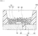
- Fig. 1 is a schematic cross-sectional view showing an example of the light emitting device 100 of an embodiment of the present invention.
- the light emitting device 100 is provided with a molded article 40, a light emitting element 10 and a fluorescent member 50.
- the molded article 40 is integrally composed of a first lead 20, a second lead 30 and a resin part 42 containing a thermoplastic resin or a thermosetting resin.
- the molded article 40 forms a recess part having a bottom face and a side face, and the light emitting element 10 is mounted on the bottom face of the recess part.
- the light emitting element 10 has a pair of positive and negative electrodes, and the pair of positive and negative electrodes each are individually electrically connected to the first lead 20 and the second lead 30 each via a wire 60.
- the light emitting element 10 is covered with the fluorescent member 50.
- the fluorescent member 50 contains, for example, a fluorescent material 70 for wavelength conversion of the light from the light emitting element 10, and a resin. Further, the fluorescent material 70 contains a first fluorescent material 71 and optionally a second fluorescent material 72.
- the first lead 20 and the second lead 30 connected to the pair of positive and negative electrodes of the light emitting element 10 are partly exposed toward the outside of the package to constitute the light emitting device 100. Via these first lead 20 and second lead 30, the light emitting device 100 receives external power to emit light.
- the light emitting element 10 is used as an excitation light source, and preferably has an emission peak wavelength within a range of 380 nm or more and 485 nm or less.
- the range of the emission peak wavelength of the light emitting element 10 is preferably in a range of 390 nm or more and 480 nm or less, more preferably in a range of 420 nm or more and 470 nm or less.
- the aluminate fluorescent material of the first embodiment of the present disclosure is efficiently excited by the excitation light source having an emission spectrum within a range of 380 nm or more and 485 nm or less.
- the optical reflectance thereof from an excitation light source having an emission peak wavelength within a range of 420 nm or more and 470 nm or less is low, that is, the light absorptivity thereof is high and the aluminate fluorescent material can be efficiently excited by the light.
- the aluminate fluorescent material of the first embodiment of the present disclosure can be efficiently excited by the light from the excitation light source having an emission peak wavelength within the above-mentioned wavelength range, and by using the aluminate fluorescent material having such a high emission intensity of this type, the light emitting device 100 that can emit mixed light of the light from the light emitting element 10 and the fluorescence from the fluorescent material 70 can be constructed.
- the half value width of the emission spectrum of the light emitting element 10 is, for example, 30 nm or less.
- the light emitting element 10 uses a semiconductor light emitting element.
- the semiconductor light emitting element as a light source, a stable light emitting device having a high efficiency and a high linearity of output to input and having high mechanical impact resistance can be obtained.
- Examples of the semiconductor light emitting element include a semiconductor light emitting element using a nitride semiconductor (In X Al Y Ga 1-X-Y N, 0 ⁇ X, 0 ⁇ Y, X + Y ⁇ 1).
- the light emitting device 100 includes at least the aluminate fluorescent material of the first embodiment of the present disclosure, and preferably contains the aluminate fluorescent material having a composition represented by the formula (I).
- the first fluorescent material 71 containing the aluminate fluorescent material of the first embodiment of the present disclosure can be contained, for example, in the fluorescent member 50 to cover the light emitting element 10, thereby constituting the light emitting device 100.
- the fluorescent member 50 that contains the first fluorescent material 71 including the aluminate fluorescent material, a part of the light released from the light emitting element 10 is absorbed by the aluminate fluorescent material and is thereby emitted as green light.
- the light emitting element 10 that emits light having an emission spectrum within a wavelength in a range of 380 nm or more and 485 nm or less, especially emitting light having an emission spectrum within a wavelength in a range of 420 nm or more and 470 nm or less, the emitted light can be more effectively utilized. Accordingly, a light emitting device having a high emission efficiency can be provided.
- the content of the first fluorescent material 71 is, for example, in a range of 1 part by mass or more and 50 parts by mass or less relative to the resin (100 parts by mass) and is preferably in a range of 2 parts by mass or more and 40 parts by mass or less.
- the fluorescent member 50 contains the second fluorescent material 72 whose emission peak wavelength differs from that of the first fluorescent material 71.
- the light emitting device 100 is provided with the light emitting element 10 having an emission spectrum within a wavelength range of 380 nm or more and 485 nm or less, and especially emitting light having an emission peak wavelength within a range of 420 nm or more and 470 nm or less, and the first fluorescent material 71 containing the aluminate fluorescent material of the first embodiment of the present disclosure that is excited by the light, and optionally the second fluorescent material 72, and consequently, the light emitting device 100 can have a broad color reproducibility range and good color rendering properties.
- the second fluorescent material 72 may be any one that absorbs light from the light emitting element 10 for wavelength conversion into light having a different wavelength of the first fluorescent material 71.
- Examples thereof include (Ca,Sr,Ba) 2 SiO 4 :Eu, (Y,Gd,Lu) 3 (Ga,Al) 5 O 12 :Ce, (Si,Al) 6 (O,N) 8 :Eu, SrGa 2 S 4 :Eu, K 2 SiF 6 :Mn, (Ba,Ca,Sr) 2 Si 5 N 8 :Eu, CaAlSiN 3 :Eu, (Ca,Sr)AlSiN 3 :Eu, (Ca,Sr,Ba) 8 MgSi 4 O 16 (F,Cl,Br) 2 :Eu, (Y,La) 3 Si 6 N 11 :Ce, Ca 3 Sc 2 Si 3 O 12 :Ce, CaSc 4 O 4 :Ce, etc.
- the second fluorescent material 72 is preferably a red fluorescent material to emit a red color, and preferably absorbs light falling within a wavelength range of 380 nm or more and 485 nm or less, and emits light falling within a wavelength in a range of 610 nm or more and 780 nm or less. Containing the red fluorescent material, the light emitting device can be more favorably applied to lighting systems, liquid crystal display devices, etc.
- the red fluorescent material includes a tetravalent Mn-activated fluoride fluorescent material having a compositional formula represented by K 2 SiF 6 :Mn, a divalent Eu-activated nitride fluorescent material represented by CaSiAlN 3 :Eu, (Ca,Sr)AlSiN 3 :Eu, SrLiAl 3 N 4 :Eu, etc.
- the red fluorescent material is, from the viewpoint of increasing the color purity and broadening the color reproducibility range, preferably a tetravalent Mn-activated fluoride fluorescent material of such that the half value width of the emission spectrum thereof is 20 nm or less.
- the first fluorescent material 71 and optional the second fluorescent material 72 (the two may be simply referred to as "fluorescent material 70" as combined), along with a sealant material, constitute the fluorescent member 50 that covers the light emitting element.
- the sealant material which may be used in the fluorescent member 50 includes a resin, such as a silicone resin, an epoxy resin, etc.
- the total content of the fluorescent material 70 in the fluorescent member 50 may be, for example, in a range of 5 parts by mass or more and 300 parts by mass or less, relative to the resin (100 parts by mass), and is preferably in a range of 10 parts by mass or more and 250 parts by mass or less, even more preferably in a range of 15 parts by mass or more and 230 parts by mass or less, still more preferably in a range of 15 parts by mass or more and 200 parts by mass or less.
- the total content of the fluorescent material in the fluorescent member 50 falls within the range, the light emitted by the light emitting element 10 can be efficiently processed for wavelength conversion by the fluorescent material 70.
- the fluorescent member 50 may further contain a filler, a light diffuser and the like in addition to the sealant material and the fluorescent material 70.
- a filler for example, containing a light diffuser, the member can relieve the directionality from the light emitting element 10 and can therefore enlarge the viewing angle.
- the filler include silica, titanium oxide, zinc oxide, zirconium oxide, alumina, etc.
- the filler content may be, for example, in a range of 1 part by mass or more and 20 parts by mass or less relative to the resin (100 parts by mass).
- the aluminate fluorescent material can be produced using compounds containing elements that constitute the composition of the aluminate fluorescent material.
- the compounds containing elements to constitute the composition of the aluminate fluorescent material include compounds containing aluminum (Al), compounds containing magnesium (Mg), compounds containing manganese (Mn) and one or both of compounds containing barium (Ba) and compounds containing strontium (Sr).
- the aluminum containing compounds include Al-containing oxides, hydroxides, nitrides, oxynitrides, fluorides, chlorides, etc. These compounds may be hydrates.
- an aluminum metal elementary substance or an aluminum alloy may also be used or the metal elementary substance or the alloy may be used for at least a part of the compounds to be used.
- Al-containing compounds include Al 2 O 3 , Al(OH) 3 , AlN, AlON, AlF 3 , AlCl 3 , etc.
- the Al-containing compound is preferably an oxide (Al 2 O 3 ).
- the oxide does not contain any other element than those of the intended composition of the aluminate fluorescent material, and can readily give the fluorescent material having a desired composition.
- residual impurity elements may remain in the resultant fluorescent material, and the residual impurity elements may be killer factors against light emission and the emission intensity would be thereby noticeably lowered.
- the barium containing compounds include Ba-containing oxides, hydroxides, carbonates, nitrates, sulfates, carboxylates, halides, nitrides, etc. These barium containing compounds may be in the form of hydrates. Specific examples thereof include BaO, Ba(OH) 2 ⁇ 8H 2 O, BaCO 3 , Ba(NO 3 ) 2 , BaSO 4 , Ba(OCOH) 2 ⁇ 2H 2 O, Ba(OCOCH 3 ) 2 , BaCl 2 ⁇ 6H 2 O, Ba 3 N 2 , BaNH, etc.
- One alone or two or more kinds of the Ba-containing compounds may be used either singly or as combined.
- a Ba-containing carbonate (BaCO 3 ) is more preferred as it is stable in air, it can readily decompose by heating, any other element than those of the intended composition hardly remain, and it is easy to prevent emission intensity reduction owing to residual impurity elements.
- the strontium containing compounds include Sr-containing oxides, hydroxides, carbonates, nitrates, sulfates, carboxylates, halides, nitrides, etc. These strontium containing compounds may be in the form of hydrates. Specific examples thereof include SrO, Sr(OH) 2 ⁇ 8H 2 O, SrCO 3 , Sr(NO 3 ) 2 ⁇ 4H 2 O, SrSO 4 , Sr(OCOH) 2 ⁇ H 2 O, Sr(OCOCH 3 ) 2 -0.5H 2 O, SrCl 2 -6H 2 O, Sr 3 N 2 , SrNH, etc.
- Sr-containing compounds may be used either singly or as combined.
- carbonates and oxides are preferred.
- a Sr-containing carbonate (SrCO 3 ) is more preferred as it is stable in air, it can readily decompose by heating, any other element than those of the intended composition hardly remain, and it is easy to prevent emission intensity reduction owing to residual impurity elements.
- the magnesium containing compounds include Mg-containing oxides, hydroxides, carbonates, nitrates, sulfates, carboxylates, halides, nitrides, etc. These magnesium containing compounds may be in the form of hydrates. Specific examples thereof include MgO, Mg(OH) 2 , 3MgCO 3 ⁇ Mg(OH) 2 ⁇ 3H 2 O, MgCO 3 ⁇ Mg(OH) 2 ⁇ 2H 2 O, Mg(NO 3 ) 2 ⁇ 6H 2 O, MgSO 4 , Mg(OCOH) 2 ⁇ H 2 O, Mg(OCOCH 3 ) 2 ⁇ 4H 2 O, MgCl 2 , Mg 3 N 2 , MgNH, etc.
- Mg-containing compounds may be used either singly or as combined.
- carbonates and oxides are preferred.
- a Mg-containing oxide (MgO) is more preferred as it is stable in air, it can readily decompose by heating, any other element than those of the intended composition hardly remain, and it is easy to prevent emission intensity reduction owing to residual impurity elements.
- the manganese containing compounds include Mn-containing oxides, hydroxides, carbonates, nitrates, sulfates, carboxylates, halides, nitrides, etc. These manganese containing compounds may be in the form of hydrates. Specific examples thereof include MnO 2, Mn 2 O 2 , Mn 3 O 4 , MnO, Mn(OH) 2 , MnCO 3 , Mn(NO 3 ) 2 , Mn(OCOCH 3 ) 2 ⁇ 2H 2 O, Mn(OCOCH 3 ) 3 ⁇ 2H 2 O, MnCl 2 ⁇ 4H 2 O, etc. One alone or two or more kinds of the Mn-containing compounds may be used either singly or as combined.
- a Mn-containing carbonate (MnCO 3 ) is more preferred as it is stable in air, it can readily decompose by heating, any other element than those of the intended composition hardly remain, and it is easy to prevent emission intensity reduction owing to residual impurity elements.
- a Mg-containing compound, a Mn-containing compound, an Al-containing compound and one or both of a Ba-containing compound and a Sr-containing compound are mixed in such a manner that the aluminate fluorescent material to be produced could have a composition where the molar ratio of Al is taken as 10, the total molar ratio of the first element is a value of a parameter a, the total molar ratio of the second element is a value of a parameter b, the molar ratio of Sr is a product of a value of a parameter m and the value of the parameter a, the molar ratio of Mn is a product of a value of a parameter n and the value of the parameter b, the value of the parameters a and b are values satisfying the following requirement (1), the value of the parameter m is a value satisfying the following requirement (2), and the value of the parameter n is a value satisfying the following requirement (3),
- the element-containing compounds are mixed in such a manner that the value of the parameters a and b could be a value satisfying the following requirement (4). 0.7 ⁇ b ⁇ a ⁇ 0.5 b + 0.5 ⁇ 1.0
- the crystal structure of the aluminate fluorescent material can be stable and the emitting intensity of the resultant aluminate fluorescent material can be high.
- the value of the parameter n satisfies the requirement of 0.4 ⁇ n ⁇ 0.6, or the product of the value of the parameter b and the value of the parameter n (b ⁇ n) is a value satisfying the requirement of 0.3 ⁇ b ⁇ n ⁇ 0.6.
- the Mn activation amount can fall within an optimum range, and light absorption in a near-UV to blue region contained in the excitation light source can be promoted, and consequently, concentration quenching which may be caused by too much Mn activation can be prevented, the emission intensity can be increased, and the emission intensity through photoexcitation in a near UV to blue region can be further increased.
- the raw material mixture may optionally contain a flux of halide or the like.
- a flux of halide or the like In the raw material mixture containing a flux, reaction between the raw materials can be promoted and solid-phase reaction can go on more uniformly. This is because the temperature of heat treatment for the raw material mixture would be nearly the same as the liquid phase formation temperature for halides and the like to be used as the flux, or would be higher than the liquid phase formation temperature, and therefore the reaction could be promoted.
- the halides includes fluorides, chlorides and others of rare earth metals, alkaline earth metals, alkali metals, etc.
- the flux may be added as the compound to provide the composition of the intended aluminate fluorescent material.
- Specific examples of the flux include barium fluoride (BaF 2 ), strontium fluoride (SrF 2 ), magnesium fluoride (MgF 2 ), aluminum fluoride (AlF 3 ), manganese fluoride (MnF 2 ), calcium fluoride (CaF 2 ), etc.
- Magnesium fluoride (MgF 2 ) is preferred. This is because, by using magnesium fluoride as the flux, the crystal structure is stabilized.
- the flux content is preferably 10% by mass or less, based on the raw material mixture (100% by mass), more preferably 5% by mass or less, and is preferably 0.1% by mass or more.
- the flux content falls within the range, difficulty in formation of crystal structure owing to shortage of the flux to cause grain growth failure could be evaded, and difficulty in formation of crystal structure owing to excessive flux could also be evaded.
- the compounds each containing the intended element are weighed to be in a desired blending ratio, and then ground and mixed using, for example, a dry-process grinding machine such as a ball mill, a shaking mill, a hammer mill, a roll mill, a jet mill, or may be ground and mixed using a mortar and a pestle, etc.
- a dry-process grinding machine such as a ball mill, a shaking mill, a hammer mill, a roll mill, a jet mill, or may be ground and mixed using a mortar and a pestle, etc.
- the compounds may be mixed using a mixing machine such as a ribbon blender, a Henschel mixer, a V-shaped blender, or may be ground and mixed using both the dry-process grind machine and the mixing machine.
- the mixing may be dry-process mixing, or may also be wet-process mixing with a solvent added to the system. Dry-process mixing is preferred. This is because the processing time may be shortened more in dry-process mixing than in wet-process mixing,
- the raw material mixture may be heat-treated in a crucible, a boat formed of a carbonaceous material such as graphite or the like, or a material of boron nitride (BN), aluminum oxide (alumina), tungsten (W), molybdenum (Mo), etc.
- a crucible a boat formed of a carbonaceous material such as graphite or the like, or a material of boron nitride (BN), aluminum oxide (alumina), tungsten (W), molybdenum (Mo), etc.
- the heat treatment temperature for the raw material mixture is, from the viewpoint of the stability of the crystal structure, preferably in a range of 1,000°C or higher and 1,800°C or lower, more preferably in a range of 1,100°C or higher and 1,750°C or lower, even more preferably in a range of 1,200°C or higher and 1,700°C or lower, especially more preferably in a range of 1,300°C or higher and 1,650°C or lower.
- the heat treatment time differs depending on the heating speed, the heat treatment atmosphere and others. After the system has reached the heat treatment temperature, it is kept as such preferably for 1 hour or more, more preferably 2 hours or more, even more preferably 3 hours or more, and preferably 20 hours or less, more preferably 18 hours or less, even more preferably 15 hours or less.
- the atmosphere for heat treatment for the raw material mixture may be an inert atmosphere of argon, nitrogen, a reductive atmosphere containing hydrogen, or an oxidative atmosphere such as air, etc.
- the raw material mixture is heat-treated in a reductive nitrogen atmosphere to give a fluorescent material.
- the atmosphere for heat treatment for the raw material mixture is a nitrogen atmosphere containing hydrogen gas.
- the raw material mixture can be more reactive in an atmosphere having a high reductive power such as an atmosphere containing hydrogen and nitrogen, and can be heat-treated therein under an atmospheric pressure without pressurization.
- an atmosphere having a high reductive power such as an atmosphere containing hydrogen and nitrogen
- the heat treatment for example, an electric furnace, a gas furnace or the like may be used.
- the resultant fluorescent material may be post-treated for wet dispersion, wet-process sieving, dewatering, drying, dry-process sieving.
- a fluorescent material having a desired mean particle size can be obtained.
- the fluorescent material after post treatment is dispersed in a solvent, then the dispersed fluorescent material is put on a sieve, and while a solvent flow is given thereto along with various shaking given thereto via the sieve, the baked product is led to pass through a mesh for wet-process sieving, and then dewatered, dried and dry-sieved to give a fluorescent material having a desired mean particle size.
- dispersing the fluorescent material after heat treatment in a medium By dispersing the fluorescent material after heat treatment in a medium, impurities such as baked residues of flux as well as unreacted components of the raw materials can be removed.
- dispersion media such as alumina balls, zirconia balls and the like may be used.
- the resultant raw material mixture was filled in an alumina crucible and the crucible was closed with a lid, and in a mixed atmosphere of 3 vol% of H 2 and 97 vol% of N 2 , heat treatment was performed at 1,500°C for 5 hours to give an aluminate fluorescent material.
- An aluminate fluorescent material was obtained in the same manner as in Example 1 except that, as raw material, 37.8 g of BaCO 3 , 28.4 g of SrCO 3 , 205.6 g of Al 2 O 3 , 7.6 g of MgO and 18.1 g of MnCO 3 were weighed so that the blending molar ratio could have a composition represented by (Ba 0.5 Sr 0.5 ) 0.95 (Mg 0.6 Mn 0.4 ) 0.93 Al 10 O 16.88 , and as a flux, 2.5 g of MgF 2 was added.
- An aluminate fluorescent material was obtained in the same manner as in Example 1 except that, as raw material, 37.1 g of BaCO 3 , 27.8 g of SrCO 3 , 201.6 g of Al 2 O 3 , 4.4 g of MgO and 26.6 g of MnCO 3 were weighed so that the blending molar ratio could have a composition represented by (Ba 0.5 Sr 0.5 ) 0.95 (Mg 0.4 Mn 0.6 ) 0.93 Al 10 O 16.88 , and as a flux, 2.5 g of MgF 2 was added.
- An aluminate fluorescent material was obtained in the same manner as in Example 1 except that, as raw material, 37.2 g of BaCO 3 , 27.9 g of SrCO 3 , 208.6 g of Al 2 O 3 , 6.9 g of MgO and 16.8 g of MnCO 3 were weighed so that the blending molar ratio could have a composition represented by (Ba 0.5 Sr 0.5 ) 0.92 (Mg 0.6 Mn 0.4 ) 0.85 Al 10 O 16.77 , and as a flux, 2.5 g of MgF 2 was added.
- An aluminate fluorescent material was obtained in the same manner as in Example 1 except that, as raw material, 36.2 g of BaCO 3 , 27.2 g of SrCO 3 , 203.0 g of Al 2 O 3 , 2.5 g of MgO and 28.6 g of MnCO 3 were weighed so that the blending molar ratio could have a composition represented by (Ba 0.5 Sr 0.5 ) 0.92 (Mg 0.3 Mn 0.7 ) 0.85 Al 10 O 16.77 , and as a flux, 2.5 g of MgF 2 was added.
- An aluminate fluorescent material was obtained in the same manner as in Example 1 except that, as raw material, 38.6 g of BaCO 3 , 29.0 g of SrCO 3 , 209.8 g of Al 2 O 3 , 10.9 g of MgO and 9.2 g of MnCO 3 were weighed so that the blending molar ratio could have a composition represented by (Ba 0.5 Sr 0.5 ) 0.95 (Mg 0.8 Mn 0.2 ) 0.93 Al 10 O 16.88 , and as a flux, 2.5 g of MgF 2 was added.
- An aluminate fluorescent material was obtained in the same manner as in Example 1 except that, as raw material, 38.3 g of BaCO 3 , 28.8 g of SrCO 3 , 197.7 g of Al 2 O 3 , 4.8 g of MgO and 28.1 g of MnCO 3 were weighed so that the blending molar ratio could have a composition represented by (Ba 0.5 Sr 0.5 ) 1.00 (Mg 0.4 Mn 0.6 ) 1.00 Al 10 O 17.00 , and as a flux, 2.4 g of MgF 2 was added.
- An aluminate fluorescent material was obtained in the same manner as in Example 1 except that, as raw material, 36.4 g of BaCO 3 , 27.3 g of SrCO 3 , 197.8 g of Al 2 O 3 , 1.4 g of MgO and 34.8 g of MnCO 3 were weighed so that the blending molar ratio could have a composition represented by (Ba 0.5 Sr 0.5 ) 0.95 (Mg 0.2 Mn 0.8 ) 0.93 Al 10 O 16.88 , and as a flux, 2.4 g of MgF 2 was added.
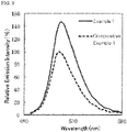
- the emission characteristics of the fluorescent materials of Examples and Comparative Examples were measured. Using a quantum efficiency measurement system (QE-2000 manufactured by Otsuka Electronics Co., Ltd.), each fluorescent material was irradiated with light having an excitation wavelength of 450 nm to measure the emission spectrum thereof at room temperature (25°C ⁇ 5°C). The emission intensity (%) of the resultant emission spectrum was determined. The relative emission intensity was calculated based on the emission intensity 100% of the fluorescent material of Comparative Example 1. The results are shown in Table 1. Fig. 2 shows the emission spectrum of the relative emission intensity (%) to wavelength of the aluminate fluorescent materials of Example 1 and Comparative Example 1.
- the wavelength at which the resultant emission spectrum of the fluorescent material of Examples and Comparative Examples was maximum was determined as an emission peak wavelength (nm). The results are shown in Table 1.
- a sample of the fluorescent material of Examples and Comparative Examples was irradiated with light from an excitation light source a halogen lamp, at room temperature (25°C ⁇ 5°C), and the wavelength of the spectroscope on the excitation side and the fluorescence side was scanned in combination to measure the reflected light.
- the proportion of the reflected light relative to the light having an excitation wavelength of 450 nm is shown in Table 1 as a reflectance (%) based on the reflectance of CaHPO 4 ,
- the reflection to wavelength of the fluorescent material of the Examples and the fluorescent material of Comparative Example 1 is shown in Fig. 3 as a reflection spectrum thereof.
- Example 1 Compositional Ratio a b m n b ⁇ n Optical Characteristics 450nm Reflectance (%) Relative Emission Intensity (%) Emission Peak Wavelength (nm) FWHM (nm)
- Example 2 (Ba 0.5 Sr 0.5 ) 0.95 (Mg 0.6 Mn 0.4 ) 0.93 Al 10 O 16.88 0.95 0.93 0.5 0.4 0.372 141 517 28 79.9
- Example 3 (Ba 0.5 Sr 0.5 ) 0.95 (Mg 0.4 Mn 0.6 ) 0.93 Al 10 O 16.88 0.95 0.93 0.5 0.6 0.558 135 518 29 76.6
- Example 4 (Ba 0.5 Sr 0.5 ) 0.92 (Mg 0.6 Mn 0.4 ) 0.85 Al 10 O 16.77 0.92 0.
- the value of the parameters a, b, m and n satisfies the requirements (1) to (3) when the molar ratio Al is taken as 10.
- the aluminate fluorescent materials of these Examples 1 to 5 had a higher relative emission intensity owing to excitation of blue light having an emission peak wavelength of 450 nm, than those of Comparative Examples 1 to 3.
- the value of the parameter n indicating the molar ratio of Mn in the second element (Mg and Mn) satisfies 0.4 ⁇ n ⁇ 0.6
- the product of the value of the parameter n indicating the molar ratio of Mn and the value of the parameter b (b ⁇ n) satisfies the requirement of 0.3 ⁇ b ⁇ n ⁇ 0.6
- the relative emission intensity of the aluminate fluorescent materials was 135% or more and was extremely high owing to excitation of blue light having an emission peak wavelength of 450 nm.
- the reflectance of the aluminate fluorescent materials of Examples 1 to 5 to the excitation light, blue light having an emission peak wavelength of 450 nm was 80% or less and was low. From these results, it is confirmed that the aluminate fluorescent materials of Examples 1 to 5 greatly absorb a part of the excitation light, blue light having an emission peak wavelength of 450 nm, and exhibits fluorescence at a high emission intensity.
- the value of the parameter n indicating the molar ratio of Mn in the second element (Mg and Mn) did not satisfy the requirement (3), 0.4 ⁇ n ⁇ 0.7.
- the reflectance was more than 80%, and was higher than the reflectance of the aluminate fluorescent materials of Examples 1 to 5, in other words, the absorbance of the excitation light having an emission peak wavelength of 450 nm of the former was small and the relative emission intensity of the former was lower than that of the aluminate fluorescent materials of Examples 1 to 5.
- the half value width of the emission peak in the emission spectrum of the aluminate fluorescent materials of Examples 1 to 5 was less than 30 nm and was narrow.
- the aluminate fluorescent materials of Examples 1 to 5 emitted light whose emission peak wavelength falls within a range of 516 nm to 518 nm, through excitation of blue light having an emission peak intensity of 450 nm.
- the relative emission intensity at the emission peak wavelength of the aluminate fluorescent material of Example 1 was higher than the relative emission intensity of Comparative Example 1.
- the reflection spectrum within a range of 420 nm or more and 470 nm or less of the aluminate fluorescent material of Example 1 was lower than the reflection spectrum within the same range of the aluminate fluorescent material of Comparative Example 1, and in particular, the absorption of excitation light having a wavelength of 420 nm or more and 470 nm or less of the former is high, and it is confirmed that the aluminate fluorescent material of Example 1 absorbed the excitation light falling within the wavelength range and emitted fluorescence at a high emission intensity.
- an aluminate fluorescent material having a high emission intensity as a green emitting fluorescent material that is excited with light falling in a near-UV to blue region.
- the light emitting device using the aluminate fluorescent material can be used in a wide range of fields of general lighting, in-car lighting, displays, backlights for liquid crystals, traffic lights, lighting switches, etc.
- the aluminate fluorescent material of one embodiment of the present disclosure has a high emission intensity, has a narrow half value width of an emission peak and has a high color purity, and therefore can broaden the color reproducibility range, and is favorably usable as a backlight source for liquid crystals.
Landscapes
- Chemical & Material Sciences (AREA)
- Inorganic Chemistry (AREA)
- Engineering & Computer Science (AREA)
- Materials Engineering (AREA)
- Organic Chemistry (AREA)
- Luminescent Compositions (AREA)
Abstract
Description
- This application claims benefit of Japanese Patent Application No.
2016-115062, filed on June 9, 2016 2017-054756, filed on March 21, 2017 - The present invention relates to an aluminate fluorescent material, a light emitting device using the same and a method of producing an aluminate fluorescent material.
- Various light emitting devices that emit white light, bulb color light, orange light by combination of a light emitting diode (LED) and a fluorescent material have been developed. In these light emitting devices, a desired luminescent color can be obtained according to the principle of light color mixing. As a light emitting device that emits white light, there is well known a light emitting device using a light emitting element that emits blue color and a fluorescent material that emits yellow color. The light emitting device using a light emitting element that emits blue color and a fluorescent material that emits yellow color or the like is desired to be used in a wide range of fields of general lighting, in-car lighting, displays, backlights for liquid crystals, etc. Among these, the fluorescent material for use in a light emitting device for backlights for liquid crystals is required to have a high color purity in addition to a high emission efficiency for reproducing colors in a broad range on the chromaticity coordinate system. In particular, the fluorescent material for use in a light emitting device for backlights for liquid crystals is desired to have a narrow full width at a half maximum (FWHM - hereinafter this is referred to as "half value width") of the emission peak in the emission spectrum thereof and to have a high color purity, from the viewpoint of realizing a broad color reproducibility range.
- Japanese Unexamined Patent Publication No.
2004-155907 2004-155907 - However, the manganese-activated aluminate fluorescent material disclosed in Japanese Unexamined Patent Publication No.
2004-155907 - Consequently, an object of the present invention is to provide an aluminate fluorescent material capable of having a high emission intensity through photoexcitation in a near-UV to blue region, a light emitting device, and a method for producing an aluminate fluorescent material.
- For solving the above-mentioned problem, the present disclosure includes the following aspects.
- A first embodiment of the present disclosure relates to an aluminate fluorescent material having a composition containing a first element that contains one or more elements selected from Ba and Sr, and a second element that contains Mg and Mn, wherein in the composition of the aluminate fluorescent material, when a molar ratio of Al is taken as 10, a total molar ratio of the first element is a value of a parameter a, a total molar ratio of the second element is a value of a parameter b, a molar ratio of Sr is a product of a value of a parameter m and the value of a parameter a, a molar ratio of Mn is a product of a value of a parameter n and the value of a parameter b, the value of a parameters a and b satisfy the following requirement (1), the value of a parameter m satisfies the following requirement (2), and the value of a parameter n satisfies the following requirement (3):


- A second embodiment of the present disclosure relates to a light emitting device including the aluminate fluorescent material and an excitation light source.
- A third embodiment of the present disclosure relates to a method of producing an aluminate fluorescent material, which includes mixing and heat-treating compounds that contain elements so as to provide a composition containing a first element that contains one or more elements selected from Ba and Sr, a second element that contains Mg and Mn, and Al and O, wherein in the composition, when a molar ratio of Al is taken as 10, a total molar ratio of the first element (Ba, Sr) is a value of a parameter a, a total molar ratio of the second element (Mg and Mn) is a value of a parameter b, a molar ratio of Sr is a product of a value of a parameter m and the value of a parameter a, a molar ratio of Mn is a product of a value of a parameter n and the value of a parameter b, the value of a parameters a and b satisfy the following requirement (1), the value of a parameter m satisfies the following requirement (2), and the value of a parameter n satisfies the following requirement (3):


- In accordance with an embodiment of the present disclosure, it is possible to provide an aluminate fluorescent material having a high emission intensity through excitation by light having an emission spectrum in a range of 380 nm or more and 485 nm or less, a light emitting device using the same and a method of producing an aluminate fluorescent material.
-
-
Fig. 1 is a schematic cross-sectional view showing one example of a light emitting device. -
Fig. 2 is a diagram showing light emission spectra of the aluminate fluorescent materials of Example 1 and Comparative Example 1. -
Fig. 3 is a diagram showing reflection spectra of the aluminate fluorescent materials of Example 1 and Comparative Example 1. - The aluminate fluorescent material, the light emitting device and the production method for an aluminate fluorescent material of the present invention are described on a basis of the embodiments and examples. The embodiments shown below are exemplifications for exemplifying the technical idea of the present invention, and the present invention is not limited to the aluminate material, the light emitting device and the production method for an aluminate fluorescent material described below. The relationship between the color name and the chromaticity coordinate, and the relationship between the wavelength range of light and the color name of monochromatic light in accordance with JIS Z8110. The "fluorescent" means the emission of light by a substance that has absorbed light or other electromagnetic radiation.
- The aluminate fluorescent material of the first aspect of the present invention is an aluminate fluorescent material having a composition containing a first element that contains one or more elements selected from Ba and Sr, the first element preferably consisting of one or more elements selected from Ba and Sr, and a second element that contains Mg and Mn, the second element preferably consisting of Mg and Mn, wherein in the composition of the aluminate fluorescent material, when a molar ratio of Al is taken as 10, a total molar ratio of the first element is a value of a parameter a, a total molar ratio of the second element is a value of a parameter b, a molar ratio of Sr is a product of a value of a parameter m and the value of the parameter a, a molar ratio of Mn is a product of a value of a parameter n and the value of the parameter b, the value of a parameters a and b satisfy the following requirement (1), the value of the parameter m satisfies the following requirement (2), and the value of the parameter n satisfies the following requirement (3):


- In the composition of the aluminate fluorescent material, the value of the parameter a is a total molar ratio of Ba and Sr. In the composition of the aluminate fluorescent material, when the value of the parameter a is not a value satisfying the requirement (1), the crystal structure may be unstable and the emission intensity may lower. In the composition of the aluminate fluorescent material, the value of the parameter b is a total molar ratio of Mg and Mn. In the composition of the aluminate fluorescent material, when the value of the parameter b is 0.5 or less, the crystal structure may be unstable and the emission intensity may lower.
- In the composition of the aluminate fluorescent material, the value of the parameter a and the value of the parameter b are preferably values satisfying the following requirement (4).

- In the composition of the aluminate fluorescent material, when the value of the parameter b is a value of more than 0.7, the crystal structure of the aluminate fluorescent material can be stabilized more and the emission intensity of the aluminate fluorescent material can be higher.
- In the composition of the aluminate fluorescent material, the value of the parameter m indicates the molar ratio of Sr when the total molar ratio of Ba and Sr of the first element is 1, and the first element may be all Ba or may be all Sr.
- In the composition of the aluminate fluorescent material, the value of the parameter n indicates the molar ratio of Mn when the total molar ratio of Mg and Mn of the second element is 1. In the composition of the aluminate fluorescent material, when the value of a parameter n indicating the molar ratio of Mn among Mg and Mn of the second element is less than 0.4 or more than 0.7, the emission intensity through photoexcitation in a near UV to blue region may lower.
- In the composition of the aluminate fluorescent material, the value of the parameter n is preferably a value satisfying a requirement of 0.4 ≤ n ≤ 0.6.
- In the composition of the aluminate fluorescent material, when the value of the parameter n is the value satisfying the requirement of 0.4 ≤ n ≤ 0.6, the emission intensity may be increased more and the emission intensity of the aluminate fluorescent material through photoexcitation in a near UV to blue region can be higher.
- In the composition of the aluminate fluorescent material, the product of the value of the parameter n indicating the molar ratio of Mn among Mg and Mn and the value of the parameter b (b × n) is preferably a value satisfying a requirement of 0.3 < b × n < 0.6.
- For example, it is considered that the reason why the emission intensity through photoexcitation in a near-UV to blue region of the manganese-activated aluminate fluorescent material disclosed in Japanese Unexamined Patent Publication No.
2004-155907 - Preferably, the aluminate fluorescent material has a composition represented by the following formula (I). The aluminate fluorescent material having a composition represented by the formula (I) has a high emission intensity and through photoexcitation in a near-UV to blue region, the emission intensity thereof can be higher.
(Ba1-m,Srm)a(Mg1-n,Mnn)bAl10O15+a+b (I)
wherein, a, b, m and n each are a number satisfying 0.5 < b < a ≤ 0.5b + 0.5 < 1.0, 0 ≤ m ≤ 1.0, and 0.4 ≤ n ≤ 0.7. - Regarding the aluminate fluorescent material of the first embodiment of the present disclosure, the half value width of the emission peak in the emission spectrum thereof, as excited with light in a near-UV to blue region, for example, with light having an emission peak wavelength of 450 nm, is preferably 45 nm or less, more preferably 40 nm or less, even more preferably 30 nm or less. As a fluorescent material capable of emitting green light by photoexcitation in a near-UV to blue region, for example, there is known a β-salon fluorescent material doped with europium (Eu). The half value width of the emission peak in the emission spectrum of the β-sialon fluorescent material, when irradiated with light having an excitation wavelength of 450 nm, is 50 nm or so, that is, the half value width of the aluminate fluorescent material of the first embodiment of the present disclosure is narrower. The aluminate fluorescent material has a narrow half value width of the emission peak in the emission spectrum, and therefore has a high color purity. For example, when the light emitting device including the aluminate fluorescent material is used as a backlight for liquid crystals, the color reproducibility range can be broadened.
- The aluminate fluorescent material of the first embodiment of the present disclosure is activated by manganese (Mn) and emits green light through photoexcitation in a near-UV to blue region. Specifically, the aluminate fluorescent material absorbs light falling within a wavelength range of 380 nm to 485 nm, and the emission peak wavelength in the emission spectrum thereof falls preferably in a range of 485 nm or more and 570 nm or less, more preferably in a range of 495 nm or more and 560 nm or less, even more preferably in a range of 505 nm or more and 550 nm or less.
- One example of a light emitting device, which is the second embodiment of the present disclosure and which includes the aluminate fluorescent material of the first embodiment of the present disclosure, is described with reference to the drawing attached hereto.
Fig. 1 is a schematic cross-sectional view showing an example of thelight emitting device 100 of an embodiment of the present invention. - The
light emitting device 100 is provided with a moldedarticle 40, alight emitting element 10 and afluorescent member 50. The moldedarticle 40 is integrally composed of afirst lead 20, asecond lead 30 and aresin part 42 containing a thermoplastic resin or a thermosetting resin. The moldedarticle 40 forms a recess part having a bottom face and a side face, and thelight emitting element 10 is mounted on the bottom face of the recess part. Thelight emitting element 10 has a pair of positive and negative electrodes, and the pair of positive and negative electrodes each are individually electrically connected to thefirst lead 20 and thesecond lead 30 each via awire 60. Thelight emitting element 10 is covered with thefluorescent member 50. Thefluorescent member 50 contains, for example, afluorescent material 70 for wavelength conversion of the light from thelight emitting element 10, and a resin. Further, thefluorescent material 70 contains a firstfluorescent material 71 and optionally a secondfluorescent material 72. Thefirst lead 20 and thesecond lead 30 connected to the pair of positive and negative electrodes of thelight emitting element 10 are partly exposed toward the outside of the package to constitute thelight emitting device 100. Via thesefirst lead 20 andsecond lead 30, thelight emitting device 100 receives external power to emit light. - The
light emitting element 10 is used as an excitation light source, and preferably has an emission peak wavelength within a range of 380 nm or more and 485 nm or less. The range of the emission peak wavelength of thelight emitting element 10 is preferably in a range of 390 nm or more and 480 nm or less, more preferably in a range of 420 nm or more and 470 nm or less. The aluminate fluorescent material of the first embodiment of the present disclosure is efficiently excited by the excitation light source having an emission spectrum within a range of 380 nm or more and 485 nm or less. Regarding the aluminate fluorescent material, in particular, the optical reflectance thereof from an excitation light source having an emission peak wavelength within a range of 420 nm or more and 470 nm or less is low, that is, the light absorptivity thereof is high and the aluminate fluorescent material can be efficiently excited by the light. The aluminate fluorescent material of the first embodiment of the present disclosure can be efficiently excited by the light from the excitation light source having an emission peak wavelength within the above-mentioned wavelength range, and by using the aluminate fluorescent material having such a high emission intensity of this type, thelight emitting device 100 that can emit mixed light of the light from thelight emitting element 10 and the fluorescence from thefluorescent material 70 can be constructed. - The half value width of the emission spectrum of the
light emitting element 10 is, for example, 30 nm or less. - Preferably, the
light emitting element 10 uses a semiconductor light emitting element. Using the semiconductor light emitting element as a light source, a stable light emitting device having a high efficiency and a high linearity of output to input and having high mechanical impact resistance can be obtained. - Examples of the semiconductor light emitting element include a semiconductor light emitting element using a nitride semiconductor (InXAlYGa1-X-YN, 0 ≤ X, 0 ≤ Y, X + Y ≤ 1).
- The
light emitting device 100 includes at least the aluminate fluorescent material of the first embodiment of the present disclosure, and preferably contains the aluminate fluorescent material having a composition represented by the formula (I). - The first
fluorescent material 71 containing the aluminate fluorescent material of the first embodiment of the present disclosure can be contained, for example, in thefluorescent member 50 to cover thelight emitting element 10, thereby constituting thelight emitting device 100. In thelight emitting device 100 in which thelight emitting element 10 is covered by thefluorescent member 50 that contains the firstfluorescent material 71 including the aluminate fluorescent material, a part of the light released from thelight emitting element 10 is absorbed by the aluminate fluorescent material and is thereby emitted as green light. Using thelight emitting element 10 that emits light having an emission spectrum within a wavelength in a range of 380 nm or more and 485 nm or less, especially emitting light having an emission spectrum within a wavelength in a range of 420 nm or more and 470 nm or less, the emitted light can be more effectively utilized. Accordingly, a light emitting device having a high emission efficiency can be provided. - The content of the first
fluorescent material 71 is, for example, in a range of 1 part by mass or more and 50 parts by mass or less relative to the resin (100 parts by mass) and is preferably in a range of 2 parts by mass or more and 40 parts by mass or less. - Preferably, the
fluorescent member 50 contains the secondfluorescent material 72 whose emission peak wavelength differs from that of the firstfluorescent material 71. For example, thelight emitting device 100 is provided with thelight emitting element 10 having an emission spectrum within a wavelength range of 380 nm or more and 485 nm or less, and especially emitting light having an emission peak wavelength within a range of 420 nm or more and 470 nm or less, and the firstfluorescent material 71 containing the aluminate fluorescent material of the first embodiment of the present disclosure that is excited by the light, and optionally the secondfluorescent material 72, and consequently, thelight emitting device 100 can have a broad color reproducibility range and good color rendering properties. - The second
fluorescent material 72 may be any one that absorbs light from thelight emitting element 10 for wavelength conversion into light having a different wavelength of the firstfluorescent material 71. Examples thereof include (Ca,Sr,Ba)2SiO4:Eu, (Y,Gd,Lu)3(Ga,Al)5O12:Ce, (Si,Al)6(O,N)8:Eu, SrGa2S4:Eu, K2SiF6:Mn, (Ba,Ca,Sr)2Si5N8:Eu, CaAlSiN3:Eu, (Ca,Sr)AlSiN3:Eu, (Ca,Sr,Ba)8MgSi4O16(F,Cl,Br)2:Eu, (Y,La)3Si6N11:Ce, Ca3Sc2Si3O12:Ce, CaSc4O4:Ce, etc. - In the case where the
fluorescent member 50 further contains the secondfluorescent material 72, the secondfluorescent material 72 is preferably a red fluorescent material to emit a red color, and preferably absorbs light falling within a wavelength range of 380 nm or more and 485 nm or less, and emits light falling within a wavelength in a range of 610 nm or more and 780 nm or less. Containing the red fluorescent material, the light emitting device can be more favorably applied to lighting systems, liquid crystal display devices, etc. - The red fluorescent material includes a tetravalent Mn-activated fluoride fluorescent material having a compositional formula represented by K2SiF6:Mn, a divalent Eu-activated nitride fluorescent material represented by CaSiAlN3:Eu, (Ca,Sr)AlSiN3:Eu, SrLiAl3N4:Eu, etc. Among these, the red fluorescent material is, from the viewpoint of increasing the color purity and broadening the color reproducibility range, preferably a tetravalent Mn-activated fluoride fluorescent material of such that the half value width of the emission spectrum thereof is 20 nm or less.
- The first
fluorescent material 71 and optional the second fluorescent material 72 (the two may be simply referred to as "fluorescent material 70" as combined), along with a sealant material, constitute thefluorescent member 50 that covers the light emitting element. The sealant material which may be used in thefluorescent member 50 includes a resin, such as a silicone resin, an epoxy resin, etc. - The total content of the
fluorescent material 70 in thefluorescent member 50 may be, for example, in a range of 5 parts by mass or more and 300 parts by mass or less, relative to the resin (100 parts by mass), and is preferably in a range of 10 parts by mass or more and 250 parts by mass or less, even more preferably in a range of 15 parts by mass or more and 230 parts by mass or less, still more preferably in a range of 15 parts by mass or more and 200 parts by mass or less. When the total content of the fluorescent material in thefluorescent member 50 falls within the range, the light emitted by thelight emitting element 10 can be efficiently processed for wavelength conversion by thefluorescent material 70. - The
fluorescent member 50 may further contain a filler, a light diffuser and the like in addition to the sealant material and thefluorescent material 70. For example, containing a light diffuser, the member can relieve the directionality from thelight emitting element 10 and can therefore enlarge the viewing angle. Examples of the filler include silica, titanium oxide, zinc oxide, zirconium oxide, alumina, etc. In the case where thefluorescent member 50 contains a filler, the filler content may be, for example, in a range of 1 part by mass or more and 20 parts by mass or less relative to the resin (100 parts by mass). - Next, as the third embodiment of the present disclosure, a method of producing the aluminate fluorescent material of the first embodiment of the present disclosure is described. The aluminate fluorescent material can be produced using compounds containing elements that constitute the composition of the aluminate fluorescent material.
- The compounds containing elements to constitute the composition of the aluminate fluorescent material include compounds containing aluminum (Al), compounds containing magnesium (Mg), compounds containing manganese (Mn) and one or both of compounds containing barium (Ba) and compounds containing strontium (Sr).
- The aluminum containing compounds include Al-containing oxides, hydroxides, nitrides, oxynitrides, fluorides, chlorides, etc. These compounds may be hydrates. As the aluminum-containing compound, an aluminum metal elementary substance or an aluminum alloy may also be used or the metal elementary substance or the alloy may be used for at least a part of the compounds to be used.
- Specific examples of the Al-containing compounds include Al2O3, Al(OH)3, AlN, AlON, AlF3, AlCl3, etc. One alone or two or more kinds of the Al-containing compounds may be used either singly or as combined. The Al-containing compound is preferably an oxide (Al2O3). As compared with any other material, the oxide does not contain any other element than those of the intended composition of the aluminate fluorescent material, and can readily give the fluorescent material having a desired composition. In addition, in the case where a compound having any other element than those to be the intended composition is used, residual impurity elements may remain in the resultant fluorescent material, and the residual impurity elements may be killer factors against light emission and the emission intensity would be thereby noticeably lowered.
- The barium containing compounds include Ba-containing oxides, hydroxides, carbonates, nitrates, sulfates, carboxylates, halides, nitrides, etc. These barium containing compounds may be in the form of hydrates. Specific examples thereof include BaO, Ba(OH)2·8H2O, BaCO3, Ba(NO3)2, BaSO4, Ba(OCOH)2·2H2O, Ba(OCOCH3)2, BaCl2·6H2O, Ba3N2, BaNH, etc. One alone or two or more kinds of the Ba-containing compounds may be used either singly or as combined. Among these, from the viewpoint of easiness in handling, carbonates and oxides are preferred. A Ba-containing carbonate (BaCO3) is more preferred as it is stable in air, it can readily decompose by heating, any other element than those of the intended composition hardly remain, and it is easy to prevent emission intensity reduction owing to residual impurity elements.
- The strontium containing compounds include Sr-containing oxides, hydroxides, carbonates, nitrates, sulfates, carboxylates, halides, nitrides, etc. These strontium containing compounds may be in the form of hydrates. Specific examples thereof include SrO, Sr(OH)2·8H2O, SrCO3, Sr(NO3)2·4H2O, SrSO4, Sr(OCOH)2·H2O, Sr(OCOCH3)2-0.5H2O, SrCl2-6H2O, Sr3N2, SrNH, etc. One alone or two or more kinds of the Sr-containing compounds may be used either singly or as combined. Among these, from the viewpoint of easiness in handling, carbonates and oxides are preferred. A Sr-containing carbonate (SrCO3) is more preferred as it is stable in air, it can readily decompose by heating, any other element than those of the intended composition hardly remain, and it is easy to prevent emission intensity reduction owing to residual impurity elements.
- The magnesium containing compounds include Mg-containing oxides, hydroxides, carbonates, nitrates, sulfates, carboxylates, halides, nitrides, etc. These magnesium containing compounds may be in the form of hydrates. Specific examples thereof include MgO, Mg(OH)2, 3MgCO3·Mg(OH)2·3H2O, MgCO3·Mg(OH)2·2H2O, Mg(NO3)2·6H2O, MgSO4, Mg(OCOH)2·H2O, Mg(OCOCH3)2·4H2O, MgCl2, Mg3N2, MgNH, etc. One alone or two or more kinds of the Mg-containing compounds may be used either singly or as combined. Among these, from the viewpoint of easiness in handling, carbonates and oxides are preferred. A Mg-containing oxide (MgO) is more preferred as it is stable in air, it can readily decompose by heating, any other element than those of the intended composition hardly remain, and it is easy to prevent emission intensity reduction owing to residual impurity elements.
- The manganese containing compounds include Mn-containing oxides, hydroxides, carbonates, nitrates, sulfates, carboxylates, halides, nitrides, etc. These manganese containing compounds may be in the form of hydrates. Specific examples thereof include MnO2, Mn2O2, Mn3O4, MnO, Mn(OH)2, MnCO3, Mn(NO3)2, Mn(OCOCH3)2·2H2O, Mn(OCOCH3)3·2H2O, MnCl2·4H2O, etc. One alone or two or more kinds of the Mn-containing compounds may be used either singly or as combined. Among these, from the viewpoint of easiness in handling, carbonates and oxides are preferred. A Mn-containing carbonate (MnCO3) is more preferred as it is stable in air, it can readily decompose by heating, any other element than those of the intended composition hardly remain, and it is easy to prevent emission intensity reduction owing to residual impurity elements.
- In the method of producing the aluminate fluorescent material of the third embodiment of the present disclosure, a Mg-containing compound, a Mn-containing compound, an Al-containing compound and one or both of a Ba-containing compound and a Sr-containing compound are mixed in such a manner that the aluminate fluorescent material to be produced could have a composition where the molar ratio of Al is taken as 10, the total molar ratio of the first element is a value of a parameter a, the total molar ratio of the second element is a value of a parameter b, the molar ratio of Sr is a product of a value of a parameter m and the value of the parameter a, the molar ratio of Mn is a product of a value of a parameter n and the value of the parameter b, the value of the parameters a and b are values satisfying the following requirement (1), the value of the parameter m is a value satisfying the following requirement (2), and the value of the parameter n is a value satisfying the following requirement (3), thereby preparing a raw material mixture.



- Preferably, the element-containing compounds are mixed in such a manner that the value of the parameters a and b could be a value satisfying the following requirement (4).

- When the value of the parameter b is larger than 0.7 and when the value of the parameters a and b are numbers satisfying the above requirement (4), the crystal structure of the aluminate fluorescent material can be stable and the emitting intensity of the resultant aluminate fluorescent material can be high.
- Preferably, the value of the parameter n satisfies the requirement of 0.4 ≤ n ≤ 0.6, or the product of the value of the parameter b and the value of the parameter n (b × n) is a value satisfying the requirement of 0.3 < b × n < 0.6.
- Accordingly, the Mn activation amount can fall within an optimum range, and light absorption in a near-UV to blue region contained in the excitation light source can be promoted, and consequently, concentration quenching which may be caused by too much Mn activation can be prevented, the emission intensity can be increased, and the emission intensity through photoexcitation in a near UV to blue region can be further increased.
- The raw material mixture may optionally contain a flux of halide or the like. In the raw material mixture containing a flux, reaction between the raw materials can be promoted and solid-phase reaction can go on more uniformly. This is because the temperature of heat treatment for the raw material mixture would be nearly the same as the liquid phase formation temperature for halides and the like to be used as the flux, or would be higher than the liquid phase formation temperature, and therefore the reaction could be promoted.
- The halides includes fluorides, chlorides and others of rare earth metals, alkaline earth metals, alkali metals, etc. In the case where an alkaline earth metal halide is used as the flux, the flux may be added as the compound to provide the composition of the intended aluminate fluorescent material. Specific examples of the flux include barium fluoride (BaF2), strontium fluoride (SrF2), magnesium fluoride (MgF2), aluminum fluoride (AlF3), manganese fluoride (MnF2), calcium fluoride (CaF2), etc. Magnesium fluoride (MgF2) is preferred. This is because, by using magnesium fluoride as the flux, the crystal structure is stabilized.
- In the case where the raw material mixture contains the flux, the flux content is preferably 10% by mass or less, based on the raw material mixture (100% by mass), more preferably 5% by mass or less, and is preferably 0.1% by mass or more. When the flux content falls within the range, difficulty in formation of crystal structure owing to shortage of the flux to cause grain growth failure could be evaded, and difficulty in formation of crystal structure owing to excessive flux could also be evaded.
- For the raw material mixture, the compounds each containing the intended element are weighed to be in a desired blending ratio, and then ground and mixed using, for example, a dry-process grinding machine such as a ball mill, a shaking mill, a hammer mill, a roll mill, a jet mill, or may be ground and mixed using a mortar and a pestle, etc. For example, the compounds may be mixed using a mixing machine such as a ribbon blender, a Henschel mixer, a V-shaped blender, or may be ground and mixed using both the dry-process grind machine and the mixing machine. The mixing may be dry-process mixing, or may also be wet-process mixing with a solvent added to the system. Dry-process mixing is preferred. This is because the processing time may be shortened more in dry-process mixing than in wet-process mixing, therefore leading to productivity improvement.
- The raw material mixture may be heat-treated in a crucible, a boat formed of a carbonaceous material such as graphite or the like, or a material of boron nitride (BN), aluminum oxide (alumina), tungsten (W), molybdenum (Mo), etc.
- The heat treatment temperature for the raw material mixture is, from the viewpoint of the stability of the crystal structure, preferably in a range of 1,000°C or higher and 1,800°C or lower, more preferably in a range of 1,100°C or higher and 1,750°C or lower, even more preferably in a range of 1,200°C or higher and 1,700°C or lower, especially more preferably in a range of 1,300°C or higher and 1,650°C or lower.
- The heat treatment time differs depending on the heating speed, the heat treatment atmosphere and others. After the system has reached the heat treatment temperature, it is kept as such preferably for 1 hour or more, more preferably 2 hours or more, even more preferably 3 hours or more, and preferably 20 hours or less, more preferably 18 hours or less, even more preferably 15 hours or less.
- The atmosphere for heat treatment for the raw material mixture may be an inert atmosphere of argon, nitrogen, a reductive atmosphere containing hydrogen, or an oxidative atmosphere such as air, etc. Preferably, the raw material mixture is heat-treated in a reductive nitrogen atmosphere to give a fluorescent material. More preferably, the atmosphere for heat treatment for the raw material mixture is a nitrogen atmosphere containing hydrogen gas.
- For the aluminate fluorescent material, the raw material mixture can be more reactive in an atmosphere having a high reductive power such as an atmosphere containing hydrogen and nitrogen, and can be heat-treated therein under an atmospheric pressure without pressurization. For the heat treatment, for example, an electric furnace, a gas furnace or the like may be used.
- The resultant fluorescent material may be post-treated for wet dispersion, wet-process sieving, dewatering, drying, dry-process sieving. According to such post treatment, a fluorescent material having a desired mean particle size can be obtained. For example, the fluorescent material after post treatment is dispersed in a solvent, then the dispersed fluorescent material is put on a sieve, and while a solvent flow is given thereto along with various shaking given thereto via the sieve, the baked product is led to pass through a mesh for wet-process sieving, and then dewatered, dried and dry-sieved to give a fluorescent material having a desired mean particle size.
- By dispersing the fluorescent material after heat treatment in a medium, impurities such as baked residues of flux as well as unreacted components of the raw materials can be removed. For wet-process dispersing, dispersion media such as alumina balls, zirconia balls and the like may be used.
- The present invention is hereunder specifically described by reference to the following Examples and Comparative Examples.
- As raw materials, 36.6 g of BaCO3 (BaCO3 content: 99.3 mass%), 27.4 g of SrCO3 (SrCO3 content: 99.0 mass%), 204.9 g of Al2O3 (Al2O3 content: 99.5 mass%), 4.0 g of MgO (MgO content: 98.0 mass%), 24.7 g of MnCO3 (MnCO3 content: 94.8 mass%) were weighed so that the blending molar ratio could have a composition represented by (Ba0.5Sr0.5)0.92(Mg0.4Mn0.6)0.85Al10O16.77, and as a flux, 2.5 g of MgF2 was added and dry-blended to give a raw material mixture. The resultant raw material mixture was filled in an alumina crucible and the crucible was closed with a lid, and in a mixed atmosphere of 3 vol% of H2 and 97 vol% of N2, heat treatment was performed at 1,500°C for 5 hours to give an aluminate fluorescent material.
- An aluminate fluorescent material was obtained in the same manner as in Example 1 except that, as raw material, 37.8 g of BaCO3, 28.4 g of SrCO3, 205.6 g of Al2O3, 7.6 g of MgO and 18.1 g of MnCO3 were weighed so that the blending molar ratio could have a composition represented by (Ba0.5Sr0.5)0.95(Mg0.6Mn0.4)0.93Al10O16.88, and as a flux, 2.5 g of MgF2 was added.
- An aluminate fluorescent material was obtained in the same manner as in Example 1 except that, as raw material, 37.1 g of BaCO3, 27.8 g of SrCO3, 201.6 g of Al2O3, 4.4 g of MgO and 26.6 g of MnCO3 were weighed so that the blending molar ratio could have a composition represented by (Ba0.5Sr0.5)0.95(Mg0.4Mn0.6)0.93Al10O16.88, and as a flux, 2.5 g of MgF2 was added.
- An aluminate fluorescent material was obtained in the same manner as in Example 1 except that, as raw material, 37.2 g of BaCO3, 27.9 g of SrCO3, 208.6 g of Al2O3, 6.9 g of MgO and 16.8 g of MnCO3 were weighed so that the blending molar ratio could have a composition represented by (Ba0.5Sr0.5)0.92(Mg0.6Mn0.4)0.85Al10O16.77, and as a flux, 2.5 g of MgF2 was added.
- An aluminate fluorescent material was obtained in the same manner as in Example 1 except that, as raw material, 36.2 g of BaCO3, 27.2 g of SrCO3, 203.0 g of Al2O3, 2.5 g of MgO and 28.6 g of MnCO3 were weighed so that the blending molar ratio could have a composition represented by (Ba0.5Sr0.5)0.92(Mg0.3Mn0.7)0.85Al10O16.77, and as a flux, 2.5 g of MgF2 was added.
- An aluminate fluorescent material was obtained in the same manner as in Example 1 except that, as raw material, 38.6 g of BaCO3, 29.0 g of SrCO3, 209.8 g of Al2O3, 10.9 g of MgO and 9.2 g of MnCO3 were weighed so that the blending molar ratio could have a composition represented by (Ba0.5Sr0.5)0.95(Mg0.8Mn0.2)0.93Al10O16.88, and as a flux, 2.5 g of MgF2 was added.
- An aluminate fluorescent material was obtained in the same manner as in Example 1 except that, as raw material, 38.3 g of BaCO3, 28.8 g of SrCO3, 197.7 g of Al2O3, 4.8 g of MgO and 28.1 g of MnCO3 were weighed so that the blending molar ratio could have a composition represented by (Ba0.5Sr0.5)1.00(Mg0.4Mn0.6)1.00Al10O17.00, and as a flux, 2.4 g of MgF2 was added.
- An aluminate fluorescent material was obtained in the same manner as in Example 1 except that, as raw material, 36.4 g of BaCO3, 27.3 g of SrCO3, 197.8 g of Al2O3, 1.4 g of MgO and 34.8 g of MnCO3 were weighed so that the blending molar ratio could have a composition represented by (Ba0.5Sr0.5)0.95(Mg0.2Mn0.8)0.93Al10O16.88, and as a flux, 2.4 g of MgF2 was added.
- The emission characteristics of the fluorescent materials of Examples and Comparative Examples were measured. Using a quantum efficiency measurement system (QE-2000 manufactured by Otsuka Electronics Co., Ltd.), each fluorescent material was irradiated with light having an excitation wavelength of 450 nm to measure the emission spectrum thereof at room temperature (25°C ± 5°C). The emission intensity (%) of the resultant emission spectrum was determined. The relative emission intensity was calculated based on the
emission intensity 100% of the fluorescent material of Comparative Example 1. The results are shown in Table 1.Fig. 2 shows the emission spectrum of the relative emission intensity (%) to wavelength of the aluminate fluorescent materials of Example 1 and Comparative Example 1. - The half value width (FWHM) of the resultant emission spectrum of the fluorescent material of Examples and Comparative Examples was measured. The results are shown in Table 1.
- The wavelength at which the resultant emission spectrum of the fluorescent material of Examples and Comparative Examples was maximum was determined as an emission peak wavelength (nm). The results are shown in Table 1.
- Using a spectral fluorophotometer (F-4500 manufactured by Hitachi High-technologies Corporation), a sample of the fluorescent material of Examples and Comparative Examples was irradiated with light from an excitation light source a halogen lamp, at room temperature (25°C ± 5°C), and the wavelength of the spectroscope on the excitation side and the fluorescence side was scanned in combination to measure the reflected light. The proportion of the reflected light relative to the light having an excitation wavelength of 450 nm is shown in Table 1 as a reflectance (%) based on the reflectance of CaHPO4, In addition, the reflection to wavelength of the fluorescent material of the Examples and the fluorescent material of Comparative Example 1 is shown in
Fig. 3 as a reflection spectrum thereof.Table 1 Compositional Ratio a b m n b × n Optical Characteristics 450nm Reflectance (%) Relative Emission Intensity (%) Emission Peak Wavelength (nm) FWHM (nm) Example 1 (Ba0.5Sr0.5)0.92(Mg0.4Mn0.6)0.85Al10O16.77 0.92 0.85 0.5 0.6 0.510 152 518 29 78.3 Example 2 (Ba0.5Sr0.5)0.95(Mg0.6Mn0.4)0.93Al10O16.88 0.95 0.93 0.5 0.4 0.372 141 517 28 79.9 Example 3 (Ba0.5Sr0.5)0.95(Mg0.4Mn0.6)0.93Al10O16.88 0.95 0.93 0.5 0.6 0.558 135 518 29 76.6 Example 4 (Ba0.5Sr0.5)0.92(Mg0.6Mn0.4)0.85Al10O16.77 0.92 0.85 0.5 0.4 0.340 135 517 29 79.8 Example 5 (Ba0.5Sr0.5)0.92(Mg0.3Mn0.7)0.85Al10O16.77 0.92 0.85 0.5 0.7 0.595 111 517 29 76.9 Comparative Example 1 (Ba0.5Sr0.5)0.95(Mg0.8Mn0.2)0.93Al10O16.88 0.95 0.93 0.5 0.2 0.186 100 516 28 86.9 Comparative Example 2 (Ba0.5Sr0.5)1.00(Mg0.4Mn0.6)1.00Al10O17.00 1.00 1.00 0.5 0.6 0.600 84 517 29 75.6 Comparative Example 3 (Ba0.5Sr0.5)0.95(Mg0.2Mn0.8)0.93Al10O16.88 0.95 0.93 0.5 0.8 0.744 13 518 29 75.2 - As shown in Table 1, in the compositions of the aluminate fluorescent materials of Examples 1 to 5, the value of the parameters a, b, m and n satisfies the requirements (1) to (3) when the molar ratio Al is taken as 10. The aluminate fluorescent materials of these Examples 1 to 5 had a higher relative emission intensity owing to excitation of blue light having an emission peak wavelength of 450 nm, than those of Comparative Examples 1 to 3. In particular, in the aluminate fluorescent materials of Examples 1 to 4, the value of the parameter n indicating the molar ratio of Mn in the second element (Mg and Mn) satisfies 0.4 ≤ n ≤ 0.6, and the product of the value of the parameter n indicating the molar ratio of Mn and the value of the parameter b (b × n) satisfies the requirement of 0.3 < b × n < 0.6, when the molar ratio Al is taken as 10, and therefore the relative emission intensity of the aluminate fluorescent materials was 135% or more and was extremely high owing to excitation of blue light having an emission peak wavelength of 450 nm. In addition, as also shown in Table 1, the reflectance of the aluminate fluorescent materials of Examples 1 to 5 to the excitation light, blue light having an emission peak wavelength of 450 nm was 80% or less and was low. From these results, it is confirmed that the aluminate fluorescent materials of Examples 1 to 5 greatly absorb a part of the excitation light, blue light having an emission peak wavelength of 450 nm, and exhibits fluorescence at a high emission intensity.
- As shown in Table 1, in the composition of the aluminate fluorescent material of Comparative Example 1, the value of the parameter n indicating the molar ratio of Mn in the second element (Mg and Mn) did not satisfy the requirement (3), 0.4 ≤ n ≤ 0.7. In Comparative Example 1, the reflectance was more than 80%, and was higher than the reflectance of the aluminate fluorescent materials of Examples 1 to 5, in other words, the absorbance of the excitation light having an emission peak wavelength of 450 nm of the former was small and the relative emission intensity of the former was lower than that of the aluminate fluorescent materials of Examples 1 to 5.
- Also as shown in Table 1, in the composition of the aluminate fluorescent material of Comparative Example 2, the value of the parameter a indicating the total molar ratio of the first element (Ba, Sr) was equal to the value of the parameter b indicating the total molar ratio of the second element (Mg and Mn), and did not satisfy the requirement (1). In Comparative Example 2, the relative emission intensity was low.
- Also as shown in Table 1, in the composition of the aluminate fluorescent material of Comparative Example 3, the value of the parameter n indicating the molar ratio of Mn in the second element (Mg and Mn) did not satisfy the requirement (3), 0.4 ≤ n ≤ 0.7, and the value of the parameter n was larger than the upper limit, 0.7. In Comparative Example 3, the relative emission intensity was 13% and was extremely low.
- In the compositions of the aluminate fluorescent materials of Comparative Examples 1 to 3, the product of the value of the parameter n indicating the molar ratio of Mn and the value of the parameter b (b × n) did not satisfy the requirement of 0.3 < b × n < 0.6.
- In addition, as shown in Table 1, the half value width of the emission peak in the emission spectrum of the aluminate fluorescent materials of Examples 1 to 5 was less than 30 nm and was narrow.
- As shown in Table 1 and
Fig. 2 , the aluminate fluorescent materials of Examples 1 to 5 emitted light whose emission peak wavelength falls within a range of 516 nm to 518 nm, through excitation of blue light having an emission peak intensity of 450 nm. As shown in the emission spectrum inFig. 2 , the relative emission intensity at the emission peak wavelength of the aluminate fluorescent material of Example 1 was higher than the relative emission intensity of Comparative Example 1. - Also as shown in
Fig. 3 , the reflection spectrum within a range of 420 nm or more and 470 nm or less of the aluminate fluorescent material of Example 1 was lower than the reflection spectrum within the same range of the aluminate fluorescent material of Comparative Example 1, and in particular, the absorption of excitation light having a wavelength of 420 nm or more and 470 nm or less of the former is high, and it is confirmed that the aluminate fluorescent material of Example 1 absorbed the excitation light falling within the wavelength range and emitted fluorescence at a high emission intensity. - In accordance with an embodiment of the present invention, it is possible to provide an aluminate fluorescent material having a high emission intensity as a green emitting fluorescent material that is excited with light falling in a near-UV to blue region. The light emitting device using the aluminate fluorescent material can be used in a wide range of fields of general lighting, in-car lighting, displays, backlights for liquid crystals, traffic lights, lighting switches, etc. The aluminate fluorescent material of one embodiment of the present disclosure has a high emission intensity, has a narrow half value width of an emission peak and has a high color purity, and therefore can broaden the color reproducibility range, and is favorably usable as a backlight source for liquid crystals.
Claims (8)
- An aluminate fluorescent material having a composition containing a first element that contains one or more elements selected from Ba and Sr, and a second element that contains Mg and Mn, wherein:in the composition of the aluminate fluorescent material, when the molar ratio of Al is taken as 10, the total molar ratio of the first element is a value of a parameter a, the total molar ratio of the second element is a value of a parameter b, the molar ratio of Sr is a product of a value of a parameter m and the value of the parameter a, the molar ratio of Mn is a product of a value of a parameter n and the value of the parameter b,the value of the parameters a and b satisfy the following requirement (1), the value of the parameter m satisfies the following requirement (2), and the value of the parameter n satisfies the following requirement (3):


and
- The aluminate fluorescent material according to claim 1, which has a composition represented by the following formula (I):
(Ba1-m,Srm)a(Mg1-n,Mnn)bAl10O15+a+b (I)
wherein a, b, m and n each are a number satisfying 0.5 < b < a ≤ 0.5b + 0.5 < 1.0, 0 ≤ m ≤ 1.0, and 0.4 ≤ n ≤ 0.7. - The aluminate fluorescent material according to claim 1 or 2, wherein the value of parameters a and b each satisfy the following requirement (4):

- A light emitting device comprising the aluminate fluorescent material of any one of claims 1 to 3, and an excitation light source.
- The light emitting device according to claim 4, wherein the excitation light source has an emission spectrum within a range of 380 nm or more and 485 nm or less.
- The light emitting device according to claim 4 or 5, wherein the excitation light source has an emission peak wavelength within a range of 420 nm or more and 470 nm or less.
- A method of producing an aluminate fluorescent material, which includes mixing and heat-treating compounds that contain elements so as to provide a composition containing a first element that contains one or more elements selected from Ba and Sr, a second element that contains Mg and Mn, and Al and O, wherein:in the composition, when the molar ratio of Al is taken as 10, the total molar ratio of the first element is a value of a parameter a, the total molar ratio of the second element is a value of a parameter b, the molar ratio of Sr is a product of a value of a parameter m and the value of the parameter a, the molar ratio of Mn is a product of a value of a parameter n and the value of the parameter b,the value of the parameters a and b satisfy the following requirement (1), the value of the parameter m satisfies the following requirement (2), and the value of the parameter n satisfies the following requirement (3):



- The method of producing an aluminate fluorescent material according to claim 7, wherein the value of the parameters a and b are values satisfying the following requirement (4):

Applications Claiming Priority (2)
| Application Number | Priority Date | Filing Date | Title |
|---|---|---|---|
| JP2016115062 | 2016-06-09 | ||
| JP2017054756A JP6460141B2 (en) | 2016-06-09 | 2017-03-21 | Aluminate phosphor, light emitting device, and method for producing aluminate phosphor |
Publications (2)
| Publication Number | Publication Date |
|---|---|
| EP3260517A1 true EP3260517A1 (en) | 2017-12-27 |
| EP3260517B1 EP3260517B1 (en) | 2018-11-14 |
Family
ID=59030809
Family Applications (1)
| Application Number | Title | Priority Date | Filing Date |
|---|---|---|---|
| EP17174766.0A Active EP3260517B1 (en) | 2016-06-09 | 2017-06-07 | Aluminate fluorescent material, light emitting device using the same, and method of producing aluminate fluorescent material |
Country Status (3)
| Country | Link |
|---|---|
| US (2) | US10208247B2 (en) |
| EP (1) | EP3260517B1 (en) |
| CN (1) | CN107488450A (en) |
Families Citing this family (1)
| Publication number | Priority date | Publication date | Assignee | Title |
|---|---|---|---|---|
| CN108484168B (en) * | 2018-03-27 | 2021-02-12 | 中国科学院上海硅酸盐研究所 | Red transparent fluorescent ceramic and preparation method thereof |
Citations (4)
| Publication number | Priority date | Publication date | Assignee | Title |
|---|---|---|---|---|
| EP0908502A1 (en) * | 1996-06-13 | 1999-04-14 | Kasei Optonix, Ltd. | Aluminate phosphor, process for preparing the same, and vacuum ultraviolet-excited light emitting device |
| WO1999034403A1 (en) * | 1997-12-23 | 1999-07-08 | Patent-Treuhand-Gesellschaft für elektrische Glühlampen mbH | Signalling lamp and luminescent material |
| JP2004155907A (en) | 2002-11-06 | 2004-06-03 | Nichia Chem Ind Ltd | Manganese-activated aluminate phosphor, method for producing the same, and vacuum ultraviolet ray excited light emitting device |
| EP1480247A1 (en) * | 2002-09-27 | 2004-11-24 | Matsushita Electric Industrial Co., Ltd. | Plasma display |
Family Cites Families (6)
| Publication number | Priority date | Publication date | Assignee | Title |
|---|---|---|---|---|
| US7541728B2 (en) | 2005-01-14 | 2009-06-02 | Intematix Corporation | Display device with aluminate-based green phosphors |
| WO2007037339A1 (en) | 2005-09-29 | 2007-04-05 | Kabushiki Kaisha Toshiba | White light-emitting device, method for manufacturing same, backlight using same, and liquid crystal display |
| JP2008195807A (en) * | 2007-02-13 | 2008-08-28 | Nichia Chem Ind Ltd | Vacuum ultraviolet excited aluminate phosphor and vacuum ultraviolet excited light emitting device using the same |
| CN101029229A (en) * | 2007-03-12 | 2007-09-05 | 中国科学院长春应用化学研究所 | Vacuum-ultraviolet-excited aluminate green luminophore andits production |
| US8358059B2 (en) | 2008-12-02 | 2013-01-22 | Industrial Technology Research Institute | Phosphor, white light illumination device and solar cell utilizing the same |
| CN103849386B (en) | 2014-02-24 | 2015-11-18 | 中国计量学院 | A kind of colloidal sol auto-combustion method prepares the method for aluminate blue fluorescent powder |
-
2017
- 2017-06-06 CN CN201710417145.5A patent/CN107488450A/en active Pending
- 2017-06-07 US US15/615,896 patent/US10208247B2/en active Active
- 2017-06-07 EP EP17174766.0A patent/EP3260517B1/en active Active
-
2018
- 2018-12-27 US US16/233,545 patent/US11028320B2/en active Active
Patent Citations (4)
| Publication number | Priority date | Publication date | Assignee | Title |
|---|---|---|---|---|
| EP0908502A1 (en) * | 1996-06-13 | 1999-04-14 | Kasei Optonix, Ltd. | Aluminate phosphor, process for preparing the same, and vacuum ultraviolet-excited light emitting device |
| WO1999034403A1 (en) * | 1997-12-23 | 1999-07-08 | Patent-Treuhand-Gesellschaft für elektrische Glühlampen mbH | Signalling lamp and luminescent material |
| EP1480247A1 (en) * | 2002-09-27 | 2004-11-24 | Matsushita Electric Industrial Co., Ltd. | Plasma display |
| JP2004155907A (en) | 2002-11-06 | 2004-06-03 | Nichia Chem Ind Ltd | Manganese-activated aluminate phosphor, method for producing the same, and vacuum ultraviolet ray excited light emitting device |
Non-Patent Citations (1)
| Title |
|---|
| SHINJI OKAMOTO ET AL: "Photoluminescence Properties of BaMgAl10O17 Doped with High Concentration of Mn2+ for Blue-LED-Based Solid-State Lighting", JOURNAL OF THE ELECTROCHEMICAL SOCIETY, vol. 158, no. 11, 1 January 2011 (2011-01-01), US, pages J363, XP055423307, ISSN: 0013-4651, DOI: 10.1149/2.057111jes * |
Also Published As
| Publication number | Publication date |
|---|---|
| US20190153311A1 (en) | 2019-05-23 |
| US10208247B2 (en) | 2019-02-19 |
| US11028320B2 (en) | 2021-06-08 |
| CN107488450A (en) | 2017-12-19 |
| EP3260517B1 (en) | 2018-11-14 |
| US20170355904A1 (en) | 2017-12-14 |
Similar Documents
| Publication | Publication Date | Title |
|---|---|---|
| JP5485218B2 (en) | Light emitting device and image display device | |
| JP2011140664A5 (en) | ||
| US11008511B2 (en) | Method of producing aluminate fluorescent material, aluminate fluorescent material, and light emitting device | |
| JP6658690B2 (en) | Nitride phosphor, manufacturing method thereof and light emitting device | |
| US11034888B2 (en) | Aluminate fluorescent material, light emitting device, and method for producing aluminate fluorescent material | |
| US11142686B2 (en) | Method of producing aluminate fluorescent material, aluminate fluorescent material and light emitting device | |
| JP2010196049A (en) | Phosphor and method for producing the same, phosphor-containing composition, and light-emitting device, image display device and lighting device using the phosphor | |
| EP3260517B1 (en) | Aluminate fluorescent material, light emitting device using the same, and method of producing aluminate fluorescent material | |
| JP6460141B2 (en) | Aluminate phosphor, light emitting device, and method for producing aluminate phosphor | |
| US10829688B2 (en) | Aluminate fluorescent material and light emitting device | |
| KR20180105563A (en) | Method of producing aluminate fluorescent material, aluminate fluorescent material, and light emitting device | |
| JP6617659B2 (en) | Aluminate phosphor and light emitting device | |
| US10214689B2 (en) | Fluorescent material and light emitting device | |
| KR101081579B1 (en) | A green fluorescent substance | |
| EP4645396A1 (en) | Light-emitting device, lighting device, image display device, and indicator lamp for vehicles | |
| EP4646071A1 (en) | Light-emitting device, lighting device, image display device, and vehicular indicator lamp | |
| KR20240087702A (en) | Phosphors, light-emitting devices, lighting devices, image display devices, and vehicle indicator lights | |
| WO2024166578A1 (en) | Phosphor, light-emitting device, lighting device, image display device, and vehicle indicator lamp | |
| JP2023057391A (en) | Phosphor |
Legal Events
| Date | Code | Title | Description |
|---|---|---|---|
| PUAI | Public reference made under article 153(3) epc to a published international application that has entered the european phase |
Free format text: ORIGINAL CODE: 0009012 |
|
| STAA | Information on the status of an ep patent application or granted ep patent |
Free format text: STATUS: THE APPLICATION HAS BEEN PUBLISHED |
|
| AK | Designated contracting states |
Kind code of ref document: A1 Designated state(s): AL AT BE BG CH CY CZ DE DK EE ES FI FR GB GR HR HU IE IS IT LI LT LU LV MC MK MT NL NO PL PT RO RS SE SI SK SM TR |
|
| AX | Request for extension of the european patent |
Extension state: BA ME |
|
| STAA | Information on the status of an ep patent application or granted ep patent |
Free format text: STATUS: REQUEST FOR EXAMINATION WAS MADE |
|
| 17P | Request for examination filed |
Effective date: 20180323 |
|
| RBV | Designated contracting states (corrected) |
Designated state(s): AL AT BE BG CH CY CZ DE DK EE ES FI FR GB GR HR HU IE IS IT LI LT LU LV MC MK MT NL NO PL PT RO RS SE SI SK SM TR |
|
| GRAP | Despatch of communication of intention to grant a patent |
Free format text: ORIGINAL CODE: EPIDOSNIGR1 |
|
| STAA | Information on the status of an ep patent application or granted ep patent |
Free format text: STATUS: GRANT OF PATENT IS INTENDED |
|
| INTG | Intention to grant announced |
Effective date: 20180517 |
|
| RIC1 | Information provided on ipc code assigned before grant |
Ipc: C09K 11/64 20060101AFI20180504BHEP |
|
| GRAS | Grant fee paid |
Free format text: ORIGINAL CODE: EPIDOSNIGR3 |
|
| GRAA | (expected) grant |
Free format text: ORIGINAL CODE: 0009210 |
|
| STAA | Information on the status of an ep patent application or granted ep patent |
Free format text: STATUS: THE PATENT HAS BEEN GRANTED |
|
| AK | Designated contracting states |
Kind code of ref document: B1 Designated state(s): AL AT BE BG CH CY CZ DE DK EE ES FI FR GB GR HR HU IE IS IT LI LT LU LV MC MK MT NL NO PL PT RO RS SE SI SK SM TR |
|
| REG | Reference to a national code |
Ref country code: CH Ref legal event code: EP Ref country code: AT Ref legal event code: REF Ref document number: 1064799 Country of ref document: AT Kind code of ref document: T Effective date: 20181115 |
|
| REG | Reference to a national code |
Ref country code: DE Ref legal event code: R096 Ref document number: 602017000893 Country of ref document: DE |
|
| REG | Reference to a national code |
Ref country code: IE Ref legal event code: FG4D |
|
| REG | Reference to a national code |
Ref country code: NL Ref legal event code: MP Effective date: 20181114 |
|
| REG | Reference to a national code |
Ref country code: LT Ref legal event code: MG4D |
|
| REG | Reference to a national code |
Ref country code: AT Ref legal event code: MK05 Ref document number: 1064799 Country of ref document: AT Kind code of ref document: T Effective date: 20181114 |
|
| PG25 | Lapsed in a contracting state [announced via postgrant information from national office to epo] |
Ref country code: AT Free format text: LAPSE BECAUSE OF FAILURE TO SUBMIT A TRANSLATION OF THE DESCRIPTION OR TO PAY THE FEE WITHIN THE PRESCRIBED TIME-LIMIT Effective date: 20181114 Ref country code: HR Free format text: LAPSE BECAUSE OF FAILURE TO SUBMIT A TRANSLATION OF THE DESCRIPTION OR TO PAY THE FEE WITHIN THE PRESCRIBED TIME-LIMIT Effective date: 20181114 Ref country code: LT Free format text: LAPSE BECAUSE OF FAILURE TO SUBMIT A TRANSLATION OF THE DESCRIPTION OR TO PAY THE FEE WITHIN THE PRESCRIBED TIME-LIMIT Effective date: 20181114 Ref country code: ES Free format text: LAPSE BECAUSE OF FAILURE TO SUBMIT A TRANSLATION OF THE DESCRIPTION OR TO PAY THE FEE WITHIN THE PRESCRIBED TIME-LIMIT Effective date: 20181114 Ref country code: IS Free format text: LAPSE BECAUSE OF FAILURE TO SUBMIT A TRANSLATION OF THE DESCRIPTION OR TO PAY THE FEE WITHIN THE PRESCRIBED TIME-LIMIT Effective date: 20190314 Ref country code: NO Free format text: LAPSE BECAUSE OF FAILURE TO SUBMIT A TRANSLATION OF THE DESCRIPTION OR TO PAY THE FEE WITHIN THE PRESCRIBED TIME-LIMIT Effective date: 20190214 Ref country code: BG Free format text: LAPSE BECAUSE OF FAILURE TO SUBMIT A TRANSLATION OF THE DESCRIPTION OR TO PAY THE FEE WITHIN THE PRESCRIBED TIME-LIMIT Effective date: 20190214 Ref country code: FI Free format text: LAPSE BECAUSE OF FAILURE TO SUBMIT A TRANSLATION OF THE DESCRIPTION OR TO PAY THE FEE WITHIN THE PRESCRIBED TIME-LIMIT Effective date: 20181114 Ref country code: LV Free format text: LAPSE BECAUSE OF FAILURE TO SUBMIT A TRANSLATION OF THE DESCRIPTION OR TO PAY THE FEE WITHIN THE PRESCRIBED TIME-LIMIT Effective date: 20181114 |
|
| PG25 | Lapsed in a contracting state [announced via postgrant information from national office to epo] |
Ref country code: RS Free format text: LAPSE BECAUSE OF FAILURE TO SUBMIT A TRANSLATION OF THE DESCRIPTION OR TO PAY THE FEE WITHIN THE PRESCRIBED TIME-LIMIT Effective date: 20181114 Ref country code: SE Free format text: LAPSE BECAUSE OF FAILURE TO SUBMIT A TRANSLATION OF THE DESCRIPTION OR TO PAY THE FEE WITHIN THE PRESCRIBED TIME-LIMIT Effective date: 20181114 Ref country code: AL Free format text: LAPSE BECAUSE OF FAILURE TO SUBMIT A TRANSLATION OF THE DESCRIPTION OR TO PAY THE FEE WITHIN THE PRESCRIBED TIME-LIMIT Effective date: 20181114 Ref country code: PT Free format text: LAPSE BECAUSE OF FAILURE TO SUBMIT A TRANSLATION OF THE DESCRIPTION OR TO PAY THE FEE WITHIN THE PRESCRIBED TIME-LIMIT Effective date: 20190314 Ref country code: NL Free format text: LAPSE BECAUSE OF FAILURE TO SUBMIT A TRANSLATION OF THE DESCRIPTION OR TO PAY THE FEE WITHIN THE PRESCRIBED TIME-LIMIT Effective date: 20181114 Ref country code: GR Free format text: LAPSE BECAUSE OF FAILURE TO SUBMIT A TRANSLATION OF THE DESCRIPTION OR TO PAY THE FEE WITHIN THE PRESCRIBED TIME-LIMIT Effective date: 20190215 |
|
| PG25 | Lapsed in a contracting state [announced via postgrant information from national office to epo] |
Ref country code: PL Free format text: LAPSE BECAUSE OF FAILURE TO SUBMIT A TRANSLATION OF THE DESCRIPTION OR TO PAY THE FEE WITHIN THE PRESCRIBED TIME-LIMIT Effective date: 20181114 Ref country code: DK Free format text: LAPSE BECAUSE OF FAILURE TO SUBMIT A TRANSLATION OF THE DESCRIPTION OR TO PAY THE FEE WITHIN THE PRESCRIBED TIME-LIMIT Effective date: 20181114 Ref country code: CZ Free format text: LAPSE BECAUSE OF FAILURE TO SUBMIT A TRANSLATION OF THE DESCRIPTION OR TO PAY THE FEE WITHIN THE PRESCRIBED TIME-LIMIT Effective date: 20181114 Ref country code: IT Free format text: LAPSE BECAUSE OF FAILURE TO SUBMIT A TRANSLATION OF THE DESCRIPTION OR TO PAY THE FEE WITHIN THE PRESCRIBED TIME-LIMIT Effective date: 20181114 |
|
| REG | Reference to a national code |
Ref country code: DE Ref legal event code: R097 Ref document number: 602017000893 Country of ref document: DE |
|
| PG25 | Lapsed in a contracting state [announced via postgrant information from national office to epo] |
Ref country code: RO Free format text: LAPSE BECAUSE OF FAILURE TO SUBMIT A TRANSLATION OF THE DESCRIPTION OR TO PAY THE FEE WITHIN THE PRESCRIBED TIME-LIMIT Effective date: 20181114 Ref country code: EE Free format text: LAPSE BECAUSE OF FAILURE TO SUBMIT A TRANSLATION OF THE DESCRIPTION OR TO PAY THE FEE WITHIN THE PRESCRIBED TIME-LIMIT Effective date: 20181114 Ref country code: SM Free format text: LAPSE BECAUSE OF FAILURE TO SUBMIT A TRANSLATION OF THE DESCRIPTION OR TO PAY THE FEE WITHIN THE PRESCRIBED TIME-LIMIT Effective date: 20181114 Ref country code: SK Free format text: LAPSE BECAUSE OF FAILURE TO SUBMIT A TRANSLATION OF THE DESCRIPTION OR TO PAY THE FEE WITHIN THE PRESCRIBED TIME-LIMIT Effective date: 20181114 |
|
| PLBE | No opposition filed within time limit |
Free format text: ORIGINAL CODE: 0009261 |
|
| STAA | Information on the status of an ep patent application or granted ep patent |
Free format text: STATUS: NO OPPOSITION FILED WITHIN TIME LIMIT |
|
| 26N | No opposition filed |
Effective date: 20190815 |
|
| PG25 | Lapsed in a contracting state [announced via postgrant information from national office to epo] |
Ref country code: SI Free format text: LAPSE BECAUSE OF FAILURE TO SUBMIT A TRANSLATION OF THE DESCRIPTION OR TO PAY THE FEE WITHIN THE PRESCRIBED TIME-LIMIT Effective date: 20181114 |
|
| PG25 | Lapsed in a contracting state [announced via postgrant information from national office to epo] |
Ref country code: MC Free format text: LAPSE BECAUSE OF FAILURE TO SUBMIT A TRANSLATION OF THE DESCRIPTION OR TO PAY THE FEE WITHIN THE PRESCRIBED TIME-LIMIT Effective date: 20181114 |
|
| REG | Reference to a national code |
Ref country code: BE Ref legal event code: MM Effective date: 20190630 |
|
| PG25 | Lapsed in a contracting state [announced via postgrant information from national office to epo] |
Ref country code: TR Free format text: LAPSE BECAUSE OF FAILURE TO SUBMIT A TRANSLATION OF THE DESCRIPTION OR TO PAY THE FEE WITHIN THE PRESCRIBED TIME-LIMIT Effective date: 20181114 |
|
| PG25 | Lapsed in a contracting state [announced via postgrant information from national office to epo] |
Ref country code: IE Free format text: LAPSE BECAUSE OF NON-PAYMENT OF DUE FEES Effective date: 20190607 |
|
| PG25 | Lapsed in a contracting state [announced via postgrant information from national office to epo] |
Ref country code: LU Free format text: LAPSE BECAUSE OF NON-PAYMENT OF DUE FEES Effective date: 20190607 Ref country code: BE Free format text: LAPSE BECAUSE OF NON-PAYMENT OF DUE FEES Effective date: 20190630 |
|
| REG | Reference to a national code |
Ref country code: CH Ref legal event code: PL |
|
| PG25 | Lapsed in a contracting state [announced via postgrant information from national office to epo] |
Ref country code: CH Free format text: LAPSE BECAUSE OF NON-PAYMENT OF DUE FEES Effective date: 20200630 Ref country code: LI Free format text: LAPSE BECAUSE OF NON-PAYMENT OF DUE FEES Effective date: 20200630 |
|
| PG25 | Lapsed in a contracting state [announced via postgrant information from national office to epo] |
Ref country code: CY Free format text: LAPSE BECAUSE OF FAILURE TO SUBMIT A TRANSLATION OF THE DESCRIPTION OR TO PAY THE FEE WITHIN THE PRESCRIBED TIME-LIMIT Effective date: 20181114 |
|
| PG25 | Lapsed in a contracting state [announced via postgrant information from national office to epo] |
Ref country code: MT Free format text: LAPSE BECAUSE OF FAILURE TO SUBMIT A TRANSLATION OF THE DESCRIPTION OR TO PAY THE FEE WITHIN THE PRESCRIBED TIME-LIMIT Effective date: 20181114 Ref country code: HU Free format text: LAPSE BECAUSE OF FAILURE TO SUBMIT A TRANSLATION OF THE DESCRIPTION OR TO PAY THE FEE WITHIN THE PRESCRIBED TIME-LIMIT; INVALID AB INITIO Effective date: 20170607 |
|
| PG25 | Lapsed in a contracting state [announced via postgrant information from national office to epo] |
Ref country code: MK Free format text: LAPSE BECAUSE OF FAILURE TO SUBMIT A TRANSLATION OF THE DESCRIPTION OR TO PAY THE FEE WITHIN THE PRESCRIBED TIME-LIMIT Effective date: 20181114 |
|
| P01 | Opt-out of the competence of the unified patent court (upc) registered |
Effective date: 20230522 |
|
| PGFP | Annual fee paid to national office [announced via postgrant information from national office to epo] |
Ref country code: DE Payment date: 20250429 Year of fee payment: 9 |
|
| PGFP | Annual fee paid to national office [announced via postgrant information from national office to epo] |
Ref country code: GB Payment date: 20250501 Year of fee payment: 9 |
|
| PGFP | Annual fee paid to national office [announced via postgrant information from national office to epo] |
Ref country code: FR Payment date: 20250508 Year of fee payment: 9 |