EP3260412A1 - Adaptable insulated galley cart carbonated beverage delivery system - Google Patents
Adaptable insulated galley cart carbonated beverage delivery system Download PDFInfo
- Publication number
- EP3260412A1 EP3260412A1 EP17159575.4A EP17159575A EP3260412A1 EP 3260412 A1 EP3260412 A1 EP 3260412A1 EP 17159575 A EP17159575 A EP 17159575A EP 3260412 A1 EP3260412 A1 EP 3260412A1
- Authority
- EP
- European Patent Office
- Prior art keywords
- galley cart
- dispensing
- carbonated beverage
- receiver
- tower
- Prior art date
- Legal status (The legal status is an assumption and is not a legal conclusion. Google has not performed a legal analysis and makes no representation as to the accuracy of the status listed.)
- Granted
Links
Images


Classifications
-
- B—PERFORMING OPERATIONS; TRANSPORTING
- B67—OPENING, CLOSING OR CLEANING BOTTLES, JARS OR SIMILAR CONTAINERS; LIQUID HANDLING
- B67D—DISPENSING, DELIVERING OR TRANSFERRING LIQUIDS, NOT OTHERWISE PROVIDED FOR
- B67D1/00—Apparatus or devices for dispensing beverages on draught
-
- A—HUMAN NECESSITIES
- A47—FURNITURE; DOMESTIC ARTICLES OR APPLIANCES; COFFEE MILLS; SPICE MILLS; SUCTION CLEANERS IN GENERAL
- A47B—TABLES; DESKS; OFFICE FURNITURE; CABINETS; DRAWERS; GENERAL DETAILS OF FURNITURE
- A47B81/00—Cabinets or racks specially adapted for other particular purposes, e.g. for storing guns or skis
-
- B—PERFORMING OPERATIONS; TRANSPORTING
- B67—OPENING, CLOSING OR CLEANING BOTTLES, JARS OR SIMILAR CONTAINERS; LIQUID HANDLING
- B67D—DISPENSING, DELIVERING OR TRANSFERRING LIQUIDS, NOT OTHERWISE PROVIDED FOR
- B67D1/00—Apparatus or devices for dispensing beverages on draught
- B67D1/04—Apparatus utilising compressed air or other gas acting directly or indirectly on beverages in storage containers
- B67D1/0406—Apparatus utilising compressed air or other gas acting directly or indirectly on beverages in storage containers with means for carbonating the beverage, or for maintaining its carbonation
-
- B—PERFORMING OPERATIONS; TRANSPORTING
- B67—OPENING, CLOSING OR CLEANING BOTTLES, JARS OR SIMILAR CONTAINERS; LIQUID HANDLING
- B67D—DISPENSING, DELIVERING OR TRANSFERRING LIQUIDS, NOT OTHERWISE PROVIDED FOR
- B67D1/00—Apparatus or devices for dispensing beverages on draught
- B67D1/06—Mountings or arrangements of dispensing apparatus in or on shop or bar counters
-
- B—PERFORMING OPERATIONS; TRANSPORTING
- B67—OPENING, CLOSING OR CLEANING BOTTLES, JARS OR SIMILAR CONTAINERS; LIQUID HANDLING
- B67D—DISPENSING, DELIVERING OR TRANSFERRING LIQUIDS, NOT OTHERWISE PROVIDED FOR
- B67D1/00—Apparatus or devices for dispensing beverages on draught
- B67D1/08—Details
- B67D1/0801—Details of beverage containers, e.g. casks, kegs
-
- B—PERFORMING OPERATIONS; TRANSPORTING
- B67—OPENING, CLOSING OR CLEANING BOTTLES, JARS OR SIMILAR CONTAINERS; LIQUID HANDLING
- B67D—DISPENSING, DELIVERING OR TRANSFERRING LIQUIDS, NOT OTHERWISE PROVIDED FOR
- B67D1/00—Apparatus or devices for dispensing beverages on draught
- B67D1/08—Details
- B67D1/0889—Supports
- B67D1/0891—Supports for the beverage container
-
- B—PERFORMING OPERATIONS; TRANSPORTING
- B61—RAILWAYS
- B61D—BODY DETAILS OR KINDS OF RAILWAY VEHICLES
- B61D37/00—Other furniture or furnishings
-
- B—PERFORMING OPERATIONS; TRANSPORTING
- B64—AIRCRAFT; AVIATION; COSMONAUTICS
- B64D—EQUIPMENT FOR FITTING IN OR TO AIRCRAFT; FLIGHT SUITS; PARACHUTES; ARRANGEMENT OR MOUNTING OF POWER PLANTS OR PROPULSION TRANSMISSIONS IN AIRCRAFT
- B64D11/00—Passenger or crew accommodation; Flight-deck installations not otherwise provided for
- B64D11/0007—Devices specially adapted for food or beverage distribution services
-
- B—PERFORMING OPERATIONS; TRANSPORTING
- B67—OPENING, CLOSING OR CLEANING BOTTLES, JARS OR SIMILAR CONTAINERS; LIQUID HANDLING
- B67D—DISPENSING, DELIVERING OR TRANSFERRING LIQUIDS, NOT OTHERWISE PROVIDED FOR
- B67D1/00—Apparatus or devices for dispensing beverages on draught
- B67D1/08—Details
- B67D1/0801—Details of beverage containers, e.g. casks, kegs
- B67D2001/0822—Pressurised rigid containers, e.g. kegs, figals
-
- B—PERFORMING OPERATIONS; TRANSPORTING
- B67—OPENING, CLOSING OR CLEANING BOTTLES, JARS OR SIMILAR CONTAINERS; LIQUID HANDLING
- B67D—DISPENSING, DELIVERING OR TRANSFERRING LIQUIDS, NOT OTHERWISE PROVIDED FOR
- B67D2210/00—Indexing scheme relating to aspects and details of apparatus or devices for dispensing beverages on draught or for controlling flow of liquids under gravity from storage containers for dispensing purposes
- B67D2210/00028—Constructional details
- B67D2210/00128—Constructional details relating to outdoor use; movable; portable
- B67D2210/00133—Constructional details relating to outdoor use; movable; portable wheeled
-
- B—PERFORMING OPERATIONS; TRANSPORTING
- B67—OPENING, CLOSING OR CLEANING BOTTLES, JARS OR SIMILAR CONTAINERS; LIQUID HANDLING
- B67D—DISPENSING, DELIVERING OR TRANSFERRING LIQUIDS, NOT OTHERWISE PROVIDED FOR
- B67D2210/00—Indexing scheme relating to aspects and details of apparatus or devices for dispensing beverages on draught or for controlling flow of liquids under gravity from storage containers for dispensing purposes
- B67D2210/00028—Constructional details
- B67D2210/00128—Constructional details relating to outdoor use; movable; portable
- B67D2210/00133—Constructional details relating to outdoor use; movable; portable wheeled
- B67D2210/00139—Trolleys
Definitions
- Embodiments of the disclosure relate generally to the galley cart systems for transportation vehicles and more particularly to a galley cart holding a beverage keg and carbonation cylinder and having a retractable dispensing tower.
- Galley carts employed for food service in transportation vehicles such as aircraft and trains.
- the galley carts may be insulated to maintain contents at a desired cooler temperature. Beer is typically served from galley carts in aircraft and trains in bottled or canned form. Patrons often prefer draft beer.
- Exemplary embodiments provide a galley cart carbonated beer dispensing system having a housing defining a cavity.
- a door is coupled to the housing and configured to be moved between a closed position and an open position.
- a keg is received in the cavity and a carbonation cylinder is received in the cavity and connected to the keg.
- a spigot is supported on a dispensing tower extending from a top of the housing and connected to the keg. The dispensing tower is retractable into the cavity.
- the embodiments provide a method for dispensing beer by mounting a beer keg a carbon dioxide (CO2) cylinder in the galley cart.
- CO2 cylinder is connected to a tap on the keg and a supply tube connection is connected from the tap to a dispensing connection on a spigot.
- a dispensing tower carrying the spigot is extended from a top of the galley cart and secured with a position engagement system in the extended position. Beer is then dispensed from the spigot.
- the embodiments described herein provide a storage and dispensing system for a carbonated beverage, such as draft beer, that may be used in conjunction with standard galley carts. More specifically, the embodiments described herein provide a galley cart for use in a transportation vehicle that includes capability for dispensing draft beer while retaining a desired form factor for storage and operation in aircraft or other transportation vehicle galleys.
- An insulated half-size galley cart houses up to a sixth barrel beer keg (a.k.a., a 5.16 gallon (20 liter) beer keg) and CO2 cylinder for carbonation and employs a dispensing tower with a beer spigot connected to a keg tap, with the dispensing tower retractable into an interior cavity of the galley cart.
- FIG. 1 is a perspective view of a galley cart 100 which may be employed in the embodiments disclosed herein.
- the galley cart 100 includes a housing 102.
- the housing 102 has a first side 104, a second side 106, a top 108, and a bottom 110.
- the galley cart 100 further includes a first door 112 positioned on one end of the housing 102, and, for certain embodiments, a second door (seen in subsequent figures) is positioned on an opposite end of the case 102.
- Each of the doors 112 can further include one or more hinges 114 and a latch 116. The hinges 114 pivotally attach the doors 112 to the housing 102.
- the latch 116 can be configured to releasably engage corresponding receivers 118 attached to the housing 102 when the doors 112 are in closed positions as illustrated in FIG. 1 .
- the galley cart 100 may employ insulation in the housing 102 to maintain a desired temperature for internal components in the cart. Dry ice or other preconditioned cooling blocks may be employed for cooling.
- the doors 112 can be opened outwardly providing access to an interior cavity 120 of the housing 102 as shown in FIG. 2 .
- Positioning the doors 112 at respective ends of the housing 102 allows flight attendants or service personnel to conveniently access components within the housing 102 from either end of the galley cart 100.
- the second door can be omitted if desired.
- Wheels or casters 124 allow the galley cart to be easily maneuvered within the service areas and aisles of the aircraft.
- an industry standard sixth barrel beer keg 130 (beer industry standard 5.16 gallon keg) is restrained in a mounting ring 132 mounted on the bottom 110 of the cart housing 102.
- a carbonation cylinder such as pressurized gaseous CO2 cylinder 134, a standard 20 cubic foot (566.3 liter) high pressure cylinder in an exemplary embodiment, is restrained in a second mounting ring 136. Straps or clamps may be employed alternatively or in addition to the mounting rings to restrain the keg and cylinder within the housing.
- the sizing of the sixth barrel keg 130 and CO2 cylinder 134 allow accommodation of those elements in an insulated half-size galley cart 100 having exterior dimensions of 12 inches (") x 40" x 16" (30.5 centimeters (cm) x 101.6 cm x 40.5 cm).
- a dispensing tower 138 having a spigot 140 extends upward from the top 108 of the housing 102 and a glass support and overflow sump 142 is received in supports 144 on the top 108 adjacent the tower 138 to support a glass for filing from the spigot 140 and to catch any overflow from the glass during filing.
- the glass support and overflow sump 142 is a self-contained tray 146 and a mesh or screen top 148 which may be easily removed and inverted to drain any accumulated overflow.
- a drain from the sump to a larger container in the cart or overboard for connection to a supplement drain (or both) may be employed.
- FIG. 3 shows the internal connections between the keg 130, CO2 cylinder 134 and spigot 140.
- a regulator and pressure gage assembly 150 is attached to a supply valve 152 on the CO2 cylinder 134.
- An outlet tube connection 154 on the regulator and pressure gage assembly 150 provides CO2 to an inlet tube connection 156 on a keg tap 158 through line 160 to pressurize the keg 130.
- a supply tube connection 162 on the keg tap 158 provides beer through line 164 to a dispensing tube connection 166 attached to the spigot 140.
- Lines 160 and 164 are truncated at the fittings and shown by centerline only for clarity of the remaining components.
- the dispensing tower 138 is retractable into the cart housing 102.
- the dispensing tower 138 extends from a support element 168 which is telescopically engaged in a cylindrical receiver 172.
- a position engagement system employs radial engagement stubs 170 extending from the support element 168 received in vertical slots 174 in the cylindrical receiver 172 for vertical translation and connecting horizontal detents 176 substantially at a top 177 of the vertical slots allowing rotation of the support element 168 to engage the detents to fix the dispensing tower in an extended position seen in FIGs. 1 , 2 and 3 .
- the dispensing tower 138 is rigidly attached to the support element 168 for the embodiment shown and rotates with the support element 168.
- the support element 168 and dispensing tower 138 may be engaged in a slip fit arrangement to allow separate rotation of the support element 168 for engagement and disengagement from the detents 176.
- the glass support and overflow sump 142 when engaged on the top 108 of the housing 102 covers the slot 178.
- the glass support and overflow sump 142 is removable from the top 108 and may be stored on a shelf or lateral supports 180 in the interior cavity 120 of the housing 102 as seen in FIG. 5 and a cover plate 182 installed over the slot 178 as seen in FIG. 6 to reduce overall height of the cart 100 for stowing. While shown as extending above the top 108, the supports 144 may be recessed in the top with a relieved cavity to receive or partially receive the glass support and overflow sump 142 and cover plate in alternative embodiments (as seen in FIG. 7 ).
- a split clamp 184 may be employed as a first alternative position engagement system to engage the support element 168 of the dispensing tower 138 by compressing slotted segments 186 in a collar 188 of the cylindrical receiver 172.
- the position engagement system may employ removable pins or depressible buttons in the dispensing tower 138 to engage mating features in the collar 188 of the cylindrical receiver 172. While disclosed in the first embodiment as cylindrical in shape the dispensing tower and support 168' and receiver 172' may be rectangular, as seen in FIG. 7B (dispensing tower 138') or of other geometric form. Additionally while shown as a single segment, the dispensing tower 138' may employ multiple telescoping segments 138", also seen in FIG. 7B , with depressible buttons 190 received in detent holes 192.
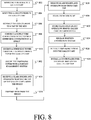
- the embodiments herein provide a method for portable beer dispensing by mounting a beer keg 130 in a galley cart 100, step 802, and mounting a CO2 cylinder 134 in the galley cart 100, step 804.
- the CO2 cylinder 134 is connected to a tap 158 on the keg 130 with a regulator and pressure gage assembly 150, step 806.
- a supply tube connection 162 from the tap 158 is connected to a dispensing tube connection 162 on a spigot 140, step 808.
- a dispensing tower 138 having the spigot 140 is extended from a top 108 of the galley cart 100, step 810, and a position engagement system secures the dispensing tower 138 in the extended position, step 812.
- a glass holder and overflow sump 142 is received on the top 108 of the galley cart 100 under the spigot 140, step 814. Beer is then dispensed, step 816. Upon completion of desired dispensing of beer, the glass holder and overflow sump 142 is removed from the top 108 of the galley cart 100, step 818, and may be emptied, step 820, and stored in the interior cavity 120 of the galley cart 100, step 822. The position engagement system is released, step 824 and the dispensing tower 138 is retracted into the galley cart 100, step 826. A cover plate 182 may be installed to cover a spigot slot 178 on the galley cart top 108, step 828.
Landscapes
- Devices For Dispensing Beverages (AREA)
- Handcart (AREA)
- Filling Or Discharging Of Gas Storage Vessels (AREA)
Abstract
Description
- Embodiments of the disclosure relate generally to the galley cart systems for transportation vehicles and more particularly to a galley cart holding a beverage keg and carbonation cylinder and having a retractable dispensing tower.
- Galley carts employed for food service in transportation vehicles such as aircraft and trains. The galley carts may be insulated to maintain contents at a desired cooler temperature. Beer is typically served from galley carts in aircraft and trains in bottled or canned form. Patrons often prefer draft beer.
- Exemplary embodiments provide a galley cart carbonated beer dispensing system having a housing defining a cavity. A door is coupled to the housing and configured to be moved between a closed position and an open position. A keg is received in the cavity and a carbonation cylinder is received in the cavity and connected to the keg. A spigot is supported on a dispensing tower extending from a top of the housing and connected to the keg. The dispensing tower is retractable into the cavity.
- The embodiments provide a method for dispensing beer by mounting a beer keg a carbon dioxide (CO2) cylinder in the galley cart. The CO2 cylinder is connected to a tap on the keg and a supply tube connection is connected from the tap to a dispensing connection on a spigot. A dispensing tower carrying the spigot is extended from a top of the galley cart and secured with a position engagement system in the extended position. Beer is then dispensed from the spigot.
- The features, functions, and advantages that have been discussed can be achieved independently in various embodiments of the present invention or may be combined in yet other embodiments further details of which can be seen with reference to the following description and drawings.
-
FIG. 1 is a perspective view of an example a galley cart in which the described embodiments may be employed; -
FIG. 2 is a cutaway perspective view of the galley cart ofFIG. 1 with a portion of one side removed to show placement of internal components with the dispensing tower in the extended position; -
FIG. 3 is a detailed perspective view of the dispensing tower retraction and engagement system with the dispensing tower sectioned to reveal connection details; -
FIG. 4 is a perspective view of the dispensing tower in the retracted position and the glass support and overflow sump in the stored position; -
FIG. 5 is a detailed cutaway perspective view of the dispensing tower retraction and engagement system in the retracted position; -
FIG. 6 is a perspective view of the dispensing tower in the retracted position and the cover plate installed; -
FIG. 7A is a detailed perspective view of an alternative embodiment of the dispensing tower; -
FIG. 7B is a detailed perspective view of a second alternative embodiment of the dispensing tower; and, -
FIG. 8 is a flow chart of a beer dispensing method enabled by the disclosed embodiments. - The embodiments described herein provide a storage and dispensing system for a carbonated beverage, such as draft beer, that may be used in conjunction with standard galley carts. More specifically, the embodiments described herein provide a galley cart for use in a transportation vehicle that includes capability for dispensing draft beer while retaining a desired form factor for storage and operation in aircraft or other transportation vehicle galleys. An insulated half-size galley cart houses up to a sixth barrel beer keg (a.k.a., a 5.16 gallon (20 liter) beer keg) and CO2 cylinder for carbonation and employs a dispensing tower with a beer spigot connected to a keg tap, with the dispensing tower retractable into an interior cavity of the galley cart.
- Referring to the drawings,
FIG. 1 is a perspective view of agalley cart 100 which may be employed in the embodiments disclosed herein. In one aspect of this embodiment, thegalley cart 100 includes ahousing 102. In the illustrated embodiment, thehousing 102 has afirst side 104, asecond side 106, atop 108, and abottom 110. Thegalley cart 100 further includes afirst door 112 positioned on one end of thehousing 102, and, for certain embodiments, a second door (seen in subsequent figures) is positioned on an opposite end of thecase 102. Each of thedoors 112 can further include one ormore hinges 114 and alatch 116. Thehinges 114 pivotally attach thedoors 112 to thehousing 102. Thelatch 116 can be configured to releasably engagecorresponding receivers 118 attached to thehousing 102 when thedoors 112 are in closed positions as illustrated inFIG. 1 . Thegalley cart 100 may employ insulation in thehousing 102 to maintain a desired temperature for internal components in the cart. Dry ice or other preconditioned cooling blocks may be employed for cooling. - By disengaging the
latch 116 from thecorresponding receiver 118, thedoors 112 can be opened outwardly providing access to aninterior cavity 120 of thehousing 102 as shown inFIG. 2 . Positioning thedoors 112 at respective ends of thehousing 102 allows flight attendants or service personnel to conveniently access components within thehousing 102 from either end of thegalley cart 100. In other embodiments, the second door can be omitted if desired. Wheels orcasters 124 allow the galley cart to be easily maneuvered within the service areas and aisles of the aircraft. - As seen in
FIG. 2 , an industry standard sixth barrel beer keg 130 (beer industry standard 5.16 gallon keg) is restrained in amounting ring 132 mounted on thebottom 110 of thecart housing 102. A carbonation cylinder such as pressurizedgaseous CO2 cylinder 134, a standard 20 cubic foot (566.3 liter) high pressure cylinder in an exemplary embodiment, is restrained in asecond mounting ring 136. Straps or clamps may be employed alternatively or in addition to the mounting rings to restrain the keg and cylinder within the housing. The sizing of thesixth barrel keg 130 andCO2 cylinder 134 allow accommodation of those elements in an insulated half-size galley cart 100 having exterior dimensions of 12 inches (") x 40" x 16" (30.5 centimeters (cm) x 101.6 cm x 40.5 cm). - A
dispensing tower 138 having aspigot 140 extends upward from thetop 108 of thehousing 102 and a glass support andoverflow sump 142 is received insupports 144 on thetop 108 adjacent thetower 138 to support a glass for filing from thespigot 140 and to catch any overflow from the glass during filing. For the embodiment shown, the glass support andoverflow sump 142 is a self-containedtray 146 and a mesh orscreen top 148 which may be easily removed and inverted to drain any accumulated overflow. In alternative embodiments a drain from the sump to a larger container in the cart or overboard for connection to a supplement drain (or both) may be employed. -
FIG. 3 shows the internal connections between thekeg 130,CO2 cylinder 134 andspigot 140. A regulator andpressure gage assembly 150 is attached to asupply valve 152 on theCO2 cylinder 134. Anoutlet tube connection 154 on the regulator andpressure gage assembly 150 provides CO2 to aninlet tube connection 156 on akeg tap 158 throughline 160 to pressurize thekeg 130. Asupply tube connection 162 on thekeg tap 158 provides beer throughline 164 to a dispensingtube connection 166 attached to thespigot 140.Lines - The dispensing
tower 138 is retractable into thecart housing 102. Thedispensing tower 138 extends from asupport element 168 which is telescopically engaged in acylindrical receiver 172. A position engagement system employsradial engagement stubs 170 extending from thesupport element 168 received invertical slots 174 in thecylindrical receiver 172 for vertical translation and connectinghorizontal detents 176 substantially at atop 177 of the vertical slots allowing rotation of thesupport element 168 to engage the detents to fix the dispensing tower in an extended position seen inFIGs. 1 ,2 and3 . Opposite rotation of thesupport element 168 from thedetents 176 to align theengagement stubs 170 with thevertical slots 174 allows retraction of the dispensing tower into thecart housing 102 as seen inFIGs. 4 and5 . Aslot 178 extending fromreceiver 172 in thetop 108 of thehousing 102 receives thespigot 140 to allow complete retraction for the embodiment shown. - The
dispensing tower 138 is rigidly attached to thesupport element 168 for the embodiment shown and rotates with thesupport element 168. In alternative embodiments, thesupport element 168 and dispensingtower 138 may be engaged in a slip fit arrangement to allow separate rotation of thesupport element 168 for engagement and disengagement from thedetents 176. The glass support andoverflow sump 142 when engaged on the top 108 of thehousing 102 covers theslot 178. The glass support andoverflow sump 142 is removable from the top 108 and may be stored on a shelf orlateral supports 180 in theinterior cavity 120 of thehousing 102 as seen inFIG. 5 and acover plate 182 installed over theslot 178 as seen inFIG. 6 to reduce overall height of thecart 100 for stowing. While shown as extending above the top 108, thesupports 144 may be recessed in the top with a relieved cavity to receive or partially receive the glass support andoverflow sump 142 and cover plate in alternative embodiments (as seen inFIG. 7 ). - As seen in
FIG. 7A , asplit clamp 184 may be employed as a first alternative position engagement system to engage thesupport element 168 of the dispensingtower 138 by compressing slottedsegments 186 in acollar 188 of thecylindrical receiver 172. In other alternative embodiments, the position engagement system may employ removable pins or depressible buttons in the dispensingtower 138 to engage mating features in thecollar 188 of thecylindrical receiver 172. While disclosed in the first embodiment as cylindrical in shape the dispensing tower and support 168' and receiver 172' may be rectangular, as seen inFIG. 7B (dispensing tower 138') or of other geometric form. Additionally while shown as a single segment, the dispensing tower 138' may employmultiple telescoping segments 138", also seen inFIG. 7B , withdepressible buttons 190 received in detent holes 192. - As shown in
FIG. 8 , the embodiments herein provide a method for portable beer dispensing by mounting abeer keg 130 in agalley cart 100,step 802, and mounting aCO2 cylinder 134 in thegalley cart 100,step 804. TheCO2 cylinder 134 is connected to atap 158 on thekeg 130 with a regulator andpressure gage assembly 150,step 806. Asupply tube connection 162 from thetap 158 is connected to a dispensingtube connection 162 on aspigot 140,step 808. A dispensingtower 138 having thespigot 140 is extended from a top 108 of thegalley cart 100,step 810, and a position engagement system secures the dispensingtower 138 in the extended position, step 812. A glass holder andoverflow sump 142 is received on the top 108 of thegalley cart 100 under thespigot 140,step 814. Beer is then dispensed,step 816. Upon completion of desired dispensing of beer, the glass holder andoverflow sump 142 is removed from the top 108 of thegalley cart 100,step 818, and may be emptied,step 820, and stored in theinterior cavity 120 of thegalley cart 100,step 822. The position engagement system is released,step 824 and the dispensingtower 138 is retracted into thegalley cart 100,step 826. Acover plate 182 may be installed to cover aspigot slot 178 on thegalley cart top 108,step 828. - Further, the disclosure comprises embodiments according to the following clauses:
- Clause 1. A galley cart carbonated beverage dispensing system comprising: a housing defining a cavity; a first mounting ring configured to support a beverage keg in the cavity; a second mounting ring configured to support a carbonation cylinder in the cavity, wherein the carbonation cylinder is configured to be connected to the beverage keg; and, a spigot supported on a dispensing tower extending from a top of the housing and configured to be connected to the beverage keg, said dispensing tower retractable into the cavity.
- Clause 2. The galley cart carbonated beverage dispensing system as defined in Clause 1 further comprising a door coupled to the housing, the door configured to be moved between a closed position and an open position.
- Clause 3. The galley cart carbonated beverage dispensing system as defined in Clause 2 further comprising a second door coupled to the housing.
- Clause 4. The galley cart carbonated beverage dispensing system as defined in any one of Clauses 1 to 3 wherein the dispensing tower extends from a support element telescopically engaged in a receiver and further comprising a position engagement system adapted to fix the support element in the receiver at an extended position of the dispensing tower and releasable for vertical translation of the support element in the receiver positioning the dispensing tower in a retracted position.
- Clause 5. The galley cart carbonated beverage dispensing system as defined in Clause 4 wherein the receiver is cylindrical and the position engagement system comprises stubs extending from the support element and received in vertical slots in the receiver, said support element rotatable to engage the stubs in detents proximate a top of the vertical slots.
- Clause 6. The galley cart carbonated beverage dispensing system as defined in Clause 4 wherein the receiver is cylindrical and the position engagement system comprises a split clamp compressing slotted segments in a collar on the receiver to engage the support element.
- Clause 7. The galley cart carbonated beverage dispensing system as defined in Clause 4 wherein the receiver and support element are rectangular, the position engagement system comprising depressible buttons received in detents.
- Clause 8. The galley cart carbonated beverage dispensing system as defined in any one of Clauses 4 to 7 wherein the dispensing tower employs telescoping segments.
- Clause 9. The galley cart carbonated beverage dispensing system as defined in Clause 8 wherein the position engagement system comprising depressible buttons received in detents.
- Clause 10. A galley cart carbonated beverage dispensing system comprising: a housing defining a cavity; a keg received in the cavity; a carbonation cylinder received in the cavity and connected to the keg; and a spigot supported on a dispensing tower extending from a top of the housing and connected to the keg, said dispensing tower retractable into the cavity.
- Clause 11. The galley cart carbonated beverage dispensing system as defined in Clause 10 further comprising a mounting ring on a bottom of the housing receiving the keg.
- Clause 12. The galley cart carbonated beverage dispensing system as defined in Clause 10 or 11 further comprising a second mounting ring on the bottom of the housing receiving the carbonation cylinder.
- Clause 13. The galley cart carbonated beverage dispensing system as defined in any one of Clauses 10 to 12 further comprising a door coupled to the housing, the door configured to be moved between a closed position and an open position.
- Clause 14. The galley cart carbonated beverage dispensing system as defined in Clause 13 further comprising a second door coupled to the housing.
- Clause 15. The galley cart carbonated beverage dispensing system as defined in any one of Clauses 10 to 14 wherein the dispensing tower extends from a support element telescopically engaged in a receiver and further comprising a position engagement system adapted to fix the support element in the receiver at an extended position of the dispensing tower and releasable for vertical translation of the support element in the receiver positioning the dispensing tower in a retracted position.
- Clause 16. The galley cart carbonated beverage dispensing system as defined in Clause 15 wherein the receiver is cylindrical and the position engagement system comprises stubs extending from the support element and received in vertical slots in the receiver, said support element rotatable to engage the stubs in detents proximate a top of the vertical slots.
- Clause 17. The galley cart carbonated beverage dispensing system as defined in Clause 15 wherein the receiver is cylindrical and the position engagement system comprises a split clamp compressing slotted segments in a collar on the receiver to engage the support element.
- Clause 18. The galley cart carbonated beverage dispensing system as defined in Clause 15 wherein the receiver and support element are rectangular, the position engagement system comprising depressible buttons received in detents.
- Clause 19. The galley cart carbonated beverage dispensing system as defined in any one of Clauses 15 to 18 wherein the dispensing tower employs telescoping segments.
- Clause 20. The galley cart carbonated beverage dispensing system as defined in Clause 19 wherein the position engagement system comprising depressible buttons received in detents.
- Clause 21. A method for dispensing a carbonated beverage, the method comprising: mounting a beverage keg in a galley cart; mounting a CO2 cylinder in the galley cart; connecting the CO2 cylinder to a tap on the keg; connecting a supply tube connection from the tap to a dispensing connection on a spigot; extending a dispensing tower carrying the spigot from a top of the galley cart; and securing the dispensing tower with a position engagement system in the extended position.
- Clause 22. The method as defined in Clause 21 further comprising dispensing the beverage from the spigot.
- Clause 23. The method as defined in Clause 22 further comprising: upon completion of desired dispensing of the beverage, releasing the position engagement system; and retracting the dispensing tower into the galley cart.
- Clause 24. The method as defined in any one of Clauses 21 to 23 further comprising receiving a glass holder and overflow sump on the top of the galley cart under the spigot.
- Clause 25. The method as defined in Clause 24 further comprising removing the glass holder and overflow sump from the top of the galley cart and emptying the overflow sump.
- Clause 26. The method as defined in Clause 25 further comprising storing the glass holder and overflow sump in the interior cavity of the galley cart.
- Clause 27. The method as defined in Clause 25 or 26 further comprising installing a cover plate to cover a spigot slot on the galley cart top.
- Having now described various embodiments in detail as required by the patent statutes, those skilled in the art will recognize modifications and substitutions to the specific embodiments disclosed herein. Such modifications are within the scope and intent of the present disclosure as defined in the following claims.
Claims (15)
- A galley cart carbonated beverage dispensing system comprising:a housing (102) defining a cavity (120);a first mounting ring (132) configured to support a beverage keg (130) in the cavity;a second mounting ring (136) configured to support a carbonation cylinder (134) in the cavity, wherein the carbonation cylinder is configured to be connected to the beverage keg; and,a spigot (140) supported on a dispensing tower (138) extending from a top (108) of the housing and configured to be connected to the beverage keg, said dispensing tower retractable into the cavity.
- The galley cart carbonated beverage dispensing system as defined in claim 1 further comprising a door (112) coupled to the housing (102), the door configured to be moved between a closed position and an open position.
- The galley cart carbonated beverage dispensing system as defined in claim 2 further comprising a second door (113) coupled to the housing (102).
- The galley cart carbonated beverage dispensing system as defined in any one of claims 1 to 3 wherein the dispensing tower (138) extends from a support element (168) telescopically engaged in a receiver (172) and further comprising a position engagement system adapted to fix the support element in the receiver at an extended position of the dispensing tower and releasable for vertical translation of the support element in the receiver positioning the dispensing tower in a retracted position.
- The galley cart carbonated beverage dispensing system as defined in claim 4 wherein the receiver (172) is cylindrical and the position engagement system comprises one of:stubs (170) extending from the support element (168) and received in vertical slots (174) in the receiver, said support element rotatable to engage the stubs in detents (176) proximate a top (177) of the vertical slots; ora split clamp (184) compressing slotted segments (186) in a collar (188) on the receiver to engage the support element (168).
- The galley cart carbonated beverage dispensing system as defined in claim 4 wherein the receiver (172) and support element (168) are rectangular, the position engagement system comprising depressible buttons (190) received in detents (192).
- The galley cart carbonated beverage dispensing system as defined in any one of claims 4 to 6 wherein the dispensing tower (138') employs telescoping segments (138").
- The galley cart carbonated beverage dispensing system as defined in claim 7 wherein the position engagement system comprising depressible buttons (190) received in detents (192).
- A method for dispensing a carbonated beverage, the method comprising:mounting (802) a beverage keg (130) in a galley cart (100);mounting (804) a CO2 cylinder (134) in the galley cart;connecting (806) the CO2 cylinder to a tap (158) on the keg;connecting (808) a supply tube connection (162) from the tap to a dispensing connection (162) on a spigot (140);extending (810) a dispensing tower (138) carrying the spigot from a top (108) of the galley cart; andsecuring (812) the dispensing tower with a position engagement system in the extended position.
- The method as defined in claim 9 further comprising dispensing (816) the beverage from the spigot (140).
- The method as defined in claim 10 further comprising:upon completion of desired dispensing of the beverage, releasing (824) the position engagement system; andretracting (826) the dispensing tower (138) into the galley cart (100).
- The method as defined in any one of claims 9 to 11 further comprising receiving (814) a glass holder and overflow sump (142) on the top (108) of the galley cart (100) under the spigot (140).
- The method as defined in claim 12 further comprising removing (818) the glass holder and overflow sump (142) from the top (108) of the galley cart (100) and emptying (820) the overflow sump.
- The method as defined in claim 13 further comprising storing (822) the glass holder and overflow sump (142) in the interior cavity (120) of the galley cart (100).
- The method as defined in claim 13 or 14 further comprising installing (828) a cover plate (182) to cover a spigot slot (178) on the top (108) of the galley cart (100).
Applications Claiming Priority (1)
| Application Number | Priority Date | Filing Date | Title |
|---|---|---|---|
| US15/186,871 US10053355B2 (en) | 2016-06-20 | 2016-06-20 | Adaptable insulated galley cart carbonated beverage delivery system |
Publications (2)
| Publication Number | Publication Date |
|---|---|
| EP3260412A1 true EP3260412A1 (en) | 2017-12-27 |
| EP3260412B1 EP3260412B1 (en) | 2019-12-18 |
Family
ID=58261581
Family Applications (1)
| Application Number | Title | Priority Date | Filing Date |
|---|---|---|---|
| EP17159575.4A Active EP3260412B1 (en) | 2016-06-20 | 2017-03-07 | Adaptable insulated galley cart carbonated beverage delivery system |
Country Status (5)
| Country | Link |
|---|---|
| US (2) | US10053355B2 (en) |
| EP (1) | EP3260412B1 (en) |
| JP (1) | JP6980422B2 (en) |
| BR (1) | BR102017007412B1 (en) |
| CA (1) | CA2960206C (en) |
Cited By (2)
| Publication number | Priority date | Publication date | Assignee | Title |
|---|---|---|---|---|
| EP3819258A1 (en) * | 2019-11-11 | 2021-05-12 | Micro Matic A/S | A beverage dispensing system |
| WO2021089755A1 (en) * | 2019-11-08 | 2021-05-14 | Micro Matic A/S | A beverage dispensing system |
Families Citing this family (7)
| Publication number | Priority date | Publication date | Assignee | Title |
|---|---|---|---|---|
| US10065848B2 (en) * | 2015-10-08 | 2018-09-04 | Dee Volin | Unique self-pressurizing, self-cooling beverage system, having impact-and-vibration-absorbing systems, anti-shaking anti-rolling clamping system, root-beer-float system, beverage-dispensing system, and multi-height spigot system |
| US11352138B2 (en) | 2018-10-08 | 2022-06-07 | The Boeing Company | Galley cart with selectable meal preparation |
| EP3891093A4 (en) * | 2018-12-05 | 2022-08-31 | Pepsico Inc | NON-ELECTRIC BEVERAGE DISPENSER AND FOUNTAIN SYSTEMS |
| USD903967S1 (en) * | 2019-03-29 | 2020-12-01 | Essentium Inc | Filament cart |
| US11472691B2 (en) * | 2020-02-21 | 2022-10-18 | Timothy Ohara | Assembly for providing a passageway for a beverage line connected between a beverage vessel contained in a cabinet, and a beverage tap secured to a tabletop accessory |
| US11662131B1 (en) * | 2021-08-25 | 2023-05-30 | Thomas Black | Assembly and method for cooling and dispensing draft beer and other beverages |
| US12349790B2 (en) * | 2023-11-08 | 2025-07-08 | David Cameron | Hazardous material storage shed system |
Citations (5)
| Publication number | Priority date | Publication date | Assignee | Title |
|---|---|---|---|---|
| US2083776A (en) * | 1934-05-02 | 1937-06-15 | Otis L Smith | Liquid dispensing apparatus |
| US3180529A (en) * | 1962-01-26 | 1965-04-27 | Herman L Buffington | Portable refrigerated bar |
| US3232489A (en) * | 1966-02-01 | Portable cooler cabinet construction | ||
| US4350267A (en) * | 1979-12-26 | 1982-09-21 | Nelson Richard E | Portable modular beverage dispenser |
| US6648187B1 (en) * | 2002-09-13 | 2003-11-18 | Eugene G. Shypkowski | Extendable spout for use with ice and water dispensers |
Family Cites Families (36)
| Publication number | Priority date | Publication date | Assignee | Title |
|---|---|---|---|---|
| US1676108A (en) * | 1927-01-04 | 1928-07-03 | Novak James | Convertible table |
| US2627445A (en) * | 1945-10-24 | 1953-02-03 | Clifford T Lyon | Equipment for the preparation and storage of food |
| US2845780A (en) * | 1956-01-17 | 1958-08-05 | Swartzbaugh Mfg Company | Food service cart |
| US2861857A (en) * | 1957-04-01 | 1958-11-25 | Lee Theodore | Combined table and cabinet |
| US3275393A (en) * | 1959-10-13 | 1966-09-27 | United Service Equipment Co In | Hot and cold food service cart |
| US3065037A (en) * | 1959-12-29 | 1962-11-20 | Chester R Chapman | Extensible bar |
| US3232491A (en) * | 1963-05-22 | 1966-02-01 | Reynolds Metals Co | Container for a keg or the like |
| US3229859A (en) * | 1964-10-23 | 1966-01-18 | Frederick M Conroy | Extension tools |
| US3327902A (en) * | 1965-10-22 | 1967-06-27 | Alterwitz Melvin | Chilled beverage dispensing system |
| US3650591A (en) * | 1970-04-08 | 1972-03-21 | Ernest B Longmire Sr | Elevator shelf unit |
| US3677173A (en) * | 1970-08-03 | 1972-07-18 | William A Fogle Jr | Steamer and soda-dispensing system |
| JPS4852115U (en) * | 1971-10-14 | 1973-07-06 | ||
| US3932009A (en) * | 1972-01-11 | 1976-01-13 | Hansrudolf Zollinger | Table |
| US3940019A (en) * | 1974-09-30 | 1976-02-24 | Leisure Products Corporation | Automatic mixed drink dispensing apparatus |
| US3974658A (en) * | 1975-08-20 | 1976-08-17 | Starrett Richard F | Contact refrigeration unit |
| US4161234A (en) * | 1978-03-13 | 1979-07-17 | Clyde Munn | Serving cart |
| JPS6029988U (en) * | 1983-08-05 | 1985-02-28 | 日産自動車株式会社 | Metal pipe fitting structure |
| US4581902A (en) * | 1984-08-20 | 1986-04-15 | Starck Jane G | Combination storage container and table |
| NL8503067A (en) * | 1985-11-08 | 1987-06-01 | Heineken Technische Beheer Bv | BEER TAPER. |
| JPH02125907A (en) * | 1989-09-22 | 1990-05-14 | Honda Motor Co Ltd | exhaust pipe fittings |
| US5626353A (en) * | 1994-06-09 | 1997-05-06 | Campbell; Craig | Mobile cart including beverage chilling and dispensing apparatus |
| JP2926566B1 (en) * | 1998-02-17 | 1999-07-28 | 日本電気移動通信株式会社 | Telescopic steel column for outdoor loudspeaker installation of municipal emergency radio system |
| JP2001225896A (en) * | 2000-02-14 | 2001-08-21 | Sapporo Breweries Ltd | Beverage server |
| US7246727B2 (en) * | 2000-06-09 | 2007-07-24 | Heineken Technical Services B.V. | Container for drink provided with a chamber containing a flexible dispensing line |
| US6481238B1 (en) * | 2001-08-13 | 2002-11-19 | Cold-Sell Systems, L.L.C. | Keg server |
| JP2006077895A (en) * | 2004-09-09 | 2006-03-23 | Calsonic Kansei Corp | Pipe connection part structure |
| US9067614B2 (en) * | 2005-04-25 | 2015-06-30 | M & C Innovations, Llc | Travel cooler with transitionable U-shaped handle |
| JP2008054896A (en) * | 2006-08-31 | 2008-03-13 | Techno Care:Kk | Ratchet type extending and contracting walking stick |
| US7861892B1 (en) * | 2008-03-04 | 2011-01-04 | White Richard W | Portable draft bar |
| US8672200B2 (en) * | 2009-01-09 | 2014-03-18 | Matthew J. O'Hare | Tailgating system |
| US7909148B1 (en) * | 2009-09-29 | 2011-03-22 | Miller Larry D | Combination food cooler and table assembly |
| DE102010014392B4 (en) * | 2010-04-08 | 2011-12-29 | Air-Eltec Luftfahrtelektrik Gmbh | Serving trolley for the preparation and dispensing of drinks |
| US8936260B2 (en) * | 2012-07-20 | 2015-01-20 | B/E Aerospace, Inc. | Meal cart for an aircraft galley |
| US9193461B2 (en) | 2013-05-09 | 2015-11-24 | The Boeing Company | Insulated galley cart and method of using frozen refrigerant bricks to maximize storage volume and equalize temperature distribution |
| US9809238B2 (en) * | 2015-01-28 | 2017-11-07 | Pik Six LLC | Compact portable cooling container and keg dispenser |
| US10065848B2 (en) * | 2015-10-08 | 2018-09-04 | Dee Volin | Unique self-pressurizing, self-cooling beverage system, having impact-and-vibration-absorbing systems, anti-shaking anti-rolling clamping system, root-beer-float system, beverage-dispensing system, and multi-height spigot system |
-
2016
- 2016-06-20 US US15/186,871 patent/US10053355B2/en active Active
-
2017
- 2017-03-07 EP EP17159575.4A patent/EP3260412B1/en active Active
- 2017-03-07 CA CA2960206A patent/CA2960206C/en active Active
- 2017-04-10 BR BR102017007412-9A patent/BR102017007412B1/en active IP Right Grant
- 2017-06-16 JP JP2017118934A patent/JP6980422B2/en active Active
-
2018
- 2018-07-09 US US16/029,842 patent/US10689238B2/en active Active
Patent Citations (5)
| Publication number | Priority date | Publication date | Assignee | Title |
|---|---|---|---|---|
| US3232489A (en) * | 1966-02-01 | Portable cooler cabinet construction | ||
| US2083776A (en) * | 1934-05-02 | 1937-06-15 | Otis L Smith | Liquid dispensing apparatus |
| US3180529A (en) * | 1962-01-26 | 1965-04-27 | Herman L Buffington | Portable refrigerated bar |
| US4350267A (en) * | 1979-12-26 | 1982-09-21 | Nelson Richard E | Portable modular beverage dispenser |
| US6648187B1 (en) * | 2002-09-13 | 2003-11-18 | Eugene G. Shypkowski | Extendable spout for use with ice and water dispensers |
Cited By (4)
| Publication number | Priority date | Publication date | Assignee | Title |
|---|---|---|---|---|
| WO2021089755A1 (en) * | 2019-11-08 | 2021-05-14 | Micro Matic A/S | A beverage dispensing system |
| CN114929616A (en) * | 2019-11-08 | 2022-08-19 | 微马蒂奇股份公司 | Beverage dispensing system |
| CN114929616B (en) * | 2019-11-08 | 2025-12-09 | 微马蒂奇股份公司 | Beverage dispensing system |
| EP3819258A1 (en) * | 2019-11-11 | 2021-05-12 | Micro Matic A/S | A beverage dispensing system |
Also Published As
| Publication number | Publication date |
|---|---|
| US10053355B2 (en) | 2018-08-21 |
| JP6980422B2 (en) | 2021-12-15 |
| JP2018024474A (en) | 2018-02-15 |
| US20170362072A1 (en) | 2017-12-21 |
| BR102017007412B1 (en) | 2022-03-08 |
| CA2960206C (en) | 2021-05-11 |
| CA2960206A1 (en) | 2017-12-20 |
| BR102017007412A2 (en) | 2018-01-02 |
| US10689238B2 (en) | 2020-06-23 |
| EP3260412B1 (en) | 2019-12-18 |
| US20180319647A1 (en) | 2018-11-08 |
Similar Documents
| Publication | Publication Date | Title |
|---|---|---|
| US10689238B2 (en) | Adaptable insulated galley cart carbonated beverage delivery system | |
| US7044335B2 (en) | Self-contained beverage dispensing apparatus | |
| US9499386B2 (en) | Wine storage and dispensing apparatus | |
| US8360277B2 (en) | Assembly for dispensing beverage | |
| US9981746B2 (en) | Dispensing architecture for a hybrid fountain beverage consumable cart and galley dispensing system | |
| US20150097001A1 (en) | Mobile beverage cart | |
| CN104540737B (en) | Dining carts for aircraft galleys | |
| US20080093384A1 (en) | Self-contained beverage dispenser | |
| US20110073615A1 (en) | Product storage and handling system for beverage dispenser | |
| US20140069954A1 (en) | Chilled Beverage Dispenser | |
| EP2504272A1 (en) | A method for installing a collapsible beverage container in a beverage dispensing system | |
| US20130056495A1 (en) | Beer Dispensing Device and System | |
| US20190382042A1 (en) | Catering truck on aeroplane | |
| US20160347597A1 (en) | Beverage transport and dispensing cart | |
| EP3374313B1 (en) | A beverage container handling unit | |
| US11680734B2 (en) | Portable insulated thermo-electric cooler and dispenser | |
| EP4424595A1 (en) | Aircraft beverage system | |
| US20120228311A1 (en) | Disposable cask with disposable tap | |
| US10867462B1 (en) | Self-vending beverage distribution station | |
| WO2010073049A1 (en) | Portable beverage dispenser | |
| EP2141089A1 (en) | Moveable aerosol can collector and foam applicator | |
| CN119239949A (en) | A handbrake type semi-self-service airline dining car |
Legal Events
| Date | Code | Title | Description |
|---|---|---|---|
| PUAI | Public reference made under article 153(3) epc to a published international application that has entered the european phase |
Free format text: ORIGINAL CODE: 0009012 |
|
| STAA | Information on the status of an ep patent application or granted ep patent |
Free format text: STATUS: REQUEST FOR EXAMINATION WAS MADE |
|
| 17P | Request for examination filed |
Effective date: 20170307 |
|
| AK | Designated contracting states |
Kind code of ref document: A1 Designated state(s): AL AT BE BG CH CY CZ DE DK EE ES FI FR GB GR HR HU IE IS IT LI LT LU LV MC MK MT NL NO PL PT RO RS SE SI SK SM TR |
|
| AX | Request for extension of the european patent |
Extension state: BA ME |
|
| STAA | Information on the status of an ep patent application or granted ep patent |
Free format text: STATUS: EXAMINATION IS IN PROGRESS |
|
| 17Q | First examination report despatched |
Effective date: 20180920 |
|
| GRAP | Despatch of communication of intention to grant a patent |
Free format text: ORIGINAL CODE: EPIDOSNIGR1 |
|
| STAA | Information on the status of an ep patent application or granted ep patent |
Free format text: STATUS: GRANT OF PATENT IS INTENDED |
|
| RIC1 | Information provided on ipc code assigned before grant |
Ipc: B67D 1/08 20060101ALI20190305BHEP Ipc: B67D 1/06 20060101ALI20190305BHEP Ipc: A47B 81/00 20060101ALI20190305BHEP Ipc: B67D 1/00 20060101ALI20190305BHEP Ipc: B64D 11/00 20060101ALI20190305BHEP Ipc: B67D 1/04 20060101AFI20190305BHEP Ipc: B61D 37/00 20060101ALI20190305BHEP |
|
| INTG | Intention to grant announced |
Effective date: 20190328 |
|
| GRAJ | Information related to disapproval of communication of intention to grant by the applicant or resumption of examination proceedings by the epo deleted |
Free format text: ORIGINAL CODE: EPIDOSDIGR1 |
|
| STAA | Information on the status of an ep patent application or granted ep patent |
Free format text: STATUS: EXAMINATION IS IN PROGRESS |
|
| INTC | Intention to grant announced (deleted) | ||
| GRAP | Despatch of communication of intention to grant a patent |
Free format text: ORIGINAL CODE: EPIDOSNIGR1 |
|
| STAA | Information on the status of an ep patent application or granted ep patent |
Free format text: STATUS: GRANT OF PATENT IS INTENDED |
|
| INTG | Intention to grant announced |
Effective date: 20190711 |
|
| GRAS | Grant fee paid |
Free format text: ORIGINAL CODE: EPIDOSNIGR3 |
|
| GRAA | (expected) grant |
Free format text: ORIGINAL CODE: 0009210 |
|
| STAA | Information on the status of an ep patent application or granted ep patent |
Free format text: STATUS: THE PATENT HAS BEEN GRANTED |
|
| AK | Designated contracting states |
Kind code of ref document: B1 Designated state(s): AL AT BE BG CH CY CZ DE DK EE ES FI FR GB GR HR HU IE IS IT LI LT LU LV MC MK MT NL NO PL PT RO RS SE SI SK SM TR |
|
| REG | Reference to a national code |
Ref country code: CH Ref legal event code: EP |
|
| REG | Reference to a national code |
Ref country code: IE Ref legal event code: FG4D |
|
| REG | Reference to a national code |
Ref country code: DE Ref legal event code: R096 Ref document number: 602017009721 Country of ref document: DE |
|
| REG | Reference to a national code |
Ref country code: AT Ref legal event code: REF Ref document number: 1214400 Country of ref document: AT Kind code of ref document: T Effective date: 20200115 |
|
| REG | Reference to a national code |
Ref country code: NL Ref legal event code: MP Effective date: 20191218 |
|
| PG25 | Lapsed in a contracting state [announced via postgrant information from national office to epo] |
Ref country code: FI Free format text: LAPSE BECAUSE OF FAILURE TO SUBMIT A TRANSLATION OF THE DESCRIPTION OR TO PAY THE FEE WITHIN THE PRESCRIBED TIME-LIMIT Effective date: 20191218 Ref country code: NO Free format text: LAPSE BECAUSE OF FAILURE TO SUBMIT A TRANSLATION OF THE DESCRIPTION OR TO PAY THE FEE WITHIN THE PRESCRIBED TIME-LIMIT Effective date: 20200318 Ref country code: BG Free format text: LAPSE BECAUSE OF FAILURE TO SUBMIT A TRANSLATION OF THE DESCRIPTION OR TO PAY THE FEE WITHIN THE PRESCRIBED TIME-LIMIT Effective date: 20200318 Ref country code: GR Free format text: LAPSE BECAUSE OF FAILURE TO SUBMIT A TRANSLATION OF THE DESCRIPTION OR TO PAY THE FEE WITHIN THE PRESCRIBED TIME-LIMIT Effective date: 20200319 Ref country code: LV Free format text: LAPSE BECAUSE OF FAILURE TO SUBMIT A TRANSLATION OF THE DESCRIPTION OR TO PAY THE FEE WITHIN THE PRESCRIBED TIME-LIMIT Effective date: 20191218 Ref country code: SE Free format text: LAPSE BECAUSE OF FAILURE TO SUBMIT A TRANSLATION OF THE DESCRIPTION OR TO PAY THE FEE WITHIN THE PRESCRIBED TIME-LIMIT Effective date: 20191218 Ref country code: LT Free format text: LAPSE BECAUSE OF FAILURE TO SUBMIT A TRANSLATION OF THE DESCRIPTION OR TO PAY THE FEE WITHIN THE PRESCRIBED TIME-LIMIT Effective date: 20191218 |
|
| REG | Reference to a national code |
Ref country code: LT Ref legal event code: MG4D |
|
| PG25 | Lapsed in a contracting state [announced via postgrant information from national office to epo] |
Ref country code: HR Free format text: LAPSE BECAUSE OF FAILURE TO SUBMIT A TRANSLATION OF THE DESCRIPTION OR TO PAY THE FEE WITHIN THE PRESCRIBED TIME-LIMIT Effective date: 20191218 Ref country code: RS Free format text: LAPSE BECAUSE OF FAILURE TO SUBMIT A TRANSLATION OF THE DESCRIPTION OR TO PAY THE FEE WITHIN THE PRESCRIBED TIME-LIMIT Effective date: 20191218 |
|
| PG25 | Lapsed in a contracting state [announced via postgrant information from national office to epo] |
Ref country code: AL Free format text: LAPSE BECAUSE OF FAILURE TO SUBMIT A TRANSLATION OF THE DESCRIPTION OR TO PAY THE FEE WITHIN THE PRESCRIBED TIME-LIMIT Effective date: 20191218 |
|
| PG25 | Lapsed in a contracting state [announced via postgrant information from national office to epo] |
Ref country code: CZ Free format text: LAPSE BECAUSE OF FAILURE TO SUBMIT A TRANSLATION OF THE DESCRIPTION OR TO PAY THE FEE WITHIN THE PRESCRIBED TIME-LIMIT Effective date: 20191218 Ref country code: NL Free format text: LAPSE BECAUSE OF FAILURE TO SUBMIT A TRANSLATION OF THE DESCRIPTION OR TO PAY THE FEE WITHIN THE PRESCRIBED TIME-LIMIT Effective date: 20191218 Ref country code: PT Free format text: LAPSE BECAUSE OF FAILURE TO SUBMIT A TRANSLATION OF THE DESCRIPTION OR TO PAY THE FEE WITHIN THE PRESCRIBED TIME-LIMIT Effective date: 20200513 Ref country code: EE Free format text: LAPSE BECAUSE OF FAILURE TO SUBMIT A TRANSLATION OF THE DESCRIPTION OR TO PAY THE FEE WITHIN THE PRESCRIBED TIME-LIMIT Effective date: 20191218 Ref country code: RO Free format text: LAPSE BECAUSE OF FAILURE TO SUBMIT A TRANSLATION OF THE DESCRIPTION OR TO PAY THE FEE WITHIN THE PRESCRIBED TIME-LIMIT Effective date: 20191218 |
|
| PG25 | Lapsed in a contracting state [announced via postgrant information from national office to epo] |
Ref country code: SM Free format text: LAPSE BECAUSE OF FAILURE TO SUBMIT A TRANSLATION OF THE DESCRIPTION OR TO PAY THE FEE WITHIN THE PRESCRIBED TIME-LIMIT Effective date: 20191218 Ref country code: SK Free format text: LAPSE BECAUSE OF FAILURE TO SUBMIT A TRANSLATION OF THE DESCRIPTION OR TO PAY THE FEE WITHIN THE PRESCRIBED TIME-LIMIT Effective date: 20191218 Ref country code: IS Free format text: LAPSE BECAUSE OF FAILURE TO SUBMIT A TRANSLATION OF THE DESCRIPTION OR TO PAY THE FEE WITHIN THE PRESCRIBED TIME-LIMIT Effective date: 20200418 |
|
| REG | Reference to a national code |
Ref country code: DE Ref legal event code: R097 Ref document number: 602017009721 Country of ref document: DE |
|
| REG | Reference to a national code |
Ref country code: AT Ref legal event code: MK05 Ref document number: 1214400 Country of ref document: AT Kind code of ref document: T Effective date: 20191218 |
|
| PLBE | No opposition filed within time limit |
Free format text: ORIGINAL CODE: 0009261 |
|
| STAA | Information on the status of an ep patent application or granted ep patent |
Free format text: STATUS: NO OPPOSITION FILED WITHIN TIME LIMIT |
|
| PG25 | Lapsed in a contracting state [announced via postgrant information from national office to epo] |
Ref country code: DK Free format text: LAPSE BECAUSE OF FAILURE TO SUBMIT A TRANSLATION OF THE DESCRIPTION OR TO PAY THE FEE WITHIN THE PRESCRIBED TIME-LIMIT Effective date: 20191218 Ref country code: MC Free format text: LAPSE BECAUSE OF FAILURE TO SUBMIT A TRANSLATION OF THE DESCRIPTION OR TO PAY THE FEE WITHIN THE PRESCRIBED TIME-LIMIT Effective date: 20191218 Ref country code: ES Free format text: LAPSE BECAUSE OF FAILURE TO SUBMIT A TRANSLATION OF THE DESCRIPTION OR TO PAY THE FEE WITHIN THE PRESCRIBED TIME-LIMIT Effective date: 20191218 |
|
| REG | Reference to a national code |
Ref country code: CH Ref legal event code: PL |
|
| 26N | No opposition filed |
Effective date: 20200921 |
|
| PG25 | Lapsed in a contracting state [announced via postgrant information from national office to epo] |
Ref country code: AT Free format text: LAPSE BECAUSE OF FAILURE TO SUBMIT A TRANSLATION OF THE DESCRIPTION OR TO PAY THE FEE WITHIN THE PRESCRIBED TIME-LIMIT Effective date: 20191218 Ref country code: SI Free format text: LAPSE BECAUSE OF FAILURE TO SUBMIT A TRANSLATION OF THE DESCRIPTION OR TO PAY THE FEE WITHIN THE PRESCRIBED TIME-LIMIT Effective date: 20191218 |
|
| REG | Reference to a national code |
Ref country code: BE Ref legal event code: MM Effective date: 20200331 |
|
| PG25 | Lapsed in a contracting state [announced via postgrant information from national office to epo] |
Ref country code: LU Free format text: LAPSE BECAUSE OF NON-PAYMENT OF DUE FEES Effective date: 20200307 |
|
| PG25 | Lapsed in a contracting state [announced via postgrant information from national office to epo] |
Ref country code: LI Free format text: LAPSE BECAUSE OF NON-PAYMENT OF DUE FEES Effective date: 20200331 Ref country code: IT Free format text: LAPSE BECAUSE OF FAILURE TO SUBMIT A TRANSLATION OF THE DESCRIPTION OR TO PAY THE FEE WITHIN THE PRESCRIBED TIME-LIMIT Effective date: 20191218 Ref country code: CH Free format text: LAPSE BECAUSE OF NON-PAYMENT OF DUE FEES Effective date: 20200331 Ref country code: IE Free format text: LAPSE BECAUSE OF NON-PAYMENT OF DUE FEES Effective date: 20200307 |
|
| PG25 | Lapsed in a contracting state [announced via postgrant information from national office to epo] |
Ref country code: BE Free format text: LAPSE BECAUSE OF NON-PAYMENT OF DUE FEES Effective date: 20200331 Ref country code: PL Free format text: LAPSE BECAUSE OF FAILURE TO SUBMIT A TRANSLATION OF THE DESCRIPTION OR TO PAY THE FEE WITHIN THE PRESCRIBED TIME-LIMIT Effective date: 20191218 |
|
| PG25 | Lapsed in a contracting state [announced via postgrant information from national office to epo] |
Ref country code: TR Free format text: LAPSE BECAUSE OF FAILURE TO SUBMIT A TRANSLATION OF THE DESCRIPTION OR TO PAY THE FEE WITHIN THE PRESCRIBED TIME-LIMIT Effective date: 20191218 Ref country code: MT Free format text: LAPSE BECAUSE OF FAILURE TO SUBMIT A TRANSLATION OF THE DESCRIPTION OR TO PAY THE FEE WITHIN THE PRESCRIBED TIME-LIMIT Effective date: 20191218 Ref country code: CY Free format text: LAPSE BECAUSE OF FAILURE TO SUBMIT A TRANSLATION OF THE DESCRIPTION OR TO PAY THE FEE WITHIN THE PRESCRIBED TIME-LIMIT Effective date: 20191218 |
|
| PG25 | Lapsed in a contracting state [announced via postgrant information from national office to epo] |
Ref country code: MK Free format text: LAPSE BECAUSE OF FAILURE TO SUBMIT A TRANSLATION OF THE DESCRIPTION OR TO PAY THE FEE WITHIN THE PRESCRIBED TIME-LIMIT Effective date: 20191218 |
|
| P01 | Opt-out of the competence of the unified patent court (upc) registered |
Effective date: 20230516 |
|
| PGFP | Annual fee paid to national office [announced via postgrant information from national office to epo] |
Ref country code: GB Payment date: 20260327 Year of fee payment: 10 |
|
| PGFP | Annual fee paid to national office [announced via postgrant information from national office to epo] |
Ref country code: DE Payment date: 20260327 Year of fee payment: 10 |
|
| PGFP | Annual fee paid to national office [announced via postgrant information from national office to epo] |
Ref country code: FR Payment date: 20260325 Year of fee payment: 10 |