EP3260219B1 - Mold vibrating device - Google Patents
Mold vibrating device Download PDFInfo
- Publication number
- EP3260219B1 EP3260219B1 EP16752354.7A EP16752354A EP3260219B1 EP 3260219 B1 EP3260219 B1 EP 3260219B1 EP 16752354 A EP16752354 A EP 16752354A EP 3260219 B1 EP3260219 B1 EP 3260219B1
- Authority
- EP
- European Patent Office
- Prior art keywords
- shaft
- mold
- lubricating oil
- ball screw
- nut
- Prior art date
- Legal status (The legal status is an assumption and is not a legal conclusion. Google has not performed a legal analysis and makes no representation as to the accuracy of the status listed.)
- Active
Links
Images



Classifications
-
- B—PERFORMING OPERATIONS; TRANSPORTING
- B22—CASTING; POWDER METALLURGY
- B22D—CASTING OF METALS; CASTING OF OTHER SUBSTANCES BY THE SAME PROCESSES OR DEVICES
- B22D11/00—Continuous casting of metals, i.e. casting in indefinite lengths
- B22D11/04—Continuous casting of metals, i.e. casting in indefinite lengths into open-ended moulds
- B22D11/053—Means for oscillating the moulds
-
- F—MECHANICAL ENGINEERING; LIGHTING; HEATING; WEAPONS; BLASTING
- F16—ENGINEERING ELEMENTS AND UNITS; GENERAL MEASURES FOR PRODUCING AND MAINTAINING EFFECTIVE FUNCTIONING OF MACHINES OR INSTALLATIONS; THERMAL INSULATION IN GENERAL
- F16H—GEARING
- F16H25/00—Gearings comprising primarily only cams, cam-followers and screw-and-nut mechanisms
- F16H25/18—Gearings comprising primarily only cams, cam-followers and screw-and-nut mechanisms for conveying or interconverting oscillating or reciprocating motions
- F16H25/20—Screw mechanisms
- F16H25/22—Screw mechanisms with balls, rollers, or similar members between the co-operating parts; Elements essential to the use of such members
-
- F—MECHANICAL ENGINEERING; LIGHTING; HEATING; WEAPONS; BLASTING
- F16—ENGINEERING ELEMENTS AND UNITS; GENERAL MEASURES FOR PRODUCING AND MAINTAINING EFFECTIVE FUNCTIONING OF MACHINES OR INSTALLATIONS; THERMAL INSULATION IN GENERAL
- F16H—GEARING
- F16H25/00—Gearings comprising primarily only cams, cam-followers and screw-and-nut mechanisms
- F16H25/18—Gearings comprising primarily only cams, cam-followers and screw-and-nut mechanisms for conveying or interconverting oscillating or reciprocating motions
- F16H25/20—Screw mechanisms
- F16H25/22—Screw mechanisms with balls, rollers, or similar members between the co-operating parts; Elements essential to the use of such members
- F16H25/2204—Screw mechanisms with balls, rollers, or similar members between the co-operating parts; Elements essential to the use of such members with balls
-
- F—MECHANICAL ENGINEERING; LIGHTING; HEATING; WEAPONS; BLASTING
- F16—ENGINEERING ELEMENTS AND UNITS; GENERAL MEASURES FOR PRODUCING AND MAINTAINING EFFECTIVE FUNCTIONING OF MACHINES OR INSTALLATIONS; THERMAL INSULATION IN GENERAL
- F16H—GEARING
- F16H25/00—Gearings comprising primarily only cams, cam-followers and screw-and-nut mechanisms
- F16H25/18—Gearings comprising primarily only cams, cam-followers and screw-and-nut mechanisms for conveying or interconverting oscillating or reciprocating motions
- F16H25/20—Screw mechanisms
- F16H25/24—Elements essential to such mechanisms, e.g. screws, nuts
-
- F—MECHANICAL ENGINEERING; LIGHTING; HEATING; WEAPONS; BLASTING
- F16—ENGINEERING ELEMENTS AND UNITS; GENERAL MEASURES FOR PRODUCING AND MAINTAINING EFFECTIVE FUNCTIONING OF MACHINES OR INSTALLATIONS; THERMAL INSULATION IN GENERAL
- F16H—GEARING
- F16H57/00—General details of gearing
- F16H57/02—Gearboxes; Mounting gearing therein
- F16H57/029—Gearboxes; Mounting gearing therein characterised by means for sealing the gearboxes, e.g. to improve airtightness
-
- F—MECHANICAL ENGINEERING; LIGHTING; HEATING; WEAPONS; BLASTING
- F16—ENGINEERING ELEMENTS AND UNITS; GENERAL MEASURES FOR PRODUCING AND MAINTAINING EFFECTIVE FUNCTIONING OF MACHINES OR INSTALLATIONS; THERMAL INSULATION IN GENERAL
- F16H—GEARING
- F16H57/00—General details of gearing
- F16H57/04—Features relating to lubrication or cooling or heating
- F16H57/048—Type of gearings to be lubricated, cooled or heated
- F16H57/0497—Screw mechanisms
-
- H—ELECTRICITY
- H02—GENERATION; CONVERSION OR DISTRIBUTION OF ELECTRIC POWER
- H02K—DYNAMO-ELECTRIC MACHINES
- H02K7/00—Arrangements for handling mechanical energy structurally associated with dynamo-electric machines, e.g. structural association with mechanical driving motors or auxiliary dynamo-electric machines
- H02K7/06—Means for converting reciprocating motion into rotary motion or vice versa
-
- H—ELECTRICITY
- H02—GENERATION; CONVERSION OR DISTRIBUTION OF ELECTRIC POWER
- H02K—DYNAMO-ELECTRIC MACHINES
- H02K7/00—Arrangements for handling mechanical energy structurally associated with dynamo-electric machines, e.g. structural association with mechanical driving motors or auxiliary dynamo-electric machines
- H02K7/10—Structural association with clutches, brakes, gears, pulleys or mechanical starters
-
- H—ELECTRICITY
- H02—GENERATION; CONVERSION OR DISTRIBUTION OF ELECTRIC POWER
- H02K—DYNAMO-ELECTRIC MACHINES
- H02K7/00—Arrangements for handling mechanical energy structurally associated with dynamo-electric machines, e.g. structural association with mechanical driving motors or auxiliary dynamo-electric machines
- H02K7/10—Structural association with clutches, brakes, gears, pulleys or mechanical starters
- H02K7/1004—Structural association with clutches, brakes, gears, pulleys or mechanical starters with pulleys
-
- F—MECHANICAL ENGINEERING; LIGHTING; HEATING; WEAPONS; BLASTING
- F16—ENGINEERING ELEMENTS AND UNITS; GENERAL MEASURES FOR PRODUCING AND MAINTAINING EFFECTIVE FUNCTIONING OF MACHINES OR INSTALLATIONS; THERMAL INSULATION IN GENERAL
- F16H—GEARING
- F16H25/00—Gearings comprising primarily only cams, cam-followers and screw-and-nut mechanisms
- F16H25/18—Gearings comprising primarily only cams, cam-followers and screw-and-nut mechanisms for conveying or interconverting oscillating or reciprocating motions
- F16H25/20—Screw mechanisms
- F16H2025/2031—Actuator casings
-
- F—MECHANICAL ENGINEERING; LIGHTING; HEATING; WEAPONS; BLASTING
- F16—ENGINEERING ELEMENTS AND UNITS; GENERAL MEASURES FOR PRODUCING AND MAINTAINING EFFECTIVE FUNCTIONING OF MACHINES OR INSTALLATIONS; THERMAL INSULATION IN GENERAL
- F16H—GEARING
- F16H25/00—Gearings comprising primarily only cams, cam-followers and screw-and-nut mechanisms
- F16H25/18—Gearings comprising primarily only cams, cam-followers and screw-and-nut mechanisms for conveying or interconverting oscillating or reciprocating motions
- F16H25/20—Screw mechanisms
- F16H2025/2043—Screw mechanisms driving an oscillating lever, e.g. lever with perpendicular pivoting axis
-
- F—MECHANICAL ENGINEERING; LIGHTING; HEATING; WEAPONS; BLASTING
- F16—ENGINEERING ELEMENTS AND UNITS; GENERAL MEASURES FOR PRODUCING AND MAINTAINING EFFECTIVE FUNCTIONING OF MACHINES OR INSTALLATIONS; THERMAL INSULATION IN GENERAL
- F16H—GEARING
- F16H25/00—Gearings comprising primarily only cams, cam-followers and screw-and-nut mechanisms
- F16H25/18—Gearings comprising primarily only cams, cam-followers and screw-and-nut mechanisms for conveying or interconverting oscillating or reciprocating motions
- F16H25/20—Screw mechanisms
- F16H2025/2062—Arrangements for driving the actuator
- F16H2025/2096—Arrangements for driving the actuator using endless flexible members
Definitions
- the present invention relates to a mold oscillator for oscillating a mold to reduce friction between the mold and a surface of a cast piece in a continuous casting machine for continuously casting steel or the like.
- molten steel is poured from a tundish into a rectangular tube-shaped mold and the molten steel is cooled through contact with the mold, a cast piece, in which unsolidified steel is present at the center portion thereof, is continuously drawn downward, and molten steel is continuously poured into the mold.
- the cast piece drawn downward out of the mold is water cooled by water spray.
- the cast piece is cut into pieces of predetermined length and sent to a downstream process, that is, rolling.
- molten steel is brought into contact with the inner side surface of the mold, so that the molten steel is cooled and a solidified shell is formed.
- the mold is oscillated in the vertical direction (Patent Document 1). This prevents the cast piece from adhering to the inner side surface of the mold, so that it is possible to smoothly draw the cast piece out of the bottom of the mold.
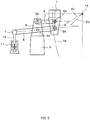
- FIG. 8 is a schematic diagram showing an eccentric cam-type mold oscillator.
- an arm support portion 3 is mounted on a partition wall 6.
- One end portion of a sub-arm 4 and a midpoint portion of a main arm 5 are respectively supported in a swingable manner by horizontal pivot shafts 3a and 3b provided in the arm support portion 3.
- a mold 1 is supported on an oscillation table 2 and oscillated together with the oscillation table 2.
- the other end portion of the sub-arm 4 and one end portion of the main arm 5 are respectively connected to horizontal pivot shafts 2a and 2b of the oscillation table 2 in a swingable manner.
- the main arm 5 and the sub-arm 4 constitute a parallel link, so that the four points, the pivot shafts 3a, 3b, 2b and 2a, operate in relation to one another with distances therebetween being fixed.
- the distance between the pivot shafts 2a and 2b, the distance between the pivot shafts 3a and 3b, the distance between the pivot shafts 3a and 2a, and the distance between the pivot shafts 3b and 2b are set so that extensions of line segments 2c and 2d cross each other at a swing arm center 1a, the line segment 2c connecting between the pivot shaft 3a and the pivot shaft 2a, the line segment 2d connecting between the pivot shaft 3b and the pivot shaft 2b.
- a motor 10 is mounted on an installation floor with the pivot shaft being horizontally positioned.
- the rotary shaft of the motor 10 is provided with an eccentric cam 9.
- the eccentric cam 9 and a pivot shaft 7 at the other end of the main arm 5 are connected via a link 8. Accordingly, rotation of the motor 10 causes rotation of the eccentric cam 9, which in turn causes vertical movement of the link 8 via the eccentric cam 9.
- the vertical movement of the link 8 causes the main arm 5 to swing, which in turn causes the sub-arm 4 to swing. In this way, the mold 1 is oscillated in the vertical direction.
- FIG. 9 is a schematic diagram showing a hydraulic servo-type mold oscillator.
- a hydraulic servo-type mold oscillator In this hydraulic servo-type mold oscillator, a hydraulic servo cylinder 11 is installed in place of the eccentric cam.
- an upper end of a piston 12 In the hydraulic servo cylinder 11, an upper end of a piston 12 is rotatably connected to a pivot shaft 7, so that the other end portion (pivot shaft 7) of a main arm 5 is caused to reciprocate in the vertical direction by the piston 12 driven by the hydraulic servo cylinder 11.
- FIG. 10 is a schematic diagram showing an electrically driven servo-type mold oscillator.
- an electrically driven servo actuator 20 is installed in place of the eccentric cam shown in FIG. 8 .
- FIG. 11 is a schematic diagram showing the electrically driven servo actuator 20.
- a base 21 is mounted on an installation floor.
- a servo motor 22 and a cylinder tube 33 are installed on the base 21.
- the servo motor 22 is installed so that a rotary shaft 23 is positioned in the base 21 with the axial direction of the rotary shaft 23 being directed downward in the vertical direction.
- the rotary shaft 23 is provided with a pulley 24.
- a threaded shaft 29 of a ball screw is rotatably installed via angular bearings 55 with the axial direction of the threaded shaft 29 being directed in the vertical direction, and a lower part of the threaded shaft 29 is positioned in the base 21.
- a pulley 25 is fixed to a lower end portion of the threaded shaft 29.
- a belt 26 is looped between the pulley 24 and the pulley 25. Accordingly, forward and reverse rotation of the motor 22 causes forward and reverse rotation of the threaded shaft 29 via the belt 26. Accordingly, in this embodiment, the pulleys 24 and 25, and the belt 26 function as the power transmitting mechanism.
- a nut-side shaft 31 is fixed to a ball nut 30 coaxially with the threaded shaft 29 that is positioned with the central axis thereof being directed in the vertical direction.
- the ball nut 30 is screw-fitted on the threaded shaft 29 with balls interposed therebetween. Forward and reverse rotation of the threaded shaft 29 causes the ball nut 30 to move in the vertical direction.
- the nut-side shaft 31 is fixed to the upper end of the ball nut 30 with the axial direction of the nut-side shaft 31 being directed in the vertical direction.
- the nut-side shaft 31 is supported by ball splines 34 so as to be able to move in the vertical direction.
- the upper end of the nut-side shaft 31 protrudes upward from an upper portion of the cylinder tube 33.
- the upper end of the nut-side shaft 31 is connected to the pivot shaft 7 at the other end of the main arm 5.
- the belt 26 transmits rotational driving force produced by forward and reverse rotation of the rotary shaft 23 of the servo motor 22 to the threaded shaft 29 in the cylinder tube 33, which causes forward and reverse rotation of the threaded shaft 29.
- the forward and reverse rotation of the threaded shaft 29 causes the ball nut 30 screw-fitted on the threaded shaft 29 to move in the vertical direction, which in turn causes the nut-side shaft 31 fixed to the upper end of the ball nut 30 to move in the vertical direction.
- the swinging motion of the main arm 5 is followed by swinging motion of a sub-arm 4, which in turn causes a mold 1 to oscillate in the vertical direction.
- Patent Document 1 Japanese Translation of PCT International Application Publication No. H11-506982 ( JP 11-506982 A )
- amplitude of oscillation cannot be changed during casting operation.
- a pattern with time, or waveform, of oscillation of the mold is limited to a sinusoidal wave.
- amplitude of oscillation of the mold can be changed even during casting operation by adjusting timing of control of the pressure for advancing the piston 12 of the hydraulic servo cylinder 11 and the pressure for retracting the piston 12.
- the pattern of the mold oscillation is not limited to a sinusoidal wave and it is possible to set a non-sinusoidal waveform.
- amplitude of oscillation of the mold can be changed even during casting operation.
- the pattern of the mold oscillation can be set to either of a sinusoidal waveform and a non-sinusoidal waveform.
- the hydraulic servo-type mold oscillator requires inspection of filters, hydraulic oil, etc. of the hydraulic servo cylinder 11. Moreover, it is required to control contamination of the hydraulic oil.
- the nut-side shaft 31 is caused to move in the vertical direction by forward and reverse rotation of the servo motor.
- the amplitude required for the purpose of mold oscillation is small, that is, about ⁇ 6 mm for example.
- the rotation angle of the threaded shaft 29 for swinging operation is small and moreover, long-time continuous operation is required, which means that the threaded shaft 29 and the ball nut 30 are required to operate under severe conditions.
- ordinary grease is used to lubricate the threaded shaft 29 and the ball nut 30.
- the threaded shaft 29 is repeatedly rotated forward and backward within a small oscillatory rotation angle and therefore, there is a possibility that breakdown of oil film occurs in the case of grease lubrication.
- the present invention has been made in consideration of such a problem and an object of the present invention is to provide an easy-to-maintain, electrically driven servo-type mold oscillator, with which it is possible to increase service life.
- a mold oscillator according to the present invention is a mold oscillator for oscillating a mold of a continuous casting machine, characterized by including:
- This mold oscillator may further include: a bearing supporting the first shaft so that the first shaft can rotate about a central axis thereof; and a bearing retainer, in which a channel for communicating the outlet port with a space between an inner race and an outer race of the bearing is formed, the bearing retainer being fixed under the bearing at a position corresponding to a midpoint portion of the first shaft in a longitudinal direction thereof, wherein a seal contacting the first shaft is included in the bearing retainer so as to prevent the lubricating oil from leaking downward.
- the mold oscillator further includes:
- a configuration may be adopted, in which a sealing member for sealing a gap between the casing and the second shaft is detachably fitted.
- the mold oscillator according to the present invention may further include an arm mechanism, having an arm extending in a lateral direction, for oscillating the mold by moving the mold in the vertical direction through swinging movement of the arm, wherein a fulcrum is provided at a midpoint portion of the arm, one end of the arm is connected to the second shaft, and the other end of the arm is connected to the mold.
- an arm mechanism having an arm extending in a lateral direction, for oscillating the mold by moving the mold in the vertical direction through swinging movement of the arm, wherein a fulcrum is provided at a midpoint portion of the arm, one end of the arm is connected to the second shaft, and the other end of the arm is connected to the mold.
- the ball nut of the ball screw and part of the threaded shaft of the ball screw, on which part the ball nut is engaged with the threaded shaft are submerged in a lubricating oil to lubricate the ball screw with an oil bath, and therefore, it is possible to sufficiently lubricate moving parts in the casing. Accordingly, it is possible to significantly elongate life of the moving parts included in the actuator of the mold oscillator.
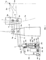
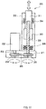
- FIG. 1 is a schematic diagram showing a concept of an electrically driven actuator 120 of a mold oscillator according to the embodiment of the present invention.
- the electrically driven actuator 120 of the mold oscillator shown in FIG. 1 is obtained by further installing a lubricating oil tank 41 under a base 21 and a pump 40 for circulating a lubricating oil stored in the lubricating oil tank 41 through a cylinder tube 33, which functions as the casing of the present invention, in addition to the electrically driven actuator 20 shown in FIG. 11 .
- the lubricating oil sent under pressure from the pump 40 is passed through a filter (not shown), supplied to an upper portion of the cylinder tube 33 via a supply pipe 43, and collected from a lower portion of the cylinder tube 33 into the tank 41 through a collection pipe 42, whereby the lubricating oil is circulated for lubrication of a threaded shaft 29 and a ball nut 30.
- the threaded shaft 29 and the ball nut 30 are submerged in the lubricating oil bath, so that the threaded shaft 29 and the ball nut 30, which are oscillated within a small oscillatory rotation angle and operated for a long time, are lubricated without breakdown of oil film.
- the lubricating oil is collected in the tank 41, so that it is possible to easily determine the degree of degradation of the lubricating oil, which makes it possible to determine the timing of performing an overhaul of the actuator 120 of the mold oscillator.
- the supply device includes the supply pipe 43, the pump 40, and the filter (not shown).
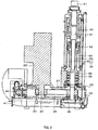
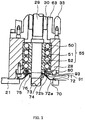
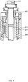
- FIG. 2 is a front sectional view showing the electrically driven actuator 120, and FIGS. 3 and 4 are partially enlarged views thereof.
- FIG. 5 is a side sectional view of the same.
- the base 21 is mounted on an installation floor.
- the circular cylinder tube 33 the central axis of which is directed in the vertical direction, is fixed in a standing position on the base 21, a bearing support portion 28 is provided under the cylinder tube 33, and angular bearings 55 are fitted into the bearing support portion 28.
- the threaded shaft 29 is rotatably supported by the angular bearings 55 with the central axis of the threaded shaft 29 being directed in the vertical direction.
- an outer race 51 and an inner race 52 are fixed, the outer race 51 supporting balls 50 on the outer side, the inner race 52 supporting the balls 50 on the inner side and being in contact with an outer circumferential surface of the threaded shaft 29.
- the balls 50 are held between the inner race 52 and the outer race 51 so as not to fall out. In this way, the balls 50 rotate in a state where the balls 50 are held between the inner race 52 and the outer race 51, so that the threaded shaft 29 is supported so as to be rotatable about the central axis thereof.
- the ball screw is positioned so that the central axis thereof is directed in the vertical direction as in the case of this embodiment, it is possible to secure high stability and durability.
- the ball nut 30 is disposed in this cylinder tube 33 and is screw-fitted on the threaded shaft 29 with the balls interposed therebetween.
- a nut-side shaft 31 fixed to the ball nut 30 coaxially with the threaded shaft 29 is also disposed.
- a lower end portion of the nut-side shaft 31 is fixed to an upper end portion of the ball nut 30.
- the threaded shaft 29 functions as the first shaft of the present invention and the nut-side shaft 31 functions as the second shaft.
- Ball splines 34 are fixed to an inner surface of the cylinder tube 33 at a position corresponding to the nut-side shaft 31.
- the nut-side shaft 31 is supported by the ball splines 34 so as to be able to reciprocate in the vertical direction and so as not to be rotatable. Since the nut-side shaft 31 is supported by the ball splines 34 so as not to be rotatable, the nut-side shaft 31 cannot rotate about the central axis thereof. Accordingly, forward and reverse rotation (oscillatory rotation) of the threaded shaft 29 about the central axis thereof causes the ball nut 30, which is screw-fitted on the threaded shaft 29 with the balls interposed therebetween, to reciprocate in the vertical direction within a range corresponding to the oscillatory rotation angle.
- the nut-side shaft 31 is supported by the ball splines 34 so as to be able to move in the vertical direction and so as not to be rotatable and therefore, the nut-side shaft 31 fixed to the ball nut 30 moves in the vertical direction within the range equal to that of the ball nut 30.
- a cylindrical stopper 63 is disposed so as to surround the threaded shaft 29.
- a sealing member 65 for sealing a gap is detachably fitted between the cylinder tube 33 and the nut-side shaft 31.
- the nut-side shaft 31 continuously oscillates in the vertical direction and therefore, the sealing member of this portion wears severely.
- the sealing member 65 is detachably fitted in this way, it it possible to avoid a situation where the entire cylinder tube 33 must be replaced because of wear of the portion contacting the nut-side shaft 31 (second shaft).
- An upper end of the nut-side shaft 31 protrudes upward from the upper portion of the cylinder tube 33.
- the upper end of the nut-side shaft 31 is connected to the mold side.
- the upper end of the nut-side shaft 31 is provided with a connection portion 61, which is rotatably connected to a pivot shaft 7 of a main arm 5.
- the main arm 5 swings and oscillates the mold.
- a motor 22 is installed on the base 21 in parallel with the cylinder tube 33.
- a rotary shaft 23 of the motor 22 is inserted into the base 21 with the rotation axis of the rotary shaft 23 being directed in the vertical direction.
- the rotary shaft 23 is provided with a pulley 24.
- the part of the threaded shaft 29 that is inserted in the base 21 is provided with a pulley 25.
- a belt 26 is looped between the pulleys 24 and 25, so that oscillatory rotation of the rotary shaft 23 of the motor 22 is transmitted to the threaded shaft 29 via the belt 26.
- the lubricating oil tank 41 is provided below the base 21 and the lubricating oil in the lubricating oil tank 41 is supplied to an inlet port 90 (see FIG. 5 ) provided in the upper portion of the cylinder tube 33 via the supply pipe 43 (see FIG. 1 ) by the small pump 40 provided above the lubricating oil tank 41.
- the lubricating oil supplied into the cylinder tube 33 is collected into the lubricating oil tank 41 from an outlet port 91 provided in the bearing retainer 80 in the lower portion of the casing through the collection pipe 42 (see FIGS. 1 and 2 ).
- the position, at which the inlet port is provided, is not particularly limited as long as the inlet port is provided above the outlet port.
- the inlet port be provided above an element for supporting the second shaft (the nut-side shaft 31 in this embodiment) so as to be movable in the vertical direction and so as not to be rotatable, such as ball splines, as in the case of this embodiment.
- the lubricating oil for lubricating the supporting element is also supplied by the supply device through the filter, so that it is possible to perform lubrication with the use of the lubricating oil, from which contaminants have been removed.
- a bearing retainer 80 is fixed at the bottom surface of the angular bearings 55.
- FIG. 6 is a front sectional view of the bearing retainer 80.
- FIG. 7 is a bottom view of the bearing retainer 80.
- the bearing retainer 80 has a circular ring shape and has a three stepped structure, including an inner hole 84 at the upper surface that has the smallest radius, a middle hole 82 that is formed below the inner hole 84, and a lower hole 83 that is formed below the middle hole 82.
- an upper end 85 that has a radius smaller than that of the outermost edge of the bearing retainer 80 is formed as a step.
- Part of the upper surface of the bearing retainer 80 is slightly lowered to form a hollow 81 in the radially inner side of the upper end 85.
- the upper end 85 has a diameter the same as that of the outer edge of the bearings 55.
- the retainer 80 is fixed to the bottom surface of the bearing support portion 28 by screws with the upper end 85 being in contact with the bearing 55.
- a seal 74 is fitted into the middle hole 82 of the retainer 80.
- a metal ring 73 is disposed so as to be fitted onto the threaded shaft 29 between the seal 74 and the threaded shaft 29.
- a cylindrical fixing member 76 is fixed so as to be fitted onto the threaded shaft 29, and a parasol shaped member, which has a cone shape widening downward and has a horizontal ring shaped portion at the upper end, is sandwiched between the metal ring 73 and the fixing member 76, forming a rotary parasol portion 71.
- the seal 74 is fixed to the retainer 80 so as not to be separated from the retainer 80 by fixing a circular ring shaped retaining plate 75 to the bottom surface of the retainer 80 by screws.
- An oval counterbored hole portion 85a is formed on the upper surface side of the retainer 80 in a portion extending from the hollow 81 to the radially outer side of the upper end 85, and a channel 87 passing through the retainer 80 in a plate thickness direction is formed in a bottom portion of the counterbored hole portion 85a in a radially outer side.
- the lubricating oil flows out of the outlet port 91 through the channel 87 in the retainer 80 and is introduced into the lubricating oil tank 41 via the collection pipe 42.
- the cylinder tube 33, the bearing support portion 28, and the bearing retainer 80 function as the casing of the present invention.
- the rotary parasol portion 71 is formed by fitting the parasol shaped member, which has the cone shape widening downward and has the horizontal ring shaped portion at the upper end, onto the threaded shaft 29 and sandwiching the horizontal ring shaped portion between the metal ring 73 and the fixing member 76 to fix the parasol shaped member to the threaded shaft 29.
- a stationary parasol portion 72 is formed by fixing a horizontal portion 72a of a parasol shaped member to an upper surface of the base 21, which parasol shaped member has a cone shaped portion 72b widening downward at an angle the same as that of the cone shaped portion of the rotary parasol portion 71 and has the horizontal portion 72a extending horizontally outward from the lower end of the cone shaped portion 72b.
- the horizontal portion 72a of the parasol shaped member forming the stationary parasol portion 72 is fixed to a peripheral portion around the opening 70.
- the rotary parasol portion 71 that rotates with the threaded shaft 29 and the stationary parasol portion 72 that is fixed to the base 21 are disposed so that the rotary parasol portion 71 is positioned on the upper side of the stationary parasol portion 72 and the cone shaped portions of these parasol portions at least partially overlap each other in the radial direction around the entire circumference.
- a drain outlet 93 for discharging, into the outside, the lubricating oil received on the upper surface of the stationary parasol portion 72 is provided in the bearing support portion 28.
- the lubricating oil flows on the cone shaped portion of the rotary parasol portion 71 and the cone shaped portion of the stationary parasol portion 72 to be introduced onto the horizontal portion 72a of the stationary parasol portion 72, and is then discharged into the outside from the drain outlet 93. Accordingly, even when the lubricating oil leaks downward from the inner edge of the retainer 80, the lubricating oil is prevented from leaking to the area under the stationary parasol portion 72 to reach the pulley 25 or the belt 26. In this embodiment, the lubricating oil discharged from the drain outlet 93 into the outside is not collected into the lubricating oil tank, that is, discarded into the outside.
- operation is performed in a state where the threaded shaft 29 and the ball nut 30 are submerged in the lubricating oil, so that wear is significantly reduced.
- This makes it possible to increase life of the actuator of the mold oscillator.
- providing the rotary parasol portion 71 and the stationary parasol portion 72 makes it possible to obtain more secure sealing against leakage of the lubricating oil to prevent the lubricating oil from entering the inside of the base 21, so that it is possible to prevent the lubricating oil from adhering to the pulleys 24 and 25 and the belt 26 in the base 21 to hamper operation thereof and to prevent deterioration of the belt.
- the nut-side shaft may be positioned on the lower side as the first shaft. That is, the ball screw unit may be disposed in an inverted position relative to the position in the case of the above embodiments.
- the outlet port of the present invention is provided below the bearings in the lower portion of the casing in the above embodiments
- the outlet port may be provided above the bearings in the lower portion of the casing as long as the upper or lower end of the bearings is liquid-tightly sealed.
- the outlet port is provided below the bearings and the lubricating oil is passed through the space between the inner races and the outer races of the bearings and is then collected as in the case of the above embodiments, it is possible to prevent contaminants from remaining in the bearings.
Landscapes
- Engineering & Computer Science (AREA)
- General Engineering & Computer Science (AREA)
- Mechanical Engineering (AREA)
- Power Engineering (AREA)
- Transmission Devices (AREA)
- Continuous Casting (AREA)
- Connection Of Motors, Electrical Generators, Mechanical Devices, And The Like (AREA)
Description
- The present invention relates to a mold oscillator for oscillating a mold to reduce friction between the mold and a surface of a cast piece in a continuous casting machine for continuously casting steel or the like.
- In a continuous casting machine for continuously casting steel, molten steel is poured from a tundish into a rectangular tube-shaped mold and the molten steel is cooled through contact with the mold, a cast piece, in which unsolidified steel is present at the center portion thereof, is continuously drawn downward, and molten steel is continuously poured into the mold. The cast piece drawn downward out of the mold is water cooled by water spray. Finally, after completely solidified, the cast piece is cut into pieces of predetermined length and sent to a downstream process, that is, rolling.
- In the mold, molten steel is brought into contact with the inner side surface of the mold, so that the molten steel is cooled and a solidified shell is formed. In order to prevent the solidified shell from adhering to the inner side surface of the mold, the mold is oscillated in the vertical direction (Patent Document 1). This prevents the cast piece from adhering to the inner side surface of the mold, so that it is possible to smoothly draw the cast piece out of the bottom of the mold.
-
FIG. 8 is a schematic diagram showing an eccentric cam-type mold oscillator. As shown inFIG. 8 , anarm support portion 3 is mounted on apartition wall 6. One end portion of asub-arm 4 and a midpoint portion of amain arm 5 are respectively supported in a swingable manner byhorizontal pivot shafts arm support portion 3. Amold 1 is supported on an oscillation table 2 and oscillated together with the oscillation table 2. The other end portion of thesub-arm 4 and one end portion of themain arm 5 are respectively connected tohorizontal pivot shafts main arm 5 and thesub-arm 4 constitute a parallel link, so that the four points, thepivot shafts pivot shafts pivot shafts pivot shafts pivot shafts line segments swing arm center 1a, theline segment 2c connecting between thepivot shaft 3a and thepivot shaft 2a, theline segment 2d connecting between thepivot shaft 3b and thepivot shaft 2b. Accordingly, when the parallel link (themain arm 5 and the sub-arm 4) swings, themold 1 is oscillated (swings) in the vertical direction about theswing arm center 1a along an arc with a certain curvature radius. - A
motor 10 is mounted on an installation floor with the pivot shaft being horizontally positioned. The rotary shaft of themotor 10 is provided with aneccentric cam 9. Theeccentric cam 9 and apivot shaft 7 at the other end of themain arm 5 are connected via alink 8. Accordingly, rotation of themotor 10 causes rotation of theeccentric cam 9, which in turn causes vertical movement of thelink 8 via theeccentric cam 9. The vertical movement of thelink 8 causes themain arm 5 to swing, which in turn causes thesub-arm 4 to swing. In this way, themold 1 is oscillated in the vertical direction. -
FIG. 9 is a schematic diagram showing a hydraulic servo-type mold oscillator. In this hydraulic servo-type mold oscillator, ahydraulic servo cylinder 11 is installed in place of the eccentric cam. In thehydraulic servo cylinder 11, an upper end of apiston 12 is rotatably connected to apivot shaft 7, so that the other end portion (pivot shaft 7) of amain arm 5 is caused to reciprocate in the vertical direction by thepiston 12 driven by thehydraulic servo cylinder 11. -
FIG. 10 is a schematic diagram showing an electrically driven servo-type mold oscillator. In this electrically driven servo-type mold oscillator, an electrically drivenservo actuator 20 is installed in place of the eccentric cam shown inFIG. 8 .FIG. 11 is a schematic diagram showing the electrically drivenservo actuator 20. Abase 21 is mounted on an installation floor. Aservo motor 22 and acylinder tube 33 are installed on thebase 21. Theservo motor 22 is installed so that arotary shaft 23 is positioned in thebase 21 with the axial direction of therotary shaft 23 being directed downward in the vertical direction. Therotary shaft 23 is provided with apulley 24. A threadedshaft 29 of a ball screw is rotatably installed viaangular bearings 55 with the axial direction of the threadedshaft 29 being directed in the vertical direction, and a lower part of the threadedshaft 29 is positioned in thebase 21. Apulley 25 is fixed to a lower end portion of the threadedshaft 29. Abelt 26 is looped between thepulley 24 and thepulley 25. Accordingly, forward and reverse rotation of themotor 22 causes forward and reverse rotation of the threadedshaft 29 via thebelt 26. Accordingly, in this embodiment, thepulleys belt 26 function as the power transmitting mechanism. - In the
cylinder tube 33, a nut-side shaft 31 is fixed to aball nut 30 coaxially with the threadedshaft 29 that is positioned with the central axis thereof being directed in the vertical direction. Theball nut 30 is screw-fitted on the threadedshaft 29 with balls interposed therebetween. Forward and reverse rotation of the threadedshaft 29 causes theball nut 30 to move in the vertical direction. The nut-side shaft 31 is fixed to the upper end of theball nut 30 with the axial direction of the nut-side shaft 31 being directed in the vertical direction. The nut-side shaft 31 is supported byball splines 34 so as to be able to move in the vertical direction. The upper end of the nut-side shaft 31 protrudes upward from an upper portion of thecylinder tube 33. The upper end of the nut-side shaft 31 is connected to thepivot shaft 7 at the other end of themain arm 5. - In the electrically driven servo-type mold oscillator, the
belt 26 transmits rotational driving force produced by forward and reverse rotation of therotary shaft 23 of theservo motor 22 to the threadedshaft 29 in thecylinder tube 33, which causes forward and reverse rotation of the threadedshaft 29. The forward and reverse rotation of the threadedshaft 29 causes theball nut 30 screw-fitted on the threadedshaft 29 to move in the vertical direction, which in turn causes the nut-side shaft 31 fixed to the upper end of theball nut 30 to move in the vertical direction. In this way, amain arm 5, to which an upper end portion of the nut-side shaft 31 is connected via apivot shaft 7, swings about apivot shaft 3b. The swinging motion of themain arm 5 is followed by swinging motion of asub-arm 4, which in turn causes amold 1 to oscillate in the vertical direction. - [Patent Document 1] Japanese Translation of
PCT International Application Publication No. H11-506982 JP 11-506982 A - However, in the eccentric cam-type mold oscillator, amplitude of oscillation cannot be changed during casting operation. Moreover, a pattern with time, or waveform, of oscillation of the mold is limited to a sinusoidal wave. In contrast, in the hydraulic servo-type mold oscillator, amplitude of oscillation of the mold can be changed even during casting operation by adjusting timing of control of the pressure for advancing the
piston 12 of thehydraulic servo cylinder 11 and the pressure for retracting thepiston 12. Moreover, the pattern of the mold oscillation is not limited to a sinusoidal wave and it is possible to set a non-sinusoidal waveform. Also in the electrically driven servo-type mold oscillator, amplitude of oscillation of the mold can be changed even during casting operation. Moreover, the pattern of the mold oscillation can be set to either of a sinusoidal waveform and a non-sinusoidal waveform. - However, the hydraulic servo-type mold oscillator requires inspection of filters, hydraulic oil, etc. of the
hydraulic servo cylinder 11. Moreover, it is required to control contamination of the hydraulic oil. - In the case of the electrically driven servo-type mold oscillator, the nut-
side shaft 31 is caused to move in the vertical direction by forward and reverse rotation of the servo motor. In this case, the amplitude required for the purpose of mold oscillation is small, that is, about ±6 mm for example. This means that the amplitude of the vertical movement of thepivot shaft 7 of themain arm 5 is correspondingly small. For this reason, the rotation angle of the threadedshaft 29 for swinging operation is small and moreover, long-time continuous operation is required, which means that the threadedshaft 29 and theball nut 30 are required to operate under severe conditions. Conventionally, ordinary grease is used to lubricate the threadedshaft 29 and theball nut 30. However, the threadedshaft 29 is repeatedly rotated forward and backward within a small oscillatory rotation angle and therefore, there is a possibility that breakdown of oil film occurs in the case of grease lubrication. - The present invention has been made in consideration of such a problem and an object of the present invention is to provide an easy-to-maintain, electrically driven servo-type mold oscillator, with which it is possible to increase service life.
- A mold oscillator according to the present invention is a mold oscillator for oscillating a mold of a continuous casting machine, characterized by including:
- a servo motor;
- a ball screw unit that has a ball screw having a threaded shaft and a ball nut, and a nut-side shaft fixed to the ball nut coaxially with the threaded shaft, wherein the ball screw unit is positioned so that a central axis of the ball screw unit extends in a vertical direction;
- a power transmitting mechanism that transmits rotation of a rotary shaft of the servo motor to a first shaft that is one of the threaded shaft and the nut-side shaft of the ball screw unit that is positioned on a lower side;
- a casing that surrounds at least part of the ball screw, the casing being configured so as to be able to submerge the ball nut of the ball screw and part of the threaded shaft of the ball screw, on which part the ball nut is engaged with the threaded shaft, in a lubricating oil to lubricate the ball screw with an oil bath;
- a lubricating oil tank that stores the lubricating oil;
- a collection pipe for introducing the lubricating oil to the lubricating oil tank, the collection pipe being connected to an outlet port provided in a lower portion of the casing; and
- a supply device for resupplying the lubricating oil in the lubricating oil tank into the casing through an inlet port provided above the outlet port in the casing, wherein
- a second shaft that is the other of the threaded shaft and the nut-side shaft of the ball screw unit is connected to the mold side.
- This mold oscillator may further include: a bearing supporting the first shaft so that the first shaft can rotate about a central axis thereof; and a bearing retainer, in which a channel for communicating the outlet port with a space between an inner race and an outer race of the bearing is formed, the bearing retainer being fixed under the bearing at a position corresponding to a midpoint portion of the first shaft in a longitudinal direction thereof, wherein a seal contacting the first shaft is included in the bearing retainer so as to prevent the lubricating oil from leaking downward.
- In the mold oscillator according to the present invention, a configuration may be adopted, in which
the mold oscillator further includes: - a rotary parasol portion provided on a side surface of the first shaft of the ball screw unit below the bearing retainer and having a parasol shape widening downward, the rotary parasol portion being configured to rotate with the first shaft; and
- a stationary parasol portion fixed under the rotary parasol portion and having a parasol shape widening downward, the stationary parasol portion being disposed so as to at least partially overlap the rotary parasol portion in a radial direction around an entire circumference, wherein
- a drain outlet for discharging, into the outside, the lubricating oil received on the stationary parasol portion is provided in the casing.
- In the mold oscillator according to the present invention, a configuration may be adopted, in which
a sealing member for sealing a gap between the casing and the second shaft is detachably fitted. - The mold oscillator according to the present invention may further include an arm mechanism, having an arm extending in a lateral direction, for oscillating the mold by moving the mold in the vertical direction through swinging movement of the arm, wherein a fulcrum is provided at a midpoint portion of the arm, one end of the arm is connected to the second shaft, and the other end of the arm is connected to the mold.
- According to the present invention, the ball nut of the ball screw and part of the threaded shaft of the ball screw, on which part the ball nut is engaged with the threaded shaft, are submerged in a lubricating oil to lubricate the ball screw with an oil bath, and therefore, it is possible to sufficiently lubricate moving parts in the casing. Accordingly, it is possible to significantly elongate life of the moving parts included in the actuator of the mold oscillator.
-
-
FIG. 1 is a schematic diagram showing an electrically drivenactuator 120 of a mold oscillator according to an embodiment of the present invention. -
FIG. 2 is a front sectional view showing the electrically drivenactuator 120 of the embodiment. -
FIG. 3 is a partially enlarged view of the same. -
FIG. 4 is a partially enlarged view of the same. -
FIG. 5 is a side sectional view of the same. -
FIG. 6 is a front sectional view of a bearingretainer 80. -
FIG. 7 is a bottom view of the bearingretainer 80. -
FIG. 8 is a diagram showing a conventional eccentric cam-type mold oscillator. -
FIG. 9 is a diagram showing a conventional hydraulic servo-type mold oscillator. -
FIG. 10 is a diagram showing a conventional electrically driven servo-type mold oscillator. -
FIG. 11 is a diagram showing an electrically driven actuator of the conventional electrically driven servo-type mold oscillator. - An embodiment of the present invention will be specifically described below with reference to the accompanying drawings.
FIG. 1 is a schematic diagram showing a concept of an electrically drivenactuator 120 of a mold oscillator according to the embodiment of the present invention. The electrically drivenactuator 120 of the mold oscillator shown inFIG. 1 is obtained by further installing a lubricatingoil tank 41 under abase 21 and apump 40 for circulating a lubricating oil stored in the lubricatingoil tank 41 through acylinder tube 33, which functions as the casing of the present invention, in addition to the electrically drivenactuator 20 shown inFIG. 11 . The lubricating oil sent under pressure from thepump 40 is passed through a filter (not shown), supplied to an upper portion of thecylinder tube 33 via asupply pipe 43, and collected from a lower portion of thecylinder tube 33 into thetank 41 through acollection pipe 42, whereby the lubricating oil is circulated for lubrication of a threadedshaft 29 and aball nut 30. In this embodiment, the threadedshaft 29 and theball nut 30 are submerged in the lubricating oil bath, so that the threadedshaft 29 and theball nut 30, which are oscillated within a small oscillatory rotation angle and operated for a long time, are lubricated without breakdown of oil film. Moreover, the lubricating oil is collected in thetank 41, so that it is possible to easily determine the degree of degradation of the lubricating oil, which makes it possible to determine the timing of performing an overhaul of theactuator 120 of the mold oscillator. Note that, in this embodiment, the supply device includes thesupply pipe 43, thepump 40, and the filter (not shown). - Next, a structure of the electrically driven
actuator 120 of this embodiment will be described in detail.FIG. 2 is a front sectional view showing the electrically drivenactuator 120, andFIGS. 3 and4 are partially enlarged views thereof.FIG. 5 is a side sectional view of the same. Thebase 21 is mounted on an installation floor. Thecircular cylinder tube 33, the central axis of which is directed in the vertical direction, is fixed in a standing position on thebase 21, abearing support portion 28 is provided under thecylinder tube 33, andangular bearings 55 are fitted into thebearing support portion 28. The threadedshaft 29 is rotatably supported by theangular bearings 55 with the central axis of the threadedshaft 29 being directed in the vertical direction. In each of thebearings 55, anouter race 51 and aninner race 52 are fixed, theouter race 51 supportingballs 50 on the outer side, theinner race 52 supporting theballs 50 on the inner side and being in contact with an outer circumferential surface of the threadedshaft 29. Theballs 50 are held between theinner race 52 and theouter race 51 so as not to fall out. In this way, theballs 50 rotate in a state where theballs 50 are held between theinner race 52 and theouter race 51, so that the threadedshaft 29 is supported so as to be rotatable about the central axis thereof. In the present invention, it suffices to position the ball screw so that the central axis thereof extends, or stretches, in the vertical direction, that is, the ball screw may be disposed in an inclined position. However, when the ball screw is positioned so that the central axis thereof is directed in the vertical direction as in the case of this embodiment, it is possible to secure high stability and durability. - The
ball nut 30 is disposed in thiscylinder tube 33 and is screw-fitted on the threadedshaft 29 with the balls interposed therebetween. In thecylinder tube 33, a nut-side shaft 31 fixed to theball nut 30 coaxially with the threadedshaft 29 is also disposed. Specifically, a lower end portion of the nut-side shaft 31 is fixed to an upper end portion of theball nut 30. Accordingly, in this embodiment, the threadedshaft 29 functions as the first shaft of the present invention and the nut-side shaft 31 functions as the second shaft. Ball splines 34 are fixed to an inner surface of thecylinder tube 33 at a position corresponding to the nut-side shaft 31. The nut-side shaft 31 is supported by the ball splines 34 so as to be able to reciprocate in the vertical direction and so as not to be rotatable. Since the nut-side shaft 31 is supported by the ball splines 34 so as not to be rotatable, the nut-side shaft 31 cannot rotate about the central axis thereof. Accordingly, forward and reverse rotation (oscillatory rotation) of the threadedshaft 29 about the central axis thereof causes theball nut 30, which is screw-fitted on the threadedshaft 29 with the balls interposed therebetween, to reciprocate in the vertical direction within a range corresponding to the oscillatory rotation angle. The nut-side shaft 31 is supported by the ball splines 34 so as to be able to move in the vertical direction and so as not to be rotatable and therefore, the nut-side shaft 31 fixed to theball nut 30 moves in the vertical direction within the range equal to that of theball nut 30. Acylindrical stopper 63 is disposed so as to surround the threadedshaft 29. A sealingmember 65 for sealing a gap is detachably fitted between thecylinder tube 33 and the nut-side shaft 31. The nut-side shaft 31 continuously oscillates in the vertical direction and therefore, the sealing member of this portion wears severely. When the sealingmember 65 is detachably fitted in this way, it it possible to avoid a situation where theentire cylinder tube 33 must be replaced because of wear of the portion contacting the nut-side shaft 31 (second shaft). - An upper end of the nut-
side shaft 31 protrudes upward from the upper portion of thecylinder tube 33. Of the mold oscillator side and the mold side, the upper end of the nut-side shaft 31 is connected to the mold side. In this embodiment, the upper end of the nut-side shaft 31 is provided with aconnection portion 61, which is rotatably connected to apivot shaft 7 of amain arm 5. When the nut-side shaft 31 moves in the vertical direction, themain arm 5 swings and oscillates the mold. When a configuration is adopted, in which the mold oscillator is directly connected to a trunnion of the mold, for example, the upper end of the nut-side shaft is directly connected to the trunnion of the mold. In contrast, when a configuration is adopted, in which the mold oscillator is connected to the mold side via themain arm 5 as described above, it is possible to install the mold and the mold oscillator at separate sections with apartition wall 6 interposed therebetween, so that it is possible to avoid installing the mold oscillator in a high-temperature environment around the mold. - A
motor 22 is installed on the base 21 in parallel with thecylinder tube 33. Arotary shaft 23 of themotor 22 is inserted into the base 21 with the rotation axis of therotary shaft 23 being directed in the vertical direction. Therotary shaft 23 is provided with apulley 24. The part of the threadedshaft 29 that is inserted in thebase 21 is provided with apulley 25. Abelt 26 is looped between thepulleys rotary shaft 23 of themotor 22 is transmitted to the threadedshaft 29 via thebelt 26. - The lubricating
oil tank 41 is provided below thebase 21 and the lubricating oil in the lubricatingoil tank 41 is supplied to an inlet port 90 (seeFIG. 5 ) provided in the upper portion of thecylinder tube 33 via the supply pipe 43 (seeFIG. 1 ) by thesmall pump 40 provided above the lubricatingoil tank 41. The lubricating oil supplied into thecylinder tube 33 is collected into the lubricatingoil tank 41 from anoutlet port 91 provided in the bearingretainer 80 in the lower portion of the casing through the collection pipe 42 (seeFIGS. 1 and2 ). The position, at which the inlet port is provided, is not particularly limited as long as the inlet port is provided above the outlet port. However, it is preferable that the inlet port be provided above an element for supporting the second shaft (the nut-side shaft 31 in this embodiment) so as to be movable in the vertical direction and so as not to be rotatable, such as ball splines, as in the case of this embodiment. By so doing, the lubricating oil for lubricating the supporting element is also supplied by the supply device through the filter, so that it is possible to perform lubrication with the use of the lubricating oil, from which contaminants have been removed. - A bearing
retainer 80 is fixed at the bottom surface of theangular bearings 55.FIG. 6 is a front sectional view of the bearingretainer 80.FIG. 7 is a bottom view of the bearingretainer 80. The bearingretainer 80 has a circular ring shape and has a three stepped structure, including aninner hole 84 at the upper surface that has the smallest radius, amiddle hole 82 that is formed below theinner hole 84, and alower hole 83 that is formed below themiddle hole 82. At the upper surface of the bearingretainer 80, anupper end 85 that has a radius smaller than that of the outermost edge of the bearingretainer 80 is formed as a step. Part of the upper surface of the bearingretainer 80 is slightly lowered to form a hollow 81 in the radially inner side of theupper end 85. Theupper end 85 has a diameter the same as that of the outer edge of thebearings 55. Theretainer 80 is fixed to the bottom surface of thebearing support portion 28 by screws with theupper end 85 being in contact with thebearing 55. Aseal 74 is fitted into themiddle hole 82 of theretainer 80. Ametal ring 73 is disposed so as to be fitted onto the threadedshaft 29 between theseal 74 and the threadedshaft 29. Under themetal ring 73, acylindrical fixing member 76 is fixed so as to be fitted onto the threadedshaft 29, and a parasol shaped member, which has a cone shape widening downward and has a horizontal ring shaped portion at the upper end, is sandwiched between themetal ring 73 and the fixingmember 76, forming arotary parasol portion 71. Theseal 74 is fixed to theretainer 80 so as not to be separated from theretainer 80 by fixing a circular ring shaped retainingplate 75 to the bottom surface of theretainer 80 by screws. - An oval
counterbored hole portion 85a is formed on the upper surface side of theretainer 80 in a portion extending from the hollow 81 to the radially outer side of theupper end 85, and achannel 87 passing through theretainer 80 in a plate thickness direction is formed in a bottom portion of the counterboredhole portion 85a in a radially outer side. The lubricating oil flows out of theoutlet port 91 through thechannel 87 in theretainer 80 and is introduced into the lubricatingoil tank 41 via thecollection pipe 42. In this embodiment, thecylinder tube 33, thebearing support portion 28, and the bearingretainer 80 function as the casing of the present invention. - The
rotary parasol portion 71 is formed by fitting the parasol shaped member, which has the cone shape widening downward and has the horizontal ring shaped portion at the upper end, onto the threadedshaft 29 and sandwiching the horizontal ring shaped portion between themetal ring 73 and the fixingmember 76 to fix the parasol shaped member to the threadedshaft 29. Astationary parasol portion 72 is formed by fixing ahorizontal portion 72a of a parasol shaped member to an upper surface of thebase 21, which parasol shaped member has a cone shapedportion 72b widening downward at an angle the same as that of the cone shaped portion of therotary parasol portion 71 and has thehorizontal portion 72a extending horizontally outward from the lower end of the cone shapedportion 72b. Anopening 70, through which the threadedshaft 29 is passed, is formed in a top wall of thebase 21. Thehorizontal portion 72a of the parasol shaped member forming thestationary parasol portion 72 is fixed to a peripheral portion around theopening 70. Therotary parasol portion 71 that rotates with the threadedshaft 29 and thestationary parasol portion 72 that is fixed to the base 21 are disposed so that therotary parasol portion 71 is positioned on the upper side of thestationary parasol portion 72 and the cone shaped portions of these parasol portions at least partially overlap each other in the radial direction around the entire circumference. Adrain outlet 93 for discharging, into the outside, the lubricating oil received on the upper surface of thestationary parasol portion 72 is provided in thebearing support portion 28. By so doing, even when the lubricating oil leaks from the inner edge of theretainer 80 onto therotary parasol portion 71 because of, for example, deterioration of theseal 74, the lubricating oil flows on the cone shaped portion of therotary parasol portion 71 and the cone shaped portion of thestationary parasol portion 72 to be introduced onto thehorizontal portion 72a of thestationary parasol portion 72, and is then discharged into the outside from thedrain outlet 93. Accordingly, even when the lubricating oil leaks downward from the inner edge of theretainer 80, the lubricating oil is prevented from leaking to the area under thestationary parasol portion 72 to reach thepulley 25 or thebelt 26. In this embodiment, the lubricating oil discharged from thedrain outlet 93 into the outside is not collected into the lubricating oil tank, that is, discarded into the outside. - As described above, in this embodiment, operation is performed in a state where the threaded
shaft 29 and theball nut 30 are submerged in the lubricating oil, so that wear is significantly reduced. This makes it possible to increase life of the actuator of the mold oscillator. Moreover, providing therotary parasol portion 71 and thestationary parasol portion 72 makes it possible to obtain more secure sealing against leakage of the lubricating oil to prevent the lubricating oil from entering the inside of thebase 21, so that it is possible to prevent the lubricating oil from adhering to thepulleys belt 26 in the base 21 to hamper operation thereof and to prevent deterioration of the belt. - While the present invention has been described with reference to the embodiments, the present invention is not limited to the above-described embodiments. The scope of the present invention is determined based on the attached claims.
- For example, while a configuration is described in the above embodiments, in which the first shaft, one of the threaded shaft and the nut-side shaft included in the ball screw unit of the present invention that is positioned on the lower side, is the threaded shaft, the nut-side shaft may be positioned on the lower side as the first shaft. That is, the ball screw unit may be disposed in an inverted position relative to the position in the case of the above embodiments.
- While the outlet port of the present invention is provided below the bearings in the lower portion of the casing in the above embodiments, the outlet port may be provided above the bearings in the lower portion of the casing as long as the upper or lower end of the bearings is liquid-tightly sealed. However, when a configuration is adopted, in which the outlet port is provided below the bearings and the lubricating oil is passed through the space between the inner races and the outer races of the bearings and is then collected as in the case of the above embodiments, it is possible to prevent contaminants from remaining in the bearings.
-
- 5: main arm
- 7: pivot shaft
- 21: base
- 22: motor
- 23: rotary shaft
- 24, 25: pulley
- 26: belt
- 28: bearing support portion
- 29: threaded shaft
- 30: ball nut
- 31: nut-side shaft
- 32: ball screw
- 33: cylinder tube
- 34: ball spline
- 40: pump
- 41: lubricating oil tank
- 42: collection pipe
- 43: supply pipe
- 50: ball
- 51: outer race
- 52: inner race
- 55: angular bearing
- 87: channel
- 90: inlet port
- 91: outlet port
- 93: drain outlet
- 120: electrically driven actuator
Claims (5)
- A mold oscillator for oscillating a mold of a continuous casting machine, characterized by comprising:a servo motor (22);a ball screw unit that includes a ball screw (32) having a threaded shaft (29) and a ball nut (30), and a nut-side shaft (31) fixed to the ball nut (30) coaxially with the threaded shaft (29), wherein the ball screw unit is positioned so that a central axis of the ball screw unit extends in a vertical direction;a power transmitting mechanism (24, 25, 26) that transmits rotation of a rotary shaft (23) of the servo motor (22) to a first shaft that is one of the threaded shaft (29) and the nut-side shaft (31) of the ball screw unit that is positioned on a lower side;a casing (28, 33, 80) that surrounds at least part of the ball screw (32), the casing (28, 33, 80) being configured so as to be able to submerge the ball nut (30) of the ball screw (32) and part of the threaded shaft (29) of the ball screw (32), on which part the ball nut (30) is engaged with the threaded shaft (29), in a lubricating oil to lubricate the ball screw (32) with an oil bath;a lubricating oil tank (41) that stores the lubricating oil;a collection pipe (42) for introducing the lubricating oil to the lubricating oil tank (41), the collection pipe (42) being connected to an outlet port (91) provided in a lower portion of the casing (28, 33, 80); anda supply device (40, 43) for resupplying the lubricating oil in the lubricating oil tank (41) into the casing (28, 33, 80) through an inlet port (90) provided above the outlet port (91) in the casing (28, 33, 80), whereina second shaft that is the other of the threaded shaft (29) and the nut-side shaft (31) of the ball screw unit is connected to the mold side.
- The mold oscillator according to claim 1, further comprising: a bearing (55) supporting the first shaft so that the first shaft can rotate about a central axis thereof; and a bearing retainer (80), in which a channel (87) for communicating the outlet port (91) with a space between an inner race (52) and an outer race (51) of the bearing (55) is formed, the bearing retainer (80) being fixed under the bearing (55) at a position corresponding to a midpoint portion of the first shaft in a longitudinal direction thereof, wherein a seal (74) contacting the first shaft is included in the bearing retainer (80) so as to prevent the lubricating oil from leaking downward.
- The mold oscillator according to claim 2, further comprising:a rotary parasol portion (71) provided on a side surface of the first shaft of the ball screw unit below the bearing retainer (80) and having a parasol shape widening downward, the rotary parasol portion (71) being configured to rotate with the first shaft; anda stationary parasol portion (72) fixed under the rotary parasol portion (71) and having a parasol shape widening downward, the stationary parasol portion (72) being disposed so as to at least partially overlap the rotary parasol portion (71) in a radial direction around an entire circumference, whereina drain outlet (93) for discharging, into the outside, the lubricating oil received on the stationary parasol portion (72) is provided in the casing (28, 33, 80).
- The mold oscillator according to claim 1, wherein
a sealing member (65) for sealing a gap between the casing (28, 33, 80) and the second shaft is detachably fitted. - The mold oscillator according to claim 1, further comprising an arm mechanism, including an arm (5) extending in a lateral direction, for oscillating the mold by moving the mold in the vertical direction through swinging movement of the arm (5), wherein a fulcrum is provided at a midpoint portion of the arm (5), one end of the arm (5) is connected to the second shaft, and the other end of the arm (5) is connected to the mold.
Applications Claiming Priority (2)
| Application Number | Priority Date | Filing Date | Title |
|---|---|---|---|
| JP2015030292A JP6522362B2 (en) | 2015-02-19 | 2015-02-19 | Mold vibrator |
| PCT/JP2016/053812 WO2016132968A1 (en) | 2015-02-19 | 2016-02-09 | Mold vibrating device |
Publications (3)
| Publication Number | Publication Date |
|---|---|
| EP3260219A1 EP3260219A1 (en) | 2017-12-27 |
| EP3260219A4 EP3260219A4 (en) | 2018-03-14 |
| EP3260219B1 true EP3260219B1 (en) | 2019-01-23 |
Family
ID=56689139
Family Applications (1)
| Application Number | Title | Priority Date | Filing Date |
|---|---|---|---|
| EP16752354.7A Active EP3260219B1 (en) | 2015-02-19 | 2016-02-09 | Mold vibrating device |
Country Status (6)
| Country | Link |
|---|---|
| US (1) | US10189078B2 (en) |
| EP (1) | EP3260219B1 (en) |
| JP (1) | JP6522362B2 (en) |
| KR (1) | KR101941395B1 (en) |
| TR (1) | TR201902250T4 (en) |
| WO (1) | WO2016132968A1 (en) |
Families Citing this family (1)
| Publication number | Priority date | Publication date | Assignee | Title |
|---|---|---|---|---|
| CN107477156A (en) * | 2017-09-22 | 2017-12-15 | 广东凯宝机器人科技有限公司 | A kind of reducing gear |
Family Cites Families (10)
| Publication number | Priority date | Publication date | Assignee | Title |
|---|---|---|---|---|
| US671553A (en) * | 1901-01-28 | 1901-04-09 | Joseph B Haug | Vehicle-shaft. |
| US4727924A (en) * | 1986-10-08 | 1988-03-01 | Georgetown Steel Corporation | Mold oscillator |
| JPS63256242A (en) * | 1987-04-15 | 1988-10-24 | Sumitomo Heavy Ind Ltd | Method for driving mold oscillation device |
| US4945975A (en) * | 1988-12-08 | 1990-08-07 | Kawasaki Steel Corporation | Method of oscillation of mold of vertical continuous caster |
| TW274529B (en) * | 1993-10-21 | 1996-04-21 | Hitachi Shipbuilding Eng Co | |
| DE19515316C1 (en) | 1995-04-19 | 1996-08-29 | Mannesmann Ag | Method for operating a mold |
| US5809838A (en) * | 1995-05-30 | 1998-09-22 | Nsk Ltd. | Ball screw device with means for maintaining balance |
| JP3026173B2 (en) * | 1997-04-22 | 2000-03-27 | 住友重機械工業株式会社 | Mold oscillation drive control device |
| DE19940997A1 (en) * | 1999-08-28 | 2001-03-01 | Sms Demag Ag | Device for the continuous casting of metal |
| JP3811650B2 (en) * | 2002-01-29 | 2006-08-23 | 住友重機械工業株式会社 | Lubrication device for injection molding machine |
-
2015
- 2015-02-19 JP JP2015030292A patent/JP6522362B2/en active Active
-
2016
- 2016-02-09 KR KR1020177022763A patent/KR101941395B1/en active Active
- 2016-02-09 US US15/552,144 patent/US10189078B2/en active Active
- 2016-02-09 EP EP16752354.7A patent/EP3260219B1/en active Active
- 2016-02-09 TR TR2019/02250T patent/TR201902250T4/en unknown
- 2016-02-09 WO PCT/JP2016/053812 patent/WO2016132968A1/en not_active Ceased
Non-Patent Citations (1)
| Title |
|---|
| None * |
Also Published As
| Publication number | Publication date |
|---|---|
| JP2016150372A (en) | 2016-08-22 |
| TR201902250T4 (en) | 2019-03-21 |
| EP3260219A1 (en) | 2017-12-27 |
| EP3260219A4 (en) | 2018-03-14 |
| US20180043425A1 (en) | 2018-02-15 |
| KR20170105076A (en) | 2017-09-18 |
| KR101941395B1 (en) | 2019-01-22 |
| US10189078B2 (en) | 2019-01-29 |
| JP6522362B2 (en) | 2019-05-29 |
| WO2016132968A1 (en) | 2016-08-25 |
Similar Documents
| Publication | Publication Date | Title |
|---|---|---|
| EP3260220B1 (en) | Mold vibrating device | |
| EP2868386B1 (en) | Centrifugal separator | |
| JP2016505352A (en) | Direct drive separator | |
| JP2016505352A5 (en) | ||
| US10047734B2 (en) | Hydrostatic axial piston machine | |
| JP2016540640A (en) | Bearing device for centrifuge | |
| RU2660911C2 (en) | Device for lubrication of electric motor rolling bearing | |
| US5540449A (en) | Shaft sealing arrangement having fluid flushing means | |
| US10189078B2 (en) | Mold oscillator | |
| US5727469A (en) | Rotary printing press cylinder mounting | |
| JP2013154520A (en) | Sealing mechanism and sealing method in rubber stirrer, and rubber stirrer | |
| RU2492326C2 (en) | Rotary machine with pistons and drum | |
| RU2376104C2 (en) | Mould for steel continuous casting with pumping device | |
| JP5826649B2 (en) | Seal mechanism in rubber agitator | |
| CN204371574U (en) | A kind of high speed axial piston pump | |
| CA2877015C (en) | Vertical shaft with a slide bearing for a turbine or a generator | |
| CN109046804B (en) | Material pushing driving device of mechanical material pushing centrifugal machine | |
| CN209632746U (en) | A kind of aviation bearing ring outer ring grinding machine | |
| EP2243965B1 (en) | Oscillatory actuator for concrete pumps, with hydraulically driven rack and pinion unit | |
| RU2223431C1 (en) | Piston machine drive mechanism with rocking plate | |
| CN202851917U (en) | Bearing lubrication structure | |
| US1762983A (en) | Engine, pump, compressor, and the like | |
| CN201487167U (en) | Circular sliding block and crank circular sliding block mechanism and mechanical equipment thereof | |
| RU2751497C1 (en) | Oscillator for generating longitudinal mechanical vibrations | |
| EP4345341A2 (en) | Transmission |
Legal Events
| Date | Code | Title | Description |
|---|---|---|---|
| STAA | Information on the status of an ep patent application or granted ep patent |
Free format text: STATUS: THE INTERNATIONAL PUBLICATION HAS BEEN MADE |
|
| PUAI | Public reference made under article 153(3) epc to a published international application that has entered the european phase |
Free format text: ORIGINAL CODE: 0009012 |
|
| STAA | Information on the status of an ep patent application or granted ep patent |
Free format text: STATUS: REQUEST FOR EXAMINATION WAS MADE |
|
| 17P | Request for examination filed |
Effective date: 20170901 |
|
| AK | Designated contracting states |
Kind code of ref document: A1 Designated state(s): AL AT BE BG CH CY CZ DE DK EE ES FI FR GB GR HR HU IE IS IT LI LT LU LV MC MK MT NL NO PL PT RO RS SE SI SK SM TR |
|
| AX | Request for extension of the european patent |
Extension state: BA ME |
|
| A4 | Supplementary search report drawn up and despatched |
Effective date: 20180213 |
|
| RIC1 | Information provided on ipc code assigned before grant |
Ipc: F16H 25/20 20060101ALI20180207BHEP Ipc: H02K 7/10 20060101ALI20180207BHEP Ipc: H02K 7/06 20060101ALI20180207BHEP Ipc: F16H 25/22 20060101ALI20180207BHEP Ipc: F16H 25/24 20060101ALI20180207BHEP Ipc: B22D 11/053 20060101AFI20180207BHEP |
|
| DAV | Request for validation of the european patent (deleted) | ||
| DAX | Request for extension of the european patent (deleted) | ||
| RIC1 | Information provided on ipc code assigned before grant |
Ipc: H02K 7/06 20060101ALI20180425BHEP Ipc: F16H 25/20 20060101ALI20180425BHEP Ipc: F16H 25/24 20060101ALI20180425BHEP Ipc: B22D 11/053 20060101AFI20180425BHEP Ipc: H02K 7/10 20060101ALI20180425BHEP Ipc: F16H 25/22 20060101ALI20180425BHEP |
|
| GRAP | Despatch of communication of intention to grant a patent |
Free format text: ORIGINAL CODE: EPIDOSNIGR1 |
|
| STAA | Information on the status of an ep patent application or granted ep patent |
Free format text: STATUS: GRANT OF PATENT IS INTENDED |
|
| INTG | Intention to grant announced |
Effective date: 20180713 |
|
| GRAJ | Information related to disapproval of communication of intention to grant by the applicant or resumption of examination proceedings by the epo deleted |
Free format text: ORIGINAL CODE: EPIDOSDIGR1 |
|
| STAA | Information on the status of an ep patent application or granted ep patent |
Free format text: STATUS: REQUEST FOR EXAMINATION WAS MADE |
|
| INTC | Intention to grant announced (deleted) | ||
| GRAR | Information related to intention to grant a patent recorded |
Free format text: ORIGINAL CODE: EPIDOSNIGR71 |
|
| GRAS | Grant fee paid |
Free format text: ORIGINAL CODE: EPIDOSNIGR3 |
|
| STAA | Information on the status of an ep patent application or granted ep patent |
Free format text: STATUS: GRANT OF PATENT IS INTENDED |
|
| GRAA | (expected) grant |
Free format text: ORIGINAL CODE: 0009210 |
|
| STAA | Information on the status of an ep patent application or granted ep patent |
Free format text: STATUS: THE PATENT HAS BEEN GRANTED |
|
| INTG | Intention to grant announced |
Effective date: 20181204 |
|
| AK | Designated contracting states |
Kind code of ref document: B1 Designated state(s): AL AT BE BG CH CY CZ DE DK EE ES FI FR GB GR HR HU IE IS IT LI LT LU LV MC MK MT NL NO PL PT RO RS SE SI SK SM TR |
|
| REG | Reference to a national code |
Ref country code: GB Ref legal event code: FG4D |
|
| REG | Reference to a national code |
Ref country code: CH Ref legal event code: EP |
|
| REG | Reference to a national code |
Ref country code: AT Ref legal event code: REF Ref document number: 1091042 Country of ref document: AT Kind code of ref document: T Effective date: 20190215 |
|
| REG | Reference to a national code |
Ref country code: IE Ref legal event code: FG4D |
|
| REG | Reference to a national code |
Ref country code: DE Ref legal event code: R096 Ref document number: 602016009506 Country of ref document: DE |
|
| REG | Reference to a national code |
Ref country code: NL Ref legal event code: MP Effective date: 20190123 |
|
| PG25 | Lapsed in a contracting state [announced via postgrant information from national office to epo] |
Ref country code: NL Free format text: LAPSE BECAUSE OF FAILURE TO SUBMIT A TRANSLATION OF THE DESCRIPTION OR TO PAY THE FEE WITHIN THE PRESCRIBED TIME-LIMIT Effective date: 20190123 |
|
| PG25 | Lapsed in a contracting state [announced via postgrant information from national office to epo] |
Ref country code: NO Free format text: LAPSE BECAUSE OF FAILURE TO SUBMIT A TRANSLATION OF THE DESCRIPTION OR TO PAY THE FEE WITHIN THE PRESCRIBED TIME-LIMIT Effective date: 20190423 Ref country code: PT Free format text: LAPSE BECAUSE OF FAILURE TO SUBMIT A TRANSLATION OF THE DESCRIPTION OR TO PAY THE FEE WITHIN THE PRESCRIBED TIME-LIMIT Effective date: 20190523 Ref country code: FI Free format text: LAPSE BECAUSE OF FAILURE TO SUBMIT A TRANSLATION OF THE DESCRIPTION OR TO PAY THE FEE WITHIN THE PRESCRIBED TIME-LIMIT Effective date: 20190123 Ref country code: SE Free format text: LAPSE BECAUSE OF FAILURE TO SUBMIT A TRANSLATION OF THE DESCRIPTION OR TO PAY THE FEE WITHIN THE PRESCRIBED TIME-LIMIT Effective date: 20190123 Ref country code: PL Free format text: LAPSE BECAUSE OF FAILURE TO SUBMIT A TRANSLATION OF THE DESCRIPTION OR TO PAY THE FEE WITHIN THE PRESCRIBED TIME-LIMIT Effective date: 20190123 Ref country code: ES Free format text: LAPSE BECAUSE OF FAILURE TO SUBMIT A TRANSLATION OF THE DESCRIPTION OR TO PAY THE FEE WITHIN THE PRESCRIBED TIME-LIMIT Effective date: 20190123 Ref country code: LT Free format text: LAPSE BECAUSE OF FAILURE TO SUBMIT A TRANSLATION OF THE DESCRIPTION OR TO PAY THE FEE WITHIN THE PRESCRIBED TIME-LIMIT Effective date: 20190123 |
|
| REG | Reference to a national code |
Ref country code: AT Ref legal event code: MK05 Ref document number: 1091042 Country of ref document: AT Kind code of ref document: T Effective date: 20190123 |
|
| PG25 | Lapsed in a contracting state [announced via postgrant information from national office to epo] |
Ref country code: HR Free format text: LAPSE BECAUSE OF FAILURE TO SUBMIT A TRANSLATION OF THE DESCRIPTION OR TO PAY THE FEE WITHIN THE PRESCRIBED TIME-LIMIT Effective date: 20190123 Ref country code: GR Free format text: LAPSE BECAUSE OF FAILURE TO SUBMIT A TRANSLATION OF THE DESCRIPTION OR TO PAY THE FEE WITHIN THE PRESCRIBED TIME-LIMIT Effective date: 20190424 Ref country code: IS Free format text: LAPSE BECAUSE OF FAILURE TO SUBMIT A TRANSLATION OF THE DESCRIPTION OR TO PAY THE FEE WITHIN THE PRESCRIBED TIME-LIMIT Effective date: 20190523 Ref country code: BG Free format text: LAPSE BECAUSE OF FAILURE TO SUBMIT A TRANSLATION OF THE DESCRIPTION OR TO PAY THE FEE WITHIN THE PRESCRIBED TIME-LIMIT Effective date: 20190423 Ref country code: LV Free format text: LAPSE BECAUSE OF FAILURE TO SUBMIT A TRANSLATION OF THE DESCRIPTION OR TO PAY THE FEE WITHIN THE PRESCRIBED TIME-LIMIT Effective date: 20190123 Ref country code: RS Free format text: LAPSE BECAUSE OF FAILURE TO SUBMIT A TRANSLATION OF THE DESCRIPTION OR TO PAY THE FEE WITHIN THE PRESCRIBED TIME-LIMIT Effective date: 20190123 |
|
| REG | Reference to a national code |
Ref country code: DE Ref legal event code: R119 Ref document number: 602016009506 Country of ref document: DE |
|
| REG | Reference to a national code |
Ref country code: CH Ref legal event code: PL |
|
| PG25 | Lapsed in a contracting state [announced via postgrant information from national office to epo] |
Ref country code: RO Free format text: LAPSE BECAUSE OF FAILURE TO SUBMIT A TRANSLATION OF THE DESCRIPTION OR TO PAY THE FEE WITHIN THE PRESCRIBED TIME-LIMIT Effective date: 20190123 Ref country code: IT Free format text: LAPSE BECAUSE OF FAILURE TO SUBMIT A TRANSLATION OF THE DESCRIPTION OR TO PAY THE FEE WITHIN THE PRESCRIBED TIME-LIMIT Effective date: 20190123 Ref country code: DK Free format text: LAPSE BECAUSE OF FAILURE TO SUBMIT A TRANSLATION OF THE DESCRIPTION OR TO PAY THE FEE WITHIN THE PRESCRIBED TIME-LIMIT Effective date: 20190123 Ref country code: LU Free format text: LAPSE BECAUSE OF NON-PAYMENT OF DUE FEES Effective date: 20190209 Ref country code: EE Free format text: LAPSE BECAUSE OF FAILURE TO SUBMIT A TRANSLATION OF THE DESCRIPTION OR TO PAY THE FEE WITHIN THE PRESCRIBED TIME-LIMIT Effective date: 20190123 Ref country code: AL Free format text: LAPSE BECAUSE OF FAILURE TO SUBMIT A TRANSLATION OF THE DESCRIPTION OR TO PAY THE FEE WITHIN THE PRESCRIBED TIME-LIMIT Effective date: 20190123 Ref country code: MC Free format text: LAPSE BECAUSE OF FAILURE TO SUBMIT A TRANSLATION OF THE DESCRIPTION OR TO PAY THE FEE WITHIN THE PRESCRIBED TIME-LIMIT Effective date: 20190123 Ref country code: CZ Free format text: LAPSE BECAUSE OF FAILURE TO SUBMIT A TRANSLATION OF THE DESCRIPTION OR TO PAY THE FEE WITHIN THE PRESCRIBED TIME-LIMIT Effective date: 20190123 Ref country code: SK Free format text: LAPSE BECAUSE OF FAILURE TO SUBMIT A TRANSLATION OF THE DESCRIPTION OR TO PAY THE FEE WITHIN THE PRESCRIBED TIME-LIMIT Effective date: 20190123 |
|
| REG | Reference to a national code |
Ref country code: BE Ref legal event code: MM Effective date: 20190228 |
|
| REG | Reference to a national code |
Ref country code: IE Ref legal event code: MM4A |
|
| PG25 | Lapsed in a contracting state [announced via postgrant information from national office to epo] |
Ref country code: SM Free format text: LAPSE BECAUSE OF FAILURE TO SUBMIT A TRANSLATION OF THE DESCRIPTION OR TO PAY THE FEE WITHIN THE PRESCRIBED TIME-LIMIT Effective date: 20190123 |
|
| PLBE | No opposition filed within time limit |
Free format text: ORIGINAL CODE: 0009261 |
|
| STAA | Information on the status of an ep patent application or granted ep patent |
Free format text: STATUS: NO OPPOSITION FILED WITHIN TIME LIMIT |
|
| PG25 | Lapsed in a contracting state [announced via postgrant information from national office to epo] |
Ref country code: AT Free format text: LAPSE BECAUSE OF FAILURE TO SUBMIT A TRANSLATION OF THE DESCRIPTION OR TO PAY THE FEE WITHIN THE PRESCRIBED TIME-LIMIT Effective date: 20190123 Ref country code: CH Free format text: LAPSE BECAUSE OF NON-PAYMENT OF DUE FEES Effective date: 20190228 Ref country code: LI Free format text: LAPSE BECAUSE OF NON-PAYMENT OF DUE FEES Effective date: 20190228 |
|
| 26N | No opposition filed |
Effective date: 20191024 |
|
| PG25 | Lapsed in a contracting state [announced via postgrant information from national office to epo] |
Ref country code: DE Free format text: LAPSE BECAUSE OF NON-PAYMENT OF DUE FEES Effective date: 20190903 Ref country code: IE Free format text: LAPSE BECAUSE OF NON-PAYMENT OF DUE FEES Effective date: 20190209 |
|
| PG25 | Lapsed in a contracting state [announced via postgrant information from national office to epo] |
Ref country code: BE Free format text: LAPSE BECAUSE OF NON-PAYMENT OF DUE FEES Effective date: 20190228 Ref country code: FR Free format text: LAPSE BECAUSE OF NON-PAYMENT OF DUE FEES Effective date: 20190323 Ref country code: SI Free format text: LAPSE BECAUSE OF FAILURE TO SUBMIT A TRANSLATION OF THE DESCRIPTION OR TO PAY THE FEE WITHIN THE PRESCRIBED TIME-LIMIT Effective date: 20190123 |
|
| PG25 | Lapsed in a contracting state [announced via postgrant information from national office to epo] |
Ref country code: MT Free format text: LAPSE BECAUSE OF NON-PAYMENT OF DUE FEES Effective date: 20190209 |
|
| GBPC | Gb: european patent ceased through non-payment of renewal fee |
Effective date: 20200209 |
|
| PG25 | Lapsed in a contracting state [announced via postgrant information from national office to epo] |
Ref country code: GB Free format text: LAPSE BECAUSE OF NON-PAYMENT OF DUE FEES Effective date: 20200209 |
|
| PG25 | Lapsed in a contracting state [announced via postgrant information from national office to epo] |
Ref country code: CY Free format text: LAPSE BECAUSE OF FAILURE TO SUBMIT A TRANSLATION OF THE DESCRIPTION OR TO PAY THE FEE WITHIN THE PRESCRIBED TIME-LIMIT Effective date: 20190123 |
|
| PG25 | Lapsed in a contracting state [announced via postgrant information from national office to epo] |
Ref country code: HU Free format text: LAPSE BECAUSE OF FAILURE TO SUBMIT A TRANSLATION OF THE DESCRIPTION OR TO PAY THE FEE WITHIN THE PRESCRIBED TIME-LIMIT; INVALID AB INITIO Effective date: 20160209 |
|
| PG25 | Lapsed in a contracting state [announced via postgrant information from national office to epo] |
Ref country code: MK Free format text: LAPSE BECAUSE OF FAILURE TO SUBMIT A TRANSLATION OF THE DESCRIPTION OR TO PAY THE FEE WITHIN THE PRESCRIBED TIME-LIMIT Effective date: 20190123 |
|
| PGFP | Annual fee paid to national office [announced via postgrant information from national office to epo] |
Ref country code: TR Payment date: 20260206 Year of fee payment: 11 |