EP3260212A1 - Coil-forming machine - Google Patents
Coil-forming machine Download PDFInfo
- Publication number
- EP3260212A1 EP3260212A1 EP16175294.4A EP16175294A EP3260212A1 EP 3260212 A1 EP3260212 A1 EP 3260212A1 EP 16175294 A EP16175294 A EP 16175294A EP 3260212 A1 EP3260212 A1 EP 3260212A1
- Authority
- EP
- European Patent Office
- Prior art keywords
- coil
- wire
- forming machine
- actuating member
- wire guiding
- Prior art date
- Legal status (The legal status is an assumption and is not a legal conclusion. Google has not performed a legal analysis and makes no representation as to the accuracy of the status listed.)
- Granted
Links
Images



Classifications
-
- B—PERFORMING OPERATIONS; TRANSPORTING
- B21—MECHANICAL METAL-WORKING WITHOUT ESSENTIALLY REMOVING MATERIAL; PUNCHING METAL
- B21C—MANUFACTURE OF METAL SHEETS, WIRE, RODS, TUBES, PROFILES OR LIKE SEMI-MANUFACTURED PRODUCTS OTHERWISE THAN BY ROLLING; AUXILIARY OPERATIONS USED IN CONNECTION WITH METAL-WORKING WITHOUT ESSENTIALLY REMOVING MATERIAL
- B21C47/00—Winding-up, coiling or winding-off metal wire, metal band or other flexible metal material characterised by features relevant to metal processing only
- B21C47/02—Winding-up or coiling
- B21C47/10—Winding-up or coiling by means of a moving guide
- B21C47/14—Winding-up or coiling by means of a moving guide by means of a rotating guide, e.g. laying the material around a stationary reel or drum
- B21C47/146—Controlling or influencing the laying pattern of the coils
Definitions
- the present invention relates to a coil-forming machine according to the preamble of claim 1 for receiving a series of preformed loops of wire and for accumulating said loops of wire in order to form an upright coil of wire.
- wire encompasses metallic wires of thinner type as well as metallic wire rods.
- Metallic wire produced in a rolling mill is normally accumulated in coils of essentially cylindrical configuration in a coil-forming machine, whereupon the coils can be compacted and bound in order to facilitate subsequent storing and transportation of the coils. It is a common practice to deliver the rolled wire to the coil-forming machine with the rolled wire arranged in the form of overlapping loops laying on an essentially horizontal conveyor, wherein the loops of wire at the end of the conveyor are allowed to fall vertically downwards from the conveyor into an upwardly open coil-forming chamber provided in the coil-forming machine.
- a coil-forming machine according to the preamble of claim 1 is for instance previously known from US 6 158 683 A .
- This previously known coil-forming machine is provided with pivotal guide members for influencing the horizontal positioning of the loops of wire as they fall downwards through the coil-forming chamber so that they drop somewhat eccentrically with respect to the centre axis of the coil-forming chamber and are distributed in a desired pattern in the formed coil of wire so as to thereby improve the stability and compactness of the coil.
- each guide member may be provided with its own actuator in the form of an eccentric motor or a pneumatic or hydraulic cylinder for controlling the pivotal position of the guide member.
- This solution is not very appropriate when there is a desire to use a larger number of guide members, in view of the fact that a large number of guide members would also require a large number of actuators, which in its turn would imply an increased cost for the machine and require a rather complex control system for controlling the actuators.
- US 6 158 683 A also discloses an embodiment where the pivotal positions of all guide members are controlled by the rotation of an annular actuating member, wherein the actuating member on its inner side is provided with an annular eccentric guide cam which acts on each individual guide member via a horizontally moveable actuating rod provided with a cam follower roller at its outer end.
- a disadvantage with the last-mentioned solution is that it does not offer any possibility to vary the sequence in which the guide members are moved, since the guide members can only be moved in accordance with one single predetermined sequence of movements given by the design of the guide cam.
- the object of the present invention is to provide a coil-forming machine of new and favourable design, which in at least some aspect offers an advantage as compared to previously known coil-forming machines.
- the coil-forming machine according to the present invention comprises:
- the above-mentioned actuating device comprises:
- the pivotal positions of all guide members may be controlled by tilting the annular actuating member, which can be achieved in a rapid and simple manner by means of a limited number of actuators.
- the actuating member is also vertically moveable in relation to the housing under the effect of the actuators.
- the pivotal position of all the guide members may also be simultaneously changed by a vertical movement of the actuating member.
- the set of actuators comprises three actuators distributed about a centre axis of the actuating member.
- Three actuators distributed about the centre axis of the actuating member will be sufficient for controlling the inclination and vertical position of the annular actuating member in an accurate manner.
- each actuator has the form of a pneumatic or hydraulic cylinder.
- the use of actuators in the form of pneumatic or hydraulic cylinder will make it possible to give the actuating device a simple and reliable construction.
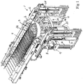
- Figs 1-3 show a coil-forming machine 1 according to an embodiment of the present invention for receiving a series of preformed loops of wire 2 and for accumulating said loops of wire 2 in order to form an upright coil of wire 5 (schematically illustrated in Fig 4 ).
- the preformed loops of wire 2 are delivered to the coil-forming machine 1 laying in an overlapping arrangement on a horizontal conveyor 4, wherein the loops of wire 2 are allowed to fall down into a coil-forming space of the coil-forming machine 1 from a delivery end 3 of the conveyor 4.
- the loops of wire 2 may be delivered to the coil-forming machine in any other suitable manner.
- the coil-forming machine 1 comprises a machine frame 6, which is to be mounted to a floor or other support structure, and one or more support members 7 (see Fig 4 ) for supporting a coil of wire 5 formed in the coil-forming machine.
- Each support member 7 is moveably mounted to the machine frame 6 and vertically moveable in relation to the machine frame 6 by means of an actuator 8, for instance in the form of an electric motor.
- each support member 7 is carried by a holding unit 9, which in its turn is vertically moveable under the effect of the actuator 8 along two vertical guide rails 10 fixed to the machine frame 6.
- the support members 7 and the equipment for moving the support members in relation to the machine frame 6 could also have any other suitable design.
- the coil-forming machine 1 further comprises a wire guiding arrangement 20 which is configured to receive the loops of wire 2 as they fall from the conveyor 4 and guide them towards the support members 7 for the formation of a coil of wire 5 thereon.
- the wire guiding arrangement 20 comprises a housing 21, which is fixed to the machine frame 6 and which defines an upwardly open wire guiding channel 22 (see Figs 2 , 4 and 6 ).
- the housing 21 preferably comprises a tubular wall 23 which delimits the wire guiding channel 22, or at least a section thereof, in radial direction.
- a funnel-shaped inlet portion 24 (see Figs 4 and 6 ) is with advantage provided at an upper end of the wire guiding channel 22 in order to facilitate the entrance of the loops of wire 2 into the wire guiding channel 22.
- a mandrel 25 with a tapered upper end 26 extends vertically through the wire guiding channel 22 at the centre thereof.
- An annular passage for the loops of wire 2 is formed between the envelope surface of the mandrel 25 and the inner surface of the tubular wall 23 and it is thereby ensured that the loops of wire 2 falling downwards through the wire guiding channel 22 will be correctly positioned in relation to the support members 7 and the coil of wire 5 formed thereon.
- the tapered upper end 26 of the mandrel 25 and the funnel-shaped inlet portion 24 will co-operate in guiding the loops of wire 2 into the annular passage between the envelope surface of the mandrel 25 and the inner surface of the tubular wall 23.
- the wire guiding arrangement 20 also comprises a plurality of pivotal guide members 28 distributed about a vertical centre axis 29 (see Figs 4 and 9a ) of the wire guiding channel 22 and an actuating device 30 for pivoting the guide members 28.
- the guide members 28 are preferably six or more in number and evenly distributed about the vertical centre axis 29 of the wire guiding channel 22.
- the wire guiding arrangement 20 is provided with nine guide members 28.
- Each guide member 28 is pivotally mounted to the housing 21 so as to be pivotable into the wire guiding channel 22 towards the centre axis 29 thereof in order to come into contact with loops of wire 2 which are falling downwards through the wire guiding channel 22 and thereby influence the horizontal positioning of these loops of wire 2 in the wire guiding channel 22 and in the coil of wire 5 formed on the support members 7.
- the guide members 28 can be made to displace the loops of wire 2 in a variable and desired manner in relation to the centre axis 29 of the wire guiding channel 22 so as to thereby control the distribution of the loops of wire 2 in the coil of wire 5 formed on the support members 7.
- Each guide member 28 is pivotally mounted to the housing 21 by a joint 31 (see Figs 4 and 6 ) which is provided at an upper end of the guide member 28 and which forms a horizontal pivot axis for the guide member.
- the joints 31 are provided on the outside of the wire guiding channel 22 and each guide member 28 is pivotable into the wire guiding channel 22 through an opening 32 in the tubular wall 23 in order to allow the guide member to hit the outer edge of a loop of wire 2 falling downwards through the wire guiding channel 22 and thereby push the loop of wire sideways.
- the support members 7 may be lowered gradually under the effect of the actuator 8 as the height of the coil of wire 5 formed on the support members 7 increases, to thereby keep the upper end of the coil of wire 5 at a given level below the guide members 28.
- the above-mentioned actuating device 30 comprises an annular actuating member 34, which preferably has the form of a closed ring.
- the actuating member 34 may have the form of an open ring.
- the actuating member 34 is designed as a circular ring, but it may as an alternative be designed as a polygonal ring.
- the actuating member 34 surrounds the wire guiding channel 22.
- the actuating member 34 extends around the tubular wall 23 at a distance therefrom.
- the actuating member 34 could as an alternative be located at a level below the lower end of the wire guiding channel 22.
- the actuating device 30 further comprises:
- the actuators 35 are distributed, preferably evenly, about the centre axis of the actuating member 34.
- the set of actuators preferably comprises three actuators 35 evenly distributed about the centre axis of the actuating member 34. Thus, in the latter case the angles between the actuators 35 are 120°.
- the actuators 35 are controlled by an electronic control unit (not shown) in order to move the actuating member 34 in a desired manner in relation to the housing 21 and thereby pivot the guide members 28 in a desired manner.
- the actuating member 34 is arranged to be tiltable in relation to the housing 21 in any desired direction under the effect of the actuators 35 and is preferably also arranged to be vertically moveable in relation to the housing 21 under the effect of the actuators 35. In the illustrated embodiment, the actuating member 34 is suspended from the actuators 35.
- Two lateral supports 44 are with advantage provided between the actuating member 34 and the housing 21 in order to prevent uncontrolled lateral movements of the actuating member 34 in relation to the housing 21.
- the lateral supports 44 are arranged at two different locations as seen in the circumferential direction of the actuating member 34.
- Each lateral support 44 consists of a link which at a first end is articulately connected to the actuating member 34 by a joint 45, preferably in the form of a ball joint or spherical bearing, and at an opposite second end is articulately connected to the housing 21 by another joint (not shown), preferably in the form of a ball joint or spherical bearing.
- Each actuator 35 preferably has the form of a pneumatic or hydraulic cylinder.
- each actuator 35 is a hydraulic cylinder with a cylinder part 35a and a piston (not shown) received in the cylinder part 35a, wherein the piston is displaceable in relation to the cylinder part 35a and fixed to a piston rod 35b.
- the cylinder part 35a is articulately connected to the housing 21 by a joint 38a, preferably in the form of a ball joint or spherical bearing
- the associated piston rod 35b is articulately connected to the actuating member 34 by another joint 38b, preferably in the form of a ball joint or spherical bearing.
- each actuator could comprise an electric motor and a motion transferring mechanism, for instance in the form of a crank arm, for transferring a rotary motion of an output shaft of the electric motor or an associated gearing into a vertical movement of a link which is articulately connected to the actuating member 34 by a joint in the form of a ball joint or spherical bearing.
- the above-mentioned joint 38a between the housing 21 and an actuator 35 is provided at the outer end of a horizontally extending arm 39 of a bracket 40, which is fixed to the tubular wall 23 on the outside thereof.
- each link mechanism 36 comprises:
- the link mechanisms 36 may of course also have any other suitable configuration, as long as they are capable of transferring a tilting or vertical movement of the actuating member 34 into a corresponding pivotal movement of the guide members 28.
- Figs 8a-8c and 9a-9c illustrates how the actuators 35 may control the pivotal positions of the guide members 28 by tilting the actuating member 34 or moving the actuating member 34 in vertical direction.
- Figs 8a and 9a show the wire guiding arrangement 20 with the actuating member 34 horizontally arranged in a lower end position, wherein all guide members 28 are pivoted into the wire guiding channel 22 to a maximum extent.
- the guide members 28 When the guide members 28 are in this position, they are capable of stopping the loops of wire 2 which are falling downwards through the wire guiding channel 22, and it is thereby possible, when so needed, to accumulate a desired number of loops of wire 2 on the guide members 28 before the guide members are retracted in order to allow these loops of wire to drop down onto the support members 7.
- Figs 8c and 9c show the wire guiding arrangement 20 with the actuating member 34 horizontally arranged in an upper end position, wherein none of the guide members 28 is pivoted into the wire guiding channel 22.
- loops of wire 2 may fall downwards through the wire guiding channel 22 without coming into contact with any of the guide members 28, i.e. without being subjected to any guiding action from the guide members 28.
- Figs 8b and 9b show the wire guiding arrangement 20 with the actuating member 34 tilted and arranged between the above-mentioned lower and upper end positions, whereby the guide members 28 are pivoted into the wire guiding channel 22 to different extents so as to thereby push a passing loop of wire 2 horizontally in order to make the loop of wire assume an eccentric position in relation to the centre axis 29 of the wire guiding channel 22.
- the actuators 35 can be made to continuously vary the inclination of the actuating member 34 as desired to thereby continuously vary the direction in which the loops of wire 2 are pushed by the guide members 28 when passing through the wire guiding channel 22.
- the frequency and/or amplitude in which the actuating member 34 is tilted by the actuators 35 may be adjusted as desired in order to control the manner in which the guide members 28 act on the loops of wire 2 which are falling downwards through the wire guiding channel 22.
Landscapes
- Engineering & Computer Science (AREA)
- Mechanical Engineering (AREA)
- Coiling Of Filamentary Materials In General (AREA)
- Manufacture Of Motors, Generators (AREA)
Abstract
- a housing (21) defining a wire guiding channel (22);
- guide members (28) pivotally mounted to the housing so as to be pivotable into the wire guiding channel in order to come into contact with loops of wire falling downwards through the wire guiding channel; and
- an actuating device (30) comprising:
• an annular actuating member (34);
• actuators (35) for tilting the actuating member (34) in relation to the housing (21); and
• link mechanisms (36) which connect the guide members (28) to the actuating member (34) to thereby allow the actuators (35) to control the pivotal positions of the guide members via the actuating member and the link mechanisms.
Description
- The present invention relates to a coil-forming machine according to the preamble of claim 1 for receiving a series of preformed loops of wire and for accumulating said loops of wire in order to form an upright coil of wire.
- In this description and the subsequent claims, the term "wire" encompasses metallic wires of thinner type as well as metallic wire rods.
- Metallic wire produced in a rolling mill is normally accumulated in coils of essentially cylindrical configuration in a coil-forming machine, whereupon the coils can be compacted and bound in order to facilitate subsequent storing and transportation of the coils. It is a common practice to deliver the rolled wire to the coil-forming machine with the rolled wire arranged in the form of overlapping loops laying on an essentially horizontal conveyor, wherein the loops of wire at the end of the conveyor are allowed to fall vertically downwards from the conveyor into an upwardly open coil-forming chamber provided in the coil-forming machine.
- Various forms of coil-forming machines of the above-mentioned type for receiving a series of preformed loops of wire falling from a delivery end of a conveyor and for accumulating said loops of wire in order to form an upright coil of wire have been proposed and come into use. A coil-forming machine according to the preamble of claim 1 is for instance previously known from
US 6 158 683 A . This previously known coil-forming machine is provided with pivotal guide members for influencing the horizontal positioning of the loops of wire as they fall downwards through the coil-forming chamber so that they drop somewhat eccentrically with respect to the centre axis of the coil-forming chamber and are distributed in a desired pattern in the formed coil of wire so as to thereby improve the stability and compactness of the coil. In the coil-forming machine according toUS 6 158 683 A , each guide member may be provided with its own actuator in the form of an eccentric motor or a pneumatic or hydraulic cylinder for controlling the pivotal position of the guide member. This solution is not very appropriate when there is a desire to use a larger number of guide members, in view of the fact that a large number of guide members would also require a large number of actuators, which in its turn would imply an increased cost for the machine and require a rather complex control system for controlling the actuators.US 6 158 683 A also discloses an embodiment where the pivotal positions of all guide members are controlled by the rotation of an annular actuating member, wherein the actuating member on its inner side is provided with an annular eccentric guide cam which acts on each individual guide member via a horizontally moveable actuating rod provided with a cam follower roller at its outer end. A disadvantage with the last-mentioned solution is that it does not offer any possibility to vary the sequence in which the guide members are moved, since the guide members can only be moved in accordance with one single predetermined sequence of movements given by the design of the guide cam. - The object of the present invention is to provide a coil-forming machine of new and favourable design, which in at least some aspect offers an advantage as compared to previously known coil-forming machines.
- According to the invention, this object is achieved by a coil-forming machine having the features defined in claim 1.
- The coil-forming machine according to the present invention comprises:
- one or more support members for supporting a coil of wire formed in the coil-forming machine; and
- a wire guiding arrangement, wherein the wire guiding arrangement comprises:
- a housing which defines an upwardly open wire guiding channel,
- a plurality of pivotal guide members distributed about a vertical centre axis of the wire guiding channel, wherein each guide member is pivotally mounted to the housing so as to be pivotable into the wire guiding channel towards the centre axis thereof in order to come into contact with loops of wire which are falling downwards through the wire guiding channel towards said support member or members and thereby influence the horizontal positioning of these loops of wire in the wire guiding channel and in the coil of wire formed on said support member or members, and
- an actuating device for pivoting the guide members.
- The above-mentioned actuating device comprises:
- an annular actuating member;
- a set of actuators connected to the actuating member, wherein the actuating member is tiltable in relation to the housing under the effect of the actuators; and
- a plurality of link mechanisms, wherein each link mechanism forms a connection between one of the guide members and the actuating member to thereby allow the actuators to control the pivotal positions of the guide members via the actuating member and the link mechanisms.
- With the coil-forming machine of the present invention, the pivotal positions of all guide members may be controlled by tilting the annular actuating member, which can be achieved in a rapid and simple manner by means of a limited number of actuators. Hereby, it will be possible to control the pivotal positions of a large number of pivotal guide members by means of rather few actuators, at the same time as the pivoting movements of the guide members easily can be varied by altering the frequency and/or amplitude of the tilting movements of the actuating member.
- According to an embodiment of the invention, the actuating member is also vertically moveable in relation to the housing under the effect of the actuators. Hereby, the pivotal position of all the guide members may also be simultaneously changed by a vertical movement of the actuating member.
- According to another embodiment of the invention, the set of actuators comprises three actuators distributed about a centre axis of the actuating member. Three actuators distributed about the centre axis of the actuating member will be sufficient for controlling the inclination and vertical position of the annular actuating member in an accurate manner.
- According to another embodiment of the invention, each actuator has the form of a pneumatic or hydraulic cylinder. The use of actuators in the form of pneumatic or hydraulic cylinder will make it possible to give the actuating device a simple and reliable construction.
- Further advantages as well as advantageous features of the coil-forming machine according to the present invention will appear from the following description and the dependent claims.
- With reference to the appended drawings, a specific description of preferred embodiments of the invention cited as examples follows below. In the drawings:
- Fig 1
- is a perspective view of a coil-forming machine according to an embodiment of the present invention,
- Fig 2
- is a planar view from above of the coil-forming machine of
Fig 1 , - Fig 3
- is a lateral view of the coil-forming machine of
Fig 1 , - Fig 4
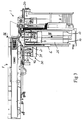
- is a vertical section according to the line IV-IV in
Fig 3 , - Fig 5
- is a perspective view from below of a wire guiding arrangement included in the coil-forming machine of
Fig 1 , - Fig 6
- is a perspective view from above of the wire guiding arrangement of
Fig 5 , - Fig 7
- is a perspective view corresponding to
Fig 6 , but with the housing of the wire guiding arrangement omitted, - Figs 8a-8c
- are lateral views of the wire guiding arrangement of
Fig 5 , with the annular actuating member of the wire guiding arrangement shown in different positions, and - Figs 9a-9c
- are planar views from above of the wire guiding arrangement of
Fig 5 , with the moveable components of the wire guiding arrangement shown in positions corresponding to the positions according toFigs 8a-8c . -
Figs 1-3 show a coil-forming machine 1 according to an embodiment of the present invention for receiving a series of preformed loops ofwire 2 and for accumulating said loops ofwire 2 in order to form an upright coil of wire 5 (schematically illustrated inFig 4 ). In the illustrated example, the preformed loops ofwire 2 are delivered to the coil-forming machine 1 laying in an overlapping arrangement on ahorizontal conveyor 4, wherein the loops ofwire 2 are allowed to fall down into a coil-forming space of the coil-forming machine 1 from adelivery end 3 of theconveyor 4. However, the loops ofwire 2 may be delivered to the coil-forming machine in any other suitable manner. - The coil-forming machine 1 comprises a
machine frame 6, which is to be mounted to a floor or other support structure, and one or more support members 7 (seeFig 4 ) for supporting a coil ofwire 5 formed in the coil-forming machine. In the illustrated embodiment, there are twosuch support members 7. Eachsupport member 7 is moveably mounted to themachine frame 6 and vertically moveable in relation to themachine frame 6 by means of an actuator 8, for instance in the form of an electric motor. In the illustrated example, eachsupport member 7 is carried by aholding unit 9, which in its turn is vertically moveable under the effect of the actuator 8 along twovertical guide rails 10 fixed to themachine frame 6. However, thesupport members 7 and the equipment for moving the support members in relation to themachine frame 6 could also have any other suitable design. - The coil-forming machine 1 further comprises a
wire guiding arrangement 20 which is configured to receive the loops ofwire 2 as they fall from theconveyor 4 and guide them towards thesupport members 7 for the formation of a coil ofwire 5 thereon. Thewire guiding arrangement 20 comprises ahousing 21, which is fixed to themachine frame 6 and which defines an upwardly open wire guiding channel 22 (seeFigs 2 ,4 and6 ). Thehousing 21 preferably comprises atubular wall 23 which delimits thewire guiding channel 22, or at least a section thereof, in radial direction. A funnel-shaped inlet portion 24 (seeFigs 4 and6 ) is with advantage provided at an upper end of thewire guiding channel 22 in order to facilitate the entrance of the loops ofwire 2 into thewire guiding channel 22. - A
mandrel 25 with a taperedupper end 26 extends vertically through thewire guiding channel 22 at the centre thereof. An annular passage for the loops ofwire 2 is formed between the envelope surface of themandrel 25 and the inner surface of thetubular wall 23 and it is thereby ensured that the loops ofwire 2 falling downwards through thewire guiding channel 22 will be correctly positioned in relation to thesupport members 7 and the coil ofwire 5 formed thereon. The taperedupper end 26 of themandrel 25 and the funnel-shapedinlet portion 24 will co-operate in guiding the loops ofwire 2 into the annular passage between the envelope surface of themandrel 25 and the inner surface of thetubular wall 23. - The
wire guiding arrangement 20 also comprises a plurality ofpivotal guide members 28 distributed about a vertical centre axis 29 (seeFigs 4 and9a ) of thewire guiding channel 22 and anactuating device 30 for pivoting theguide members 28. Theguide members 28 are preferably six or more in number and evenly distributed about thevertical centre axis 29 of thewire guiding channel 22. In the illustrated embodiment, thewire guiding arrangement 20 is provided with nineguide members 28. Eachguide member 28 is pivotally mounted to thehousing 21 so as to be pivotable into thewire guiding channel 22 towards thecentre axis 29 thereof in order to come into contact with loops ofwire 2 which are falling downwards through thewire guiding channel 22 and thereby influence the horizontal positioning of these loops ofwire 2 in thewire guiding channel 22 and in the coil ofwire 5 formed on thesupport members 7. Theguide members 28 can be made to displace the loops ofwire 2 in a variable and desired manner in relation to thecentre axis 29 of thewire guiding channel 22 so as to thereby control the distribution of the loops ofwire 2 in the coil ofwire 5 formed on thesupport members 7. - Each
guide member 28 is pivotally mounted to thehousing 21 by a joint 31 (seeFigs 4 and6 ) which is provided at an upper end of theguide member 28 and which forms a horizontal pivot axis for the guide member. Thejoints 31 are provided on the outside of thewire guiding channel 22 and eachguide member 28 is pivotable into thewire guiding channel 22 through anopening 32 in thetubular wall 23 in order to allow the guide member to hit the outer edge of a loop ofwire 2 falling downwards through thewire guiding channel 22 and thereby push the loop of wire sideways. - The
support members 7 may be lowered gradually under the effect of the actuator 8 as the height of the coil ofwire 5 formed on thesupport members 7 increases, to thereby keep the upper end of the coil ofwire 5 at a given level below theguide members 28. - The above-mentioned
actuating device 30 comprises anannular actuating member 34, which preferably has the form of a closed ring. As an alternative, the actuatingmember 34 may have the form of an open ring. In the illustrated embodiment, the actuatingmember 34 is designed as a circular ring, but it may as an alternative be designed as a polygonal ring. - In the illustrated embodiment, the actuating
member 34 surrounds thewire guiding channel 22. Thus, in this case, the actuatingmember 34 extends around thetubular wall 23 at a distance therefrom. However, the actuatingmember 34 could as an alternative be located at a level below the lower end of thewire guiding channel 22. - The
actuating device 30 further comprises: - a set of
actuators 35 connected to the actuatingmember 34 for controlling the position thereof; and - a plurality of
link mechanisms 36, wherein eachlink mechanism 36 forms a connection between one of theguide members 28 and the actuatingmember 34 to thereby allow theactuators 35 to control the pivotal positions of theguide members 28 via the actuatingmember 34 and thelink mechanisms 36. - The
actuators 35 are distributed, preferably evenly, about the centre axis of the actuatingmember 34. The set of actuators preferably comprises threeactuators 35 evenly distributed about the centre axis of the actuatingmember 34. Thus, in the latter case the angles between theactuators 35 are 120°. Theactuators 35 are controlled by an electronic control unit (not shown) in order to move the actuatingmember 34 in a desired manner in relation to thehousing 21 and thereby pivot theguide members 28 in a desired manner. The actuatingmember 34 is arranged to be tiltable in relation to thehousing 21 in any desired direction under the effect of theactuators 35 and is preferably also arranged to be vertically moveable in relation to thehousing 21 under the effect of theactuators 35. In the illustrated embodiment, the actuatingmember 34 is suspended from theactuators 35. - Two lateral supports 44 (see
Figs 5-7 ) are with advantage provided between the actuatingmember 34 and thehousing 21 in order to prevent uncontrolled lateral movements of the actuatingmember 34 in relation to thehousing 21. The lateral supports 44 are arranged at two different locations as seen in the circumferential direction of the actuatingmember 34. Eachlateral support 44 consists of a link which at a first end is articulately connected to the actuatingmember 34 by a joint 45, preferably in the form of a ball joint or spherical bearing, and at an opposite second end is articulately connected to thehousing 21 by another joint (not shown), preferably in the form of a ball joint or spherical bearing. - Each
actuator 35 preferably has the form of a pneumatic or hydraulic cylinder. In the illustrated embodiment, each actuator 35 is a hydraulic cylinder with acylinder part 35a and a piston (not shown) received in thecylinder part 35a, wherein the piston is displaceable in relation to thecylinder part 35a and fixed to apiston rod 35b. Thecylinder part 35a is articulately connected to thehousing 21 by a joint 38a, preferably in the form of a ball joint or spherical bearing, and the associatedpiston rod 35b is articulately connected to the actuatingmember 34 by another joint 38b, preferably in the form of a ball joint or spherical bearing. As an alternative, thecylinder part 35a may be articulately connected to the actuatingmember 34 and thepiston rod 35b articulately connected to thehousing 21. It would also be possible to use other types of actuators for moving the actuatingmember 34, such as for instance electromechanical actuators. As a further alternative, each actuator could comprise an electric motor and a motion transferring mechanism, for instance in the form of a crank arm, for transferring a rotary motion of an output shaft of the electric motor or an associated gearing into a vertical movement of a link which is articulately connected to the actuatingmember 34 by a joint in the form of a ball joint or spherical bearing. - In the illustrated example, the above-mentioned joint 38a between the
housing 21 and anactuator 35 is provided at the outer end of a horizontally extendingarm 39 of abracket 40, which is fixed to thetubular wall 23 on the outside thereof. - In the illustrated embodiment, each
link mechanism 36 comprises: - an
arm 41 which is fixed to the associatedguide member 28 at an upper end thereof and extends at an angle from theguide member 28, wherein thearm 41 faces away from thewire guiding channel 22; and - a
link 42 which at a first end is articulately connected to saidarm 41 by a joint 43a, preferably in the form of a ball joint or spherical bearing, and at an opposite second end is articulately connected to the actuatingmember 34 by another joint 43b, preferably in the form of a ball joint or spherical bearing. - The
link mechanisms 36 may of course also have any other suitable configuration, as long as they are capable of transferring a tilting or vertical movement of the actuatingmember 34 into a corresponding pivotal movement of theguide members 28. -
Figs 8a-8c and 9a-9c illustrates how theactuators 35 may control the pivotal positions of theguide members 28 by tilting the actuatingmember 34 or moving the actuatingmember 34 in vertical direction. -
Figs 8a and 9a show thewire guiding arrangement 20 with the actuatingmember 34 horizontally arranged in a lower end position, wherein allguide members 28 are pivoted into thewire guiding channel 22 to a maximum extent. When theguide members 28 are in this position, they are capable of stopping the loops ofwire 2 which are falling downwards through thewire guiding channel 22, and it is thereby possible, when so needed, to accumulate a desired number of loops ofwire 2 on theguide members 28 before the guide members are retracted in order to allow these loops of wire to drop down onto thesupport members 7. -
Figs 8c and 9c show thewire guiding arrangement 20 with the actuatingmember 34 horizontally arranged in an upper end position, wherein none of theguide members 28 is pivoted into thewire guiding channel 22. When theguide members 28 are in this position, loops ofwire 2 may fall downwards through thewire guiding channel 22 without coming into contact with any of theguide members 28, i.e. without being subjected to any guiding action from theguide members 28. -
Figs 8b and 9b show thewire guiding arrangement 20 with the actuatingmember 34 tilted and arranged between the above-mentioned lower and upper end positions, whereby theguide members 28 are pivoted into thewire guiding channel 22 to different extents so as to thereby push a passing loop ofwire 2 horizontally in order to make the loop of wire assume an eccentric position in relation to thecentre axis 29 of thewire guiding channel 22. Theactuators 35 can be made to continuously vary the inclination of the actuatingmember 34 as desired to thereby continuously vary the direction in which the loops ofwire 2 are pushed by theguide members 28 when passing through thewire guiding channel 22. The frequency and/or amplitude in which the actuatingmember 34 is tilted by theactuators 35 may be adjusted as desired in order to control the manner in which theguide members 28 act on the loops ofwire 2 which are falling downwards through thewire guiding channel 22. - The invention is of course not in any way restricted to the embodiments described above. On the contrary, many possibilities to modifications thereof will be apparent to a person with ordinary skill in the art without departing from the basic idea of the invention such as defined in the appended claims.
Claims (14)
- A coil-forming machine for receiving a series of preformed loops of wire (2) and for accumulating said loops of wire (2) in order to form an upright coil of wire (5), the coil-forming machine (1) comprising:- one or more support members (7) for supporting a coil of wire (5) formed in the coil-forming machine (1); and- a wire guiding arrangement (20), wherein the wire guiding arrangement comprises:characterized in that the actuating device (30) comprises:• a housing (21) which defines an upwardly open wire guiding channel (22),• a plurality of pivotal guide members (28) distributed about a vertical centre axis (29) of the wire guiding channel (22), wherein each guide member (28) is pivotally mounted to the housing (21) so as to be pivotable into the wire guiding channel (22) towards the centre axis (29) thereof in order to come into contact with loops of wire (2) which are falling downwards through the wire guiding channel (22) towards said support member or members (7) and thereby influence the horizontal positioning of these loops of wire (2) in the wire guiding channel (22) and in the coil of wire (5) formed on said support member or members (7), and• an actuating device (30) for pivoting the guide members (28),- an annular actuating member (34);- a set of actuators (35) connected to the actuating member (34), wherein the actuating member (34) is tiltable in relation to the housing (21) under the effect of the actuators (35); and- a plurality of link mechanisms (36), wherein each link mechanism (36) forms a connection between one of the guide members (28) and the actuating member (34) to thereby allow the actuators (35) to control the pivotal positions of the guide members (28) via the actuating member (34) and the link mechanisms (36).
- A coil-forming machine according to claim 1, characterized in that the actuating member (34) is also vertically moveable in relation to the housing (21) under the effect of the actuators (35).
- A coil-forming machine according to claim 1 or 2, characterized in that the set of actuators comprises three actuators (35) distributed about a centre axis of the actuating member (34).
- A coil-forming machine according to claim 3, characterized in that the actuators (35) are evenly distributed about the centre axis of the actuating member (34).
- A coil-forming machine according to any of claims 1-4, characterized in that each actuator (35) has the form of a pneumatic or hydraulic cylinder.
- A coil-forming machine according to claim 5, characterized in that said pneumatic or hydraulic cylinder has a cylinder part (35a) articulately connected to the housing (21) by a joint (38a), preferably in the form of a ball joint or spherical bearing, and an associated piston rod (35b) articulately connected to the actuating member (34) by another joint (38b), preferably in the form of a ball joint or spherical bearing.
- A coil-forming machine according to any of claims 1-6, characterized in that the actuating member (34) is suspended from the actuators (35).
- A coil-forming machine according to any of claims 1-7, characterized in that the actuating member (34) surrounds the wire guiding channel (22).
- A coil-forming machine according to any of claims 1-8, characterized in that each link mechanism (36) comprises:- an arm (41) which is fixed to the associated guide member (28) at an upper end thereof and extends at an angle from the guide member (28), wherein the arm (41) faces away from the wire guiding channel (22); and- a link (42) which at a first end is articulately connected to said arm (41) by a joint (43a), preferably in the form of a ball joint or spherical bearing, and at an opposite second end is articulately connected to the actuating member (34) by another joint (43b), preferably in the form of a ball joint or spherical bearing.
- A coil-forming machine according to any of claims 1-9, characterized in:- that the housing (21) comprises a tubular wall (23) which delimits the wire guiding channel (22) or at least a section thereof in radial direction; and- that the guide members (28) are pivotable into the wire guiding channel (22) through openings (32) in the tubular wall (23).
- A coil-forming machine according to any of claims 1-10, characterized in that each guide member (28) is pivotally mounted to the housing by a joint (31) which is provided at an upper end of the guide member (28) and which forms a horizontal pivot axis for the guide member.
- A coil-forming machine according to any of claims 1-11, characterized in that a funnel-shaped inlet portion (24) is provided at an upper end of the wire guiding channel (22).
- A coil-forming machine according to any of claims 1-12, characterized in that the coil-forming machine (1) comprises a mandrel (25) with a tapered upper end (26), wherein the mandrel (25) extends vertically through the wire guiding channel (22) at the centre thereof.
- A coil-forming machine according to any of claims 1-13, characterized in:- that said one or more support members (28) are vertically moveable in relation to the housing (21); and- that the coil-forming machine (1) comprises one or more actuators (8) for moving said one or more support members (7) vertically in relation to the housing (21).
Priority Applications (3)
| Application Number | Priority Date | Filing Date | Title |
|---|---|---|---|
| ES16175294T ES2741786T3 (en) | 2016-06-20 | 2016-06-20 | Coil forming machine |
| EP16175294.4A EP3260212B1 (en) | 2016-06-20 | 2016-06-20 | Coil-forming machine |
| PCT/EP2017/062877 WO2017220288A1 (en) | 2016-06-20 | 2017-05-29 | Coil-forming machine |
Applications Claiming Priority (1)
| Application Number | Priority Date | Filing Date | Title |
|---|---|---|---|
| EP16175294.4A EP3260212B1 (en) | 2016-06-20 | 2016-06-20 | Coil-forming machine |
Publications (2)
| Publication Number | Publication Date |
|---|---|
| EP3260212A1 true EP3260212A1 (en) | 2017-12-27 |
| EP3260212B1 EP3260212B1 (en) | 2019-05-15 |
Family
ID=56148228
Family Applications (1)
| Application Number | Title | Priority Date | Filing Date |
|---|---|---|---|
| EP16175294.4A Not-in-force EP3260212B1 (en) | 2016-06-20 | 2016-06-20 | Coil-forming machine |
Country Status (3)
| Country | Link |
|---|---|
| EP (1) | EP3260212B1 (en) |
| ES (1) | ES2741786T3 (en) |
| WO (1) | WO2017220288A1 (en) |
Citations (7)
| Publication number | Priority date | Publication date | Assignee | Title |
|---|---|---|---|---|
| JPH05329538A (en) * | 1991-04-22 | 1993-12-14 | Sumitomo Heavy Ind Ltd | Loose winding device in wire rod bundling device |
| EP0686438A1 (en) * | 1994-06-07 | 1995-12-13 | DANIELI & C. OFFICINE MECCANICHE S.p.A. | Device for the asymmetric depositing of loops |
| DE19620578A1 (en) * | 1996-05-22 | 1997-11-27 | Thaelmann Schwermaschbau Veb | Wire coil former for wire mill |
| DE19704421A1 (en) * | 1997-02-06 | 1998-08-13 | Schloemann Siemag Ag | Apparatus for forming bundles from loops of rolled wire |
| US6158683A (en) | 1998-03-18 | 2000-12-12 | Sms Schloemann-Siemag Ag | Apparatus for forming rolled wire-rod coil |
| DE10026583A1 (en) * | 2000-05-30 | 2001-12-13 | Sket Walzwerkstechnik Gmbh | Device to form wire windings into wire coil; has coil separator with evenly spaced centring flaps to centre wire windings, which are moved tranversely and stacked in vertical collection shaft |
| EP1201327A2 (en) * | 2000-10-25 | 2002-05-02 | SMS Demag AG | Device for influencing the fall-position of wire loops dropped in a coil forming device |
-
2016
- 2016-06-20 EP EP16175294.4A patent/EP3260212B1/en not_active Not-in-force
- 2016-06-20 ES ES16175294T patent/ES2741786T3/en active Active
-
2017
- 2017-05-29 WO PCT/EP2017/062877 patent/WO2017220288A1/en not_active Ceased
Patent Citations (7)
| Publication number | Priority date | Publication date | Assignee | Title |
|---|---|---|---|---|
| JPH05329538A (en) * | 1991-04-22 | 1993-12-14 | Sumitomo Heavy Ind Ltd | Loose winding device in wire rod bundling device |
| EP0686438A1 (en) * | 1994-06-07 | 1995-12-13 | DANIELI & C. OFFICINE MECCANICHE S.p.A. | Device for the asymmetric depositing of loops |
| DE19620578A1 (en) * | 1996-05-22 | 1997-11-27 | Thaelmann Schwermaschbau Veb | Wire coil former for wire mill |
| DE19704421A1 (en) * | 1997-02-06 | 1998-08-13 | Schloemann Siemag Ag | Apparatus for forming bundles from loops of rolled wire |
| US6158683A (en) | 1998-03-18 | 2000-12-12 | Sms Schloemann-Siemag Ag | Apparatus for forming rolled wire-rod coil |
| DE10026583A1 (en) * | 2000-05-30 | 2001-12-13 | Sket Walzwerkstechnik Gmbh | Device to form wire windings into wire coil; has coil separator with evenly spaced centring flaps to centre wire windings, which are moved tranversely and stacked in vertical collection shaft |
| EP1201327A2 (en) * | 2000-10-25 | 2002-05-02 | SMS Demag AG | Device for influencing the fall-position of wire loops dropped in a coil forming device |
Also Published As
| Publication number | Publication date |
|---|---|
| WO2017220288A1 (en) | 2017-12-28 |
| EP3260212B1 (en) | 2019-05-15 |
| ES2741786T3 (en) | 2020-02-12 |
Similar Documents
| Publication | Publication Date | Title |
|---|---|---|
| US11885051B2 (en) | Braiding machine and methods of use | |
| CN105792959B (en) | The equipment of the steel reinforcement cage of tower section for manufacturing wind power plant | |
| JP2017517403A (en) | Electronic device production system | |
| DE4112435C2 (en) | Cop delivery station | |
| EP3260212B1 (en) | Coil-forming machine | |
| RU2067038C1 (en) | Apparatus for horizontal distribution of rod turns in installation for forming ring-like coil | |
| CN1145989C (en) | Coil forming apparatus and method | |
| US9945644B2 (en) | Machine for launching targets and its adjustment method | |
| CN113328591B (en) | Winding system of motor coil | |
| US10161202B2 (en) | Drill rod store, drilling rig and method for downward drilling | |
| DE2741534C2 (en) | Process for the manufacture of coil springs with eyelets from wire and a machine for carrying out the process | |
| EP3223411A1 (en) | Machine for performing wire windings on cores arranged on the internal lateral surface of cylindrical stators for electric motors | |
| JP2019513020A (en) | Milking module, milking device and method for milking a herd of animals | |
| JPH09510179A (en) | Gob Feeder for I.S. Glassware Forming Machine | |
| US6158683A (en) | Apparatus for forming rolled wire-rod coil | |
| KR102530301B1 (en) | Bending apparatus for pipe | |
| US3944158A (en) | Collecting device for producing long wire rod coils | |
| EP1176283A2 (en) | Mobile drilling unit | |
| US5727504A (en) | Milking stand | |
| JP3355323B2 (en) | Wire coil concentrator | |
| EP3669635B1 (en) | Combine header with adjustable reel | |
| CN117016192B (en) | Picking device | |
| US20060163034A1 (en) | Machine for straightening and aligning plastic vessels | |
| JPH10166050A (en) | Wire coil reforming equipment | |
| JP3268425B2 (en) | Wire coil concentrator |
Legal Events
| Date | Code | Title | Description |
|---|---|---|---|
| PUAI | Public reference made under article 153(3) epc to a published international application that has entered the european phase |
Free format text: ORIGINAL CODE: 0009012 |
|
| STAA | Information on the status of an ep patent application or granted ep patent |
Free format text: STATUS: THE APPLICATION HAS BEEN PUBLISHED |
|
| AK | Designated contracting states |
Kind code of ref document: A1 Designated state(s): AL AT BE BG CH CY CZ DE DK EE ES FI FR GB GR HR HU IE IS IT LI LT LU LV MC MK MT NL NO PL PT RO RS SE SI SK SM TR |
|
| AX | Request for extension of the european patent |
Extension state: BA ME |
|
| STAA | Information on the status of an ep patent application or granted ep patent |
Free format text: STATUS: REQUEST FOR EXAMINATION WAS MADE |
|
| 17P | Request for examination filed |
Effective date: 20180615 |
|
| RBV | Designated contracting states (corrected) |
Designated state(s): AL AT BE BG CH CY CZ DE DK EE ES FI FR GB GR HR HU IE IS IT LI LT LU LV MC MK MT NL NO PL PT RO RS SE SI SK SM TR |
|
| GRAP | Despatch of communication of intention to grant a patent |
Free format text: ORIGINAL CODE: EPIDOSNIGR1 |
|
| STAA | Information on the status of an ep patent application or granted ep patent |
Free format text: STATUS: GRANT OF PATENT IS INTENDED |
|
| INTG | Intention to grant announced |
Effective date: 20181205 |
|
| GRAS | Grant fee paid |
Free format text: ORIGINAL CODE: EPIDOSNIGR3 |
|
| GRAA | (expected) grant |
Free format text: ORIGINAL CODE: 0009210 |
|
| STAA | Information on the status of an ep patent application or granted ep patent |
Free format text: STATUS: THE PATENT HAS BEEN GRANTED |
|
| AK | Designated contracting states |
Kind code of ref document: B1 Designated state(s): AL AT BE BG CH CY CZ DE DK EE ES FI FR GB GR HR HU IE IS IT LI LT LU LV MC MK MT NL NO PL PT RO RS SE SI SK SM TR |
|
| REG | Reference to a national code |
Ref country code: CH Ref legal event code: EP |
|
| REG | Reference to a national code |
Ref country code: DE Ref legal event code: R096 Ref document number: 602016013881 Country of ref document: DE |
|
| REG | Reference to a national code |
Ref country code: IE Ref legal event code: FG4D |
|
| REG | Reference to a national code |
Ref country code: NL Ref legal event code: MP Effective date: 20190515 |
|
| REG | Reference to a national code |
Ref country code: LT Ref legal event code: MG4D |
|
| PG25 | Lapsed in a contracting state [announced via postgrant information from national office to epo] |
Ref country code: AL Free format text: LAPSE BECAUSE OF FAILURE TO SUBMIT A TRANSLATION OF THE DESCRIPTION OR TO PAY THE FEE WITHIN THE PRESCRIBED TIME-LIMIT Effective date: 20190515 Ref country code: PT Free format text: LAPSE BECAUSE OF FAILURE TO SUBMIT A TRANSLATION OF THE DESCRIPTION OR TO PAY THE FEE WITHIN THE PRESCRIBED TIME-LIMIT Effective date: 20190915 Ref country code: NL Free format text: LAPSE BECAUSE OF FAILURE TO SUBMIT A TRANSLATION OF THE DESCRIPTION OR TO PAY THE FEE WITHIN THE PRESCRIBED TIME-LIMIT Effective date: 20190515 Ref country code: LT Free format text: LAPSE BECAUSE OF FAILURE TO SUBMIT A TRANSLATION OF THE DESCRIPTION OR TO PAY THE FEE WITHIN THE PRESCRIBED TIME-LIMIT Effective date: 20190515 Ref country code: NO Free format text: LAPSE BECAUSE OF FAILURE TO SUBMIT A TRANSLATION OF THE DESCRIPTION OR TO PAY THE FEE WITHIN THE PRESCRIBED TIME-LIMIT Effective date: 20190815 Ref country code: HR Free format text: LAPSE BECAUSE OF FAILURE TO SUBMIT A TRANSLATION OF THE DESCRIPTION OR TO PAY THE FEE WITHIN THE PRESCRIBED TIME-LIMIT Effective date: 20190515 Ref country code: SE Free format text: LAPSE BECAUSE OF FAILURE TO SUBMIT A TRANSLATION OF THE DESCRIPTION OR TO PAY THE FEE WITHIN THE PRESCRIBED TIME-LIMIT Effective date: 20190515 Ref country code: FI Free format text: LAPSE BECAUSE OF FAILURE TO SUBMIT A TRANSLATION OF THE DESCRIPTION OR TO PAY THE FEE WITHIN THE PRESCRIBED TIME-LIMIT Effective date: 20190515 |
|
| PG25 | Lapsed in a contracting state [announced via postgrant information from national office to epo] |
Ref country code: RS Free format text: LAPSE BECAUSE OF FAILURE TO SUBMIT A TRANSLATION OF THE DESCRIPTION OR TO PAY THE FEE WITHIN THE PRESCRIBED TIME-LIMIT Effective date: 20190515 Ref country code: LV Free format text: LAPSE BECAUSE OF FAILURE TO SUBMIT A TRANSLATION OF THE DESCRIPTION OR TO PAY THE FEE WITHIN THE PRESCRIBED TIME-LIMIT Effective date: 20190515 Ref country code: GR Free format text: LAPSE BECAUSE OF FAILURE TO SUBMIT A TRANSLATION OF THE DESCRIPTION OR TO PAY THE FEE WITHIN THE PRESCRIBED TIME-LIMIT Effective date: 20190816 Ref country code: BG Free format text: LAPSE BECAUSE OF FAILURE TO SUBMIT A TRANSLATION OF THE DESCRIPTION OR TO PAY THE FEE WITHIN THE PRESCRIBED TIME-LIMIT Effective date: 20190815 |
|
| REG | Reference to a national code |
Ref country code: AT Ref legal event code: MK05 Ref document number: 1132839 Country of ref document: AT Kind code of ref document: T Effective date: 20190515 |
|
| PG25 | Lapsed in a contracting state [announced via postgrant information from national office to epo] |
Ref country code: CZ Free format text: LAPSE BECAUSE OF FAILURE TO SUBMIT A TRANSLATION OF THE DESCRIPTION OR TO PAY THE FEE WITHIN THE PRESCRIBED TIME-LIMIT Effective date: 20190515 Ref country code: SK Free format text: LAPSE BECAUSE OF FAILURE TO SUBMIT A TRANSLATION OF THE DESCRIPTION OR TO PAY THE FEE WITHIN THE PRESCRIBED TIME-LIMIT Effective date: 20190515 Ref country code: DK Free format text: LAPSE BECAUSE OF FAILURE TO SUBMIT A TRANSLATION OF THE DESCRIPTION OR TO PAY THE FEE WITHIN THE PRESCRIBED TIME-LIMIT Effective date: 20190515 Ref country code: EE Free format text: LAPSE BECAUSE OF FAILURE TO SUBMIT A TRANSLATION OF THE DESCRIPTION OR TO PAY THE FEE WITHIN THE PRESCRIBED TIME-LIMIT Effective date: 20190515 Ref country code: AT Free format text: LAPSE BECAUSE OF FAILURE TO SUBMIT A TRANSLATION OF THE DESCRIPTION OR TO PAY THE FEE WITHIN THE PRESCRIBED TIME-LIMIT Effective date: 20190515 |
|
| REG | Reference to a national code |
Ref country code: CH Ref legal event code: PL |
|
| REG | Reference to a national code |
Ref country code: ES Ref legal event code: FG2A Ref document number: 2741786 Country of ref document: ES Kind code of ref document: T3 Effective date: 20200212 |
|
| REG | Reference to a national code |
Ref country code: DE Ref legal event code: R097 Ref document number: 602016013881 Country of ref document: DE |
|
| PG25 | Lapsed in a contracting state [announced via postgrant information from national office to epo] |
Ref country code: MC Free format text: LAPSE BECAUSE OF FAILURE TO SUBMIT A TRANSLATION OF THE DESCRIPTION OR TO PAY THE FEE WITHIN THE PRESCRIBED TIME-LIMIT Effective date: 20190515 Ref country code: SM Free format text: LAPSE BECAUSE OF FAILURE TO SUBMIT A TRANSLATION OF THE DESCRIPTION OR TO PAY THE FEE WITHIN THE PRESCRIBED TIME-LIMIT Effective date: 20190515 |
|
| PLBE | No opposition filed within time limit |
Free format text: ORIGINAL CODE: 0009261 |
|
| STAA | Information on the status of an ep patent application or granted ep patent |
Free format text: STATUS: NO OPPOSITION FILED WITHIN TIME LIMIT |
|
| REG | Reference to a national code |
Ref country code: BE Ref legal event code: MM Effective date: 20190630 |
|
| PG25 | Lapsed in a contracting state [announced via postgrant information from national office to epo] |
Ref country code: TR Free format text: LAPSE BECAUSE OF FAILURE TO SUBMIT A TRANSLATION OF THE DESCRIPTION OR TO PAY THE FEE WITHIN THE PRESCRIBED TIME-LIMIT Effective date: 20190515 |
|
| 26N | No opposition filed |
Effective date: 20200218 |
|
| PG25 | Lapsed in a contracting state [announced via postgrant information from national office to epo] |
Ref country code: IE Free format text: LAPSE BECAUSE OF NON-PAYMENT OF DUE FEES Effective date: 20190620 Ref country code: PL Free format text: LAPSE BECAUSE OF FAILURE TO SUBMIT A TRANSLATION OF THE DESCRIPTION OR TO PAY THE FEE WITHIN THE PRESCRIBED TIME-LIMIT Effective date: 20190515 |
|
| PG25 | Lapsed in a contracting state [announced via postgrant information from national office to epo] |
Ref country code: CH Free format text: LAPSE BECAUSE OF NON-PAYMENT OF DUE FEES Effective date: 20190630 Ref country code: BE Free format text: LAPSE BECAUSE OF NON-PAYMENT OF DUE FEES Effective date: 20190630 Ref country code: LU Free format text: LAPSE BECAUSE OF NON-PAYMENT OF DUE FEES Effective date: 20190620 Ref country code: SI Free format text: LAPSE BECAUSE OF FAILURE TO SUBMIT A TRANSLATION OF THE DESCRIPTION OR TO PAY THE FEE WITHIN THE PRESCRIBED TIME-LIMIT Effective date: 20190515 Ref country code: LI Free format text: LAPSE BECAUSE OF NON-PAYMENT OF DUE FEES Effective date: 20190630 |
|
| PG25 | Lapsed in a contracting state [announced via postgrant information from national office to epo] |
Ref country code: RO Free format text: LAPSE BECAUSE OF FAILURE TO SUBMIT A TRANSLATION OF THE DESCRIPTION OR TO PAY THE FEE WITHIN THE PRESCRIBED TIME-LIMIT Effective date: 20190515 |
|
| PG25 | Lapsed in a contracting state [announced via postgrant information from national office to epo] |
Ref country code: CY Free format text: LAPSE BECAUSE OF FAILURE TO SUBMIT A TRANSLATION OF THE DESCRIPTION OR TO PAY THE FEE WITHIN THE PRESCRIBED TIME-LIMIT Effective date: 20190515 |
|
| PG25 | Lapsed in a contracting state [announced via postgrant information from national office to epo] |
Ref country code: IS Free format text: LAPSE BECAUSE OF FAILURE TO SUBMIT A TRANSLATION OF THE DESCRIPTION OR TO PAY THE FEE WITHIN THE PRESCRIBED TIME-LIMIT Effective date: 20190915 |
|
| PG25 | Lapsed in a contracting state [announced via postgrant information from national office to epo] |
Ref country code: HU Free format text: LAPSE BECAUSE OF FAILURE TO SUBMIT A TRANSLATION OF THE DESCRIPTION OR TO PAY THE FEE WITHIN THE PRESCRIBED TIME-LIMIT; INVALID AB INITIO Effective date: 20160620 Ref country code: MT Free format text: LAPSE BECAUSE OF FAILURE TO SUBMIT A TRANSLATION OF THE DESCRIPTION OR TO PAY THE FEE WITHIN THE PRESCRIBED TIME-LIMIT Effective date: 20190515 |
|
| PG25 | Lapsed in a contracting state [announced via postgrant information from national office to epo] |
Ref country code: MK Free format text: LAPSE BECAUSE OF FAILURE TO SUBMIT A TRANSLATION OF THE DESCRIPTION OR TO PAY THE FEE WITHIN THE PRESCRIBED TIME-LIMIT Effective date: 20190515 |
|
| P01 | Opt-out of the competence of the unified patent court (upc) registered |
Effective date: 20230529 |
|
| PGFP | Annual fee paid to national office [announced via postgrant information from national office to epo] |
Ref country code: FR Payment date: 20230619 Year of fee payment: 8 Ref country code: DE Payment date: 20230621 Year of fee payment: 8 |
|
| PGFP | Annual fee paid to national office [announced via postgrant information from national office to epo] |
Ref country code: IT Payment date: 20230620 Year of fee payment: 8 Ref country code: GB Payment date: 20230619 Year of fee payment: 8 Ref country code: ES Payment date: 20230703 Year of fee payment: 8 |
|
| REG | Reference to a national code |
Ref country code: DE Ref legal event code: R119 Ref document number: 602016013881 Country of ref document: DE |
|
| GBPC | Gb: european patent ceased through non-payment of renewal fee |
Effective date: 20240620 |
|
| PG25 | Lapsed in a contracting state [announced via postgrant information from national office to epo] |
Ref country code: DE Free format text: LAPSE BECAUSE OF NON-PAYMENT OF DUE FEES Effective date: 20250101 |
|
| PG25 | Lapsed in a contracting state [announced via postgrant information from national office to epo] |
Ref country code: FR Free format text: LAPSE BECAUSE OF NON-PAYMENT OF DUE FEES Effective date: 20240630 |
|
| PG25 | Lapsed in a contracting state [announced via postgrant information from national office to epo] |
Ref country code: IT Free format text: LAPSE BECAUSE OF NON-PAYMENT OF DUE FEES Effective date: 20240620 Ref country code: GB Free format text: LAPSE BECAUSE OF NON-PAYMENT OF DUE FEES Effective date: 20240620 |
|
| REG | Reference to a national code |
Ref country code: ES Ref legal event code: FD2A Effective date: 20250801 |
|
| PG25 | Lapsed in a contracting state [announced via postgrant information from national office to epo] |
Ref country code: ES Free format text: LAPSE BECAUSE OF NON-PAYMENT OF DUE FEES Effective date: 20240621 |