EP3260201A1 - Microfluidic filtration unit and related microfluidic system - Google Patents
Microfluidic filtration unit and related microfluidic system Download PDFInfo
- Publication number
- EP3260201A1 EP3260201A1 EP16305751.6A EP16305751A EP3260201A1 EP 3260201 A1 EP3260201 A1 EP 3260201A1 EP 16305751 A EP16305751 A EP 16305751A EP 3260201 A1 EP3260201 A1 EP 3260201A1
- Authority
- EP
- European Patent Office
- Prior art keywords
- channel
- lateral
- filtration unit
- microfluidic
- central
- Prior art date
- Legal status (The legal status is an assumption and is not a legal conclusion. Google has not performed a legal analysis and makes no representation as to the accuracy of the status listed.)
- Withdrawn
Links
- 238000001914 filtration Methods 0.000 title claims abstract description 68
- 239000012530 fluid Substances 0.000 claims description 65
- 239000011324 bead Substances 0.000 claims description 29
- 239000000017 hydrogel Substances 0.000 claims description 9
- 239000012535 impurity Substances 0.000 claims description 7
- 239000002245 particle Substances 0.000 claims description 6
- 238000000034 method Methods 0.000 claims description 5
- 230000015572 biosynthetic process Effects 0.000 claims description 2
- 238000005538 encapsulation Methods 0.000 claims description 2
- 238000011144 upstream manufacturing Methods 0.000 description 35
- 108091034117 Oligonucleotide Proteins 0.000 description 6
- JLCPHMBAVCMARE-UHFFFAOYSA-N [3-[[3-[[3-[[3-[[3-[[3-[[3-[[3-[[3-[[3-[[3-[[5-(2-amino-6-oxo-1H-purin-9-yl)-3-[[3-[[3-[[3-[[3-[[3-[[5-(2-amino-6-oxo-1H-purin-9-yl)-3-[[5-(2-amino-6-oxo-1H-purin-9-yl)-3-hydroxyoxolan-2-yl]methoxy-hydroxyphosphoryl]oxyoxolan-2-yl]methoxy-hydroxyphosphoryl]oxy-5-(5-methyl-2,4-dioxopyrimidin-1-yl)oxolan-2-yl]methoxy-hydroxyphosphoryl]oxy-5-(6-aminopurin-9-yl)oxolan-2-yl]methoxy-hydroxyphosphoryl]oxy-5-(6-aminopurin-9-yl)oxolan-2-yl]methoxy-hydroxyphosphoryl]oxy-5-(6-aminopurin-9-yl)oxolan-2-yl]methoxy-hydroxyphosphoryl]oxy-5-(6-aminopurin-9-yl)oxolan-2-yl]methoxy-hydroxyphosphoryl]oxyoxolan-2-yl]methoxy-hydroxyphosphoryl]oxy-5-(5-methyl-2,4-dioxopyrimidin-1-yl)oxolan-2-yl]methoxy-hydroxyphosphoryl]oxy-5-(4-amino-2-oxopyrimidin-1-yl)oxolan-2-yl]methoxy-hydroxyphosphoryl]oxy-5-(5-methyl-2,4-dioxopyrimidin-1-yl)oxolan-2-yl]methoxy-hydroxyphosphoryl]oxy-5-(5-methyl-2,4-dioxopyrimidin-1-yl)oxolan-2-yl]methoxy-hydroxyphosphoryl]oxy-5-(6-aminopurin-9-yl)oxolan-2-yl]methoxy-hydroxyphosphoryl]oxy-5-(6-aminopurin-9-yl)oxolan-2-yl]methoxy-hydroxyphosphoryl]oxy-5-(4-amino-2-oxopyrimidin-1-yl)oxolan-2-yl]methoxy-hydroxyphosphoryl]oxy-5-(4-amino-2-oxopyrimidin-1-yl)oxolan-2-yl]methoxy-hydroxyphosphoryl]oxy-5-(4-amino-2-oxopyrimidin-1-yl)oxolan-2-yl]methoxy-hydroxyphosphoryl]oxy-5-(6-aminopurin-9-yl)oxolan-2-yl]methoxy-hydroxyphosphoryl]oxy-5-(4-amino-2-oxopyrimidin-1-yl)oxolan-2-yl]methyl [5-(6-aminopurin-9-yl)-2-(hydroxymethyl)oxolan-3-yl] hydrogen phosphate Polymers Cc1cn(C2CC(OP(O)(=O)OCC3OC(CC3OP(O)(=O)OCC3OC(CC3O)n3cnc4c3nc(N)[nH]c4=O)n3cnc4c3nc(N)[nH]c4=O)C(COP(O)(=O)OC3CC(OC3COP(O)(=O)OC3CC(OC3COP(O)(=O)OC3CC(OC3COP(O)(=O)OC3CC(OC3COP(O)(=O)OC3CC(OC3COP(O)(=O)OC3CC(OC3COP(O)(=O)OC3CC(OC3COP(O)(=O)OC3CC(OC3COP(O)(=O)OC3CC(OC3COP(O)(=O)OC3CC(OC3COP(O)(=O)OC3CC(OC3COP(O)(=O)OC3CC(OC3COP(O)(=O)OC3CC(OC3COP(O)(=O)OC3CC(OC3COP(O)(=O)OC3CC(OC3COP(O)(=O)OC3CC(OC3COP(O)(=O)OC3CC(OC3CO)n3cnc4c(N)ncnc34)n3ccc(N)nc3=O)n3cnc4c(N)ncnc34)n3ccc(N)nc3=O)n3ccc(N)nc3=O)n3ccc(N)nc3=O)n3cnc4c(N)ncnc34)n3cnc4c(N)ncnc34)n3cc(C)c(=O)[nH]c3=O)n3cc(C)c(=O)[nH]c3=O)n3ccc(N)nc3=O)n3cc(C)c(=O)[nH]c3=O)n3cnc4c3nc(N)[nH]c4=O)n3cnc4c(N)ncnc34)n3cnc4c(N)ncnc34)n3cnc4c(N)ncnc34)n3cnc4c(N)ncnc34)O2)c(=O)[nH]c1=O JLCPHMBAVCMARE-UHFFFAOYSA-N 0.000 description 6
- 239000003550 marker Substances 0.000 description 4
- 238000001471 micro-filtration Methods 0.000 description 4
- 239000000872 buffer Substances 0.000 description 3
- 239000002299 complementary DNA Substances 0.000 description 3
- 239000000835 fiber Substances 0.000 description 3
- 239000000463 material Substances 0.000 description 3
- 239000000203 mixture Substances 0.000 description 3
- 102000004190 Enzymes Human genes 0.000 description 2
- 108090000790 Enzymes Proteins 0.000 description 2
- 239000004593 Epoxy Substances 0.000 description 2
- 102100034343 Integrase Human genes 0.000 description 2
- 108010092799 RNA-directed DNA polymerase Proteins 0.000 description 2
- 239000011362 coarse particle Substances 0.000 description 2
- 239000000356 contaminant Substances 0.000 description 2
- 239000004205 dimethyl polysiloxane Substances 0.000 description 2
- 229920000435 poly(dimethylsiloxane) Polymers 0.000 description 2
- 229920003229 poly(methyl methacrylate) Polymers 0.000 description 2
- 239000004926 polymethyl methacrylate Substances 0.000 description 2
- 102000004169 proteins and genes Human genes 0.000 description 2
- 108090000623 proteins and genes Proteins 0.000 description 2
- 108091032973 (ribonucleotides)n+m Proteins 0.000 description 1
- 230000004913 activation Effects 0.000 description 1
- 239000000853 adhesive Substances 0.000 description 1
- 230000001070 adhesive effect Effects 0.000 description 1
- 238000004458 analytical method Methods 0.000 description 1
- 238000004166 bioassay Methods 0.000 description 1
- 239000000090 biomarker Substances 0.000 description 1
- 230000009089 cytolysis Effects 0.000 description 1
- 229910003460 diamond Inorganic materials 0.000 description 1
- 239000010432 diamond Substances 0.000 description 1
- 239000006185 dispersion Substances 0.000 description 1
- 230000000694 effects Effects 0.000 description 1
- 239000011521 glass Substances 0.000 description 1
- 239000012139 lysis buffer Substances 0.000 description 1
- 108020004999 messenger RNA Proteins 0.000 description 1
- 230000003287 optical effect Effects 0.000 description 1
- 239000004417 polycarbonate Substances 0.000 description 1
- 229920000515 polycarbonate Polymers 0.000 description 1
- -1 polydimethylsiloxane Polymers 0.000 description 1
- 238000010839 reverse transcription Methods 0.000 description 1
- 239000007787 solid Substances 0.000 description 1
- 238000013518 transcription Methods 0.000 description 1
- 230000035897 transcription Effects 0.000 description 1
Images


Classifications
-
- B—PERFORMING OPERATIONS; TRANSPORTING
- B01—PHYSICAL OR CHEMICAL PROCESSES OR APPARATUS IN GENERAL
- B01L—CHEMICAL OR PHYSICAL LABORATORY APPARATUS FOR GENERAL USE
- B01L3/00—Containers or dishes for laboratory use, e.g. laboratory glassware; Droppers
- B01L3/50—Containers for the purpose of retaining a material to be analysed, e.g. test tubes
- B01L3/502—Containers for the purpose of retaining a material to be analysed, e.g. test tubes with fluid transport, e.g. in multi-compartment structures
- B01L3/5027—Containers for the purpose of retaining a material to be analysed, e.g. test tubes with fluid transport, e.g. in multi-compartment structures by integrated microfluidic structures, i.e. dimensions of channels and chambers are such that surface tension forces are important, e.g. lab-on-a-chip
- B01L3/502753—Containers for the purpose of retaining a material to be analysed, e.g. test tubes with fluid transport, e.g. in multi-compartment structures by integrated microfluidic structures, i.e. dimensions of channels and chambers are such that surface tension forces are important, e.g. lab-on-a-chip characterised by bulk separation arrangements on lab-on-a-chip devices, e.g. for filtration or centrifugation
-
- B—PERFORMING OPERATIONS; TRANSPORTING
- B01—PHYSICAL OR CHEMICAL PROCESSES OR APPARATUS IN GENERAL
- B01L—CHEMICAL OR PHYSICAL LABORATORY APPARATUS FOR GENERAL USE
- B01L2200/00—Solutions for specific problems relating to chemical or physical laboratory apparatus
- B01L2200/06—Fluid handling related problems
- B01L2200/0647—Handling flowable solids, e.g. microscopic beads, cells, particles
-
- B—PERFORMING OPERATIONS; TRANSPORTING
- B01—PHYSICAL OR CHEMICAL PROCESSES OR APPARATUS IN GENERAL
- B01L—CHEMICAL OR PHYSICAL LABORATORY APPARATUS FOR GENERAL USE
- B01L2200/00—Solutions for specific problems relating to chemical or physical laboratory apparatus
- B01L2200/06—Fluid handling related problems
- B01L2200/0673—Handling of plugs of fluid surrounded by immiscible fluid
-
- B—PERFORMING OPERATIONS; TRANSPORTING
- B01—PHYSICAL OR CHEMICAL PROCESSES OR APPARATUS IN GENERAL
- B01L—CHEMICAL OR PHYSICAL LABORATORY APPARATUS FOR GENERAL USE
- B01L2300/00—Additional constructional details
- B01L2300/06—Auxiliary integrated devices, integrated components
- B01L2300/0681—Filter
-
- B—PERFORMING OPERATIONS; TRANSPORTING
- B01—PHYSICAL OR CHEMICAL PROCESSES OR APPARATUS IN GENERAL
- B01L—CHEMICAL OR PHYSICAL LABORATORY APPARATUS FOR GENERAL USE
- B01L2300/00—Additional constructional details
- B01L2300/08—Geometry, shape and general structure
- B01L2300/0809—Geometry, shape and general structure rectangular shaped
- B01L2300/0816—Cards, e.g. flat sample carriers usually with flow in two horizontal directions
-
- B—PERFORMING OPERATIONS; TRANSPORTING
- B01—PHYSICAL OR CHEMICAL PROCESSES OR APPARATUS IN GENERAL
- B01L—CHEMICAL OR PHYSICAL LABORATORY APPARATUS FOR GENERAL USE
- B01L2300/00—Additional constructional details
- B01L2300/08—Geometry, shape and general structure
- B01L2300/0861—Configuration of multiple channels and/or chambers in a single devices
- B01L2300/0883—Serpentine channels
-
- B—PERFORMING OPERATIONS; TRANSPORTING
- B01—PHYSICAL OR CHEMICAL PROCESSES OR APPARATUS IN GENERAL
- B01L—CHEMICAL OR PHYSICAL LABORATORY APPARATUS FOR GENERAL USE
- B01L2400/00—Moving or stopping fluids
- B01L2400/08—Regulating or influencing the flow resistance
- B01L2400/084—Passive control of flow resistance
- B01L2400/086—Passive control of flow resistance using baffles or other fixed flow obstructions
-
- B—PERFORMING OPERATIONS; TRANSPORTING
- B01—PHYSICAL OR CHEMICAL PROCESSES OR APPARATUS IN GENERAL
- B01L—CHEMICAL OR PHYSICAL LABORATORY APPARATUS FOR GENERAL USE
- B01L3/00—Containers or dishes for laboratory use, e.g. laboratory glassware; Droppers
- B01L3/02—Burettes; Pipettes
- B01L3/0241—Drop counters; Drop formers
-
- B—PERFORMING OPERATIONS; TRANSPORTING
- B01—PHYSICAL OR CHEMICAL PROCESSES OR APPARATUS IN GENERAL
- B01L—CHEMICAL OR PHYSICAL LABORATORY APPARATUS FOR GENERAL USE
- B01L3/00—Containers or dishes for laboratory use, e.g. laboratory glassware; Droppers
- B01L3/50—Containers for the purpose of retaining a material to be analysed, e.g. test tubes
- B01L3/502—Containers for the purpose of retaining a material to be analysed, e.g. test tubes with fluid transport, e.g. in multi-compartment structures
- B01L3/5027—Containers for the purpose of retaining a material to be analysed, e.g. test tubes with fluid transport, e.g. in multi-compartment structures by integrated microfluidic structures, i.e. dimensions of channels and chambers are such that surface tension forces are important, e.g. lab-on-a-chip
- B01L3/502769—Containers for the purpose of retaining a material to be analysed, e.g. test tubes with fluid transport, e.g. in multi-compartment structures by integrated microfluidic structures, i.e. dimensions of channels and chambers are such that surface tension forces are important, e.g. lab-on-a-chip characterised by multiphase flow arrangements
- B01L3/502784—Containers for the purpose of retaining a material to be analysed, e.g. test tubes with fluid transport, e.g. in multi-compartment structures by integrated microfluidic structures, i.e. dimensions of channels and chambers are such that surface tension forces are important, e.g. lab-on-a-chip characterised by multiphase flow arrangements specially adapted for droplet or plug flow, e.g. digital microfluidics
-
- G—PHYSICS
- G01—MEASURING; TESTING
- G01N—INVESTIGATING OR ANALYSING MATERIALS BY DETERMINING THEIR CHEMICAL OR PHYSICAL PROPERTIES
- G01N1/00—Sampling; Preparing specimens for investigation
- G01N1/28—Preparing specimens for investigation including physical details of (bio-)chemical methods covered elsewhere, e.g. G01N33/50, C12Q
- G01N1/40—Concentrating samples
- G01N1/4077—Concentrating samples by other techniques involving separation of suspended solids
- G01N2001/4088—Concentrating samples by other techniques involving separation of suspended solids filtration
Definitions
- the present invention concerns a microfluidic filtration unit.
- the microfiltration fluidic filtration unit is provided in a microfluidic system, in order to filter a fluid circulating into the microfluidic system.
- microfluidic it is generally meant that the dimensions of the passages in which the fluid circulates are smaller than one millimeter and are comprised for example between 1 ⁇ m and 1 mm.
- microfluidic filtration unit and the microfluidic system are advantageously formed on a solid support, such as a microfluidic chip.
- the microfluidic filtration unit is for example used in a microfluidic system intended to prepare successive droplets of an inner fluid, dispersed in an outer fluid.
- the droplets comprise at least one medium dispersed or dissolved in the inner fluid, preferably at least a first medium dispersed and/or dissolved in the inner fluid and a second medium dispersed and/or dissolved in the inner fluid.
- the microfluidic filtration unit is for filtering at least one of the first and/or second medium before it is mixed with the inner fluid.
- the microfluidic system is a biological assay system which delivers droplets containing a single biological entity and at least a medium able to interact with the single biological entity.
- An example is a single cell transcripts capture system.
- a cell is isolated in a droplet of inner fluid, with a first medium comprising a buffer, a lysis and a marker, and a second medium, being a reverse transcriptase mix comprising enzyme and buffer.
- the first medium comprises hydrogel beads onto which specific single strand oligonucleotides are grafted.
- the oligonucleotides include a unique barcode marker.
- Such a microfluidic system is disclosed for example in WO 2015/164212 .
- a main channel is fed with an inner fluid containing cells. Closely packed hydrogel beads carrying a marker are also fed into the inner fluid.
- An outer fluid, immiscible with the inner fluid, is added transversely to the main channel to create a dispersion of droplets containing the inner fluid.
- At least some droplets contain a biological entity and a bead with biological markers.
- the droplets are then activated to allow the reverse transcription of RNA contained in the cell along with the specific marker available on the single strand oligonucleotides. Then, the single cell barcoded cDNA produced in each droplet can be recovered and further analyzed.
- microfluidic system described in WO 2015/164212 is not entirely satisfactory.
- the efficiency of the analysis requires that almost each droplet produced in the microfluidic system is loaded with a single biological entity and with a single specific hydrogel bead carrying a single unique barcode.
- the first medium and/or the second medium contain impurities, in particular fibers or larger objects, which affect the delivered flow rate, and in some cases clog the microfluidic system.
- One aim of the invention is therefore to provide a microfluidic filtration unit for a microfluidic system generating droplets, which can efficiently filter a medium intended to be introduced in successive microfluidic droplets, to improve the distribution of the medium in the successive droplets.
- the aim of the invention is to efficiently filter the medium, without affecting the loading of the dispersed elements into successive droplets.
- the subject-matter of the invention is a microfluidic filtration unit comprising:
- microfluidic filtration unit may comprise one or more of the following feature(s), taken solely, or according to any technical possible combinations:
- the invention also concerns a microfluidic system comprising:
- microfluidic system according to the invention may comprise one or more of the following feature(s), taken solely, or according to any technical possible combination:
- the invention also concerns a method for filtering a fluid, providing a microfluidic filtration unit as defined above, passing the fluid in the central channel, flowing the medium in the backwards direction in the at least one lateral channel, retaining elongated impurities in the blind lumen of the dead-end portion.
- the method according to the invention may comprise one or more of the following feature(s), taken solely, or according to any technical possible combination:
- a first microfluidic system 10 comprising at least a microfluidic filtration unit 12 according to the invention is shown in figure 1 .
- the microfluidic system 10 is for example for forming successive droplets 14 (shown in figures 4 and 5 ) of an inner fluid 16 dispersed in an outer fluid 18 immiscible with the inner fluid 16.
- immiscible it is generally meant that less than 0.01 % of the inner fluid is able to solve in the second fluid at 25°C and ambient pressure.
- the droplets 14 of inner fluid 16 contain at least a biological entity 20, a first medium 22 and a second medium 24 which are loaded in the inner fluid before forming each droplet 14.
- the biological entity 20 is a cell.
- the first medium 22 is a lysis buffer and reverse transcriptase mix (enzyme and buffer).
- the second medium 24 contains a bead 25 of hydrogel, onto which marking oligonucleotides 26 are grafted.
- the oligonucleotides define a barcode unique to the bead 25 contained in the droplet 14.
- At least 90% of the droplets 14 formed in the microfluidic system 10 contain one single cell 20, and one single bead 25.
- the successive droplets 14 are submitted to a treatment, for example a photoactivated treatment such as a photocleavage, in order to cleave the biological entity and to release genetic material contained in the biological entity, such as mRNAs 27.
- a treatment for example a photoactivated treatment such as a photocleavage
- the oligonucleotides 26 are able to be cleaved from the beads 25 and to interact with the genetic material in order to produce a single cell barcoded cDNA in the droplet 14.
- the cDNA can then be released from the droplet 14 and analyzed by known means.
- the microfluidic system 10 comprises at least a support 30, in particular a chip, onto which a microfluidic pattern is formed.
- the support 30 carrying the microfluidic system 10 is preferably made in one piece of a single material, in particular a polymeric material such as polydimethylsiloxane (PDMS) or polymethylmethacrylate (PMMA), polycarbonate (PC), epoxy, in particular photopolymerizable epoxy such as marketed by Norland Optical Adhesives (NOA) or glass.
- a polymeric material such as polydimethylsiloxane (PDMS) or polymethylmethacrylate (PMMA), polycarbonate (PC), epoxy, in particular photopolymerizable epoxy such as marketed by Norland Optical Adhesives (NOA) or glass.
- the microfluidic system 10 comprises at least a working channel 32 emerging downstream into a collection outlet 34.
- the working channel 32 is for forming the successive droplets 14.
- the microfluidic system 10 further comprises an upstream supply 36 of inner fluid 16 advantageously containing biological entities 20, an upstream supply 38 of first medium 22, and an intermediate supply 40 of second medium 24.
- the microfluidic system 10 further comprises a downstream supply 42 of outer fluid 18.
- the working channel 32 here extends linearly along an axis A-A' defining a working direction. Its maximum channel width is smaller than 250 micrometers and is comprised generally between 50 micrometers and 100 micrometers.
- the upstream supply 36 of inner fluid 16 comprises a supply zone 50 connected to a source 52 of inner fluid 16 containing biological entities 20, an upstream filtering zone 54, a collection zone 56 located downstream of the upstream filtering zone 54, and at least a distribution canal 58 connecting the distribution zone 56 to the working channel 32.
- the upstream filtering zone 54 is connected to the supply zone 50 by several distinct distribution passages 60.
- the upstream filtering zone 54 is for retaining the coarse particle and/or fiber contaminants potentially contained in the inner fluid 16. It comprises an enlarged filtering area fitted with a plurality of pillars 62 delimiting between them sinuous intermediary passages 64.
- the pillars 62 here have a polygonal cross section, in particular a diamond cross section. In a variant, the pillars 62 have a round cross section, in particular a circular cross section
- the upstream filtering zone 54 comprises at least two successive lines 63 of staggered pillars 62, the lines extending transversally to the axis A-A'.
- the collection zone 56 converges toward the distribution canals 58.
- the upstream supply 36 comprises two separate distribution canals 58 surrounding the upstream first medium supply 38 and emerging into the working channel 32.
- each distribution canal 58 is connected upstream to the collection zone 56. It delimits a zigzag fluidic resistor 66 forming a fluid resistor.
- the distribution canals 58 emerge into the working channel 32 at the same location, on opposite sides of the working channel 32. Each distribution canal 58 emerges at an angle comprised between 30° and 50° with the longitudinal axis A-A', in the direction of flow towards the collection outlet 34.
- the upstream supply 38 of first medium 22 is connected to a source 70 of first medium 22. It has generally the same structure as the upstream inner fluid supply 36, with a supply zone 50, an upstream filtering zone 54, a collection zone 56, and a distribution canal 58, provided with a fluidic resistor 66. It emerges axially in the working channel 32 at the same location as the distribution canals 58 of the upstream supply 36 of inner fluid 16.
- the intermediate supply 40 comprises a source 71 of second medium 24, a supply zone 50 connected to the source 71, an upstream filtering zone 54, and a collection zone 56 located upstream of a distribution canal 58.
- the upstream filtering zone 54 is for retaining the coarse particle and/or fiber contaminants potentially contained in the second medium 24.
- the pillars 62 of the upstream filtering zone 54 of the intermediate supply 40 are "C shaped".
- the additional filtering zone 82 comprises a plurality of "S"-shape walls 84 delimiting between them narrow filtering channels 86.
- each microfluidic filtration unit 12 comprises a central channel 90 extending in a main direction parallel to an axis B-B', at least one and preferably two output channels 92, separate from the central channel 90, located on both sides of the central channel 90 and a plurality of lateral channels 94 connecting the central channel 90 to each output channel 92.
- the central channel 90 has a tapering inlet portion 96, a linear central portion 98, connected to the lateral channels 94 and a dead-end portion 100 located at a downstream end of the central portion 98.
- the width Ti of the inlet portion 96 reduces towards the central portion 98 to create a funnel effect.
- the length L1 of the inlet portion 96, taken along axis B-B' is smaller than the length L2 of the central portion 98, taken along the same axis B-B'.
- the length L1 is generally comprised between 10% and 50% of the length L2 of the central portion 98.
- the central portion 98 has a constant cross-section taken perpendicular to axis B-B'.
- the width Tc of the central portion 98 is for example smaller than 100 micrometers and comprised between 30 micrometers and 70 micrometers.
- the cross-section of the central portion 98 is advantageously larger than the maximum cross-section of the beads 25.
- the dead-end portion 100 is blind. It closes the central portion 98 at its downstream end.
- the length L3 of the dead-end portion 100 taken along axis B-B', is greater than the width Tc of the central portion 98.
- the length L3 of the dead-end portion 100 is preferably greater than twice the width Tc and is advantageously comprised between 3 times and 5 times the width Tc of the central portion 98.
- the microfluidic filtration unit 12 comprises two lateral output channels 92 located on both sides of the central channel 90.
- Each output channel 92 here extends parallel to axis B-B', apart from the central channel 98.
- the output channel 92 extends between a blind upstream end 110 located facing the central portion 98 of the central channel 90, in the vicinity of the inlet portion 96 and an open downstream end 112, fluidly connected to the distribution canal 58, through the second filtering zone 84 and the collection zone 56.
- downstream end 112 opens in the second additional filtering zone 82, upstream of the filtering channel 86.
- the width To of the output channel 92 is equal to the width Tc of the central portion 98.
- the microfiltration unit 12 comprises a plurality of longitudinally spaced apart lateral channels 94, located on both sides of the central portion 98 of the central channel 90.
- Each lateral channel 94 emerges upstream in the central portion 98 of the central channel 90 and downstream in a respective output channel 92.
- the number of lateral channels 94 on each side of the central portion 98 is greater than 2, preferably greater than 5.
- the lateral channel 94 comprises at least an entrance portion 120 and an exit portion 122.
- the entrance portion 120 is connected to the central portion 98 and extends in a backward direction B.
- the exit portion 120 is connected to the output channel 92 and also extends in the backward direction B.
- the angle ⁇ between the backward direction B and the axis B-B' is less than 90°.
- This angle is preferably comprised between 10° and 60°, more preferably between 20° and 50°.
- the "backward direction B" is here defined by the axis passing through the center of the lateral channel 94 at its most backward position, here at the upstream opening 123A in the central channel 90 and the center of the lateral channel 94 downstream opening 123B in the output channel 92.
- the lateral channel 94 has a generally "S" shape, with the entrance portion 120 forming a first curved portion towards the central channel 90 and the exit portion 122 forming a second curved portion towards the output channel 92.
- the maximum width TI of the lateral channel 94 is smaller than the width Tc of the central portion 98, and is preferably comprised between 80 % and 100 % of the width of the central portion 98 of the central channel 90.
- Each lateral channel 94 on one side of the central portion 98 is symmetrical with a lateral channel 94 on the other side of the central portion 98.
- the lateral channels 94 on each side of the central portion 98 are longitudinally separated along the axis B-B' of the central portion 98.
- the lateral channels 94 do not overlap longitudinally. They are separated axially along the axis B-B', such that the upstream opening 123A of a lateral channel 94 in the central channel 90 is located spaced apart and upstream of the downstream opening 123B of an adjacent downstream lateral channel 94, opening in the output channel 92.
- the distribution canal 58 of the intermediate supply 40 of second medium 24 emerges in the working channel 32, downstream of the distribution canal 58 of the upstream supply 36 of inner fluid 16 and downstream of the upstream supply 38 of first medium 22.
- the distribution canal 58 of the intermediate supply 40 extends in a tangential connecting direction C, the angle between the connecting direction C and the axis A-A' the working channel 32 being less than 45°.
- the outlet into the working channel 32 has an angle of preferably comprised between 30° and 35°, which further promotes the release of clogged items in that section of the channel into the larger channel.
- the downstream supply 42 of outer fluid 18 is similar to the upstream supply 36. It comprises a source 130 of outer fluid 18, connected to a supply zone 50.
- the downstream supply 42 further comprises an upstream filtering zone 54 and of a collection zone 56 which are analogous to respectively the upstream filtering zone 54, and the collection zone 56 of the upstream supply 36.
- the downstream supply 42 of outer fluid 18 comprises two parallel distribution canals 58, having fluidic resistors 66. Each canal 58 emerges transversely into the working channel 32, downstream of the distribution canal 58 of the intermediate supply 40 of second medium 24.
- microfluidic system 10 The operation of the microfluidic system 10 according to the invention will be now described.
- the source 52 is connected to the supply zone 50 to distribute inner fluid 16 containing biological entities 20.
- the inner fluid 16 flows through the upstream filtering zone 54, the collection zone 56, and through the distribution channels 58 to the working channel 32.
- the source 70 of first medium 22 feeds the supply zone 50 of the upstream first medium supply 38.
- the first medium 22 flows into the upstream filtering zone 54 and the collection zone 56 to the distribution canal 58 of the upstream supply 38.
- the first medium 22 mixes with the inner fluid 16 distributed in the working channel 32 at the same location.
- the source 71 of second medium 24 containing hydrogel beads 25 feeds the supply zone 50 of the intermediate supply 40.
- the second medium 24 flows through the first filtering zone 54 and enters the parallel filtration units 12.
- the second medium 24 enters the inlet portion 96 and converges towards the central portion 98. It then flows through the central portion 98 downstream to the dead-end portion 100.
- the impurities having a dimension greater than the channel width of the lateral channels 94 remain trapped in the central portion 98, preferably in the dead-end portion 100. This is particularly the case for long impurities such as needle type materials.
- the second medium 24 containing beads 25 flows backwards through the lateral channels 94 and enters the output channels 92.
- the second medium 24 then flows forwards into the output channels 92 on both sides of the central channel 98 to the downstream end 112. It then enters the second filtering zone 84, the collection zone 56, and the distribution canal 58 of the intermediate supply 40. The filtered second medium 24 is then added tangentially to the working channel 32, where it mixes with the flow of inner fluid 16 containing biological entities 20 and first medium 22.
- the very efficient filtration in the filtration zone 80 maintains substantially constant the ratio of the flow of the second medium 24 added to the working channel 32 to the flow of the mix of inner fluid 16 containing biological entities 20 and of first medium 22 in the working channel. This allows a very even distribution of beads 25 and biological entities 20 in the working channel 32.
- droplets 14 of inner fluid 16 are formed by the transverse addition, in the working channel 32, of outer fluid 18 from the downstream supply 42. Less than 20% of the droplets 14, do not contain at least one bead 25.
- the droplets 14 are then recovered from the collection outlet 34, and are activated as described before, in order to be analyzed.
- microfluidic filter unit 12 is therefore very efficient to filter the impurities present in the second medium 24, without affecting the flow of beads 25. A very homogenous distribution of beads 25 is therefore obtained when the beads 25 enter the working channel 32.
- the minimal channel width H2 of the lateral channel 94 in the filtration unit 12, in particular the height H2 of the lateral channel 94 is greater than the average number diameter of the beads 25.
- the minimal channel width H2 is generally comprised between 125% and 150% of the number average diameter of the beads 25.
- the inner fluid 16 contains aggregates/clumps of biological entities such as aggregates/clumps of cells.
- Each droplet 14 is loaded with at a least an aggregate/clump of biological entities, preferably only one aggregate/clump of biological entities.
Landscapes
- Health & Medical Sciences (AREA)
- Chemical & Material Sciences (AREA)
- Life Sciences & Earth Sciences (AREA)
- Molecular Biology (AREA)
- Dispersion Chemistry (AREA)
- Analytical Chemistry (AREA)
- General Health & Medical Sciences (AREA)
- Hematology (AREA)
- Clinical Laboratory Science (AREA)
- Chemical Kinetics & Catalysis (AREA)
- Apparatus Associated With Microorganisms And Enzymes (AREA)
Abstract
The microfluidic filtration unit (12) comprise a central channel (90) extending in a main direction, the central channel (90) comprising an inlet portion (96), a central portion (98), and a dead-end portion (100) which is blind in the main direction.
The lateral channel (94) comprise an entrance portion (120) opening in the central portion (98) of the central channel (90), at least the entrance portion (120) of the lateral channel (94) extending in a backward direction, the angle between the main direction and the backward direction being less than 90°.
The output channel (92) is separate from the central channel (90), the lateral channel (94) emerging in the output channel (92).
Description
- The present invention concerns a microfluidic filtration unit.
- The microfiltration fluidic filtration unit is provided in a microfluidic system, in order to filter a fluid circulating into the microfluidic system.
- By "microfluidic", it is generally meant that the dimensions of the passages in which the fluid circulates are smaller than one millimeter and are comprised for example between 1 µm and 1 mm.
- The microfluidic filtration unit and the microfluidic system are advantageously formed on a solid support, such as a microfluidic chip.
- The microfluidic filtration unit is for example used in a microfluidic system intended to prepare successive droplets of an inner fluid, dispersed in an outer fluid. The droplets comprise at least one medium dispersed or dissolved in the inner fluid, preferably at least a first medium dispersed and/or dissolved in the inner fluid and a second medium dispersed and/or dissolved in the inner fluid.
- The microfluidic filtration unit is for filtering at least one of the first and/or second medium before it is mixed with the inner fluid.
- In particular, the microfluidic system is a biological assay system which delivers droplets containing a single biological entity and at least a medium able to interact with the single biological entity.
- An example is a single cell transcripts capture system. In such a system, a cell is isolated in a droplet of inner fluid, with a first medium comprising a buffer, a lysis and a marker, and a second medium, being a reverse transcriptase mix comprising enzyme and buffer. The first medium comprises hydrogel beads onto which specific single strand oligonucleotides are grafted. The oligonucleotides include a unique barcode marker.
- Such a microfluidic system is disclosed for example in
WO 2015/164212 . In this system, a main channel is fed with an inner fluid containing cells. Closely packed hydrogel beads carrying a marker are also fed into the inner fluid. An outer fluid, immiscible with the inner fluid, is added transversely to the main channel to create a dispersion of droplets containing the inner fluid. - At least some droplets contain a biological entity and a bead with biological markers. The droplets are then activated to allow the reverse transcription of RNA contained in the cell along with the specific marker available on the single strand oligonucleotides. Then, the single cell barcoded cDNA produced in each droplet can be recovered and further analyzed.
- The microfluidic system described in
WO 2015/164212 is not entirely satisfactory. In particular, the efficiency of the analysis requires that almost each droplet produced in the microfluidic system is loaded with a single biological entity and with a single specific hydrogel bead carrying a single unique barcode. - Such an objective can be achieved only if an almost constant flowrate of delivery of the different media in the microfluidic system is maintained, regardless of the content of the different media. Nevertheless, in some cases, the first medium and/or the second medium contain impurities, in particular fibers or larger objects, which affect the delivered flow rate, and in some cases clog the microfluidic system.
- One aim of the invention is therefore to provide a microfluidic filtration unit for a microfluidic system generating droplets, which can efficiently filter a medium intended to be introduced in successive microfluidic droplets, to improve the distribution of the medium in the successive droplets.
- In particular, when the medium contains dispersed elements, such as hydrogel beads the aim of the invention is to efficiently filter the medium, without affecting the loading of the dispersed elements into successive droplets.
- To this aim, the subject-matter of the invention is a microfluidic filtration unit comprising:
- a central channel extending in a main direction, the central channel comprising an inlet portion, a central portion, and a dead-end portion which is blind in the main direction,
- at least a lateral channel comprising an entrance portion opening in the central portion of the central channel, at least the entrance portion of the lateral channel extending in a backward direction, the angle between the main direction and the backward direction being less than 90°,
- at least an output channel separate from the central channel, the lateral channel emerging in the output channel.
- The microfluidic filtration unit according to the invention may comprise one or more of the following feature(s), taken solely, or according to any technical possible combinations:
- the width of the central portion is greater than the width of the lateral channel, preferably between 80% and 100 % of the width of the lateral channel;
- the length of the dead-end portion in the main direction is greater than the width of the central portion, preferably between 200 % and 500 % of the width of the central portion;
- the entrance portion of the lateral channel has a curved section;
- the lateral channel has an "S" shape;
- it comprises at least a set of lateral channels comprising at least two lateral channels distributed along a side of the central portion, each lateral channel comprising an entrance portion, the central portion of the central channel opening in each entrance portion, at least the entrance portion of each lateral channel extending in a backward direction, the angle between the main direction and each backward direction being less than 90°;
- the filtration unit comprises at least two output channels, each lateral channel of a set of lateral channels opening in the same output channel, the output channels preferably extending in the main direction;
- it comprises at least two sets of lateral channels distributed respectively on two sides of the central portion;
- it comprises an inlet portion having a funnel shape.
- the dead end portion is delimited laterally by opposite longitudinal surfaces connected together by a transverse end surface.
- The invention also concerns a microfluidic system comprising:
- a supply zone for introducing a fluid to be filtered, and a collection zone for collecting a filtered fluid,
- at least a filtration unit, advantageously a plurality of filtration units, as defined above, the inlet portion of the central channel of each filtration unit being in fluidic communication with the supply zone, each lateral channel opening in an output channel, each output channel being in fluidic communication with the collection zone.
- The microfluidic system according to the invention may comprise one or more of the following feature(s), taken solely, or according to any technical possible combination:
- it comprises a working channel extending in a working direction, preferably substantially perpendicular to the main direction, wherein the collection zone is fluidly connected to the working channel through a distribution canal opening in the working channel, the distribution canal extending in a connecting direction, the angle between the connecting direction and the working direction being less than 45°;
- it comprises a source containing the fluid to be filtered, the fluid to be filtered comprising a plurality of particles intended to flow toward the collection zone and the width of the lateral channel being greater than the diameter of the particles, preferably being comprised between 1.01 and 1.99 times the diameter of the particles.
- The invention also concerns a method for filtering a fluid, providing a microfluidic filtration unit as defined above, passing the fluid in the central channel, flowing the medium in the backwards direction in the at least one lateral channel, retaining elongated impurities in the blind lumen of the dead-end portion.
- The method according to the invention may comprise one or more of the following feature(s), taken solely, or according to any technical possible combination:
- a step of dispensing the medium in an inner fluid, and dispersing the inner fluid containing the medium in an outer fluid to form droplets of inner fluid containing the medium in the outer fluid;
- the medium comprises beads, in particular hydrogel beads, the inner fluid comprising biological entities, in particular cells and/or clumps/aggregates of cells, the formation of the droplets comprising the encapsulation of at least one biological entity and of at least one bead in each of several successive droplets.
- The invention will be better understood, upon reading of the following description, given solely as an example, and made in view of the following drawings, in which:
-
figure 1 is an upper view of a first microfluidic system according to the invention; -
figure 2 is an enlarged view of a medium supply of the system offigure 2 comprising a plurality of microfiltration units according to the invention; -
figure 3 is an enlarged view of a microfiltration unit according to the invention; -
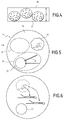
figure 4 is a view of hydrogel beads circulating in a channel of the microfluidic filtration unit; -
figure 5 is a view of an example of a droplet produced with the microfluidic system according to the invention; -
figure 6 is a view of the droplet offigure 5 after activation of the transcription. - A first
microfluidic system 10 comprising at least amicrofluidic filtration unit 12 according to the invention is shown infigure 1 . - The
microfluidic system 10 is for example for forming successive droplets 14 (shown infigures 4 and 5 ) of aninner fluid 16 dispersed in anouter fluid 18 immiscible with theinner fluid 16. By "immiscible" it is generally meant that less than 0.01 % of the inner fluid is able to solve in the second fluid at 25°C and ambient pressure. - In the example of
figure 5 , thedroplets 14 ofinner fluid 16 contain at least abiological entity 20, afirst medium 22 and asecond medium 24 which are loaded in the inner fluid before forming eachdroplet 14. - In the example of
figure 5 , thebiological entity 20 is a cell. Thefirst medium 22 is a lysis buffer and reverse transcriptase mix (enzyme and buffer). Thesecond medium 24 contains abead 25 of hydrogel, onto which markingoligonucleotides 26 are grafted. The oligonucleotides define a barcode unique to thebead 25 contained in thedroplet 14. - Preferably, at least 90% of the
droplets 14 formed in themicrofluidic system 10 contain onesingle cell 20, and onesingle bead 25. - In the present example, after being produced in the
microfluidic system 10, thesuccessive droplets 14 are submitted to a treatment, for example a photoactivated treatment such as a photocleavage, in order to cleave the biological entity and to release genetic material contained in the biological entity, such as mRNAs 27. As shown infigure 6 , theoligonucleotides 26 are able to be cleaved from thebeads 25 and to interact with the genetic material in order to produce a single cell barcoded cDNA in thedroplet 14. The cDNA can then be released from thedroplet 14 and analyzed by known means. - In reference to
figure 1 , themicrofluidic system 10 comprises at least asupport 30, in particular a chip, onto which a microfluidic pattern is formed. - The
support 30 carrying themicrofluidic system 10 is preferably made in one piece of a single material, in particular a polymeric material such as polydimethylsiloxane (PDMS) or polymethylmethacrylate (PMMA), polycarbonate (PC), epoxy, in particular photopolymerizable epoxy such as marketed by Norland Optical Adhesives (NOA) or glass. - A shown in
figure 1 , themicrofluidic system 10 comprises at least a workingchannel 32 emerging downstream into acollection outlet 34. The workingchannel 32 is for forming thesuccessive droplets 14. - The
microfluidic system 10 further comprises anupstream supply 36 ofinner fluid 16 advantageously containingbiological entities 20, anupstream supply 38 of first medium 22, and anintermediate supply 40 ofsecond medium 24. - The
microfluidic system 10 further comprises adownstream supply 42 ofouter fluid 18. - The working
channel 32 here extends linearly along an axis A-A' defining a working direction. Its maximum channel width is smaller than 250 micrometers and is comprised generally between 50 micrometers and 100 micrometers. - The
upstream supply 36 ofinner fluid 16 comprises asupply zone 50 connected to asource 52 ofinner fluid 16 containingbiological entities 20, anupstream filtering zone 54, acollection zone 56 located downstream of theupstream filtering zone 54, and at least adistribution canal 58 connecting thedistribution zone 56 to the workingchannel 32. - The
upstream filtering zone 54 is connected to thesupply zone 50 by severaldistinct distribution passages 60. Theupstream filtering zone 54 is for retaining the coarse particle and/or fiber contaminants potentially contained in theinner fluid 16. It comprises an enlarged filtering area fitted with a plurality ofpillars 62 delimiting between them sinuousintermediary passages 64. Thepillars 62 here have a polygonal cross section, in particular a diamond cross section. In a variant, thepillars 62 have a round cross section, in particular a circular cross section - In the example of
figure 1 , theupstream filtering zone 54 comprises at least twosuccessive lines 63 of staggeredpillars 62, the lines extending transversally to the axis A-A'. - The
collection zone 56 converges toward thedistribution canals 58. - In the example of
figure 1 , theupstream supply 36 comprises twoseparate distribution canals 58 surrounding the upstream firstmedium supply 38 and emerging into the workingchannel 32. - In this example, each
distribution canal 58 is connected upstream to thecollection zone 56. It delimits a zigzagfluidic resistor 66 forming a fluid resistor. - The
distribution canals 58 emerge into the workingchannel 32 at the same location, on opposite sides of the workingchannel 32. Eachdistribution canal 58 emerges at an angle comprised between 30° and 50° with the longitudinal axis A-A', in the direction of flow towards thecollection outlet 34. - The
upstream supply 38 of first medium 22 is connected to asource 70 offirst medium 22. It has generally the same structure as the upstreaminner fluid supply 36, with asupply zone 50, anupstream filtering zone 54, acollection zone 56, and adistribution canal 58, provided with afluidic resistor 66. It emerges axially in the workingchannel 32 at the same location as thedistribution canals 58 of theupstream supply 36 ofinner fluid 16. - As shown in
figure 2 , theintermediate supply 40 comprises asource 71 of second medium 24, asupply zone 50 connected to thesource 71, anupstream filtering zone 54, and acollection zone 56 located upstream of adistribution canal 58. - It further comprises an
intermediate filtering zone 80 comprising a plurality of parallelmicrofluidic filtration units 12 according to the invention, and a downstreamadditional filtering zone 82 located between theintermediate filtration zone 80 and the secondadditional filtering zone 82. - The
upstream filtering zone 54 is for retaining the coarse particle and/or fiber contaminants potentially contained in thesecond medium 24. - In the example of
figure 2 , thepillars 62 of theupstream filtering zone 54 of theintermediate supply 40 are "C shaped". - The
additional filtering zone 82 comprises a plurality of "S"-shape walls 84 delimiting between themnarrow filtering channels 86. - In reference to
figure 3 , eachmicrofluidic filtration unit 12 according to the invention comprises acentral channel 90 extending in a main direction parallel to an axis B-B', at least one and preferably twooutput channels 92, separate from thecentral channel 90, located on both sides of thecentral channel 90 and a plurality oflateral channels 94 connecting thecentral channel 90 to eachoutput channel 92. - The
central channel 90 has a taperinginlet portion 96, a linearcentral portion 98, connected to thelateral channels 94 and a dead-end portion 100 located at a downstream end of thecentral portion 98. - The width Ti of the
inlet portion 96 reduces towards thecentral portion 98 to create a funnel effect. - The length L1 of the
inlet portion 96, taken along axis B-B' is smaller than the length L2 of thecentral portion 98, taken along the same axis B-B'. The length L1 is generally comprised between 10% and 50% of the length L2 of thecentral portion 98. - The
central portion 98 has a constant cross-section taken perpendicular to axis B-B'. The width Tc of thecentral portion 98 is for example smaller than 100 micrometers and comprised between 30 micrometers and 70 micrometers. - The cross-section of the
central portion 98 is advantageously larger than the maximum cross-section of thebeads 25. - The dead-
end portion 100 is blind. It closes thecentral portion 98 at its downstream end. - The length L3 of the dead-
end portion 100, taken along axis B-B', is greater than the width Tc of thecentral portion 98. The length L3 of the dead-end portion 100 is preferably greater than twice the width Tc and is advantageously comprised between 3 times and 5 times the width Tc of thecentral portion 98. - In the example of
figure 3 , themicrofluidic filtration unit 12 comprises twolateral output channels 92 located on both sides of thecentral channel 90. Eachoutput channel 92 here extends parallel to axis B-B', apart from thecentral channel 98. - The
output channel 92 extends between a blindupstream end 110 located facing thecentral portion 98 of thecentral channel 90, in the vicinity of theinlet portion 96 and an opendownstream end 112, fluidly connected to thedistribution canal 58, through thesecond filtering zone 84 and thecollection zone 56. - In this example, the
downstream end 112 opens in the secondadditional filtering zone 82, upstream of thefiltering channel 86. - The width To of the
output channel 92 is equal to the width Tc of thecentral portion 98. - In the example of
figure 3 , themicrofiltration unit 12 comprises a plurality of longitudinally spaced apartlateral channels 94, located on both sides of thecentral portion 98 of thecentral channel 90. Eachlateral channel 94 emerges upstream in thecentral portion 98 of thecentral channel 90 and downstream in arespective output channel 92. - The number of
lateral channels 94 on each side of thecentral portion 98 is greater than 2, preferably greater than 5. - The
lateral channel 94 comprises at least anentrance portion 120 and anexit portion 122. - The
entrance portion 120 is connected to thecentral portion 98 and extends in a backward direction B. In the example offigure 3 , theexit portion 120 is connected to theoutput channel 92 and also extends in the backward direction B. - As shown in
figure 3 , the angle α between the backward direction B and the axis B-B' is less than 90°. - This angle is preferably comprised between 10° and 60°, more preferably between 20° and 50°.
- The "backward direction B" is here defined by the axis passing through the center of the
lateral channel 94 at its most backward position, here at theupstream opening 123A in thecentral channel 90 and the center of thelateral channel 94downstream opening 123B in theoutput channel 92. - In the example of
figure 3 , thelateral channel 94 has a generally "S" shape, with theentrance portion 120 forming a first curved portion towards thecentral channel 90 and theexit portion 122 forming a second curved portion towards theoutput channel 92. - The maximum width TI of the
lateral channel 94 is smaller than the width Tc of thecentral portion 98, and is preferably comprised between 80 % and 100 % of the width of thecentral portion 98 of thecentral channel 90. - Each
lateral channel 94 on one side of thecentral portion 98 is symmetrical with alateral channel 94 on the other side of thecentral portion 98. - The
lateral channels 94 on each side of thecentral portion 98 are longitudinally separated along the axis B-B' of thecentral portion 98. - The
lateral channels 94 do not overlap longitudinally. They are separated axially along the axis B-B', such that theupstream opening 123A of alateral channel 94 in thecentral channel 90 is located spaced apart and upstream of thedownstream opening 123B of an adjacent downstreamlateral channel 94, opening in theoutput channel 92. - The provision of a dead-
end portion 100 in thecentral channel 98, combined withlateral channels 94 extending backwards, efficiently retains the elements of the second medium 24 which need to be filtered, whereas thebeads 25 of the second medium can easily pass through thelateral channels 94. - In reference to
figure 1 , thedistribution canal 58 of theintermediate supply 40 of second medium 24 emerges in the workingchannel 32, downstream of thedistribution canal 58 of theupstream supply 36 ofinner fluid 16 and downstream of theupstream supply 38 offirst medium 22. - The
distribution canal 58 of theintermediate supply 40 extends in a tangential connecting direction C, the angle between the connecting direction C and the axis A-A' the workingchannel 32 being less than 45°. The outlet into the workingchannel 32 has an angle of preferably comprised between 30° and 35°, which further promotes the release of clogged items in that section of the channel into the larger channel. - The
downstream supply 42 ofouter fluid 18 is similar to theupstream supply 36. It comprises asource 130 ofouter fluid 18, connected to asupply zone 50. Thedownstream supply 42 further comprises anupstream filtering zone 54 and of acollection zone 56 which are analogous to respectively theupstream filtering zone 54, and thecollection zone 56 of theupstream supply 36. - The
downstream supply 42 ofouter fluid 18 comprises twoparallel distribution canals 58, havingfluidic resistors 66. Eachcanal 58 emerges transversely into the workingchannel 32, downstream of thedistribution canal 58 of theintermediate supply 40 ofsecond medium 24. - The operation of the
microfluidic system 10 according to the invention will be now described. - Initially, the
source 52 is connected to thesupply zone 50 to distributeinner fluid 16 containingbiological entities 20. Theinner fluid 16 flows through theupstream filtering zone 54, thecollection zone 56, and through thedistribution channels 58 to the workingchannel 32. - At the same time, the
source 70 of first medium 22 feeds thesupply zone 50 of the upstream firstmedium supply 38. The first medium 22 flows into theupstream filtering zone 54 and thecollection zone 56 to thedistribution canal 58 of theupstream supply 38. The first medium 22 mixes with theinner fluid 16 distributed in the workingchannel 32 at the same location. - The
source 71 of second medium 24 containinghydrogel beads 25 feeds thesupply zone 50 of theintermediate supply 40. The second medium 24 flows through thefirst filtering zone 54 and enters theparallel filtration units 12. - In each
filtration unit 12, thesecond medium 24 enters theinlet portion 96 and converges towards thecentral portion 98. It then flows through thecentral portion 98 downstream to the dead-end portion 100. - The impurities having a dimension greater than the channel width of the
lateral channels 94 remain trapped in thecentral portion 98, preferably in the dead-end portion 100. This is particularly the case for long impurities such as needle type materials. - On the contrary, the second medium 24 containing
beads 25 flows backwards through thelateral channels 94 and enters theoutput channels 92. - The second medium 24 then flows forwards into the
output channels 92 on both sides of thecentral channel 98 to thedownstream end 112. It then enters thesecond filtering zone 84, thecollection zone 56, and thedistribution canal 58 of theintermediate supply 40. The filteredsecond medium 24 is then added tangentially to the workingchannel 32, where it mixes with the flow ofinner fluid 16 containingbiological entities 20 andfirst medium 22. - The very efficient filtration in the
filtration zone 80, containing several parallelmicrofluidic filtration units 12 according to the invention, maintains substantially constant the ratio of the flow of the second medium 24 added to the workingchannel 32 to the flow of the mix ofinner fluid 16 containingbiological entities 20 and of first medium 22 in the working channel. This allows a very even distribution ofbeads 25 andbiological entities 20 in the workingchannel 32. - Then,
droplets 14 ofinner fluid 16 are formed by the transverse addition, in the workingchannel 32, of outer fluid 18 from thedownstream supply 42. Less than 20% of thedroplets 14, do not contain at least onebead 25. - The
droplets 14 are then recovered from thecollection outlet 34, and are activated as described before, in order to be analyzed. - The provision of a
microfluidic filter unit 12 is therefore very efficient to filter the impurities present in thesecond medium 24, without affecting the flow ofbeads 25. A very homogenous distribution ofbeads 25 is therefore obtained when thebeads 25 enter the workingchannel 32. - In an advantageous embodiment, shown in
figure 4 , the minimal channel width H2 of thelateral channel 94 in thefiltration unit 12, in particular the height H2 of thelateral channel 94 is greater than the average number diameter of thebeads 25. The minimal channel width H2 is generally comprised between 125% and 150% of the number average diameter of thebeads 25. - This surprisingly allows a better repartition of the
beads 25 and of thebiological entities 20 in thesuccessive droplets 14, and an increase in loading of thebeads 25 in thedroplets 14. - In a variant, the
inner fluid 16 contains aggregates/clumps of biological entities such as aggregates/clumps of cells. Eachdroplet 14 is loaded with at a least an aggregate/clump of biological entities, preferably only one aggregate/clump of biological entities.
Claims (15)
- A microfluidic filtration unit (12) comprising:- a central channel (90) extending in a main direction, the central channel (90) comprising an inlet portion (96), a central portion (98), and a dead-end portion (100) which is blind in the main direction,- at least a lateral channel (94) comprising an entrance portion (120) opening in the central portion (98) of the central channel (90), at least the entrance portion (120) of the lateral channel (94) extending in a backward direction, the angle between the main direction and the backward direction being less than 90°,- at least an output channel (92) separate from the central channel (90), the lateral channel (94) emerging in the output channel (92).
- A microfluidic filtration unit (12) according to claim 1, wherein the width of the central portion (98) is greater than the width of the lateral channel (94), preferably between 80% and 100 % of the width of the lateral channel (94).
- A microfluidic filtration unit (12) according to claim 1 or 2, wherein the length of the dead-end portion (100) in the main direction is greater than the width of the central portion (98), preferably between 200 % and 500 % of the width of the central portion (98).
- A microfluidic filtration unit (12) according to any one of the preceding claims, wherein the entrance portion (120) of the lateral channel (94) has a curved section.
- A microfluidic filtration unit (12) according to claim 4, wherein the lateral channel (94) has an "S" shape.
- A microfluidic filtration unit (12) according to any one of the preceding claims, comprising at least a set of lateral channels (94) comprising at least two lateral channels (94) distributed along a side of the central portion (98), each lateral channel (94) comprising an entrance portion (120), the central portion (98) of the central channel (90) opening in each entrance portion (120), at least the entrance portion (120) of each lateral channel (94) extending in a backward direction, the angle between the main direction and each backward direction being less than 90°.
- A microfluidic filtration unit (12) according to claim 6, the filtration unit (12) comprising at least two output channels (92), each lateral channel (94) of a set of lateral channels (94) opening in the same output channel (92), the output channels (92) preferably extending in the main direction.
- A microfluidic filtration unit (12) according to any one of claims 6 to 7, comprising at least two sets of lateral channels (94) distributed respectively on two sides of the central portion (98).
- A microfluidic filtration unit (12) according to any one of the preceding claims, comprising an inlet portion (96) having a funnel shape.
- A microfluidic system (10), comprising:- a supply zone (50) for introducing a fluid to be filtered, and a collection zone (56) for collecting a filtered fluid,- at least a filtration unit (12), advantageously a plurality of filtration units (12), according to any one of claims 1 to 9, the inlet portion (96) of the central channel (90) of each filtration unit (12) being in fluidic communication with the supply zone (50), each lateral channel (94) opening in an output channel (92), each output channel (92) being in fluidic communication with the collection zone (56).
- A microfluidic system (10) according to claim 10, comprising a working channel (32) extending in a working direction, preferably substantially perpendicular to the main direction, wherein the collection zone (54) is fluidly connected to the working channel (32) through a distribution canal (58) opening in the working channel (32), the distribution canal (58) extending in a connecting direction, the angle between the connecting direction and the working direction being less than 45°.
- A microfluidic system (10) according to any one of claims 10 or 11, comprising a source containing the fluid to be filtered, the fluid to be filtered comprising a plurality of particles intended to flow toward the collection zone (56) and the width of the lateral channel (94) being greater than the diameter of the particles, preferably being comprised between 1.01 and 1.99 times the diameter of the particles.
- Method for filtering a fluid comprising a medium and elongated impurities,- providing a microfluidic filtration unit (12) according to any one of claims 1 to 9,- passing the fluid in the central channel (90),- flowing the medium in the backwards direction in the at least one lateral channel (94),- retaining elongated impurities in the blind lumen of the dead-end portion (100).
- Method according to claim 13, further comprising a step of dispensing the medium (24) in an inner fluid (16), and dispersing the inner fluid (16) containing the medium (24) in an outer fluid (18) to form droplets (14) of inner fluid (16) containing the medium (24) in the outer fluid (18).
- Method according to claim 14, wherein the medium comprises beads (25), in particular hydrogel beads (25), the inner fluid (16) comprising biological entities (20), in particular cells and/or clumps/aggregates of cells, the formation of the droplets (14) comprising the encapsulation of at least one biological entity (20) and of at least one bead (25) in each of several successive droplets (14).
Priority Applications (1)
| Application Number | Priority Date | Filing Date | Title |
|---|---|---|---|
| EP16305751.6A EP3260201A1 (en) | 2016-06-21 | 2016-06-21 | Microfluidic filtration unit and related microfluidic system |
Applications Claiming Priority (1)
| Application Number | Priority Date | Filing Date | Title |
|---|---|---|---|
| EP16305751.6A EP3260201A1 (en) | 2016-06-21 | 2016-06-21 | Microfluidic filtration unit and related microfluidic system |
Publications (1)
| Publication Number | Publication Date |
|---|---|
| EP3260201A1 true EP3260201A1 (en) | 2017-12-27 |
Family
ID=56360342
Family Applications (1)
| Application Number | Title | Priority Date | Filing Date |
|---|---|---|---|
| EP16305751.6A Withdrawn EP3260201A1 (en) | 2016-06-21 | 2016-06-21 | Microfluidic filtration unit and related microfluidic system |
Country Status (1)
| Country | Link |
|---|---|
| EP (1) | EP3260201A1 (en) |
Cited By (1)
| Publication number | Priority date | Publication date | Assignee | Title |
|---|---|---|---|---|
| EP4434627A1 (en) * | 2023-03-24 | 2024-09-25 | Ecole Polytechnique Federale De Lausanne (Epfl) | Device and method for producing a combinatorial microcompartment within a carrier phase |
Citations (4)
| Publication number | Priority date | Publication date | Assignee | Title |
|---|---|---|---|---|
| US20080233607A1 (en) * | 2004-11-11 | 2008-09-25 | Hanry Yu | Cell Culture Device |
| US20140375991A1 (en) * | 2012-03-01 | 2014-12-25 | Schlumberger Technology Corporation | Method and Apparatus for Determining Asphaltene Yield and Flocculation Point of Crude Oil |
| EP2818542A1 (en) * | 2012-01-05 | 2014-12-31 | Hitachi Chemical Company, Ltd. | Cell trapping device |
| WO2015164212A1 (en) | 2014-04-21 | 2015-10-29 | President And Fellows Of Harvard College | Systems and methods for barcoding nucleic acids |
-
2016
- 2016-06-21 EP EP16305751.6A patent/EP3260201A1/en not_active Withdrawn
Patent Citations (4)
| Publication number | Priority date | Publication date | Assignee | Title |
|---|---|---|---|---|
| US20080233607A1 (en) * | 2004-11-11 | 2008-09-25 | Hanry Yu | Cell Culture Device |
| EP2818542A1 (en) * | 2012-01-05 | 2014-12-31 | Hitachi Chemical Company, Ltd. | Cell trapping device |
| US20140375991A1 (en) * | 2012-03-01 | 2014-12-25 | Schlumberger Technology Corporation | Method and Apparatus for Determining Asphaltene Yield and Flocculation Point of Crude Oil |
| WO2015164212A1 (en) | 2014-04-21 | 2015-10-29 | President And Fellows Of Harvard College | Systems and methods for barcoding nucleic acids |
Cited By (2)
| Publication number | Priority date | Publication date | Assignee | Title |
|---|---|---|---|---|
| EP4434627A1 (en) * | 2023-03-24 | 2024-09-25 | Ecole Polytechnique Federale De Lausanne (Epfl) | Device and method for producing a combinatorial microcompartment within a carrier phase |
| WO2024200381A1 (en) * | 2023-03-24 | 2024-10-03 | Ecole polytechnique fédérale de Lausanne (EPFL) | Device and method for producing a combinatorial microcompartment within a carrier phase |
Similar Documents
| Publication | Publication Date | Title |
|---|---|---|
| US10941393B2 (en) | Microfluidic droplet encapsulation | |
| US11123733B2 (en) | Inertial droplet generation and particle encapsulation | |
| EP1682438B1 (en) | Multilayer hydrodynamic sheath flow structure | |
| EP2573540A1 (en) | Fluid controlling apparatus and filter and biochip including the fluid controlling apparatus | |
| EP3263693A1 (en) | Method for separating cells, and device therefor | |
| KR100942184B1 (en) | Microcapsule manufacturing apparatus and method | |
| CN101102847A (en) | Cell separation using microchannel having patterned posts | |
| KR20220119432A (en) | Microfluidic device and method of use thereof | |
| EP3260201A1 (en) | Microfluidic filtration unit and related microfluidic system | |
| EP2639040B1 (en) | Gel reduction device and gel reduction method | |
| KR101666425B1 (en) | A Micro-Channel Reactor | |
| EP1448798A1 (en) | Nanostructure, in particular for analysing individual molecules | |
| US20230347345A1 (en) | Spiral inertial microfluidic devices and methods to remove contaminants | |
| US11833511B2 (en) | Microfluidic devices with multiple inlets and outlets | |
| DE102018220898A1 (en) | Microfluidic device and method for filtering a fluid | |
| DE10318864B3 (en) | Micro-fluidic valve, for controlled introduction of fluid into channel during capillary electrophoresis, combines electrical potential gradient with curvature inducing Coanda effect | |
| WO2025034894A1 (en) | Devices and methods for isolation of biological entities in suspension | |
| DE102021214281A1 (en) | Device and method for splitting three-dimensional agglomerates | |
| AU2011205167B2 (en) | Multilayer hydrodynamic sheath flow structure | |
| Tran | Deterministic Lateral Displacement for Cell Sorting | |
| WO2023211901A1 (en) | Spiral inertial microfluidic devices and methods to remove contaminants |
Legal Events
| Date | Code | Title | Description |
|---|---|---|---|
| PUAI | Public reference made under article 153(3) epc to a published international application that has entered the european phase |
Free format text: ORIGINAL CODE: 0009012 |
|
| AK | Designated contracting states |
Kind code of ref document: A1 Designated state(s): AL AT BE BG CH CY CZ DE DK EE ES FI FR GB GR HR HU IE IS IT LI LT LU LV MC MK MT NL NO PL PT RO RS SE SI SK SM TR |
|
| AX | Request for extension of the european patent |
Extension state: BA ME |
|
| STAA | Information on the status of an ep patent application or granted ep patent |
Free format text: STATUS: THE APPLICATION IS DEEMED TO BE WITHDRAWN |
|
| 18D | Application deemed to be withdrawn |
Effective date: 20180628 |