EP3260018B1 - Power supply system for shelving system - Google Patents
Power supply system for shelving system Download PDFInfo
- Publication number
- EP3260018B1 EP3260018B1 EP17176450.9A EP17176450A EP3260018B1 EP 3260018 B1 EP3260018 B1 EP 3260018B1 EP 17176450 A EP17176450 A EP 17176450A EP 3260018 B1 EP3260018 B1 EP 3260018B1
- Authority
- EP
- European Patent Office
- Prior art keywords
- protection cover
- circuit board
- mounting plate
- mounting hole
- power supply
- Prior art date
- Legal status (The legal status is an assumption and is not a legal conclusion. Google has not performed a legal analysis and makes no representation as to the accuracy of the status listed.)
- Active
Links
Images



Classifications
-
- A—HUMAN NECESSITIES
- A47—FURNITURE; DOMESTIC ARTICLES OR APPLIANCES; COFFEE MILLS; SPICE MILLS; SUCTION CLEANERS IN GENERAL
- A47F—SPECIAL FURNITURE, FITTINGS, OR ACCESSORIES FOR SHOPS, STOREHOUSES, BARS, RESTAURANTS OR THE LIKE; PAYING COUNTERS
- A47F5/00—Show stands, hangers, or shelves characterised by their constructional features
- A47F5/10—Adjustable or foldable or dismountable display stands
- A47F5/101—Display racks with slotted uprights
- A47F5/103—Display shelving racks with the uprights aligned in only one plane
-
- F—MECHANICAL ENGINEERING; LIGHTING; HEATING; WEAPONS; BLASTING
- F21—LIGHTING
- F21S—NON-PORTABLE LIGHTING DEVICES; SYSTEMS THEREOF; VEHICLE LIGHTING DEVICES SPECIALLY ADAPTED FOR VEHICLE EXTERIORS
- F21S8/00—Lighting devices intended for fixed installation
-
- H—ELECTRICITY
- H05—ELECTRIC TECHNIQUES NOT OTHERWISE PROVIDED FOR
- H05K—PRINTED CIRCUITS; CASINGS OR CONSTRUCTIONAL DETAILS OF ELECTRIC APPARATUS; MANUFACTURE OF ASSEMBLAGES OF ELECTRICAL COMPONENTS
- H05K7/00—Constructional details common to different types of electric apparatus
- H05K7/14—Mounting supporting structure in casing or on frame or rack
- H05K7/1422—Printed circuit boards receptacles, e.g. stacked structures, electronic circuit modules or box like frames
-
- A—HUMAN NECESSITIES
- A47—FURNITURE; DOMESTIC ARTICLES OR APPLIANCES; COFFEE MILLS; SPICE MILLS; SUCTION CLEANERS IN GENERAL
- A47B—TABLES; DESKS; OFFICE FURNITURE; CABINETS; DRAWERS; GENERAL DETAILS OF FURNITURE
- A47B96/00—Details of cabinets, racks or shelf units not covered by a single one of groups A47B43/00 - A47B95/00; General details of furniture
- A47B96/06—Brackets or similar supporting means for cabinets, racks or shelves
- A47B96/061—Cantilever brackets
-
- A—HUMAN NECESSITIES
- A47—FURNITURE; DOMESTIC ARTICLES OR APPLIANCES; COFFEE MILLS; SPICE MILLS; SUCTION CLEANERS IN GENERAL
- A47B—TABLES; DESKS; OFFICE FURNITURE; CABINETS; DRAWERS; GENERAL DETAILS OF FURNITURE
- A47B97/00—Furniture or accessories for furniture, not provided for in other groups of this subclass
-
- A—HUMAN NECESSITIES
- A47—FURNITURE; DOMESTIC ARTICLES OR APPLIANCES; COFFEE MILLS; SPICE MILLS; SUCTION CLEANERS IN GENERAL
- A47F—SPECIAL FURNITURE, FITTINGS, OR ACCESSORIES FOR SHOPS, STOREHOUSES, BARS, RESTAURANTS OR THE LIKE; PAYING COUNTERS
- A47F11/00—Arrangements in shop windows, shop floors or show cases
- A47F11/06—Means for bringing about special optical effects
- A47F11/10—Arrangements of light sources
-
- F—MECHANICAL ENGINEERING; LIGHTING; HEATING; WEAPONS; BLASTING
- F21—LIGHTING
- F21V—FUNCTIONAL FEATURES OR DETAILS OF LIGHTING DEVICES OR SYSTEMS THEREOF; STRUCTURAL COMBINATIONS OF LIGHTING DEVICES WITH OTHER ARTICLES, NOT OTHERWISE PROVIDED FOR
- F21V17/00—Fastening of component parts of lighting devices, e.g. shades, globes, refractors, reflectors, filters, screens, grids or protective cages
- F21V17/10—Fastening of component parts of lighting devices, e.g. shades, globes, refractors, reflectors, filters, screens, grids or protective cages characterised by specific fastening means or way of fastening
- F21V17/104—Fastening of component parts of lighting devices, e.g. shades, globes, refractors, reflectors, filters, screens, grids or protective cages characterised by specific fastening means or way of fastening using feather joints, e.g. tongues and grooves, with or without friction
-
- F—MECHANICAL ENGINEERING; LIGHTING; HEATING; WEAPONS; BLASTING
- F21—LIGHTING
- F21V—FUNCTIONAL FEATURES OR DETAILS OF LIGHTING DEVICES OR SYSTEMS THEREOF; STRUCTURAL COMBINATIONS OF LIGHTING DEVICES WITH OTHER ARTICLES, NOT OTHERWISE PROVIDED FOR
- F21V23/00—Arrangement of electric circuit elements in or on lighting devices
-
- F—MECHANICAL ENGINEERING; LIGHTING; HEATING; WEAPONS; BLASTING
- F21—LIGHTING
- F21V—FUNCTIONAL FEATURES OR DETAILS OF LIGHTING DEVICES OR SYSTEMS THEREOF; STRUCTURAL COMBINATIONS OF LIGHTING DEVICES WITH OTHER ARTICLES, NOT OTHERWISE PROVIDED FOR
- F21V33/00—Structural combinations of lighting devices with other articles, not otherwise provided for
-
- H—ELECTRICITY
- H05—ELECTRIC TECHNIQUES NOT OTHERWISE PROVIDED FOR
- H05K—PRINTED CIRCUITS; CASINGS OR CONSTRUCTIONAL DETAILS OF ELECTRIC APPARATUS; MANUFACTURE OF ASSEMBLAGES OF ELECTRICAL COMPONENTS
- H05K1/00—Printed circuits
- H05K1/02—Details
-
- A—HUMAN NECESSITIES
- A47—FURNITURE; DOMESTIC ARTICLES OR APPLIANCES; COFFEE MILLS; SPICE MILLS; SUCTION CLEANERS IN GENERAL
- A47B—TABLES; DESKS; OFFICE FURNITURE; CABINETS; DRAWERS; GENERAL DETAILS OF FURNITURE
- A47B2220/00—General furniture construction, e.g. fittings
- A47B2220/0075—Lighting
- A47B2220/0077—Lighting for furniture, e.g. cupboards and racks
-
- A—HUMAN NECESSITIES
- A47—FURNITURE; DOMESTIC ARTICLES OR APPLIANCES; COFFEE MILLS; SPICE MILLS; SUCTION CLEANERS IN GENERAL
- A47B—TABLES; DESKS; OFFICE FURNITURE; CABINETS; DRAWERS; GENERAL DETAILS OF FURNITURE
- A47B57/00—Cabinets, racks or shelf units, characterised by features for adjusting shelves or partitions
- A47B57/30—Cabinets, racks or shelf units, characterised by features for adjusting shelves or partitions with means for adjusting the height of detachable shelf supports
- A47B57/40—Cabinets, racks or shelf units, characterised by features for adjusting shelves or partitions with means for adjusting the height of detachable shelf supports consisting of hooks coacting with openings
-
- A—HUMAN NECESSITIES
- A47—FURNITURE; DOMESTIC ARTICLES OR APPLIANCES; COFFEE MILLS; SPICE MILLS; SUCTION CLEANERS IN GENERAL
- A47F—SPECIAL FURNITURE, FITTINGS, OR ACCESSORIES FOR SHOPS, STOREHOUSES, BARS, RESTAURANTS OR THE LIKE; PAYING COUNTERS
- A47F5/00—Show stands, hangers, or shelves characterised by their constructional features
- A47F5/10—Adjustable or foldable or dismountable display stands
-
- F—MECHANICAL ENGINEERING; LIGHTING; HEATING; WEAPONS; BLASTING
- F21—LIGHTING
- F21V—FUNCTIONAL FEATURES OR DETAILS OF LIGHTING DEVICES OR SYSTEMS THEREOF; STRUCTURAL COMBINATIONS OF LIGHTING DEVICES WITH OTHER ARTICLES, NOT OTHERWISE PROVIDED FOR
- F21V23/00—Arrangement of electric circuit elements in or on lighting devices
- F21V23/02—Arrangement of electric circuit elements in or on lighting devices the elements being transformers, impedances or power supply units, e.g. a transformer with a rectifier
-
- H—ELECTRICITY
- H01—ELECTRIC ELEMENTS
- H01R—ELECTRICALLY-CONDUCTIVE CONNECTIONS; STRUCTURAL ASSOCIATIONS OF A PLURALITY OF MUTUALLY-INSULATED ELECTRICAL CONNECTING ELEMENTS; COUPLING DEVICES; CURRENT COLLECTORS
- H01R13/00—Details of coupling devices of the kinds covered by groups H01R12/70 or H01R24/00 - H01R33/00
- H01R13/02—Contact members
- H01R13/22—Contacts for co-operating by abutting
- H01R13/24—Contacts for co-operating by abutting resilient; resiliently-mounted
- H01R13/2464—Contacts for co-operating by abutting resilient; resiliently-mounted characterized by the contact point
- H01R13/2478—Contacts for co-operating by abutting resilient; resiliently-mounted characterized by the contact point spherical
-
- H—ELECTRICITY
- H01—ELECTRIC ELEMENTS
- H01R—ELECTRICALLY-CONDUCTIVE CONNECTIONS; STRUCTURAL ASSOCIATIONS OF A PLURALITY OF MUTUALLY-INSULATED ELECTRICAL CONNECTING ELEMENTS; COUPLING DEVICES; CURRENT COLLECTORS
- H01R25/00—Coupling parts adapted for simultaneous co-operation with two or more identical counterparts, e.g. for distributing energy to two or more circuits
- H01R25/14—Rails or bus-bars constructed so that the counterparts can be connected thereto at any point along their length
- H01R25/142—Their counterparts
Definitions
- the present application relates to lighting equipments, and more particularly to a power supply system for shelving system.
- LED Light emitting diode
- incandescent lighting and fluorescent lighting Recently, a number of LED lighting apparatuses have been designed to replace the halogen apparatus, as well as other traditional incandescent or fluorescence lighting apparatuses. LED lightings also are used to shelf track lighting device. Shelves are used in very wide range, such as in shopping malls, logistics warehouses, factory warehouses, etc., which need shelves to place goods. For these shelves, lighting is necessary, especially in the mall, it has particularly high requirements of lighting, such as saving space, security, easy assembly, beautiful, and so on.
- a power source for supplying electric power to the LED lighting mounted on the shelf irradiation surface is generally provided on the back of the shelf. Therefore, it is need to pass through wires from the shelf irradiation surface to the back of the shelf so as to electrically connect the LED lighting with the power source supply.
- the shelves are required to have a strong versatility to be able to place different kinds of goods, it is necessary to set different mounting position of the shelf boards, such as removing it or replacing it.
- a patent application whose Chinese application number is CN 201520163602.9 , and title is a power supply system for shelf track lighting device, publics a shelves for solving the above problems.
- the ejection plug provided on the support arm of the shelves protrudes from the side of the support arm.
- the components including vertical rails, backboards, or the like, have very small tolerance.
- US 6 527 565 B1 relates to an adjustable light display assembly in which the light is adjustable in a manner of a track light with the support for the light capable of assuming many configurations including wall panels, support stands and multiple light fixtures.
- the shelving system include a plurality of vertical shelf rails 10, a lot of backboards 20 disposed between the two vertical shelf rails 10, a plurality of power supply system 100 suspending on the vertical shelf rails 10, and a plurality of bus bars 40 disposed in the vertical shelf rails 10.
- the shelving system further includes some carrier elements, wires, and LED lightings mounted on the carrier elements, which are well known for a person skilled in the art and not described in detail.
- Each of the vertical shelf rails 10 is made of metal material and is a hollow rail having a rectangle cross-section.
- the vertical shelf rail 10 includes a plurality of punched holes 11, and a locating protrudes 12 provided on one side wall of the punched holes 11.
- the punched holes 11 have a rectangle shape and are opened along an extending direction of the vertical shelf rail 10 and spaced apart from each other.
- the locating protrudes 12 are disposed on a side wall of the punched holes 11 which is perpendicular to the extending direction of the vertical shelf rail 10.
- two protrudes 12 are provided respectively two side walls of the vertical shelf rail 10 which are perpendicular to the extending direction thereof.
- the backboards 20 may be made of sheet metal and includes a plurality of catching hooks 21.
- the catching hooks 21 are perpendicular to the body of the backboard 20.
- Each of the catching hooks 21 includes an arm for clamping the side wall of the punched holes 11, that is, which is perpendicular to the extending direction of the vertical shelf rail 10.
- the power supply system 30 includes a support arm 31, and an electrical supply device 32 mounted on the support arm 31.
- the support arm 31 is used to place the parts, such as carrier elements.
- One end of the power supply system 30 is clamped into one of the punched holes 11 of the vertical shelf rail 10.
- a number of hooks (not labeled) are provided on the one end of the support arm 31.
- the pluralities of the hooks are caught respectively in the different punched holes 11, thereby holding the support arm 31 in the vertical shelf rail 10 using the lever principle and the gravitational force of the carrier elements.
- the assembling method of the support arm 31 is well known for a person skilled in the art and not described in detail.
- the support arm 31 includes a mounting hole 311, and a mounting plate 312 provided in the mounting hole 311.
- the mounting hole 311 is opened an end of the support arm 31 which is inserted into the punched hole 11 so as to electrically connected the electrical supply device 32 to the bus bar 40.
- the mounting hole 311 has a same or similar configuration with electrical supply device 32 so as to accommodate the electrical supply device 32 therein.
- the mounting plate 312 is disposed in the mounting hole 311 and has less thickness than the mounting hole 311.
- the mounting plate 312 may be formed by milling the mounting hole 311 or by welding a metal plate. In the present embodiment, the mounting plate 312 is formed by welding for reducing cost.
- One side of the mounting plate 312 is flush with one side of the mounting hole 311 to form a groove for placing the electrical supply device 32.
- Two hollow holes 313 at both ends of the mounting plate 312 is provided between the mounting hole 311 and the mounting plate 312 and is configured for assembling the electrical supply device 22. The specific assembly principle thereof will be described below.
- the electrical supply device 32 is mounted on the mounting plate 312 and includes a circuit board 321, a positive electrical contact 322 disposed on the circuit board 321, a negative electrical contact 323 disposed on the circuit board 321, a first protection cover 324 covering one side of the circuit board 321, a second protection cover 325 covering the other side of the circuit board 321, and a chip socket 326 disposed on the circuit board 321.
- the circuit board 321 provides two wires thereon, and the two wires are electrically connected to the positive and negative electrical contacts 322, 323 respectively.
- the wires provided on the circuit board 321 can provide voltage, such as 110V or 220V, which is appropriate for small power appliances, such as LED lighting.
- the positive and negative electrical contacts 322, 323 have the same structure and operating principle, with only positive and negative.
- the positive and negative electrical contacts 322, 323 are electrically connected to the positive and negative poles of the bus bar 40 to achieve the purpose of electrically connection.
- the positive and negative electrical contacts 322, 323 are a push-in resilient ball head plunger.
- the push-in resilient ball head plunger is a standard part of the prior art and includes a semi-closed cylinder, a ball, and a spring sandwiched between the semi-closed cylinder and the ball.
- the diameter of the ball is larger than that of the mouth of the semi-closed cylinder so that the portion of the ball may be exposed to the mouth of the semi-closed cylinder and retracted in the semi-closed cylinder under the pressure of the external force.
- a first and second through holes 3241, 3242 are provided on the first protection cover 324 and are configured for extending the positive and negative electrical contacts 322, 323 out of therefrom so as to electrically connected with the bus bar 40. As there is the first protection cover 324, the circuit board 321 is clamped between the mounting plate 312 and the first protection cover 324 so as to protect the circuit board 321.
- the sum of the thicknesses of the circuit board 321 and the first protection cover 324 is equal to the difference between the depth of the mounting hole 311 and the thickness of the mounting plate 312. Therefore, the side wall of the first protection cover 324 opposite to the circuit board 321 is flush with that of the mounting hole 311. It is of course understood that there are many ways in which the side walls of the first protection cover 324 opposite to the circuit board 321 are flush with the side walls of the mounting holes 311. In the present embodiment, it is only an embodiment.
- the assembling methods of the first protection cover 324 may have many, such as Welded, caulked, or fastened to the mounting plate 312 using fasteners. In the present embodiment, the first protection cover 324 is coupled to the second protection cover 325.
- the primary purpose of the second protection cover 325 is to protect the back of the positive and negative electrical contacts 322, 323. Since an axial length of the positive and negative electrical contacts 322, 323 is larger than the sum of the thickness of the circuit board 321 and the first protection cover 324, ends of the positive and negative electrical contacts 322, 323 pass through the hollow holes 313 respectively. Therefore, it is need the second protection cover 325 to protect the positive and negative electrical contacts 322, 323 from short circuit. It may be understood that if the positive and negative electrical contacts 322, 323 are protected by other means, such as using a glue filling method, the second protection cover 325 may not be used.
- the second protection cover 325 is also provided with a plurality of methods such as welding, riveting, or fastening on the mounting plate 312 using fasteners.
- the first protection cover 324 provides at least two pins 3243
- the second protection cover 325 provides at least two holes 3251.
- the at least two pins 3243 pass through the hollow holes 313 and are inserted into the holes 3251 so as to fix the relative position of the first and second protection covers 324, 325.
- the first and second protection covers 324, 325 respectively have 5 pins 3243 and 5 holes 3251.
- the 5 pins 3243 and 5 holes 3251 are respectively distributed at different positions of the first and second protective covers 324, 325.
- the pins 3243 are in interference fit with the holes 3251. Therefore, the pins 3243 can be inserted into the holes 3251 directly, which make assembly easier.
- the chip socket 326 is also a standard member known to these skilled in the art and is used to electrically connect to the circuit board 321 for electrically connecting with a plug of LED lighting.
- the bus bar 40 is received in the vertical shelf rail 10 and includes two current conductors 41 spaced apart and insulated from each other. Further, the two current conductors 41 are arranged vertically so that the two current conductors 41 are arranged along the axial direction of the vertical shelf rail 10. As a result, the vertical shelf rail 10 can supply power to the electrical supply device 32 at an arbitrary position.
- the current conductors 41 is made of copper and are tiled on the same PCB (Printed Circuit Board) to be able to power LED lightings.
- the support arm 30 When the support arm 30 is inserted into the punched hole 11 and the positive and negative electrical contacts 322, 323 are electrically connected to the two current conductors 41 of the bus bar 40 so as to achieve the purpose of electrical connection.
- the assembly of the support arm 30 can be completed without being affected by the electrical supply device 32 as long as the end of the support art 30 can be inserted into the punched hole 11 as the side wall of the first protection cover 324 opposite to the circuit board 321 is flush with the side wall of the mounting hole 311, that is, flush with the side wall of the support arm 30.
- the effect caused by the tolerance and fit is reduced to a minimum value when the vertical shelf rail 10, backboard 20, and the support arm 30 are assembled.
Landscapes
- Engineering & Computer Science (AREA)
- General Engineering & Computer Science (AREA)
- Microelectronics & Electronic Packaging (AREA)
- Arrangement Of Elements, Cooling, Sealing, Or The Like Of Lighting Devices (AREA)
- Casings For Electric Apparatus (AREA)
- Non-Portable Lighting Devices Or Systems Thereof (AREA)
Description
- This present application claims benefit of the Chinese Application,
CN201610470525.0, filed on June 22, 2016 - The present application relates to lighting equipments, and more particularly to a power supply system for shelving system.
- Light emitting diode (LED) is growing in popularity due to decreasing costs and long life compared to incandescent lighting and fluorescent lighting. Recently, a number of LED lighting apparatuses have been designed to replace the halogen apparatus, as well as other traditional incandescent or fluorescence lighting apparatuses. LED lightings also are used to shelf track lighting device. Shelves are used in very wide range, such as in shopping malls, logistics warehouses, factory warehouses, etc., which need shelves to place goods. For these shelves, lighting is necessary, especially in the mall, it has particularly high requirements of lighting, such as saving space, security, easy assembly, beautiful, and so on.
- In the prior art, a power source for supplying electric power to the LED lighting mounted on the shelf irradiation surface is generally provided on the back of the shelf. Therefore, it is need to pass through wires from the shelf irradiation surface to the back of the shelf so as to electrically connect the LED lighting with the power source supply. On one hand, it is inconvenient to arrange the wires and has more and messy wires due to the above power supply method. As a result, it is not advantageous for maintenance and aesthetics. On the other hand, as the shelves are required to have a strong versatility to be able to place different kinds of goods, it is necessary to set different mounting position of the shelf boards, such as removing it or replacing it. A patent application, whose Chinese application number is
CN 201520163602.9
US 6 527 565 B1 relates to an adjustable light display assembly in which the light is adjustable in a manner of a track light with the support for the light capable of assuming many configurations including wall panels, support stands and multiple light fixtures. - Therefore, it is necessary to provide a power supply system for shelving system which makes it possible to solve the above problems.
- Many aspects of the embodiments can be better understood with references to the following drawings. The components in the drawings are not necessarily drawn to scale, the emphasis instead being placed upon clearly illustrating the principles of the embodiments. Moreover, in the drawings, like reference numerals designate corresponding parts throughout two views.
-
FIG. 1 is an exploded view of a power supply system for shelving system according to an embodiment. -
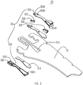
FIG. 2 is an exploded view of the power supply system ofFIG. 1 . -
FIG. 3 is a cross section view of the power supply system ofFIG. 2 . -
FIG. 4 is a schematic view of a support arm of the power supply system for shelving system ofFIG. 1 . - The present application is illustrated by way of example and not by way of limitation in the figures of the accompanying drawings. It should be noted that references to "an" or "one" embodiment in this application are not necessarily to the same embodiment, and such references mean at least one.
- Referring to
FIG. 1 to FIG. 3 , apower supply system 100 for shelving system according to an embodiment is shown. The shelving system include a plurality of vertical shelf rails 10, a lot ofbackboards 20 disposed between the two vertical shelf rails 10, a plurality ofpower supply system 100 suspending on the vertical shelf rails 10, and a plurality ofbus bars 40 disposed in the vertical shelf rails 10. It can be understood that the shelving system further includes some carrier elements, wires, and LED lightings mounted on the carrier elements, which are well known for a person skilled in the art and not described in detail. - Each of the vertical shelf rails 10 is made of metal material and is a hollow rail having a rectangle cross-section. The vertical shelf rail 10 includes a plurality of punched holes 11, and a locating
protrudes 12 provided on one side wall of the punched holes 11. The punched holes 11 have a rectangle shape and are opened along an extending direction of the vertical shelf rail 10 and spaced apart from each other. The locatingprotrudes 12 are disposed on a side wall of the punched holes 11 which is perpendicular to the extending direction of the vertical shelf rail 10. In order to make the vertical shelf rail 10 facilitate to use and no need to distinguish the upper and lower of the vertical shelf rail 10, twoprotrudes 12 are provided respectively two side walls of the vertical shelf rail 10 which are perpendicular to the extending direction thereof. - The
backboards 20 may be made of sheet metal and includes a plurality of catchinghooks 21. Thecatching hooks 21 are perpendicular to the body of thebackboard 20. Each of thecatching hooks 21 includes an arm for clamping the side wall of the punched holes 11, that is, which is perpendicular to the extending direction of the vertical shelf rail 10. When one of the pluralities ofbackboards 20 is mounted two vertical shelf rails 10 which are spaced apart from each other, the relative position of thebackboard 20 and the vertical shelf rail 10 can be fixed. - The
power supply system 30 includes asupport arm 31, and anelectrical supply device 32 mounted on thesupport arm 31. Thesupport arm 31 is used to place the parts, such as carrier elements. One end of thepower supply system 30 is clamped into one of the punched holes 11 of the vertical shelf rail 10. In order to make one end of thesupport arm 31 tightly hold into the punched hole 11, a number of hooks (not labeled) are provided on the one end of thesupport arm 31. The pluralities of the hooks are caught respectively in the different punched holes 11, thereby holding thesupport arm 31 in the vertical shelf rail 10 using the lever principle and the gravitational force of the carrier elements. The assembling method of thesupport arm 31 is well known for a person skilled in the art and not described in detail. Thesupport arm 31 includes amounting hole 311, and amounting plate 312 provided in themounting hole 311. Themounting hole 311 is opened an end of thesupport arm 31 which is inserted into the punched hole 11 so as to electrically connected theelectrical supply device 32 to thebus bar 40. Themounting hole 311 has a same or similar configuration withelectrical supply device 32 so as to accommodate theelectrical supply device 32 therein. Themounting plate 312 is disposed in themounting hole 311 and has less thickness than themounting hole 311. Themounting plate 312 may be formed by milling themounting hole 311 or by welding a metal plate. In the present embodiment, themounting plate 312 is formed by welding for reducing cost. One side of themounting plate 312 is flush with one side of themounting hole 311 to form a groove for placing theelectrical supply device 32. Twohollow holes 313 at both ends of themounting plate 312 is provided between themounting hole 311 and themounting plate 312 and is configured for assembling the electrical supply device 22. The specific assembly principle thereof will be described below. - The
electrical supply device 32 is mounted on themounting plate 312 and includes acircuit board 321, a positiveelectrical contact 322 disposed on thecircuit board 321, a negativeelectrical contact 323 disposed on thecircuit board 321, afirst protection cover 324 covering one side of thecircuit board 321, asecond protection cover 325 covering the other side of thecircuit board 321, and achip socket 326 disposed on thecircuit board 321. Thecircuit board 321 provides two wires thereon, and the two wires are electrically connected to the positive and negativeelectrical contacts circuit board 321 can provide voltage, such as 110V or 220V, which is appropriate for small power appliances, such as LED lighting. The positive and negativeelectrical contacts electrical contacts bus bar 40 to achieve the purpose of electrically connection. In order to fit closely the positive and negativeelectrical contacts bus bar 40 and avoid false connection from causing the LED lamp to be powered abnormally, the positive and negativeelectrical contacts holes first protection cover 324 and are configured for extending the positive and negativeelectrical contacts bus bar 40. As there is thefirst protection cover 324, thecircuit board 321 is clamped between the mountingplate 312 and thefirst protection cover 324 so as to protect thecircuit board 321. The sum of the thicknesses of thecircuit board 321 and thefirst protection cover 324 is equal to the difference between the depth of the mountinghole 311 and the thickness of the mountingplate 312. Therefore, the side wall of thefirst protection cover 324 opposite to thecircuit board 321 is flush with that of the mountinghole 311. It is of course understood that there are many ways in which the side walls of thefirst protection cover 324 opposite to thecircuit board 321 are flush with the side walls of the mounting holes 311. In the present embodiment, it is only an embodiment. The assembling methods of thefirst protection cover 324 may have many, such as Welded, caulked, or fastened to the mountingplate 312 using fasteners. In the present embodiment, thefirst protection cover 324 is coupled to thesecond protection cover 325. The primary purpose of thesecond protection cover 325 is to protect the back of the positive and negativeelectrical contacts electrical contacts circuit board 321 and thefirst protection cover 324, ends of the positive and negativeelectrical contacts hollow holes 313 respectively. Therefore, it is need thesecond protection cover 325 to protect the positive and negativeelectrical contacts electrical contacts second protection cover 325 may not be used. Thesecond protection cover 325 is also provided with a plurality of methods such as welding, riveting, or fastening on the mountingplate 312 using fasteners. However, in the present embodiment, thefirst protection cover 324 provides at least two pins 3243, and thesecond protection cover 325 provides at least twoholes 3251. The at least two pins 3243 pass through thehollow holes 313 and are inserted into theholes 3251 so as to fix the relative position of the first and second protection covers 324, 325. In the present embodiment, the first and second protection covers 324, 325 respectively have 5 pins 3243 and 5holes 3251. The 5 pins 3243 and 5holes 3251 are respectively distributed at different positions of the first and secondprotective covers holes 3251. Therefore, the pins 3243 can be inserted into theholes 3251 directly, which make assembly easier. Thechip socket 326 is also a standard member known to these skilled in the art and is used to electrically connect to thecircuit board 321 for electrically connecting with a plug of LED lighting. - The
bus bar 40 is received in the vertical shelf rail 10 and includes twocurrent conductors 41 spaced apart and insulated from each other. Further, the twocurrent conductors 41 are arranged vertically so that the twocurrent conductors 41 are arranged along the axial direction of the vertical shelf rail 10. As a result, the vertical shelf rail 10 can supply power to theelectrical supply device 32 at an arbitrary position. In the present embodiment, thecurrent conductors 41 is made of copper and are tiled on the same PCB (Printed Circuit Board) to be able to power LED lightings. - When the
support arm 30 is inserted into the punched hole 11 and the positive and negativeelectrical contacts current conductors 41 of thebus bar 40 so as to achieve the purpose of electrical connection. When the backboard 20 and thesupport arm 30 are mounted into the punched hole 11, the assembly of thesupport arm 30 can be completed without being affected by theelectrical supply device 32 as long as the end of thesupport art 30 can be inserted into the punched hole 11 as the side wall of thefirst protection cover 324 opposite to thecircuit board 321 is flush with the side wall of the mountinghole 311, that is, flush with the side wall of thesupport arm 30. As a result, the effect caused by the tolerance and fit is reduced to a minimum value when the vertical shelf rail 10, backboard 20, and thesupport arm 30 are assembled.
Claims (5)
- A power supply system for shelving system, comprising:a support arm (31), the support arm (31) comprising a mounting hole (311), and a mounting plate (312) disposed in the mounting hole (311), the thickness of the mounting plate (312) being less than the depth of the mounting hole (311); andan electrical supply device (32), the electrical supply device (32) being mounted on the mounting plate (312) and comprising a circuit board (321), and a first protection cover (324) covering the circuit board (321), the circuit board (321) being clamping between the mounting plate (312) and the first protection cover (324), a side wall of the first protection cover (324) opposite to the circuit board (321) being flush with a side wall of the mounting hole (311),
wherein- the sum of a thickness of the circuit board (321) and a thickness of the first protection cover (324) is equal to the difference between the depth of the mounting hole (311) and the thickness of the mounting hole (311);
and/or- one side of the mounting plate (312) is flush with that of the mounting hole (311), the circuit board (321) is mounted in a groove form by the mounting hole (311) and the mounting plate (312);
and/or- the first protection cover (324) is fixed on the mounting plate (312) by fasteners; and/or- the electrical supply device (32) further comprises a second protection cover (325), the second protection cover (325) is disposed at one side of the circuit board (321) opposite to the first protection cover (324), the circuit board (321) and the mounting plate (312) are clamped between the first and second protection covers (324, 325); and/or- at least two hollow holes (313) are provided between the mounting plate (312) and the mounting hole (311). - The power supply system for shelving system as claimed in claim 1, wherein the first protection cover (324) provides at least two pins (3243) disposed thereon, the second protection cover (325) provides at least two holes (3251) opened therein, the at least two pins (3243) pass through the hollow holes (313) and are inserted into the two hole (3251) respectively so as to fix the relative position of the first and second protection covers (324, 325).
- The power supply system for shelving system as claimed in claim 2, wherein the pins (3243) are in interference fit with the holes (3251).
- The power supply system for shelving system as claimed in any of the claims 1 to 3, wherein the electrical supply device (32) further comprises a positive electrical contact (322) and a negative electrical contact (323), the positive and negative electrical contacts (322, 323) are mounted on the circuit board (321), a first and second through holes (3241, 3242) are provided on the first protection cover (324) and spaced apart from each other, the first and second through holes (3241, 3242) is configured for making the positive and negative electrical contacts (322, 323) extend out of the first protection cover (324).
- The power supply system for shelving system as claimed in claim 4, wherein the positive and negative electrical contacts (323, 324) are push-in resilient ball head plunger.
Applications Claiming Priority (1)
| Application Number | Priority Date | Filing Date | Title |
|---|---|---|---|
| CN201610470525.0A CN107524965B (en) | 2016-06-22 | 2016-06-22 | Power taking system of goods shelf using LED lamp |
Publications (2)
| Publication Number | Publication Date |
|---|---|
| EP3260018A1 EP3260018A1 (en) | 2017-12-27 |
| EP3260018B1 true EP3260018B1 (en) | 2018-08-29 |
Family
ID=59070559
Family Applications (1)
| Application Number | Title | Priority Date | Filing Date |
|---|---|---|---|
| EP17176450.9A Active EP3260018B1 (en) | 2016-06-22 | 2017-06-16 | Power supply system for shelving system |
Country Status (3)
| Country | Link |
|---|---|
| US (1) | US9961795B2 (en) |
| EP (1) | EP3260018B1 (en) |
| CN (1) | CN107524965B (en) |
Families Citing this family (11)
| Publication number | Priority date | Publication date | Assignee | Title |
|---|---|---|---|---|
| US10851987B2 (en) * | 2018-01-23 | 2020-12-01 | Rangine Corporation | Shelving system with integrated lighting |
| DE202018100713U1 (en) * | 2018-02-09 | 2019-05-14 | Rehau Ag + Co | Console for a shelf of a shelf and system with such a console |
| CN108332172B (en) * | 2018-03-29 | 2023-11-03 | 江南大学 | Electrified track power supply device |
| CN108669931A (en) * | 2018-05-16 | 2018-10-19 | 广东日美光电科技有限公司 | A kind of Iluminous shelf that laminate height is freely adjustable |
| US10646058B2 (en) * | 2018-07-09 | 2020-05-12 | Vira Insight, Llc | Retail display system with power supply interface |
| CN109090930B (en) * | 2018-08-22 | 2020-08-07 | 泉州安邦展示用品工贸有限公司 | Display device and connector for same |
| CN109688753B (en) * | 2019-02-20 | 2024-08-02 | 北京声智科技有限公司 | Development board protection device |
| CN110056845A (en) * | 2019-03-28 | 2019-07-26 | 赛尔富电子有限公司 | A kind of Surface Mount electricity getting device |
| CN109965608B (en) * | 2019-04-28 | 2024-08-16 | 苏州市华仓塑料有限公司 | Multifunctional display rack plate |
| CN110581395B (en) * | 2019-08-23 | 2024-08-06 | 赛尔富电子有限公司 | Embedded electricity taking plug, electricity taking bracket and goods shelf electricity taking system |
| US11737586B1 (en) * | 2022-02-03 | 2023-08-29 | Imageworks Display And Marketing Group, Inc. | Merchandise display stand |
Family Cites Families (17)
| Publication number | Priority date | Publication date | Assignee | Title |
|---|---|---|---|---|
| US4973796A (en) * | 1989-08-10 | 1990-11-27 | Visu-Wall By Hbsa Industries, Inc. | Electrified wall structure |
| US5690415A (en) * | 1995-11-29 | 1997-11-25 | Stylmark, Inc. | Display light |
| US6055160A (en) * | 1998-01-09 | 2000-04-25 | Siemens Applied Automation, Inc. | High temperature oven electrical feed through |
| US6527565B1 (en) * | 2000-08-11 | 2003-03-04 | Robert L. Johns | Adjustable light display assembly |
| WO2008103403A1 (en) * | 2007-02-21 | 2008-08-28 | Trinity, Llc | Under-shelf light fixture |
| DE102007028395A1 (en) * | 2007-06-15 | 2008-12-18 | Brinkmann, Wolfgang | Floor support system |
| US8215795B2 (en) * | 2008-11-19 | 2012-07-10 | Pop Displays Usa, Llc | Under-shelf lighting system |
| US9130326B2 (en) * | 2011-12-14 | 2015-09-08 | Dula-Werke Dustmann & Co. Gmbh | Device for supplying electrical energy to a load, and system therefor |
| CN202601885U (en) * | 2012-04-25 | 2012-12-12 | 昆山嘉华电子有限公司 | Electric connector |
| CN203686975U (en) * | 2013-12-04 | 2014-07-02 | 林万炯 | Lamp end cover sealing structure |
| DE102013114289B4 (en) * | 2013-12-18 | 2023-09-07 | Juvema Ag | Shelving system with electrical supply |
| DE102015112035A1 (en) * | 2014-10-28 | 2016-04-28 | Franz Heubl | Fastening device and shelving system for the presentation of goods |
| CN104656843A (en) * | 2014-11-27 | 2015-05-27 | 英业达科技有限公司 | Fixing structure and server structure with the same |
| CN204420754U (en) * | 2015-02-13 | 2015-06-24 | 映光科技电子(深圳)有限公司 | A kind of shelf lighting device and the shelf of this device are housed |
| CN105048156B (en) * | 2015-08-19 | 2018-01-12 | 相舆科技(上海)有限公司 | A plug-in mobile socket |
| US9831642B2 (en) * | 2016-04-25 | 2017-11-28 | Opto International, Inc. | Vertical support for shelving system and shelving system |
| CN205716742U (en) * | 2016-06-22 | 2016-11-23 | 赛尔富电子有限公司 | A kind of electricity getting system of the shelf using LED lamp |
-
2016
- 2016-06-22 CN CN201610470525.0A patent/CN107524965B/en active Active
-
2017
- 2017-06-16 EP EP17176450.9A patent/EP3260018B1/en active Active
- 2017-06-22 US US15/629,873 patent/US9961795B2/en active Active
Also Published As
| Publication number | Publication date |
|---|---|
| US9961795B2 (en) | 2018-05-01 |
| US20180014423A1 (en) | 2018-01-11 |
| EP3260018A1 (en) | 2017-12-27 |
| CN107524965A (en) | 2017-12-29 |
| CN107524965B (en) | 2024-04-05 |
Similar Documents
| Publication | Publication Date | Title |
|---|---|---|
| US9961795B2 (en) | Power supply system for shelving system | |
| US9835320B2 (en) | Power supply system for shelf track lighting device | |
| US10079459B2 (en) | Detached power supply apparatus and shelving system having same | |
| EP2444716B1 (en) | Lighting apparatus | |
| CN107202272B (en) | Goods shelf electricity taking head and goods shelf electricity taking system thereof | |
| US9130326B2 (en) | Device for supplying electrical energy to a load, and system therefor | |
| EP3091277B1 (en) | Lighting device | |
| JP2012134040A (en) | Lighting fixture for showcase | |
| US11109693B2 (en) | Shelf lighting system, a laminate equipped with the lighting system and a shelf thereto | |
| KR101662814B1 (en) | Prefabricated display stand with lighting function | |
| EP3009739B1 (en) | Wall structure and lighting system using the same | |
| EP3391782B1 (en) | A shelf electrical supply and shelf electrical supply system having same | |
| CN205811207U (en) | A kind of stand alone type electricity getting device and use the shelf of this electricity getting device | |
| EP3782512B1 (en) | An electrical supply support arm and rack electrical supply system | |
| KR101269536B1 (en) | LED lighting apparatus | |
| US9200785B2 (en) | LED light having edge mounted LED's | |
| CN206958710U (en) | A kind of shelf power taking head and its shelf electricity getting system | |
| KR100782385B1 (en) | LED lighting showcase | |
| KR100831048B1 (en) | LED circuit board support and LED module assembly including the same | |
| CN211150984U (en) | Telescopic power supply track | |
| US20200319397A1 (en) | Mounting assembly and light source module for optical component of lighting fixture, and lighting fixture | |
| CN107002956B (en) | Equipment Stands and Lightstrips for Lightstrips | |
| CN215226380U (en) | Display cabinet conductive device | |
| CN210424551U (en) | LED lamp strip support | |
| US20150241036A1 (en) | Supporting device for leds, particularly for led modules |
Legal Events
| Date | Code | Title | Description |
|---|---|---|---|
| PUAI | Public reference made under article 153(3) epc to a published international application that has entered the european phase |
Free format text: ORIGINAL CODE: 0009012 |
|
| STAA | Information on the status of an ep patent application or granted ep patent |
Free format text: STATUS: REQUEST FOR EXAMINATION WAS MADE |
|
| 17P | Request for examination filed |
Effective date: 20171114 |
|
| AK | Designated contracting states |
Kind code of ref document: A1 Designated state(s): AL AT BE BG CH CY CZ DE DK EE ES FI FR GB GR HR HU IE IS IT LI LT LU LV MC MK MT NL NO PL PT RO RS SE SI SK SM TR |
|
| AX | Request for extension of the european patent |
Extension state: BA ME |
|
| GRAJ | Information related to disapproval of communication of intention to grant by the applicant or resumption of examination proceedings by the epo deleted |
Free format text: ORIGINAL CODE: EPIDOSDIGR1 |
|
| STAA | Information on the status of an ep patent application or granted ep patent |
Free format text: STATUS: GRANT OF PATENT IS INTENDED |
|
| GRAP | Despatch of communication of intention to grant a patent |
Free format text: ORIGINAL CODE: EPIDOSNIGR1 |
|
| RIC1 | Information provided on ipc code assigned before grant |
Ipc: A47B 96/06 20060101ALI20180326BHEP Ipc: H01R 25/14 20060101ALN20180326BHEP Ipc: F21V 23/02 20060101ALN20180326BHEP Ipc: A47B 97/00 20060101AFI20180326BHEP Ipc: A47F 5/10 20060101ALN20180326BHEP Ipc: A47F 11/10 20060101ALN20180326BHEP Ipc: A47B 57/40 20060101ALI20180326BHEP Ipc: F21V 33/00 20060101ALI20180326BHEP |
|
| INTG | Intention to grant announced |
Effective date: 20180412 |
|
| GRAS | Grant fee paid |
Free format text: ORIGINAL CODE: EPIDOSNIGR3 |
|
| GRAA | (expected) grant |
Free format text: ORIGINAL CODE: 0009210 |
|
| STAA | Information on the status of an ep patent application or granted ep patent |
Free format text: STATUS: THE PATENT HAS BEEN GRANTED |
|
| AK | Designated contracting states |
Kind code of ref document: B1 Designated state(s): AL AT BE BG CH CY CZ DE DK EE ES FI FR GB GR HR HU IE IS IT LI LT LU LV MC MK MT NL NO PL PT RO RS SE SI SK SM TR |
|
| REG | Reference to a national code |
Ref country code: GB Ref legal event code: FG4D |
|
| REG | Reference to a national code |
Ref country code: CH Ref legal event code: EP |
|
| REG | Reference to a national code |
Ref country code: AT Ref legal event code: REF Ref document number: 1034127 Country of ref document: AT Kind code of ref document: T Effective date: 20180915 |
|
| REG | Reference to a national code |
Ref country code: IE Ref legal event code: FG4D |
|
| REG | Reference to a national code |
Ref country code: DE Ref legal event code: R096 Ref document number: 602017000311 Country of ref document: DE |
|
| REG | Reference to a national code |
Ref country code: NL Ref legal event code: MP Effective date: 20180829 |
|
| REG | Reference to a national code |
Ref country code: LT Ref legal event code: MG4D |
|
| PG25 | Lapsed in a contracting state [announced via postgrant information from national office to epo] |
Ref country code: FI Free format text: LAPSE BECAUSE OF FAILURE TO SUBMIT A TRANSLATION OF THE DESCRIPTION OR TO PAY THE FEE WITHIN THE PRESCRIBED TIME-LIMIT Effective date: 20180829 Ref country code: NO Free format text: LAPSE BECAUSE OF FAILURE TO SUBMIT A TRANSLATION OF THE DESCRIPTION OR TO PAY THE FEE WITHIN THE PRESCRIBED TIME-LIMIT Effective date: 20181129 Ref country code: BG Free format text: LAPSE BECAUSE OF FAILURE TO SUBMIT A TRANSLATION OF THE DESCRIPTION OR TO PAY THE FEE WITHIN THE PRESCRIBED TIME-LIMIT Effective date: 20181129 Ref country code: SE Free format text: LAPSE BECAUSE OF FAILURE TO SUBMIT A TRANSLATION OF THE DESCRIPTION OR TO PAY THE FEE WITHIN THE PRESCRIBED TIME-LIMIT Effective date: 20180829 Ref country code: NL Free format text: LAPSE BECAUSE OF FAILURE TO SUBMIT A TRANSLATION OF THE DESCRIPTION OR TO PAY THE FEE WITHIN THE PRESCRIBED TIME-LIMIT Effective date: 20180829 Ref country code: IS Free format text: LAPSE BECAUSE OF FAILURE TO SUBMIT A TRANSLATION OF THE DESCRIPTION OR TO PAY THE FEE WITHIN THE PRESCRIBED TIME-LIMIT Effective date: 20181229 Ref country code: GR Free format text: LAPSE BECAUSE OF FAILURE TO SUBMIT A TRANSLATION OF THE DESCRIPTION OR TO PAY THE FEE WITHIN THE PRESCRIBED TIME-LIMIT Effective date: 20181130 Ref country code: LT Free format text: LAPSE BECAUSE OF FAILURE TO SUBMIT A TRANSLATION OF THE DESCRIPTION OR TO PAY THE FEE WITHIN THE PRESCRIBED TIME-LIMIT Effective date: 20180829 Ref country code: RS Free format text: LAPSE BECAUSE OF FAILURE TO SUBMIT A TRANSLATION OF THE DESCRIPTION OR TO PAY THE FEE WITHIN THE PRESCRIBED TIME-LIMIT Effective date: 20180829 |
|
| REG | Reference to a national code |
Ref country code: AT Ref legal event code: MK05 Ref document number: 1034127 Country of ref document: AT Kind code of ref document: T Effective date: 20180829 |
|
| PG25 | Lapsed in a contracting state [announced via postgrant information from national office to epo] |
Ref country code: HR Free format text: LAPSE BECAUSE OF FAILURE TO SUBMIT A TRANSLATION OF THE DESCRIPTION OR TO PAY THE FEE WITHIN THE PRESCRIBED TIME-LIMIT Effective date: 20180829 Ref country code: LV Free format text: LAPSE BECAUSE OF FAILURE TO SUBMIT A TRANSLATION OF THE DESCRIPTION OR TO PAY THE FEE WITHIN THE PRESCRIBED TIME-LIMIT Effective date: 20180829 Ref country code: AL Free format text: LAPSE BECAUSE OF FAILURE TO SUBMIT A TRANSLATION OF THE DESCRIPTION OR TO PAY THE FEE WITHIN THE PRESCRIBED TIME-LIMIT Effective date: 20180829 |
|
| PG25 | Lapsed in a contracting state [announced via postgrant information from national office to epo] |
Ref country code: RO Free format text: LAPSE BECAUSE OF FAILURE TO SUBMIT A TRANSLATION OF THE DESCRIPTION OR TO PAY THE FEE WITHIN THE PRESCRIBED TIME-LIMIT Effective date: 20180829 Ref country code: CZ Free format text: LAPSE BECAUSE OF FAILURE TO SUBMIT A TRANSLATION OF THE DESCRIPTION OR TO PAY THE FEE WITHIN THE PRESCRIBED TIME-LIMIT Effective date: 20180829 Ref country code: PL Free format text: LAPSE BECAUSE OF FAILURE TO SUBMIT A TRANSLATION OF THE DESCRIPTION OR TO PAY THE FEE WITHIN THE PRESCRIBED TIME-LIMIT Effective date: 20180829 Ref country code: EE Free format text: LAPSE BECAUSE OF FAILURE TO SUBMIT A TRANSLATION OF THE DESCRIPTION OR TO PAY THE FEE WITHIN THE PRESCRIBED TIME-LIMIT Effective date: 20180829 Ref country code: AT Free format text: LAPSE BECAUSE OF FAILURE TO SUBMIT A TRANSLATION OF THE DESCRIPTION OR TO PAY THE FEE WITHIN THE PRESCRIBED TIME-LIMIT Effective date: 20180829 Ref country code: IT Free format text: LAPSE BECAUSE OF FAILURE TO SUBMIT A TRANSLATION OF THE DESCRIPTION OR TO PAY THE FEE WITHIN THE PRESCRIBED TIME-LIMIT Effective date: 20180829 |
|
| PG25 | Lapsed in a contracting state [announced via postgrant information from national office to epo] |
Ref country code: SM Free format text: LAPSE BECAUSE OF FAILURE TO SUBMIT A TRANSLATION OF THE DESCRIPTION OR TO PAY THE FEE WITHIN THE PRESCRIBED TIME-LIMIT Effective date: 20180829 Ref country code: DK Free format text: LAPSE BECAUSE OF FAILURE TO SUBMIT A TRANSLATION OF THE DESCRIPTION OR TO PAY THE FEE WITHIN THE PRESCRIBED TIME-LIMIT Effective date: 20180829 Ref country code: SK Free format text: LAPSE BECAUSE OF FAILURE TO SUBMIT A TRANSLATION OF THE DESCRIPTION OR TO PAY THE FEE WITHIN THE PRESCRIBED TIME-LIMIT Effective date: 20180829 |
|
| REG | Reference to a national code |
Ref country code: DE Ref legal event code: R097 Ref document number: 602017000311 Country of ref document: DE |
|
| PLBE | No opposition filed within time limit |
Free format text: ORIGINAL CODE: 0009261 |
|
| STAA | Information on the status of an ep patent application or granted ep patent |
Free format text: STATUS: NO OPPOSITION FILED WITHIN TIME LIMIT |
|
| PG25 | Lapsed in a contracting state [announced via postgrant information from national office to epo] |
Ref country code: ES Free format text: LAPSE BECAUSE OF FAILURE TO SUBMIT A TRANSLATION OF THE DESCRIPTION OR TO PAY THE FEE WITHIN THE PRESCRIBED TIME-LIMIT Effective date: 20180829 |
|
| 26N | No opposition filed |
Effective date: 20190531 |
|
| PG25 | Lapsed in a contracting state [announced via postgrant information from national office to epo] |
Ref country code: SI Free format text: LAPSE BECAUSE OF FAILURE TO SUBMIT A TRANSLATION OF THE DESCRIPTION OR TO PAY THE FEE WITHIN THE PRESCRIBED TIME-LIMIT Effective date: 20180829 |
|
| PG25 | Lapsed in a contracting state [announced via postgrant information from national office to epo] |
Ref country code: MC Free format text: LAPSE BECAUSE OF FAILURE TO SUBMIT A TRANSLATION OF THE DESCRIPTION OR TO PAY THE FEE WITHIN THE PRESCRIBED TIME-LIMIT Effective date: 20180829 |
|
| REG | Reference to a national code |
Ref country code: BE Ref legal event code: MM Effective date: 20190630 |
|
| PG25 | Lapsed in a contracting state [announced via postgrant information from national office to epo] |
Ref country code: TR Free format text: LAPSE BECAUSE OF FAILURE TO SUBMIT A TRANSLATION OF THE DESCRIPTION OR TO PAY THE FEE WITHIN THE PRESCRIBED TIME-LIMIT Effective date: 20180829 |
|
| PG25 | Lapsed in a contracting state [announced via postgrant information from national office to epo] |
Ref country code: IE Free format text: LAPSE BECAUSE OF NON-PAYMENT OF DUE FEES Effective date: 20190616 |
|
| PG25 | Lapsed in a contracting state [announced via postgrant information from national office to epo] |
Ref country code: LU Free format text: LAPSE BECAUSE OF NON-PAYMENT OF DUE FEES Effective date: 20190616 Ref country code: BE Free format text: LAPSE BECAUSE OF NON-PAYMENT OF DUE FEES Effective date: 20190630 |
|
| PG25 | Lapsed in a contracting state [announced via postgrant information from national office to epo] |
Ref country code: FR Free format text: LAPSE BECAUSE OF NON-PAYMENT OF DUE FEES Effective date: 20190630 Ref country code: PT Free format text: LAPSE BECAUSE OF FAILURE TO SUBMIT A TRANSLATION OF THE DESCRIPTION OR TO PAY THE FEE WITHIN THE PRESCRIBED TIME-LIMIT Effective date: 20181229 |
|
| REG | Reference to a national code |
Ref country code: CH Ref legal event code: PL |
|
| PG25 | Lapsed in a contracting state [announced via postgrant information from national office to epo] |
Ref country code: LI Free format text: LAPSE BECAUSE OF NON-PAYMENT OF DUE FEES Effective date: 20200630 Ref country code: CH Free format text: LAPSE BECAUSE OF NON-PAYMENT OF DUE FEES Effective date: 20200630 |
|
| PG25 | Lapsed in a contracting state [announced via postgrant information from national office to epo] |
Ref country code: CY Free format text: LAPSE BECAUSE OF FAILURE TO SUBMIT A TRANSLATION OF THE DESCRIPTION OR TO PAY THE FEE WITHIN THE PRESCRIBED TIME-LIMIT Effective date: 20180829 |
|
| PG25 | Lapsed in a contracting state [announced via postgrant information from national office to epo] |
Ref country code: HU Free format text: LAPSE BECAUSE OF FAILURE TO SUBMIT A TRANSLATION OF THE DESCRIPTION OR TO PAY THE FEE WITHIN THE PRESCRIBED TIME-LIMIT; INVALID AB INITIO Effective date: 20170616 Ref country code: MT Free format text: LAPSE BECAUSE OF FAILURE TO SUBMIT A TRANSLATION OF THE DESCRIPTION OR TO PAY THE FEE WITHIN THE PRESCRIBED TIME-LIMIT Effective date: 20180829 |
|
| PG25 | Lapsed in a contracting state [announced via postgrant information from national office to epo] |
Ref country code: MK Free format text: LAPSE BECAUSE OF FAILURE TO SUBMIT A TRANSLATION OF THE DESCRIPTION OR TO PAY THE FEE WITHIN THE PRESCRIBED TIME-LIMIT Effective date: 20180829 |
|
| PGFP | Annual fee paid to national office [announced via postgrant information from national office to epo] |
Ref country code: GB Payment date: 20250630 Year of fee payment: 9 |
|
| PGFP | Annual fee paid to national office [announced via postgrant information from national office to epo] |
Ref country code: DE Payment date: 20250707 Year of fee payment: 9 |