EP3259892B1 - Device and method for transmitting data - Google Patents
Device and method for transmitting data Download PDFInfo
- Publication number
- EP3259892B1 EP3259892B1 EP16706543.2A EP16706543A EP3259892B1 EP 3259892 B1 EP3259892 B1 EP 3259892B1 EP 16706543 A EP16706543 A EP 16706543A EP 3259892 B1 EP3259892 B1 EP 3259892B1
- Authority
- EP
- European Patent Office
- Prior art keywords
- signal
- transmission
- compensation
- path
- modulated carrier
- Prior art date
- Legal status (The legal status is an assumption and is not a legal conclusion. Google has not performed a legal analysis and makes no representation as to the accuracy of the status listed.)
- Active
Links
Images


Classifications
-
- H—ELECTRICITY
- H04—ELECTRIC COMMUNICATION TECHNIQUE
- H04L—TRANSMISSION OF DIGITAL INFORMATION, e.g. TELEGRAPHIC COMMUNICATION
- H04L27/00—Modulated-carrier systems
- H04L27/32—Carrier systems characterised by combinations of two or more of the types covered by groups H04L27/02, H04L27/10, H04L27/18 or H04L27/26
- H04L27/34—Amplitude- and phase-modulated carrier systems, e.g. quadrature-amplitude modulated carrier systems
- H04L27/36—Modulator circuits; Transmitter circuits
- H04L27/366—Arrangements for compensating undesirable properties of the transmission path between the modulator and the demodulator
-
- H—ELECTRICITY
- H03—ELECTRONIC CIRCUITRY
- H03F—AMPLIFIERS
- H03F1/00—Details of amplifiers with only discharge tubes, only semiconductor devices or only unspecified devices as amplifying elements
- H03F1/32—Modifications of amplifiers to reduce non-linear distortion
-
- H—ELECTRICITY
- H03—ELECTRONIC CIRCUITRY
- H03F—AMPLIFIERS
- H03F1/00—Details of amplifiers with only discharge tubes, only semiconductor devices or only unspecified devices as amplifying elements
- H03F1/32—Modifications of amplifiers to reduce non-linear distortion
- H03F1/3223—Modifications of amplifiers to reduce non-linear distortion using feed-forward
-
- H—ELECTRICITY
- H03—ELECTRONIC CIRCUITRY
- H03F—AMPLIFIERS
- H03F3/00—Amplifiers with only discharge tubes or only semiconductor devices as amplifying elements
- H03F3/20—Power amplifiers, e.g. Class B amplifiers, Class C amplifiers
- H03F3/24—Power amplifiers, e.g. Class B amplifiers, Class C amplifiers of transmitter output stages
-
- H—ELECTRICITY
- H03—ELECTRONIC CIRCUITRY
- H03F—AMPLIFIERS
- H03F3/00—Amplifiers with only discharge tubes or only semiconductor devices as amplifying elements
- H03F3/20—Power amplifiers, e.g. Class B amplifiers, Class C amplifiers
- H03F3/24—Power amplifiers, e.g. Class B amplifiers, Class C amplifiers of transmitter output stages
- H03F3/245—Power amplifiers, e.g. Class B amplifiers, Class C amplifiers of transmitter output stages with semiconductor devices only
-
- H—ELECTRICITY
- H04—ELECTRIC COMMUNICATION TECHNIQUE
- H04B—TRANSMISSION
- H04B1/00—Details of transmission systems, not covered by a single one of groups H04B3/00 - H04B13/00; Details of transmission systems not characterised by the medium used for transmission
- H04B1/02—Transmitters
- H04B1/04—Circuits
- H04B1/0475—Circuits with means for limiting noise, interference or distortion
-
- H—ELECTRICITY
- H04—ELECTRIC COMMUNICATION TECHNIQUE
- H04L—TRANSMISSION OF DIGITAL INFORMATION, e.g. TELEGRAPHIC COMMUNICATION
- H04L27/00—Modulated-carrier systems
- H04L27/02—Amplitude-modulated carrier systems, e.g. using on-off keying; Single sideband or vestigial sideband modulation
- H04L27/04—Modulator circuits; Transmitter circuits
-
- H—ELECTRICITY
- H04—ELECTRIC COMMUNICATION TECHNIQUE
- H04L—TRANSMISSION OF DIGITAL INFORMATION, e.g. TELEGRAPHIC COMMUNICATION
- H04L27/00—Modulated-carrier systems
- H04L27/10—Frequency-modulated carrier systems, i.e. using frequency-shift keying
- H04L27/12—Modulator circuits; Transmitter circuits
-
- H—ELECTRICITY
- H04—ELECTRIC COMMUNICATION TECHNIQUE
- H04L—TRANSMISSION OF DIGITAL INFORMATION, e.g. TELEGRAPHIC COMMUNICATION
- H04L27/00—Modulated-carrier systems
- H04L27/18—Phase-modulated carrier systems, i.e. using phase-shift keying
- H04L27/20—Modulator circuits; Transmitter circuits
- H04L27/2003—Modulator circuits; Transmitter circuits for continuous phase modulation
-
- H—ELECTRICITY
- H04—ELECTRIC COMMUNICATION TECHNIQUE
- H04L—TRANSMISSION OF DIGITAL INFORMATION, e.g. TELEGRAPHIC COMMUNICATION
- H04L27/00—Modulated-carrier systems
- H04L27/32—Carrier systems characterised by combinations of two or more of the types covered by groups H04L27/02, H04L27/10, H04L27/18 or H04L27/26
- H04L27/34—Amplitude- and phase-modulated carrier systems, e.g. quadrature-amplitude modulated carrier systems
- H04L27/36—Modulator circuits; Transmitter circuits
- H04L27/366—Arrangements for compensating undesirable properties of the transmission path between the modulator and the demodulator
- H04L27/367—Arrangements for compensating undesirable properties of the transmission path between the modulator and the demodulator using predistortion
- H04L27/368—Arrangements for compensating undesirable properties of the transmission path between the modulator and the demodulator using predistortion adaptive predistortion
-
- H—ELECTRICITY
- H04—ELECTRIC COMMUNICATION TECHNIQUE
- H04B—TRANSMISSION
- H04B1/00—Details of transmission systems, not covered by a single one of groups H04B3/00 - H04B13/00; Details of transmission systems not characterised by the medium used for transmission
- H04B1/02—Transmitters
- H04B1/04—Circuits
- H04B2001/0408—Circuits with power amplifiers
Definitions
- the invention relates to a method for transmitting data, wherein along a transmission path a modulated carrier signal is generated based on the data to be transmitted, wherein the carrier signal has a carrier frequency within a given transmission channel, which is comprised of a number of frequencies, and wherein the modulated carrier signal is amplified to a transmission signal.
- the invention further relates to a data transmission device comprising along a transmission path a modulator, an amplifier and a transmitter for transmitting a transmission signal provided according to the prescribed method.
- frequency multiplexing is often used to allow multiple communication in distinct frequency channels within the allocated frequency spectrum.
- frequency channels with a bandwidth of 200 kHz are used for frequency multiplexing.
- each of these frequency channels is used for eight different users by time multiplexing.
- Other examples are military VHF radio communication systems, wherein within an allocated frequency spectrum of 30 to 80 MHz distinct communication channels with a bandwidth of 25 kHz are used.
- the communicated signals generally comprise undesired frequency components outside of the specific channel used for transmission.
- the frequency components of a transmitted signal falling outside the used communication channel have to fulfil certain requirements to establish an effective operation of the communication system. It has to be made sure, for example, that the intensity of the signal transmitted at frequencies outside the used channel does not exceed a threshold when compared with the intensity of the signal transmitted at frequencies within the channel.
- the non-linear distortions of a power amplifier due to the constant level of the signal to be amplified do not change the spectral shape.
- the signal spectrum only depends on the already given signal form.
- continuous phase modulation methods mostly operate with time limited phase pulses. Accordingly, the modulated signals show a relative broad spectral range as such. Use of an optimized signal shape will narrow the spectral range.
- the transmission method using a signal with an optimized shape becomes typically more noise sensitive.
- modulation methods with constant envelope signals are preferred in mobile communication standards, for example in GSM, in terrestrial trunked radio (TETRA) for government agencies, emergency services, transport services and military, in VHF- or UHF military radio, in radio relay systems and in satellite radio communication.
- GSM Global System for Mobile communications
- TETRA terrestrial trunked radio
- VHF- or UHF military radio in radio relay systems and in satellite radio communication.
- EP 0 782 789 A1 discloses a method and apparatus for producing amplified signals for communications having reduced adjacent channel energy involving generating a first signal having an undesired amount of adjacent channel energy, generating a second signal corresponding to the undesired amount of adjacent channel energy, and subtracting the second signal from the first signal to remove the undesired amount of adjacent channel energy.
- EP 1 503 495 A2 discloses an amplification system and method is provided that employs a digital cross-cancellation technique which provides a separate digital signal to be input to a separate DAC to generate a cancellation signal.
- the cancellation signal is added to the output of the amplifier to produce a final signal with substantially reduced distortion and/or out-of-band emissions.
- the cancellation signal can be pre-computed or derived by generating an inverted version of the wanted signal, and combining it with a portion of the output signal to determine the error or unwanted portion of the output signal. This error signal is then combined with a delayed version of the output signal.
- the first object is achieved for a method for transmitting data, wherein along a transmission path a modulated carrier signal is generated based on the data to be transmitted, which carrier signal has a carrier frequency within a given transmission channel, which is comprised of a number of frequencies, and the modulated carrier signal is amplified to a transmission signal by virtue of the fact that along a compensation path the modulated carrier signal is filtered, whereby the frequency components within the transmission channel are removed, and at least one of a phase, an amplitude and a delay of the filtered signal is modified thereby generating a compensation signal, wherein the compensation signal is subtracted from the transmission signal thereby generating a compensated transmission signal, and wherein the compensated transmission signal is transmitted.
- the second object is achieved for a data transmission device comprising along a transmission path a modulator, an amplifier and a transmitter by virtue of the fact that along a compensation path a filter and adapting means for modifying at least one of a phase, an amplitude and a delay of a signal travelling along the compensation path are comprised, wherein further the compensation path and the transmission path are coupled with coupling means located upstream of the transmitter, which coupling means are designed for subtracting the output signal of the compensation path from the output signal of the transmission path.
- the invention proceeds from the consideration that one possible method to eliminate frequency components of the transmitted signal outside the used transmission channel is to implement a filter downstream of the power amplifier in the transmission path.
- this method practically cannot be realized due to the large ratio of the carrier frequency to the band width of the transmission channel in state of the art radio communication systems.
- the carrier frequency is 900 MHz at a bandwidth of 200 kHz, which gives a ratio of 4500.
- a filter placed downstream of the power amplifier has to be designed with low-loss characteristics for large signal intensities. This cannot be easily achieved in case of a large ratio of the carrier frequency to the channel band width, which increases the costs of a respective filter.
- the modulated carrier signal as such already comprises frequency components outside the used transmission channel, which is, for example, given with CPM-signals
- a filter also could be placed upstream of the power amplifier.
- a signal passing the filter will loss its constant envelope waveform and the power amplifier due to its non-linear characteristics will reconstruct the frequency components outside the used channel. Accordingly, the effect of a filter placed upstream of a power amplifier is lost.
- the amplification of the power amplifier is decreased, the advantage of high efficient transmission methods using signals with a constant envelope waveform is lost.
- the power amplifier in other words is bypassed by a compensation path, and the modulated carrier signal as such is used for a compensation of the amplified signal before its transmission.
- the spectrum of a modulated carrier signal with a constant envelope wave form is nearly not changed by a non-linear power amplifier.
- a filtered modulated carrier signal itself can be used to eliminate the undesired frequency components of the amplified transmission signal. If the frequency components within the used transmission channel are removed in the modulated carrier signal, the remaining signal or compensation signal only contains the undesired frequency components and can be used to effectively eliminate these frequency components in the amplified transmission signal by subtraction.
- the compensation signal has to be only adapted in its phase, in its amplitude and/or in its time delay respectively before subtraction.
- the elimination of the undesired frequency components takes place downstream of the power amplifier. Therefore, a constant envelope waveform of a signal to be transmitted is not changed before amplification. Hence, a power amplifier with high non-linear distortions can be used and a large efficiency in amplification is reached.
- the described compensation method compared to a direct filtering of the amplified signal is also more cost-effective due to the fact that a low-loss filter with a narrow bandwidth suitable for high carrier frequencies is difficult to realize.
- the compensation method according to the invention has the further advantage, that no undesired spectral components are transmitted. Large differences in the amplitudes of signals transmitted in adjoint channels make no problem.
- the modulated carrier signal is generated with a constant envelope wave form.
- This for example, is the case in angle modulation methods like phase or frequency modulation methods.
- the spectrum of a signal with a constant envelope waveform is not changed by a non-linear power amplifier.
- Signals with a constant envelope waveform can be amplified with high efficiency.
- Such signals compared to signals of modulation methods with a variable envelope show an increased intensity level of the frequency components outside its own transmission channel.
- the invention provides for a powerfull method to use the efficient modulation methods with signals having a constant envelope waveform, where the undesired frequency components outside the used transmission channel are removed downstream of the amplifier.
- the frequency components of the amplified signal are effectively removed by subtracting a compensation signal, which is a filtered signal of the modulated carrier signal itself before amplification.
- the described method can be used for digital and for analog signals as well.
- the modulated carrier signal is generated according to one of the methods of frequency modulation (FM), frequency shift keying modulation (FSK), phase modulation (PM), phase shift keying modulation (PSK) and continuous phase modulation (CPM). These methods use modulated carrier signals with a constant envelope waveform for the transmission of digital or analog data.
- the modulated carrier signal is amplified in the transmission path with a non-linear power amplifier.
- a non-linear power amplifier can be used for the amplification of signals with a constant envelope waveform with a large efficiency.
- the modulated carrier signal along the transmission path and the compensation signal along the compensation path are each frequency up-converted to a radio frequency (RF) signal.
- RF radio frequency
- the invention in principle, is directly realizable at radio frequencies. However, at high carrier frequencies the needed filter elements to generate the compensation signal are complex and costeffective. Accordingly, it is preferred to generate a modulated carrier signal with a low frequency, to filter the low frequent modulated carrier signal and to up-convert its frequency downstream of the filter element along the compensation path.
- both the modulated carrier signal along the transmission path and the compensation signal along the compensation path are frequency up-converted to a radio frequency signal upstream of the respective amplifier.
- the modulated carrier signal is generated with a carrier frequency within an intermediate frequency band, and both the modulated carrier signal and the compensation signal are frequency up-converted to a radio frequency signal.
- the modulator generates the modulated carrier signal as a digital signal with a carrier frequency within an intermediate frequency band, the digital signal being discrete in time and value.
- DAC digital to analog converter
- the discrete digital signal of the modulated carrier signal then is transformed to a continuous signal, which is used for transmission.
- a digital filter element is used and the DAC is placed in the compensation path downstream of the digital filter element. It is also preferred to digitally adapt at least one of the phase, the amplitude and the time delay of the modulated carrier signal.
- the adapting means then in the compensation path have to be placed upstream of the DAC.
- the frequency up-conversion of both the modulated carrier signal and the compensation signal are realized by frequency-mixing.
- Local oszillator RF signals generated in a radio frequency synthesizer are used, for example, for frequency mixing.
- the modulated carrier signal is generated with an in-phase component and with a quadrature component, and both the modulated carrier signal and the compensation signal are frequency up-converted with a quadrature-mixer to a radio frequency signal.
- the in-phase component and the quadrature component both are digitally generated.
- the digital signals are then converted to continuous signals using one DAC for the in-phase component and another DAC for the quadrature component.
- the compensated transmission signal along a feedback path is compared with the compensation signal or with the filtered signal and at least one of a phase, an amplitude and a delay of the compensation signal is adapted based on the comparison result.
- an adaptive modification of the phase With the comparison of the transmission signal to the compensation signal or to the filtered signal an adaptive modification of the phase, the amplitude and/or the delay of the compensation signal is easily achieved to reach an effective compensation of the undesired frequency components outside the used transmission channel particularly with signal parameters varying in time.
- the cross-correlation of the compensated transmission signal and the compensation signal or the cross-correlation of the compensated transmission signal and the filtered signal is regarded for comparison.
- the cross-correlation function allows specifically analyzing the differences in phase, in amplitude and/or in delay between the regarded signals.
- the invention is suitable for radio transmission of data.
- an antenna is used for transmitting the compensated transmission signal by wireless transmission.
- the power amplifier in the transmission path should be blocked from receiving a compensation signal.
- reflection signals from an antenna back into the transmission path are therefore blocked.
- the comparing means are connected i) with the transmission path upstream of the transmitter and downstream of the amplifier, ii) with the compensation path downstream of the adapting means, and iii) with the adapting means, wherein the comparing means further are designed to control the adapting means for modifying at least one of a phase, an amplitude and a delay of a signal travelling along the compensation path.
- Figure 1 shows a data transmission device 1 for the transmission of data.
- data a k of an alphabet A for example a binary alphabet A ⁇ ⁇ -1, +1 ⁇
- the modulator 4 on the basis of the received data a k generates, for example according to a continuous phase modulation method (CPM), a modulated carrier signal s(t).
- the modulated carrier signal s(t) along the transmission path 2 after a specific delay time ⁇ H is amplified in a power amplifier 5 with a factor ⁇ , thereby receiving a change in phase ⁇ P and another delay time ⁇ P .
- a transmitter 6, for example an antenna 7, is implemented for transmitting the transmission signal p(t).
- the transmission signal p(t) comprises frequency components within the used transmission channel and also undesired frequency components outside the used channel, which interfere with transmission signals in adjoined transmission channels with the allocated frequency band.
- the modulated carrier signal s(t) is fed to a filter 9 having a response function H(f).
- the response function H(f) of the filter 9 is designed to eliminate in the modulated carrier signal s(t) the frequency components within the used transmission channel. Accordingly, the output signal s H (t) of the filter 9 is essentially comprised of the undesired frequency components outside the used channel.
- the amplification factor ⁇ , the phase ⁇ and the delay time ⁇ 0 are adapted to reach an effective compensation of the undesired frequency components contained in the amplified transmission signal p(t) by subtraction of the compensation signal c(t) in the coupling means 10.
- the parameters ⁇ , ⁇ H , ⁇ P and in particular ⁇ P are not constant over time and temperature. There is a need for an adaptive modification of these parameters. This can be achieved, for example, by regarding the cross-correlation between the compensation signal c(t) and the compensated transmission signal v(t).
- l cv 0 lim T ⁇ + ⁇ 1 T ⁇ ⁇ ⁇ + ⁇ S T ⁇ f H ⁇ f ⁇ e ⁇ j ⁇ e j 2 ⁇ f ⁇ 0 ⁇ S T f e ⁇ j 2 ⁇ ⁇ f ⁇ H + ⁇ P ⁇ e j ⁇ P ⁇ S T f H f ⁇ e j ⁇ e ⁇ j 2 ⁇ f ⁇ 0 df
- ⁇ ⁇ 0 lim T ⁇ + ⁇ 2 T ⁇ 0 + ⁇ S T f 2 ⁇ H f cos ⁇ P ⁇ ⁇ sin 2 ⁇ f ⁇ P ⁇ ⁇ 0 df
- the phase, the amplitude and the delay of the compensation signal can be adaptively controlled to become an effective compensation of undesired frequency components outside the used channel in the transmission signal.
- the use of the cross-correlation function is only one possible example to do so.
- the adapting means 12 are placed in a feedback path 11.
- the adapting means 12 further comprise implemented comparing means 14, which compare, for example with the aid of a cross-correlation function, the compensated transmission signal v(t) with the compensation signal c(t).
- the data transmission device 25 comprises a modulator 4, which generates a digital modulated carrier signal with a carrier frequency within an intermediate frequency band.
- a digital to analog converter DAC converts the digital modulated carrier signal, which is discrete in time and value, into an analog signal, which is continuous in time.
- frequency components in the continuous modulated carrier signal are removed subsequently with a respective filter, which for example is realized with a bandpass filter. Downstream of the filter the signal is frequency up-converted to a RF signal by frequency-mixing.
- a radio frequency synthesizer 15 a radio frequency local oscillator signal LO3 is generated, which is mixed in the frequency-mixer 18 with the modulated carrier signal.
- LO3 radio frequency local oscillator signal
- undesired mixing products are eliminated.
- the radio frequency signal is then amplified in the power amplifier 5 to an intensity level needed for radio transmission. Undesired harmonics of the carrier frequency are removed in another filter.
- the output signal of the filter than in similar known devices will be used for radio
- the shown data transmission device 25 additionally comprises a compensation path 3.
- a compensation signal the digital output signal of the modulator 4 is also fed into a filter 9, which removes the frequency components of the digital modulated carrier signal within the used transmission channel.
- digital adapting means 12 the filtered signal is adapted with regard to its amplitude, to its phase and/or to its delay time.
- DAC a continuous compensation signal is generated.
- Undesired frequency components are eliminated with a filter.
- a frequency mixer 18 the signal is frequency-up converted to a radio frequency compensation signal.
- another radio frequency local oscillator signal LO1 of the synthesizer 15 is used.
- An amplifier 19 amplifies the compensation signal to the needed power level.
- coupling means 10 the amplified compensation signal is subtracted from the amplified transmission signal. The undesired frequency components outside the own transmission channel are eliminated.
- the compensated transmission signal then is transmitted with antenna 7.
- the amplitude, the phase and/or the delay time of the compensation signal are adaptively controlled.
- coupling means 17 the compensated transmission signal along a feedback path 11 is fed to an amplifier 20 and then frequency downconverted in a frequency mixer 18 to an intermediate carrier frequency.
- Another local oszillator signal LO2 of the synthesizer 15 is used for the down-conversion.
- undesired mixing components are removed.
- ADC analog to digital converter
- the compensated transmission signal, used as a reference signal is converted to a digital signal discrete in time and value.
- comparing means 14 the digital reference signal is compared with the already adapted digital compensation signal. Based on that comparison the phase, the amplitude and/or the delay time of the compensation signal are modified with respective adapting means 12.
- an isolator 21 is placed upstream of the antenna 7. Reflection signals travelling back from the antenna 7 into the transmission path 2 are removed.
- the coupling elements 17, which allow measuring of the compensated transmission signal in the transmission path 2 are placed downstream of the coupling means 10. This avoids an undesired backtravelling of the compensation signal to the power amplifier 5.
- FIG 3 another data transmission device 30 is shown.
- a digital modulated carrier signal in the modulator 4 is generated as an IQ-signal, comprising an in-phase component and a quadrature-component.
- both components are converted to continuous signals.
- quadrature-mixers 24 the in-phase component and the quadrature-component both are mixed to a radio frequency signal.
- mixers 24 are placed in the transmission path 2, the compensation path 3 and in the feedback path 11 respectively.
- Local oscillator signals LO1, LO2 and LO3 of a synthesizer 15 are used for frequency up-conversion and for frequency down-conversion respectively. Preferably, they are derived from the same reference oscillator in order to maintain a fixed phase relationship. In the easiest case these signals are just buffered versions of the same source.
- Figures 4 to 8 show power density spectra of CPM modulated carrier signals at different stages in a data transmission device 1 similar to Figure 1 .
- Figure 4 shows the power spectral density of the modulated carrier signal s(t) generated in the modulator 4.
- the power density spectrum after having passed the filter 9 with a rectangle highpass characteristic is shown in Figure 5 .
- the cutting frequency is choosen at 0.625 f s .
- the frequency components within the used transmission channel are removed.
- Figure 6 shows the amplified modulated carrier signal p(t) which has passed the power amplifier 5.
- the power density spectrum has not been changed due to the fact that a modulated signal with a constant envelope wave form is used.
- Figure 7 displays the power density spectrum of the compensated transmission signal v(t). The undesired frequency components outside the used transmission channel are all removed.
Landscapes
- Engineering & Computer Science (AREA)
- Computer Networks & Wireless Communication (AREA)
- Signal Processing (AREA)
- Power Engineering (AREA)
- Physics & Mathematics (AREA)
- Nonlinear Science (AREA)
- Transmitters (AREA)
Description
- The invention relates to a method for transmitting data, wherein along a transmission path a modulated carrier signal is generated based on the data to be transmitted, wherein the carrier signal has a carrier frequency within a given transmission channel, which is comprised of a number of frequencies, and wherein the modulated carrier signal is amplified to a transmission signal. The invention further relates to a data transmission device comprising along a transmission path a modulator, an amplifier and a transmitter for transmitting a transmission signal provided according to the prescribed method.
- In data communication systems for multiple users frequency multiplexing is often used to allow multiple communication in distinct frequency channels within the allocated frequency spectrum. In GSM for example, frequency channels with a bandwidth of 200 kHz are used for frequency multiplexing. Additionally, each of these frequency channels is used for eight different users by time multiplexing. Other examples are military VHF radio communication systems, wherein within an allocated frequency spectrum of 30 to 80 MHz distinct communication channels with a bandwidth of 25 kHz are used.
- By frequency multiplexing in each of the communication channels a separate signal can be transmitted. Due to practical reasons and due to the real characteristics of implemented electrical and electronical components, for example an electronical power amplifier, the communicated signals generally comprise undesired frequency components outside of the specific channel used for transmission. The frequency components of a transmitted signal falling outside the used communication channel have to fulfil certain requirements to establish an effective operation of the communication system. It has to be made sure, for example, that the intensity of the signal transmitted at frequencies outside the used channel does not exceed a threshold when compared with the intensity of the signal transmitted at frequencies within the channel.
- From
US 2013/0095776 A1 is known to remove in an analog composite signal which is generated by a digital-to-analog converter and which comprises a transmission signal component and spectral image signal components, the spectral image components. The analog composite signal is filtered to yield an analog spectral image error signal comprising the spectral images. The error signal is amplified and the amplified error signal is combined with the analog composite signal thereby yielding the analog transmission signal component. - More problematic is the situation in mobile communication systems, where mobile users at variable distances communicate in adjoint channels with a given bandwidth. A respective filter at the receiver side might be able to suppress the frequencies in adjoint communication channels. However, the frequency components of a signal transmitted in an adjoint channel, falling within the own transmission channel, are not suppressed. In case of a near-by transmitter, the frequency components of signals transmitted in adjoint channels become significant in comparison to the signal of the regarded channel itself. Upon a specific threshold noise arising from adjoint signals within the own channel is not tolerated from the used transmission technique.
- One possible solution of the discussed problem is to keep the signal components at frequencies outside the own channel as small as possible. However, in linear modulation methods, for example QPSK, 8-PSK or QAM, the non-linear characteristics of the power amplifier used for amplifiying the transmitted signal, will broaden the spectral range of the signal. Hence, the back-off of the amplifier has to be increased, and the amplifier becomes less efficient.
- In modulating methods with a constant envelope waveform, for example CPM (continuous phase modulation) or unfiltered M-PSK (multi level phase shift keying), the non-linear distortions of a power amplifier due to the constant level of the signal to be amplified do not change the spectral shape. The signal spectrum only depends on the already given signal form. However, continuous phase modulation methods mostly operate with time limited phase pulses. Accordingly, the modulated signals show a relative broad spectral range as such. Use of an optimized signal shape will narrow the spectral range. However, the transmission method using a signal with an optimized shape becomes typically more noise sensitive.
- Due to the fact that the non-linearities of a power amplifier do not change the spectral shape of signals with a constant envelope waveform, modulation methods with constant envelope signals are preferred in mobile communication standards, for example in GSM, in terrestrial trunked radio (TETRA) for government agencies, emergency services, transport services and military, in VHF- or UHF military radio, in radio relay systems and in satellite radio communication.
-
EP 0 782 789 A1 -
EP 1 503 495 A2 discloses an amplification system and method is provided that employs a digital cross-cancellation technique which provides a separate digital signal to be input to a separate DAC to generate a cancellation signal. The cancellation signal is added to the output of the amplifier to produce a final signal with substantially reduced distortion and/or out-of-band emissions. The cancellation signal can be pre-computed or derived by generating an inverted version of the wanted signal, and combining it with a portion of the output signal to determine the error or unwanted portion of the output signal. This error signal is then combined with a delayed version of the output signal. - It is the first object of the invention to achieve a method according to
claim 1 for the transmission of data using frequency multiplexing, wherein interferences between signals transmitted in different transmission or communication channels are decreased. It is a second object of the invention to achieve a data transmission device according toclaim 14 for transmitting data using frequency multiplexing, wherein interferences between signals transmitted in different transmission or communication channels are decreased. - According to the invention, the first object is achieved for a method for transmitting data, wherein along a transmission path a modulated carrier signal is generated based on the data to be transmitted, which carrier signal has a carrier frequency within a given transmission channel, which is comprised of a number of frequencies, and the modulated carrier signal is amplified to a transmission signal by virtue of the fact that along a compensation path the modulated carrier signal is filtered, whereby the frequency components within the transmission channel are removed, and at least one of a phase, an amplitude and a delay of the filtered signal is modified thereby generating a compensation signal, wherein the compensation signal is subtracted from the transmission signal thereby generating a compensated transmission signal, and wherein the compensated transmission signal is transmitted.
- According to the invention, the second object is achieved for a data transmission device comprising along a transmission path a modulator, an amplifier and a transmitter by virtue of the fact that along a compensation path a filter and adapting means for modifying at least one of a phase, an amplitude and a delay of a signal travelling along the compensation path are comprised, wherein further the compensation path and the transmission path are coupled with coupling means located upstream of the transmitter, which coupling means are designed for subtracting the output signal of the compensation path from the output signal of the transmission path.
- Here, the invention proceeds from the consideration that one possible method to eliminate frequency components of the transmitted signal outside the used transmission channel is to implement a filter downstream of the power amplifier in the transmission path. However, this method practically cannot be realized due to the large ratio of the carrier frequency to the band width of the transmission channel in state of the art radio communication systems. In GSM, for example, the carrier frequency is 900 MHz at a bandwidth of 200 kHz, which gives a ratio of 4500. Additionally, a filter placed downstream of the power amplifier has to be designed with low-loss characteristics for large signal intensities. This cannot be easily achieved in case of a large ratio of the carrier frequency to the channel band width, which increases the costs of a respective filter.
- In case the modulated carrier signal as such already comprises frequency components outside the used transmission channel, which is, for example, given with CPM-signals, a filter also could be placed upstream of the power amplifier. However, a signal passing the filter will loss its constant envelope waveform and the power amplifier due to its non-linear characteristics will reconstruct the frequency components outside the used channel. Accordingly, the effect of a filter placed upstream of a power amplifier is lost. When, on the other hand, the amplification of the power amplifier is decreased, the advantage of high efficient transmission methods using signals with a constant envelope waveform is lost.
- Another approach might be an optimized design of the transmitted signals with regard to both the spectral range and the constant envelope waveform. However, it has been shown in T. Svensson und A. Svensson, "Maximizing Minimum Euclidean Distance of Spectrally Constrained Partial Response CPM", Proceedings 53rd Vehicular Technology Conference (Spring), IEEE, 2001, p.1244 - 1248 that a significant elimination of undesired frequency components is not possible without increasing the noise sensitivity of the transmission system.
- Yet another approach is to estimate the interfering signal at the receiver side and to subtract the estimated interfering signal from the transmitted signal (see A. M. Lehmann u.a. "Single Antenna Interference Cancellation for Complex Valued Signal Constellations with Applications to GSM/EDGE", Proceedings 22nd International Symposium on Personal, Indoor and Mobile Radio Communications, IEEE. 2011, p. 1417-1422.). However, the estimation methods only work with interfering signals being small compared to the transmitted signal.
- It is further known from J. Lee, D. Toumpakaris und W. Yu, "Interference Mitigation via Joint Detection", IEEE Journal on Selected Areas in Communications 29.6 (2011), p. 1172 -1184.), to evaluate at the receiver side the frequency components of the transmitted signal not only in the used channel but also in the adjoint transmission channels. However, the receiver unit then will become complex and costly. Depending from the used modulation and detection method the needed investment can increase exponentially and a respective method becomes unrealizable.
- In contrast, according to the invention the power amplifier in other words is bypassed by a compensation path, and the modulated carrier signal as such is used for a compensation of the amplified signal before its transmission. Particularly, the spectrum of a modulated carrier signal with a constant envelope wave form is nearly not changed by a non-linear power amplifier. Taking this into consideration, it becomes clear that a filtered modulated carrier signal itself can be used to eliminate the undesired frequency components of the amplified transmission signal. If the frequency components within the used transmission channel are removed in the modulated carrier signal, the remaining signal or compensation signal only contains the undesired frequency components and can be used to effectively eliminate these frequency components in the amplified transmission signal by subtraction. The compensation signal has to be only adapted in its phase, in its amplitude and/or in its time delay respectively before subtraction.
- According to the invention, the elimination of the undesired frequency components takes place downstream of the power amplifier. Therefore, a constant envelope waveform of a signal to be transmitted is not changed before amplification. Hence, a power amplifier with high non-linear distortions can be used and a large efficiency in amplification is reached. The described compensation method compared to a direct filtering of the amplified signal is also more cost-effective due to the fact that a low-loss filter with a narrow bandwidth suitable for high carrier frequencies is difficult to realize. The compensation method according to the invention has the further advantage, that no undesired spectral components are transmitted. Large differences in the amplitudes of signals transmitted in adjoint channels make no problem.
- According to a preferred embodiment the modulated carrier signal is generated with a constant envelope wave form. This, for example, is the case in angle modulation methods like phase or frequency modulation methods. The spectrum of a signal with a constant envelope waveform is not changed by a non-linear power amplifier. Signals with a constant envelope waveform can be amplified with high efficiency. However, such signals compared to signals of modulation methods with a variable envelope show an increased intensity level of the frequency components outside its own transmission channel. The invention provides for a powerfull method to use the efficient modulation methods with signals having a constant envelope waveform, where the undesired frequency components outside the used transmission channel are removed downstream of the amplifier. The frequency components of the amplified signal are effectively removed by subtracting a compensation signal, which is a filtered signal of the modulated carrier signal itself before amplification.
- The described method can be used for digital and for analog signals as well. Preferably, the modulated carrier signal is generated according to one of the methods of frequency modulation (FM), frequency shift keying modulation (FSK), phase modulation (PM), phase shift keying modulation (PSK) and continuous phase modulation (CPM). These methods use modulated carrier signals with a constant envelope waveform for the transmission of digital or analog data. In a preferred embodiment the modulated carrier signal is amplified in the transmission path with a non-linear power amplifier. Particularly, a non-linear power amplifier can be used for the amplification of signals with a constant envelope waveform with a large efficiency.
- Advantageously, the modulated carrier signal along the transmission path and the compensation signal along the compensation path are each frequency up-converted to a radio frequency (RF) signal. The invention, in principle, is directly realizable at radio frequencies. However, at high carrier frequencies the needed filter elements to generate the compensation signal are complex and costeffective. Accordingly, it is preferred to generate a modulated carrier signal with a low frequency, to filter the low frequent modulated carrier signal and to up-convert its frequency downstream of the filter element along the compensation path. Preferably, both the modulated carrier signal along the transmission path and the compensation signal along the compensation path are frequency up-converted to a radio frequency signal upstream of the respective amplifier.
- According to another preferred embodiment the modulated carrier signal is generated with a carrier frequency within an intermediate frequency band, and both the modulated carrier signal and the compensation signal are frequency up-converted to a radio frequency signal. Particularly, the modulator generates the modulated carrier signal as a digital signal with a carrier frequency within an intermediate frequency band, the digital signal being discrete in time and value. With a digital to analog converter (DAC) the discrete digital signal of the modulated carrier signal then is transformed to a continuous signal, which is used for transmission. Preferably, a digital filter element is used and the DAC is placed in the compensation path downstream of the digital filter element. It is also preferred to digitally adapt at least one of the phase, the amplitude and the time delay of the modulated carrier signal. The adapting means then in the compensation path have to be placed upstream of the DAC.
- Advantageously, the frequency up-conversion of both the modulated carrier signal and the compensation signal are realized by frequency-mixing. Local oszillator RF signals generated in a radio frequency synthesizer are used, for example, for frequency mixing.
- According to yet another preferred embodiment the modulated carrier signal is generated with an in-phase component and with a quadrature component, and both the modulated carrier signal and the compensation signal are frequency up-converted with a quadrature-mixer to a radio frequency signal. Particularly, the in-phase component and the quadrature component both are digitally generated. The digital signals are then converted to continuous signals using one DAC for the in-phase component and another DAC for the quadrature component.
- In another advantageous embodiment the compensated transmission signal along a feedback path is compared with the compensation signal or with the filtered signal and at least one of a phase, an amplitude and a delay of the compensation signal is adapted based on the comparison result. With the comparison of the transmission signal to the compensation signal or to the filtered signal an adaptive modification of the phase, the amplitude and/or the delay of the compensation signal is easily achieved to reach an effective compensation of the undesired frequency components outside the used transmission channel particularly with signal parameters varying in time.
- Preferably, the cross-correlation of the compensated transmission signal and the compensation signal or the cross-correlation of the compensated transmission signal and the filtered signal is regarded for comparison. The cross-correlation function allows specifically analyzing the differences in phase, in amplitude and/or in delay between the regarded signals.
- In case of a modulated carrier signal generated discrete in time and value it is preferred to digitize the compensated transmission signal along the feedback path and to compare the digital compensated transmission signal with the digital compensation signal, which is the filtered and adapted digital modulated carrier signal.
- Particularly, the invention is suitable for radio transmission of data. Preferably, an antenna is used for transmitting the compensated transmission signal by wireless transmission.
- As already mentioned above, the elimination of the undesired frequency components outside the used transmission channel destroy a constant envelope waveform of the transmitted signals. Therefore, the power amplifier in the transmission path should be blocked from receiving a compensation signal. Preferably, reflection signals from an antenna back into the transmission path are therefore blocked. Additionally, it is preferred to block travelling of the compensation signal back to the non-linear amplifier along the transmission path. Both can be achieved when a respective isolating element, for example a circulator, is placed in the transmission path between the power amplifier and the coupling means or between the power amplifier and the antenna respectively.
- According to another preferred embodiment with regard to the data transmission device along the feedback path comparing means are comprised, the comparing means are connected i) with the transmission path upstream of the transmitter and downstream of the amplifier, ii) with the compensation path downstream of the adapting means, and iii) with the adapting means, wherein the comparing means further are designed to control the adapting means for modifying at least one of a phase, an amplitude and a delay of a signal travelling along the compensation path.
- Exemplary embodiments of the invention will be explained in greater detail using a drawing, in which:
- Fig. 1
- shows a block diagram explaining the basic concept for the compensation of undesired frequency components,
- Fig. 2
- shows a block diagram explaining the compensation of undesired frequency components, where the modulated carrier signal is generated in an intermediate frequency channel,
- Fig. 3
- shows a block diagram explaining the compensation of undesired frequency components, where the modulated carrier signal is generated as an IQ-signal,
- Fig. 4 - 8
- show power density spectra of signals to explain the concept of eliminating undesired frequency components by the use a compensation signal.
-
Figure 1 shows adata transmission device 1 for the transmission of data. Along atransmission path 2 data ak of an alphabet A, for example a binary alphabet A ∈ {-1, +1}, are received at amodulator 4. Themodulator 4 on the basis of the received data ak generates, for example according to a continuous phase modulation method (CPM), a modulated carrier signal s(t). The modulated carrier signal s(t) along thetransmission path 2 after a specific delay time τH is amplified in apower amplifier 5 with a factor β, thereby receiving a change in phase ϕP and another delay time τP. Accordingly, the output signal of thepower amplifier 5 or transmission signal p(t) respectively, is given as:
- A transmitter 6, for example an
antenna 7, is implemented for transmitting the transmission signal p(t). The transmission signal p(t) comprises frequency components within the used transmission channel and also undesired frequency components outside the used channel, which interfere with transmission signals in adjoined transmission channels with the allocated frequency band. - For compensation, along a
compensation path 3 the modulated carrier signal s(t) is fed to afilter 9 having a response function H(f). The response function H(f) of thefilter 9 is designed to eliminate in the modulated carrier signal s(t) the frequency components within the used transmission channel. Accordingly, the output signal sH(t) of thefilter 9 is essentially comprised of the undesired frequency components outside the used channel. Along thecompensation path 3 the signal sH(t) is further adapted in its amplitude by an amplification with the factor α, in its phase ϕ and in its delay time τ0 thereby generating an optimized compensation signal c(t), which is given as:
- The amplification factor α, the phase ϕ and the delay time τ0 are adapted to reach an effective compensation of the undesired frequency components contained in the amplified transmission signal p(t) by subtraction of the compensation signal c(t) in the coupling means 10. After subtraction of the compensation signal c(t) from the amplified transmission signal p(t) the compensated transmission signal v(t) to be transmitted over
antenna 7 becomes:
- A simple solution of this equation is given by adapting the parameters α = β, τ0 = τH + τP and ϕ = ϕp in case of a rectangular highpass filter H(f) =1 - rect (f/2B). In the compensated transmission signal v(t) all frequency components outside the bandwidth B are completely eliminated.
- In real systems the parameters β, τH, τP and in particular ϕP are not constant over time and temperature. There is a need for an adaptive modification of these parameters. This can be achieved, for example, by regarding the cross-correlation between the compensation signal c(t) and the compensated transmission signal v(t). The cross-correlation can be determined in the regarded system as:

- If the signals c(t) and v(t) are defined in a specific time period of -T/2≤t<T/2 with cT(t) and vT(t), the spectra CT(f)=F{cT(t)} and VT(f)=F{vT(t)} can be calculated by using the Fourier transform function F{...}. The cross-correlation function then can be written as:

- One possible approach to calculate the parameters α, ϕ and τ0 is, to analyze the cross-correlation function at τ=0. The cross-correlation function then is:

- Having a linear phase filter with H(f)= |H(f)| · e-j2πfτH then it results:

- This can be simplified to:

- For the calculation of the single parameters one can analyze parts of the cross-correlation function at τ=0. With regard to the phase ϕ, for example, the imaginary part with even |H(f)| and |ST(f)| can be analyzed:

- In case of ϕ=ϕP the imaginary part becomes zero. In case of values other than zero the sign can be used as an indication for decreasing or increasing the phase ϕ respectively. A closed-loop control can be implemented for the adaption.
- The parameter τ0 can be determined when the components of the cross-correlation function are determined at positive and negative frequencies:
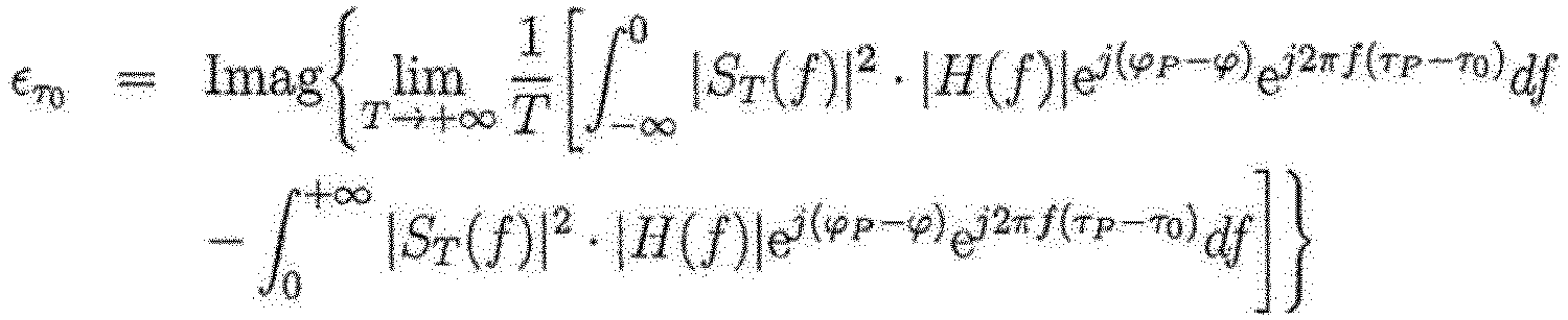
- Accordingly, it results:

- In case of τ0=τP the equation becomes zero. Values other than zero indicate with its sign a decrease or an increase for τ0. Again, a closed-loop control can be implemented for the adaption.
- For the adaption of the parameter α the real part of the cross-correlation function can be analyzed:

- For an ideal rectangle highpass filter H(f) with parameters τ0=τP and ϕ=ϕP the real part of the cross-correlation function becomes zero in case α=β. Values other than zero indicate with its sign again a needed decrease or increase of the amplification factor α.
- Accordingly, it has been shown that the phase, the amplitude and the delay of the compensation signal can be adaptively controlled to become an effective compensation of undesired frequency components outside the used channel in the transmission signal. However, the use of the cross-correlation function is only one possible example to do so.
- In the
data transmission device 1 according toFigure 1 the adapting means 12 are placed in afeedback path 11. The adapting means 12 further comprise implemented comparingmeans 14, which compare, for example with the aid of a cross-correlation function, the compensated transmission signal v(t) with the compensation signal c(t). - The
data transmission device 25 according toFigure 2 comprises amodulator 4, which generates a digital modulated carrier signal with a carrier frequency within an intermediate frequency band. A digital to analog converter DAC converts the digital modulated carrier signal, which is discrete in time and value, into an analog signal, which is continuous in time. Along thetransmission path 2 frequency components in the continuous modulated carrier signal are removed subsequently with a respective filter, which for example is realized with a bandpass filter. Downstream of the filter the signal is frequency up-converted to a RF signal by frequency-mixing. In a radio frequency synthesizer 15 a radio frequency local oscillator signal LO3 is generated, which is mixed in the frequency-mixer 18 with the modulated carrier signal. In another subsequent bandpass filter undesired mixing products are eliminated. The radio frequency signal is then amplified in thepower amplifier 5 to an intensity level needed for radio transmission. Undesired harmonics of the carrier frequency are removed in another filter. The output signal of the filter than in similar known devices will be used for radio transmission via theantenna 7. - The shown
data transmission device 25 additionally comprises acompensation path 3. For a compensation signal the digital output signal of themodulator 4 is also fed into afilter 9, which removes the frequency components of the digital modulated carrier signal within the used transmission channel. In digital adapting means 12 the filtered signal is adapted with regard to its amplitude, to its phase and/or to its delay time. In a subsequent digital to analog converter DAC a continuous compensation signal is generated. Undesired frequency components are eliminated with a filter. In afrequency mixer 18 the signal is frequency-up converted to a radio frequency compensation signal. For the up-conversion another radio frequency local oscillator signal LO1 of thesynthesizer 15 is used. In a downstream filter undesired mixing products are eliminated. Anamplifier 19 amplifies the compensation signal to the needed power level. In coupling means 10 the amplified compensation signal is subtracted from the amplified transmission signal. The undesired frequency components outside the own transmission channel are eliminated. The compensated transmission signal then is transmitted withantenna 7. - The amplitude, the phase and/or the delay time of the compensation signal are adaptively controlled. With coupling means 17 the compensated transmission signal along a
feedback path 11 is fed to anamplifier 20 and then frequency downconverted in afrequency mixer 18 to an intermediate carrier frequency. Another local oszillator signal LO2 of thesynthesizer 15 is used for the down-conversion. In a subsequent filter undesired mixing components are removed. With an analog to digital converter ADC the compensated transmission signal, used as a reference signal, is converted to a digital signal discrete in time and value. In comparingmeans 14 the digital reference signal is compared with the already adapted digital compensation signal. Based on that comparison the phase, the amplitude and/or the delay time of the compensation signal are modified with respective adapting means 12. - Along the
transmission path 5, anisolator 21 is placed upstream of theantenna 7. Reflection signals travelling back from theantenna 7 into thetransmission path 2 are removed. Thecoupling elements 17, which allow measuring of the compensated transmission signal in thetransmission path 2 are placed downstream of the coupling means 10. This avoids an undesired backtravelling of the compensation signal to thepower amplifier 5. - In
Figure 3 anotherdata transmission device 30 is shown. In contrast to thedata transmission device 20 according toFigure 2 a digital modulated carrier signal in themodulator 4 is generated as an IQ-signal, comprising an in-phase component and a quadrature-component. With separate digital-to-analog converters both components are converted to continuous signals. In quadrature-mixers 24 the in-phase component and the quadrature-component both are mixed to a radio frequency signal. Similar to thedevice 20 shown inFigure 2 mixers 24 are placed in thetransmission path 2, thecompensation path 3 and in thefeedback path 11 respectively. Local oscillator signals LO1, LO2 and LO3 of asynthesizer 15 are used for frequency up-conversion and for frequency down-conversion respectively. Preferably, they are derived from the same reference oscillator in order to maintain a fixed phase relationship. In the easiest case these signals are just buffered versions of the same source. -
Figures 4 to 8 show power density spectra of CPM modulated carrier signals at different stages in adata transmission device 1 similar toFigure 1 .Figure 4 shows the power spectral density of the modulated carrier signal s(t) generated in themodulator 4. The power density spectrum after having passed thefilter 9 with a rectangle highpass characteristic is shown inFigure 5 . The cutting frequency is choosen at 0.625 fs. The frequency components within the used transmission channel are removed. -
Figure 6 shows the amplified modulated carrier signal p(t) which has passed thepower amplifier 5. The power density spectrum has not been changed due to the fact that a modulated signal with a constant envelope wave form is used. -
Figure 7 displays the power density spectrum of the compensated transmission signal v(t). The undesired frequency components outside the used transmission channel are all removed. - Retransmission of the compensated transmission signal v(t) to the
power amplifier 5 will result in a reestablishment of the removed frequency components. This is shown inFigure 8 , which displays the power density spectrum of a re-amplified signal sK(t)=s(t)-sH(t), which is similar to the compensated signal v(t). The power density spectrum according toFigure 8 again shows significant spectral components outside the bandwidth of the used frequency channel. - Accordingly, as shown in
Figures 2 and3 isolators like circulators should be placed downstream of thepower amplifier 5. -
- 1
- device
- 2
- transmission path
- 3
- compensation path
- 4
- modulator
- 5
- amplifier
- 6
- transmitter
- 7
- antenna
- 9
- filter
- 10
- coupling means
- 11
- feedback path
- 12
- adapting means
- 14
- comparing means
- 15
- synthesizer
- 17
- coupling means
- 18
- frequency mixer
- 19
- amplifier
- 20
- amplifier
- 21
- isolator
- 24
- quadrature-mixer
- 25
- device
- 30
- device
- ak
- data
- s(t)
- modulated carrier signal
- sH(t)
- filtered modulated carrier signal
- c(t)
- compensation signal
- p(t)
- transmission signal
- v(t)
- compensated transmission signal
- τH
- delay time
- τP
- delay time
- τ0
- delay time
- α
- amplification factor
- β
- amplification factor
- ϕ
- phase
- ϕP
- phase
Claims (14)
- Method for transmitting data (ak),- wherein along a transmission path (2)(i) based on the data (ak) to be transmitted a modulated carrier signal (s(t)) is generated, the carrier signal (s(t)) having a carrier frequency (fS) within a given transmission channel, which is comprised of a number of frequencies (f), and(ii) the modulated carrier signal (s(t)) is amplified to a transmission signal (p(t)),- wherein along a compensation path (3)(i) the modulated carrier signal (s(t)) is filtered, whereby the frequency components within the transmission channel are removed, and(ii) at least one of a phase (ϕ), an amplitude (α) and a delay (τ0) of the filtered signal (sH(t)) is modified thereby generating a compensation signal (c(t)),- wherein the compensation signal (c(t)) is subtracted from the transmission signal (p(t)) thereby generating a compensated transmission signal (v(t)), and wherein the compensated transmission signal (v(t)) is transmitted, and- wherein along a feedback path (11) the compensated transmission signal (v(t)) is compared with the compensation signal (c(t)) or with the filtered signal sH(t), and at least one of the phase (ϕ), the amplitude (α) and the delay (τ0) of the compensation signal (c(t)) is adapted based on the comparison result.
- Method according to claim 1,
characterized in that
the modulated carrier signal (s(t)) is generated according to one of the methods of frequency modulation (FM), frequency shift keying modulation (FSK), phase modulation (PM), phase shift keying modulation (PSK) and continuous phase modulation (CPM). - Method according to one of the preceding claims,
characterized in that
the modulated carrier signal (s(t)) is amplified in the transmission path (2) with a non-linear power amplifier (5). - Method according to one of the preceding claims,
characterized in that
the modulated carrier signal (s(t)) along the transmission path (2) and the compensation signal (c(t)) along the compensation path (3) are each frequency up-converted to a RF signal. - Method according to claim 4,
characterized in that
the modulated carrier signal (s(t)) is generated with a carrier frequency (fS) within an intermediate frequency band, and both the modulated carrier signal (s(t)) and the compensation signal (c(t)) are frequency up-converted to a RF signal. - Method according to claim 4,
characterized in that
the modulated carrier signal (s(t)) is generated with an in-phase component (I) and with a quadrature component (Q), and both the modulated carrier signal (s(t)) and the compensation signal (c(t)) with a quadrature-mixer (24) are frequency up-converted to a RF signal. - Method according to one of the preceding claims,
characterized in that
the modulated carrier signal (s(t)) is generated as a digital signal, the digital signal being discrete in time and value. - Method according to claim 7,
characterized in that
the digital signal of the modulated carrier signal (s(t)) is digitally filtered and modified in at least one of a phase (ϕ), an amplitude (α) and a delay (τ0). - Method according to claim 8,
characterized in that
the cross-correlation of the compensated transmission signal (v(t)) and the compensation signal (c(t)) or the cross-correlation of the compensated transmission signal (v(t)) and the filtered signal sH(t) is regarded for comparison. - Method according to claim 8 or 9,
characterized in that
the compensated transmission signal (v(t)) is digitized and the digitized compensated transmission signal (v(t)) is compared with a digital signal of the compensation signal (c(t)). - Method according to one of the preceding claims,
characterized in that
the compensated transmission signal (v(t)) is transmitted with an antenna (7) by wireless transmission. - Method according to claim 11,
characterized in that
reflection signals from the antenna (7) back into the transmission path (2) are suppressed. - Method according to claim 12,
characterized in that
along the transmission path (2) a back travelling of the compensation signal (c(t)) to the non-linear amplifier (5) is suppressed. - Data transmission device (1, 25, 30) comprising,- along a transmission path (2)(i) a modulator (4) for generating a modulated carrier signal (s(t)),(ii) an amplifier (5) and(iii) a transmitter (6), and- along a compensation path (3)(i) a filter (9) and(ii) adapting means (12) for modifying at least one of a phase (ϕ), an amplitude (α) and a delay (τ0) of a signal (e.g. sH(t)) travelling along the compensation path (3) are comprised,- wherein further the compensation path (3) and the transmission path (2) are coupled in coupling means (10) located upstream of the transmitter (6), the coupling means (10) are designed for subtracting the output signal of the compensation path (3) from the output signal of the transmission path (2), and- wherein along a feedback path (11) comparing means (14) are comprised, the comparing means (14) are connected (i) with the transmission path (2) upstream of the transmitter (6) and downstream of the amplifier (5), (ii) with the compensation path (3) downstream of the adapting means (12), and (iii) with the adapting means (12), the comparing means (14) further are designed to control the adapting means (12) for modifying at least one of the phase (ϕ), the amplitude (α) and the delay (τ0) of the signal (e.g. sH(t)) travelling along the compensation path (3).
Applications Claiming Priority (2)
| Application Number | Priority Date | Filing Date | Title |
|---|---|---|---|
| EP15155267.6A EP3057279A1 (en) | 2015-02-16 | 2015-02-16 | Device and method for transmitting data |
| PCT/EP2016/052316 WO2016131656A1 (en) | 2015-02-16 | 2016-02-03 | Device and method for transmitting data |
Publications (2)
| Publication Number | Publication Date |
|---|---|
| EP3259892A1 EP3259892A1 (en) | 2017-12-27 |
| EP3259892B1 true EP3259892B1 (en) | 2020-03-25 |
Family
ID=52544309
Family Applications (2)
| Application Number | Title | Priority Date | Filing Date |
|---|---|---|---|
| EP15155267.6A Withdrawn EP3057279A1 (en) | 2015-02-16 | 2015-02-16 | Device and method for transmitting data |
| EP16706543.2A Active EP3259892B1 (en) | 2015-02-16 | 2016-02-03 | Device and method for transmitting data |
Family Applications Before (1)
| Application Number | Title | Priority Date | Filing Date |
|---|---|---|---|
| EP15155267.6A Withdrawn EP3057279A1 (en) | 2015-02-16 | 2015-02-16 | Device and method for transmitting data |
Country Status (3)
| Country | Link |
|---|---|
| US (1) | US10164816B2 (en) |
| EP (2) | EP3057279A1 (en) |
| WO (1) | WO2016131656A1 (en) |
Families Citing this family (1)
| Publication number | Priority date | Publication date | Assignee | Title |
|---|---|---|---|---|
| CN117439559B (en) * | 2023-10-20 | 2024-05-17 | 哈尔滨海鸿基业科技发展有限公司 | Power amplifying circuit for isolating pulse and control method |
Family Cites Families (5)
| Publication number | Priority date | Publication date | Assignee | Title |
|---|---|---|---|---|
| US5694433A (en) * | 1994-09-14 | 1997-12-02 | Ericsson Inc. | Efficient linear power amplification |
| US7129778B2 (en) * | 2003-07-23 | 2006-10-31 | Northrop Grumman Corporation | Digital cross cancellation system |
| KR100810322B1 (en) * | 2004-10-29 | 2008-03-07 | 삼성전자주식회사 | High efficiency power amplification device and method for mobile communication |
| US8615207B2 (en) * | 2010-02-01 | 2013-12-24 | Intersil Americas Inc. | Power amplifier linearization feedback methods and systems |
| US8565707B2 (en) * | 2011-10-13 | 2013-10-22 | Qualcomm Incorporated | Cancellation of spectral images in communication devices |
-
2015
- 2015-02-16 EP EP15155267.6A patent/EP3057279A1/en not_active Withdrawn
-
2016
- 2016-02-03 EP EP16706543.2A patent/EP3259892B1/en active Active
- 2016-02-03 WO PCT/EP2016/052316 patent/WO2016131656A1/en not_active Ceased
-
2017
- 2017-08-16 US US15/678,544 patent/US10164816B2/en active Active
Non-Patent Citations (1)
| Title |
|---|
| None * |
Also Published As
| Publication number | Publication date |
|---|---|
| WO2016131656A1 (en) | 2016-08-25 |
| US20180019907A1 (en) | 2018-01-18 |
| EP3259892A1 (en) | 2017-12-27 |
| EP3057279A1 (en) | 2016-08-17 |
| US10164816B2 (en) | 2018-12-25 |
Similar Documents
| Publication | Publication Date | Title |
|---|---|---|
| US8855580B2 (en) | Methods and apparatus for reducing own-transmitter interference in low-IF and zero-IF receivers | |
| US20100159837A1 (en) | Own Transmitter Interference Tolerant Transceiver and Receiving Methods | |
| WO2001054290A2 (en) | Method and apparatus for canceling a transit signal spectrum in a receiver bandwidth | |
| WO2007029429A1 (en) | Leakage signal canceller | |
| US20210050878A1 (en) | Integrated circuit for self-interference cancellation and method of performing full-duplex radio communication | |
| CA2947106C (en) | Method and measuring device for intermodulation measurement | |
| EP0999645B1 (en) | Data converter | |
| Dan et al. | Impact of modulation type and baud rate on a 300GHz fixed wireless link | |
| US11616527B2 (en) | Transmitter/receiver and signal generation method | |
| US10164816B2 (en) | Device and method for transmitting data | |
| CN110971257B (en) | Transceiver device | |
| US7876855B2 (en) | Phase modulation power spreading used to reduce RF or microwave transmitter output power spur levels | |
| US20100232530A1 (en) | Communication apparatus | |
| Allén et al. | Digital full-band linearization of wideband direct-conversion receiver for radar and communications applications | |
| US8638890B2 (en) | Generalized frequency modulation | |
| US9048920B2 (en) | Method and apparatus for reducing FM audio artifacts in a receiver | |
| EP2020087B1 (en) | An apparatus for monitoring non-linear distortions of radio signals and a method therefor | |
| US8731122B1 (en) | Spurious component reduction | |
| EP1380115B1 (en) | Transmitting device limiting the out-of-band interferences | |
| EP3028428B1 (en) | Direct conversion receiver device with first and second stages and related methods | |
| EP3005573B1 (en) | Distortion suppression for wireless transmission | |
| US10594343B2 (en) | Circuit arrangement and method for generating a radio-frequency, analogue transmission signal using reduced interference signals | |
| Xia et al. | A Frequency Domain Dual-Channel Identification and Suppression Approach for Harmonic Interferences in Software-Defined Radio Systems | |
| JP2009005085A (en) | High frequency pulse modulation device and high frequency radio device | |
| EP1120903A1 (en) | Transmission feedback system |
Legal Events
| Date | Code | Title | Description |
|---|---|---|---|
| STAA | Information on the status of an ep patent application or granted ep patent |
Free format text: STATUS: THE INTERNATIONAL PUBLICATION HAS BEEN MADE |
|
| PUAI | Public reference made under article 153(3) epc to a published international application that has entered the european phase |
Free format text: ORIGINAL CODE: 0009012 |
|
| STAA | Information on the status of an ep patent application or granted ep patent |
Free format text: STATUS: REQUEST FOR EXAMINATION WAS MADE |
|
| 17P | Request for examination filed |
Effective date: 20170913 |
|
| AK | Designated contracting states |
Kind code of ref document: A1 Designated state(s): AL AT BE BG CH CY CZ DE DK EE ES FI FR GB GR HR HU IE IS IT LI LT LU LV MC MK MT NL NO PL PT RO RS SE SI SK SM TR |
|
| AX | Request for extension of the european patent |
Extension state: BA ME |
|
| DAV | Request for validation of the european patent (deleted) | ||
| DAX | Request for extension of the european patent (deleted) | ||
| STAA | Information on the status of an ep patent application or granted ep patent |
Free format text: STATUS: EXAMINATION IS IN PROGRESS |
|
| 17Q | First examination report despatched |
Effective date: 20190218 |
|
| GRAP | Despatch of communication of intention to grant a patent |
Free format text: ORIGINAL CODE: EPIDOSNIGR1 |
|
| STAA | Information on the status of an ep patent application or granted ep patent |
Free format text: STATUS: GRANT OF PATENT IS INTENDED |
|
| RIC1 | Information provided on ipc code assigned before grant |
Ipc: H04L 27/12 20060101ALI20190924BHEP Ipc: H03F 3/24 20060101ALI20190924BHEP Ipc: H04B 1/04 20060101ALI20190924BHEP Ipc: H03F 1/32 20060101ALI20190924BHEP Ipc: H04L 27/36 20060101AFI20190924BHEP Ipc: H04L 27/20 20060101ALI20190924BHEP |
|
| INTG | Intention to grant announced |
Effective date: 20191021 |
|
| RAP1 | Party data changed (applicant data changed or rights of an application transferred) |
Owner name: UNIVERSITAET DER BUNDESWEHR MUENCHEN |
|
| GRAS | Grant fee paid |
Free format text: ORIGINAL CODE: EPIDOSNIGR3 |
|
| GRAA | (expected) grant |
Free format text: ORIGINAL CODE: 0009210 |
|
| STAA | Information on the status of an ep patent application or granted ep patent |
Free format text: STATUS: THE PATENT HAS BEEN GRANTED |
|
| AK | Designated contracting states |
Kind code of ref document: B1 Designated state(s): AL AT BE BG CH CY CZ DE DK EE ES FI FR GB GR HR HU IE IS IT LI LT LU LV MC MK MT NL NO PL PT RO RS SE SI SK SM TR |
|
| REG | Reference to a national code |
Ref country code: GB Ref legal event code: FG4D |
|
| REG | Reference to a national code |
Ref country code: DE Ref legal event code: R096 Ref document number: 602016032469 Country of ref document: DE |
|
| REG | Reference to a national code |
Ref country code: AT Ref legal event code: REF Ref document number: 1249879 Country of ref document: AT Kind code of ref document: T Effective date: 20200415 Ref country code: IE Ref legal event code: FG4D |
|
| PG25 | Lapsed in a contracting state [announced via postgrant information from national office to epo] |
Ref country code: FI Free format text: LAPSE BECAUSE OF FAILURE TO SUBMIT A TRANSLATION OF THE DESCRIPTION OR TO PAY THE FEE WITHIN THE PRESCRIBED TIME-LIMIT Effective date: 20200325 Ref country code: NO Free format text: LAPSE BECAUSE OF FAILURE TO SUBMIT A TRANSLATION OF THE DESCRIPTION OR TO PAY THE FEE WITHIN THE PRESCRIBED TIME-LIMIT Effective date: 20200625 Ref country code: RS Free format text: LAPSE BECAUSE OF FAILURE TO SUBMIT A TRANSLATION OF THE DESCRIPTION OR TO PAY THE FEE WITHIN THE PRESCRIBED TIME-LIMIT Effective date: 20200325 |
|
| PG25 | Lapsed in a contracting state [announced via postgrant information from national office to epo] |
Ref country code: GR Free format text: LAPSE BECAUSE OF FAILURE TO SUBMIT A TRANSLATION OF THE DESCRIPTION OR TO PAY THE FEE WITHIN THE PRESCRIBED TIME-LIMIT Effective date: 20200626 Ref country code: HR Free format text: LAPSE BECAUSE OF FAILURE TO SUBMIT A TRANSLATION OF THE DESCRIPTION OR TO PAY THE FEE WITHIN THE PRESCRIBED TIME-LIMIT Effective date: 20200325 Ref country code: LV Free format text: LAPSE BECAUSE OF FAILURE TO SUBMIT A TRANSLATION OF THE DESCRIPTION OR TO PAY THE FEE WITHIN THE PRESCRIBED TIME-LIMIT Effective date: 20200325 Ref country code: SE Free format text: LAPSE BECAUSE OF FAILURE TO SUBMIT A TRANSLATION OF THE DESCRIPTION OR TO PAY THE FEE WITHIN THE PRESCRIBED TIME-LIMIT Effective date: 20200325 Ref country code: BG Free format text: LAPSE BECAUSE OF FAILURE TO SUBMIT A TRANSLATION OF THE DESCRIPTION OR TO PAY THE FEE WITHIN THE PRESCRIBED TIME-LIMIT Effective date: 20200625 |
|
| REG | Reference to a national code |
Ref country code: NL Ref legal event code: MP Effective date: 20200325 |
|
| REG | Reference to a national code |
Ref country code: LT Ref legal event code: MG4D |
|
| PG25 | Lapsed in a contracting state [announced via postgrant information from national office to epo] |
Ref country code: NL Free format text: LAPSE BECAUSE OF FAILURE TO SUBMIT A TRANSLATION OF THE DESCRIPTION OR TO PAY THE FEE WITHIN THE PRESCRIBED TIME-LIMIT Effective date: 20200325 |
|
| PG25 | Lapsed in a contracting state [announced via postgrant information from national office to epo] |
Ref country code: LT Free format text: LAPSE BECAUSE OF FAILURE TO SUBMIT A TRANSLATION OF THE DESCRIPTION OR TO PAY THE FEE WITHIN THE PRESCRIBED TIME-LIMIT Effective date: 20200325 Ref country code: CZ Free format text: LAPSE BECAUSE OF FAILURE TO SUBMIT A TRANSLATION OF THE DESCRIPTION OR TO PAY THE FEE WITHIN THE PRESCRIBED TIME-LIMIT Effective date: 20200325 Ref country code: RO Free format text: LAPSE BECAUSE OF FAILURE TO SUBMIT A TRANSLATION OF THE DESCRIPTION OR TO PAY THE FEE WITHIN THE PRESCRIBED TIME-LIMIT Effective date: 20200325 Ref country code: PT Free format text: LAPSE BECAUSE OF FAILURE TO SUBMIT A TRANSLATION OF THE DESCRIPTION OR TO PAY THE FEE WITHIN THE PRESCRIBED TIME-LIMIT Effective date: 20200818 Ref country code: SK Free format text: LAPSE BECAUSE OF FAILURE TO SUBMIT A TRANSLATION OF THE DESCRIPTION OR TO PAY THE FEE WITHIN THE PRESCRIBED TIME-LIMIT Effective date: 20200325 Ref country code: IS Free format text: LAPSE BECAUSE OF FAILURE TO SUBMIT A TRANSLATION OF THE DESCRIPTION OR TO PAY THE FEE WITHIN THE PRESCRIBED TIME-LIMIT Effective date: 20200725 Ref country code: SM Free format text: LAPSE BECAUSE OF FAILURE TO SUBMIT A TRANSLATION OF THE DESCRIPTION OR TO PAY THE FEE WITHIN THE PRESCRIBED TIME-LIMIT Effective date: 20200325 Ref country code: EE Free format text: LAPSE BECAUSE OF FAILURE TO SUBMIT A TRANSLATION OF THE DESCRIPTION OR TO PAY THE FEE WITHIN THE PRESCRIBED TIME-LIMIT Effective date: 20200325 |
|
| REG | Reference to a national code |
Ref country code: AT Ref legal event code: MK05 Ref document number: 1249879 Country of ref document: AT Kind code of ref document: T Effective date: 20200325 |
|
| REG | Reference to a national code |
Ref country code: DE Ref legal event code: R097 Ref document number: 602016032469 Country of ref document: DE |
|
| PG25 | Lapsed in a contracting state [announced via postgrant information from national office to epo] |
Ref country code: ES Free format text: LAPSE BECAUSE OF FAILURE TO SUBMIT A TRANSLATION OF THE DESCRIPTION OR TO PAY THE FEE WITHIN THE PRESCRIBED TIME-LIMIT Effective date: 20200325 Ref country code: DK Free format text: LAPSE BECAUSE OF FAILURE TO SUBMIT A TRANSLATION OF THE DESCRIPTION OR TO PAY THE FEE WITHIN THE PRESCRIBED TIME-LIMIT Effective date: 20200325 Ref country code: AT Free format text: LAPSE BECAUSE OF FAILURE TO SUBMIT A TRANSLATION OF THE DESCRIPTION OR TO PAY THE FEE WITHIN THE PRESCRIBED TIME-LIMIT Effective date: 20200325 Ref country code: IT Free format text: LAPSE BECAUSE OF FAILURE TO SUBMIT A TRANSLATION OF THE DESCRIPTION OR TO PAY THE FEE WITHIN THE PRESCRIBED TIME-LIMIT Effective date: 20200325 |
|
| PLBE | No opposition filed within time limit |
Free format text: ORIGINAL CODE: 0009261 |
|
| STAA | Information on the status of an ep patent application or granted ep patent |
Free format text: STATUS: NO OPPOSITION FILED WITHIN TIME LIMIT |
|
| PG25 | Lapsed in a contracting state [announced via postgrant information from national office to epo] |
Ref country code: PL Free format text: LAPSE BECAUSE OF FAILURE TO SUBMIT A TRANSLATION OF THE DESCRIPTION OR TO PAY THE FEE WITHIN THE PRESCRIBED TIME-LIMIT Effective date: 20200325 |
|
| 26N | No opposition filed |
Effective date: 20210112 |
|
| PG25 | Lapsed in a contracting state [announced via postgrant information from national office to epo] |
Ref country code: SI Free format text: LAPSE BECAUSE OF FAILURE TO SUBMIT A TRANSLATION OF THE DESCRIPTION OR TO PAY THE FEE WITHIN THE PRESCRIBED TIME-LIMIT Effective date: 20200325 |
|
| PG25 | Lapsed in a contracting state [announced via postgrant information from national office to epo] |
Ref country code: MC Free format text: LAPSE BECAUSE OF FAILURE TO SUBMIT A TRANSLATION OF THE DESCRIPTION OR TO PAY THE FEE WITHIN THE PRESCRIBED TIME-LIMIT Effective date: 20200325 |
|
| REG | Reference to a national code |
Ref country code: BE Ref legal event code: MM Effective date: 20210228 |
|
| PG25 | Lapsed in a contracting state [announced via postgrant information from national office to epo] |
Ref country code: LI Free format text: LAPSE BECAUSE OF NON-PAYMENT OF DUE FEES Effective date: 20210228 Ref country code: LU Free format text: LAPSE BECAUSE OF NON-PAYMENT OF DUE FEES Effective date: 20210203 Ref country code: CH Free format text: LAPSE BECAUSE OF NON-PAYMENT OF DUE FEES Effective date: 20210228 |
|
| PG25 | Lapsed in a contracting state [announced via postgrant information from national office to epo] |
Ref country code: IE Free format text: LAPSE BECAUSE OF NON-PAYMENT OF DUE FEES Effective date: 20210203 |
|
| PG25 | Lapsed in a contracting state [announced via postgrant information from national office to epo] |
Ref country code: BE Free format text: LAPSE BECAUSE OF NON-PAYMENT OF DUE FEES Effective date: 20210228 |
|
| PG25 | Lapsed in a contracting state [announced via postgrant information from national office to epo] |
Ref country code: CY Free format text: LAPSE BECAUSE OF FAILURE TO SUBMIT A TRANSLATION OF THE DESCRIPTION OR TO PAY THE FEE WITHIN THE PRESCRIBED TIME-LIMIT Effective date: 20200325 |
|
| PG25 | Lapsed in a contracting state [announced via postgrant information from national office to epo] |
Ref country code: HU Free format text: LAPSE BECAUSE OF FAILURE TO SUBMIT A TRANSLATION OF THE DESCRIPTION OR TO PAY THE FEE WITHIN THE PRESCRIBED TIME-LIMIT; INVALID AB INITIO Effective date: 20160203 |
|
| PG25 | Lapsed in a contracting state [announced via postgrant information from national office to epo] |
Ref country code: MK Free format text: LAPSE BECAUSE OF FAILURE TO SUBMIT A TRANSLATION OF THE DESCRIPTION OR TO PAY THE FEE WITHIN THE PRESCRIBED TIME-LIMIT Effective date: 20200325 |
|
| REG | Reference to a national code |
Ref country code: DE Ref legal event code: R082 Ref document number: 602016032469 Country of ref document: DE Representative=s name: MICHALSKI HUETTERMANN & PARTNER PATENTANWAELTE, DE Ref country code: DE Ref legal event code: R081 Ref document number: 602016032469 Country of ref document: DE Owner name: NEOSAT GMBH, DE Free format text: FORMER OWNER: UNIVERSITAET DER BUNDESWEHR MUENCHEN, 85579 NEUBIBERG, DE Ref country code: DE Ref legal event code: R082 Ref document number: 602016032469 Country of ref document: DE Representative=s name: MICHALSKI HUETTERMANN & PARTNER MBB, DE |
|
| PG25 | Lapsed in a contracting state [announced via postgrant information from national office to epo] |
Ref country code: MT Free format text: LAPSE BECAUSE OF FAILURE TO SUBMIT A TRANSLATION OF THE DESCRIPTION OR TO PAY THE FEE WITHIN THE PRESCRIBED TIME-LIMIT Effective date: 20200325 |
|
| REG | Reference to a national code |
Ref country code: GB Ref legal event code: 732E Free format text: REGISTERED BETWEEN 20240912 AND 20240918 |
|
| PG25 | Lapsed in a contracting state [announced via postgrant information from national office to epo] |
Ref country code: TR Free format text: LAPSE BECAUSE OF FAILURE TO SUBMIT A TRANSLATION OF THE DESCRIPTION OR TO PAY THE FEE WITHIN THE PRESCRIBED TIME-LIMIT Effective date: 20200325 |
|
| PGFP | Annual fee paid to national office [announced via postgrant information from national office to epo] |
Ref country code: GB Payment date: 20260219 Year of fee payment: 11 |
|
| PGFP | Annual fee paid to national office [announced via postgrant information from national office to epo] |
Ref country code: DE Payment date: 20260225 Year of fee payment: 11 |
|
| PGFP | Annual fee paid to national office [announced via postgrant information from national office to epo] |
Ref country code: FR Payment date: 20260218 Year of fee payment: 11 |