EP3259489B1 - Multi-performance hysteretic rheological device - Google Patents
Multi-performance hysteretic rheological device Download PDFInfo
- Publication number
- EP3259489B1 EP3259489B1 EP16722955.8A EP16722955A EP3259489B1 EP 3259489 B1 EP3259489 B1 EP 3259489B1 EP 16722955 A EP16722955 A EP 16722955A EP 3259489 B1 EP3259489 B1 EP 3259489B1
- Authority
- EP
- European Patent Office
- Prior art keywords
- frame
- psg
- wire ropes
- hysteretic
- rigid
- Prior art date
- Legal status (The legal status is an assumption and is not a legal conclusion. Google has not performed a legal analysis and makes no representation as to the accuracy of the status listed.)
- Active
Links
Images




Classifications
-
- B—PERFORMING OPERATIONS; TRANSPORTING
- B60—VEHICLES IN GENERAL
- B60R—VEHICLES, VEHICLE FITTINGS, OR VEHICLE PARTS, NOT OTHERWISE PROVIDED FOR
- B60R19/00—Wheel guards; Radiator guards, e.g. grilles; Obstruction removers; Fittings damping bouncing force in collisions
- B60R19/02—Bumpers, i.e. impact receiving or absorbing members for protecting vehicles or fending off blows from other vehicles or objects
- B60R19/18—Bumpers, i.e. impact receiving or absorbing members for protecting vehicles or fending off blows from other vehicles or objects characterised by the cross-section; Means within the bumper to absorb impact
-
- B—PERFORMING OPERATIONS; TRANSPORTING
- B60—VEHICLES IN GENERAL
- B60R—VEHICLES, VEHICLE FITTINGS, OR VEHICLE PARTS, NOT OTHERWISE PROVIDED FOR
- B60R19/00—Wheel guards; Radiator guards, e.g. grilles; Obstruction removers; Fittings damping bouncing force in collisions
- B60R19/02—Bumpers, i.e. impact receiving or absorbing members for protecting vehicles or fending off blows from other vehicles or objects
- B60R19/24—Arrangements for mounting bumpers on vehicles
- B60R19/26—Arrangements for mounting bumpers on vehicles comprising yieldable mounting means
- B60R19/34—Arrangements for mounting bumpers on vehicles comprising yieldable mounting means destroyed upon impact, e.g. one-shot type
-
- F—MECHANICAL ENGINEERING; LIGHTING; HEATING; WEAPONS; BLASTING
- F16—ENGINEERING ELEMENTS AND UNITS; GENERAL MEASURES FOR PRODUCING AND MAINTAINING EFFECTIVE FUNCTIONING OF MACHINES OR INSTALLATIONS; THERMAL INSULATION IN GENERAL
- F16F—SPRINGS; SHOCK-ABSORBERS; MEANS FOR DAMPING VIBRATION
- F16F15/00—Suppression of vibrations in systems; Means or arrangements for avoiding or reducing out-of-balance forces, e.g. due to motion
- F16F15/02—Suppression of vibrations of non-rotating, e.g. reciprocating systems; Suppression of vibrations of rotating systems by use of members not moving with the rotating systems
- F16F15/04—Suppression of vibrations of non-rotating, e.g. reciprocating systems; Suppression of vibrations of rotating systems by use of members not moving with the rotating systems using elastic means
- F16F15/06—Suppression of vibrations of non-rotating, e.g. reciprocating systems; Suppression of vibrations of rotating systems by use of members not moving with the rotating systems using elastic means with metal springs
-
- F—MECHANICAL ENGINEERING; LIGHTING; HEATING; WEAPONS; BLASTING
- F16—ENGINEERING ELEMENTS AND UNITS; GENERAL MEASURES FOR PRODUCING AND MAINTAINING EFFECTIVE FUNCTIONING OF MACHINES OR INSTALLATIONS; THERMAL INSULATION IN GENERAL
- F16F—SPRINGS; SHOCK-ABSORBERS; MEANS FOR DAMPING VIBRATION
- F16F7/00—Vibration-dampers; Shock-absorbers
- F16F7/10—Vibration-dampers; Shock-absorbers using inertia effect
- F16F7/1005—Vibration-dampers; Shock-absorbers using inertia effect characterised by active control of the mass
-
- F—MECHANICAL ENGINEERING; LIGHTING; HEATING; WEAPONS; BLASTING
- F16—ENGINEERING ELEMENTS AND UNITS; GENERAL MEASURES FOR PRODUCING AND MAINTAINING EFFECTIVE FUNCTIONING OF MACHINES OR INSTALLATIONS; THERMAL INSULATION IN GENERAL
- F16F—SPRINGS; SHOCK-ABSORBERS; MEANS FOR DAMPING VIBRATION
- F16F7/00—Vibration-dampers; Shock-absorbers
- F16F7/10—Vibration-dampers; Shock-absorbers using inertia effect
- F16F7/104—Vibration-dampers; Shock-absorbers using inertia effect the inertia member being resiliently mounted
- F16F7/116—Vibration-dampers; Shock-absorbers using inertia effect the inertia member being resiliently mounted on metal springs
-
- F—MECHANICAL ENGINEERING; LIGHTING; HEATING; WEAPONS; BLASTING
- F16—ENGINEERING ELEMENTS AND UNITS; GENERAL MEASURES FOR PRODUCING AND MAINTAINING EFFECTIVE FUNCTIONING OF MACHINES OR INSTALLATIONS; THERMAL INSULATION IN GENERAL
- F16F—SPRINGS; SHOCK-ABSORBERS; MEANS FOR DAMPING VIBRATION
- F16F7/00—Vibration-dampers; Shock-absorbers
- F16F7/14—Vibration-dampers; Shock-absorbers of cable support type, i.e. frictionally-engaged loop-forming cables
-
- F—MECHANICAL ENGINEERING; LIGHTING; HEATING; WEAPONS; BLASTING
- F16—ENGINEERING ELEMENTS AND UNITS; GENERAL MEASURES FOR PRODUCING AND MAINTAINING EFFECTIVE FUNCTIONING OF MACHINES OR INSTALLATIONS; THERMAL INSULATION IN GENERAL
- F16F—SPRINGS; SHOCK-ABSORBERS; MEANS FOR DAMPING VIBRATION
- F16F2222/00—Special physical effects, e.g. nature of damping effects
- F16F2222/08—Inertia
-
- F—MECHANICAL ENGINEERING; LIGHTING; HEATING; WEAPONS; BLASTING
- F16—ENGINEERING ELEMENTS AND UNITS; GENERAL MEASURES FOR PRODUCING AND MAINTAINING EFFECTIVE FUNCTIONING OF MACHINES OR INSTALLATIONS; THERMAL INSULATION IN GENERAL
- F16F—SPRINGS; SHOCK-ABSORBERS; MEANS FOR DAMPING VIBRATION
- F16F2224/00—Materials; Material properties
- F16F2224/02—Materials; Material properties solids
- F16F2224/0258—Shape-memory metals, e.g. Ni-Ti alloys
-
- F—MECHANICAL ENGINEERING; LIGHTING; HEATING; WEAPONS; BLASTING
- F16—ENGINEERING ELEMENTS AND UNITS; GENERAL MEASURES FOR PRODUCING AND MAINTAINING EFFECTIVE FUNCTIONING OF MACHINES OR INSTALLATIONS; THERMAL INSULATION IN GENERAL
- F16F—SPRINGS; SHOCK-ABSORBERS; MEANS FOR DAMPING VIBRATION
- F16F2228/00—Functional characteristics, e.g. variability, frequency-dependence
- F16F2228/06—Stiffness
- F16F2228/066—Variable stiffness
Definitions
- the present invention relates to a multi-performance hysteretic rheological device.
- the invention concerns a mechanical system capable of providing restoring forces characterized by non-linear hysteresis loops, whose shapes can be adjusted depending on the specifications required by the application.
- the forces are to be carried for example by wire ropes composed of steel and shape-memory material wires.
- the system is represented by a closed frame within which groups of wire ropes are housed, connected on one side to two parallel uprights and on the other side to a pair of rigid metal elements subject to equal displacement for the presence of two smooth bars crossing them and on which they can slide substantially without friction.
- Such smooth bars are fixed in the center line to a further central metallic element with respect to the other, which in turn can slide without friction on two additional smooth bars orthogonal to the previous ones and which act as guide shafts.
- the latter are fixed to the ends to two parallel sides of the closed frame.
- the set of the three elements and of the two smooth bars crossing them constitutes the secondary frame whose translation relative to the closed frame in the direction orthogonal to the ropes produces the nonlinear hysteretic restoring forces.
- the secondary frame acts as vibrating mass, being capable of sliding on the underlying guides, the device operates as a vibrations damper.
- the rod becomes a dissipative damping brace thanks to the dissipation exerted by the mechanism.
- the device is configured in such a way that the sliding central element supports a structure while the closed frame is fixed to a base subject to undesirable motions (e.g.
- the body acts as a vibrations hysteretic isolator for the main structure.
- the closed frame is fixed on a movable member and the secondary frame impacts on an obstacle, the device exerts its action by absorbing shocks.
- the first tuned mass damper based on energy dissipated by friction between the wires of steel ropes is the Stockbridge Damper [1] patented in 1928.
- This device consists of a short wire rope tied in the middle and at whose ends two free oscillating masses are fixed. Its use is to reduce dynamic vibrations induced by the wind on the high voltage cables.
- a hysteretic insulator [2] which is formed by two parallel metal bars connected with a coil constituted by a steel rope.
- the latter provides a hysteretic-type restoring force to the relative translation between the two bars.
- the idea is to fix a bar and connect to the other one the structure to be insulated.
- the so-called "wire ropes springs” have been created, represented by steel ropes arranged in the shape of coil, which have been spread along time on a commercial level.
- Articles [4] and [5] synthetically describe the interaction of the mechanisms of dissipation by friction and phase transformation of the shape-memory material and the ensuing positive effect in terms of equivalent damping.
- the non-linear vibrations absorbers in the present state of the art suffer from a loss of tuning, and thus a loss of performance in attenuating the vibrations of a main structure by the effect of the significant variation of damping and resonance frequency as a function of the oscillation amplitude.
- the device of reference [3] cannot be used, for example, as hysteretic isolator, since it is not possible to fix the structure to be insulated to the oscillating masses, both because these masses cannot provide a support, and because during the oscillations they are subject to rotations with respect to the rest configuration orthogonal to the ropes.
- Grasser and Cozzarelli proposed the shape-memory alloys as a new material for the seismic isolation.
- Wilde, Gordoni and Fujino [7] proposed the idea of combining the classic reinforced rubber supports with elements made of shape-memory alloy, for the isolation of bridge decks.
- Van Zeggeren in 1991 [9] proposed a shock absorber based on an actuator constituted by a wire spring in a shape-memory alloy.
- the object of the present invention is to provide a hysteretic device that solves the problems and overcomes the drawbacks of the prior art.
- the invention relates to a multi-purpose mechanical device capable of providing non-linear hysteretic restoring forces with adjustable properties.
- the device can be used in very different applications including: (1) vibration damper, (2) hysteretic insulator, (3) energy absorber, (4) shock absorber, (5) applications which require a specific rheological system with force-displacement characteristics of the hysteretic type.
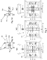
- FIG 1 a schematic representation of a specific illustrative embodiment of the device according to the invention is shown.
- the device comprises a main frame F1 of rectangular shape constituted by four rods F1-a, F1-b, F1-c and F1-d that form its sides.
- F1-a and F1-b rods arranged along the direction that will be indicated as vertical, clamping devices F1-a1 and F1-b1 are respectively placed, to which the ends of a group of ropes or cables of different type, indicated with the term PSG, are fixed.
- the other ends of the group of ropes PSG are fixed to two facing blocks b2 that contain joints b2-1.
- the ropes PSG in the resting configuration (balance in the absence of load or absence of mechanical vibrations) of the device are perpendicular to said vertical direction and then lie in the horizontal direction.
- the two elements or facing rigid blocks b2 are mounted so that they are movable along the vertical direction.
- a third element or rigid block b1 is positioned.
- the three blocks b1 and b2 are connected either rigidly or in such a way that the two rigid blocks b2 can move with respect to one another in the horizontal direction, though obviously affected by the restoring forces of the rope(s) PSG.
- the three blocks are crossed by two smooth bars S1 and S2 (or even just a bar S1 or S2, or more than two bars, or more generally one or more horizontal guides), perpendicular to the vertical direction, which are fixed (for example in their center line) to the block b1.
- the blocks b2 are supported by smooth bars S1 and S2 and can slide over them in the horizontal direction with low or adjustable friction by the interposition of bearings (e.g. bearings made of self-lubricated Teflon) or other known and future systems.
- the bars S1 and S2 may be each constituted by two semi-bars fixed at one end to b1.
- the set of the three blocks b1, b2 and smooth bars S1, S2 (referred to as the secondary frame F2) is structured so as to have the same vertical displacement.
- the third block b1 can slide in a vertical direction along at least a vertical guide, in particular at least two guides G1 and G2, (or even a single guide G1 or G2, or more guides) with reduced friction through bearings (for example, ball bearings).
- a vertical guide in particular at least two guides G1 and G2, (or even a single guide G1 or G2, or more guides) with reduced friction through bearings (for example, ball bearings).
- the above ropes can be, for example, (1) steel wire ropes (2) shape memory alloys wire ropes (SMA, "Shape-Memory Alloy"), including Nitinol (SMA alloy consisting of nickel and titanium) or other SMA alloys (some examples of which are, without limitation, NiAl, CuSn, CuMn, CuAlNi, CuAlZn, FeTi, FePt, FeMnSi), (3) mixed ropes consisting of steel wires and Nitinol wires or other shape memory alloys, (4) individual Nitinol (or other shape-memory alloy) wires.
- SMA shape memory alloys wire ropes
- Nitinol SMA alloy consisting of nickel and titanium
- other SMA alloys include NiAl, CuSn, CuMn, CuAlNi, CuAlZn, FeTi, FePt, FeMnSi
- mixed ropes consisting of steel wires and Nitinol wires or other shape memory alloy
- the device according to the invention may also contain a threaded bar S3 (preferably of circular section and parallel to the smooth bars S1, S2) fixed to the block b1 (for example in the center line) which passes through the blocks b2 without touching them and on which BO bolts are screwed.
- the latter have the function of rigidly connecting block b1 to blocks b2 in such a way that the sliding on guides S1, S2 is prevented, and therefore there are no relative translations in the horizontal direction of the blocks of the frame F2.
- Bar S3 has the function of making the device usable in a versatile way according to three different mechanisms that will be subject to detailed description hereinafter.
- the group of PSG ropes which connects the frame F1 to the bars b2 of frame F2 represents the group of principal stiffness of the device.
- the device can also optionally contain a SSG group of ropes or wires (secondary stiffness group), made of steel or shape-memory alloy or also of a mixture of both materials, that connect the two bars b2 (thanks to the joints b2-1) with each other, crossing the bar b1 through suitable holes.
- the device can also become semi-active by passing the electric current in the cables and/or wires made of shape memory alloy constituting groups PSG and/or SSG. In this manner the thermal state of the cables and/or wires is varied by Joule effect and the mechanical properties (stiffness) of the shape-memory alloy can be adjusted in real time according to the operating needs.
- the frame F1 is fixed to the piston P of a test machine (for example, of the type MTS - Material Testing System) and bar b1 of frame F2 is bound by a fork to the fixed support R of the machine.
- the frame F1 is cyclically moved in a vertical direction and a load cell L, positioned between the fork and the fixed support of the machine MTS, measures the restoring force of the system.
- the frame F1, the stiffness groups of PSG and SSG, the elements b2 and the guides G1 and G2 are represented in the respective configurations varied with dashed lines.
- the restoring forces provided by the device are of non-linear hysteretic type, whose stiffness properties vary with continuity during the stages of loading or unloading (i.e. the stiffness of the device, represented by the derivative of the restoring force with respect to the displacement, is a continuous function of the displacement except in the reversal points of the displacement speed, or points of reversal of the sign of the load direction), undergoing discontinuous changes in the points of load-unload reversal and vice versa.
- the dissipative capabilities are due to two mechanisms: 1) the internal friction between the wires subjected to relative sliding, and (2) the phase transformation of austenite-martensite (under loading) and vice versa (under unloading) induced by the variation in the tension-deformation state in the shape-memory alloy.
- the concomitance of these dissipative mechanisms determines a hysteretic force-displacement cycle (relative displacement of F1 with respect to F2) characterized by a variation of the dissipated energy, which is incremented during the loading phase and is reduced during the unloading one.
- the restoring forces obtained using the three different modes (M1, M2 and M3) with use of various ropes are represented in Figure 3 .
- the curve in Figure 3(a) has been obtained with the device in the M2 mode by using steel ropes as PSG.
- the dissipation is due to the friction between the wires and the force-displacement relationship is of quasi-linear softening type; a result similar to that of the patent application device [3] is obtained.
- the constitutive behavior in Figure 3(c) was obtained with the device in the M1 mode and ropes entirely consisting of Nitinol as PSG Group.
- the hardening effect is of geometric type and is induced by the traction forces developed in the ropes.
- the damping is given by the friction between the wires and the phase transformations of NiTiNOL that are of prime importance.
- the curve in Figure 3(d) was obtained with the device in the M3 mode and using steel ropes as PSG and wires of Nitinol as SSG. In this configuration, a damping is provided both by the friction and by the martensite-austenite phase transformations.
- the constitutive behavior softening with pinching, represented in Figure 3(b) is obtained by using the device in the M2 mode and the main group of stiffness PSG consists of steel-Nitinol mixed ropes. The pinching is due to the simultaneous presence of friction between the wires and phase transformations of the Nitinol.
- the friction provides a constant energy dissipation rate during the loading/unloading cycles.
- the Nitinol has a martensitic transition at the load application and an austenitic transition at the removal of load with the return to the elastic branch. This determines the variation of the rate of dissipation along the cycle producing the pinching effect.
- Figure 5 shows the device horizontally mounted on a vibrating table.
- the frame F2 can slide on the two vertical linear guides of Figure 1 by the ball bearings.
- the frame F1 is rigidly connected to the vibrating table, which is subject to imposed motion while the frame F2 is the oscillating mass.
- the configuration of Figure 5 is the mode by which it is possible to experimentally obtain the frequency response curves of the device, which can operate in three different modes M1, M2, and M3.
- the configuration of device DI in Figure 6 represents the embodiment as a tuned-mass damper in the case of a multi-storey building.
- the frame F1 is fixed on the structure PA to be controlled (see figure 6 (c) ) and F2, oscillating relatively to it, applies the control force as reactive forces at the connection points between F1 and the main structure.
- Figure 6 (b) only the frame F1 is fixed, having removed the frame F2. In this way, it has been possible to compare the controlled and uncontrolled oscillations of the fifth floor of structure PA.
- the non-linear vibrations absorbers present in the prior art show a limit in the loss of tuning, and thus loss of performance to attenuate the vibrations of a main structure, because of the significant variation of damping and resonant frequency with varying oscillation amplitude.
- the softening with pinching type behavior is able to overcome this drawback by exploiting the range of amplitudes in which both the resonant frequency and the damping keep almost constant.
- the device according to the invention may use tuned masses of high weight, thanks to the vertical guides (which support the weight), and eliminate the effects due to the rotation of the tuned masses, thanks to the horizontal guides (that bind them to translate along a straight direction).
- the relevant guides are arranged orthogonally, on which the oscillating masses slide (without connecting the two tuned dampers), a bi-directional damping system is obtained, which has ability of control on the two selected modes.
- the F1 frame could also be integrated in the main structure, for example, housing directly on it the joints for the ends of the ropes PSG and the fasteners for the guides G1 and G2.
- the performance of the damper have been evaluated experimentally considering a reduced scale multi-storey steel building mounted on a vibrating table.
- the damper has the task of dampening oscillations dominated by the first mode of vibration of the frame structure, the oscillations being induced by a harmonic motion at the base.
- Figure 6 (a) shows the entire multi-storey building located on the vibrating table and the absorber according to the invention housed on the top floor.
- Figure 6 (b) and (c) the non-controlled configuration (without F2) and controlled (with F1 and F2) are shown, respectively.
- the frequency response curves of the fifth storey of the non-controlled frame (represented by circles without filling color) and controlled frame (represented by circles with filling black color) are compared in Figure 7 (a) for a given level of amplitude of the forcer.
- the device is able to reduce by about 70% the shift in resonance of the fifth storey.
- the corresponding frequency response of the damper is shown in figure 7 (b) .
- the performance of the hysteretic damper was also evaluated against seismic motions at the base.
- Figure 8 shows the experimental response in acceleration of the fifth storey of the frame in a controlled configuration (by the gray curve) and not controlled configuration (by the black curve), while considering a seismic accelerogram imposed to the base.
- the peak in acceleration is attenuated by more than 70% and the Arias intensity of the controlled and not controlled response, respectively, is equal to 0,321 m/s and 1.43 m/s.
- the hysteretic mechanism obtained with ropes and wires of different kind constituting the principal group of stiffness PSG and the possible secondary stiffness group SSG integrated in the device described above according to the three different operating modes (M1, M2 and M3), can be used effectively as hysteretic isolator, dissipative bracing and shock absorber.
- M1, M2 and M3 three different operating modes
- the device can be used as hysteretic insulator for structures, equipment or components of various sizes and shapes.
- Figure 9 (a) shows three devices DI situated below the vertical bearing elements (termed pillars) of a building, and having hysteretic isolators function.
- a hysteretic isolator is realized (see Figure 10 (a) ), whose optimum constitutive behavior can be realized by exploiting several assemblies of integrated ropes in the three modes of functioning M1, M2, and M3.
- hysteretic insulator in a civil structure is purely indicative, since the device can be used for any main structure sensitive to deterioration effects of vibrations, such as for example: biomedical, nuclear, mechanical precision equipments; towers, silos, storage tanks.
- This list is partial, while using the device according to the invention is general, since it deals with any isolation application context, meaning by the latter the relative translation of a body with respect to another body regulated by the restoring force exerted by the device itself that causes a significant reduction of the isolated body resonance frequency.
- the insulator can be modified from unidirectional to two-directional in order to allow displacements in two orthogonal directions.
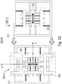
- Figure 11 illustrates the bi-directional insulator formed by the superposition of two unidirectional devices, "DI-1" and "DI-2".
- the frame F1 of the device DI-1 is fixed to the source of the undesired motion and element b1 of the DI-1 device is modified to accommodate the frame F1 of device DI-2.
- element b1 of the DI-1 device is modified to accommodate the frame F1 of device DI-2.
- the body to be isolated is connected to the element b1 belonging to the frame F2 of the device DI-2 and, accordingly, it is subject to the hysteretic restoring forces in the two orthogonal directions along which it can move.
- the braces are rods which are inserted inside the frames of a structure (e.g. a movable nodes building, i.e. connected with beams and columns connected to each other by hinges and not by joints) with the purpose of stiffening or eliminate the lability in the horizontal direction.
- the technology of the brace dissipative consists in inserting in the brace a deformable element which is able to dissipate energy when subjected to displacement cycles caused by an action on the main structure (for example of wind or seismic type for buildings), mitigating its overall response.
- Figure 9 (a) a schematic representation of two dissipative braces is shown, which are realized with the proposed device DI positioned in the frame of a building.
- the device according to the invention is to be used in this case as a dissipating element.
- Figure 10 (b) an enlargement of that operation is shown, in which a first rod C1 rigidly connects the frame F1 to a node of the main frame, and a second rod C2 rigidly connects another node of the frame to the block b1 of the frame F2.
- the relative movement of the frame nodes activate the device that dissipates some of the energy supplied by an external action, attenuating the stresses on the frame.
- This type of operation can be exploited not only in the braces but in any other type of structure biased in any manner, in such a way that the relative motion of two parts of the structure is transferred to the frames F1 and F2 of the device DI.
- dissipative brace is purely indicative because the subject of the claim is the use of the device for introducing localized dissipation elements in a given structure (for example, the chassis of a motor, transportation means).
- the shock absorber (see Figure 10 (c) ) consists in fixing the frame F1 of the device according to the invention to the main body on which the effect of the impact action against the obstacle O is to be mitigated and connecting, to element b1 of frame F2, a rigid arm H whereon the obstacle impact.
- the impact is mitigated by the nonlinear and hysteretic restoring forces produced by the optimized device, as in the above cases, based on the characteristics of the specific problem.
- the device having shock absorber function is represented integrated in the bumper of a car just before impacting against an obstacle.
- the device can be used as shock-absorber of different structures, equipment or components thereof in a different scale of magnitude.
- FIG. 1b , 1c and 1d a different embodiment is described, that implements in a different way the multiple sliding mechanism according to the invention.
- this connection may be a vise device SD (with its parts SD_1 and SD_2) that attaches to the end of the wire PSG and is provided with bearings for SD_B to slide within a seat b2_g formed in the block b2.
- the sliding system of the wire rope may be such as to adjust its friction, i.e. such as to provide a given level of friction to sliding.
- FIG. 12 a case in which there is only one tunable mass B2 connected with PSG wires to a frame F1C (for example, cylindrical) is illustrated.
- the mass B2 slides vertically along a central axis SH (or is connected to a guide of another type).
- the strand-central mass connections are provided with the above device ( Figs. 1c-1d , not shown in Fig. 12 ) for the horizontal sliding within a disk DK connected to the central mass by a sleeve A.
- the effect is similar to that of the embodiment just described, but the configuration of this design is more suitable for applications for the control of mechanical, aeronautical and aerospace structures.
- Examples include the mitigation of vibrations induced by gusts or the flutter phenomenon for the wings of aircrafts or other aerodynamic surfaces like the rudder or lateral stabilizers.
- Another field of application can be that of the transportation systems on ropes such as cable cars or materials tape transportation systems.
- the device in this case can be used to control unwanted oscillations of passenger cabins or the support pylons of the ropes or tapes.
- the wire connection 20 - tuned mass (sphere) 11 uses the slider referred to in Figures 1b-1d (not shown in Figure 13 ) for the wires.
- the spherical mass 11 is placed on the ground.
- the lower support frame 50 can be flat or slightly concave.
- the wire ropes attached to the ceiling (upper frame) are no longer present. In this way, the hardening behavior of the wires is entirely avoided and then a much more convenient and feasible force-displacement diagram is obtained, with an almost linear restoring force.
- the shape-memory material can be used as described above for the other embodiments.
- the just described configuration of the device shown in Figure 1b and Figure 2 and the configurations M2 and M3 can be implemented with a modification useful to introduce additional damping in the device.
- the truck in figure 1c and 1d becomes a truck with friction able to slide freely if the force acting on it in the sliding direction exceeds a certain adjustable threshold.
- the sliding of the elements b2 on bars S1 and S2 takes place in the presence of a certain level of friction that is adjustable by determining the free sliding only when it exceeds the boundary sliding force.
- configuration M3 the same behavior can be obtained by introducing, as a SSG, structural elements capable of providing in said horizontal direction an elastic-plastic or plastic-perfect behavior.
- the hysteretic device DI for passive control of the mechanical vibrations due to translational motion includes, in one aspect, at least one frame F1 to which at least one rigid element b2 is connected by a plurality of wire ropes PSG, which are substantially straight in the unload condition.
- the wire ropes PSG are mutually parallel along a direction, termed horizontal direction, in the condition of absence of mechanical vibrations.
- the two facing rigid elements b2 connected through wire ropes PSG at opposite walls of said at least a frame F1.
- the two facing rigid elements b2 are movable along a vertical translational direction that is perpendicular to said horizontal direction.
- hysteretic device DI further includes specific features of the present invention.
- the first feature is the presence of a third rigid element b1 positioned between said two facing rigid elements b2 and connected to these by means of a movable connection system S1, S2, SSG that allows only the reciprocal motion of the two facing rigid elements b2 along the horizontal direction.
- the second feature regards always the rigid element b1, which according to the invention is mounted in a sliding manner along at least one guide G1, G2 which extends along the vertical direction and has two ends, which are secured to the at least a frame F1.
- the specific mode for implementing movable connection system can vary.
- at least a straight bar S1, S2, on one side, and two facing rigid elements b2 with means for the sliding on said at least one straight bar, on the other side may be provided.
- the means for sliding are configured in such a way to minimize the friction or to adjust it to a predetermined value.
- the movable connection system comprises one or more elastic and dissipative interconnection elements, in particular wire ropes SSG, interconnecting the two rigid elements b2.
- the two facing rigid elements b2 may be connected to said wire ropes PSG by a sliding system SD configured to allow the relative motion between the rigid element and b2 respective wire rope PSG along the horizontal direction.
- the two facing rigid elements b2 are mounted in sliding manner on at least one guide G1, G2 which extends along the vertical direction and has two ends, which are fixed to said at least a frame F1.
- the guides can also be fixed to only one side of the frame, if the whole is sufficiently rigid (or possibly also to more sides).
- each of the two facing rigid elements b2 is mounted on a respective guide G1, G2, attached to one or more sides of the frame.
- a frame F1C is comprised, to which a rigid element B2 is connected by a plurality of wire ropes PSG, which are substantially straight in the unload condition.
- the wire ropes PSG are mutually parallel along a direction, termed horizontal direction, in the condition of absence of mechanical vibrations.
- the rigid element B2 is movable along a vertical translational direction that is perpendicular to said horizontal direction.
- a sliding system SD configured to allow the relative motion between rigid element B2 and respective wire rope PSG along said horizontal direction.
- the rigid element B2 is mounted in a sliding manner on at least one guide SH which extends along said vertical direction and has two ends, which are fixed to said at least one frame F1C.
- connection means are constituted by a plurality of wire ropes 20, which are substantially straight in the unload condition.
- the at least one tuned mass 10 is movable along at least one direction of translation.
- the wire ropes 20 are connected at one end directly to said frame and at the other end directly to said at least one tuned mass 11, so that they are substantially perpendicular to said at least one direction of translation in the absence of load conditions.
- the tuned mass is a spherical mass 11 resting on said frame 50, therefore with a feature of symmetry.
- the spherical mass 11 is connected, through a plurality of wire ropes 20 aligned in the direction of the force of gravity, and arranged with radial symmetry with respect to the spherical mass 11, to the frame 50.
- connection between each wire rope 20 and said at least one tuned mass is constituted by a sliding system SD configured to allow the relative motion between the at least one tuned mass B2 and the wire rope PSG along the direction of the force of gravity.
- the elastic and dissipative interconnection elements SSG can be chosen in such a way as to provide in said horizontal direction a dissipative elasto-plastic or plastic-perfect behavior.
- the wire ropes PSG and/or said further wire ropes SSG may be made of steel. Or, they may include a plurality of steel wires and a plurality of wires made of shape-memory material. Or again, the wire ropes PSG and/or the additional wire ropes SSG consist of wires made of only the shape-memory material or of individual lines of shape-memory material.
- the shape-memory material is for example Nitinol or other SMA alloy.
- a further advantage can be achieved by connecting the wire ropes PSG and/or said one or more elastic and dissipative interconnection elements SSG to a source of electrical current in order to vary their thermal state by the Joule effect.
- the hysteretic devices described above may be combined together.
- a first DI-1 and a second DI-2 hysteretic device are provided, these can be stacked, wherein the third rigid element b1 of the first hysteretic device DI-1 is rigidly connected to the main frame F1 of the second hysteretic device DI-2, in such a way that the vertical direction of the first hysteretic device DI-1 is perpendicular to the vertical direction of the second hysteretic device DI-2.
- the invention then also relates to a mechanical element or damped structure, comprising an element or mechanical structure PA, P, C, O and a vibration damper connected thereto, wherein the vibration damper is one of the hysteretic devices described above.
- the at least a frame F1 can be connected to or is part of said element or mechanical structure PA, the two rigid facing elements b2 and the third rigid element b1 being free to oscillate along said at least a guide G1, G2.
- said element or mechanical structure PA can be rigidly connected only to said third rigid element b1 of said vibrations damper DI, while said at least one frame F1 is rigidly connected to the source of motion from which the element or mechanical structure is to be isolated.
- the element or mechanical structure PA is connected on one side to said at least one frame F1 and on another side to said third rigid element b1.
- said at least a frame F1 is connected to a vehicle and said third rigid element b1 is connected to a bumper mechanical element H of said vehicle.
- the present invention provides both a vertical and a horizontal shift, in every condition. In this way, the wire ropes are no longer in tension, and then the hysteresis diagram changes.
- the WO9627055A1 system is not equal to the present one, because the multi-slider system of WO9627055A1 provides a rotary coupling between the tensioned elements, and then, during the rotation, the perpendicularity between the translations is lost. This is reflected in a butterfly linear force-displacement diagram (see Fig. 13 of WO9627055A1 ), completely different from those obtained with the present invention.
Landscapes
- Engineering & Computer Science (AREA)
- General Engineering & Computer Science (AREA)
- Mechanical Engineering (AREA)
- Physics & Mathematics (AREA)
- Acoustics & Sound (AREA)
- Aviation & Aerospace Engineering (AREA)
- Buildings Adapted To Withstand Abnormal External Influences (AREA)
- Vibration Prevention Devices (AREA)
Description
- The present invention relates to a multi-performance hysteretic rheological device.
- More precisely, the invention concerns a mechanical system capable of providing restoring forces characterized by non-linear hysteresis loops, whose shapes can be adjusted depending on the specifications required by the application. The forces are to be carried for example by wire ropes composed of steel and shape-memory material wires. The system is represented by a closed frame within which groups of wire ropes are housed, connected on one side to two parallel uprights and on the other side to a pair of rigid metal elements subject to equal displacement for the presence of two smooth bars crossing them and on which they can slide substantially without friction. Such smooth bars are fixed in the center line to a further central metallic element with respect to the other, which in turn can slide without friction on two additional smooth bars orthogonal to the previous ones and which act as guide shafts. The latter are fixed to the ends to two parallel sides of the closed frame. The set of the three elements and of the two smooth bars crossing them constitutes the secondary frame whose translation relative to the closed frame in the direction orthogonal to the ropes produces the nonlinear hysteretic restoring forces. When the secondary frame acts as vibrating mass, being capable of sliding on the underlying guides, the device operates as a vibrations damper. When the above system is introduced into a metal rod, the rod becomes a dissipative damping brace thanks to the dissipation exerted by the mechanism. When the device is configured in such a way that the sliding central element supports a structure while the closed frame is fixed to a base subject to undesirable motions (e.g. seismic motion or motion induced by machinery), the body acts as a vibrations hysteretic isolator for the main structure. When the closed frame is fixed on a movable member and the secondary frame impacts on an obstacle, the device exerts its action by absorbing shocks.
- The state of the art relating to hysteretic rheological devices is very articulated, and therefore the description is limited to publications that have a strong relevance to the solution of the invention. The prior art relevant to vibrations dampers is first described, followed by isolators and damped braces, and finally by the shock absorbers.
- The first tuned mass damper based on energy dissipated by friction between the wires of steel ropes is the Stockbridge Damper [1] patented in 1928. This device consists of a short wire rope tied in the middle and at whose ends two free oscillating masses are fixed. Its use is to reduce dynamic vibrations induced by the wind on the high voltage cables.
- In 1996 a hysteretic insulator [2] was proposed, which is formed by two parallel metal bars connected with a coil constituted by a steel rope. The latter provides a hysteretic-type restoring force to the relative translation between the two bars. The idea is to fix a bar and connect to the other one the structure to be insulated. With this patent, the so-called "wire ropes springs" have been created, represented by steel ropes arranged in the shape of coil, which have been spread along time on a commercial level.
- More recently, Vestroni, Lacarbonara and Carpineto [3] have files a patent application on a tuned mass damper consisting of short steel wire ropes subjected to bending cycles with double curvature. The ropes, thanks to the friction damping, confer a hysteretic type restoring force to an oscillating mass. Placing the damper on a main structure, this receives, from the oscillating mass, control forces that attenuate the vibrations of the structure itself.
Figure 3(a) shows a constitutive behavior similar to that obtained with this device. However, this solution has the disadvantage that the wires work in a hardening condition, obtaining a force-displacement diagram characterized, in the loading phase, by a stiffness increasing with increasing oscillation amplitude.WO2013042152A1 constitutes the closest prior art and shows the features of the preambles ofclaims - The same disadvantage is to be found in the system according
WO9627055A1 - Articles [4] and [5] synthetically describe the interaction of the mechanisms of dissipation by friction and phase transformation of the shape-memory material and the ensuing positive effect in terms of equivalent damping. The non-linear vibrations absorbers in the present state of the art suffer from a loss of tuning, and thus a loss of performance in attenuating the vibrations of a main structure by the effect of the significant variation of damping and resonance frequency as a function of the oscillation amplitude. Furthermore, the device of reference [3] cannot be used, for example, as hysteretic isolator, since it is not possible to fix the structure to be insulated to the oscillating masses, both because these masses cannot provide a support, and because during the oscillations they are subject to rotations with respect to the rest configuration orthogonal to the ropes.
- In the literature many hysteretic isolators and dissipative braces have been proposed as well, that exploit the dissipation by phase transformation of shape-memory alloys.
- Grasser and Cozzarelli [6] proposed the shape-memory alloys as a new material for the seismic isolation. Wilde, Gordoni and Fujino [7] proposed the idea of combining the classic reinforced rubber supports with elements made of shape-memory alloy, for the isolation of bridge decks. Dolce, Cardone and Marnetto [8], using rods and wires in a shape-memory alloy, presented a prototype of the insulator and a dissipative brace.
- Van Zeggeren in 1991 [9] proposed a shock absorber based on an actuator constituted by a wire spring in a shape-memory alloy.
- The object of the present invention is to provide a hysteretic device that solves the problems and overcomes the drawbacks of the prior art.
- It is subject-matter of the present invention a device according to the annexed claims, which form an integral part of the present description.
- It is further subject-matter of the present invention an element or damped mechanical structure according to the relevant enclosed claims.
- The invention will be now described, for illustrative but not limitative purposes, with particular reference to the figures of the accompanying drawings, wherein:
-
Figure 1 shows a schematic representation of an embodiment of the device according to the invention; -
Figure 1b shows a different embodiment according to the invention; -
Figures 1c and 1d show front and side view of the element SD ofFigure 1b ; -
Figure 2 shows the three modes of operation of the device according to the invention; -
Figure 3 shows the restoring forces obtained experimentally with the rheological device according to the invention: (a) almost-linear softening, (b) quasi-linear softening with pinching, (c) hardening with strong pinching and (d) softening-hardening with pinching; -
Figure 4 shows in (a) the frequency response curves for different levels of excitation of a mass connected, by the device of the softening with pinching type, to a basis undergoing periodic motions; in (b) the progression of the equivalent damping as a function of the shift amplitude for the softening with pinching type behavior (M2 mode); the dotted lines represent constant values to which the resonant frequency and damping tend; -
Figure 5 shows the device according to the invention mounted in a horizontal position on a shaking table; -
Figure 6 shows at (a) a five-storey building with the damper positioned at the last floor, in (b) the non-controlled configuration, and in (c) the controlled configuration; -
Figure 7 shows at (a) of the experimental frequency response curves of the top story of the building for the not controlled configuration (circles) and controlled (dots); in (b) the experimental frequency response curve of the damping device; -
Figure 8 shows the acceleration response of the fifth story of the frame for a seismic type motion at the base in the controlled case (gray) and not controlled case (black); -
Figure 9 shows some uses of the device according to the invention: in (a) as hysteretic isolator (at the base of the pillars of a load-bearing skeleton building) and dissipative brace (in the oblique rods which absorb part of the horizontal forces acting on the building); in (b) as a shock absorber (shock absorber) integrated in the bumper of a vehicle to absorb and dissipate energy due to a collision against obstacles; -
Figure 10 shows a use of the device, in (a) as hysteretic insulator, in (b) as dissipative upwind or more generally as an energy absorber, in (c) as a shock absorber; -
Figure 11 shows the bi-directional device according to the invention obtained by overlapping two unidirectional devices according to the invention; -
Figure 12 shows a further different embodiment of the present invention for aviation applications (i.e., mitigation of vibrations and increase of flutter stability margins in airfoils or more generally in aerodynamic surfaces); -
Figure 13 shows a further different embodiment for civil applications in vertical constructions; -
Figures 14a and 14b show respectively the elastoplastic behavior and perfect plastic behavior wherein F indicates the force that opposes the sliding x while Fs indicates the force for which there is sliding. - The invention relates to a multi-purpose mechanical device capable of providing non-linear hysteretic restoring forces with adjustable properties. The device can be used in very different applications including: (1) vibration damper, (2) hysteretic insulator, (3) energy absorber, (4) shock absorber, (5) applications which require a specific rheological system with force-displacement characteristics of the hysteretic type.
- In
figure 1 , a schematic representation of a specific illustrative embodiment of the device according to the invention is shown. - The device comprises a main frame F1 of rectangular shape constituted by four rods F1-a, F1-b, F1-c and F1-d that form its sides. In the F1-a and F1-b rods, arranged along the direction that will be indicated as vertical, clamping devices F1-a1 and F1-b1 are respectively placed, to which the ends of a group of ropes or cables of different type, indicated with the term PSG, are fixed. The other ends of the group of ropes PSG are fixed to two facing blocks b2 that contain joints b2-1. The ropes PSG in the resting configuration (balance in the absence of load or absence of mechanical vibrations) of the device are perpendicular to said vertical direction and then lie in the horizontal direction.
- As it will be seen below, the two elements or facing rigid blocks b2 are mounted so that they are movable along the vertical direction.
- Between the blocks b2 (for example in a central position with respect to them) a third element or rigid block b1 is positioned.
- In general, the three blocks b1 and b2 are connected either rigidly or in such a way that the two rigid blocks b2 can move with respect to one another in the horizontal direction, though obviously affected by the restoring forces of the rope(s) PSG.
- In one example, the three blocks are crossed by two smooth bars S1 and S2 (or even just a bar S1 or S2, or more than two bars, or more generally one or more horizontal guides), perpendicular to the vertical direction, which are fixed (for example in their center line) to the block b1. The blocks b2 are supported by smooth bars S1 and S2 and can slide over them in the horizontal direction with low or adjustable friction by the interposition of bearings (e.g. bearings made of self-lubricated Teflon) or other known and future systems. The bars S1 and S2 may be each constituted by two semi-bars fixed at one end to b1.
- The set of the three blocks b1, b2 and smooth bars S1, S2 (referred to as the secondary frame F2) is structured so as to have the same vertical displacement.
- The third block b1 can slide in a vertical direction along at least a vertical guide, in particular at least two guides G1 and G2, (or even a single guide G1 or G2, or more guides) with reduced friction through bearings (for example, ball bearings).
- The above ropes can be, for example, (1) steel wire ropes (2) shape memory alloys wire ropes (SMA, "Shape-Memory Alloy"), including Nitinol (SMA alloy consisting of nickel and titanium) or other SMA alloys (some examples of which are, without limitation, NiAl, CuSn, CuMn, CuAlNi, CuAlZn, FeTi, FePt, FeMnSi), (3) mixed ropes consisting of steel wires and Nitinol wires or other shape memory alloys, (4) individual Nitinol (or other shape-memory alloy) wires. Different combinations of these elements can be integrated into the proposed device and are subject to cyclic stresses of bending and shear and/or tension. Two mixed-rope prototypes with steel and nitinol wires and two rope prototypes entirely made by Nitinol were made. The aforesaid mixed rope is the basis of a specific application, described hereinafter, of the device.
- The device according to the invention may also contain a threaded bar S3 (preferably of circular section and parallel to the smooth bars S1, S2) fixed to the block b1 (for example in the center line) which passes through the blocks b2 without touching them and on which BO bolts are screwed. The latter have the function of rigidly connecting block b1 to blocks b2 in such a way that the sliding on guides S1, S2 is prevented, and therefore there are no relative translations in the horizontal direction of the blocks of the frame F2. Bar S3 has the function of making the device usable in a versatile way according to three different mechanisms that will be subject to detailed description hereinafter. The group of PSG ropes which connects the frame F1 to the bars b2 of frame F2 represents the group of principal stiffness of the device. The device can also optionally contain a SSG group of ropes or wires (secondary stiffness group), made of steel or shape-memory alloy or also of a mixture of both materials, that connect the two bars b2 (thanks to the joints b2-1) with each other, crossing the bar b1 through suitable holes. The device can also become semi-active by passing the electric current in the cables and/or wires made of shape memory alloy constituting groups PSG and/or SSG. In this manner the thermal state of the cables and/or wires is varied by Joule effect and the mechanical properties (stiffness) of the shape-memory alloy can be adjusted in real time according to the operating needs.
- In
figure 2 the frame F1 is fixed to the piston P of a test machine (for example, of the type MTS - Material Testing System) and bar b1 of frame F2 is bound by a fork to the fixed support R of the machine. The frame F1 is cyclically moved in a vertical direction and a load cell L, positioned between the fork and the fixed support of the machine MTS, measures the restoring force of the system. The frame F1, the stiffness groups of PSG and SSG, the elements b2 and the guides G1 and G2 are represented in the respective configurations varied with dashed lines. Although the test, for performance reasons, provides for the fixing of F2 and the forced oscillation of F1, in the hysteretic device applications according to the invention actually the reverse takes place. However, the tests are consistent with the applications because the displacement that determines the nonlinear hysteretic force is relative displacement between F1 and F2. The device can be used in three operating modes represented inFigure 2 and described below. - Operating mode M1: the blocks b2 are fixed to the threaded rod S3; when the frame F1 is subjected to vertical displacement, the group of ropes PSG is subjected to a coupled state of traction and flexion; this mechanism induces a strong geometric non-linearity which results in an increasing stiffness mechanical behavior (also called "hardening"). For this specific mode, the frame F2 could also be constituted by a single rigid body able to slide on the two guides G1 and G2.
- Operating mode M2: the blocks b2 are free to slide on the smooth bars S1 and S2. Although bar S3 is shown, this plays no role and can be omitted. When the F1 frame is subject to vertical displacement v, the blocks b2 are free to move horizontally toward the frame F1 (with horizontal displacement u); in the group of PSG ropes, a state of pure bending with a double curvature is induced, which results in a decreasing stiffness force-displacement behavior (also called "softening").
- Operating mode M3: the blocks b2 are connected with the group of ropes or wires SSG, but are not fixed by the threaded bar, and then they can slide on the smooth bars S1 and S2 causing the elongations of the SSG group (equal to two times u); when the frame F1 is subjected to vertical displacement v, in the SSG ropes traction cycles are produced while in the PSG ropes a coupled state of bending and traction is generated; the size of the "hardening" effect depends on the stiffness ratio between the two groups of ropes. Although S3 bar is shown, this plays no role and can be omitted.
- The restoring forces provided by the device are of non-linear hysteretic type, whose stiffness properties vary with continuity during the stages of loading or unloading (i.e. the stiffness of the device, represented by the derivative of the restoring force with respect to the displacement, is a continuous function of the displacement except in the reversal points of the displacement speed, or points of reversal of the sign of the load direction), undergoing discontinuous changes in the points of load-unload reversal and vice versa. The dissipative capabilities are due to two mechanisms: 1) the internal friction between the wires subjected to relative sliding, and (2) the phase transformation of austenite-martensite (under loading) and vice versa (under unloading) induced by the variation in the tension-deformation state in the shape-memory alloy. The concomitance of these dissipative mechanisms determines a hysteretic force-displacement cycle (relative displacement of F1 with respect to F2) characterized by a variation of the dissipated energy, which is incremented during the loading phase and is reduced during the unloading one. This results in the force-displacement cycles with an effect known as "pinching", thanks to which one has inflection points in the loading/unloading curves and a symmetric narrowing of the response curve around the origin point. In the operating modes M1 and M3, thanks to the tensile forces which develop in the PSG, there is a non-linear effect of geometric type which determines an increase of the stiffness with increasing displacement amplitude.
- The restoring forces obtained using the three different modes (M1, M2 and M3) with use of various ropes are represented in
Figure 3 . The curve inFigure 3(a) has been obtained with the device in the M2 mode by using steel ropes as PSG. In this case, the dissipation is due to the friction between the wires and the force-displacement relationship is of quasi-linear softening type; a result similar to that of the patent application device [3] is obtained. The constitutive behavior inFigure 3(c) was obtained with the device in the M1 mode and ropes entirely consisting of Nitinol as PSG Group. The hardening effect is of geometric type and is induced by the traction forces developed in the ropes. The damping is given by the friction between the wires and the phase transformations of NiTiNOL that are of prime importance. The curve inFigure 3(d) was obtained with the device in the M3 mode and using steel ropes as PSG and wires of Nitinol as SSG. In this configuration, a damping is provided both by the friction and by the martensite-austenite phase transformations. The constitutive behavior softening with pinching, represented inFigure 3(b) is obtained by using the device in the M2 mode and the main group of stiffness PSG consists of steel-Nitinol mixed ropes. The pinching is due to the simultaneous presence of friction between the wires and phase transformations of the Nitinol. The friction provides a constant energy dissipation rate during the loading/unloading cycles. The Nitinol has a martensitic transition at the load application and an austenitic transition at the removal of load with the return to the elastic branch. This determines the variation of the rate of dissipation along the cycle producing the pinching effect. - The latter constitutive behavior (
Figure 3(b) ) is particularly suitable for the realization of a so-called "tuned-mass damper" for the damping of mechanical vibrations. The feature that makes this constitutive behavior an optimum one for the realization of a non-linear hysteretic damper consists in the existence of a swing range in which the ratio between dissipated energy and elastic energy as well as the average equivalent stiffness turn out to be almost constant unlike others visco-elastic or hysteretic devices. InFigure 4(a) the curves of the frequency response of the overall mass of the frame F2 are shown for different levels of excitation with the device in the M2 mode that uses mixed Nitinol-steel ropes as PSG (i.e. softening behavior with pinching ofFigure 3(b) ) and with F1 rigidly connected to a base, which is subject to periodic oscillations at different frequencies. Exceeded a threshold shift, the system's resonance frequency assumes a constant value. InFigure 4(b) , the trend of the equivalent damping (proportional to the ratio between dissipated and elastic energy) is represented as a function of the oscillation amplitude. After an initial peak, the damping becomes almost constant. This is due to the martensitic phase transformations that occur for large displacements. The just highlighted behaviors were confirmed by experimental measurements. -
Figure 5 shows the device horizontally mounted on a vibrating table. The frame F2 can slide on the two vertical linear guides ofFigure 1 by the ball bearings. The frame F1 is rigidly connected to the vibrating table, which is subject to imposed motion while the frame F2 is the oscillating mass. The configuration ofFigure 5 is the mode by which it is possible to experimentally obtain the frequency response curves of the device, which can operate in three different modes M1, M2, and M3. - The configuration of device DI in
Figure 6 represents the embodiment as a tuned-mass damper in the case of a multi-storey building. The frame F1 is fixed on the structure PA to be controlled (seefigure 6 (c) ) and F2, oscillating relatively to it, applies the control force as reactive forces at the connection points between F1 and the main structure. InFigure 6 (b) only the frame F1 is fixed, having removed the frame F2. In this way, it has been possible to compare the controlled and uncontrolled oscillations of the fifth floor of structure PA. - The non-linear vibrations absorbers present in the prior art show a limit in the loss of tuning, and thus loss of performance to attenuate the vibrations of a main structure, because of the significant variation of damping and resonant frequency with varying oscillation amplitude. The softening with pinching type behavior is able to overcome this drawback by exploiting the range of amplitudes in which both the resonant frequency and the damping keep almost constant. Furthermore, the device according to the invention may use tuned masses of high weight, thanks to the vertical guides (which support the weight), and eliminate the effects due to the rotation of the tuned masses, thanks to the horizontal guides (that bind them to translate along a straight direction).
- If two dampers tuned to the frequencies of two independent modes of the structure are used, and the relevant guides are arranged orthogonally, on which the oscillating masses slide (without connecting the two tuned dampers), a bi-directional damping system is obtained, which has ability of control on the two selected modes. In general, using multiple devices with tuned masses, which oscillate in different directions with appropriately adjusted restoring forces, it is possible to control the number of modes representative of the dynamic behavior of the main structure (including torsional modes). For the tuned-mass damper application, the F1 frame could also be integrated in the main structure, for example, housing directly on it the joints for the ends of the ropes PSG and the fasteners for the guides G1 and G2.
- The performance of the damper have been evaluated experimentally considering a reduced scale multi-storey steel building mounted on a vibrating table. The damper has the task of dampening oscillations dominated by the first mode of vibration of the frame structure, the oscillations being induced by a harmonic motion at the base.
-
Figure 6 (a) shows the entire multi-storey building located on the vibrating table and the absorber according to the invention housed on the top floor. InFigure 6 (b) and (c) , the non-controlled configuration (without F2) and controlled (with F1 and F2) are shown, respectively. - The frequency response curves of the fifth storey of the non-controlled frame (represented by circles without filling color) and controlled frame (represented by circles with filling black color) are compared in
Figure 7 (a) for a given level of amplitude of the forcer. The device is able to reduce by about 70% the shift in resonance of the fifth storey. The corresponding frequency response of the damper is shown infigure 7 (b) . The performance of the hysteretic damper was also evaluated against seismic motions at the base.Figure 8 shows the experimental response in acceleration of the fifth storey of the frame in a controlled configuration (by the gray curve) and not controlled configuration (by the black curve), while considering a seismic accelerogram imposed to the base. The peak in acceleration is attenuated by more than 70% and the Arias intensity of the controlled and not controlled response, respectively, is equal to 0,321 m/s and 1.43 m/s. - The hysteretic mechanism, obtained with ropes and wires of different kind constituting the principal group of stiffness PSG and the possible secondary stiffness group SSG integrated in the device described above according to the three different operating modes (M1, M2 and M3), can be used effectively as hysteretic isolator, dissipative bracing and shock absorber. A schematic representation of these applications is shown in
figure 9 . - The device can be used as hysteretic insulator for structures, equipment or components of various sizes and shapes.
Figure 9 (a) shows three devices DI situated below the vertical bearing elements (termed pillars) of a building, and having hysteretic isolators function. By connecting the base of a pillar (P) to the block b1 and fixing the frame F1 to a structure integral to the ground (foundation), a hysteretic isolator is realized (seeFigure 10 (a) ), whose optimum constitutive behavior can be realized by exploiting several assemblies of integrated ropes in the three modes of functioning M1, M2, and M3. The use as hysteretic insulator in a civil structure is purely indicative, since the device can be used for any main structure sensitive to deterioration effects of vibrations, such as for example: biomedical, nuclear, mechanical precision equipments; towers, silos, storage tanks. This list is partial, while using the device according to the invention is general, since it deals with any isolation application context, meaning by the latter the relative translation of a body with respect to another body regulated by the restoring force exerted by the device itself that causes a significant reduction of the isolated body resonance frequency. - The insulator can be modified from unidirectional to two-directional in order to allow displacements in two orthogonal directions.
Figure 11 illustrates the bi-directional insulator formed by the superposition of two unidirectional devices, "DI-1" and "DI-2". The frame F1 of the device DI-1 is fixed to the source of the undesired motion and element b1 of the DI-1 device is modified to accommodate the frame F1 of device DI-2. In this way the entire device DI-2 moves in the y direction together with the frame F2 of the device DI-1 and, in turn, the device frame F2 of the device DI-2 can translate in the x direction. The body to be isolated is connected to the element b1 belonging to the frame F2 of the device DI-2 and, accordingly, it is subject to the hysteretic restoring forces in the two orthogonal directions along which it can move. - The braces are rods which are inserted inside the frames of a structure (e.g. a movable nodes building, i.e. connected with beams and columns connected to each other by hinges and not by joints) with the purpose of stiffening or eliminate the lability in the horizontal direction. The technology of the brace dissipative consists in inserting in the brace a deformable element which is able to dissipate energy when subjected to displacement cycles caused by an action on the main structure (for example of wind or seismic type for buildings), mitigating its overall response. In
Figure 9 (a) a schematic representation of two dissipative braces is shown, which are realized with the proposed device DI positioned in the frame of a building. The device according to the invention is to be used in this case as a dissipating element. InFigure 10 (b) an enlargement of that operation is shown, in which a first rod C1 rigidly connects the frame F1 to a node of the main frame, and a second rod C2 rigidly connects another node of the frame to the block b1 of the frame F2. The relative movement of the frame nodes activate the device that dissipates some of the energy supplied by an external action, attenuating the stresses on the frame. This type of operation can be exploited not only in the braces but in any other type of structure biased in any manner, in such a way that the relative motion of two parts of the structure is transferred to the frames F1 and F2 of the device DI. Taking advantage of the different device configurations, it is possible to optimize the constitutive behavior for the specific application. The term "dissipative brace" is purely indicative because the subject of the claim is the use of the device for introducing localized dissipation elements in a given structure (for example, the chassis of a motor, transportation means). - The shock absorber (see
Figure 10 (c) ) consists in fixing the frame F1 of the device according to the invention to the main body on which the effect of the impact action against the obstacle O is to be mitigated and connecting, to element b1 of frame F2, a rigid arm H whereon the obstacle impact. The impact is mitigated by the nonlinear and hysteretic restoring forces produced by the optimized device, as in the above cases, based on the characteristics of the specific problem. By way of example, inFigure 9(b) the device having shock absorber function is represented integrated in the bumper of a car just before impacting against an obstacle. The device can be used as shock-absorber of different structures, equipment or components thereof in a different scale of magnitude. - The applications presented in this document (tuned-mass damper, isolator, dissipative brace, shock absorber) in fact share the characteristic of exploiting, for the purposes of their operation, the restoring force exerted by the assembly of various ropes and wires (for example made of steel, mixed Nitinol-steel, Nitinol only and in steel only) in the specific mechanism that can operate in three modes of operation (M1, M2, M3).
- Referring to
Figures 1b ,1c and 1d , a different embodiment is described, that implements in a different way the multiple sliding mechanism according to the invention. In fact, in this embodiment, there is no central block b1, and b2 are fixed slidably to one or more guides (two separate guides in the drawing, but they can also be combined or be a single guide), while the connection between the side wire and b1 is the of sliding type. For example, this connection may be a vise device SD (with its parts SD_1 and SD_2) that attaches to the end of the wire PSG and is provided with bearings for SD_B to slide within a seat b2_g formed in the block b2. In the figure, only one of these devices is shown, but it is provided for all the wire-b2 connections. In this way, when b2 slides vertically, the device at the end of the wire slides within its seat, avoiding to induce in the wire a state of hardening (only one wire PSG is shown, but there may also be more wires). - The sliding system of the wire rope may be such as to adjust its friction, i.e. such as to provide a given level of friction to sliding.
- Referring now to
Figure 12 , a case in which there is only one tunable mass B2 connected with PSG wires to a frame F1C (for example, cylindrical) is illustrated. The mass B2 slides vertically along a central axis SH (or is connected to a guide of another type). The strand-central mass connections are provided with the above device (Figs. 1c-1d , not shown inFig. 12 ) for the horizontal sliding within a disk DK connected to the central mass by a sleeve A. The effect is similar to that of the embodiment just described, but the configuration of this design is more suitable for applications for the control of mechanical, aeronautical and aerospace structures. Examples include the mitigation of vibrations induced by gusts or the flutter phenomenon for the wings of aircrafts or other aerodynamic surfaces like the rudder or lateral stabilizers. Another field of application can be that of the transportation systems on ropes such as cable cars or materials tape transportation systems. The device in this case can be used to control unwanted oscillations of passenger cabins or the support pylons of the ropes or tapes. - Finally, referring to
Figure 13 , another embodiment for the damping of vertical structures is described, such as wind towers 100 or skyscrapers. - This embodiment starts from that of Application
WO2013042152 but introduces important differences. First, the wire connection 20 - tuned mass (sphere) 11 (for example by a ring 31) uses the slider referred to inFigures 1b-1d (not shown inFigure 13 ) for the wires. In the second place, thespherical mass 11 is placed on the ground. Thelower support frame 50 can be flat or slightly concave. Third, the wire ropes attached to the ceiling (upper frame) are no longer present. In this way, the hardening behavior of the wires is entirely avoided and then a much more convenient and feasible force-displacement diagram is obtained, with an almost linear restoring force. - Also in the embodiments of
Figures 1b-1d and13-14 the shape-memory material can be used as described above for the other embodiments. - The just described configuration of the device shown in
Figure 1b andFigure 2 and the configurations M2 and M3 can be implemented with a modification useful to introduce additional damping in the device. Specifically, the truck infigure 1c and 1d becomes a truck with friction able to slide freely if the force acting on it in the sliding direction exceeds a certain adjustable threshold. At the same time, in the M2 configuration the sliding of the elements b2 on bars S1 and S2 takes place in the presence of a certain level of friction that is adjustable by determining the free sliding only when it exceeds the boundary sliding force. In configuration M3 the same behavior can be obtained by introducing, as a SSG, structural elements capable of providing in said horizontal direction an elastic-plastic or plastic-perfect behavior. Ultimately, both in cases in which the truck with friction is present both in configurations M2 and M3, the force-displacement law of the truck provided with friction or of blocks b2 along S1 and S2 takes place with an elastic-plastic behavior (Figure 14 a) or plastic-perfect (Figure 14 b) . InFigure 14 a) and b) the elasto-plastic and perfect-plastic behavior are respectively represented wherein F indicates the force that opposes the sliding x while Fs indicates the force for which there is sliding. In this way, when the external stress is such to activate the constant force sliding, greater energy dissipation is obtained without varying the overall stiffness of the device. - Referring to all the figures above, the hysteretic device DI for passive control of the mechanical vibrations due to translational motion includes, in one aspect, at least one frame F1 to which at least one rigid element b2 is connected by a plurality of wire ropes PSG, which are substantially straight in the unload condition.
- According to the invention, the wire ropes PSG are mutually parallel along a direction, termed horizontal direction, in the condition of absence of mechanical vibrations.
- Always according to the same aspect of the invention, there are two facing rigid elements b2 connected through wire ropes PSG at opposite walls of said at least a frame F1. The two facing rigid elements b2 are movable along a vertical translational direction that is perpendicular to said horizontal direction.
- So far characteristics have been described which are also present in the prior art. The hysteretic device DI, however, further includes specific features of the present invention.
- The first feature is the presence of a third rigid element b1 positioned between said two facing rigid elements b2 and connected to these by means of a movable connection system S1, S2, SSG that allows only the reciprocal motion of the two facing rigid elements b2 along the horizontal direction.
- The second feature regards always the rigid element b1, which according to the invention is mounted in a sliding manner along at least one guide G1, G2 which extends along the vertical direction and has two ends, which are secured to the at least a frame F1.
- The specific mode for implementing movable connection system can vary. For example, at least a straight bar S1, S2, on one side, and two facing rigid elements b2 with means for the sliding on said at least one straight bar, on the other side, may be provided. In particular, the means for sliding are configured in such a way to minimize the friction or to adjust it to a predetermined value.
- Still, in another example, the movable connection system comprises one or more elastic and dissipative interconnection elements, in particular wire ropes SSG, interconnecting the two rigid elements b2.
- The same basic inventive concept can be achieved with a relative sliding placed in a different position. In fact, the two facing rigid elements b2 may be connected to said wire ropes PSG by a sliding system SD configured to allow the relative motion between the rigid element and b2 respective wire rope PSG along the horizontal direction. In this case, the two facing rigid elements b2 are mounted in sliding manner on at least one guide G1, G2 which extends along the vertical direction and has two ends, which are fixed to said at least a frame F1. In fact, the guides can also be fixed to only one side of the frame, if the whole is sufficiently rigid (or possibly also to more sides).
- According to a particular example, each of the two facing rigid elements b2 is mounted on a respective guide G1, G2, attached to one or more sides of the frame.
- The same basic inventive concept of the above embodiments can be implemented even differently. Here also, at least a frame F1C is comprised, to which a rigid element B2 is connected by a plurality of wire ropes PSG, which are substantially straight in the unload condition. Always equally, the wire ropes PSG are mutually parallel along a direction, termed horizontal direction, in the condition of absence of mechanical vibrations.
- Here the rigid element B2 is movable along a vertical translational direction that is perpendicular to said horizontal direction.
- It is connected to said wire ropes PSG by a sliding system SD configured to allow the relative motion between rigid element B2 and respective wire rope PSG along said horizontal direction. At the same time, the rigid element B2 is mounted in a sliding manner on at least one guide SH which extends along said vertical direction and has two ends, which are fixed to said at least one frame F1C.
- In all the examples referred to above, in which the sliding system SD is provided, this is configured to provide a certain level of friction to sliding.
- A further embodiment of the same basic inventive technical concept is still possible, in which at least a
frame 50 is included, to which at least onetuned mass 11 is connected by connection means. Such connection means are constituted by a plurality ofwire ropes 20, which are substantially straight in the unload condition. The at least onetuned mass 10 is movable along at least one direction of translation. Thewire ropes 20 are connected at one end directly to said frame and at the other end directly to said at least onetuned mass 11, so that they are substantially perpendicular to said at least one direction of translation in the absence of load conditions. - In this case, however, the tuned mass is a
spherical mass 11 resting on saidframe 50, therefore with a feature of symmetry. Thespherical mass 11 is connected, through a plurality ofwire ropes 20 aligned in the direction of the force of gravity, and arranged with radial symmetry with respect to thespherical mass 11, to theframe 50. - Another important feature in this example is that the connection between each
wire rope 20 and said at least one tuned mass is constituted by a sliding system SD configured to allow the relative motion between the at least one tuned mass B2 and the wire rope PSG along the direction of the force of gravity. - In all the examples above illustrated, the elastic and dissipative interconnection elements SSG (wire ropes or other equivalent in function) can be chosen in such a way as to provide in said horizontal direction a dissipative elasto-plastic or plastic-perfect behavior.
- The wire ropes PSG and/or said further wire ropes SSG may be made of steel. Or, they may include a plurality of steel wires and a plurality of wires made of shape-memory material. Or again, the wire ropes PSG and/or the additional wire ropes SSG consist of wires made of only the shape-memory material or of individual lines of shape-memory material. The shape-memory material is for example Nitinol or other SMA alloy.
- A further advantage can be achieved by connecting the wire ropes PSG and/or said one or more elastic and dissipative interconnection elements SSG to a source of electrical current in order to vary their thermal state by the Joule effect.
- The hysteretic devices described above may be combined together. In fact, if a first DI-1 and a second DI-2 hysteretic device is provided, these can be stacked, wherein the third rigid element b1 of the first hysteretic device DI-1 is rigidly connected to the main frame F1 of the second hysteretic device DI-2, in such a way that the vertical direction of the first hysteretic device DI-1 is perpendicular to the vertical direction of the second hysteretic device DI-2.
- The invention then also relates to a mechanical element or damped structure, comprising an element or mechanical structure PA, P, C, O and a vibration damper connected thereto, wherein the vibration damper is one of the hysteretic devices described above.
- In the case of the embodiment with the third rigid element, the at least a frame F1 can be connected to or is part of said element or mechanical structure PA, the two rigid facing elements b2 and the third rigid element b1 being free to oscillate along said at least a guide G1, G2.
- Or, said element or mechanical structure PA can be rigidly connected only to said third rigid element b1 of said vibrations damper DI, while said at least one frame F1 is rigidly connected to the source of motion from which the element or mechanical structure is to be isolated.
- Still according to a variation, the element or mechanical structure PA is connected on one side to said at least one frame F1 and on another side to said third rigid element b1.
- According to another variation, said at least a frame F1 is connected to a vehicle and said third rigid element b1 is connected to a bumper mechanical element H of said vehicle.
- Compared to
WO2013042152 andWO9627055A1 WO9627055A1 WO9627055A1 Fig. 13 ofWO9627055A1 - The main applications of the rheological hysteretic device according to the invention are listed hereinafter:
- Tuned mass damping devices;
- Isolation devices;
- Dissipators such as, for example, dissipative braces of facilities, infrastructure, frames, etc.;
- Shock absorption devices;
- Applications that use for their operation hysteretic non-linear restoring forces obtained with the presented device.
-
- [1] Stockbridge, G. H. (1928). Vibration Damper.
U.S. Patent No. 1,675,391 . - [2] Michael, J. C. (1996), Wire rope isolator with crimp bar and method for making same,
U.S. Patent No. 5,549,285 . - [3] Vestroni, F., Lacarbonara, W., Carpineto, N. (2012). Hysteretic tuned mass damper device (TMD) for passive control of mechanical vibrations.
PCT/IT2012/00025 WO/2013/042152 , International Patent, Sapienza University of Rome. - [4] Carboni, B., Lacarbonara, W. and Auricchio, F. (20014) Hysteresis of Multi-Configuration Assemblies of Nitinol and Steel Strands: Experiments and Phenomenological Identification. Journal of Engineering Mechanics, ASCE, 2014, DOI: 10.1061/(ASCE)EM.1943 7889.0000852.
- [5] Carboni, B., Lacarbonara, W. A New Vibration Absorber based on the Hysteresis of Multi Configuration NiTiNOL Steel Wire Ropes Assemblies. Proceeding of the 2nd International Conference on Structural Nonlinear Dynamics and Diagnosis. Agadir (Morocco), 19-21 May 2014.
- [6] Graesser, E.J. and Cozzarelli, F.A. (1999) Shape-Memory Alloys as new material for aseismic isolation.
- [7] Wilde, K., Gardoni, P. and Fujino, Y. (2000) Base isolation system with shape memory alloy device for elevated highway bridges. Engineering Structures 22 222-229.
- [8] Dolce, M., Cardone, D. and Marnetto, R. (2000) Implementation and testing of passive control devices based on shape memory alloys. Earthquake Engineering Structural Dynamics 29:945-968.
- [9] Van Zeggeren, W. A. (1991). Actuator with memory metal and a shock absorber provided with this actuator.
U.S. Patent No. 5,070,697 . Washington, DC: U.S. Patent and Trademark Office. - In the foregoing preferred embodiments have been described as well variations of the present invention have been suggested, but it is to be understood that those skilled in the art may make modifications and changes, without so departing from the relevant scope of protection, as defined by the attached claims.
Claims (21)
- Hysteretic device (DI) for passive control of the mechanical vibration due to translational motion, comprising at least a frame (F1) to which at least a rigid element (b2) is connected by a plurality of wire ropes (PSG), which are substantially straight in the unloaded condition, wherein:- the wire ropes (PSG) are mutually parallel along a direction, that is termed horizontal direction, in the condition of absence of mechanical vibrations;- there are two facing rigid elements (b2) connected by wire ropes (PSG) to opposite walls of said at least a frame (F1);- said two facing rigid elements (b2) are movable along a vertical translational direction that is perpendicular to said horizontal direction;- a third rigid element (b1) is included, which is positioned between said two facing rigid elements (b2) and connected to these by means of a movable connection system (S1, S2, SSG) which allows only the reciprocal motion of the two facing rigid elements (b2) along the horizontal direction:- the hysteretic device (DI) being characterised in that:- said third rigid element (b1) is mounted in a sliding manner along at least a guide (G1, G2), which extends along said vertical direction and has two ends, which are secured to said at least a frame (F1).
- Hysteretic device (DI) according to claim 1, characterized in that said movable connection system consists of at least a straight bar (S1, S2), said two facing rigid elements (b2) being provided with means for the sliding of said at least a straight bar, in particular in order to minimize the friction or to adjust it to a predetermined value.
- Hysteretic device (DI) according to claim 1 or 2, characterized in that said movable connection system comprises one or more interconnection elastic and dissipative elements (SSG) which interconnect said two rigid elements (b2).
- Hysteretic device (DI) for passive control of the mechanical vibration due to translational motion, comprising at least a frame (F1) to which at least a rigid element (b2) is connected by a plurality of wire ropes (PSG), which are substantially straight in the unload condition, wherein:- the wire ropes (PSG) are mutually parallel along a direction, termed horizontal direction, in the condition of absence of mechanical vibrations;- there are two facing rigid elements (b2) connected by wire ropes (PSG) to opposite walls of said at least a frame (F1);- said two facing rigid elements (b2) are movable along a vertical translational direction that is perpendicular to said horizontal direction;- said two facing rigid elements (b2) are connected to said wire ropes (PSG) by a sliding system (SD) configured to allow the relative motion between rigid element (b2) and respective wire rope (PSG) along said horizontal direction;- the hysteretic device (DI) being characterised in that:- said two facing rigid elements (b2) are mounted in a sliding manner on at least a guide (G1, G2) which extends along said vertical direction and has two ends, which are secured to said at least a frame (F1).
- Device according to claim 4, characterized in that each of the two facing rigid elements (b2) is mounted on a respective guide (G1, G2).
- Hysteretic device (DI) for the passive control of mechanical vibrations due to translational motion, comprising at least a frame (F1C) to which a rigid element (B2) is connected by a plurality of wire ropes (PSG), which are substantially straight in the unload condition, wherein:- the wire ropes (PSG) are mutually parallel along a direction, termed horizontal direction, in the condition of absence of mechanical vibrations;- said rigid element (B2) is movable along a vertical translational direction that is perpendicular to said horizontal direction;- said rigid element (B2) is connected to said wire ropes (PSG) by a sliding system (SD) configured to allow the relative motion between rigid element (B2) and respective wire rope (PSG) along said horizontal direction;- said rigid element (B2) is mounted in a sliding manner on at least a guide (SH) which extends along said vertical direction and has two ends, which are secured to said at least a frame (F1C).
- Hysteretic device according to any claim 4 to 5, characterized in that said sliding system (SD) is configured to provide a certain level of friction to sliding.
- Tuned-mass hysteretic device (100) for passive control of the mechanical vibrations due to translational motion, comprising at least a frame (50) to which at least a tuned mass (11) is connected by connection means;- said connection means are constituted by a plurality of wire ropes (20), which are substantially straight in the unloaded condition;- said at least a tuned mass (11) is movable along at least a translation direction;- the wire ropes (20) are connected at one end directly to said frame and the other end directly to said at least a tuned mass (11), so that they are substantially perpendicular to said at least a translation direction under conditions of no load;wherein:- said at least a tuned mass is a spherical mass (11) ;- said spherical mass (11) is connected, by a plurality of wire ropes (20) aligned in the direction of the force of gravity, arranged with radial symmetry with respect to the spherical mass (11), to the frame (50); characterised in that:- the spherical mass rests on said frame (50),- the connection between each wire rope (20) and said at least a mass is constituted by a sliding system (SD) configured to allow the relative motion between said at least a tuned mass (B2) and the wire rope (PSG) along said direction of the force of gravity.
- Hysteretic device (DI) according to claim 8, characterized in that interconnection elastic and dissipative elements (SSG) are able to provide in said horizontal direction a elastoplastic or perfect-plastic dissipative behavior.
- Hysteretic device (DI) according to claim 9, characterized in that said one or more interconnection elastic and dissipative elements (SSG) consist of further wire ropes.
- Hysteretic device (DI) according to any of claims 1 to 10, characterized in that said wire ropes (PSG) and/or said further wire ropes (SSG) are made of steel.
- Hysteretic device (DI) according to any of claims 1 to 10, characterized in that said wire ropes (PSG) and/or said further wire ropes (SSG) comprise a plurality of steel wires and a plurality of wires made of shape-memory material.
- Hysteretic device (DI) according to any of claims 1 to 10, characterized in that said wire ropes (PSG) and/or said further wire ropes (SSG) consist of wires made only of shape memory material or by individual lines made of shape-memory material.
- Hysteretic device (DI) according to claim 12 or 13, wherein the shape-memory material is Nitinol or other SMA alloy.
- Hysteretic device (DI) according to any of claims 1 to 14, wherein said wire ropes (PSG) and/or said one or more interconnection elastic and dissipative elements (SSG) are connected to a source of electrical current in order to vary their thermal state by the Joule effect.
- Hysteretic device (D2D), characterized in that it comprises a first (DI-1) and a second (DI-2) hysteretic device, according to any one of the preceding claims which is dependent on claim 1, superimposed, wherein the third rigid element (b1) of first hysteretic device (DI-1) is rigidly connected to the main frame (F1) of the second hysteretic device (DI-2), in such a way that the vertical direction of the first hysteretic device (DI-1) is perpendicular to the vertical direction of the second hysteretic device (DI-2).
- Element or damped mechanical structure, comprising an element or mechanical structure (PA, P, C, O) and a vibration damper connected to it, characterized in that said vibration damper is the hysteretic device (DI, D2D) according to any one of claims 1 to 16.
- Element or damped structure according to claim 17, when dependent on any claim 1 to 3, characterized in that only said at least a frame (F1) is connected to or is part of said element or mechanical structure (PA), the two facing rigid elements (b2) and the third rigid element (b1) being free to oscillate along said at least a guide (G1, G2).
- Element or damped mechanical structure according to claim 17, when dependent on one of claims 1 to 3, characterized in that said element or mechanical structure (PA) is rigidly connected only to said third rigid element (b1) of said vibrations damper (DI), while said at least a frame (F1) is rigidly connected to the source of motion from which the element or mechanical structure is to be isolated.
- Element or damped mechanical structure according to claim 17, when depending on one of claims 1 to 3, characterized in that said element or mechanical structure (PA) is connected on one side to said at least a frame (F1) and on another side to said third rigid element (b1).
- Element or damped mechanical structure according to claim 17 when dependent on claim 1, characterized in that said at least a frame (F1) is connected to a vehicle and said third rigid element (b1) is connected to a bumper mechanical element (H) which is part of said vehicle.
Applications Claiming Priority (2)
| Application Number | Priority Date | Filing Date | Title |
|---|---|---|---|
| ITRM20150075 | 2015-02-20 | ||
| PCT/IT2016/000043 WO2016132394A2 (en) | 2015-02-20 | 2016-02-22 | Multi-performance hysteretic rheological device |
Publications (2)
| Publication Number | Publication Date |
|---|---|
| EP3259489A2 EP3259489A2 (en) | 2017-12-27 |
| EP3259489B1 true EP3259489B1 (en) | 2019-06-19 |
Family
ID=52815182
Family Applications (1)
| Application Number | Title | Priority Date | Filing Date |
|---|---|---|---|
| EP16722955.8A Active EP3259489B1 (en) | 2015-02-20 | 2016-02-22 | Multi-performance hysteretic rheological device |
Country Status (4)
| Country | Link |
|---|---|
| US (1) | US10591014B2 (en) |
| EP (1) | EP3259489B1 (en) |
| CN (1) | CN107864662B (en) |
| WO (1) | WO2016132394A2 (en) |
Families Citing this family (9)
| Publication number | Priority date | Publication date | Assignee | Title |
|---|---|---|---|---|
| CN107514069A (en) * | 2017-09-26 | 2017-12-26 | 苏州科技大学 | Low frequency marmem intelligent Nonlinear tuned mass damper and preparation method thereof |
| DE102017218641A1 (en) * | 2017-10-18 | 2019-04-18 | Framatome Gmbh | Vibration damper, in particular for a control cabinet |
| CN107939137A (en) * | 2017-12-27 | 2018-04-20 | 华侨大学 | A kind of marmem piezoelectric friction damper device |
| CN112282473B (en) * | 2020-10-29 | 2022-05-17 | 北京工业大学 | A shape memory alloy semi-active tuned mass damper |
| CN114261346B (en) * | 2021-12-31 | 2024-02-13 | 南京华脉汽车部件制造有限公司 | Automobile support with good elasticity function |
| CN114876995B (en) * | 2022-02-08 | 2023-04-07 | 上海交通大学 | Multidimensional self-adaptive vibration and noise control device |
| US12523272B2 (en) * | 2022-12-02 | 2026-01-13 | GM Global Technology Operations LLC | Configurable and tunable vibration dampener useable in a vehicle |
| US20240255041A1 (en) * | 2023-02-01 | 2024-08-01 | Texas State University | Lateral load resisting system with energy absorbing mechanisms |
| CN117708470B (en) * | 2024-02-06 | 2024-04-30 | 西南交通大学 | Conversion method of attenuated vibration function for vibration loads on railway vehicles |
Family Cites Families (17)
| Publication number | Priority date | Publication date | Assignee | Title |
|---|---|---|---|---|
| US3165945A (en) * | 1961-09-22 | 1965-01-19 | Houdaille Industries Inc | Torsional vibration damper |
| US3371895A (en) * | 1965-12-27 | 1968-03-05 | Aeroflex Lab Inc | Vibration-damping and loadsupporting apparatus |
| DE3816033A1 (en) * | 1988-05-10 | 1989-12-21 | Helmut Dr Ing Hagel | Vibration damper for structures |
| CN2185344Y (en) * | 1993-11-12 | 1994-12-14 | 第二炮兵工程设计研究所 | Torsion bar pendulum bar vibration damper |
| US5842312A (en) * | 1995-03-01 | 1998-12-01 | E*Sorb Systems | Hysteretic damping apparati and methods |
| CN2454275Y (en) * | 2000-11-21 | 2001-10-17 | 刘垚 | Novel ship-balancing device |
| CN1640704A (en) * | 2004-01-13 | 2005-07-20 | 中国科学院长春光学精密机械与物理研究所 | Non-angular-displacement shock absorber |
| US7410039B2 (en) * | 2005-02-04 | 2008-08-12 | Asm Assembly Automation Ltd. | Tunable vibration absorption device |
| US20060272912A1 (en) * | 2005-03-21 | 2006-12-07 | Chunsheng Cai | Cable vibration control with a TMD-MR damper system |
| US8441615B2 (en) * | 2008-09-04 | 2013-05-14 | Nikon Corporation | System for isolating an exposure apparatus |
| DE102009010261A1 (en) | 2009-02-24 | 2010-09-02 | Howaldtswerke-Deutsche Werft Gmbh | shock absorbers |
| GB2488563B (en) | 2011-03-01 | 2018-02-14 | Gregory Bruce | Balanced and eccentric mass pendulum with dynamic tuning |
| EP2742254B1 (en) | 2011-08-10 | 2016-12-21 | Universita' Degli Studi di Roma "La Sapienza" | Hysteretic tuned-mass damper device (tmd) for passive control of mechanical vibrations |
| CN102390500B (en) * | 2011-09-30 | 2014-08-13 | 大连展翔海洋工程船设计研究院有限公司 | light hull anti-rolling device |
| CN203714159U (en) | 2013-12-05 | 2014-07-16 | 大连海事大学 | ship wind damper |
| US10458502B2 (en) * | 2015-01-07 | 2019-10-29 | Bae Systems Plc | Relating to electromechanical actuators |
| WO2016167670A1 (en) * | 2015-04-17 | 2016-10-20 | University Of Canterbury | Energy dissipation device |
-
2016
- 2016-02-22 WO PCT/IT2016/000043 patent/WO2016132394A2/en not_active Ceased
- 2016-02-22 US US15/548,898 patent/US10591014B2/en active Active
- 2016-02-22 CN CN201680021923.2A patent/CN107864662B/en active Active
- 2016-02-22 EP EP16722955.8A patent/EP3259489B1/en active Active
Non-Patent Citations (1)
| Title |
|---|
| None * |
Also Published As
| Publication number | Publication date |
|---|---|
| CN107864662B (en) | 2020-04-14 |
| US10591014B2 (en) | 2020-03-17 |
| CN107864662A (en) | 2018-03-30 |
| WO2016132394A2 (en) | 2016-08-25 |
| EP3259489A2 (en) | 2017-12-27 |
| WO2016132394A3 (en) | 2017-01-12 |
| US20180245655A1 (en) | 2018-08-30 |
Similar Documents
| Publication | Publication Date | Title |
|---|---|---|
| US10591014B2 (en) | Multi-performance hysteretic rheological device | |
| Daie et al. | A new finite element investigation on pre-bent steel strips as damper for vibration control | |
| Xie et al. | Influence of tube length tolerance on seismic responses of multi-storey buildings with dual-tube self-centering buckling-restrained braces | |
| Sepúlveda et al. | Steel beam–column connection using copper-based shape memory alloy dampers | |
| Madhekar et al. | Variable dampers for earthquake protection of benchmark highway bridges | |
| US8857111B2 (en) | Composite damper | |
| Maddaloni et al. | Shake table investigation of a structure isolated by recycled rubber devices and magnetorheological dampers | |
| Wang et al. | Building mass damper design based on optimum dynamic response control approach | |
| Wei et al. | Nonlinear responses of a cable-beam coupled system under parametric and external excitations | |
| Zuo et al. | Optimal design of shape memory alloy damper for cable vibration control | |
| Kim et al. | Experimental investigation of hybrid buckling-restrained braces | |
| Baraftabi et al. | Numerical and experimental investigation of a new model of friction damper in diagonal brace under cyclic loading | |
| Sakurai et al. | Seismic response reduction of a three-story building by an MR grease damper | |
| Moraes et al. | Vibration control systems in a building prototype: Application of SMA coil springs in diagonal bracing and TMD | |
| An et al. | Experimental investigation on the vibration attenuation of tensegrity prisms integrated with particle dampers | |
| WO2023053074A1 (en) | Multidirectional hysteretic damper endowed with negative stiffness | |
| Nielsen et al. | Seismic isolation with a new friction-viscoelastic damping system | |
| Kim et al. | Development of new steel damper for seismic retrofit of existing structures | |
| Faravelli et al. | Experimental study on hybrid control of multimodal cable vibrations | |
| Ibrahim et al. | Vibration Control Of A Frames Structure Using Tuned Mass Damper | |
| US12631041B2 (en) | Multidirectional hysteretic damper endowed with negative stiffness | |
| Wang et al. | Finite element method for nonlinear dynamics of inclined cable with support motion | |
| Ballaben et al. | Nonlinear dynamic response of a three-dimensional guyed mast | |
| Otsuka et al. | Effect of elasto-plastic shear springs on increasing the seismic safety of a half-through type reinforced arch bridge | |
| Sidbury | Analysis of buckled and pre-bent columns used as vibration isolators |
Legal Events
| Date | Code | Title | Description |
|---|---|---|---|
| STAA | Information on the status of an ep patent application or granted ep patent |
Free format text: STATUS: THE INTERNATIONAL PUBLICATION HAS BEEN MADE |
|
| PUAI | Public reference made under article 153(3) epc to a published international application that has entered the european phase |
Free format text: ORIGINAL CODE: 0009012 |
|
| STAA | Information on the status of an ep patent application or granted ep patent |
Free format text: STATUS: REQUEST FOR EXAMINATION WAS MADE |
|
| 17P | Request for examination filed |
Effective date: 20170901 |
|
| AK | Designated contracting states |
Kind code of ref document: A2 Designated state(s): AL AT BE BG CH CY CZ DE DK EE ES FI FR GB GR HR HU IE IS IT LI LT LU LV MC MK MT NL NO PL PT RO RS SE SI SK SM TR |
|
| AX | Request for extension of the european patent |
Extension state: BA ME |
|
| DAV | Request for validation of the european patent (deleted) | ||
| DAX | Request for extension of the european patent (deleted) | ||
| REG | Reference to a national code |
Ref country code: DE Ref legal event code: R079 Ref document number: 602016015572 Country of ref document: DE Free format text: PREVIOUS MAIN CLASS: F16F0015060000 Ipc: F16F0007100000 |
|
| GRAP | Despatch of communication of intention to grant a patent |
Free format text: ORIGINAL CODE: EPIDOSNIGR1 |
|
| STAA | Information on the status of an ep patent application or granted ep patent |
Free format text: STATUS: GRANT OF PATENT IS INTENDED |
|
| RIC1 | Information provided on ipc code assigned before grant |
Ipc: B60R 19/34 20060101ALI20181002BHEP Ipc: F16F 15/06 20060101ALI20181002BHEP Ipc: F16F 7/14 20060101ALI20181002BHEP Ipc: F16F 7/10 20060101AFI20181002BHEP Ipc: B60R 19/18 20060101ALI20181002BHEP Ipc: F16F 7/116 20060101ALI20181002BHEP |
|
| INTG | Intention to grant announced |
Effective date: 20181106 |
|
| GRAS | Grant fee paid |
Free format text: ORIGINAL CODE: EPIDOSNIGR3 |
|
| GRAJ | Information related to disapproval of communication of intention to grant by the applicant or resumption of examination proceedings by the epo deleted |
Free format text: ORIGINAL CODE: EPIDOSDIGR1 |
|
| GRAL | Information related to payment of fee for publishing/printing deleted |
Free format text: ORIGINAL CODE: EPIDOSDIGR3 |
|
| STAA | Information on the status of an ep patent application or granted ep patent |
Free format text: STATUS: REQUEST FOR EXAMINATION WAS MADE |
|
| INTC | Intention to grant announced (deleted) | ||
| GRAR | Information related to intention to grant a patent recorded |
Free format text: ORIGINAL CODE: EPIDOSNIGR71 |
|
| STAA | Information on the status of an ep patent application or granted ep patent |
Free format text: STATUS: GRANT OF PATENT IS INTENDED |
|
| GRAA | (expected) grant |
Free format text: ORIGINAL CODE: 0009210 |
|
| STAA | Information on the status of an ep patent application or granted ep patent |
Free format text: STATUS: THE PATENT HAS BEEN GRANTED |
|
| INTG | Intention to grant announced |
Effective date: 20190430 |
|
| AK | Designated contracting states |
Kind code of ref document: B1 Designated state(s): AL AT BE BG CH CY CZ DE DK EE ES FI FR GB GR HR HU IE IS IT LI LT LU LV MC MK MT NL NO PL PT RO RS SE SI SK SM TR |
|
| REG | Reference to a national code |
Ref country code: GB Ref legal event code: FG4D |
|
| REG | Reference to a national code |
Ref country code: CH Ref legal event code: EP |
|
| REG | Reference to a national code |
Ref country code: IE Ref legal event code: FG4D |
|
| REG | Reference to a national code |
Ref country code: AT Ref legal event code: REF Ref document number: 1145913 Country of ref document: AT Kind code of ref document: T Effective date: 20190715 |
|
| REG | Reference to a national code |
Ref country code: DE Ref legal event code: R096 Ref document number: 602016015572 Country of ref document: DE |
|
| REG | Reference to a national code |
Ref country code: NL Ref legal event code: FP |
|
| REG | Reference to a national code |
Ref country code: CH Ref legal event code: NV Representative=s name: VALIPAT S.A. C/O BOVARD SA NEUCHATEL, CH |
|
| PG25 | Lapsed in a contracting state [announced via postgrant information from national office to epo] |
Ref country code: AL Free format text: LAPSE BECAUSE OF FAILURE TO SUBMIT A TRANSLATION OF THE DESCRIPTION OR TO PAY THE FEE WITHIN THE PRESCRIBED TIME-LIMIT Effective date: 20190619 Ref country code: SE Free format text: LAPSE BECAUSE OF FAILURE TO SUBMIT A TRANSLATION OF THE DESCRIPTION OR TO PAY THE FEE WITHIN THE PRESCRIBED TIME-LIMIT Effective date: 20190619 Ref country code: HR Free format text: LAPSE BECAUSE OF FAILURE TO SUBMIT A TRANSLATION OF THE DESCRIPTION OR TO PAY THE FEE WITHIN THE PRESCRIBED TIME-LIMIT Effective date: 20190619 Ref country code: NO Free format text: LAPSE BECAUSE OF FAILURE TO SUBMIT A TRANSLATION OF THE DESCRIPTION OR TO PAY THE FEE WITHIN THE PRESCRIBED TIME-LIMIT Effective date: 20190919 Ref country code: LT Free format text: LAPSE BECAUSE OF FAILURE TO SUBMIT A TRANSLATION OF THE DESCRIPTION OR TO PAY THE FEE WITHIN THE PRESCRIBED TIME-LIMIT Effective date: 20190619 Ref country code: FI Free format text: LAPSE BECAUSE OF FAILURE TO SUBMIT A TRANSLATION OF THE DESCRIPTION OR TO PAY THE FEE WITHIN THE PRESCRIBED TIME-LIMIT Effective date: 20190619 |
|
| REG | Reference to a national code |
Ref country code: LT Ref legal event code: MG4D |
|
| PG25 | Lapsed in a contracting state [announced via postgrant information from national office to epo] |
Ref country code: RS Free format text: LAPSE BECAUSE OF FAILURE TO SUBMIT A TRANSLATION OF THE DESCRIPTION OR TO PAY THE FEE WITHIN THE PRESCRIBED TIME-LIMIT Effective date: 20190619 Ref country code: LV Free format text: LAPSE BECAUSE OF FAILURE TO SUBMIT A TRANSLATION OF THE DESCRIPTION OR TO PAY THE FEE WITHIN THE PRESCRIBED TIME-LIMIT Effective date: 20190619 Ref country code: BG Free format text: LAPSE BECAUSE OF FAILURE TO SUBMIT A TRANSLATION OF THE DESCRIPTION OR TO PAY THE FEE WITHIN THE PRESCRIBED TIME-LIMIT Effective date: 20190919 Ref country code: GR Free format text: LAPSE BECAUSE OF FAILURE TO SUBMIT A TRANSLATION OF THE DESCRIPTION OR TO PAY THE FEE WITHIN THE PRESCRIBED TIME-LIMIT Effective date: 20190920 |
|
| REG | Reference to a national code |
Ref country code: AT Ref legal event code: MK05 Ref document number: 1145913 Country of ref document: AT Kind code of ref document: T Effective date: 20190619 |
|
| PG25 | Lapsed in a contracting state [announced via postgrant information from national office to epo] |
Ref country code: AT Free format text: LAPSE BECAUSE OF FAILURE TO SUBMIT A TRANSLATION OF THE DESCRIPTION OR TO PAY THE FEE WITHIN THE PRESCRIBED TIME-LIMIT Effective date: 20190619 Ref country code: SK Free format text: LAPSE BECAUSE OF FAILURE TO SUBMIT A TRANSLATION OF THE DESCRIPTION OR TO PAY THE FEE WITHIN THE PRESCRIBED TIME-LIMIT Effective date: 20190619 Ref country code: EE Free format text: LAPSE BECAUSE OF FAILURE TO SUBMIT A TRANSLATION OF THE DESCRIPTION OR TO PAY THE FEE WITHIN THE PRESCRIBED TIME-LIMIT Effective date: 20190619 Ref country code: PT Free format text: LAPSE BECAUSE OF FAILURE TO SUBMIT A TRANSLATION OF THE DESCRIPTION OR TO PAY THE FEE WITHIN THE PRESCRIBED TIME-LIMIT Effective date: 20191021 Ref country code: CZ Free format text: LAPSE BECAUSE OF FAILURE TO SUBMIT A TRANSLATION OF THE DESCRIPTION OR TO PAY THE FEE WITHIN THE PRESCRIBED TIME-LIMIT Effective date: 20190619 Ref country code: RO Free format text: LAPSE BECAUSE OF FAILURE TO SUBMIT A TRANSLATION OF THE DESCRIPTION OR TO PAY THE FEE WITHIN THE PRESCRIBED TIME-LIMIT Effective date: 20190619 |
|
| PG25 | Lapsed in a contracting state [announced via postgrant information from national office to epo] |
Ref country code: ES Free format text: LAPSE BECAUSE OF FAILURE TO SUBMIT A TRANSLATION OF THE DESCRIPTION OR TO PAY THE FEE WITHIN THE PRESCRIBED TIME-LIMIT Effective date: 20190619 Ref country code: IS Free format text: LAPSE BECAUSE OF FAILURE TO SUBMIT A TRANSLATION OF THE DESCRIPTION OR TO PAY THE FEE WITHIN THE PRESCRIBED TIME-LIMIT Effective date: 20191019 Ref country code: SM Free format text: LAPSE BECAUSE OF FAILURE TO SUBMIT A TRANSLATION OF THE DESCRIPTION OR TO PAY THE FEE WITHIN THE PRESCRIBED TIME-LIMIT Effective date: 20190619 |
|
| PG25 | Lapsed in a contracting state [announced via postgrant information from national office to epo] |
Ref country code: TR Free format text: LAPSE BECAUSE OF FAILURE TO SUBMIT A TRANSLATION OF THE DESCRIPTION OR TO PAY THE FEE WITHIN THE PRESCRIBED TIME-LIMIT Effective date: 20190619 |
|
| PG25 | Lapsed in a contracting state [announced via postgrant information from national office to epo] |
Ref country code: PL Free format text: LAPSE BECAUSE OF FAILURE TO SUBMIT A TRANSLATION OF THE DESCRIPTION OR TO PAY THE FEE WITHIN THE PRESCRIBED TIME-LIMIT Effective date: 20190619 Ref country code: DK Free format text: LAPSE BECAUSE OF FAILURE TO SUBMIT A TRANSLATION OF THE DESCRIPTION OR TO PAY THE FEE WITHIN THE PRESCRIBED TIME-LIMIT Effective date: 20190619 |
|
| PG25 | Lapsed in a contracting state [announced via postgrant information from national office to epo] |
Ref country code: IS Free format text: LAPSE BECAUSE OF FAILURE TO SUBMIT A TRANSLATION OF THE DESCRIPTION OR TO PAY THE FEE WITHIN THE PRESCRIBED TIME-LIMIT Effective date: 20200224 |
|
| REG | Reference to a national code |
Ref country code: DE Ref legal event code: R097 Ref document number: 602016015572 Country of ref document: DE |
|
| PLBE | No opposition filed within time limit |
Free format text: ORIGINAL CODE: 0009261 |
|
| STAA | Information on the status of an ep patent application or granted ep patent |
Free format text: STATUS: NO OPPOSITION FILED WITHIN TIME LIMIT |
|
| PG2D | Information on lapse in contracting state deleted |
Ref country code: IS |
|
| 26N | No opposition filed |
Effective date: 20200603 |
|
| PG25 | Lapsed in a contracting state [announced via postgrant information from national office to epo] |
Ref country code: SI Free format text: LAPSE BECAUSE OF FAILURE TO SUBMIT A TRANSLATION OF THE DESCRIPTION OR TO PAY THE FEE WITHIN THE PRESCRIBED TIME-LIMIT Effective date: 20190619 |
|
| REG | Reference to a national code |
Ref country code: BE Ref legal event code: MM Effective date: 20200229 |
|
| PG25 | Lapsed in a contracting state [announced via postgrant information from national office to epo] |
Ref country code: LU Free format text: LAPSE BECAUSE OF NON-PAYMENT OF DUE FEES Effective date: 20200222 Ref country code: MC Free format text: LAPSE BECAUSE OF FAILURE TO SUBMIT A TRANSLATION OF THE DESCRIPTION OR TO PAY THE FEE WITHIN THE PRESCRIBED TIME-LIMIT Effective date: 20190619 |
|
| PG25 | Lapsed in a contracting state [announced via postgrant information from national office to epo] |
Ref country code: IE Free format text: LAPSE BECAUSE OF NON-PAYMENT OF DUE FEES Effective date: 20200222 |
|
| PG25 | Lapsed in a contracting state [announced via postgrant information from national office to epo] |
Ref country code: BE Free format text: LAPSE BECAUSE OF NON-PAYMENT OF DUE FEES Effective date: 20200229 |
|
| PG25 | Lapsed in a contracting state [announced via postgrant information from national office to epo] |
Ref country code: MT Free format text: LAPSE BECAUSE OF FAILURE TO SUBMIT A TRANSLATION OF THE DESCRIPTION OR TO PAY THE FEE WITHIN THE PRESCRIBED TIME-LIMIT Effective date: 20190619 Ref country code: CY Free format text: LAPSE BECAUSE OF FAILURE TO SUBMIT A TRANSLATION OF THE DESCRIPTION OR TO PAY THE FEE WITHIN THE PRESCRIBED TIME-LIMIT Effective date: 20190619 |
|
| PG25 | Lapsed in a contracting state [announced via postgrant information from national office to epo] |
Ref country code: MK Free format text: LAPSE BECAUSE OF FAILURE TO SUBMIT A TRANSLATION OF THE DESCRIPTION OR TO PAY THE FEE WITHIN THE PRESCRIBED TIME-LIMIT Effective date: 20190619 |
|
| PGFP | Annual fee paid to national office [announced via postgrant information from national office to epo] |
Ref country code: NL Payment date: 20260116 Year of fee payment: 11 |
|
| REG | Reference to a national code |
Ref country code: CH Ref legal event code: U11 Free format text: ST27 STATUS EVENT CODE: U-0-0-U10-U11 (AS PROVIDED BY THE NATIONAL OFFICE) Effective date: 20260301 |
|
| PGFP | Annual fee paid to national office [announced via postgrant information from national office to epo] |
Ref country code: GB Payment date: 20260112 Year of fee payment: 11 |
|
| PGFP | Annual fee paid to national office [announced via postgrant information from national office to epo] |
Ref country code: DE Payment date: 20260114 Year of fee payment: 11 |
|
| PGFP | Annual fee paid to national office [announced via postgrant information from national office to epo] |
Ref country code: IT Payment date: 20260202 Year of fee payment: 11 |
|
| PGFP | Annual fee paid to national office [announced via postgrant information from national office to epo] |
Ref country code: FR Payment date: 20260108 Year of fee payment: 11 |
|
| PGFP | Annual fee paid to national office [announced via postgrant information from national office to epo] |
Ref country code: CH Payment date: 20260301 Year of fee payment: 11 |