EP3258574A1 - Rotating electric machine, coil, and coil device - Google Patents
Rotating electric machine, coil, and coil device Download PDFInfo
- Publication number
- EP3258574A1 EP3258574A1 EP16749169.5A EP16749169A EP3258574A1 EP 3258574 A1 EP3258574 A1 EP 3258574A1 EP 16749169 A EP16749169 A EP 16749169A EP 3258574 A1 EP3258574 A1 EP 3258574A1
- Authority
- EP
- European Patent Office
- Prior art keywords
- coil
- coil section
- conductive member
- motor
- electric machine
- Prior art date
- Legal status (The legal status is an assumption and is not a legal conclusion. Google has not performed a legal analysis and makes no representation as to the accuracy of the status listed.)
- Withdrawn
Links
- XEEYBQQBJWHFJM-UHFFFAOYSA-N Iron Chemical group [Fe] XEEYBQQBJWHFJM-UHFFFAOYSA-N 0.000 claims abstract description 15
- 238000010292 electrical insulation Methods 0.000 claims abstract description 15
- 238000005304 joining Methods 0.000 claims description 9
- 239000011248 coating agent Substances 0.000 claims description 5
- 238000000576 coating method Methods 0.000 claims description 5
- 238000003618 dip coating Methods 0.000 claims description 5
- 238000004070 electrodeposition Methods 0.000 claims description 5
- 230000000052 comparative effect Effects 0.000 description 20
- 238000004804 winding Methods 0.000 description 17
- 238000010586 diagram Methods 0.000 description 11
- 238000000034 method Methods 0.000 description 11
- 229920005989 resin Polymers 0.000 description 11
- 239000011347 resin Substances 0.000 description 11
- 210000003298 dental enamel Anatomy 0.000 description 6
- 238000009413 insulation Methods 0.000 description 4
- 238000004519 manufacturing process Methods 0.000 description 4
- 230000015572 biosynthetic process Effects 0.000 description 3
- -1 hydrotalcite Chemical compound 0.000 description 3
- 239000000463 material Substances 0.000 description 3
- 229920001721 polyimide Polymers 0.000 description 3
- 239000009719 polyimide resin Substances 0.000 description 3
- 238000003466 welding Methods 0.000 description 3
- 239000004677 Nylon Substances 0.000 description 2
- 239000004962 Polyamide-imide Substances 0.000 description 2
- VYPSYNLAJGMNEJ-UHFFFAOYSA-N Silicium dioxide Chemical compound O=[Si]=O VYPSYNLAJGMNEJ-UHFFFAOYSA-N 0.000 description 2
- 239000004927 clay Substances 0.000 description 2
- 239000010949 copper Substances 0.000 description 2
- 239000003822 epoxy resin Substances 0.000 description 2
- 239000000945 filler Substances 0.000 description 2
- 238000012986 modification Methods 0.000 description 2
- 230000004048 modification Effects 0.000 description 2
- 229920001778 nylon Polymers 0.000 description 2
- 229920002312 polyamide-imide Polymers 0.000 description 2
- 229920000647 polyepoxide Polymers 0.000 description 2
- 229920001225 polyester resin Polymers 0.000 description 2
- 239000004645 polyester resin Substances 0.000 description 2
- 239000000243 solution Substances 0.000 description 2
- 229920003002 synthetic resin Polymers 0.000 description 2
- 239000000057 synthetic resin Substances 0.000 description 2
- RYGMFSIKBFXOCR-UHFFFAOYSA-N Copper Chemical compound [Cu] RYGMFSIKBFXOCR-UHFFFAOYSA-N 0.000 description 1
- 229910000976 Electrical steel Inorganic materials 0.000 description 1
- 239000004734 Polyphenylene sulfide Substances 0.000 description 1
- 229920000122 acrylonitrile butadiene styrene Polymers 0.000 description 1
- PNEYBMLMFCGWSK-UHFFFAOYSA-N aluminium oxide Inorganic materials [O-2].[O-2].[O-2].[Al+3].[Al+3] PNEYBMLMFCGWSK-UHFFFAOYSA-N 0.000 description 1
- VXAUWWUXCIMFIM-UHFFFAOYSA-M aluminum;oxygen(2-);hydroxide Chemical compound [OH-].[O-2].[Al+3] VXAUWWUXCIMFIM-UHFFFAOYSA-M 0.000 description 1
- 238000005219 brazing Methods 0.000 description 1
- 230000015556 catabolic process Effects 0.000 description 1
- 239000003638 chemical reducing agent Substances 0.000 description 1
- 229910052802 copper Inorganic materials 0.000 description 1
- GDVKFRBCXAPAQJ-UHFFFAOYSA-A dialuminum;hexamagnesium;carbonate;hexadecahydroxide Chemical compound [OH-].[OH-].[OH-].[OH-].[OH-].[OH-].[OH-].[OH-].[OH-].[OH-].[OH-].[OH-].[OH-].[OH-].[OH-].[OH-].[Mg+2].[Mg+2].[Mg+2].[Mg+2].[Mg+2].[Mg+2].[Al+3].[Al+3].[O-]C([O-])=O GDVKFRBCXAPAQJ-UHFFFAOYSA-A 0.000 description 1
- 238000007598 dipping method Methods 0.000 description 1
- 230000000694 effects Effects 0.000 description 1
- 238000010291 electrical method Methods 0.000 description 1
- 239000011152 fibreglass Substances 0.000 description 1
- 229910001701 hydrotalcite Inorganic materials 0.000 description 1
- 229960001545 hydrotalcite Drugs 0.000 description 1
- XLYOFNOQVPJJNP-UHFFFAOYSA-M hydroxide Chemical compound [OH-] XLYOFNOQVPJJNP-UHFFFAOYSA-M 0.000 description 1
- 238000001746 injection moulding Methods 0.000 description 1
- 229910052809 inorganic oxide Inorganic materials 0.000 description 1
- 239000004973 liquid crystal related substance Substances 0.000 description 1
- 238000005259 measurement Methods 0.000 description 1
- 239000010445 mica Substances 0.000 description 1
- 229910052618 mica group Inorganic materials 0.000 description 1
- 238000000465 moulding Methods 0.000 description 1
- 229920006122 polyamide resin Polymers 0.000 description 1
- 229920001707 polybutylene terephthalate Polymers 0.000 description 1
- 229920000139 polyethylene terephthalate Polymers 0.000 description 1
- 239000005020 polyethylene terephthalate Substances 0.000 description 1
- 229920000069 polyphenylene sulfide Polymers 0.000 description 1
- 229920005749 polyurethane resin Polymers 0.000 description 1
- 239000000843 powder Substances 0.000 description 1
- 230000004043 responsiveness Effects 0.000 description 1
- 239000000377 silicon dioxide Substances 0.000 description 1
- 229910021647 smectite Inorganic materials 0.000 description 1
- 239000000126 substance Substances 0.000 description 1
- 230000008961 swelling Effects 0.000 description 1
- 230000001360 synchronised effect Effects 0.000 description 1
- 239000000454 talc Substances 0.000 description 1
- 229910052623 talc Inorganic materials 0.000 description 1
- 229920005992 thermoplastic resin Polymers 0.000 description 1
- 229920001187 thermosetting polymer Polymers 0.000 description 1
Images




Classifications
-
- H—ELECTRICITY
- H02—GENERATION; CONVERSION OR DISTRIBUTION OF ELECTRIC POWER
- H02K—DYNAMO-ELECTRIC MACHINES
- H02K3/00—Details of windings
- H02K3/32—Windings characterised by the shape, form or construction of the insulation
- H02K3/34—Windings characterised by the shape, form or construction of the insulation between conductors or between conductor and core, e.g. slot insulation
-
- H—ELECTRICITY
- H02—GENERATION; CONVERSION OR DISTRIBUTION OF ELECTRIC POWER
- H02K—DYNAMO-ELECTRIC MACHINES
- H02K3/00—Details of windings
- H02K3/04—Windings characterised by the conductor shape, form or construction, e.g. with bar conductors
- H02K3/18—Windings for salient poles
-
- H—ELECTRICITY
- H02—GENERATION; CONVERSION OR DISTRIBUTION OF ELECTRIC POWER
- H02K—DYNAMO-ELECTRIC MACHINES
- H02K1/00—Details of the magnetic circuit
- H02K1/06—Details of the magnetic circuit characterised by the shape, form or construction
- H02K1/12—Stationary parts of the magnetic circuit
- H02K1/14—Stator cores with salient poles
- H02K1/146—Stator cores with salient poles consisting of a generally annular yoke with salient poles
-
- H—ELECTRICITY
- H02—GENERATION; CONVERSION OR DISTRIBUTION OF ELECTRIC POWER
- H02K—DYNAMO-ELECTRIC MACHINES
- H02K1/00—Details of the magnetic circuit
- H02K1/06—Details of the magnetic circuit characterised by the shape, form or construction
- H02K1/22—Rotating parts of the magnetic circuit
- H02K1/27—Rotor cores with permanent magnets
- H02K1/2706—Inner rotors
- H02K1/272—Inner rotors the magnetisation axis of the magnets being perpendicular to the rotor axis
- H02K1/274—Inner rotors the magnetisation axis of the magnets being perpendicular to the rotor axis the rotor consisting of two or more circumferentially positioned magnets
- H02K1/2753—Inner rotors the magnetisation axis of the magnets being perpendicular to the rotor axis the rotor consisting of two or more circumferentially positioned magnets the rotor consisting of magnets or groups of magnets arranged with alternating polarity
-
- H—ELECTRICITY
- H02—GENERATION; CONVERSION OR DISTRIBUTION OF ELECTRIC POWER
- H02K—DYNAMO-ELECTRIC MACHINES
- H02K15/00—Processes or apparatus specially adapted for manufacturing, assembling, maintaining or repairing of dynamo-electric machines
- H02K15/04—Processes or apparatus specially adapted for manufacturing, assembling, maintaining or repairing of dynamo-electric machines of windings prior to their mounting into the machines
- H02K15/043—Processes or apparatus specially adapted for manufacturing, assembling, maintaining or repairing of dynamo-electric machines of windings prior to their mounting into the machines winding flat conductive wires or sheets
- H02K15/0431—Concentrated windings
-
- H—ELECTRICITY
- H02—GENERATION; CONVERSION OR DISTRIBUTION OF ELECTRIC POWER
- H02K—DYNAMO-ELECTRIC MACHINES
- H02K21/00—Synchronous motors having permanent magnets; Synchronous generators having permanent magnets
- H02K21/12—Synchronous motors having permanent magnets; Synchronous generators having permanent magnets with stationary armatures and rotating magnets
- H02K21/14—Synchronous motors having permanent magnets; Synchronous generators having permanent magnets with stationary armatures and rotating magnets with magnets rotating within the armatures
- H02K21/16—Synchronous motors having permanent magnets; Synchronous generators having permanent magnets with stationary armatures and rotating magnets with magnets rotating within the armatures having annular armature cores with salient poles
-
- H—ELECTRICITY
- H02—GENERATION; CONVERSION OR DISTRIBUTION OF ELECTRIC POWER
- H02K—DYNAMO-ELECTRIC MACHINES
- H02K2213/00—Specific aspects, not otherwise provided for and not covered by codes H02K2201/00 - H02K2211/00
- H02K2213/03—Machines characterised by numerical values, ranges, mathematical expressions or similar information
-
- H—ELECTRICITY
- H02—GENERATION; CONVERSION OR DISTRIBUTION OF ELECTRIC POWER
- H02K—DYNAMO-ELECTRIC MACHINES
- H02K29/00—Motors or generators having non-mechanical commutating devices, e.g. discharge tubes or semiconductor devices
- H02K29/03—Motors or generators having non-mechanical commutating devices, e.g. discharge tubes or semiconductor devices with a magnetic circuit specially adapted for avoiding torque ripples or self-starting problems
Definitions
- the cores 12 are provided to protrude outward from an outer circumferential surface 10a of the annular part 10 in a radial direction of the annular part 10.
- a plurality of cores 12 are arranged at predetermined intervals in a circumferential direction of the outer circumferential surface 10a of the annular part 10.
- the cores 12 have, for instance, a prismatic shape.
- a fan-like space S is defined between the two neighboring cores 12 by the two cores 12.
- a thickness dimension of the insulating film 24 is preferably greater than or equal to 10 ⁇ m, and more preferably greater than or equal to 10 ⁇ m and smaller than or equal to 50 ⁇ m.
- the thickness of the insulating film 24 may be adequately set according to design of the coil section 20.
- the thickness of the insulating film 24 may be constant throughout the circumference of the coil section 20, or be different in different portions of the coil section 20.
- Dielectric breakdown voltage (withstand voltage) of the insulating film 24 is preferably higher than or equal to 1 kV, for instance, when the thickness dimension is 10 ⁇ m, and higher than or equal to 4 kV, for instance, when the thickness dimension is 50 ⁇ m.
- the insulating film 24 more preferably has heat resistance.
- the coil 9 is mounted on the core 12 by a bobbin 14.
- the bobbin 14 has a tubular shape.
- the bobbin 14 is a member that has an electrical insulation property, and is formed of, for instance, nylon, nylon containing fiberglass, a polybutylene terephthalate resin, a polyethylene terephthalate resin, an ABS resin, a polyamide resin, a polyphenylene sulfide resin, a liquid crystal polyester resin, or the like.
- the bobbin 14 is fitted around the core 12, and an upper end thereof is seized by the flange part 12b of the core 12. Thereby, the bobbin 14 is prevented from escaping from the core 12.
- the coil section 20 of the coil 9 is mounted on the core 12 such that one side thereof having a small width dimension is located at the base end side of the core 12. That is, the width dimension of the coil section 20 gradually increases toward a tip side of the core 12.
- the space factor is, for instance, higher than or equal to 90%.
- the motor has a smaller torque ripple in the case in which the distortion factor is small (the ratio of the harmonic component is small, and the distortion of the sine wave is small) than in the case in which the distortion factor is great (the ratio of the harmonic component is great, and the sine wave is distorted).
- the motor 1A it is confirmed that, in comparison with the coil configured by the concentrical winding of the enamel wire, a variation in torque caused by the torque ripple is small, and the rotation is smooth. Thereby, even in a low rotation region, the rotor 5A is smoothly rotated. This result is similarly obtained in the motor 1 (the outer rotor type).
- FIG. 10 is a diagram illustrating a relationship (hereinafter referred to as "efficiency map") of motor efficiency to rotational frequency and torque of the motor 1A according to the present embodiment.
- FIG. 11 is a diagram illustrating an efficiency map of the motor according to the comparative example.
- the efficiency maps shown in FIGS. 10 and 11 are measured with a reducer connected to the motor. For this reason, in the efficiency maps shown in FIGS. 10 and 11 , the rotational frequency of the motor is 1/4 times, and the torque is four times.
- FIGS. 10(a) and 11(a) illustrate the efficiency map of a case measured at room temperature
- FIGS. 10(b) and 11(b) illustrate the efficiency map of a case measured at a high temperature (60°C).
- the insulating film 24 is formed by dip coating or electrodeposition coating. Thereby, the insulating film 24 can be formed well on the surface 21a of the conductive member 21.
- the coil section 20 is formed by joining the plurality of conductive members 21. Thereby, a desired shape of the coil section 20 can be easily formed. For this reason, the formation of a gap between the core 12 and the coil section 20 can be suppressed. As a result, the space factor of the coil 9 can be enhanced.
- the cross-sectional area of the conductive member 21 on the plane orthogonal to the extending direction of the conductive member 21 is uniform throughout the circumference of the coil section 20. Thereby, a value of electrical resistance becomes constant in the coil section 20. For this reason, the performance of the coil 9 can be improved.
- the configuration in which the plurality of conductive members 21 are joined to form the coil 9 has been described by way of example.
- the method of forming the coil 9 is not limited thereto.
- the configuration in which the coil section 20 is formed by joining the first portion 20a of a linear shape and the second portion 20b of a linear shape has been described by way of example.
- the formation of the coil section 20 is not limited to the junction between the first and second portions 20a and 20b of the linear shapes.
- the coil section 20 may be formed by joining first and second portions having other shapes.
- the configuration in which the insulating film 24 is formed by dip coating or electrodeposition coating has been described by way of example.
- the method of forming the insulating film 24 is not limited thereto.
Landscapes
- Engineering & Computer Science (AREA)
- Power Engineering (AREA)
- Manufacturing & Machinery (AREA)
- Insulation, Fastening Of Motor, Generator Windings (AREA)
- Windings For Motors And Generators (AREA)
Abstract
Description
- The present invention relates to a rotating electric machine, a coil, and a coil device.
- A rotating electric machine including a stator, which has an iron core section with cores and coils set up on the cores, and a rotor, which is rotated relative to the stator, is known as a conventional rotating electric machine (for example,
Patent Literatures 1 to 4 and Non-Patent Literature 1). -
- [Patent Literature 1] Japanese Unexamined Patent Publication No.
2006-101606 - [Patent Literature 2] Japanese Unexamined Patent Publication No.
2006-254638 - [Patent Literature 3] Japanese Unexamined Patent Publication No.
2003-116236 - [Patent Literature 4] Japanese Unexamined Patent Publication No.
2008-172866 - [Non-Patent Literature 1] Shinji Makita, et al., "Permanent magnet synchronous motor having new winding structure reconciling high winding factor and high space factor," the journal D of the institute of electricl engineers (the IEEJ transactions on industry applications), IEEJ Transactions on Industry Applications, Vol. 134, No.12, pp 1031-1037, June 2014
- In the rotating electric machine described in
Patent Literature 1, coils formed by concentrically winding an enamel wire are used. In the rotating electric machine using the concentrated winding, a rotating magnetic field easily becomes a square wave, and torque ripples are generated by harmonic components. Thereby, there is a possibility of rotation becoming uneven and vibration or noise increasing. The unevenness of the rotation can be measured by checking distortion of an induced electromotive force generated by the rotation of the motor. In the rotating electric machine described inPatent Literature 1, the shape of a space defined between the neighboring cores is a specific shape, and thereby a problem with the torque ripples is solved. However, in the rotating electric machine described inPatent Literature 1, the distortion can be still generated from the waveform of the induced electromotive force. - As a method of removing the distortion of the waveform of the induced electromotive force, in the rotating electric machine described in
Patent Literature 2, an enamel wire is subjected to distributed winding. However, in the case of the distributed winding, since ends of coils are long compared to the concentrated winding, there occurs a problem that a length of the enamel wire is increased and winding resistance is increased. To suppress a variation in torque, there is a configuration in which a flywheel is provided and weighed. However, in this configuration, there is a problem that responsiveness of a rotational frequency of the rotating electric machine is reduced. - In order to approximate the waveform of the induced electromotive force to a sine wave, in the rotating electric machine described in
Patent Literature 3, when an axis extending in a direction of magnetic poles of the rotor is set as a d axis, and an axis extending in a direction of the centers of the magnetic poles and a direction between the magnetic poles which is shifted at an electrical angle by 90 degrees is set as a q axis, an outer circumferential surface of a rotor iron core is configured such that a radial distance from the center of the rotor iron core to an outer circumference of the rotor is shortened from the d axis to the q axis. However, a high level of technique is required to manufacture this iron core, and a manufacturing cost is increased. In addition, a dedicated special winding machine is required to wind the coil. InPatent Literature 4, a current flowing to the rotating electric machine is controlled, and thereby the torque ripples are reduced. However, a method of controlling the rotating electric machine is not a fundamental solution of the torque ripples, and performance of the rotating electric machine itself cannot be improved. - Further, in the motor of Non-Patent
Literature 1, a manufacturing method thereof is extremely complicated, and realization of mass-production is difficult. Since the motor adopts an intermediate winding method between the distributed winding and the concentrated winding, there is a problem that ends of the coil become longer, and resistance to the winding is increased. - There is a possibility of an increase in the unevenness of the rotation or winding resistance caused by these torque ripples or the like being represented as a reduction in motor efficiency and causing a reduction in overall motor performance. Therefore, the overall motor performance can be evaluated by measuring the motor efficiency.
- The present invention is directed to providing a rotating electric machine capable of improving performance, and a coil and coil device used in the rotating electric machine.
- A rotating electric machine according to an aspect of the present invention includes: a stator having an iron core section with a main body part that has a circular circumferential surface and a plurality of cores that protrude from the circumferential surface of the main body part in a radial direction of the main body part and are provided at predetermined intervals in a circumferential direction of the circumferential surface, and coils arranged on the cores; and a rotor configured to rotate relative to the stator. Each of the coils includes a coil section that is formed in a spiral shape from a conductive member having conductivity, and terminal parts that are connected to opposite ends of the coil section. A width dimension of the coil section gradually increases from one side to the other side in a direction of an axis of the coil section. An insulating film having an electrical insulation property is provided on a surface of the conductive member of the coil section.
- In this rotating electric machine, the cores are provided to protrude from the circumferential surface of the main body part in the radial direction of the main body part. In this configuration, a fan-like space is defined between the neighboring the cores. In this configuration, the width dimension of the coil section gradually increases from one side to the other side in the direction of the axis of the coil section. With this configuration, since the coils are arranged on the cores, a space factor of the coil section can be enhanced in the fan-like space defined by the cores. The insulating film having an electrical insulation property is provided on the surface of the conductive member of the coil section. For this reason, the generation of creeping discharge or the like between the conductive members is suppressed. In the rotating electric machine having the coils, the distortion of a waveform of an induced electromotive force generated by rotation can be suppressed. Therefore, in the rotating electric machine, the generation of torque ripples can be suppressed, and the rotation of the rotor is made uniform. As a result, in the rotating electric machine, the performance can be improved. The improvement of this performance can be evaluated by measuring efficiency of the rotating electric machine.
- In an embodiment, a waveform of an induced electromotive force generated by rotation may be a sine wave or a quasi-sine wave.
- In an embodiment, the rotating electric machine may be an inner rotor type three-phase motor.
- A coil according to an aspect of the present invention is a coil arrange on a core, and includes: a coil section formed in a spiral shape from a conductive member having conductivity; and terminal parts connected to opposite ends of the coil section. A width dimension of the coil section gradually increases from one side to the other side in a direction of an axis of the coil section, and an insulating film having an electrical insulation property is provided on a surface of the conductive member of the coil section.
- In this coil, the width dimension of the coil section gradually increases from one side to the other side in the direction of the axis of the coil section. Thereby, for example, in a configuration in which a plurality of cores are arranged in a circumferential direction, the coils are arranged on the cores such that one side of the coil section is located at a base end side of each core with respect to each core, and thereby a space factor of the coil section can be enhanced in a fan-like space defined by the cores. In the coil, the insulating film having an electrical insulation property is provided on the surface of the conductive member of the coil section. Thereby, the electrical insulation property between the conductive members can be secured. As a result, the generation of creeping discharge or the like between the conductive members can be suppressed. In the rotating electric machine using this coil, the distortion of a waveform of the induced electromotive force generated by rotation can be suppressed. Therefore, in the rotating electric machine using this coil, the generation of torque ripples can be suppressed, and the rotation of the rotor is made uniform. As a result, in the rotating electric machine using the coil, the performance can be improved. The improvement of this performance can be evaluated by measuring efficiency of the rotating electric machine.
- In an embodiment, the insulating film may be formed by dip coating or electrodeposition coating. Thereby, the insulating film can be well formed on the surface of the conductive member.
- In an embodiment, the corners of the conductive member may be chamfered. When the corners of the conductive member are approximately right angles, it is difficult for the insulating film to be formed on the corners, and it is easy for the insulating film to peel off at the corners. The insulating film can be well formed even at the corners by chamfering the corners of the conductive member. Therefore, the insulation property can be even more secured in the coil section.
- In an embodiment, the coil section may be formed by joining the plurality of conductive members. Thereby, a desired shape of the coil section can be easily formed. In this way, the coil section is formed by joining the plurality of conductive members, and thereby an inside shape of the coil section can be formed in a desired shape. For this reason, when the coil is arranged on the core, the formation of a gap between the core and the coil section can be suppressed. As a result, the space factor of the coil can be enhanced.
- In an embodiment, a cross-sectional area of the conductive member on a plane orthogonal to an extending direction of the conductive member may be uniform throughout a circumference of the coil section. Thereby, a value of electrical resistance in the coil section becomes constant. For this reason, the performance as the coil can be improved.
- In an embodiment, the insulating film may have a thickness of 10 µm or more. Thereby, the insulation property between the conductive members can be secured in the coil section, and the creeping discharge can be suppressed.
- A coil device according to an aspect of the present invention includes: an iron core section having a main body part that has a circular circumferential surface and a plurality of cores that protrude from the circumferential surface of the main body part in a radial direction of the main body part and are provided at predetermined intervals in a circumferential direction of the circumferential surface; and coils arranged on the cores. Each of the coils includes a coil section that is formed in a spiral shape from a conductive member having conductivity, and terminal parts that are connected to opposite ends of the coil section. A width dimension of the coil section gradually increases from one side to the other side in a direction of an axis of the coil section, and an insulating film having an electrical insulation property is provided on a surface of the conductive member of the coil section.
- In this coil device, the cores are provided to protrude from the circumferential surface of the main body part in the radial direction of the main body part. In this configuration, a fan-like space is defined between the neighboring the cores. In this configuration, the width dimension of the coil section gradually increases from one side to the other side in the direction of the axis of the coil section. With this configuration, since the coils are arranged on the cores, a space factor of the coil section can be enhanced in the fan-like space defined by the cores. The insulating film having an electrical insulation property is provided on the surface of the conductive member of the coil section. For this reason, the generation of creeping discharge or the like between the conductive members is suppressed. In the rotating electric machine using the coil device having the coils, the distortion of a waveform of an induced electromotive force generated by rotation can be suppressed. Therefore, in the rotating electric machine using the coil device, the generation of torque ripples can be suppressed, and the rotation of the rotor is made uniform. As a result, in the rotating electric machine using the coil device, the performance can be improved. The improvement of this performance can be evaluated by measuring efficiency of the rotating electric machine.
- According to the present invention, performance can be improved.
-
-
FIG. 1 is a view illustrating a motor according to an embodiment. -
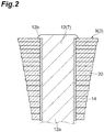
FIG. 2 is an enlarged sectional view illustrating a part of the motor illustrated inFIG. 1 . -
FIG. 3 is a perspective view illustrating a coil. -
FIG. 4 is a top view of the coil illustrated inFIG. 3 . -
FIG. 5 is a sectional view taken along line V-V ofFIG. 4 . -
FIG. 6 is a diagram illustrating waveforms of an induced electromotive force of the motor according to the present embodiment. -
FIG. 7 is a diagram illustrating waveforms of an induced electromotive force of a motor according to a comparative example. -
FIG. 8 is a view illustrating a modification of the motor. -
FIG. 9 is a diagram for illustrating a distortion factor. -
FIG. 10 is a diagram illustrating a relationship of motor efficiency to rotational frequency and torque of the motor according to the present embodiment. -
FIG. 11 is a diagram illustrating a relationship of motor efficiency to rotational frequency and torque of the motor according to the comparative example. -
FIG. 12 is a diagram illustrating motor efficiency and rate. - Hereinafter, a preferred embodiment of the present invention will be described in detail with reference to the attached drawings. In the description of the drawings, identical or equivalent elements are designated with the same reference signs, and duplicate description thereof will be omitted.
-
FIG. 1 is a view illustrating a motor according to an embodiment. As illustrated inFIG. 1 , a motor (a rotating electric machine) 1 is, for example, an outer rotor type of brushless motor (three-phase motor). Themotor 1 includes a stator (a coil device) 3 and arotor 5. - The
stator 3 has aniron core section 7 and coils 9. Theiron core section 7 has an annular part (a main body part) 10 with an annular shape, andcores 12. Theannular part 10 and thecores 12 are, for instance, formed in one body. Theannular part 10 and thecores 12 are formed, for instance, by stacking a plurality of electrical steel sheets. - As illustrated in
FIG. 2 , thecores 12 are provided to protrude outward from an outercircumferential surface 10a of theannular part 10 in a radial direction of theannular part 10. A plurality ofcores 12 are arranged at predetermined intervals in a circumferential direction of the outercircumferential surface 10a of theannular part 10. Thecores 12 have, for instance, a prismatic shape. A fan-like space S is defined between the two neighboringcores 12 by the twocores 12. - Each of the
cores 12 has amain body part 12a and aflange part 12b. Themain body part 12a extends in the radial direction of theannular part 10, and a base end side thereof is connected to theannular part 10. Theflange part 12b is provided at a tip portion of themain body part 12a in a longitudinal direction (an extending direction) of themain body part 12a. Theflange part 12b is projected outward from themain body part 12a in a width direction. -
FIG. 3 is a perspective view illustrating a coil.FIG. 4 is a top view of the coil illustrated inFIG. 3 .FIG. 5 is a sectional view taken along line V-V ofFIG. 4 . As illustrated inFIGS. 3 to 5 , each of thecoils 9 includes acoil section 20 andterminal parts coil section 20 and theterminal parts coil section 20 and theterminal parts FIG. 5 ) having conductivity. A material of theconductive member 21 is not particularly limited but, for instance, copper (Cu) may be used as the material. - The
coil section 20 is formed to be wound in a spiral shape. As illustrated inFIGS. 2 and3 , thecoil section 20 has a width dimension continuously increased from one side to the other side in a direction of an axis L of the coil section 20 (from a downward direction to an upward direction inFIG. 3 ). That is, when viewed in a direction along a plane orthogonal to the direction of the axis L, thecoil section 20 has an approximately trapezoidal shape. In thecoil section 20, a cross-sectional area of theconductive member 21 on a plane orthogonal to an extending direction of theconductive member 21 is uniform throughout the circumference of thecoil section 20. - An inner side of the
coil section 20 has a shape corresponding to a profile of each of thecores 12. In the present embodiment, each of thecores 12 has a rectangular (oblong) profile, and accordingly the inner side of thecoil section 20 has a rectangular (oblong) shape when viewed in the direction of the axis L of thecoil section 20 as illustrated inFIG. 4 . The shape of the inner side of thecoil section 20 may be properly set according to the profile of each of thecores 12. - The
coil section 20 having the above configuration is formed by joining a plurality ofconductive members 21. To be specific, thecoil section 20 is formed, for instance, by joining afirst portion 20a that extends linearly in an X-axial direction inFIGS. 3 and4 and asecond portion 20b that extends linearly in a Y-axial direction. For the junction between thefirst portion 20a and thesecond portion 20b, a method such as cold pressure welding, electric welding, high-frequency welding, brazing, or the like may be adopted. - As illustrated in
FIG. 5 , an insulatingfilm 24 is provided on anentire surface 21a of theconductive member 21 of thecoil section 20. The insulatingfilm 24 is a film (a portion) having an electrical insulation property. The insulatingfilm 24 is a synthetic resin having an electrical insulation property. The synthetic resin preferably includes a polyester resin, a polyurethane resin, an epoxy resin, a polyimide resin, a polyamide-imide resin, an esterimide resin, and so on. Particularly, from the viewpoint of heat resistance, the polyimide resin, the polyamide-imide resin, and the esterimide resin are preferred, and the polyimide resin is further preferred. To improve partial discharge resistance, it is further preferred that a filler be mixed with the insulatingfilm 24. The filler is not particularly limited, but an inorganic oxide such as silica, alumina, or boehmite alumina, a swellable clay such as smectite, a non-swelling clay such as talc or mica, or a layered double hydroxide such as hydrotalcite, etc. may be used. - For example, dip coating or electrodeposition coating may be used as a method for forming the insulating
film 24. After thecoil section 20 is formed, the insulatingfilm 24 is formed on each of theconductive members 21 of thecoil section 20. In detail, the insulatingfilm 24 is formed after thecoil section 20 is formed by joining thefirst portion 20a and thesecond portion 20b. - A thickness dimension of the insulating
film 24 is preferably greater than or equal to 10 µm, and more preferably greater than or equal to 10 µm and smaller than or equal to 50 µm. The thickness of the insulatingfilm 24 may be adequately set according to design of thecoil section 20. The thickness of the insulatingfilm 24 may be constant throughout the circumference of thecoil section 20, or be different in different portions of thecoil section 20. Dielectric breakdown voltage (withstand voltage) of the insulatingfilm 24 is preferably higher than or equal to 1 kV, for instance, when the thickness dimension is 10 µm, and higher than or equal to 4 kV, for instance, when the thickness dimension is 50 µm. The insulatingfilm 24 more preferably has heat resistance. - As illustrated in
FIG. 5 , in thecoil section 20,corners 21b of theconductive member 21 on which the insulatingfilm 24 is formed are chamfered. In the present embodiment, thecorners 21b are rounded. As a method of rounding thecorners 21b, a method of grinding thecorners 21b using, for instance, a mechanical, chemical, or electrical method may be used. Each of thecorners 21b of theconductive member 21 is not limited to a rounded shape, and may have a shape such as an angular face. It is only necessary that thecorner 21b of theconductive member 21 not be a shape in which faces forming thecorner 21b intersect each other approximately at right angles. - The
terminal parts coil section 20. Theconductive members 21 of the opposite ends of thecoil section 20 are lengthened, and thereby theterminal parts terminal parts coil section 20. - As illustrated in
FIG. 2 , thecoil 9 is mounted on thecore 12 by abobbin 14. Thebobbin 14 has a tubular shape. Thebobbin 14 is a member that has an electrical insulation property, and is formed of, for instance, nylon, nylon containing fiberglass, a polybutylene terephthalate resin, a polyethylene terephthalate resin, an ABS resin, a polyamide resin, a polyphenylene sulfide resin, a liquid crystal polyester resin, or the like. Thebobbin 14 is fitted around thecore 12, and an upper end thereof is seized by theflange part 12b of thecore 12. Thereby, thebobbin 14 is prevented from escaping from thecore 12. - As illustrated in
FIG. 2 , thecoil section 20 of thecoil 9 is mounted on the core 12 such that one side thereof having a small width dimension is located at the base end side of thecore 12. That is, the width dimension of thecoil section 20 gradually increases toward a tip side of thecore 12. Thereby, in thestator 3, a space factor of thecoil section 20 in the fan-like space S formed by the core 12 can be enhanced. In the present embodiment, the space factor is, for instance, higher than or equal to 90%. - The
rotor 5 is rotatably provided. Therotor 5 has amotor case 30 and a plurality ofmagnets 32. Themotor case 30 has a cylindrical shape. Themagnets 32 are disposed inside themotor case 30. To be specific, themagnets 32 are provided on an inner circumferential surface of themotor case 30 via a yoke (not shown), and are arranged in a circumferential direction of themotor case 30. To be more specific, themagnets 32 having different polarities are alternately arranged on the inner circumferential surface of themotor case 30. - In the
motor 1 having the above configuration, an electric current flows to thecoils 9, and thereby therotor 5 is rotated depending on a value of the electric current. - As described above, in the
motor 1 according to the present embodiment, thecores 12 are provided to protrude from the outercircumferential surface 10a of theannular part 10 in the radial direction of theannular part 10. In this configuration, a fan-like space S is defined between the neighboringcores 12. In this configuration, the width dimension of thecoil section 20 gradually increases from one side to the other side in the direction of the axis L of thecoil section 20. The one side of thecoil section 20 is arranged on the core 12 to be located at the base end side of thecore 12. With this configuration, since thecoil section 20 is arranged on the core such that the width thereof is widened toward the tip side of the core 12, a space factor of thecoil section 20 can be enhanced in the fan-like space S defined by thecores 12. The insulatingfilm 24 having an electrical insulation property is provided on thesurface 21a of theconductive member 21 of thecoil section 20. For this reason, the generation of creeping discharge or the like between theconductive members motor 1 having thecoils 9, the distortion of waveforms of an induced electromotive force generated by rotation can be suppressed. Therefore, in themotor 1, the generation of torque ripples can be suppressed, and the rotation of therotor 5 is made uniform. As a result, in themotor 1, the performance can be improved. - The performance of the
motor 1 will be concretely described.FIG. 6 is a diagram illustrating waveforms of an induced electromotive force of the motor according to the present embodiment.FIG. 7 is a diagram illustrating waveforms of an induced electromotive force of a motor according to a comparative example. The waveforms of the induced electromotive force shown inFIG. 6 are waveforms of amotor 1A shown inFIG. 8 . - First, the
motor 1A will be described.FIG. 8 is a view illustrating a modification of the motor. As illustrated inFIG. 8 , themotor 1A is an inner rotor type three-phase motor. Themotor 1A includes astator 3A and arotor 5A. Thestator 3A has aniron core section 7A and coils 9. Theiron core section 7A has anannular part 10A with an annular shape, andcores 12A. - The
cores 12A are provided to protrude inward from an inner circumferential surface 10Aa of theannular part 10A in a radial direction of theannular part 10A. A plurality ofcores 12A are arranged at predetermined intervals in a circumferential direction of the inner circumferential surface 10Aa of theannular part 10A. Thecores 12A have, for instance, prismatic shapes. A fan-like space S is defined between the two neighboringcores 12A by the twocores 12A. Thecoils 9 are arranged at thecores 12A by bobbins (not shown). Each of thecoils 9 is mounted on thecore 12A such that one side thereof having a great width dimension of thecoil section 20 is located at a base end side of thecore 12A. The number of turns of thecoil section 20 of thecoil 9 is set to "38." - The
rotor 5A has arotary body 30A and a plurality ofmagnets 32A. Therotary body 30A has a columnar shape. Themagnets 32A are disposed outside therotary body 30A. To be specific, themagnets 32A are provided on an outer circumferential surface of therotary body 30A via a yoke (not shown), and are arranged in a circumferential direction of therotary body 30A. To be more specific, themagnets 32A having different polarities are alternately arranged on the outer circumferential surface of therotary body 30A. - The waveforms of the induced electromotive force shown in
FIG. 7 are waveforms of the motor of the comparative example which includes coils formed by concentrically winding a round enamel wire. The motor of the comparative example has a coil configuration different from that of themotor 1A, and other configurations (cores, a rotor, etc.) identical to those of themotor 1A. The motor of the comparative example has coils formed by winding a round enamel wire around thecores 80 times. - In
FIGS. 6 and7 , (a) shows the waveforms of the induced electromotive force when a rotational frequency is 100 rpm, and (b) shows the waveforms of the induced electromotive force when a rotational frequency is 250 rpm. In themotor 1A and the motor of the comparative example, distortion factors when the rotational frequency is changed are represented in Table 1 below.[Table 1] Rotational frequency [rpm] Motor 1AMotor of comparative example Distortion factor [%] 100 4.6 14.8 150 4.7 10.9 250 3.0 5.2 - As illustrated in
FIGS. 6 and7 , the waveforms of the induced electromotive forces of themotor 1A and the motor of the comparative example, that is the waveforms of the induced electromotive forces generated when the motors are rotated, are approximate sine waves. Here, the sine wave is a waveform (a waveform indicated inFIG. 9 by a solid line) in which the distortion factor to be described below is 0%, and an approximate sine wave is a waveform that is extremely close to the sine wave or a waveform that is regarded as the sine wave. As shown in Table 1, in comparison with the waveforms of the induced electromotive force of the motor of the comparative example, the waveforms of the induced electromotive force of themotor 1A are small in the distortion factor from the sine wave even at any of 100 rpm, 150 rpm, and 250 rpm despite the fact that the number of turns in the coil is less than or equal to 1/2. Here, the distortion factor from the sine wave will be described with reference toFIG. 9 . - In the present embodiment, the distortion factor indicates a ratio of a harmonic component amplitude to a fundamental component amplitude at a peak point of the waveform of the induced electromotive force. As illustrated in
FIG. 9 , the fundamental component amplitude is an amplitude of a fundamental wave (a distortion-free sine wave). The harmonic component amplitude is an amplitude of a higher frequency component of the integral multiple of the fundamental wave. The distortion factor is obtained from the following expression. In Table 1, the distortion factors of all three of the phases are calculated on the basis of the following expression, and are averaged to calculate the distortion factor.
- As shown in Table 1, in the waveforms of the induced electromotive force of the motor of the comparative example, the distortion factor from the sine wave is 14.8% at 100 rpm, whereas in the waveforms of the induced electromotive force of the
motor 1A, the distortion factor from the sine wave is 4.6%. That is, the distortion factor from the sine wave at 100 rpm in the waveforms of the induced electromotive force of themotor 1A is about 1/3 of the distortion factor from the sine wave in the waveforms of the induced electromotive force of the motor of the comparative example. The distortion factor (3.0%) from the sine wave even at 250 rpm in the waveforms of the induced electromotive force of themotor 1A is smaller than the distortion factor (5.2%) from the sine wave in the waveforms of the induced electromotive force of the motor of the comparative example. That is, in comparison with the motor of the comparative example, themotor 1A according to the present embodiment is small in the distortion factor over a wide range from a case in which the rotational frequency is low to a case in which the rotational frequency is high. - In the
motor 1A according to the present embodiment, the distortion factor at a rotational frequency of 100 rpm is preferably less than or equal to 10%, and more preferably less than or equal to 5%. In themotor 1A, the distortion factor at a rotational frequency of 150 rpm is preferably less than or equal to 10%, and more preferably less than or equal to 5%. In addition, in themotor 1A, the distortion factor at a rotational frequency of 250 rpm is preferably less than or equal to 5%, and more preferably less than or equal to 3%. - In general, the motor has a smaller torque ripple in the case in which the distortion factor is small (the ratio of the harmonic component is small, and the distortion of the sine wave is small) than in the case in which the distortion factor is great (the ratio of the harmonic component is great, and the sine wave is distorted). For this reason, in the
motor 1A, it is confirmed that, in comparison with the coil configured by the concentrical winding of the enamel wire, a variation in torque caused by the torque ripple is small, and the rotation is smooth. Thereby, even in a low rotation region, therotor 5A is smoothly rotated. This result is similarly obtained in the motor 1 (the outer rotor type). -
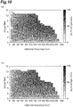
FIG. 10 is a diagram illustrating a relationship (hereinafter referred to as "efficiency map") of motor efficiency to rotational frequency and torque of themotor 1A according to the present embodiment.FIG. 11 is a diagram illustrating an efficiency map of the motor according to the comparative example. The efficiency maps shown inFIGS. 10 and11 are measured with a reducer connected to the motor. For this reason, in the efficiency maps shown inFIGS. 10 and11 , the rotational frequency of the motor is 1/4 times, and the torque is four times.FIGS. 10(a) and11(a) illustrate the efficiency map of a case measured at room temperature, andFIGS. 10(b) and11(b) illustrate the efficiency map of a case measured at a high temperature (60°C). -
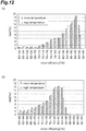
FIG. 12 is a diagram illustrating motor efficiency and rate. InFIG. 12 , to quantitatively evaluate the efficiency maps ofFIGS. 10 and11 , a value of the motor efficiency is shown in units of 2% and as a rate with respect to an entire measurement range.FIG. 12(a) shows results of themotor 1A, andFIG. 12(b) shows results of the motor of the comparative example. In Table 2, rates with respect to an entire driving range in which the motor efficiency is greater than or equal to 90% and a maximum efficiency are shown.[Table 2] Rate [%] with respect to entire driving range in which motor efficiency is greater than or equal to 90% Maximum efficiency [%] Room temperature High temperature Room temperature High temperature Motor 1A 13.6 7.6 92.0 91.6 Motor of comparative example 0.1 0 90.6 85.6 - As shown in
FIGS. 10 ,11 and12 and Table 2, themotor 1A has higher efficiency than the motor of the comparative example in a wide driving range. Further, even with regard to the rates and the maximum efficiency with respect to the entire driving range in which the motor efficiency is greater than or equal to 90% at a high temperature, themotor 1A is higher than the motor of the comparative example. - In general, the motor having high maximum efficiency as well as high efficiency in the wide driving range is obtained. It is found from the results shown in
FIGS. 10 ,11 and12 and Table 2 that themotor 1A is high in performance compared to the motor of the comparative example. - In the present embodiment, the insulating
film 24 is formed by dip coating or electrodeposition coating. Thereby, the insulatingfilm 24 can be formed well on thesurface 21a of theconductive member 21. - In the present embodiment, the
corners 21b of theconductive member 21 are chamfered. When thecorners 21b of theconductive member 21 are approximately right angles, it is difficult for the insulatingfilm 24 to be formed on thecorners 21b, and it is easy for the insulatingfilm 24 to peel off at thecorners 21b. The insulatingfilm 24 can be formed well even at thecorners 21b by chamfering thecorners 21b of theconductive member 21. Therefore, the insulation property can be even more secured in thecoil section 20. - In the present embodiment, the
coil section 20 is formed by joining the plurality ofconductive members 21. Thereby, a desired shape of thecoil section 20 can be easily formed. For this reason, the formation of a gap between the core 12 and thecoil section 20 can be suppressed. As a result, the space factor of thecoil 9 can be enhanced. - In the present embodiment, the cross-sectional area of the
conductive member 21 on the plane orthogonal to the extending direction of theconductive member 21 is uniform throughout the circumference of thecoil section 20. Thereby, a value of electrical resistance becomes constant in thecoil section 20. For this reason, the performance of thecoil 9 can be improved. - In the present embodiment, the insulating
film 24 has a thickness of 10 µm or more. Thereby, the insulation property between theconductive members 21 in thecoil section 20 can be secured, and the creeping discharge can be suppressed. - The present invention is not limited to the above embodiments. For example, in the above embodiments, the motor 1 (the
motor 1A) acting as the rotating electric machine has been described by way of example. However, the rotating electric machine may be, for instance, an electric generator or the like. - In the above embodiments, the configuration in which the cross-sectional area of the
conductive member 21 is uniform over the entirety of thecoil section 20 has been described by way of example. However, the cross-sectional area of theconductive member 21 is not necessarily uniform over the entirety. - In the above embodiments, the configuration in which the
motor FIG. 1 or8 has been described by way of example. However, the number ofcores magnets - In the above embodiments, the configuration in which the plurality of
conductive members 21 are joined to form thecoil 9 has been described by way of example. However, the method of forming thecoil 9 is not limited thereto. - In the above embodiments, the configuration in which the
coil section 20 is formed by joining thefirst portion 20a of a linear shape and thesecond portion 20b of a linear shape has been described by way of example. However, the formation of thecoil section 20 is not limited to the junction between the first andsecond portions coil section 20 may be formed by joining first and second portions having other shapes. - In the above embodiments, the configuration in which the
iron core section 7 has theannular part 10 of an annular shape has been described by way of example. However, the profile of the main body part may have a circular shape and, for instance, a disc shape. - In the above embodiments, the configuration in which the insulating
film 24 is formed by dip coating or electrodeposition coating has been described by way of example. However, the method of forming the insulatingfilm 24 is not limited thereto. - In the above embodiments, the configuration in which the
coil 9 is mounted on thebobbin 14 has been described by way of example. However, thebobbin 14 may not be provided. In this case, thecoil 9 is integrally molded by covering an outside of the insulatingfilm 24 with a resin. Thereby, thebobbin 14 can be omitted, and the coil device can be simplified. The resin used to mold thecoil 9 can be the same resin as thebobbin 14. Aside from the material of theaforementioned bobbin 14, thermosetting resins such as an epoxy resin or thermoplastic resins may be used. As the method of molding thecoil 9, an injection molding method or a powder fluidized bed dipping method may be used. -
- 1, 1A
- Motor (rotating electric machine, coil device)
- 7, 7A
- Iron core section
- 9
- Coil
- 10, 10A
- Annular part (main body part)
- 10a
- Outer circumferential surface (circumferential surface)
- 10Aa
- Inner circumferential surface (circumferential surface)
- 12, 12A
- Core
- 20
- Coil section
- 21
- Conductive member
- 21a
- Surface
- 21b
- Corner
- 22a, 22b
- Terminal part
- 24
- Insulating film
- L
- Axis
Claims (10)
- A rotating electric machine comprising:a stator having an iron core section with a main body part that has a circular circumferential surface and a plurality of cores that protrude from the circumferential surface of the main body part in a radial direction of the main body part and are provided at predetermined intervals in a circumferential direction of the circumferential surface, and coils arranged on the cores; anda rotor configured to rotate relative to the stator,wherein each of the coils includes a coil section that is formed in a spiral shape from a conductive member having conductivity, and terminal parts that are connected to opposite ends of the coil section,a width dimension of the coil section gradually increases from one side to the other side in a direction of an axis of the coil section, andan insulating film having an electrical insulation property is provided on a surface of the conductive member of the coil section.
- The rotating electric machine according to claim 1, wherein a waveform of an induced electromotive force generated by rotation is a sine wave or a quasi-sine wave.
- The rotating electric machine according to claim 1 or 2, wherein the rotating electric machine is an inner rotor type three-phase motor.
- A coil arranged on a core comprising:a coil section formed in a spiral shape from a conductive member having conductivity; andterminal parts connected to opposite ends of the coil section,wherein a width dimension of the coil section gradually increases from one side to the other side in a direction of an axis of the coil section, andan insulating film having an electrical insulation property is provided on a surface of the conductive member of the coil section.
- The coil according to claim 4, wherein the insulating film is formed by dip coating or electrodeposition coating.
- The coil according to claim 4 or 5, wherein the corners of the conductive member are chamfered.
- The coil according to any one of claims 4 to 6, wherein the coil section is formed by joining the numerous conductive members.
- The coil according to any one of claims 4 to 7, wherein a cross-sectional area of the conductive member on a plane orthogonal to an extending direction of the conductive member is uniform throughout a circumference of the coil section.
- The coil according to any one of claims 4 to 8, wherein the insulating film has a thickness of 10 µm or more.
- A coil device comprising:an iron core section having a main body part that has a circular circumferential surface and a plurality of cores that protrude from the circumferential surface of the main body part in a radial direction of the main body part and are provided at predetermined intervals in a circumferential direction of the circumferential surface; andcoils arranged on the cores,wherein each of the coils includes a coil section that is formed in a spiral shape from a conductive member having conductivity, and terminal parts that are connected to opposite ends of the coil section,a width dimension of the coil section gradually increases from one side to the other side in a direction of an axis of the coil section, andan insulating film having an electrical insulation property is provided on a surface of the conductive member of the coil section.
Applications Claiming Priority (2)
| Application Number | Priority Date | Filing Date | Title |
|---|---|---|---|
| JP2015023554 | 2015-02-09 | ||
| PCT/JP2016/053529 WO2016129525A1 (en) | 2015-02-09 | 2016-02-05 | Rotating electric machine, coil, and coil device |
Publications (2)
| Publication Number | Publication Date |
|---|---|
| EP3258574A1 true EP3258574A1 (en) | 2017-12-20 |
| EP3258574A4 EP3258574A4 (en) | 2018-09-12 |
Family
ID=56688522
Family Applications (1)
| Application Number | Title | Priority Date | Filing Date |
|---|---|---|---|
| EP16749169.5A Withdrawn EP3258574A4 (en) | 2015-02-09 | 2016-02-05 | Rotating electric machine, coil, and coil device |
Country Status (5)
| Country | Link |
|---|---|
| US (1) | US20180041087A1 (en) |
| EP (1) | EP3258574A4 (en) |
| JP (1) | JP2016149930A (en) |
| CN (1) | CN107210636A (en) |
| TW (1) | TW201637327A (en) |
Cited By (5)
| Publication number | Priority date | Publication date | Assignee | Title |
|---|---|---|---|---|
| CN108923703A (en) * | 2018-07-25 | 2018-11-30 | 江苏大学 | A kind of high efficient area moving method based on loss adjustment |
| EP3742587A4 (en) * | 2018-02-08 | 2021-10-13 | Aster Co., Ltd. | COIL UNIT, STATOR ELEMENT, STATOR, MOTOR AND MANUFACTURING PROCESS FOR COIL UNIT, STATOR ELEMENT, STATOR AND MOTOR |
| EP3863154A4 (en) * | 2018-10-02 | 2021-11-24 | Panasonic Intellectual Property Management Co., Ltd. | STATOR AND MOTOR USING IT |
| EP4383524A1 (en) * | 2022-12-07 | 2024-06-12 | Fukuta Electric & Machinery Co., Ltd. | Motor stator |
| WO2026057883A1 (en) | 2024-09-16 | 2026-03-19 | Sonceboz Mechatronics Boncourt Sa | Driving device that is easier to assemble |
Families Citing this family (10)
| Publication number | Priority date | Publication date | Assignee | Title |
|---|---|---|---|---|
| KR20180028454A (en) * | 2015-07-09 | 2018-03-16 | 스미토모 세이카 가부시키가이샤 | Electro Insulation Resin Composition |
| CN109478813B (en) * | 2017-01-27 | 2021-04-06 | 株式会社日立产机系统 | Axial Gap Type Rotary Electric Machine |
| JP7178558B2 (en) * | 2017-04-13 | 2022-11-28 | パナソニックIpマネジメント株式会社 | Coil and motor using it |
| TWI656712B (en) * | 2018-06-13 | 2019-04-11 | 東元電機股份有限公司 | Motor winding structure |
| WO2020080479A1 (en) * | 2018-10-18 | 2020-04-23 | パナソニックIpマネジメント株式会社 | Coil device |
| CN109378957B (en) * | 2018-12-22 | 2024-07-09 | 山东唐骏欧铃汽车制造有限公司 | Engine direct-drive flywheel type generator |
| DE102019202236A1 (en) * | 2019-02-19 | 2020-08-20 | Fraunhofer-Gesellschaft zur Förderung der angewandten Forschung e.V. | Method for producing a helical metal body |
| JP2020171096A (en) * | 2019-04-02 | 2020-10-15 | 株式会社Ihi | Stator |
| JP7334558B2 (en) * | 2019-09-25 | 2023-08-29 | 株式会社村田製作所 | inductor components |
| EP4383525A1 (en) * | 2022-12-09 | 2024-06-12 | Fukuta Electric & Machinery Co., Ltd. | Motor coil and motor stator |
Family Cites Families (6)
| Publication number | Priority date | Publication date | Assignee | Title |
|---|---|---|---|---|
| JP2006158024A (en) * | 2004-11-26 | 2006-06-15 | Sumitomo Electric Ind Ltd | Coil and manufacturing method thereof |
| JP2007295697A (en) * | 2006-04-24 | 2007-11-08 | Toyota Motor Corp | Rotating electrical machine stators and parts used for stators |
| JP5252807B2 (en) * | 2006-04-28 | 2013-07-31 | 三菱電線工業株式会社 | Linear member |
| EP2112744A1 (en) * | 2008-04-24 | 2009-10-28 | Magneti Marelli Holding S.p.A. | Multiphase synchronous electrical machine for converting kinetic energy into electrical energy and electrical energy into kinetic energy onboard a transport vehicle, and transport vehicle provided with said electrical machine |
| DK2362526T3 (en) * | 2010-02-26 | 2014-05-05 | Siemens Ag | Method of manufacturing a stator for an energy conversion device |
| DE102013212087C5 (en) * | 2013-06-25 | 2019-12-12 | Breuckmann GmbH & Co. KG | Method for producing a coil |
-
2016
- 2016-02-05 EP EP16749169.5A patent/EP3258574A4/en not_active Withdrawn
- 2016-02-05 CN CN201680009288.6A patent/CN107210636A/en active Pending
- 2016-02-05 JP JP2016020470A patent/JP2016149930A/en active Pending
- 2016-02-05 US US15/549,592 patent/US20180041087A1/en not_active Abandoned
- 2016-02-15 TW TW105104219A patent/TW201637327A/en unknown
Cited By (9)
| Publication number | Priority date | Publication date | Assignee | Title |
|---|---|---|---|---|
| EP3742587A4 (en) * | 2018-02-08 | 2021-10-13 | Aster Co., Ltd. | COIL UNIT, STATOR ELEMENT, STATOR, MOTOR AND MANUFACTURING PROCESS FOR COIL UNIT, STATOR ELEMENT, STATOR AND MOTOR |
| US12199483B2 (en) | 2018-02-08 | 2025-01-14 | Aster Co., Ltd. | Coil unit, stator member, stator, motor, and manufacturing method for coil unit, stator member, stator, and motor |
| CN108923703A (en) * | 2018-07-25 | 2018-11-30 | 江苏大学 | A kind of high efficient area moving method based on loss adjustment |
| CN108923703B (en) * | 2018-07-25 | 2021-07-20 | 江苏大学 | A Loss Adjustment-Based High Efficiency Zone Movement Method |
| EP3863154A4 (en) * | 2018-10-02 | 2021-11-24 | Panasonic Intellectual Property Management Co., Ltd. | STATOR AND MOTOR USING IT |
| US12095325B2 (en) | 2018-10-02 | 2024-09-17 | Panasonic Intellectual Property Management Co., Ltd. | Stator and motor using same |
| EP4383524A1 (en) * | 2022-12-07 | 2024-06-12 | Fukuta Electric & Machinery Co., Ltd. | Motor stator |
| WO2026057883A1 (en) | 2024-09-16 | 2026-03-19 | Sonceboz Mechatronics Boncourt Sa | Driving device that is easier to assemble |
| FR3166497A1 (en) * | 2024-09-16 | 2026-03-20 | Sonceboz Mechatronics Boncourt Sa | Easy-to-assemble training device |
Also Published As
| Publication number | Publication date |
|---|---|
| CN107210636A (en) | 2017-09-26 |
| US20180041087A1 (en) | 2018-02-08 |
| EP3258574A4 (en) | 2018-09-12 |
| JP2016149930A (en) | 2016-08-18 |
| TW201637327A (en) | 2016-10-16 |
Similar Documents
| Publication | Publication Date | Title |
|---|---|---|
| US20180041087A1 (en) | Rotating electric machine, coil, and coil device | |
| US11075556B2 (en) | Coreless electric machine with magnet coils with effective coil part and end coil parts | |
| US8614617B2 (en) | Reactor | |
| CN103929000B (en) | Set wire and electric rotating machine for electric rotating machine winding | |
| US11152828B2 (en) | Rotating electric machine | |
| JP5214064B2 (en) | Inverter integrated drive module | |
| US11063486B2 (en) | Coreless electric machine with magnet coils having trapezoidal shape and angle less than 90 degrees with circumferentially aligned legs | |
| US20170237304A1 (en) | Stator for rotary electric machine | |
| JP2013215021A (en) | Electromagnetic induction device | |
| WO2018190124A1 (en) | Coil and motor using same | |
| CN113039704A (en) | Stator and motor using the same | |
| JP5399317B2 (en) | Reactor | |
| JP2015223028A (en) | Stator for rotary electric machine | |
| KR20160086698A (en) | Stator assembly of Motor | |
| JP6415029B2 (en) | Electromagnetic induction device | |
| KR102342560B1 (en) | Stator for rotary electric machine | |
| US10840015B2 (en) | Laminated core rotatable transformer | |
| CN112789785B (en) | Claw pole motor with toroidal coils and zigzag coils | |
| JP2014054092A (en) | Axial-gap brushless motor | |
| US20230208238A1 (en) | Electric drive for a vehicle | |
| JP6394542B2 (en) | Rotating electrical machine stator | |
| WO2016129525A1 (en) | Rotating electric machine, coil, and coil device | |
| JP2015082952A (en) | Stator for rotary electric machine and method for forming insulation film of coil | |
| US20200136457A1 (en) | Stator of rotating electric apparatus | |
| JP2015119535A (en) | Rotary electric machine stator |
Legal Events
| Date | Code | Title | Description |
|---|---|---|---|
| PUAI | Public reference made under article 153(3) epc to a published international application that has entered the european phase |
Free format text: ORIGINAL CODE: 0009012 |
|
| 17P | Request for examination filed |
Effective date: 20170905 |
|
| AK | Designated contracting states |
Kind code of ref document: A1 Designated state(s): AL AT BE BG CH CY CZ DE DK EE ES FI FR GB GR HR HU IE IS IT LI LT LU LV MC MK MT NL NO PL PT RO RS SE SI SK SM TR |
|
| AX | Request for extension of the european patent |
Extension state: BA ME |
|
| DAV | Request for validation of the european patent (deleted) | ||
| DAX | Request for extension of the european patent (deleted) | ||
| RIC1 | Information provided on ipc code assigned before grant |
Ipc: H02K 1/14 20060101ALN20180802BHEP Ipc: H02K 3/34 20060101ALN20180802BHEP Ipc: H02K 15/04 20060101ALI20180802BHEP Ipc: H02K 29/03 20060101ALN20180802BHEP Ipc: H02K 3/18 20060101AFI20180802BHEP Ipc: H02K 21/16 20060101ALN20180802BHEP Ipc: H02K 1/27 20060101ALN20180802BHEP |
|
| A4 | Supplementary search report drawn up and despatched |
Effective date: 20180809 |
|
| STAA | Information on the status of an ep patent application or granted ep patent |
Free format text: STATUS: THE APPLICATION IS DEEMED TO BE WITHDRAWN |
|
| 18D | Application deemed to be withdrawn |
Effective date: 20190308 |