EP3258567A1 - Self-loop detection method and apparatus for charging device - Google Patents
Self-loop detection method and apparatus for charging device Download PDFInfo
- Publication number
- EP3258567A1 EP3258567A1 EP15884237.7A EP15884237A EP3258567A1 EP 3258567 A1 EP3258567 A1 EP 3258567A1 EP 15884237 A EP15884237 A EP 15884237A EP 3258567 A1 EP3258567 A1 EP 3258567A1
- Authority
- EP
- European Patent Office
- Prior art keywords
- charging
- outbound
- inbound
- charging interface
- self
- Prior art date
- Legal status (The legal status is an assumption and is not a legal conclusion. Google has not performed a legal analysis and makes no representation as to the accuracy of the status listed.)
- Granted
Links
Images


Classifications
-
- H—ELECTRICITY
- H02—GENERATION; CONVERSION OR DISTRIBUTION OF ELECTRIC POWER
- H02J—ELECTRIC POWER NETWORKS; CIRCUIT ARRANGEMENTS OR SYSTEMS FOR SUPPLYING OR DISTRIBUTING ELECTRIC POWER; SYSTEMS FOR STORING ELECTRIC ENERGY
- H02J7/00—Circuit arrangements for charging or discharging batteries or for supplying loads from batteries
-
- H—ELECTRICITY
- H02—GENERATION; CONVERSION OR DISTRIBUTION OF ELECTRIC POWER
- H02J—ELECTRIC POWER NETWORKS; CIRCUIT ARRANGEMENTS OR SYSTEMS FOR SUPPLYING OR DISTRIBUTING ELECTRIC POWER; SYSTEMS FOR STORING ELECTRIC ENERGY
- H02J7/00—Circuit arrangements for charging or discharging batteries or for supplying loads from batteries
- H02J7/60—Circuit arrangements for charging or discharging batteries or for supplying loads from batteries including safety or protection arrangements
- H02J7/685—Circuit arrangements for charging or discharging batteries or for supplying loads from batteries including safety or protection arrangements using connection detecting circuits
-
- H—ELECTRICITY
- H02—GENERATION; CONVERSION OR DISTRIBUTION OF ELECTRIC POWER
- H02J—ELECTRIC POWER NETWORKS; CIRCUIT ARRANGEMENTS OR SYSTEMS FOR SUPPLYING OR DISTRIBUTING ELECTRIC POWER; SYSTEMS FOR STORING ELECTRIC ENERGY
- H02J7/00—Circuit arrangements for charging or discharging batteries or for supplying loads from batteries
- H02J7/02—Circuit arrangements for charging or discharging batteries or for supplying loads from batteries for charging batteries from AC mains by converters
- H02J7/04—Regulation of charging current or voltage
-
- H—ELECTRICITY
- H02—GENERATION; CONVERSION OR DISTRIBUTION OF ELECTRIC POWER
- H02J—ELECTRIC POWER NETWORKS; CIRCUIT ARRANGEMENTS OR SYSTEMS FOR SUPPLYING OR DISTRIBUTING ELECTRIC POWER; SYSTEMS FOR STORING ELECTRIC ENERGY
- H02J7/00—Circuit arrangements for charging or discharging batteries or for supplying loads from batteries
- H02J7/80—Circuit arrangements for charging or discharging batteries or for supplying loads from batteries including monitoring or indicating arrangements
Definitions
- the present invention relates to the field of circuit technologies, and in particular, to a self-loop detection method and apparatus for a charging device.
- a mobile power supply 1 includes a large-capacity battery 10, a power supply management circuit 11, an inbound charging interface 12, an outbound charging interface 13, and the like.
- the inbound charging interface 12 is used by an external battery charger to charge the mobile power supply 1.
- the outbound charging interface 13 is used by the mobile power supply 1 to charge an external device (such as a tablet computer or a mobile phone).
- the mobile power supply preferably can perform inbound charging and outbound charging at the same time, so that a user can conveniently use the mobile power supply.
- some users may directly connect the inbound charging interface 12 to the outbound charging interface 13.
- a current loop (the current loop is referred to as a self-loop below) is formed in the mobile power supply 1. Consequently, electric energy of the mobile power supply 1 is consumed in vain.
- the inbound charging interface 12 and the outbound charging interface 13 are connected for an excessively long time, excessive heat of the mobile power supply 1 may even damage an internal circuit of the mobile power supply 1.
- Embodiments of the present invention provide a self-loop detection method and apparatus for a charging device, so as to detect, when the charging device performs inbound charging and outbound charging at the same time, whether a self-loop exists in the charging device.
- a self-loop detection method for a charging device includes an inbound charging interface and an outbound charging interface, where the inbound charging interface includes a positive signal cable D; and a negative signal cable D i , the outbound charging interface includes a positive signal cable D o and a negative signal cable D o , the inbound charging interface is in an inbound charging state, and the outbound charging interface is in an outbound charging state; and the method includes:
- the method further includes:
- the method further includes:
- the method further includes:
- the determining whether the self-loop of the charging device is eliminated includes:
- a self-loop detection method for a charging device where the charging device includes an inbound charging interface and an outbound charging interface; and the method includes:
- the method further includes:
- a self-loop detection apparatus for a charging device includes an inbound charging interface and an outbound charging interface, where the inbound charging interface includes a positive signal cable D i and a negative signal cable D i , the outbound charging interface includes a positive signal cable D o and a negative signal cable D o , the inbound charging interface is in an inbound charging state, and the outbound charging interface is in an outbound charging state; and the apparatus includes:
- the apparatus further includes:
- the apparatus further includes:
- the determining unit is further configured to determine whether the self-loop of the charging device is eliminated; and the control unit is further configured to: when the determining unit determines that the self-loop of the charging device is not eliminated, control the outbound charging interface to enter an outbound charging stop state; or control the inbound charging interface to enter an inbound charging stop state; or control a value of a current flowing into the inbound charging interface, so that the current value is less than a maximum current value that exists when the self-loop exists in the charging device.
- the detection unit is further configured to: detect whether a connection cable is removed from the outbound charging interface and/or detect whether a connection cable is removed from the inbound charging interface; and the determining unit is further configured to: when the detection unit detects that the connection cable is removed from the outbound charging interface and/or detects that the connection cable is removed from the inbound charging interface, determine that the self-loop of the charging device is eliminated.
- a self-loop detection apparatus for a charging device where the charging device includes an inbound charging interface and an outbound charging interface; and the apparatus includes:
- the apparatus further includes:
- a self-loop detection apparatus for a charging device includes an inbound charging interface and an outbound charging interface, where the inbound charging interface includes a positive signal cable D i and a negative signal cable D i , the outbound charging interface includes a positive signal cable D o and a negative signal cable D o , the inbound charging interface is in an inbound charging state, and the outbound charging interface is in an outbound charging state; and the apparatus includes: a memory and a processor, where the memory is configured to store a set of code, and the code is used to control the processor to perform the following operations:
- the processor is further configured to:
- the processor is further configured to:
- the processor is further configured to:
- the processor is further configured to:
- a self-loop detection apparatus for a charging device, where the charging device includes an inbound charging interface and an outbound charging interface; and the apparatus includes: a memory and a processor, where the memory is configured to store a set of code, and the code is used to control the processor to perform the following operations:
- the processor is further configured to: output a prompt message, where the prompt message is used to remind a user that a self-loop exists in the charging device when the outbound charging interface is in the outbound charging state again.
- the self-loop detection method and apparatus for a charging device when an outbound charging interface is in an outbound charging state, an inbound charging interface is in an inbound charging state, and a positive signal cable D i is connected to a negative signal cable D i , whether a self-loop exists in the charging device is detected.
- a positive signal cable D o of the outbound charging interface and a negative signal cable D o of the outbound charging interface are switched from a connected state to a disconnected state
- the positive signal cable D i of the inbound charging interface and the negative signal cable D i of the inbound charging interface are also switched from a connected state to a disconnected state. Therefore, it may be detected, according to this feature, that the self-loop exists in the charging device.
- the charging device includes an inbound charging interface and an outbound charging interface.
- the inbound charging interface includes a positive signal cable D i and a negative signal cable D i .
- the outbound charging interface includes a positive signal cable D o and a negative signal cable D o .
- the inbound charging interface is in an inbound charging state, and the outbound charging interface is in an outbound charging state.
- the method includes the following steps.
- the charging device in this embodiment of the present invention may charge an external device (such as a mobile phone or a tablet computer), and an external battery charger may also charge the charging device.
- the charging device may be a mobile power supply, or may be another device having the foregoing function.
- This embodiment of the present invention may be executed by the charging device, or may be a detection device that may implement the foregoing method. This is not limited in this embodiment of the present invention. An example of the technical solution provided in this embodiment of the present invention is described, and this embodiment of the present invention is executed, for example, by a detection device.
- a charging device 3 includes an inbound charging interface 31 and an outbound charging interface 32.
- the inbound charging interface 31 and the outbound charging interface 32 both include a positive signal cable D (may also be represented as "D+") and a negative signal cable D (may also be represented as "D-").
- the positive signal cable D of the inbound charging interface 31 is represented as a positive signal cable D i (represented as D i + in FIG. 3 )
- the negative signal cable D of the inbound charging interface 31 is represented as a negative signal cable D i (represented as D i - in FIG. 3 ).
- the positive signal cable D of the outbound charging interface 32 is represented as a positive signal cable D o (represented as D o + in FIG. 3 ), and the negative signal cable D of the outbound charging interface 32 is represented as a negative signal cable D o (represented as D o - in FIG. 3 ).
- the inbound charging interface 31 and the outbound charging interface 32 both include a power cable (both are represented as V in FIG. 3 ) and a ground cable (both are represented as G in FIG. 3 ).
- the inbound charging interface 31 and the outbound charging interface 32 are connected to a same ground cable.
- the charging device 3 may further include a large-capacity battery, a power supply management circuit, and the like (not shown in FIG. 3 ).
- a switch may be disposed between the positive signal cable D o and the negative signal cable D o .
- the detection device may control, by using the switch, the positive signal cable D o and the negative signal cable D o to connect to or disconnect from each other.
- the outbound charging interface of the charging device is still in the outbound charging state, that is, the power cable of the outbound charging interface is in a power supplying state.
- connection cable connecting the external battery charger to the inbound charging interface of the charging device includes power cables, ground cables, positive signal cable Ds, and negative signal cable Ds corresponding to the external battery charger and the inbound charging interface.
- the positive signal cable D and the negative signal cable D of the external battery charger are respectively marked as D n + and D n -.
- D n + is connected to D n -
- D i + is also connected to D i -, so as to form a loop that passes through D n +, D n -, D i -, and D i +, and finally goes back to D n +.
- D n + is not connected to D n -
- D i + is not connected to D i - either. Therefore, the charging device may determine, by detecting whether D i - is connected to D i +, whether the external battery charger is a standard battery charger.
- the external device may also detect, by using the foregoing method, whether the charging device is a standard battery charger.
- the charging device when an external battery charger charges the charging device, the charging device does not limit a magnitude of a current flowing into the charging device if identifying that the external battery charger is a standard battery charger; and the charging device limits a magnitude of a current flowing into the charging device if identifying that the external battery charger is a non-standard battery charger.
- the charging device identifies, only when charging just starts, whether an external battery charger is a standard battery charger. This same principle applies when the charging device charges an external device.
- the positive signal cable D o is connected to the negative signal cable D o . Therefore, if a self-loop exists in the charging device, the positive signal cable D i is connected to the negative signal cable D i .
- the positive signal cable D i and the negative signal cable D i are also switched from the connected state to the disconnected state. Therefore, whether the self-loop exists in the charging device may be detected according to this feature.
- Table 1 uses a table (Table 1) to more clearly describe correspondences among a state between the positive signal cable D i and the negative signal cable D i (the state is connected or disconnected), whether a self-loop exists in a power supply device, and whether the positive signal cable D i and the negative signal cable D i are switched from the connected state to the disconnected state (referred to as "whether a switchover is performed" in the table), before or after the detection device performs step 201 when the inbound charging interface is in different states.
- Table 1 uses a table (Table 1) to more clearly describe correspondences among a state between the positive signal cable D i and the negative signal cable D i (the state is connected or disconnected), whether a self-loop exists in a power supply device, and whether the positive signal cable D i and the negative signal cable D i are switched from the connected state to the disconnected state (referred to as "whether a switchover is performed" in the table), before or after the detection device performs step 201 when the inbound charging interface is in different states.
- a state between the positive signal cable D i and the negative signal cable D i before step 201 is referred to as an A state
- a state between the positive signal cable D i and the negative signal cable D i after step 201 is referred to as a B state.
- Table 1 Working state of an inbound charging interface Whether a self-loop exists in a power supply device A state B state Whether a switchover is performed Inbound working stop state No Disconnected Disconnected No Inbound working state (connected to a standard battery charger) No Connected Connected No Inbound working state (connected to a non-standard battery charger) No Disconnected Disconnected No Inbound working state (connected to an outbound charging interface) Yes Connected Disconnected Yes
- the detection device may determine, by detecting whether the positive signal cable D i and the negative signal cable D i are switched between the connected state and the disconnected state, whether a self-loop exists in the charging device.
- the positive signal cable D o and the negative signal cable D o of the charging device may be restored to a short-circuit state.
- the method may further include:
- the detection device controls the outbound charging interface to enter the outbound charging stop state or controls the inbound charging interface to enter the inbound charging stop state, the self-loop existing in the charging device is eliminated.
- the detection device controls the value of the current flowing into the inbound charging interface, the self-loop still exists in the charging device. However, because the current value is less than the maximum current value that exists when the self-loop exists in the charging device, electric energy consumption caused because the self-loop exists in the charging device may be reduced. In addition, a smaller current value is better. This is because a smaller current value indicates smaller electric energy consumption caused because the self-loop exists in the charging device. It should be noted that because the charging device identifies at the beginning that an external battery charger (when a self-loop exists in the charging device, the charging device charges itself) that charges the charging device is a standard battery charger, a magnitude of a current flowing into the charging device is not limited. When a self-loop exists in the charging device, the detection device controls a value of a current flowing into the inbound charging interface.
- the detection device when the detection device detects that a self-loop exists in the charging device, the detection device may output a control message to a power supply management circuit in the charging device.
- the power supply management circuit controls an internal circuit of the power supply management circuit according to the control message, so as to control a state of the inbound charging interface or the outbound charging interface.
- the method may further include: outputting a prompt message.
- the prompt message is used to remind a user that the self-loop exists in the charging device.
- the detection device may remind a user by turning on or turning off an indicator or displaying a digit/word on a screen.
- the detection device may also remind the user by sending a message to a device such as a mobile phone of the user. This is not limited in this embodiment of the present invention.
- the user may manually eliminate the self-loop. Specifically, the self-loop of the charging device may be eliminated by removing a connection cable from the inbound charging interface and/or the outbound charging interface of the charging device.
- the method further includes:
- the determining whether the self-loop of the charging device is eliminated includes: detecting whether a connection cable is removed from the outbound charging interface and/or detecting whether a connection cable is removed from the inbound charging interface; and if the connection cable is removed, determining that the self-loop of the charging device is eliminated.
- the detection device may detect whether a voltage of the power cable of the inbound charging interface is zero, and if the voltage of the power cable of the inbound charging interface is zero, the detection device determines that the connection cable is removed from the inbound charging interface.
- the detection device may detect this case. If the detection device detects this case within a particular time period after the detection device outputs the prompt message, it may be determined that the self-loop of the charging device is eliminated. If the detection device does not detect this case within a particular time period after the detection device outputs the prompt message, it may be determined that the self-loop of the charging device is not eliminated.
- connection cable when the outbound charging interface is in the outbound charging stop state, the connection cable is not removed from the outbound charging interface; and when the inbound charging interface is in the inbound charging stop state, the connection cable is not removed from the inbound charging interface either.
- a condition that triggers the outbound charging interface to be in the outbound charging state again may be that: a user manually performs setting, or the connection cable on the outbound charging interface is connected to the outbound charging interface again, or the connection cable on the inbound charging interface is connected to the inbound charging interface again.
- the self-loop detection method for a charging device when an outbound charging interface is in an outbound charging state, an inbound charging interface is in an inbound charging state, and a positive signal cable D i is connected to a negative signal cable D i , whether a self-loop exists in the charging device is detected.
- a positive signal cable D o of the outbound charging interface and a negative signal cable D o of the outbound charging interface are switched from a connected state to a disconnected state
- the positive signal cable D i of the inbound charging interface and the negative signal cable D i of the inbound charging interface are also switched from a connected state to a disconnected state. Therefore, it may be detected, according to this feature, that the self-loop exists in the charging device.
- the self-loop detection method for a charging device includes the following steps.
- An outbound charging interface of a charging device is in an outbound charging state.
- a positive signal cable D o of the outbound charging interface is connected to a negative signal cable D o of the outbound charging interface.
- a switch may be disposed between the positive signal cable D o and the negative signal cable D o .
- a detection device may control, by using the switch, the positive signal cable D o and the negative signal cable D o to connect to or disconnect from each other.
- step 403 If yes, perform step 403; and if not, perform step 407.
- the detection device detects that there is a voltage on a power cable of the inbound charging interface, it is considered that the inbound charging interface is in the inbound charging state.
- step 404 If yes, perform step 404; and if not, perform step 407.
- the positive signal cable D o of the outbound charging interface is connected to the negative signal cable D o of the outbound charging interface, when a self-loop exists in the charging device, the positive signal cable D i of the inbound charging interface is connected to the negative signal cable D i of the inbound charging interface.
- a condition that triggers the detection device to detect whether a self-loop exists in the charging device is that: the outbound charging interface is in the outbound charging state, the inbound charging interface is in the inbound charging state, and the positive signal cable D i is connected to the negative signal cable D i .
- step 407 If yes, it is determined that a self-loop exists in the charging device, and perform step 406. If not, perform step 407.
- the self-loop detection method for a charging device when an outbound charging interface is in an outbound charging state, an inbound charging interface is in an inbound charging state, and a positive signal cable D i is connected to a negative signal cable D i , whether a self-loop exists in the charging device is detected.
- a positive signal cable D o of the outbound charging interface and a negative signal cable D o of the outbound charging interface are switched from a connected state to a disconnected state
- the positive signal cable D i of the inbound charging interface and the negative signal cable D i of the inbound charging interface are also switched from a connected state to a disconnected state. Therefore, it may be detected, according to this feature, that the self-loop exists in the charging device.
- This embodiment of the present invention provides a self-loop detection method for a charging device.
- the charging device includes an inbound charging interface and an outbound charging interface. As shown in FIG. 5 , the method includes the following steps.
- a detection device may start to detect whether a self-loop exists in the charging device.
- the inbound charging interface and the outbound charging interface of the charging device are connected to each other. Therefore, when the outbound charging interface is switched from the outbound charging state to the outbound charging stop state, the inbound charging interface is naturally switched from the inbound charging state to the inbound charging stop state. Therefore, whether the self-loop exists in the charging device may be detected according to this feature.
- step 501 the detection device has eliminated the self-loop from the charging device.
- a connection cable that connects the inbound charging interface and the outbound charging interface of the charging device is not removed. Therefore, the self-loop still exists when the charging device is started at a next time.
- the method may further include: outputting a prompt message.
- the prompt message is used to remind a user that a self-loop exists in the charging device when the outbound charging interface is in the outbound charging state again.
- a user may remove the connection cable that is connected to the inbound charging interface and/or the outbound charging interface of the charging device, so as to avoid that the self-loop still exists in the charging device when the charging device is started at a next time.
- a condition that triggers the outbound charging interface to be in the outbound charging state again may be that: a user manually performs setting, or the connection cable on the outbound charging interface is connected to the outbound charging interface again, or the connection cable on the inbound charging interface is connected to the inbound charging interface again.
- a detection device may determine, according to this feature, whether the self-loop exists in the charging device.
- This embodiment of the present invention provides a self-loop detection apparatus 60 for a charging device, to execute the self-loop detection method for a charging device shown in FIG. 2 .
- the apparatus 60 includes: a switching unit 601, a detection unit 602, and a determining unit 603.
- the switching unit 601 is configured to switch the positive signal cable D o and the negative signal cable D o from a connected state to a disconnected state.
- the detection unit 602 is configured to detect whether the positive signal cable Di and the negative signal cable Di are switched from a connected state to a disconnected state.
- the determining unit 603 is configured to: when the detection unit 602 detects that the positive signal cable Di and the negative signal cable Di are switched from the connected state to the disconnected state, determine that a self-loop exists in the charging device.
- the apparatus 60 further includes:
- the apparatus 60 further includes an output unit 605, configured to output a prompt message.
- the prompt message is used to remind a user that the self-loop exists in the charging device.
- the determining unit 603 is further configured to determine whether the self-loop of the charging device is eliminated; and the control unit 604 is further configured to: when the determining unit 603 determines that the self-loop of the charging device is not eliminated, control the outbound charging interface to enter an outbound charging stop state; or control the inbound charging interface to enter an inbound charging stop state; or control a value of a current flowing into the inbound charging interface, so that the current value is less than a maximum current value that exists when the self-loop exists in the charging device.
- the detection unit 602 is further configured to: detect whether a connection cable is removed from the outbound charging interface and/or detect whether a connection cable is removed from the inbound charging interface; and the determining unit 603 is further configured to: when the detection unit 602 detects that the connection cable is removed from the outbound charging interface and/or detects that the connection cable is removed from the inbound charging interface, determine that the self-loop of the charging device is eliminated.
- the self-loop detection apparatus for a charging device when an outbound charging interface of the charging device is in an outbound charging state, an inbound charging interface of the charging device is in an inbound charging state, and a positive signal cable D i is connected to a negative signal cable D i , whether a self-loop exists in the charging device is detected.
- a positive signal cable D o of the outbound charging interface and a negative signal cable D o of the outbound charging interface are switched from a connected state to a disconnected state
- the positive signal cable D i of the inbound charging interface and the negative signal cable D i of the inbound charging interface are also switched from a connected state to a disconnected state. Therefore, it may be detected, according to this feature, that the self-loop exists in the charging device.
- the units in Embodiment 4 may be built in or independent of a processor of the self-loop detection apparatus for a charging device in a form of hardware, or may be stored in a memory of the self-loop detection apparatus for a charging device in a form of software, so as to be invoked by the processor to perform operations corresponding to the foregoing units.
- the processor may be a central processing unit (CPU for short), a microprocessor, a single-chip microcomputer, and the like.
- FIG. 8 shows a self-loop detection apparatus 80 for a charging device according to an embodiment of the present invention, to execute the self-loop detection method for a charging device shown in FIG. 2 .
- the apparatus 80 includes: a memory 801, a processor 802, and a bus system 803.
- the memory 801 and the processor 802 are coupled together by using the bus system 803.
- the bus system 803 may further include a power supply bus, a control bus, a state signal bus, and the like.
- various types of buses are all marked as the bus system 803 in the figure.
- the memory 801 is configured to store a set of code, and the code is used to control the processor 802 to perform the following operations:
- processor 802 is further configured to:
- the processor 802 is further configured to: output a prompt message.
- the prompt message is used to remind a user that the self-loop exists in the charging device.
- the processor 802 is further configured to: determine whether the self-loop of the charging device is eliminated; and when it is determined that the self-loop of the charging device is not eliminated, control the outbound charging interface to enter an outbound charging stop state; or control the inbound charging interface to enter an inbound charging stop state; or control a value of a current flowing into the inbound charging interface, so that the current value is less than a maximum current value that exists when the self-loop exists in the charging device.
- the processor 802 is further configured to: detect whether a connection cable is removed from the outbound charging interface and/or detect whether a connection cable is removed from the inbound charging interface; and when it is detected that the connection cable is removed from the outbound charging interface and/or it is detected that the connection cable is removed from the inbound charging interface, determine that the self-loop of the charging device is eliminated.
- the self-loop detection apparatus for a charging device when an outbound charging interface of the charging device is in an outbound charging state, an inbound charging interface of the charging device is in an inbound charging state, and a positive signal cable D i is connected to a negative signal cable D i , whether a self-loop exists in the charging device is detected.
- a positive signal cable D o of the outbound charging interface and a negative signal cable D o of the outbound charging interface are switched from a connected state to a disconnected state
- the positive signal cable D i of the inbound charging interface and the negative signal cable D i of the inbound charging interface are also switched from a connected state to a disconnected state. Therefore, it may be detected, according to this feature, that the self-loop exists in the charging device.
- This embodiment of the present invention provides a self-loop detection apparatus 90 for a charging device, to execute the self-loop detection method for a charging device shown in FIG. 5 .
- the apparatus 90 includes: a switching unit 901, a detection unit 902, and a determining unit 903.
- the switching unit 901 is configured to switch the outbound charging interface from an outbound charging state to an outbound charging stop state.
- the detection unit 902 is configured to detect whether the inbound charging interface is switched from an inbound charging state to an inbound charging stop state.
- the determining unit 903 is configured to: when the detection unit 902 detects that the inbound charging interface is switched from the inbound charging state to the inbound charging stop state, determine that a self-loop exists in the charging device when the outbound charging interface is in the outbound charging state.
- the apparatus 90 further includes:
- the self-loop detection apparatus for a charging device when a self-loop exists in the charging device, an inbound charging interface and an outbound charging interface of the charging device are connected to each other. Therefore, when the outbound charging interface is switched from an outbound charging state to an outbound charging stop state, the inbound charging interface is naturally switched from an inbound charging state to an inbound charging stop state. Therefore, the detection apparatus may determine, according to this feature, whether the self-loop exists in the charging device.
- the units in Embodiment 6 may be built in or independent of a processor of the self-loop detection apparatus for a charging device in a form of hardware, or may be stored in a memory of the self-loop detection apparatus for a charging device in a form of software, so as to be invoked by the processor to perform operations corresponding to the foregoing units.
- the processor may be a central processing unit (CPU for short), a microprocessor, a single-chip microcomputer, and the like.
- FIG. 11 shows a self-loop detection apparatus 110 for a charging device according to an embodiment of the present invention, to execute the self-loop detection method for a charging device shown in FIG. 5 .
- the apparatus 110 includes: a memory 1101, a processor 1102, and a bus system 1103.
- the memory 1101 and the processor 1102 are coupled together by using the bus system 1103.
- the bus system 1103 may further include a power bus, a control bus, a status signal bus, and the like.
- various types of buses are all marked as the bus system 1103 in the figure.
- the memory 1101 is configured to store a set of code, and the code is used to control the processor 1102 to perform the following operations:
- the processor 1102 is further configured to output a prompt message.
- the prompt message is used to remind a user that a self-loop exists in the charging device when the outbound charging interface is in the outbound charging state again.
- the self-loop detection apparatus for a charging device when a self-loop exists in the charging device, an inbound charging interface and an outbound charging interface of the charging device are connected to each other. Therefore, when the outbound charging interface is switched from an outbound charging state to an outbound charging stop state, the inbound charging interface is naturally switched from an inbound charging state to an inbound charging stop state. Therefore, the detection apparatus may determine, according to this feature, whether the self-loop exists in the charging device.
- the disclosed apparatus and method may be implemented in other manners.
- the described apparatus embodiment is merely an example.
- the unit division is merely logical function division and may be other division in actual implementation.
- a plurality of units or components may be combined or integrated into another system, or some features may be ignored or not performed.
- functional units in the embodiments of the present invention may be integrated into one processing unit, or each of the units may exist alone physically, or two or more units are integrated into one unit.
- the integrated unit may be implemented in a form of hardware, or may be implemented in a form of hardware in addition to a software functional unit.
- the integrated unit may be stored in a computer-readable storage medium.
- the software functional unit is stored in a storage medium and includes several instructions for instructing a computer device (which may be a personal computer, a server, or a network device) to perform some of the steps of the methods described in the embodiments of the present invention.
- the foregoing storage medium includes: any medium that can store program code, such as a USB flash drive, a removable hard disk, a read-only memory (English: Read-Only Memory, ROM for short), a random access memory (English: Random Access Memory, RAM for short), a magnetic disk, or an optical disc.
Landscapes
- Engineering & Computer Science (AREA)
- Power Engineering (AREA)
- Charge And Discharge Circuits For Batteries Or The Like (AREA)
Abstract
Description
- The present invention relates to the field of circuit technologies, and in particular, to a self-loop detection method and apparatus for a charging device.
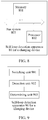
- Mobile power supplies are widely used because they can conveniently charge devices such as tablet computers and mobile phones. As shown in
FIG. 1 , amobile power supply 1 includes a large-capacity battery 10, a powersupply management circuit 11, aninbound charging interface 12, anoutbound charging interface 13, and the like. Theinbound charging interface 12 is used by an external battery charger to charge themobile power supply 1. Theoutbound charging interface 13 is used by themobile power supply 1 to charge an external device (such as a tablet computer or a mobile phone). The mobile power supply preferably can perform inbound charging and outbound charging at the same time, so that a user can conveniently use the mobile power supply. - As shown in
FIG. 1 , some users may directly connect theinbound charging interface 12 to theoutbound charging interface 13. As a result, a current loop (the current loop is referred to as a self-loop below) is formed in themobile power supply 1. Consequently, electric energy of themobile power supply 1 is consumed in vain. In addition, if theinbound charging interface 12 and theoutbound charging interface 13 are connected for an excessively long time, excessive heat of themobile power supply 1 may even damage an internal circuit of themobile power supply 1. Currently, it is not detected whether a self-loop exists in themobile power supply 1 when themobile power supply 1 performs inbound charging and outbound charging at the same time. - Embodiments of the present invention provide a self-loop detection method and apparatus for a charging device, so as to detect, when the charging device performs inbound charging and outbound charging at the same time, whether a self-loop exists in the charging device.
- To achieve the foregoing objective, the following technical solutions are used in the embodiments of the present invention:
- According to a first aspect, a self-loop detection method for a charging device is provided, where the charging device includes an inbound charging interface and an outbound charging interface, where the inbound charging interface includes a positive signal cable D; and a negative signal cable Di, the outbound charging interface includes a positive signal cable Do and a negative signal cable Do, the inbound charging interface is in an inbound charging state, and the outbound charging interface is in an outbound charging state; and the method includes:
- switching the positive signal cable Do and the negative signal cable Do from a connected state to a disconnected state; and
- detecting whether the positive signal cable D; and the negative signal cable Di are switched from a connected state to a disconnected state; and if yes, determining that a self-loop exists in the charging device.
- With reference to the first aspect, in a first possible implementation manner, after the determining that a self-loop exists in the charging device, the method further includes:
- controlling the outbound charging interface to enter an outbound charging stop state; or
- controlling the inbound charging interface to enter an inbound charging stop state; or
- controlling a value of a current flowing into the inbound charging interface, so that the current value is less than a maximum current value that exists when the self-loop exists in the charging device.
- With reference to the first aspect, in a second possible implementation manner, after the determining that a self-loop exists in the charging device, the method further includes:
- outputting a prompt message, where the prompt message is used to remind a user that the self-loop exists in the charging device.
- With reference to the second possible implementation manner of the first aspect, in a third possible implementation manner, after the outputting a prompt message, the method further includes:
- determining whether the self-loop of the charging device is eliminated; and
- if not, controlling the outbound charging interface to enter an outbound charging stop state; or
- if not, controlling the inbound charging interface to enter an inbound charging stop state; or
- if not, controlling a value of a current flowing into the inbound charging interface, so that the current value is less than a maximum current value that exists when the self-loop exists in the charging device.
- With reference to the third possible implementation manner of the first aspect, in a fourth possible implementation manner, the determining whether the self-loop of the charging device is eliminated includes:
- detecting whether a connection cable is removed from the outbound charging interface and/or detecting whether a connection cable is removed from the inbound charging interface; and
- if the connection cable is removed, determining that the self-loop of the charging device is eliminated.
- According to a second aspect, a self-loop detection method for a charging device is provided, where the charging device includes an inbound charging interface and an outbound charging interface; and the method includes:
- switching the outbound charging interface from an outbound charging state to an outbound charging stop state; and
- detecting whether the inbound charging interface is switched from an inbound charging state to an inbound charging stop state; and if yes, determining that a self-loop exists in the charging device when the outbound charging interface is in the outbound charging state.
- With reference to the second aspect, in a first possible implementation manner, after the determining that a self-loop exists in the charging device when the outbound charging interface is in the outbound charging state, the method further includes:
- outputting a prompt message, where the prompt message is used to remind a user that a self-loop exists in the charging device when the outbound charging interface is in the outbound charging state again.
- According to a third aspect, a self-loop detection apparatus for a charging device is provided, where the charging device includes an inbound charging interface and an outbound charging interface, where the inbound charging interface includes a positive signal cable Di and a negative signal cable Di, the outbound charging interface includes a positive signal cable Do and a negative signal cable Do, the inbound charging interface is in an inbound charging state, and the outbound charging interface is in an outbound charging state; and the apparatus includes:
- a switching unit, configured to switch the positive signal cable Do and the negative signal cable Do from a connected state to a disconnected state;
- a detection unit, configured to detect whether the positive signal cable Di and the negative signal cable Di are switched from a connected state to a disconnected state; and
- a determining unit, configured to: when the detection unit detects that the positive signal cable Di and the negative signal cable Di are switched from the connected state to the disconnected state, determine that a self-loop exists in the charging device.
- With reference to the third aspect, in a first possible implementation manner, the apparatus further includes:
- a control unit, configured to: control the outbound charging interface to enter an outbound charging stop state; or
- control the inbound charging interface to enter an inbound charging stop state; or
- control a value of a current flowing into the inbound charging interface, so that the current value is less than a maximum current value that exists when the self-loop exists in the charging device.
- With reference to the third aspect, in a second possible implementation manner, the apparatus further includes:
- an output unit, configured to output a prompt message, where the prompt message is used to remind a user that the self-loop exists in the charging device.
- With reference to the second possible implementation manner of the third aspect, in a third possible implementation manner, the determining unit is further configured to determine whether the self-loop of the charging device is eliminated; and
the control unit is further configured to: when the determining unit determines that the self-loop of the charging device is not eliminated, control the outbound charging interface to enter an outbound charging stop state; or control the inbound charging interface to enter an inbound charging stop state; or control a value of a current flowing into the inbound charging interface, so that the current value is less than a maximum current value that exists when the self-loop exists in the charging device. - With reference to the third possible implementation manner of the third aspect, in a fourth possible implementation manner, the detection unit is further configured to: detect whether a connection cable is removed from the outbound charging interface and/or detect whether a connection cable is removed from the inbound charging interface; and
the determining unit is further configured to: when the detection unit detects that the connection cable is removed from the outbound charging interface and/or detects that the connection cable is removed from the inbound charging interface, determine that the self-loop of the charging device is eliminated. - According to a fourth aspect, a self-loop detection apparatus for a charging device is provided, where the charging device includes an inbound charging interface and an outbound charging interface; and the apparatus includes:
- a switching unit, configured to switch the outbound charging interface from an outbound charging state to an outbound charging stop state;
- a detection unit, configured to detect whether the inbound charging interface is switched from an inbound charging state to an inbound charging stop state; and
- a determining unit, configured to: when the detection unit detects that the inbound charging interface is switched from the inbound charging state to the inbound charging stop state, determine that a self-loop exists in the charging device when the outbound charging interface is in the outbound charging state.
- With reference to the fourth aspect, in a first possible implementation manner, the apparatus further includes:
- an output unit, configured to output a prompt message, where the prompt message is used to remind a user that a self-loop exists in the charging device when the outbound charging interface is in the outbound charging state again.
- According to a fifth aspect, a self-loop detection apparatus for a charging device is provided, where the charging device includes an inbound charging interface and an outbound charging interface, where the inbound charging interface includes a positive signal cable Di and a negative signal cable Di, the outbound charging interface includes a positive signal cable Do and a negative signal cable Do, the inbound charging interface is in an inbound charging state, and the outbound charging interface is in an outbound charging state; and the apparatus includes: a memory and a processor, where
the memory is configured to store a set of code, and the code is used to control the processor to perform the following operations: - switching the positive signal cable Do and the negative signal cable Do from a connected state to a disconnected state;
- detecting whether the positive signal cable Di and the negative signal cable Di are switched from a connected state to a disconnected state; and
- determining, when it is detected that the positive signal cable Di and the negative signal cable Di are switched from the connected state to the disconnected state, that a self-loop exists in the charging device.
- With reference to the fifth aspect, in a first possible implementation manner, the processor is further configured to:
- control the outbound charging interface to enter an outbound charging stop state; or
- control the inbound charging interface to enter an inbound charging stop state; or
- control a value of a current flowing into the inbound charging interface, so that the current value is less than a maximum current value that exists when the self-loop exists in the charging device.
- With reference to the fifth aspect, in a second possible implementation manner, the processor is further configured to:
- output a prompt message, where the prompt message is used to remind a user that the self-loop exists in the charging device.
- With reference to the second possible implementation manner of the fifth aspect, in a third possible implementation manner, the processor is further configured to:
- determine whether the self-loop of the charging device is eliminated; and
- when it is determined that the self-loop of the charging device is not eliminated, control the outbound charging interface to enter an outbound charging stop state; or control the inbound charging interface to enter an inbound charging stop state; or control a value of a current flowing into the inbound charging interface, so that the current value is less than a maximum current value that exists when the self-loop exists in the charging device.
- With reference to the third possible implementation manner of the fifth aspect, in a fourth possible implementation manner, the processor is further configured to:
- detect whether a connection cable is removed from the outbound charging interface and/or detect whether a connection cable is removed from the inbound charging interface; and
- when it is detected that the connection cable is removed from the outbound charging interface and/or it is detected that the connection cable is removed from the inbound charging interface, determine that the self-loop of the charging device is eliminated.
- According to a sixth aspect, a self-loop detection apparatus for a charging device is provided, where the charging device includes an inbound charging interface and an outbound charging interface; and the apparatus includes: a memory and a processor, where
the memory is configured to store a set of code, and the code is used to control the processor to perform the following operations: - switching the outbound charging interface from an outbound charging state to an outbound charging stop state;
- detecting whether the inbound charging interface is switched from an inbound charging state to an inbound charging stop state; and
- determining, when it is detected that the inbound charging interface is switched from the inbound charging state to the inbound charging stop state, that a self-loop exists in the charging device when the outbound charging interface is in the outbound charging state.
- With reference to the sixth aspect, in a first possible implementation manner, the processor is further configured to: output a prompt message, where the prompt message is used to remind a user that a self-loop exists in the charging device when the outbound charging interface is in the outbound charging state again.
- According to the self-loop detection method and apparatus for a charging device provided in the embodiments of the present invention, when an outbound charging interface is in an outbound charging state, an inbound charging interface is in an inbound charging state, and a positive signal cable Di is connected to a negative signal cable Di, whether a self-loop exists in the charging device is detected. When the self-loop exists in the charging device, and a positive signal cable Do of the outbound charging interface and a negative signal cable Do of the outbound charging interface are switched from a connected state to a disconnected state, the positive signal cable Di of the inbound charging interface and the negative signal cable Di of the inbound charging interface are also switched from a connected state to a disconnected state. Therefore, it may be detected, according to this feature, that the self-loop exists in the charging device.
- To describe the technical solutions in the embodiments of the present invention or in the prior art more clearly, the following briefly describes the accompanying drawings required for describing the embodiments or the prior art. Apparently, the accompanying drawings in the following description show merely some embodiments of the present invention, and persons of ordinary skill in the art may still derive other drawings from these accompanying drawings without creative efforts.
-
FIG. 1 is a schematic composition diagram of a mobile power supply in the prior art; -
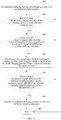
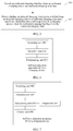
FIG. 2 is a flowchart of a self-loop detection method for a charging device according to an embodiment of the present invention; -
FIG. 3 is a schematic composition diagram of a charging device according to an embodiment of the present invention; -
FIG. 4 is a flowchart of another self-loop detection method for a charging device according to an embodiment of the present invention; -
FIG. 5 is a flowchart of still another self-loop detection method for a charging device according to an embodiment of the present invention; -
FIG. 6 is a schematic composition diagram of a self-loop detection apparatus for a charging device according to an embodiment of the present invention; -
FIG. 7 is a schematic composition diagram of another self-loop detection apparatus for a charging device according to an embodiment of the present invention; -
FIG. 8 is a schematic composition diagram of another self-loop detection apparatus for a charging device according to an embodiment of the present invention; -
FIG. 9 is a schematic composition diagram of another self-loop detection apparatus for a charging device according to an embodiment of the present invention; -
FIG. 10 is a schematic composition diagram of another self-loop detection apparatus for a charging device according to an embodiment of the present invention; and -
FIG. 11 is a schematic composition diagram of another self-loop detection apparatus for a charging device according to an embodiment of the present invention. - The following clearly and completely describes the technical solutions in the embodiments of the present invention with reference to the accompanying drawings in the embodiments of the present invention. Apparently, the described embodiments are merely some but not all of the embodiments of the present invention. All other embodiments obtained by persons of ordinary skill in the art based on the embodiments of the present invention without creative efforts shall fall within the protection scope of the present invention.
- This embodiment of the present invention provides a self-loop detection method for a charging device. The charging device includes an inbound charging interface and an outbound charging interface. The inbound charging interface includes a positive signal cable Di and a negative signal cable Di. The outbound charging interface includes a positive signal cable Do and a negative signal cable Do. The inbound charging interface is in an inbound charging state, and the outbound charging interface is in an outbound charging state. As shown in
FIG. 2 , the method includes the following steps. - 201: Switch the positive signal cable Do and the negative signal cable Do from a connected state to a disconnected state.
- It should be noted that the charging device in this embodiment of the present invention may charge an external device (such as a mobile phone or a tablet computer), and an external battery charger may also charge the charging device. Specifically, the charging device may be a mobile power supply, or may be another device having the foregoing function. This embodiment of the present invention may be executed by the charging device, or may be a detection device that may implement the foregoing method. This is not limited in this embodiment of the present invention. An example of the technical solution provided in this embodiment of the present invention is described, and this embodiment of the present invention is executed, for example, by a detection device.
- As shown in
FIG. 3 , acharging device 3 includes an inbound charging interface 31 and anoutbound charging interface 32. The inbound charging interface 31 and theoutbound charging interface 32 both include a positive signal cable D (may also be represented as "D+") and a negative signal cable D (may also be represented as "D-"). In this embodiment of the present invention, for ease of description and distinguishing, the positive signal cable D of the inbound charging interface 31 is represented as a positive signal cable Di (represented as Di+ inFIG. 3 ), and the negative signal cable D of the inbound charging interface 31 is represented as a negative signal cable Di (represented as Di- inFIG. 3 ). The positive signal cable D of theoutbound charging interface 32 is represented as a positive signal cable Do (represented as Do+ inFIG. 3 ), and the negative signal cable D of theoutbound charging interface 32 is represented as a negative signal cable Do (represented as Do- inFIG. 3 ). - When the inbound charging interface 31 is directly connected to the
outbound charging interface 32, and the inbound charging interface 31 and theoutbound charging interface 32 are both in working states, a self-loop exists in thecharging device 3. - In addition, referring to
FIG. 3 , the inbound charging interface 31 and theoutbound charging interface 32 both include a power cable (both are represented as V inFIG. 3 ) and a ground cable (both are represented as G inFIG. 3 ). Generally, the inbound charging interface 31 and theoutbound charging interface 32 are connected to a same ground cable. The chargingdevice 3 may further include a large-capacity battery, a power supply management circuit, and the like (not shown inFIG. 3 ). - During specific implementation of
step 201, a switch may be disposed between the positive signal cable Do and the negative signal cable Do. The detection device may control, by using the switch, the positive signal cable Do and the negative signal cable Do to connect to or disconnect from each other. - It should be noted that in this embodiment of the present invention, after the positive signal cable Do and the negative signal cable Do are switched from the connected state to the disconnected state, the outbound charging interface of the charging device is still in the outbound charging state, that is, the power cable of the outbound charging interface is in a power supplying state.
- 202: Detect whether the positive signal cable Di and the negative signal cable Di are switched from a connected state to a disconnected state; and if yes, determine that a self-loop exists in the charging device.
- It should be noted that when an external battery charger charges the charging device, two ends of a connection cable connecting the external battery charger to the inbound charging interface of the charging device include power cables, ground cables, positive signal cable Ds, and negative signal cable Ds corresponding to the external battery charger and the inbound charging interface. The positive signal cable D and the negative signal cable D of the external battery charger are respectively marked as Dn+ and Dn-. When the external battery charger is a standard battery charger and the external battery charger charges the charging device, Dn+ is connected to Dn-, and Di+ is also connected to Di-, so as to form a loop that passes through Dn+, Dn-, Di-, and Di+, and finally goes back to Dn+. When the external battery charger is a non-standard battery charger and the external battery charger charges the charging device, Dn+ is not connected to Dn-, and Di+ is not connected to Di- either. Therefore, the charging device may determine, by detecting whether Di- is connected to Di+, whether the external battery charger is a standard battery charger.
- Similarly, when the charging device charges an external device, the external device may also detect, by using the foregoing method, whether the charging device is a standard battery charger.
- It should be noted that when an external battery charger charges the charging device, the charging device does not limit a magnitude of a current flowing into the charging device if identifying that the external battery charger is a standard battery charger; and the charging device limits a magnitude of a current flowing into the charging device if identifying that the external battery charger is a non-standard battery charger. In a charging process, the charging device identifies, only when charging just starts, whether an external battery charger is a standard battery charger. This same principle applies when the charging device charges an external device.
- In this embodiment of the present invention, provided that the charging device is in the outbound charging state, the positive signal cable Do is connected to the negative signal cable Do. Therefore, if a self-loop exists in the charging device, the positive signal cable Di is connected to the negative signal cable Di. When the positive signal cable Do and the negative signal cable Do are switched from the connected state to the disconnected state, the positive signal cable Di and the negative signal cable Di are also switched from the connected state to the disconnected state. Therefore, whether the self-loop exists in the charging device may be detected according to this feature.
- The following uses a table (Table 1) to more clearly describe correspondences among a state between the positive signal cable Di and the negative signal cable Di (the state is connected or disconnected), whether a self-loop exists in a power supply device, and whether the positive signal cable Di and the negative signal cable Di are switched from the connected state to the disconnected state (referred to as "whether a switchover is performed" in the table), before or after the detection device performs
step 201 when the inbound charging interface is in different states. In the table, a state between the positive signal cable Di and the negative signal cable Di beforestep 201 is referred to as an A state, and a state between the positive signal cable Di and the negative signal cable Di afterstep 201 is referred to as a B state.Table 1 Working state of an inbound charging interface Whether a self-loop exists in a power supply device A state B state Whether a switchover is performed Inbound working stop state No Disconnected Disconnected No Inbound working state (connected to a standard battery charger) No Connected Connected No Inbound working state (connected to a non-standard battery charger) No Disconnected Disconnected No Inbound working state (connected to an outbound charging interface) Yes Connected Disconnected Yes - It may be seen from Table 1 that, provided that the outbound charging interface is in the outbound charging state, the detection device may determine, by detecting whether the positive signal cable Di and the negative signal cable Di are switched between the connected state and the disconnected state, whether a self-loop exists in the charging device.
- It may also be known from Table 1 that, only when the outbound charging interface is in the outbound charging state, the inbound charging interface is in the inbound charging state, and the positive signal cable Di is connected to the negative signal cable Di, a self-loop may exist in the charging device. In this embodiment of the present invention, detection is performed on the charging device after it is determined that the positive signal cable Di is connected to the negative signal cable Di, thereby improving detection efficiency of the detection device.
- It should be noted that when the detection device has not detected that a self-loop exists in the charging device, the positive signal cable Do and the negative signal cable Do of the charging device may be restored to a short-circuit state.
- Optionally, after
step 202, the method may further include: - controlling the outbound charging interface to enter an outbound charging stop state; or
- controlling the inbound charging interface to enter an inbound charging stop state; or
- controlling a value of a current flowing into the inbound charging interface, so that the current value is less than a maximum current value that exists when the self-loop exists in the charging device.
- It should be noted that when the detection device controls the outbound charging interface to enter the outbound charging stop state or controls the inbound charging interface to enter the inbound charging stop state, the self-loop existing in the charging device is eliminated.
- When the detection device controls the value of the current flowing into the inbound charging interface, the self-loop still exists in the charging device. However, because the current value is less than the maximum current value that exists when the self-loop exists in the charging device, electric energy consumption caused because the self-loop exists in the charging device may be reduced. In addition, a smaller current value is better. This is because a smaller current value indicates smaller electric energy consumption caused because the self-loop exists in the charging device. It should be noted that because the charging device identifies at the beginning that an external battery charger (when a self-loop exists in the charging device, the charging device charges itself) that charges the charging device is a standard battery charger, a magnitude of a current flowing into the charging device is not limited. When a self-loop exists in the charging device, the detection device controls a value of a current flowing into the inbound charging interface.
- Specifically, when the detection device detects that a self-loop exists in the charging device, the detection device may output a control message to a power supply management circuit in the charging device. The power supply management circuit controls an internal circuit of the power supply management circuit according to the control message, so as to control a state of the inbound charging interface or the outbound charging interface.
- Optionally, after
step 202, the method may further include: outputting a prompt message. The prompt message is used to remind a user that the self-loop exists in the charging device. - For example, the detection device may remind a user by turning on or turning off an indicator or displaying a digit/word on a screen. When the detection device has a communications function, the detection device may also remind the user by sending a message to a device such as a mobile phone of the user. This is not limited in this embodiment of the present invention. In addition, when a user knows that the self-loop exists in the charging device, the user may manually eliminate the self-loop. Specifically, the self-loop of the charging device may be eliminated by removing a connection cable from the inbound charging interface and/or the outbound charging interface of the charging device.
- Optionally, after the outputting a prompt message, the method further includes:
- determining whether the self-loop of the charging device is eliminated; and
- if not, controlling the outbound charging interface to enter an outbound charging stop state; or
- if not, controlling the inbound charging interface to enter an inbound charging stop state; or
- if not, controlling a value of a current flowing into the inbound charging interface, so that the current value is less than a maximum current value that exists when the self-loop exists in the charging device.
- Optionally, the determining whether the self-loop of the charging device is eliminated includes: detecting whether a connection cable is removed from the outbound charging interface and/or detecting whether a connection cable is removed from the inbound charging interface; and if the connection cable is removed, determining that the self-loop of the charging device is eliminated.
- For example, the detection device may detect whether a voltage of the power cable of the inbound charging interface is zero, and if the voltage of the power cable of the inbound charging interface is zero, the detection device determines that the connection cable is removed from the inbound charging interface.
- It should be noted that when a user removes the connection cable from the outbound charging interface or the inbound charging interface of the charging device, the detection device may detect this case. If the detection device detects this case within a particular time period after the detection device outputs the prompt message, it may be determined that the self-loop of the charging device is eliminated. If the detection device does not detect this case within a particular time period after the detection device outputs the prompt message, it may be determined that the self-loop of the charging device is not eliminated.
- It should be noted that in this embodiment of the present invention, when the outbound charging interface is in the outbound charging stop state, the connection cable is not removed from the outbound charging interface; and when the inbound charging interface is in the inbound charging stop state, the connection cable is not removed from the inbound charging interface either.
- In addition, a condition that triggers the outbound charging interface to be in the outbound charging state again may be that: a user manually performs setting, or the connection cable on the outbound charging interface is connected to the outbound charging interface again, or the connection cable on the inbound charging interface is connected to the inbound charging interface again.
- According to the self-loop detection method for a charging device provided in this embodiment of the present invention, when an outbound charging interface is in an outbound charging state, an inbound charging interface is in an inbound charging state, and a positive signal cable Di is connected to a negative signal cable Di, whether a self-loop exists in the charging device is detected. When the self-loop exists in the charging device, and a positive signal cable Do of the outbound charging interface and a negative signal cable Do of the outbound charging interface are switched from a connected state to a disconnected state, the positive signal cable Di of the inbound charging interface and the negative signal cable Di of the inbound charging interface are also switched from a connected state to a disconnected state. Therefore, it may be detected, according to this feature, that the self-loop exists in the charging device.
- This embodiment is a specific embodiment of the self-loop detection method for a charging device provided in the foregoing embodiment. For related explanations in this embodiment, refer to the foregoing embodiment. As shown in
FIG. 4 , the self-loop detection method for a charging device includes the following steps. - 401: An outbound charging interface of a charging device is in an outbound charging state.
- In this case, a positive signal cable Do of the outbound charging interface is connected to a negative signal cable Do of the outbound charging interface. Specifically, a switch may be disposed between the positive signal cable Do and the negative signal cable Do. A detection device may control, by using the switch, the positive signal cable Do and the negative signal cable Do to connect to or disconnect from each other.
- 402: Detect whether an inbound charging interface of the charging device is in an inbound charging state.
- If yes, perform
step 403; and if not, performstep 407. - Specifically, when the detection device detects that there is a voltage on a power cable of the inbound charging interface, it is considered that the inbound charging interface is in the inbound charging state.
- 403: Detect whether a positive signal cable Di of the inbound charging interface is connected to a negative signal cable Di of the inbound charging interface.
- If yes, perform
step 404; and if not, performstep 407. - It should be noted that because the positive signal cable Do of the outbound charging interface is connected to the negative signal cable Do of the outbound charging interface, when a self-loop exists in the charging device, the positive signal cable Di of the inbound charging interface is connected to the negative signal cable Di of the inbound charging interface.
- It should be noted that in this embodiment, a condition that triggers the detection device to detect whether a self-loop exists in the charging device is that: the outbound charging interface is in the outbound charging state, the inbound charging interface is in the inbound charging state, and the positive signal cable Di is connected to the negative signal cable Di.
- 404: Switch a positive signal cable Do of the outbound charging interface and a negative signal cable Do of the outbound charging interface from a connected state to a disconnected state.
- 405: Detect whether the positive signal cable Di of the inbound charging interface and the negative signal cable Di of the inbound charging interface are switched to a disconnected state.
- If yes, it is determined that a self-loop exists in the charging device, and perform
step 406. If not, performstep 407. - 406: Control the outbound charging interface to enter an outbound charging stop state.
- 407: End.
- According to the self-loop detection method for a charging device provided in this embodiment of the present invention, when an outbound charging interface is in an outbound charging state, an inbound charging interface is in an inbound charging state, and a positive signal cable Di is connected to a negative signal cable Di, whether a self-loop exists in the charging device is detected. When the self-loop exists in the charging device, and a positive signal cable Do of the outbound charging interface and a negative signal cable Do of the outbound charging interface are switched from a connected state to a disconnected state, the positive signal cable Di of the inbound charging interface and the negative signal cable Di of the inbound charging interface are also switched from a connected state to a disconnected state. Therefore, it may be detected, according to this feature, that the self-loop exists in the charging device.
- This embodiment of the present invention provides a self-loop detection method for a charging device. The charging device includes an inbound charging interface and an outbound charging interface. As shown in
FIG. 5 , the method includes the following steps. - 501: Switch the outbound charging interface from an outbound charging state to an outbound charging stop state.
- For related explanations in this embodiment of the present invention, refer to the foregoing embodiment.
- Specifically, when the outbound charging interface of the charging device starts to perform outbound charging and the inbound charging interface starts to perform inbound charging, a detection device may start to detect whether a self-loop exists in the charging device.
- 502: Detect whether the inbound charging interface is switched from an inbound charging state to an inbound charging stop state; and if yes, determine that a self-loop exists in the charging device when the outbound charging interface is in the outbound charging state.
- Specifically, when the self-loop exists in the charging device, the inbound charging interface and the outbound charging interface of the charging device are connected to each other. Therefore, when the outbound charging interface is switched from the outbound charging state to the outbound charging stop state, the inbound charging interface is naturally switched from the inbound charging state to the inbound charging stop state. Therefore, whether the self-loop exists in the charging device may be detected according to this feature.
- Specifically, after
step 501, the detection device has eliminated the self-loop from the charging device. However, a connection cable that connects the inbound charging interface and the outbound charging interface of the charging device is not removed. Therefore, the self-loop still exists when the charging device is started at a next time. - Optionally, after
step 502, the method may further include: outputting a prompt message. The prompt message is used to remind a user that a self-loop exists in the charging device when the outbound charging interface is in the outbound charging state again. - Specifically, when seeing the prompt message, a user may remove the connection cable that is connected to the inbound charging interface and/or the outbound charging interface of the charging device, so as to avoid that the self-loop still exists in the charging device when the charging device is started at a next time.
- In addition, a condition that triggers the outbound charging interface to be in the outbound charging state again may be that: a user manually performs setting, or the connection cable on the outbound charging interface is connected to the outbound charging interface again, or the connection cable on the inbound charging interface is connected to the inbound charging interface again.
- According to the self-loop detection method for a charging device provided in this embodiment of the present invention, when a self-loop exists in the charging device, an inbound charging interface and an outbound charging interface of the charging device are connected to each other. Therefore, when the outbound charging interface is switched from an outbound charging state to an outbound charging stop state, the inbound charging interface is naturally switched from an inbound charging state to an inbound charging stop state. Therefore, a detection device may determine, according to this feature, whether the self-loop exists in the charging device.
- This embodiment of the present invention provides a self-loop detection apparatus 60 for a charging device, to execute the self-loop detection method for a charging device shown in
FIG. 2 . As shown inFIG. 6 , the apparatus 60 includes: a switchingunit 601, adetection unit 602, and a determiningunit 603. - The
switching unit 601 is configured to switch the positive signal cable Do and the negative signal cable Do from a connected state to a disconnected state. - The
detection unit 602 is configured to detect whether the positive signal cable Di and the negative signal cable Di are switched from a connected state to a disconnected state. - The determining
unit 603 is configured to: when thedetection unit 602 detects that the positive signal cable Di and the negative signal cable Di are switched from the connected state to the disconnected state, determine that a self-loop exists in the charging device. - Optionally, as shown in
FIG. 7 , the apparatus 60 further includes: - a
control unit 604, configured to: control the outbound charging interface to enter an outbound charging stop state; or control the inbound charging interface to enter an inbound charging stop state; or control a value of a current flowing into the inbound charging interface, so that the current value is less than a maximum current value that exists when the self-loop exists in the charging device. - Optionally, as shown in
FIG. 7 , the apparatus 60 further includes anoutput unit 605, configured to output a prompt message. The prompt message is used to remind a user that the self-loop exists in the charging device. - Optionally, the determining
unit 603 is further configured to determine whether the self-loop of the charging device is eliminated; and thecontrol unit 604 is further configured to: when the determiningunit 603 determines that the self-loop of the charging device is not eliminated, control the outbound charging interface to enter an outbound charging stop state; or control the inbound charging interface to enter an inbound charging stop state; or control a value of a current flowing into the inbound charging interface, so that the current value is less than a maximum current value that exists when the self-loop exists in the charging device. - Optionally, the
detection unit 602 is further configured to: detect whether a connection cable is removed from the outbound charging interface and/or detect whether a connection cable is removed from the inbound charging interface; and the determiningunit 603 is further configured to: when thedetection unit 602 detects that the connection cable is removed from the outbound charging interface and/or detects that the connection cable is removed from the inbound charging interface, determine that the self-loop of the charging device is eliminated. - According to the self-loop detection apparatus for a charging device provided in this embodiment of the present invention, when an outbound charging interface of the charging device is in an outbound charging state, an inbound charging interface of the charging device is in an inbound charging state, and a positive signal cable Di is connected to a negative signal cable Di, whether a self-loop exists in the charging device is detected. When the self-loop exists in the charging device, and a positive signal cable Do of the outbound charging interface and a negative signal cable Do of the outbound charging interface are switched from a connected state to a disconnected state, the positive signal cable Di of the inbound charging interface and the negative signal cable Di of the inbound charging interface are also switched from a connected state to a disconnected state. Therefore, it may be detected, according to this feature, that the self-loop exists in the charging device.
- During hardware implementation, the units in Embodiment 4 may be built in or independent of a processor of the self-loop detection apparatus for a charging device in a form of hardware, or may be stored in a memory of the self-loop detection apparatus for a charging device in a form of software, so as to be invoked by the processor to perform operations corresponding to the foregoing units. The processor may be a central processing unit (CPU for short), a microprocessor, a single-chip microcomputer, and the like.
- As shown in
FIG. 8, FIG. 8 shows a self-loop detection apparatus 80 for a charging device according to an embodiment of the present invention, to execute the self-loop detection method for a charging device shown inFIG. 2 . The apparatus 80 includes: amemory 801, aprocessor 802, and abus system 803. - The
memory 801 and theprocessor 802 are coupled together by using thebus system 803. In addition to a data bus, thebus system 803 may further include a power supply bus, a control bus, a state signal bus, and the like. However, for a purpose of clear description, various types of buses are all marked as thebus system 803 in the figure. - The
memory 801 is configured to store a set of code, and the code is used to control theprocessor 802 to perform the following operations: - switching the positive signal cable Do and the negative signal cable Do from a connected state to a disconnected state;
- detecting whether the positive signal cable Di and the negative signal cable Di are switched from a connected state to a disconnected state; and
- determining, when it is detected that the positive signal cable Di and the negative signal cable Di are switched from the connected state to the disconnected state, that a self-loop exists in the charging device.
- Optionally, the
processor 802 is further configured to: - control the outbound charging interface to enter an outbound charging stop state; or control the inbound charging interface to enter an inbound charging stop state; or control a value of a current flowing into the inbound charging interface, so that the current value is less than a maximum current value that exists when the self-loop exists in the charging device.
- Optionally, the
processor 802 is further configured to: output a prompt message. The prompt message is used to remind a user that the self-loop exists in the charging device. - Optionally, the
processor 802 is further configured to: determine whether the self-loop of the charging device is eliminated; and when it is determined that the self-loop of the charging device is not eliminated, control the outbound charging interface to enter an outbound charging stop state; or control the inbound charging interface to enter an inbound charging stop state; or control a value of a current flowing into the inbound charging interface, so that the current value is less than a maximum current value that exists when the self-loop exists in the charging device. - Optionally, the
processor 802 is further configured to: detect whether a connection cable is removed from the outbound charging interface and/or detect whether a connection cable is removed from the inbound charging interface; and
when it is detected that the connection cable is removed from the outbound charging interface and/or it is detected that the connection cable is removed from the inbound charging interface, determine that the self-loop of the charging device is eliminated. - According to the self-loop detection apparatus for a charging device provided in this embodiment of the present invention, when an outbound charging interface of the charging device is in an outbound charging state, an inbound charging interface of the charging device is in an inbound charging state, and a positive signal cable Di is connected to a negative signal cable Di, whether a self-loop exists in the charging device is detected. When the self-loop exists in the charging device, and a positive signal cable Do of the outbound charging interface and a negative signal cable Do of the outbound charging interface are switched from a connected state to a disconnected state, the positive signal cable Di of the inbound charging interface and the negative signal cable Di of the inbound charging interface are also switched from a connected state to a disconnected state. Therefore, it may be detected, according to this feature, that the self-loop exists in the charging device.
- This embodiment of the present invention provides a self-loop detection apparatus 90 for a charging device, to execute the self-loop detection method for a charging device shown in
FIG. 5 . As shown inFIG. 9 , the apparatus 90 includes: a switchingunit 901, adetection unit 902, and a determiningunit 903. - The
switching unit 901 is configured to switch the outbound charging interface from an outbound charging state to an outbound charging stop state. - The
detection unit 902 is configured to detect whether the inbound charging interface is switched from an inbound charging state to an inbound charging stop state. - The determining
unit 903 is configured to: when thedetection unit 902 detects that the inbound charging interface is switched from the inbound charging state to the inbound charging stop state, determine that a self-loop exists in the charging device when the outbound charging interface is in the outbound charging state. - Optionally, as shown in
FIG. 10 , the apparatus 90 further includes: - an
output unit 904, configured to output a prompt message, where the prompt message is used to remind a user that a self-loop exists in the charging device when the outbound charging interface is in the outbound charging state again. - According to the self-loop detection apparatus for a charging device provided in this embodiment of the present invention, when a self-loop exists in the charging device, an inbound charging interface and an outbound charging interface of the charging device are connected to each other. Therefore, when the outbound charging interface is switched from an outbound charging state to an outbound charging stop state, the inbound charging interface is naturally switched from an inbound charging state to an inbound charging stop state. Therefore, the detection apparatus may determine, according to this feature, whether the self-loop exists in the charging device.
- During hardware implementation, the units in Embodiment 6 may be built in or independent of a processor of the self-loop detection apparatus for a charging device in a form of hardware, or may be stored in a memory of the self-loop detection apparatus for a charging device in a form of software, so as to be invoked by the processor to perform operations corresponding to the foregoing units. The processor may be a central processing unit (CPU for short), a microprocessor, a single-chip microcomputer, and the like.
- As shown in
FIG. 11, FIG. 11 shows a self-loop detection apparatus 110 for a charging device according to an embodiment of the present invention, to execute the self-loop detection method for a charging device shown inFIG. 5 . The apparatus 110 includes: amemory 1101, aprocessor 1102, and abus system 1103. - The
memory 1101 and theprocessor 1102 are coupled together by using thebus system 1103. In addition to a data bus, thebus system 1103 may further include a power bus, a control bus, a status signal bus, and the like. However, for a purpose of clear description, various types of buses are all marked as thebus system 1103 in the figure. - The
memory 1101 is configured to store a set of code, and the code is used to control theprocessor 1102 to perform the following operations: - switching the outbound charging interface from an outbound charging state to an outbound charging stop state;
- detecting whether the inbound charging interface is switched from an inbound charging state to an inbound charging stop state; and
- determining, when it is detected that the inbound charging interface is switched from the inbound charging state to the inbound charging stop state, that a self-loop exists in the charging device when the outbound charging interface is in the outbound charging state.
- Optionally, the
processor 1102 is further configured to output a prompt message. The prompt message is used to remind a user that a self-loop exists in the charging device when the outbound charging interface is in the outbound charging state again. - According to the self-loop detection apparatus for a charging device provided in this embodiment of the present invention, when a self-loop exists in the charging device, an inbound charging interface and an outbound charging interface of the charging device are connected to each other. Therefore, when the outbound charging interface is switched from an outbound charging state to an outbound charging stop state, the inbound charging interface is naturally switched from an inbound charging state to an inbound charging stop state. Therefore, the detection apparatus may determine, according to this feature, whether the self-loop exists in the charging device.
- In the several embodiments provided in the present application, it should be understood that the disclosed apparatus and method may be implemented in other manners. For example, the described apparatus embodiment is merely an example. For example, the unit division is merely logical function division and may be other division in actual implementation. For example, a plurality of units or components may be combined or integrated into another system, or some features may be ignored or not performed.
- In addition, functional units in the embodiments of the present invention may be integrated into one processing unit, or each of the units may exist alone physically, or two or more units are integrated into one unit. The integrated unit may be implemented in a form of hardware, or may be implemented in a form of hardware in addition to a software functional unit.
- When the foregoing integrated unit is implemented in a form of a software functional unit, the integrated unit may be stored in a computer-readable storage medium. The software functional unit is stored in a storage medium and includes several instructions for instructing a computer device (which may be a personal computer, a server, or a network device) to perform some of the steps of the methods described in the embodiments of the present invention. The foregoing storage medium includes: any medium that can store program code, such as a USB flash drive, a removable hard disk, a read-only memory (English: Read-Only Memory, ROM for short), a random access memory (English: Random Access Memory, RAM for short), a magnetic disk, or an optical disc.
Finally, it should be noted that the foregoing embodiments are merely intended for describing the technical solutions of the present invention, but not for limiting the present invention. Although the present invention is described in detail with reference to the foregoing embodiments, persons of ordinary skill in the art should understand that they may still make modifications to the technical solutions described in the foregoing embodiments or make equivalent replacements to some technical features thereof, without departing from the spirit and scope of the technical solutions of the embodiments of the present invention.
Claims (21)
- A self-loop detection method for a charging device, wherein the charging device comprises an inbound charging interface and an outbound charging interface, wherein the inbound charging interface comprises a positive signal cable Di and a negative signal cable Di, the outbound charging interface comprises a positive signal cable Do and a negative signal cable Do, the inbound charging interface is in an inbound charging state, and the outbound charging interface is in an outbound charging state; and the method comprises:switching the positive signal cable Do and the negative signal cable Do from a connected state to a disconnected state; anddetecting whether the positive signal cable Di and the negative signal cable Di are switched from a connected state to a disconnected state; and if yes, determining that a self-loop exists in the charging device.
- The method according to claim 1, wherein after the determining that a self-loop exists in the charging device, the method further comprises:controlling the outbound charging interface to enter an outbound charging stop state; orcontrolling the inbound charging interface to enter an inbound charging stop state; orcontrolling a value of a current flowing into the inbound charging interface, so that the current value is less than a maximum current value that exists when the self-loop exists in the charging device.
- The method according to claim 1, wherein after the determining that a self-loop exists in the charging device, the method further comprises:outputting a prompt message, wherein the prompt message is used to remind a user that the self-loop exists in the charging device.
- The method according to claim 3, wherein after the outputting a prompt message, the method further comprises:determining whether the self-loop of the charging device is eliminated; andif not, controlling the outbound charging interface to enter an outbound charging stop state; orif not, controlling the inbound charging interface to enter an inbound charging stop state; orif not, controlling a value of a current flowing into the inbound charging interface, so that the current value is less than a maximum current value that exists when the self-loop exists in the charging device.
- The method according to claim 4, wherein the determining whether the self-loop of the charging device is eliminated comprises:detecting whether a connection cable is removed from the outbound charging interface and/or detecting whether a connection cable is removed from the inbound charging interface; andif the connection cable is removed, determining that the self-loop of the charging device is eliminated.
- A self-loop detection method for a charging device, wherein the charging device comprises an inbound charging interface and an outbound charging interface; and the method comprises:switching the outbound charging interface from an outbound charging state to an outbound charging stop state; anddetecting whether the inbound charging interface is switched from an inbound charging state to an inbound charging stop state; and if yes, determining that a self-loop exists in the charging device when the outbound charging interface is in the outbound charging state.
- The method according to claim 6, wherein after the determining that a self-loop exists in the charging device when the outbound charging interface is in the outbound charging state, the method further comprises:outputting a prompt message, wherein the prompt message is used to remind a user that a self-loop exists in the charging device when the outbound charging interface is in the outbound charging state again.
- A self-loop detection apparatus for a charging device, wherein the charging device comprises an inbound charging interface and an outbound charging interface, wherein the inbound charging interface comprises a positive signal cable Di and a negative signal cable Di, the outbound charging interface comprises a positive signal cable Do and a negative signal cable Do, the inbound charging interface is in an inbound charging state, and the outbound charging interface is in an outbound charging state; and the apparatus comprises:a switching unit, configured to switch the positive signal cable Do and the negative signal cable Do from a connected state to a disconnected state;a detection unit, configured to detect whether the positive signal cable Di and the negative signal cable Di are switched from a connected state to a disconnected state; anda determining unit, configured to: when the detection unit detects that the positive signal cable Di and the negative signal cable Di are switched from the connected state to the disconnected state, determine that a self-loop exists in the charging device.
- The apparatus according to claim 8, wherein the apparatus further comprises:a control unit, configured to: control the outbound charging interface to enter an outbound charging stop state; orcontrol the inbound charging interface to enter an inbound charging stop state; orcontrol a value of a current flowing into the inbound charging interface, so that the current value is less than a maximum current value that exists when the self-loop exists in the charging device.
- The apparatus according to claim 8, wherein the apparatus further comprises:an output unit, configured to output a prompt message, wherein the prompt message is used to remind a user that the self-loop exists in the charging device.
- The apparatus according to claim 10, wherein
the determining unit is further configured to determine whether the self-loop of the charging device is eliminated; and
the control unit is further configured to: when the determining unit determines that the self-loop of the charging device is not eliminated, control the outbound charging interface to enter an outbound charging stop state; or control the inbound charging interface to enter an inbound charging stop state; or control a value of a current flowing into the inbound charging interface, so that the current value is less than a maximum current value that exists when the self-loop exists in the charging device. - The apparatus according to claim 11, wherein
the detection unit is further configured to: detect whether a connection cable is removed from the outbound charging interface and/or detect whether a connection cable is removed from the inbound charging interface; and
the determining unit is further configured to: when the detection unit detects that the connection cable is removed from the outbound charging interface and/or detects that the connection cable is removed from the inbound charging interface, determine that the self-loop of the charging device is eliminated. - A self-loop detection apparatus for a charging device, wherein the charging device comprises an inbound charging interface and an outbound charging interface; and the apparatus comprises:a switching unit, configured to switch the outbound charging interface from an outbound charging state to an outbound charging stop state;a detection unit, configured to detect whether the inbound charging interface is switched from an inbound charging state to an inbound charging stop state; anda determining unit, configured to: when the detection unit detects that the inbound charging interface is switched from the inbound charging state to the inbound charging stop state, determine that a self-loop exists in the charging device when the outbound charging interface is in the outbound charging state.
- The apparatus according to claim 13, wherein the apparatus further comprises:an output unit, configured to output a prompt message, wherein the prompt message is used to remind a user that a self-loop exists in the charging device when the outbound charging interface is in the outbound charging state again.
- A self-loop detection apparatus for a charging device, wherein the charging device comprises an inbound charging interface and an outbound charging interface, wherein the inbound charging interface comprises a positive signal cable Di and a negative signal cable Di, the outbound charging interface comprises a positive signal cable Do and a negative signal cable Do, the inbound charging interface is in an inbound charging state, and the outbound charging interface is in an outbound charging state; and the apparatus comprises: a memory and a processor, wherein
the memory is configured to store a set of code, and the code is used to control the processor to perform the following operations:switching the positive signal cable Do and the negative signal cable Do from a connected state to a disconnected state;detecting whether the positive signal cable Di and the negative signal cable Di are switched from a connected state to a disconnected state; anddetermining, when it is detected that the positive signal cable Di and the negative signal cable Di are switched from the connected state to the disconnected state, that a self-loop exists in the charging device. - The apparatus according to claim 15, wherein the processor is further configured to:control the outbound charging interface to enter an outbound charging stop state; orcontrol the inbound charging interface to enter an inbound charging stop state; orcontrol a value of a current flowing into the inbound charging interface, so that the current value is less than a maximum current value that exists when the self-loop exists in the charging device.
- The apparatus according to claim 15, wherein the processor is further configured to:output a prompt message, wherein the prompt message is used to remind a user that the self-loop exists in the charging device.
- The apparatus according to claim 17, wherein the processor is further configured to:determine whether the self-loop of the charging device is eliminated; andwhen it is determined that the self-loop of the charging device is not eliminated, control the outbound charging interface to enter an outbound charging stop state; or control the inbound charging interface to enter an inbound charging stop state; or control a value of a current flowing into the inbound charging interface, so that the current value is less than a maximum current value that exists when the self-loop exists in the charging device.
- The apparatus according to claim 18, wherein the processor is further configured to:detect whether a connection cable is removed from the outbound charging interface and/or detect whether a connection cable is removed from the inbound charging interface; andwhen it is detected that the connection cable is removed from the outbound charging interface and/or it is detected that the connection cable is removed from the inbound charging interface, determine that the self-loop of the charging device is eliminated.
- A self-loop detection apparatus for a charging device, wherein the charging device comprises an inbound charging interface and an outbound charging interface; and the apparatus comprises: a memory and a processor, wherein
the memory is configured to store a set of code, and the code is used to control the processor to perform the following operations:switching the outbound charging interface from an outbound charging state to an outbound charging stop state;detecting whether the inbound charging interface is switched from an inbound charging state to an inbound charging stop state; anddetermining, when it is detected that the inbound charging interface is switched from the inbound charging state to the inbound charging stop state, that a self-loop exists in the charging device when the outbound charging interface is in the outbound charging state. - The apparatus according to claim 20, wherein the processor is further configured to:output a prompt message, wherein the prompt message is used to remind a user that a self-loop exists in the charging device when the outbound charging interface is in the outbound charging state again.
Applications Claiming Priority (1)
| Application Number | Priority Date | Filing Date | Title |
|---|---|---|---|
| PCT/CN2015/073953 WO2016141554A1 (en) | 2015-03-10 | 2015-03-10 | Self-loop detection method and apparatus for charging device |
Publications (3)
| Publication Number | Publication Date |
|---|---|
| EP3258567A4 EP3258567A4 (en) | 2017-12-20 |
| EP3258567A1 true EP3258567A1 (en) | 2017-12-20 |
| EP3258567B1 EP3258567B1 (en) | 2018-09-19 |
Family
ID=56878764
Family Applications (1)
| Application Number | Title | Priority Date | Filing Date |
|---|---|---|---|
| EP15884237.7A Active EP3258567B1 (en) | 2015-03-10 | 2015-03-10 | Self-loop detection method and apparatus for charging device |
Country Status (5)
| Country | Link |
|---|---|
| US (1) | US10742057B2 (en) |
| EP (1) | EP3258567B1 (en) |
| JP (1) | JP6537085B2 (en) |
| CN (1) | CN106233568B (en) |
| WO (1) | WO2016141554A1 (en) |
Families Citing this family (3)
| Publication number | Priority date | Publication date | Assignee | Title |
|---|---|---|---|---|
| CN106532431A (en) * | 2016-12-28 | 2017-03-22 | 尚华 | Laser generation light introduction equipment applied to human body |
| JP6882934B2 (en) * | 2017-05-12 | 2021-06-02 | Dynabook株式会社 | Electronics and methods |
| CN113162163B (en) * | 2021-04-07 | 2025-03-28 | 深圳维普创新科技有限公司 | A method, device and circuit for detecting that a powered device is connected to a power supply device |
Family Cites Families (26)
| Publication number | Priority date | Publication date | Assignee | Title |
|---|---|---|---|---|
| GB2362769A (en) | 2000-05-26 | 2001-11-28 | Nokia Mobile Phones Ltd | Battery charging circuit in which power is supplied via a communications port |
| US6507172B2 (en) * | 2001-03-19 | 2003-01-14 | Maxim Integrated Products, Inc. | Universal serial bus powered battery charger |
| JP2005141732A (en) | 2003-10-15 | 2005-06-02 | Teac Corp | Electronic device having interface terminal and power supply cable connected thereto |
| TWM327596U (en) * | 2007-02-14 | 2008-02-21 | sheng-zhong Chen | Battery device and protection circuit/electronic device thereof |
| US20080238856A1 (en) * | 2007-03-29 | 2008-10-02 | Achintva Bhowmik | Using spatial distribution of pixel values when determining adjustments to be made to image luminance and backlight |
| TWI351802B (en) * | 2007-10-19 | 2011-11-01 | Richtek Technology Corp | Universal serial bus charger circuit and charging |
| KR20110081250A (en) * | 2008-10-02 | 2011-07-13 | 레이덴 에너지 인코오포레이티드 | Electronic current interrupter for battery |
| US20100277118A1 (en) * | 2009-05-04 | 2010-11-04 | Yen-Hui Wang | Automated power supply |
| KR101036037B1 (en) * | 2009-08-26 | 2011-05-19 | 에스비리모티브 주식회사 | Secondary battery |
| KR101667707B1 (en) * | 2009-10-22 | 2016-10-19 | 엘지전자 주식회사 | Mobile terminal and usb dedicated charger determinating method thereof |
| JP5487932B2 (en) * | 2009-12-14 | 2014-05-14 | トヨタ自動車株式会社 | Vehicle, power supply device and charging system |
| US8368355B2 (en) * | 2010-04-14 | 2013-02-05 | Apple Inc. | Portable electronic device power manager with current limit feedback control loop modification for stabilizing an external power supply |
| US20130193911A1 (en) | 2011-08-10 | 2013-08-01 | Garold C. Miller | Motion-actuated portable charger |
| JP4977797B1 (en) | 2011-11-30 | 2012-07-18 | 和征 榊原 | Battery system |
| JP2013142908A (en) * | 2012-01-06 | 2013-07-22 | Canon Inc | Electronic apparatus |
| FR2990078B1 (en) * | 2012-04-27 | 2014-05-09 | Renault Sa | METHOD FOR CONTROLLING CHARGE OF A BATTERY |
| US20130324167A1 (en) * | 2012-05-31 | 2013-12-05 | John A. Bevil | Wireless, multi-room ring and text notification system for cellular devices |
| JP2013250837A (en) * | 2012-06-01 | 2013-12-12 | Fuji Electric Co Ltd | False self loop configuration automatic detection device and method |
| CN103515662B (en) * | 2012-06-19 | 2016-03-02 | 上海斐讯数据通信技术有限公司 | Charging method and can the mobile device of supplying power for outside between a kind of mobile device |
| CN102761161B (en) * | 2012-06-19 | 2014-07-02 | 无锡中星微电子有限公司 | Mobile power supply |
| JP5590073B2 (en) * | 2012-06-21 | 2014-09-17 | トヨタ自動車株式会社 | Vehicle power control device |
| WO2014089068A1 (en) * | 2012-12-04 | 2014-06-12 | Halo2Cloud Llc | Portable power charger with rechargeable flashlight |
| CN102970059B (en) * | 2012-12-24 | 2017-08-04 | 上海斐讯数据通信技术有限公司 | A kind of EOC is from ring detecting system and method |
| CN203368009U (en) * | 2013-06-26 | 2013-12-25 | 安徽力高新能源技术有限公司 | Lithium cell automatic circulating current control and protecting circuit for energy storage power station |
| CN103762694A (en) * | 2014-02-10 | 2014-04-30 | 北京乐动卓越科技有限公司 | Intelligent mobile power source |
| CN108075527B (en) * | 2016-11-15 | 2020-11-13 | 北京机电工程研究所 | A kind of battery pack charging, discharging and external power supply control method |
-
2015
- 2015-03-10 EP EP15884237.7A patent/EP3258567B1/en active Active
- 2015-03-10 CN CN201580020160.5A patent/CN106233568B/en active Active
- 2015-03-10 US US15/557,332 patent/US10742057B2/en active Active
- 2015-03-10 JP JP2017547542A patent/JP6537085B2/en active Active
- 2015-03-10 WO PCT/CN2015/073953 patent/WO2016141554A1/en not_active Ceased
Also Published As
| Publication number | Publication date |
|---|---|
| JP2018509875A (en) | 2018-04-05 |
| WO2016141554A1 (en) | 2016-09-15 |
| CN106233568A (en) | 2016-12-14 |
| US10742057B2 (en) | 2020-08-11 |
| US20180054067A1 (en) | 2018-02-22 |
| EP3258567B1 (en) | 2018-09-19 |
| JP6537085B2 (en) | 2019-07-03 |
| EP3258567A4 (en) | 2017-12-20 |
| CN106233568B (en) | 2019-08-16 |
Similar Documents
| Publication | Publication Date | Title |
|---|---|---|
| JP6198258B2 (en) | Power supply terminal, and charging control method and apparatus | |
| EP2733814B1 (en) | Device, method and user equipment for power supply | |
| US9502917B2 (en) | Charging method of electronic cigarettes and electronic cigarette box | |
| EP2939077B1 (en) | Power management system and method | |
| US9509160B2 (en) | Fast charging terminal | |
| CN107894567A (en) | The detecting system and detection method of battery bag and battery bag Interface status | |
| CN105449757B (en) | Prevent the method and device that adapter or portable power source disconnect in charging process | |
| WO2018133537A1 (en) | Electronic device and electronic device-based charging control method | |
| CN104505890B (en) | Mobile terminal | |
| CN107834657A (en) | A kind of charging method, terminal device and power supply adaptor | |
| CN106532882A (en) | Charging control method and device | |
| EP2730994B1 (en) | Charging and discharging management device and mobile terminal | |
| US20180261891A1 (en) | Charging method for adjusting charging current and mobile terminal | |
| EP3258567B1 (en) | Self-loop detection method and apparatus for charging device | |
| CN105576753A (en) | Information processing method and electronic equipment | |
| CN115940392B (en) | Battery backup control method, device, server and medium | |
| CN106972558B (en) | Charging control method and electronic equipment | |
| CN113013935B (en) | Control method and system of power supply device, terminal equipment, and storage medium | |
| CN106385079A (en) | Charging current control method and charging current control system based on mobile terminal | |
| CN204376457U (en) | A kind of mobile terminal | |
| WO2014190831A1 (en) | Battery control method and device, terminal and computer storage medium | |
| CN107863794A (en) | Terminal and end cell control method | |
| CN116365651A (en) | Charge and discharge control method, system, power conversion device, energy storage device | |
| WO2016045350A1 (en) | Rechargeable battery, method for using rechargeable battery, and charging system | |
| WO2011150888A2 (en) | Method for supplying power to wireless network terminal and wireless network terminal |
Legal Events
| Date | Code | Title | Description |
|---|---|---|---|
| STAA | Information on the status of an ep patent application or granted ep patent |
Free format text: STATUS: THE INTERNATIONAL PUBLICATION HAS BEEN MADE |
|
| PUAI | Public reference made under article 153(3) epc to a published international application that has entered the european phase |
Free format text: ORIGINAL CODE: 0009012 |
|
| STAA | Information on the status of an ep patent application or granted ep patent |
Free format text: STATUS: REQUEST FOR EXAMINATION WAS MADE |
|
| 17P | Request for examination filed |
Effective date: 20170913 |
|
| A4 | Supplementary search report drawn up and despatched |
Effective date: 20171107 |
|
| AK | Designated contracting states |
Kind code of ref document: A1 Designated state(s): AL AT BE BG CH CY CZ DE DK EE ES FI FR GB GR HR HU IE IS IT LI LT LU LV MC MK MT NL NO PL PT RO RS SE SI SK SM TR |
|
| AX | Request for extension of the european patent |
Extension state: BA ME |
|
| GRAP | Despatch of communication of intention to grant a patent |
Free format text: ORIGINAL CODE: EPIDOSNIGR1 |
|
| STAA | Information on the status of an ep patent application or granted ep patent |
Free format text: STATUS: GRANT OF PATENT IS INTENDED |
|
| DAV | Request for validation of the european patent (deleted) | ||
| DAX | Request for extension of the european patent (deleted) | ||
| INTG | Intention to grant announced |
Effective date: 20180405 |
|
| RAP1 | Party data changed (applicant data changed or rights of an application transferred) |
Owner name: HUAWEI TECHNOLOGIES CO., LTD. |
|
| GRAS | Grant fee paid |
Free format text: ORIGINAL CODE: EPIDOSNIGR3 |
|
| GRAA | (expected) grant |
Free format text: ORIGINAL CODE: 0009210 |
|
| STAA | Information on the status of an ep patent application or granted ep patent |
Free format text: STATUS: THE PATENT HAS BEEN GRANTED |
|
| AK | Designated contracting states |
Kind code of ref document: B1 Designated state(s): AL AT BE BG CH CY CZ DE DK EE ES FI FR GB GR HR HU IE IS IT LI LT LU LV MC MK MT NL NO PL PT RO RS SE SI SK SM TR |
|
| REG | Reference to a national code |
Ref country code: GB Ref legal event code: FG4D |
|
| REG | Reference to a national code |
Ref country code: CH Ref legal event code: EP |
|
| REG | Reference to a national code |
Ref country code: AT Ref legal event code: REF Ref document number: 1044385 Country of ref document: AT Kind code of ref document: T Effective date: 20181015 |
|
| REG | Reference to a national code |
Ref country code: IE Ref legal event code: FG4D |
|
| REG | Reference to a national code |
Ref country code: DE Ref legal event code: R096 Ref document number: 602015016807 Country of ref document: DE |
|
| REG | Reference to a national code |
Ref country code: NL Ref legal event code: MP Effective date: 20180919 |
|
| PG25 | Lapsed in a contracting state [announced via postgrant information from national office to epo] |
Ref country code: GR Free format text: LAPSE BECAUSE OF FAILURE TO SUBMIT A TRANSLATION OF THE DESCRIPTION OR TO PAY THE FEE WITHIN THE PRESCRIBED TIME-LIMIT Effective date: 20181220 Ref country code: FI Free format text: LAPSE BECAUSE OF FAILURE TO SUBMIT A TRANSLATION OF THE DESCRIPTION OR TO PAY THE FEE WITHIN THE PRESCRIBED TIME-LIMIT Effective date: 20180919 Ref country code: LT Free format text: LAPSE BECAUSE OF FAILURE TO SUBMIT A TRANSLATION OF THE DESCRIPTION OR TO PAY THE FEE WITHIN THE PRESCRIBED TIME-LIMIT Effective date: 20180919 Ref country code: RS Free format text: LAPSE BECAUSE OF FAILURE TO SUBMIT A TRANSLATION OF THE DESCRIPTION OR TO PAY THE FEE WITHIN THE PRESCRIBED TIME-LIMIT Effective date: 20180919 Ref country code: SE Free format text: LAPSE BECAUSE OF FAILURE TO SUBMIT A TRANSLATION OF THE DESCRIPTION OR TO PAY THE FEE WITHIN THE PRESCRIBED TIME-LIMIT Effective date: 20180919 Ref country code: NO Free format text: LAPSE BECAUSE OF FAILURE TO SUBMIT A TRANSLATION OF THE DESCRIPTION OR TO PAY THE FEE WITHIN THE PRESCRIBED TIME-LIMIT Effective date: 20181219 Ref country code: BG Free format text: LAPSE BECAUSE OF FAILURE TO SUBMIT A TRANSLATION OF THE DESCRIPTION OR TO PAY THE FEE WITHIN THE PRESCRIBED TIME-LIMIT Effective date: 20181219 |
|
| REG | Reference to a national code |
Ref country code: LT Ref legal event code: MG4D |
|
| PG25 | Lapsed in a contracting state [announced via postgrant information from national office to epo] |
Ref country code: LV Free format text: LAPSE BECAUSE OF FAILURE TO SUBMIT A TRANSLATION OF THE DESCRIPTION OR TO PAY THE FEE WITHIN THE PRESCRIBED TIME-LIMIT Effective date: 20180919 Ref country code: HR Free format text: LAPSE BECAUSE OF FAILURE TO SUBMIT A TRANSLATION OF THE DESCRIPTION OR TO PAY THE FEE WITHIN THE PRESCRIBED TIME-LIMIT Effective date: 20180919 Ref country code: AL Free format text: LAPSE BECAUSE OF FAILURE TO SUBMIT A TRANSLATION OF THE DESCRIPTION OR TO PAY THE FEE WITHIN THE PRESCRIBED TIME-LIMIT Effective date: 20180919 |
|
| REG | Reference to a national code |
Ref country code: AT Ref legal event code: MK05 Ref document number: 1044385 Country of ref document: AT Kind code of ref document: T Effective date: 20180919 |
|
| PG25 | Lapsed in a contracting state [announced via postgrant information from national office to epo] |
Ref country code: IT Free format text: LAPSE BECAUSE OF FAILURE TO SUBMIT A TRANSLATION OF THE DESCRIPTION OR TO PAY THE FEE WITHIN THE PRESCRIBED TIME-LIMIT Effective date: 20180919 Ref country code: ES Free format text: LAPSE BECAUSE OF FAILURE TO SUBMIT A TRANSLATION OF THE DESCRIPTION OR TO PAY THE FEE WITHIN THE PRESCRIBED TIME-LIMIT Effective date: 20180919 Ref country code: CZ Free format text: LAPSE BECAUSE OF FAILURE TO SUBMIT A TRANSLATION OF THE DESCRIPTION OR TO PAY THE FEE WITHIN THE PRESCRIBED TIME-LIMIT Effective date: 20180919 Ref country code: RO Free format text: LAPSE BECAUSE OF FAILURE TO SUBMIT A TRANSLATION OF THE DESCRIPTION OR TO PAY THE FEE WITHIN THE PRESCRIBED TIME-LIMIT Effective date: 20180919 Ref country code: NL Free format text: LAPSE BECAUSE OF FAILURE TO SUBMIT A TRANSLATION OF THE DESCRIPTION OR TO PAY THE FEE WITHIN THE PRESCRIBED TIME-LIMIT Effective date: 20180919 Ref country code: EE Free format text: LAPSE BECAUSE OF FAILURE TO SUBMIT A TRANSLATION OF THE DESCRIPTION OR TO PAY THE FEE WITHIN THE PRESCRIBED TIME-LIMIT Effective date: 20180919 Ref country code: AT Free format text: LAPSE BECAUSE OF FAILURE TO SUBMIT A TRANSLATION OF THE DESCRIPTION OR TO PAY THE FEE WITHIN THE PRESCRIBED TIME-LIMIT Effective date: 20180919 Ref country code: PL Free format text: LAPSE BECAUSE OF FAILURE TO SUBMIT A TRANSLATION OF THE DESCRIPTION OR TO PAY THE FEE WITHIN THE PRESCRIBED TIME-LIMIT Effective date: 20180919 Ref country code: IS Free format text: LAPSE BECAUSE OF FAILURE TO SUBMIT A TRANSLATION OF THE DESCRIPTION OR TO PAY THE FEE WITHIN THE PRESCRIBED TIME-LIMIT Effective date: 20190119 |
|
| PG25 | Lapsed in a contracting state [announced via postgrant information from national office to epo] |
Ref country code: SK Free format text: LAPSE BECAUSE OF FAILURE TO SUBMIT A TRANSLATION OF THE DESCRIPTION OR TO PAY THE FEE WITHIN THE PRESCRIBED TIME-LIMIT Effective date: 20180919 Ref country code: PT Free format text: LAPSE BECAUSE OF FAILURE TO SUBMIT A TRANSLATION OF THE DESCRIPTION OR TO PAY THE FEE WITHIN THE PRESCRIBED TIME-LIMIT Effective date: 20190119 Ref country code: SM Free format text: LAPSE BECAUSE OF FAILURE TO SUBMIT A TRANSLATION OF THE DESCRIPTION OR TO PAY THE FEE WITHIN THE PRESCRIBED TIME-LIMIT Effective date: 20180919 |
|
| REG | Reference to a national code |
Ref country code: DE Ref legal event code: R097 Ref document number: 602015016807 Country of ref document: DE |
|
| PLBE | No opposition filed within time limit |
Free format text: ORIGINAL CODE: 0009261 |
|
| STAA | Information on the status of an ep patent application or granted ep patent |
Free format text: STATUS: NO OPPOSITION FILED WITHIN TIME LIMIT |
|
| PG25 | Lapsed in a contracting state [announced via postgrant information from national office to epo] |
Ref country code: DK Free format text: LAPSE BECAUSE OF FAILURE TO SUBMIT A TRANSLATION OF THE DESCRIPTION OR TO PAY THE FEE WITHIN THE PRESCRIBED TIME-LIMIT Effective date: 20180919 |
|
| 26N | No opposition filed |
Effective date: 20190620 |
|
| PG25 | Lapsed in a contracting state [announced via postgrant information from national office to epo] |
Ref country code: MC Free format text: LAPSE BECAUSE OF FAILURE TO SUBMIT A TRANSLATION OF THE DESCRIPTION OR TO PAY THE FEE WITHIN THE PRESCRIBED TIME-LIMIT Effective date: 20180919 Ref country code: SI Free format text: LAPSE BECAUSE OF FAILURE TO SUBMIT A TRANSLATION OF THE DESCRIPTION OR TO PAY THE FEE WITHIN THE PRESCRIBED TIME-LIMIT Effective date: 20180919 |
|
| REG | Reference to a national code |
Ref country code: CH Ref legal event code: PL |
|
| PG25 | Lapsed in a contracting state [announced via postgrant information from national office to epo] |
Ref country code: LU Free format text: LAPSE BECAUSE OF NON-PAYMENT OF DUE FEES Effective date: 20190310 |
|
| REG | Reference to a national code |
Ref country code: BE Ref legal event code: MM Effective date: 20190331 |
|
| PG25 | Lapsed in a contracting state [announced via postgrant information from national office to epo] |
Ref country code: LI Free format text: LAPSE BECAUSE OF NON-PAYMENT OF DUE FEES Effective date: 20190331 Ref country code: CH Free format text: LAPSE BECAUSE OF NON-PAYMENT OF DUE FEES Effective date: 20190331 Ref country code: IE Free format text: LAPSE BECAUSE OF NON-PAYMENT OF DUE FEES Effective date: 20190310 |
|
| PG25 | Lapsed in a contracting state [announced via postgrant information from national office to epo] |
Ref country code: BE Free format text: LAPSE BECAUSE OF NON-PAYMENT OF DUE FEES Effective date: 20190331 |
|
| PG25 | Lapsed in a contracting state [announced via postgrant information from national office to epo] |
Ref country code: TR Free format text: LAPSE BECAUSE OF FAILURE TO SUBMIT A TRANSLATION OF THE DESCRIPTION OR TO PAY THE FEE WITHIN THE PRESCRIBED TIME-LIMIT Effective date: 20180919 |
|
| PG25 | Lapsed in a contracting state [announced via postgrant information from national office to epo] |
Ref country code: MT Free format text: LAPSE BECAUSE OF NON-PAYMENT OF DUE FEES Effective date: 20190310 |
|
| PG25 | Lapsed in a contracting state [announced via postgrant information from national office to epo] |
Ref country code: CY Free format text: LAPSE BECAUSE OF FAILURE TO SUBMIT A TRANSLATION OF THE DESCRIPTION OR TO PAY THE FEE WITHIN THE PRESCRIBED TIME-LIMIT Effective date: 20180919 |
|
| PG25 | Lapsed in a contracting state [announced via postgrant information from national office to epo] |
Ref country code: HU Free format text: LAPSE BECAUSE OF FAILURE TO SUBMIT A TRANSLATION OF THE DESCRIPTION OR TO PAY THE FEE WITHIN THE PRESCRIBED TIME-LIMIT; INVALID AB INITIO Effective date: 20150310 |
|
| PG25 | Lapsed in a contracting state [announced via postgrant information from national office to epo] |
Ref country code: MK Free format text: LAPSE BECAUSE OF FAILURE TO SUBMIT A TRANSLATION OF THE DESCRIPTION OR TO PAY THE FEE WITHIN THE PRESCRIBED TIME-LIMIT Effective date: 20180919 |
|
| PGFP | Annual fee paid to national office [announced via postgrant information from national office to epo] |
Ref country code: GB Payment date: 20260202 Year of fee payment: 12 |
|
| PGFP | Annual fee paid to national office [announced via postgrant information from national office to epo] |
Ref country code: DE Payment date: 20260204 Year of fee payment: 12 |
|
| PGFP | Annual fee paid to national office [announced via postgrant information from national office to epo] |
Ref country code: FR Payment date: 20260209 Year of fee payment: 12 |