EP3258538B1 - Antenna reflector interchange mechanism - Google Patents
Antenna reflector interchange mechanism Download PDFInfo
- Publication number
- EP3258538B1 EP3258538B1 EP17176275.0A EP17176275A EP3258538B1 EP 3258538 B1 EP3258538 B1 EP 3258538B1 EP 17176275 A EP17176275 A EP 17176275A EP 3258538 B1 EP3258538 B1 EP 3258538B1
- Authority
- EP
- European Patent Office
- Prior art keywords
- carrier
- carriers
- angular position
- interchange
- reflector
- Prior art date
- Legal status (The legal status is an assumption and is not a legal conclusion. Google has not performed a legal analysis and makes no representation as to the accuracy of the status listed.)
- Active
Links
Images


Classifications
-
- H—ELECTRICITY
- H01—ELECTRIC ELEMENTS
- H01Q—ANTENNAS, i.e. RADIO AERIALS
- H01Q3/00—Arrangements for changing or varying the orientation or the shape of the directional pattern of the waves radiated from an antenna or antenna system
- H01Q3/12—Arrangements for changing or varying the orientation or the shape of the directional pattern of the waves radiated from an antenna or antenna system using mechanical relative movement between primary active elements and secondary devices of antennas or antenna systems
- H01Q3/16—Arrangements for changing or varying the orientation or the shape of the directional pattern of the waves radiated from an antenna or antenna system using mechanical relative movement between primary active elements and secondary devices of antennas or antenna systems for varying relative position of primary active element and a reflecting device
- H01Q3/20—Arrangements for changing or varying the orientation or the shape of the directional pattern of the waves radiated from an antenna or antenna system using mechanical relative movement between primary active elements and secondary devices of antennas or antenna systems for varying relative position of primary active element and a reflecting device wherein the primary active element is fixed and the reflecting device is movable
-
- F—MECHANICAL ENGINEERING; LIGHTING; HEATING; WEAPONS; BLASTING
- F16—ENGINEERING ELEMENTS AND UNITS; GENERAL MEASURES FOR PRODUCING AND MAINTAINING EFFECTIVE FUNCTIONING OF MACHINES OR INSTALLATIONS; THERMAL INSULATION IN GENERAL
- F16H—GEARING
- F16H63/00—Control outputs from the control unit to change-speed- or reversing-gearings for conveying rotary motion or to other devices than the final output mechanism
- F16H63/02—Final output mechanisms therefor; Actuating means for the final output mechanisms
- F16H63/30—Constructional features of the final output mechanisms
- F16H63/38—Detents
-
- H—ELECTRICITY
- H01—ELECTRIC ELEMENTS
- H01Q—ANTENNAS, i.e. RADIO AERIALS
- H01Q19/00—Combinations of primary active antenna elements and units with secondary devices, e.g. with quasi-optical devices, for giving the antenna a desired directional characteristic
- H01Q19/10—Combinations of primary active antenna elements and units with secondary devices, e.g. with quasi-optical devices, for giving the antenna a desired directional characteristic using reflecting surfaces
-
- H—ELECTRICITY
- H01—ELECTRIC ELEMENTS
- H01Q—ANTENNAS, i.e. RADIO AERIALS
- H01Q25/00—Antennas or antenna systems providing at least two radiating patterns
-
- G—PHYSICS
- G05—CONTROLLING; REGULATING
- G05G—CONTROL DEVICES OR SYSTEMS INSOFAR AS CHARACTERISED BY MECHANICAL FEATURES ONLY
- G05G5/00—Means for preventing, limiting or returning the movements of parts of a control mechanism, e.g. locking controlling member
- G05G5/06—Means for preventing, limiting or returning the movements of parts of a control mechanism, e.g. locking controlling member for holding members in one or a limited number of definite positions only
- G05G5/065—Means for preventing, limiting or returning the movements of parts of a control mechanism, e.g. locking controlling member for holding members in one or a limited number of definite positions only using a spring-loaded ball
-
- H—ELECTRICITY
- H01—ELECTRIC ELEMENTS
- H01Q—ANTENNAS, i.e. RADIO AERIALS
- H01Q1/00—Details of, or arrangements associated with, antennas
- H01Q1/27—Adaptation for use in or on movable bodies
- H01Q1/28—Adaptation for use in or on aircraft, missiles, satellites, or balloons
- H01Q1/288—Satellite antennas
Definitions
- the present invention relates to the field of antenna systems, and is more particularly concerned with a reflector interchange mechanism to essentially sequentially deploy and interchange reflectors or sub-reflectors for reconfiguration of the spacecraft antenna.
- None of these mechanisms discloses in relative details the operation of the displacement of one reflector at a time to allow for the reconfiguration of the antenna, depending on the reflector being used.
- An advantage of the present invention is that the reflector interchange mechanism is capable of reconfiguring an antenna by displacing at least one reflector or sub-reflector thereof.
- the reflector interchange mechanism is capable of reconfiguring an antenna by successively or sequentially displacing a plurality of reflector or sub-reflector thereof.
- a further advantage of the present invention is that the reflector interchange mechanism is relatively simple while allowing excellent alignment and stabilization of the reflectors, especially when in the first stowed configuration.
- Still another advantage of the present invention is that the reflector interchange mechanism allows for the unused reflectors to move away from the signal path of the antenna.
- Yet another advantage of the present invention is that the reflector interchange mechanism allows for the resetting of any desired configuration of the antenna, at any time.
- Yet a further advantage of the present invention is that the reflector interchange mechanism is very compact in the launch configuration.
- Yet another advantage of the present invention is that being compact, it is very light.
- an interchange mechanism for holding down and interchanging at least one reflector (or sub-reflector) for reconfiguration of an antenna, said interchange mechanism comprising:
- the carrier engaging mechanism being a latching mechanism successively latching to the at least one carrier at the first angular position and unlatching from the at least one carrier at the second angular position.
- the latching mechanism includes a spring-loaded detent ball successively engaging a ball receptacle formed into the at least one carrier.
- a first hard stop mounted on the fixed section ensures that the at least one carrier stops at the second angular position in abutment contact therewith.
- the fixed structure includes a carrier positioning mechanism selectively and releasably engaging the at least one carrier when at the second angular position for securing the at least one carrier at the second angular position.
- the carrier engaging mechanism selectively and releasably engaging the at least one carrier and displacing the at least one carrier from the second angular position to the first angular position when the arm and the mobile section rotates into a second direction opposite to the first direction.
- a second hard stop mounted on the fixed section ensures that the at least one carrier stops at the first angular position in abutment contact therewith.
- the fixed structure includes a reflector positioning mechanism selectively and releasably engaging the at least one reflector when at the first angular position for securing the at least one reflector and the at least one carrier at the first angular position.
- the at least one carrier includes a plurality of carriers, each one of the plurality of carriers supporting a respective one of the at least one reflectors, the plurality of carriers being successively angularly positioned relative to one another about the rotating axis.
- each one of the plurality of carriers is in abutment contact with adjacent ones of the plurality of carriers when being in the first angular position.
- each one of the plurality of carriers has at least a following one of the plurality of carriers or a preceding one of the plurality of carriers, each one of said plurality of carriers having a following one of the plurality of carriers including a sequencing mechanism permitting the carrier engaging mechanism to selectively engage to the following one of the plurality of carriers when in contact therewith.
- the sequencing mechanism includes an extension substantially circumferentially extending from a preceding one of the plurality of carriers into the ball receptacle formed into a following one of the plurality of carriers so as to prevent the spring-loaded ball of the latching mechanism to selectively engage the ball receptacle formed into a following one of the plurality of carriers.
- the fixed section includes a respective first hard stop for each one of the plurality of carriers to be in abutment therewith when at the second angular position thereof, said plurality of carriers being spaced from one another when in the second angular position.
- the following one of the plurality of carriers forming the second hard stop for the preceding one of the plurality of carriers at the corresponding first angular position thereof in abutment contact therewith.
- At least one of the carrier positioning mechanism and the reflector positioning mechanism includes a spring-loaded ball detent mechanism.
- a spacecraft antenna comprising a deployment mechanism as claimed hereinabove connecting to at least one reflector for reconfiguration of the antenna.
- FIG. 1a through 9 there is shown a deployment or interchange mechanism in accordance with an embodiment 10 of the present invention, for deploying at least one, preferably a plurality of reflector (or sub-reflector) 12 for reconfiguration of an antenna 14, especially on an antenna mounted on a spacecraft 18, for the transmission of electromagnetic signals.
- the top or fifth reflector 12e is a fixed reflector not connected to the interchange mechanism 10.
- Each carrier 30a, 30b, 30c, 30d supports a respective reflector 12a, 12b, 12c, 12d, and the carriers 30 are successively angularly positioned relative to one another about the rotating axis 26.
- the embodiment 10 of Figures 1a-9 refer to moving sub-reflectors, the term reflector is used throughout the following description since it also applies to reflectors or the like.
- the interchange mechanism 10 typically includes a rotary actuator or motor 20 having a fixed section 22 for mounting on a structure 16 of the antenna 14, and a mobile section 24, including a shaft 25 or the like, rotating relative to the fixed section 22 about a rotation axis 26.
- a rotary actuator or motor 20 having a fixed section 22 for mounting on a structure 16 of the antenna 14, and a mobile section 24, including a shaft 25 or the like, rotating relative to the fixed section 22 about a rotation axis 26.
- At least one, and typically a plurality of carriers 30 support a respective reflector 12.
- the carriers are freely rotatably mounted on the shaft 25 via respective bushings 28 or the like for rotation about the rotation axis 26, as shown in Figure 7 . Rotation of each carrier 30 is between a respective stowed first angular position and a respective deployed second angular position.
- An arm 32 mounted on the mobile section 24 carries a carrier engaging mechanism 34 that successively and releasably engages the plurality of carriers 30 and displaces them from their first angular positions to their second angular position, when the arm 32 and the mobile section 24 rotate in a first direction.
- the carrier engaging mechanism 34 (see Figure 7 ) is typically a latching mechanism which successively latches to the carriers 30 at their first angular position and unlatches from the carriers 30 at the second angular position.
- the latching mechanism includes a spring-loaded detent ball 36 successively engaging a corresponding ball receptacle 38 formed into each carrier 30a, 30b, 30c, 30d, under the action of the compression spring 37.
- a first hard stop 40a located on the fixed section 22 ensures that the first carrier 30a stops at its second angular position in abutment contact therewith.
- the fixed section 22 typically includes a first hard stop 40b, 40c, 40d to receive the respective carrier 30b, 30c, 30d in abutment contact therewith when in their respective second angular position.
- the carriers 30 are typically spaced from one another.
- the fixed structure 22 includes a carrier positioning mechanism 42 that selectively and releasably engages the plurality of carriers 30 when they are at their respective second angular position for securing and maintaining them at the second angular position.
- the carrier engaging mechanism 34 selectively and releasably engaging the first carrier 30a to successively and then simultaneously displace all the carriers 30 from their second angular position back to their first angular position, when the arm 32 and the mobile section 24 rotates into a second direction opposite to the first direction.
- a second hard stop 44 located on the fixed structure 22 ensures that the last reflector 12d stops at the first angular position in abutment contact therewith.
- the last reflector 12d serves as a hard stop for the third reflector 12c, and so on.
- the fixed structure 22 includes a reflector positioning /detent mechanism 46 that selectively and releasably engages the plurality of reflectors 12d, 12c, 12b, 12a when they are at their respective first angular position for securing them and the corresponding carriers 30d-30a at the first angular position.
- the second hard stop 44 is typically part of or integral with the reflector positioning mechanism 46.
- each carrier 30 when in the first angular position, is in abutment contact with adjacent carriers 30.
- Each carrier 30 that has a following carrier typically includes a sequencing mechanism 50 to allow or permit the latching mechanism 34 to selectively latch to the following carrier when in contact therewith.
- the sequencing mechanism 50 typically includes an extension or tab 52 substantially circumferentially extending from the preceding carrier 30 into the ball receptacle 38 formed into the following carrier 30 so as to prevent the spring-loaded ball 36 of the latching mechanism 34 to selectively engage the ball receptacle 38 of the following carrier 30.
- the carrier positioning mechanism 42 and/or the reflector positioning mechanism 46 typically includes a spring-loaded ball detent mechanism, similar to the carrier engaging mechanism 34, or any other mechanism such as a magnetic mechanism or the like.
- the motor 20 When each reflector 12 is displaced from its first angular position to its second one, the motor 20 is strong enough to overcome the resistive torque generated by the reflector positioning mechanism 46 of the corresponding reflector 12 being displaced. Similarly, when all reflectors 12 are all displaced from their second angular position back to their first one, the motor 20 is strong enough to successively overcome the resistive torque generated by the carrier positioning mechanism 42 of each carrier 30, one at a time, since the carriers 30 are spaced from each other in the second angular position.
- the present invention also provides for a spacecraft antenna 14 comprising a interchange mechanism 10 as described hereinabove that connects to at least one, preferably a plurality of reflectors 12 for reconfiguration of the antenna 14.
- the actuator could be any non-rotary actuator, such as a linear actuator connected to a crank assembly or the like.
Landscapes
- Engineering & Computer Science (AREA)
- General Engineering & Computer Science (AREA)
- Physics & Mathematics (AREA)
- Astronomy & Astrophysics (AREA)
- General Physics & Mathematics (AREA)
- Remote Sensing (AREA)
- Mechanical Engineering (AREA)
- Aviation & Aerospace Engineering (AREA)
- Aerials With Secondary Devices (AREA)
- Details Of Aerials (AREA)
- Variable-Direction Aerials And Aerial Arrays (AREA)
- Support Of Aerials (AREA)
Description
- The present invention relates to the field of antenna systems, and is more particularly concerned with a reflector interchange mechanism to essentially sequentially deploy and interchange reflectors or sub-reflectors for reconfiguration of the spacecraft antenna.
- It is well known in the art of spacecraft antennas to have reflector deployment /interchange mechanisms, as in
US Patent No 7,932,868 , in which the mechanism(s) is never discussed, andUS Patent No 9,065,173 - None of these mechanisms discloses in relative details the operation of the displacement of one reflector at a time to allow for the reconfiguration of the antenna, depending on the reflector being used.
- Accordingly, there is a need for an improved reflector interchange mechanism.
- It is therefore a general object of the present invention to provide an improved reflector interchange mechanism that could obviate the above-mentioned problems.
- An advantage of the present invention is that the reflector interchange mechanism is capable of reconfiguring an antenna by displacing at least one reflector or sub-reflector thereof.
- Another advantage of the present invention is that the reflector interchange mechanism is capable of reconfiguring an antenna by successively or sequentially displacing a plurality of reflector or sub-reflector thereof.
- A further advantage of the present invention is that the reflector interchange mechanism is relatively simple while allowing excellent alignment and stabilization of the reflectors, especially when in the first stowed configuration.
- Still another advantage of the present invention is that the reflector interchange mechanism allows for the unused reflectors to move away from the signal path of the antenna.
- Yet another advantage of the present invention is that the reflector interchange mechanism allows for the resetting of any desired configuration of the antenna, at any time.
- Yet a further advantage of the present invention is that the reflector interchange mechanism is very compact in the launch configuration.
- Yet another advantage of the present invention is that being compact, it is very light.
- According to an aspect of the present invention there is provided an interchange mechanism for holding down and interchanging at least one reflector (or sub-reflector) for reconfiguration of an antenna, said interchange mechanism comprising:
- a rotary actuator having a fixed section for mounting on a structure of the antenna, and a mobile section rotating relative to the fixed section about a rotation axis;
- at least one carrier for supporting the at least one reflector, the at least one carrier freely rotatably mounting on the fixed section for rotation about the rotation axis between a first angular position and a second angular position; and
- an arm mounted on the mobile section and carrying a carrier engaging mechanism successively and releasably engaging the at least one carrier and displacing the at least one carrier from the first angular position to the second angular position when the arm and the mobile section rotate in a first direction.
- In one embodiment, the carrier engaging mechanism being a latching mechanism successively latching to the at least one carrier at the first angular position and unlatching from the at least one carrier at the second angular position.
- In one embodiment, the latching mechanism includes a spring-loaded detent ball successively engaging a ball receptacle formed into the at least one carrier.
- In one embodiment, a first hard stop mounted on the fixed section ensures that the at least one carrier stops at the second angular position in abutment contact therewith.
- Conveniently, the fixed structure includes a carrier positioning mechanism selectively and releasably engaging the at least one carrier when at the second angular position for securing the at least one carrier at the second angular position.
- In one embodiment, the carrier engaging mechanism selectively and releasably engaging the at least one carrier and displacing the at least one carrier from the second angular position to the first angular position when the arm and the mobile section rotates into a second direction opposite to the first direction.
- In one embodiment, a second hard stop mounted on the fixed section ensures that the at least one carrier stops at the first angular position in abutment contact therewith.
- Conveniently, the fixed structure includes a reflector positioning mechanism selectively and releasably engaging the at least one reflector when at the first angular position for securing the at least one reflector and the at least one carrier at the first angular position.
- In one embodiment, the at least one carrier includes a plurality of carriers, each one of the plurality of carriers supporting a respective one of the at least one reflectors, the plurality of carriers being successively angularly positioned relative to one another about the rotating axis.
- Conveniently, each one of the plurality of carriers is in abutment contact with adjacent ones of the plurality of carriers when being in the first angular position.
- Conveniently, each one of the plurality of carriers has at least a following one of the plurality of carriers or a preceding one of the plurality of carriers, each one of said plurality of carriers having a following one of the plurality of carriers including a sequencing mechanism permitting the carrier engaging mechanism to selectively engage to the following one of the plurality of carriers when in contact therewith.
- Conveniently, the sequencing mechanism includes an extension substantially circumferentially extending from a preceding one of the plurality of carriers into the ball receptacle formed into a following one of the plurality of carriers so as to prevent the spring-loaded ball of the latching mechanism to selectively engage the ball receptacle formed into a following one of the plurality of carriers.
- Conveniently, the fixed section includes a respective first hard stop for each one of the plurality of carriers to be in abutment therewith when at the second angular position thereof, said plurality of carriers being spaced from one another when in the second angular position.
- Conveniently, the following one of the plurality of carriers forming the second hard stop for the preceding one of the plurality of carriers at the corresponding first angular position thereof in abutment contact therewith.
- In one embodiment, at least one of the carrier positioning mechanism and the reflector positioning mechanism includes a spring-loaded ball detent mechanism.
- In accordance with another aspect of the present invention there is provided a spacecraft antenna comprising a deployment mechanism as claimed hereinabove connecting to at least one reflector for reconfiguration of the antenna.
- Other objects and advantages of the present invention will become apparent from a careful reading of the detailed description provided herein, with appropriate reference to the accompanying drawings.
- Further aspects and advantages of the present invention will become better understood with reference to the description in association with the following Figures, in which similar references used in different Figures denote similar components, wherein:
-
Figures 1a and1b are schematic side and front elevation views of antennas mounted on a spacecraft with a reflector interchange mechanism in accordance with embodiments of the present invention with different orientations, shown connected to a plurality of reflectors positioned between the antenna feed horn and the main reflector; -
Figure 2 is a perspective view of a reflector interchange mechanism in accordance with an embodiment of the present invention, showing the reflectors connected thereto, in the first angular (stowed) configuration, and to the hold-down and release mechanism; -
Figure 3 is a top front perspective view of the embodiment ofFigure 2 , shown with the outer housing removed for clarity; -
Figure 4 is a top side perspective view of the embodiment ofFigure 2 ; showing the carriers in the first angular position; -
Figure 5 is a view similar toFigure 4 , showing the arm engaging the carrier of the first reflector; -
Figure 6 is a top front perspective view of the embodiment ofFigure 2 , showing the arm engaging the second carrier at its first angular position with the first carrier latched in its second angular position; -
Figure 7 is a section view taken along line 7-7 ofFigure 6 , showing the latching mechanism of the arm; -
Figure 8 is a partially broken enlarged section view taken along line 8-8 ofFigure 6 , showing the carrier positioning mechanism of the first carrier; and -
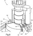
Figure 9 is a top rear perspective view of the embodiment ofFigure 6 . - With reference to the annexed drawings the preferred embodiment of the present invention will be herein described for indicative purpose and by no means as of limitation.
- Referring to
Figures 1a through 9 , there is shown a deployment or interchange mechanism in accordance with anembodiment 10 of the present invention, for deploying at least one, preferably a plurality of reflector (or sub-reflector) 12 for reconfiguration of anantenna 14, especially on an antenna mounted on aspacecraft 18, for the transmission of electromagnetic signals. InFigures 1a and1b , the top orfifth reflector 12e is a fixed reflector not connected to theinterchange mechanism 10. Eachcarrier respective reflector rotating axis 26. It is noted that, although theembodiment 10 ofFigures 1a-9 refer to moving sub-reflectors, the term reflector is used throughout the following description since it also applies to reflectors or the like. - The
interchange mechanism 10 typically includes a rotary actuator ormotor 20 having afixed section 22 for mounting on astructure 16 of theantenna 14, and amobile section 24, including ashaft 25 or the like, rotating relative to thefixed section 22 about arotation axis 26. At least one, and typically a plurality of carriers 30 support arespective reflector 12. The carriers are freely rotatably mounted on theshaft 25 viarespective bushings 28 or the like for rotation about therotation axis 26, as shown inFigure 7 . Rotation of each carrier 30 is between a respective stowed first angular position and a respective deployed second angular position. - An
arm 32 mounted on themobile section 24 carries a carrierengaging mechanism 34 that successively and releasably engages the plurality of carriers 30 and displaces them from their first angular positions to their second angular position, when thearm 32 and themobile section 24 rotate in a first direction. - The carrier engaging mechanism 34 (see
Figure 7 ) is typically a latching mechanism which successively latches to the carriers 30 at their first angular position and unlatches from the carriers 30 at the second angular position. - Typically, the latching mechanism includes a spring-loaded
detent ball 36 successively engaging acorresponding ball receptacle 38 formed into eachcarrier hard stop 40a located on thefixed section 22 ensures that thefirst carrier 30a stops at its second angular position in abutment contact therewith. Similarly, thefixed section 22 typically includes a firsthard stop respective carrier - Typically, the
fixed structure 22 includes acarrier positioning mechanism 42 that selectively and releasably engages the plurality of carriers 30 when they are at their respective second angular position for securing and maintaining them at the second angular position. - As the
ball receptacle 38 of thefirst carrier 30a is always free for engagement, thecarrier engaging mechanism 34 selectively and releasably engaging thefirst carrier 30a to successively and then simultaneously displace all the carriers 30 from their second angular position back to their first angular position, when thearm 32 and themobile section 24 rotates into a second direction opposite to the first direction. To this end, a secondhard stop 44 located on the fixedstructure 22 ensures that thelast reflector 12d stops at the first angular position in abutment contact therewith. Similarly, thelast reflector 12d serves as a hard stop for thethird reflector 12c, and so on. - Typically, the fixed
structure 22 includes a reflector positioning /detent mechanism 46 that selectively and releasably engages the plurality ofreflectors carriers 30d-30a at the first angular position. The secondhard stop 44 is typically part of or integral with thereflector positioning mechanism 46. - Preferably, when in the first angular position, each carrier 30 is in abutment contact with adjacent carriers 30.
- Each carrier 30 that has a following carrier that typically includes a
sequencing mechanism 50 to allow or permit thelatching mechanism 34 to selectively latch to the following carrier when in contact therewith. Thesequencing mechanism 50 typically includes an extension ortab 52 substantially circumferentially extending from the preceding carrier 30 into theball receptacle 38 formed into the following carrier 30 so as to prevent the spring-loadedball 36 of thelatching mechanism 34 to selectively engage theball receptacle 38 of the following carrier 30. - The
carrier positioning mechanism 42 and/or thereflector positioning mechanism 46 typically includes a spring-loaded ball detent mechanism, similar to thecarrier engaging mechanism 34, or any other mechanism such as a magnetic mechanism or the like. - When each
reflector 12 is displaced from its first angular position to its second one, themotor 20 is strong enough to overcome the resistive torque generated by thereflector positioning mechanism 46 of the correspondingreflector 12 being displaced. Similarly, when allreflectors 12 are all displaced from their second angular position back to their first one, themotor 20 is strong enough to successively overcome the resistive torque generated by thecarrier positioning mechanism 42 of each carrier 30, one at a time, since the carriers 30 are spaced from each other in the second angular position. - The present invention also provides for a
spacecraft antenna 14 comprising ainterchange mechanism 10 as described hereinabove that connects to at least one, preferably a plurality ofreflectors 12 for reconfiguration of theantenna 14. - Although not illustrated, one skilled in the art would readily realize that, without departing from the scope of the present invention, the actuator could be any non-rotary actuator, such as a linear actuator connected to a crank assembly or the like.
- Although the present invention has been described with a certain degree of particularity, it is to be understood that the disclosure has been made by way of example only and that the present invention is not limited to the features of the embodiments described and illustrated herein, but includes all variations and modifications within the scope of the invention as hereinafter claimed.
Claims (15)
- An interchange mechanism (10) for deploying at least one reflector (12) for reconfiguration of an antenna (14), said interchange mechanism (10) including:- a rotary actuator (20) having a fixed section (22) for mounting on a structure (16) of the antenna (14), and a mobile section (24) rotating relative to the fixed section (22) about a rotation axis (26);and being characterized by- at least one carrier (30) configured to support the at least one reflector (12), the at least one carrier (30) freely rotatably mounting on the fixed section (22) for rotation about the rotation axis (26) between a first angular position and a second angular position; and- an arm (32) mounted on the mobile section (24) and carrying a carrier engaging mechanism (34) configured to successively and releasably engage the at least one carrier (30) and displace the at least one carrier (30) from the first angular position to the second angular position when the arm (32) and the mobile section (24) rotate in a first direction.
- The interchange mechanism of claim 1, characterized in that the carrier engaging mechanism (34) being a latching mechanism successively latching to the at least one carrier (30) at the first angular position and unlatching from the at least one carrier (30) at the second angular position.
- The interchange mechanism of claim 2, characterized in that the latching mechanism (34) includes a spring-loaded detent ball (36) successively engaging a ball receptacle (38) formed into the at least one carrier (30).
- The interchange mechanism of claim 1, characterized in that the fixed structure (22) includes a carrier positioning mechanism (42) selectively and releasably engaging the at least one carrier (30) when at the second angular position for securing the at least one carrier (30) at the second angular position.
- The interchange mechanism of claim 1, characterized in that the carrier engaging mechanism (34) selectively and releasably engaging the at least one carrier (30) and displacing the at least one carrier (30) from the second angular position to the first angular position when the arm (32) and the mobile section (24) rotates into a second direction opposite to the first direction.
- The interchange mechanism of claim 3, characterized in that a first hard stop (40) mounted on the fixed section (22) ensures that the at least one carrier (30) stops at the second angular position in abutment contact therewith.
- The interchange mechanism of claim 6, characterized in that a second hard stop (44) mounted on the fixed section (22) ensures that the at least one carrier (30) stops at the first angular position in abutment contact therewith.
- The interchange mechanism of claim 1, characterized in that the fixed structure (22) includes a reflector positioning mechanism (46) selectively and releasably engaging the at least one reflector (12) when at the first angular position for securing the at least one reflector (12) and the at least one carrier (30) at the first angular position.
- The interchange mechanism of claim 3, characterized in that the at least one carrier (30) includes a plurality of carriers (30a,30b,30c,30d), each one of the plurality of carriers (30a,30b,30c,30d) supporting a respective one of the at least one reflectors (12a,12b,12c,12d), the plurality of carriers (30a,30b,30c,30d) being successively angularly positioned relative to one another about the rotating axis (26).
- The interchange mechanism of claim 9, characterized in that each one of the plurality of carriers (30a,30b,30c,30d) is in abutment contact with adjacent ones of the plurality of carriers (30a,30b,30c,30d) when being in the first angular position.
- The interchange mechanism of claim 9, characterized in that each one of the plurality of carriers (30a,30b,30c,30d) has at least a following one of the plurality of carriers or a preceding one of the plurality of carriers, each one of said plurality of carriers (30a,30b,30c,30d) having a following one of the plurality of carriers including a sequencing mechanism (50) permitting the carrier engaging mechanism (34) to selectively engage to the following one of the plurality of carriers (30a,30b,30c,30d) when in contact therewith.
- The interchange mechanism of claim 11, characterized in that the sequencing mechanism (50) includes an extension (52) substantially circumferentially extending from a preceding one of the plurality of carriers (30a,30b,30c,30d) into the ball receptacle (38) formed into a following one of the plurality of carriers (30a,30b,30c,30d) so as to prevent the spring-loaded ball (36) of the latching mechanism (34) to selectively engage the ball receptacle (38) formed into a following one of the plurality of carriers (30a,30b,30c,30d).
- The interchange mechanism of claim 9, characterized in that the fixed section (22) includes a respective first hard stop (40a,40b,40c,40d) for each one of the plurality of carriers (30a,30b,30c,30d) to be in abutment therewith when at the second angular position thereof, said plurality of carriers (30a,30b,30c,30d) being spaced from one another when in the second angular position.
- The interchange mechanism of claim 13, characterized in that the following one of the plurality of carriers (30a,30b,30c,30d) forming the second hard stop (44) for the preceding one of the plurality of carriers (30a,30b,30c,30d) at the corresponding first angular position thereof in abutment contact therewith.
- The interchange mechanism of claim 9, characterized in that at least one of the carrier positioning mechanism (42) and the reflector positioning mechanism (46) includes a spring-loaded ball detent mechanism.
Applications Claiming Priority (1)
| Application Number | Priority Date | Filing Date | Title |
|---|---|---|---|
| US201662350527P | 2016-06-15 | 2016-06-15 |
Publications (2)
| Publication Number | Publication Date |
|---|---|
| EP3258538A1 EP3258538A1 (en) | 2017-12-20 |
| EP3258538B1 true EP3258538B1 (en) | 2019-06-19 |
Family
ID=59067602
Family Applications (1)
| Application Number | Title | Priority Date | Filing Date |
|---|---|---|---|
| EP17176275.0A Active EP3258538B1 (en) | 2016-06-15 | 2017-06-15 | Antenna reflector interchange mechanism |
Country Status (3)
| Country | Link |
|---|---|
| US (1) | US10483638B2 (en) |
| EP (1) | EP3258538B1 (en) |
| JP (1) | JP6937174B2 (en) |
Families Citing this family (1)
| Publication number | Priority date | Publication date | Assignee | Title |
|---|---|---|---|---|
| CN109921197A (en) * | 2019-01-31 | 2019-06-21 | 西南电子技术研究所(中国电子科技集团公司第十研究所) | Beam wide-angle scanning dual reflector antenna |
Family Cites Families (8)
| Publication number | Priority date | Publication date | Assignee | Title |
|---|---|---|---|---|
| US5864320A (en) * | 1996-08-06 | 1999-01-26 | Space Systems/Loral, Inc. | Synchronous rotation dual-axis mechanical hinge assemblies |
| US5966104A (en) * | 1998-03-31 | 1999-10-12 | Hughes Electronics Corporation | Antenna having movable reflectors |
| US6239763B1 (en) * | 1999-06-29 | 2001-05-29 | Lockheed Martin Corporation | Apparatus and method for reconfiguring antenna contoured beams by switching between shaped-surface subreflectors |
| FR2874749B1 (en) | 2004-08-31 | 2006-11-24 | Cit Alcatel | REFLECTIVE NETWORK ANTENNA WITH RECONFIGURABLE SHAPE COVER AREA WITH OR WITHOUT CHARGER |
| US20060250316A1 (en) * | 2005-05-06 | 2006-11-09 | Space Systems/Loral, Inc. | Selectable subreflector configurations for antenna beam reconfigurability |
| JP2010050791A (en) * | 2008-08-22 | 2010-03-04 | Dx Antenna Co Ltd | Variable directivity antenna |
| FR2989523B1 (en) | 2012-04-13 | 2014-05-02 | Thales Sa | MULTI-REFLECTING ANTENNA FOR TELECOMMUNICATIONS SATELLITE |
| CA2831309C (en) * | 2012-12-04 | 2017-05-30 | The Boeing Company | Methods and apparatus for performing propulsion operations using electric propulsion systems |
-
2017
- 2017-06-15 EP EP17176275.0A patent/EP3258538B1/en active Active
- 2017-06-15 JP JP2017117809A patent/JP6937174B2/en active Active
- 2017-06-15 US US15/623,764 patent/US10483638B2/en active Active
Non-Patent Citations (1)
| Title |
|---|
| None * |
Also Published As
| Publication number | Publication date |
|---|---|
| US20170365922A1 (en) | 2017-12-21 |
| EP3258538A1 (en) | 2017-12-20 |
| JP6937174B2 (en) | 2021-09-22 |
| US10483638B2 (en) | 2019-11-19 |
| JP2018029331A (en) | 2018-02-22 |
Similar Documents
| Publication | Publication Date | Title |
|---|---|---|
| US8800935B2 (en) | Spacecraft payload positioning with respect to a virtual pivot point | |
| EP2996197B1 (en) | Wide scan steerable antenna | |
| US9248922B1 (en) | Reflector deployment techniques for satellites | |
| EP3444903A1 (en) | Antenna for satellite communication capable of receiving multi-band signal | |
| US20020135532A1 (en) | Triple reflector antenna deployment and storage systems | |
| CN112236901B (en) | Compact antenna phase shifter with simplified driving mechanism | |
| ES2622128T3 (en) | Antenna with mission flexibility, satellite consisting of said antenna and procedure for controlling the change of mission of said antenna | |
| US6366255B1 (en) | Main reflector and subreflector deployment and storage systems | |
| US10665929B2 (en) | Three axis reflector deployment and pointing mechanism | |
| CN110401036A (en) | Linkage Mechanism for Base Station Antenna | |
| US10483638B2 (en) | Antenna reflector interchange mechanism | |
| US10957976B2 (en) | Pedestal apparatus having antenna attached thereto capable of biaxial motion | |
| CA2812448C (en) | Multiple-reflector antenna for telecommunications satellites | |
| KR20240053560A (en) | A planar antenna system with satellite tracking function | |
| US10581130B2 (en) | Rotary joint for a rotary antenna and rotary antenna comprising such a joint | |
| CA2989657C (en) | Architecture of deployable feed cluster, compact antenna and satellite including such an architecture | |
| US10581152B2 (en) | Biaxial antenna comprising a first fixed part, a second rotary part and a rotary joint | |
| JP4480617B2 (en) | Reflector antenna | |
| US20100074612A1 (en) | Blade drive device | |
| US8384610B2 (en) | Antenna having a reflector with coverage and frequency flexibility and satellite comprising such an antenna | |
| CN114348236A (en) | Folding mechanism and unmanned aerial vehicle | |
| KR20260035779A (en) | Foldable reflector pallet and method of deploying a foldable reflector pallet | |
| US10351265B1 (en) | Rotating gimbal system | |
| US20170110794A1 (en) | Compact antenna with modular beam aperture | |
| KR20180091374A (en) | Reflector antenna including device of changing polarization of feeder antenna |
Legal Events
| Date | Code | Title | Description |
|---|---|---|---|
| PUAI | Public reference made under article 153(3) epc to a published international application that has entered the european phase |
Free format text: ORIGINAL CODE: 0009012 |
|
| STAA | Information on the status of an ep patent application or granted ep patent |
Free format text: STATUS: THE APPLICATION HAS BEEN PUBLISHED |
|
| AK | Designated contracting states |
Kind code of ref document: A1 Designated state(s): AL AT BE BG CH CY CZ DE DK EE ES FI FR GB GR HR HU IE IS IT LI LT LU LV MC MK MT NL NO PL PT RO RS SE SI SK SM TR |
|
| AX | Request for extension of the european patent |
Extension state: BA ME |
|
| STAA | Information on the status of an ep patent application or granted ep patent |
Free format text: STATUS: REQUEST FOR EXAMINATION WAS MADE |
|
| 17P | Request for examination filed |
Effective date: 20180614 |
|
| RBV | Designated contracting states (corrected) |
Designated state(s): AL AT BE BG CH CY CZ DE DK EE ES FI FR GB GR HR HU IE IS IT LI LT LU LV MC MK MT NL NO PL PT RO RS SE SI SK SM TR |
|
| RIC1 | Information provided on ipc code assigned before grant |
Ipc: H01Q 25/00 20060101ALI20181121BHEP Ipc: H01Q 19/10 20060101ALI20181121BHEP Ipc: H01Q 1/28 20060101AFI20181121BHEP |
|
| GRAP | Despatch of communication of intention to grant a patent |
Free format text: ORIGINAL CODE: EPIDOSNIGR1 |
|
| STAA | Information on the status of an ep patent application or granted ep patent |
Free format text: STATUS: GRANT OF PATENT IS INTENDED |
|
| INTG | Intention to grant announced |
Effective date: 20190104 |
|
| GRAS | Grant fee paid |
Free format text: ORIGINAL CODE: EPIDOSNIGR3 |
|
| GRAA | (expected) grant |
Free format text: ORIGINAL CODE: 0009210 |
|
| STAA | Information on the status of an ep patent application or granted ep patent |
Free format text: STATUS: THE PATENT HAS BEEN GRANTED |
|
| AK | Designated contracting states |
Kind code of ref document: B1 Designated state(s): AL AT BE BG CH CY CZ DE DK EE ES FI FR GB GR HR HU IE IS IT LI LT LU LV MC MK MT NL NO PL PT RO RS SE SI SK SM TR |
|
| REG | Reference to a national code |
Ref country code: GB Ref legal event code: FG4D |
|
| REG | Reference to a national code |
Ref country code: CH Ref legal event code: EP |
|
| REG | Reference to a national code |
Ref country code: IE Ref legal event code: FG4D |
|
| REG | Reference to a national code |
Ref country code: DE Ref legal event code: R096 Ref document number: 602017004582 Country of ref document: DE |
|
| REG | Reference to a national code |
Ref country code: AT Ref legal event code: REF Ref document number: 1146677 Country of ref document: AT Kind code of ref document: T Effective date: 20190715 |
|
| REG | Reference to a national code |
Ref country code: NL Ref legal event code: MP Effective date: 20190619 |
|
| PG25 | Lapsed in a contracting state [announced via postgrant information from national office to epo] |
Ref country code: FI Free format text: LAPSE BECAUSE OF FAILURE TO SUBMIT A TRANSLATION OF THE DESCRIPTION OR TO PAY THE FEE WITHIN THE PRESCRIBED TIME-LIMIT Effective date: 20190619 Ref country code: NO Free format text: LAPSE BECAUSE OF FAILURE TO SUBMIT A TRANSLATION OF THE DESCRIPTION OR TO PAY THE FEE WITHIN THE PRESCRIBED TIME-LIMIT Effective date: 20190919 Ref country code: HR Free format text: LAPSE BECAUSE OF FAILURE TO SUBMIT A TRANSLATION OF THE DESCRIPTION OR TO PAY THE FEE WITHIN THE PRESCRIBED TIME-LIMIT Effective date: 20190619 Ref country code: SE Free format text: LAPSE BECAUSE OF FAILURE TO SUBMIT A TRANSLATION OF THE DESCRIPTION OR TO PAY THE FEE WITHIN THE PRESCRIBED TIME-LIMIT Effective date: 20190619 Ref country code: AL Free format text: LAPSE BECAUSE OF FAILURE TO SUBMIT A TRANSLATION OF THE DESCRIPTION OR TO PAY THE FEE WITHIN THE PRESCRIBED TIME-LIMIT Effective date: 20190619 Ref country code: LT Free format text: LAPSE BECAUSE OF FAILURE TO SUBMIT A TRANSLATION OF THE DESCRIPTION OR TO PAY THE FEE WITHIN THE PRESCRIBED TIME-LIMIT Effective date: 20190619 |
|
| REG | Reference to a national code |
Ref country code: LT Ref legal event code: MG4D |
|
| PG25 | Lapsed in a contracting state [announced via postgrant information from national office to epo] |
Ref country code: BG Free format text: LAPSE BECAUSE OF FAILURE TO SUBMIT A TRANSLATION OF THE DESCRIPTION OR TO PAY THE FEE WITHIN THE PRESCRIBED TIME-LIMIT Effective date: 20190919 Ref country code: GR Free format text: LAPSE BECAUSE OF FAILURE TO SUBMIT A TRANSLATION OF THE DESCRIPTION OR TO PAY THE FEE WITHIN THE PRESCRIBED TIME-LIMIT Effective date: 20190920 Ref country code: RS Free format text: LAPSE BECAUSE OF FAILURE TO SUBMIT A TRANSLATION OF THE DESCRIPTION OR TO PAY THE FEE WITHIN THE PRESCRIBED TIME-LIMIT Effective date: 20190619 Ref country code: LV Free format text: LAPSE BECAUSE OF FAILURE TO SUBMIT A TRANSLATION OF THE DESCRIPTION OR TO PAY THE FEE WITHIN THE PRESCRIBED TIME-LIMIT Effective date: 20190619 |
|
| REG | Reference to a national code |
Ref country code: AT Ref legal event code: MK05 Ref document number: 1146677 Country of ref document: AT Kind code of ref document: T Effective date: 20190619 |
|
| PG25 | Lapsed in a contracting state [announced via postgrant information from national office to epo] |
Ref country code: SK Free format text: LAPSE BECAUSE OF FAILURE TO SUBMIT A TRANSLATION OF THE DESCRIPTION OR TO PAY THE FEE WITHIN THE PRESCRIBED TIME-LIMIT Effective date: 20190619 Ref country code: RO Free format text: LAPSE BECAUSE OF FAILURE TO SUBMIT A TRANSLATION OF THE DESCRIPTION OR TO PAY THE FEE WITHIN THE PRESCRIBED TIME-LIMIT Effective date: 20190619 Ref country code: PT Free format text: LAPSE BECAUSE OF FAILURE TO SUBMIT A TRANSLATION OF THE DESCRIPTION OR TO PAY THE FEE WITHIN THE PRESCRIBED TIME-LIMIT Effective date: 20191021 Ref country code: EE Free format text: LAPSE BECAUSE OF FAILURE TO SUBMIT A TRANSLATION OF THE DESCRIPTION OR TO PAY THE FEE WITHIN THE PRESCRIBED TIME-LIMIT Effective date: 20190619 Ref country code: AT Free format text: LAPSE BECAUSE OF FAILURE TO SUBMIT A TRANSLATION OF THE DESCRIPTION OR TO PAY THE FEE WITHIN THE PRESCRIBED TIME-LIMIT Effective date: 20190619 Ref country code: NL Free format text: LAPSE BECAUSE OF FAILURE TO SUBMIT A TRANSLATION OF THE DESCRIPTION OR TO PAY THE FEE WITHIN THE PRESCRIBED TIME-LIMIT Effective date: 20190619 Ref country code: CZ Free format text: LAPSE BECAUSE OF FAILURE TO SUBMIT A TRANSLATION OF THE DESCRIPTION OR TO PAY THE FEE WITHIN THE PRESCRIBED TIME-LIMIT Effective date: 20190619 |
|
| PG25 | Lapsed in a contracting state [announced via postgrant information from national office to epo] |
Ref country code: SM Free format text: LAPSE BECAUSE OF FAILURE TO SUBMIT A TRANSLATION OF THE DESCRIPTION OR TO PAY THE FEE WITHIN THE PRESCRIBED TIME-LIMIT Effective date: 20190619 Ref country code: IT Free format text: LAPSE BECAUSE OF FAILURE TO SUBMIT A TRANSLATION OF THE DESCRIPTION OR TO PAY THE FEE WITHIN THE PRESCRIBED TIME-LIMIT Effective date: 20190619 Ref country code: IS Free format text: LAPSE BECAUSE OF FAILURE TO SUBMIT A TRANSLATION OF THE DESCRIPTION OR TO PAY THE FEE WITHIN THE PRESCRIBED TIME-LIMIT Effective date: 20191019 |
|
| PG25 | Lapsed in a contracting state [announced via postgrant information from national office to epo] |
Ref country code: TR Free format text: LAPSE BECAUSE OF FAILURE TO SUBMIT A TRANSLATION OF THE DESCRIPTION OR TO PAY THE FEE WITHIN THE PRESCRIBED TIME-LIMIT Effective date: 20190619 |
|
| PG25 | Lapsed in a contracting state [announced via postgrant information from national office to epo] |
Ref country code: PL Free format text: LAPSE BECAUSE OF FAILURE TO SUBMIT A TRANSLATION OF THE DESCRIPTION OR TO PAY THE FEE WITHIN THE PRESCRIBED TIME-LIMIT Effective date: 20190619 Ref country code: DK Free format text: LAPSE BECAUSE OF FAILURE TO SUBMIT A TRANSLATION OF THE DESCRIPTION OR TO PAY THE FEE WITHIN THE PRESCRIBED TIME-LIMIT Effective date: 20190619 |
|
| PG25 | Lapsed in a contracting state [announced via postgrant information from national office to epo] |
Ref country code: IS Free format text: LAPSE BECAUSE OF FAILURE TO SUBMIT A TRANSLATION OF THE DESCRIPTION OR TO PAY THE FEE WITHIN THE PRESCRIBED TIME-LIMIT Effective date: 20200224 |
|
| REG | Reference to a national code |
Ref country code: DE Ref legal event code: R097 Ref document number: 602017004582 Country of ref document: DE |
|
| PLBE | No opposition filed within time limit |
Free format text: ORIGINAL CODE: 0009261 |
|
| STAA | Information on the status of an ep patent application or granted ep patent |
Free format text: STATUS: NO OPPOSITION FILED WITHIN TIME LIMIT |
|
| PG2D | Information on lapse in contracting state deleted |
Ref country code: IS |
|
| 26N | No opposition filed |
Effective date: 20200603 |
|
| PG25 | Lapsed in a contracting state [announced via postgrant information from national office to epo] |
Ref country code: SI Free format text: LAPSE BECAUSE OF FAILURE TO SUBMIT A TRANSLATION OF THE DESCRIPTION OR TO PAY THE FEE WITHIN THE PRESCRIBED TIME-LIMIT Effective date: 20190619 |
|
| PG25 | Lapsed in a contracting state [announced via postgrant information from national office to epo] |
Ref country code: ES Free format text: LAPSE BECAUSE OF FAILURE TO SUBMIT A TRANSLATION OF THE DESCRIPTION OR TO PAY THE FEE WITHIN THE PRESCRIBED TIME-LIMIT Effective date: 20190619 |
|
| REG | Reference to a national code |
Ref country code: DE Ref legal event code: R119 Ref document number: 602017004582 Country of ref document: DE |
|
| PG25 | Lapsed in a contracting state [announced via postgrant information from national office to epo] |
Ref country code: MC Free format text: LAPSE BECAUSE OF FAILURE TO SUBMIT A TRANSLATION OF THE DESCRIPTION OR TO PAY THE FEE WITHIN THE PRESCRIBED TIME-LIMIT Effective date: 20190619 |
|
| REG | Reference to a national code |
Ref country code: CH Ref legal event code: PL |
|
| PG25 | Lapsed in a contracting state [announced via postgrant information from national office to epo] |
Ref country code: LU Free format text: LAPSE BECAUSE OF NON-PAYMENT OF DUE FEES Effective date: 20200615 |
|
| REG | Reference to a national code |
Ref country code: BE Ref legal event code: MM Effective date: 20200630 |
|
| PG25 | Lapsed in a contracting state [announced via postgrant information from national office to epo] |
Ref country code: IE Free format text: LAPSE BECAUSE OF NON-PAYMENT OF DUE FEES Effective date: 20200615 Ref country code: CH Free format text: LAPSE BECAUSE OF NON-PAYMENT OF DUE FEES Effective date: 20200630 Ref country code: LI Free format text: LAPSE BECAUSE OF NON-PAYMENT OF DUE FEES Effective date: 20200630 |
|
| PG25 | Lapsed in a contracting state [announced via postgrant information from national office to epo] |
Ref country code: BE Free format text: LAPSE BECAUSE OF NON-PAYMENT OF DUE FEES Effective date: 20200630 Ref country code: DE Free format text: LAPSE BECAUSE OF NON-PAYMENT OF DUE FEES Effective date: 20210101 |
|
| GBPC | Gb: european patent ceased through non-payment of renewal fee |
Effective date: 20210615 |
|
| PG25 | Lapsed in a contracting state [announced via postgrant information from national office to epo] |
Ref country code: GB Free format text: LAPSE BECAUSE OF NON-PAYMENT OF DUE FEES Effective date: 20210615 |
|
| PG25 | Lapsed in a contracting state [announced via postgrant information from national office to epo] |
Ref country code: MT Free format text: LAPSE BECAUSE OF FAILURE TO SUBMIT A TRANSLATION OF THE DESCRIPTION OR TO PAY THE FEE WITHIN THE PRESCRIBED TIME-LIMIT Effective date: 20190619 Ref country code: CY Free format text: LAPSE BECAUSE OF FAILURE TO SUBMIT A TRANSLATION OF THE DESCRIPTION OR TO PAY THE FEE WITHIN THE PRESCRIBED TIME-LIMIT Effective date: 20190619 |
|
| PG25 | Lapsed in a contracting state [announced via postgrant information from national office to epo] |
Ref country code: MK Free format text: LAPSE BECAUSE OF FAILURE TO SUBMIT A TRANSLATION OF THE DESCRIPTION OR TO PAY THE FEE WITHIN THE PRESCRIBED TIME-LIMIT Effective date: 20190619 |
|
| PGFP | Annual fee paid to national office [announced via postgrant information from national office to epo] |
Ref country code: FR Payment date: 20250627 Year of fee payment: 9 |