EP3258444B1 - Reconstructing an image - Google Patents
Reconstructing an image Download PDFInfo
- Publication number
- EP3258444B1 EP3258444B1 EP17175962.4A EP17175962A EP3258444B1 EP 3258444 B1 EP3258444 B1 EP 3258444B1 EP 17175962 A EP17175962 A EP 17175962A EP 3258444 B1 EP3258444 B1 EP 3258444B1
- Authority
- EP
- European Patent Office
- Prior art keywords
- axial position
- coincidence
- clock signal
- master clock
- scanning bed
- Prior art date
- Legal status (The legal status is an assumption and is not a legal conclusion. Google has not performed a legal analysis and makes no representation as to the accuracy of the status listed.)
- Active
Links
Images



Classifications
-
- G—PHYSICS
- G06—COMPUTING OR CALCULATING; COUNTING
- G06T—IMAGE DATA PROCESSING OR GENERATION, IN GENERAL
- G06T12/00—Tomographic reconstruction from projections
-
- A—HUMAN NECESSITIES
- A61—MEDICAL OR VETERINARY SCIENCE; HYGIENE
- A61B—DIAGNOSIS; SURGERY; IDENTIFICATION
- A61B6/00—Apparatus or devices for radiation diagnosis; Apparatus or devices for radiation diagnosis combined with radiation therapy equipment
- A61B6/02—Arrangements for diagnosis sequentially in different planes; Stereoscopic radiation diagnosis
- A61B6/03—Computed tomography [CT]
- A61B6/037—Emission tomography
-
- A—HUMAN NECESSITIES
- A61—MEDICAL OR VETERINARY SCIENCE; HYGIENE
- A61B—DIAGNOSIS; SURGERY; IDENTIFICATION
- A61B6/00—Apparatus or devices for radiation diagnosis; Apparatus or devices for radiation diagnosis combined with radiation therapy equipment
- A61B6/52—Devices using data or image processing specially adapted for radiation diagnosis
-
- G—PHYSICS
- G06—COMPUTING OR CALCULATING; COUNTING
- G06T—IMAGE DATA PROCESSING OR GENERATION, IN GENERAL
- G06T12/00—Tomographic reconstruction from projections
- G06T12/10—Image preprocessing, e.g. calibration, positioning of sources or scatter correction
-
- G—PHYSICS
- G06—COMPUTING OR CALCULATING; COUNTING
- G06T—IMAGE DATA PROCESSING OR GENERATION, IN GENERAL
- G06T2210/00—Indexing scheme for image generation or computer graphics
- G06T2210/41—Medical
-
- G—PHYSICS
- G06—COMPUTING OR CALCULATING; COUNTING
- G06T—IMAGE DATA PROCESSING OR GENERATION, IN GENERAL
- G06T2211/00—Image generation
- G06T2211/40—Computed tomography
- G06T2211/424—Iterative
Definitions
- the present disclosure relates to reconstructing an image.
- PET Positron Emission Tomography
- its axial coverage may be not relatively large, e.g., about 15 to 20 cm.
- a scanning of a large scale for example, a whole body scan of a subject
- the subject lying on a scanning bed may be scanned by changing the position of the bed in a step-by-step way.
- a plurality of scanned images may be reconstructed respectively.
- the plurality of reconstructed images may be combined together to form a whole body PET image.
- a positron emission tomography (PET) system includes a memory, a subject support, a categorizing unit, and a reconstruction unit.
- the memory continuously records detected coincident event pairs detected by PET detectors.
- the subject support supports a subject and moves in a continuous movement through a field of view of the PET detectors.
- the categorizing unit categorizes the recorded coincident pairs into each of a plurality of spatially defined virtual frame.
- the reconstruction unit reconstructs the categorized coincident pairs of each virtual frame into a frame image and combines the frame images into a common elongated image.
- first, second, third, etc. in the present disclosure, this information should not be limited to these terms. These terms are used only to distinguish the same type of information from each other.
- first information may also be referred to as the second information without departing from the scope of the present disclosure, and similarly, the second information may also be referred to as the first information.
- the used word "if” may be interpreted as "when” or “as” or "in response to”.
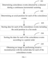
- FIG. 1 is a flowchart of a method of reconstructing an image based on a list mode according to an example of the present disclosure.
- the medical device of the present disclosure may take a PET device as an example and the method of reconstructing an image includes the following blocks 101-105.
- coincidence events detected by a detector during a continuous incremental scanning are determined.
- a determining method is as follows: during the continuous incremental scanning, when the detector in a front-end system (in the present disclosure, taking the front-end system including a clock system, a scanning bed system and a detector system as an example, wherein the detector system may also be referred to as a gantry system) receives a master clock signal, it may begin to collect a pair of photons and mark time information of the pair of photons detected by the detector.
- the master clock signal may be given by the clock system.
- the clock system may provide the master clock signal for the front-end system to work, and simultaneously output the master clock signal to the detector system, the scanning bed system and the like of the front-end system to use. In this way, the detector system and the scanning bed system may use the same master clock signal.
- the master clock signal may also be referred to as a synchronous clock.
- a coincidence event condition for example, a coincidence time window. If yes, it may be determined that a coincidence event is detected; otherwise, it may be determined that a non-coincidence event is detected.
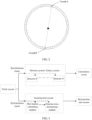
- two back-to-back photon signals may be emitted, which may be detected by a crystal A and a crystal B of the detector, respectively.
- FIG. 2 it is a schematic diagram of a pair of photons detected by the crystal A and the crystal B of the detector according to an example of the present disclosure.
- a line connecting the crystal A and the crystal B may be called a line of response.
- the positron annihilation event may be considered a coincidence event; otherwise, it may be called a non-coincidence event.
- Data for each of the coincidence events may include four parameters: an axial slant angle index, a radial angle index, an axial position, and a radial position index.
- an axial slant angle index a radial angle index
- an axial position a radial position index
- a radial position index a radial position index
- an axial position of a coincidence event in the present disclosure is an actual position of the scanning bed.
- an axial position for each of the coincidence events is determined.
- a method of determining an axial position for each of the coincidence events is as follows.
- the scanning bed system in the front-end system receives the master clock signal
- the scanning bed may move continuously in accordance with a setting requirement and a current axial position of the scanning bed may be determined according to a number of pulses of the master clock signals.
- An axial position of a coincidence event may be determined with respect to the scanning bed.
- the axial position of the coincidence event may indicate an axial position of the scanning bed when the detector detects the coincidence event. Therefore, in the present disclosure, the axial position of the coincidence event may be regarded as an actual axial position of the scanning bed.
- the clock system may provide the master clock signal for the front-end system to work, and divide the master clock signal into two streams, thereby simultaneously providing the two streams to detector system (i.e., the gantry system) and the scanning bed system to use.
- detector system i.e., the gantry system
- FIG. 3 it is a structure schematic diagram of the front-end system according to an example of the present disclosure.
- the entire front-end system may take the master clock signal provided by the clock system as a reference to mark time information.
- the operation may be as follows.
- a PET device that supports detecting coincidence event during the continuous incremental scanning may obtain an axial position of the scanning bed in real-time.
- data for each of the coincidence events including the axial position is stored in a list mode.
- Each of the coincidence events including the axial position is stored in the list mode in a storage medium such as a memory, a magnetic disk and the like.
- the list mode is as follows.
- Event 1 includes [an axial slant angle index, a radial angle index, an axial position, and a radial position index].
- Event 2 includes [an axial slant angle index, a radial angle index, an axial position, and a radial position index].
- Event N includes [an axial slant angle index, a radial angle index, an axial position, and a radial position index].
- an axial position for each of the above events is an actual axial position of the scanning bed.
- the actual axial position the scanning bed is a float.
- the list mode in the present disclosure may effectively ensure the accuracy of an axial position for each of the coincidence events.
- the size of the memory occupied by each of the coincidence events increases relatively, because of the sparseness of the data itself, it still has a greater advantage over another list mode in terms of storing and computing redundancy.
- the data for each of the coincidence events is sorted according to a spatial order.
- the data for each of the coincidence events stored in the list mode is sorted according to a spatial order.
- the sorting may be performed based on a projection algorithm of an axial position.
- a projection algorithm is well known to those skilled in the art.
- a forward projection of a three-dimensional multi-slice image is performed along a spatial unit vector ( ⁇ , ⁇ )
- a two-dimensional projection may be obtained.
- FIG. 5 it is a schematic diagram of spatial coordinate rotation in a projection algorithm according to an example of the present disclosure.
- a pixel position of the three-dimensional image may be represented by a coordinate (x, y, z).
- a direction of a spatial unit vector may be represented by an axial slant angle ⁇ and a radial angle ⁇ in the list mode.
- the two-dimensional projection may be represented by a coordinate system s-t-z'.
- z' here may not only represent a normal vector of the s-t plane, but also may be used as a determining method for a distance between a pixel point and a centre of a Field of View (FOV).
- FOV Field of View
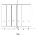
- an axial position of a coincidence event as shown in FIG. 6 may be recorded at Z 3 (in the present disclosure, the axial position of the coincidence event may be recorded at Z x ).
- FIG. 6 is a schematic diagram of a projection algorithm according to an example of the present disclosure. This may result in an error of (Z 3 -Z X ) * slice thickness in the axial position of the coincidence event. In a forward projection and a backward projection, this coincidence event may be recorded at Z 3 and the reconstructed image may have an axial deviation.
- the axial deviation of the axial position index solution may be estimated by spatial geometry herein.
- the axial deviation of the axial position index solution may be represented by a variable t, which may be denoted as
- the axial position of the coincidence event is not a value estimated based on an index, but an actual determined value.
- this coincidence event is related to both Z 2 and Z 3 .
- a relation weight between this coincidence event and an image slice i 2 is (Z 3 -Z X )/(Z 3 -Z 2 ) and the relation weight may be allocated to Z 2 ; and a relation weight between this coincidence event and an image slice is is (Z X -Z 2 )/(Z 3 -Z 2 ) and the relation weight may be allocated to Z 3 .
- 0. Therefore, the technical solution provided by the present disclosure does not have an error in terms of precision, thereby improving the quality of the reconstructed image.
- the axial position projection manner is not limited to the above manner.
- the same operation may be completed by a bilinear interpolation, a polynomial interpolation and so on.
- an image is obtained by performing iterative reconstruction with the sorted data for each of the coincidence events.
- the axial position for each of the coincidence events may be recorded one by one by an improved list mode, a projection method and a method of obtaining an actual axial position corresponding to the scanning bed, thereby fundamentally avoiding the possibility of introducing an axial error so that position and shape of the reconstructed image are more accurate.
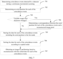
- FIG. 7 is a flow diagram of a method of reconstructing PET image according to another example of the present disclosure.
- the method includes the following blocks 701-707.
- coincidence events detected by a detector during a continuous incremental scanning may be determined.
- an axial position for each of the coincidence events may be determined.
- Blocks 701 and 702 are the same as blocks 101 and 102, respectively, and please see above for more detail, which will not be described again here.
- block 703 it may be determined whether a variable image slice thickness changes or not. If yes, block 704 may be performed; otherwise, block 705 may be performed directly.
- variable image slice thickness it may be determined whether the inputted variable image slice thickness is the same as a default variable image slice thickness. If yes, it may be determined that the variable image slice thickness does not change; otherwise, it may be determined that the variable image slice thickness changes.
- a correspondence between the axial position for each of the coincidence events and a reconstructed image pixel may be determined.
- the variable image slice thickness and an axial position for each of the slices may be determined first.
- the axial position for each of the slices may be a center for each of the slices. For example, if the variable image slice thickness is 5 mm, an axial position of a first slice may be 2.5 mm, an axial position of a second slice may be 7.5 mm. Then, the axial position for each of the coincidence events may be projected onto an axial position for each of the slices in the reconstructed image to obtain the correspondence between the axial position for each of the coincidence events and a reconstructed image pixel.
- data for each of the coincidence events including the axial position may be stored in the list mode.
- the data for each of the coincidence events stored in the list mode may be sorted according to a spatial order.
- a PET image may be obtained by performing iterative reconstruction with the sorted data for each of the sorted coincidence events.
- the image slice thickness since the axial position for each of the coincidence events is an actual value, the image slice thickness may be any size in theory.
- the present disclosure further provides a device for reconstructing an image according to an example.
- the device for reconstructing an image provided in the present disclosure may be applied to a medical device.
- Device examples may be implemented by software, or may be implemented by hardware or by a combination of hardware and software.
- FIG. 8 it is a hardware structure diagram of a device for reconstructing an image according to an example of the present disclosure.
- the device for reconstructing an image may further include other hardware according to actual functions, and detailed description is omitted for brevity.
- the machine-readable storage medium 830 may be a Read-Only Memory (ROM), a volatile memory, a non-volatile memory, a flash memory, a storage drive (e.g., a hard disk drive), a solid state drive , any type of storage disks (such as an optical disk, a DVD, etc.), or a similar storage medium, or a combination thereof.
- ROM Read-Only Memory
- volatile memory e.g., a volatile memory
- non-volatile memory e.g., a flash memory
- a storage drive e.g., a hard disk drive
- solid state drive e.g., any type of storage disks (such as an optical disk, a DVD, etc.), or a similar storage medium, or a combination thereof.
- the machine-readable storage medium 830 may store a control logic for reconstructing an image.
- the control logic for reconstructing an image not being part of the present invention may include a first determining module 91, a second determining module 92, a storing module 93, a sorting module 94 and a reconstructing module 95.
- the first determining module 91 may be configured to determine coincidence events detected by a detector during a continuous incremental scanning.
- the second determining module 92 may be configured to determine an axial position for each of the coincidence events.
- the storing module 93 may be configured to store data for each of the coincidence events including the axial position in a list mode.
- the sorting module 94 may be configured to sort the data for each of the coincidence events according to a spatial order.
- the reconstructing module 95 may be configured to obtaining an image by performing iteratively reconstruction with the sorted data for each of the coincidence events.
- the first determining module includes a first determining sub-module, a detecting sub-module, a marking sub-module, a second determining sub-module and a third determining sub-module.
- the first determining sub-module may be configured to determine whether the detector receives a master clock signal during a continuous incremental scanning or not.
- the detecting sub-module may be configured to begin detecting a pair of photons when the first determining sub-module determines that the detector has received the master clock signal.
- the marking sub-module may be configured to mark time information on the pair of photons detected by the detecting sub-module.
- the second determining sub-module may be configured to determine whether the marked time information for the pair of photons meets a coincidence time window or not. When the marked time information for the pair of photons meets a coincidence time window, the second determining sub-module may determine that a coincidence event is detected.
- the second determining module may include a determining sub-module.
- the determining sub-module may be configured to determine an actual axial position of the scanning bed based on a master clock signal and the axial position for each of the coincidence events according to the actual axial position of the scanning bed.
- the sorting module may be configured to sort the data for each of the coincidence events stored in the list mode according to a spatial order.
- control logic for reconstructing an image may further include a third determining module.
- the third determining module may be configured to determine whether a variable image slice thickness changes or not; if yes, the storing module 93 may be configured to store the data for each of the coincidence events including the axial position in the list mode when a correspondence between the axial position for each of the coincidence events and a reconstructed image pixel; and if not, the storing module 93 may be directly configured to store the data for each of the coincidence events including the axial position in the list mode.
- control logic of the present disclosure may be understood as machine executable instructions stored in the machine readable storage medium 830.
- processor 810 of the device for reconstructing an image in the present disclosure executes the control logic
- the processor 810 may execute corresponding machine executable instructions of the control logic stored on the machine readable storage medium 830 to:
- the machine-executable instructions when determining coincidence events detected by the detector during the continuous incremental scanning, the machine-executable instructions cause the processor to mark time information of a pair of photons detected by the detector during the continuous incremental scanning according to a master clock signal; and determine that a coincidence event is detected when the marked time information for the pair of photons meets a coincidence time window.
- the machine-executable instructions when determining determining the axial position for each of the coincidence events, cause the processor to determine an actual axial position of the scanning bed based on a master clock signal and determine the axial position for each of the coincidence events according to the actual axial position of the scanning bed.
- the machine-executable instructions when determining the actual axial position of the scanning bed based on the master clock signal, the machine-executable instructions cause the processor to determine an axial position of the scanning bed based on a number of pulses of the master clock signal; determine a time difference between a first timing at which the detector detects the coincidence event and a second timing for a rising edge of the master clock signal which is the nearest to the first timing; and obtain the actual axial position of the scanning bed by correcting the axial position of the scanning bed according to the time difference.
- the machine-executable instructions when sorting the data for each of the coincidence events according to the spatial order, the machine-executable instructions cause the processor to sort the data for each of the coincidence events with a projection algorithm.
- the machine-executable instruction further causes the processor to: determine whether a variable image slice thickness changes or not; store the data for each of the coincidence events including the axial position in the list mode when a correspondence between the axial position for each of the coincidence events and a reconstructed image pixel is determined in a case that the variable image slice thickness changes; and store the data for each of the coincidence events including the axial position in the list mode in a case that the variable image slice thickness does not change.
- the data for each of the coincidence events includes an axial slant angle index, a radial angle index, the axial position and a radial position index of the coincidence event.
- the detector in the present embodiment may be a PET detector and a reconstructed image may be a PET image.
- the correlations therebetween may refer to part of the method examples.
- the device examples described above are merely illustrative, wherein units described as separate components may be or may not be physically separated, and components displayed as units may be or may not be physical units, i.e., may be located in one place, or may be distributed to a plurality of network elements. Part or all of the modules may be selected according to actual requirements to achieve the purpose of the solution of the present disclosure. Those skilled in the art will understand and implement it without creative work.
Landscapes
- Engineering & Computer Science (AREA)
- Physics & Mathematics (AREA)
- Health & Medical Sciences (AREA)
- Life Sciences & Earth Sciences (AREA)
- General Physics & Mathematics (AREA)
- Theoretical Computer Science (AREA)
- Medical Informatics (AREA)
- Pathology (AREA)
- Public Health (AREA)
- Biophysics (AREA)
- Nuclear Medicine, Radiotherapy & Molecular Imaging (AREA)
- Optics & Photonics (AREA)
- Veterinary Medicine (AREA)
- Radiology & Medical Imaging (AREA)
- Biomedical Technology (AREA)
- Heart & Thoracic Surgery (AREA)
- Molecular Biology (AREA)
- Surgery (AREA)
- Animal Behavior & Ethology (AREA)
- General Health & Medical Sciences (AREA)
- High Energy & Nuclear Physics (AREA)
- Computer Vision & Pattern Recognition (AREA)
- Nuclear Medicine (AREA)
- Apparatus For Radiation Diagnosis (AREA)
Description
- The present disclosure relates to reconstructing an image.
- As a Positron Emission Tomography (PET) device is limited by the factors such as hardware processing performance and manufacturing costs, its axial coverage may be not relatively large, e.g., about 15 to 20 cm. When a scanning of a large scale, for example, a whole body scan of a subject, is performed in an axial field of view, the subject lying on a scanning bed may be scanned by changing the position of the bed in a step-by-step way. Then a plurality of scanned images may be reconstructed respectively. Finally the plurality of reconstructed images may be combined together to form a whole body PET image. However, because axial sensitivity of data is not consistent during step scanning, an axial signal-to-noise ratio of the PET image may have a large fluctuation and image noise of an overlapping part may be high.
WO 2014/024099 describes a positron emission tomography (PET) system includes a memory, a subject support, a categorizing unit, and a reconstruction unit. The memory continuously records detected coincident event pairs detected by PET detectors. The subject support supports a subject and moves in a continuous movement through a field of view of the PET detectors. The categorizing unit categorizes the recorded coincident pairs into each of a plurality of spatially defined virtual frame. The reconstruction unit reconstructs the categorized coincident pairs of each virtual frame into a frame image and combines the frame images into a common elongated image. - Therefore, how to improve the quality of the PET reconstructed image may be a technical problem to be solved at present.
- The invention is set out in the appended set of claims.
- The details of one or more embodiments of the subject matter described in the present disclosure are set forth in the accompanying drawings and description below. Other features, aspects, and advantages of the subject matter will become apparent from the description, the drawings, and the claims. Features of the present disclosure are illustrated by way of example and not limited in the following figures, in which like numerals indicate like elements.
-
FIG. 1 is a flowchart of a method of reconstructing an image according to an example of the present disclosure. -
FIG. 2 is a schematic diagram of a pair of photons detected by a crystal A and a crystal B of a detector according to an example of the present disclosure. -
FIG. 3 is a structure schematic diagram of a front-end system according to an example of the present disclosure. -
FIG. 4 is a schematic diagram of a method of determining an actual axial position of a scanning bed according to an example of the present disclosure. -
FIG. 5 is a schematic diagram of a spatial coordinate rotation according to an example of the present disclosure. -
FIG. 6 is a schematic diagram of a projection algorithm according to an example of the present disclosure. -
FIG. 7 is a flow diagram of a method of reconstructing an image according to in another example of the present disclosure. -
FIG. 8 is a hardware structure diagram of a device for reconstructing an image according to an example of the present disclosure. -
FIG. 9 is a block diagram of a control logic for reconstructing an image according to an example of the present disclosure not being part of the present invention. - Exemplary examples will be described in detail herein, examples of which may be illustrated in the accompanying drawings. The following description refers to the accompanying drawings in which same numbers in the different drawings may represent the same or similar elements unless otherwise represented. The implementations described in the following exemplary examples do not represent all implementations consistent with the present disclosure. In contrast, they are merely examples of devices and methods consistent with some aspects of the present disclosure as recited in the appended claims.
- The terms used in the present disclosure is for the purpose of describing particular examples only, and is not intended to limit the present disclosure. The singular forms such as "a", "said", and "the" used in the present disclosure and the appended claims are also intended to include plural forms, unless otherwise meaning is clearly indicated in the context. It may be further understood that the term "and/or" as used herein refers to any or all possible combinations that include one or more associated listed items.
- It may be understood that although various information may be described by using the terms such as first, second, third, etc. in the present disclosure, this information should not be limited to these terms. These terms are used only to distinguish the same type of information from each other. For example, the first information may also be referred to as the second information without departing from the scope of the present disclosure, and similarly, the second information may also be referred to as the first information. Depending on the context, in addition, the used word "if" may be interpreted as "when" or "as" or "in response to".
- Refer to
FIG. 1 , which is a flowchart of a method of reconstructing an image based on a list mode according to an example of the present disclosure. The medical device of the present disclosure may take a PET device as an example and the method of reconstructing an image includes the following blocks 101-105. - At
block 101, coincidence events detected by a detector during a continuous incremental scanning are determined. - In an example, a determining method is as follows: during the continuous incremental scanning, when the detector in a front-end system (in the present disclosure, taking the front-end system including a clock system, a scanning bed system and a detector system as an example, wherein the detector system may also be referred to as a gantry system) receives a master clock signal, it may begin to collect a pair of photons and mark time information of the pair of photons detected by the detector.
- Herein the master clock signal may be given by the clock system. For example, the clock system may provide the master clock signal for the front-end system to work, and simultaneously output the master clock signal to the detector system, the scanning bed system and the like of the front-end system to use. In this way, the detector system and the scanning bed system may use the same master clock signal. In the example, the master clock signal may also be referred to as a synchronous clock.
- Then, it may be determined whether the time information of the pair of photons detected by the detector meets a coincidence event condition, for example, a coincidence time window. If yes, it may be determined that a coincidence event is detected; otherwise, it may be determined that a non-coincidence event is detected.
- In an example, if a positron annihilation event occurs in the detector of the detector system, two back-to-back photon signals (i.e., a pair of photons) may be emitted, which may be detected by a crystal A and a crystal B of the detector, respectively. As shown in
FIG. 2 , it is a schematic diagram of a pair of photons detected by the crystal A and the crystal B of the detector according to an example of the present disclosure. Herein, a line connecting the crystal A and the crystal B may be called a line of response. If a back-end server determines that a time difference in which the two detected photon signals arrive at the detector is within the coincidence time window (generally less than a few nanoseconds), the positron annihilation event may be considered a coincidence event; otherwise, it may be called a non-coincidence event. - Data for each of the coincidence events may include four parameters: an axial slant angle index, a radial angle index, an axial position, and a radial position index. Herein, it is well known to those skilled in the art to determine the axial slant angle index, the radial angle index and the radial position index, and further description is omitted for brevity.
- It should be noted that an axial position of a coincidence event in the present disclosure is an actual position of the scanning bed.
- At
block 102, an axial position for each of the coincidence events is determined. - A method of determining an axial position for each of the coincidence events is as follows. When the scanning bed system in the front-end system receives the master clock signal, the scanning bed may move continuously in accordance with a setting requirement and a current axial position of the scanning bed may be determined according to a number of pulses of the master clock signals. An axial position of a coincidence event may be determined with respect to the scanning bed. For example, the axial position of the coincidence event may indicate an axial position of the scanning bed when the detector detects the coincidence event. Therefore, in the present disclosure, the axial position of the coincidence event may be regarded as an actual axial position of the scanning bed.
- In an example, the clock system may provide the master clock signal for the front-end system to work, and divide the master clock signal into two streams, thereby simultaneously providing the two streams to detector system (i.e., the gantry system) and the scanning bed system to use. As shown in
FIG. 3 , it is a structure schematic diagram of the front-end system according to an example of the present disclosure. - The entire front-end system may take the master clock signal provided by the clock system as a reference to mark time information. The operation may be as follows.
- 1) When the entire front-end system is powered on, the clock system may start to work first and provide the master clock signal required by various sub-systems (including the detector system, the scanning bed system and the like) when receiving a command to begin scanning.
- 2) When receiving the master clock signal, the detector system may begin detecting a pair of photons and marking time information.
When the detector in the detector system detects a pair of photons, it measures a time difference between a first timing at which the pair of photon pair is detected and a second timing for a rising edge of the master clock signal which is the nearest to the first timing. This time difference plus the second timing for the rising edge of the master clock signal is a timing at which the photon pair is detected. The time difference may be used to synchronize the scanning bed system and the detector system, mark the timing for each of the coincidence events and determine an axial position of each of the coincidence events. - 3) When receiving the master clock signal, a bed motion controlling module in the scanning bed system may control the scanning bed to move according to the setting requirement.
In an example, a distance travelled by the scanning bed each pulse of the master clock signal may be set in advance. For example, it may be set that the scanning bed moves 1 mm every 10 pulses of the master clock signal. When the bed motion controlling module receives the master clock signal, it may control the scanning bed to move. For example, the scanning bed may move 0.1 mm each pulse of the master clock signal. A position-time determining module may determine a current axial position of the scanning bed by recording a number of pulses of the master clock signal. All current axial positions of the scanning bed during the movement may be referred to as a bed position data stream. For example, a current axial position of the scanning bed may be obtained in a way that the number of pulses of the master clock signal is multiplied by the distance travelled by the scanning bed in a single pulse of the master clock signal. - 4) During a synchronization process, an uploaded coincidence event may include relevant information of the master clock signal, i.e., each of the coincidence events may correspond to a timing determined from the master clock signal. At the same time, a correction table of scanning bed position-coincidence event timing may be obtained according to position/master clock signal provided by the scanning bed system. The correction table may be a time offset, for example, the time difference mentioned in 2). The correction table may be used to correct an axial position of the scanning bed. There may be a time difference between a first timing at which the detector detects a coincidence event and a second timing for a rising edge of the master clock signal which is the nearest to the first timing. In this way, there may be a distance difference between an axial position of the coincidence event and an actual position of the scanning bed corresponding to the coincidence event. In order to synchronize both of them, an axial position of the scanning bed may be corrected. As shown in
FIG. 4 , it is a schematic diagram of a method of determining an actual axial position of the scanning bed according to an example of the present disclosure. - In an example, a PET device that supports detecting coincidence event during the continuous incremental scanning may obtain an axial position of the scanning bed in real-time.
- At
block 103, data for each of the coincidence events including the axial position is stored in a list mode. - Each of the coincidence events including the axial position is stored in the list mode in a storage medium such as a memory, a magnetic disk and the like. Herein, the list mode is as follows.
- Event 1 includes [an axial slant angle index, a radial angle index, an axial position, and a radial position index].
- Event 2 includes [an axial slant angle index, a radial angle index, an axial position, and a radial position index].
- Event N includes [an axial slant angle index, a radial angle index, an axial position, and a radial position index].
- It should be noted that an axial position for each of the above events is an actual axial position of the scanning bed. The actual axial position the scanning bed is a float.
- Compared with another list mode [an axial slant angle index, a radial angle index, an axial position index, and a radial position index], since a third dimension parameter is changed from a discrete axial position index to an actual axial position corresponding to the current scanning bed while the event is recorded, the list mode in the present disclosure may effectively ensure the accuracy of an axial position for each of the coincidence events. Although the size of the memory occupied by each of the coincidence events increases relatively, because of the sparseness of the data itself, it still has a greater advantage over another list mode in terms of storing and computing redundancy.
- At
block 104, the data for each of the coincidence events is sorted according to a spatial order. - In the present disclosure, the data for each of the coincidence events stored in the list mode is sorted according to a spatial order. Where, the sorting may be performed based on a projection algorithm of an axial position.
- A projection algorithm is well known to those skilled in the art. When a forward projection of a three-dimensional multi-slice image is performed along a spatial unit vector (ϕ,θ), a two-dimensional projection may be obtained. As shown in
FIG. 5 , it is a schematic diagram of spatial coordinate rotation in a projection algorithm according to an example of the present disclosure. A pixel position of the three-dimensional image may be represented by a coordinate (x, y, z). A direction of a spatial unit vector may be represented by an axial slant angle θ and a radial angle ϕ in the list mode. The two-dimensional projection may be represented by a coordinate system s-t-z'. Because the data in the projection process is along the z' direction, z' here may not only represent a normal vector of the s-t plane, but also may be used as a determining method for a distance between a pixel point and a centre of a Field of View (FOV). The projecting plane and the viewing direction are shown inFIG.5 . - According to a rotation relationship of a spatial coordinate system, the following formula may be obtained:

- According to a technical solution of an axial position index (hereinafter referred to as the axial position index solution), an axial position of a coincidence event as shown in
FIG. 6 may be recorded at Z3 (in the present disclosure, the axial position of the coincidence event may be recorded at Zx).FIG. 6 is a schematic diagram of a projection algorithm according to an example of the present disclosure. This may result in an error of (Z3-ZX) * slice thickness in the axial position of the coincidence event. In a forward projection and a backward projection, this coincidence event may be recorded at Z3 and the reconstructed image may have an axial deviation. The axial deviation of the axial position index solution may be estimated by spatial geometry herein. - The axial deviation of the axial position index solution may be represented by a variable t, which may be denoted as |Δt|<0.5. Because the axial slant angle θ is very small and near 0, the influence of Δt on x coordinate value and y coordinate value is very small and is almost negligible; and the influence on z coordinate value is relatively large, which fluctuates between +/- 0.5 number of axial pixel widths. Therefore, the axial deviation range of the axial position index solution in terms of precision may be obtained.
- In the present disclosure, the axial position of the coincidence event is not a value estimated based on an index, but an actual determined value. In the forward projection and the backward projection, this coincidence event is related to both Z2 and Z3. According to a linear interpolation method, a relation weight between this coincidence event and an image slice i2 is (Z3-ZX)/(Z3-Z2) and the relation weight may be allocated to Z2; and a relation weight between this coincidence event and an image slice is is (ZX-Z2)/(Z3-Z2) and the relation weight may be allocated to Z3. In the present disclosure, there is no artificially introduced error, i.e., |Δt|= 0. Therefore, the technical solution provided by the present disclosure does not have an error in terms of precision, thereby improving the quality of the reconstructed image.
- Herein the axial position projection manner is not limited to the above manner. The same operation may be completed by a bilinear interpolation, a polynomial interpolation and so on.
- At
block 105, an image is obtained by performing iterative reconstruction with the sorted data for each of the coincidence events. - Herein those skilled in the art may use any well-known technology to perform iterative reconstruction, and further description is omitted here for brevity.
- In examples of the present disclosure, the axial position for each of the coincidence events may be recorded one by one by an improved list mode, a projection method and a method of obtaining an actual axial position corresponding to the scanning bed, thereby fundamentally avoiding the possibility of introducing an axial error so that position and shape of the reconstructed image are more accurate.
- Please refer to
FIG. 7 , which is a flow diagram of a method of reconstructing PET image according to another example of the present disclosure. The method includes the following blocks 701-707. - At
block 701, coincidence events detected by a detector during a continuous incremental scanning may be determined. - At
block 702, an axial position for each of the coincidence events may be determined. -
Blocks blocks - At
block 703, it may be determined whether a variable image slice thickness changes or not. If yes, block 704 may be performed; otherwise, block 705 may be performed directly. - Herein, it may be determined whether the inputted variable image slice thickness is the same as a default variable image slice thickness. If yes, it may be determined that the variable image slice thickness does not change; otherwise, it may be determined that the variable image slice thickness changes.
- At
block 704, a correspondence between the axial position for each of the coincidence events and a reconstructed image pixel may be determined. - In this block, when the variable image slice thickness changes, the variable image slice thickness and an axial position for each of the slices may be determined first. Where, the axial position for each of the slices may be a center for each of the slices. For example, if the variable image slice thickness is 5 mm, an axial position of a first slice may be 2.5 mm, an axial position of a second slice may be 7.5 mm. Then, the axial position for each of the coincidence events may be projected onto an axial position for each of the slices in the reconstructed image to obtain the correspondence between the axial position for each of the coincidence events and a reconstructed image pixel.
- At
block 705, data for each of the coincidence events including the axial position may be stored in the list mode. - At
block 706, the data for each of the coincidence events stored in the list mode may be sorted according to a spatial order. - At
block 707, a PET image may be obtained by performing iterative reconstruction with the sorted data for each of the sorted coincidence events. - In an example, in a sinogram-based solution or the axial position index solution, the image slice thickness may be half of an axial width of a crystal, and a number of slices may be two times of a number of axial crystal rings minus one, i.e., the number of slices = the number of axial crystal rings * 2 - 1. In the present disclosure, since the axial position for each of the coincidence events is an actual value, the image slice thickness may be any size in theory.
- Corresponding to examples of the above method of reconstructing an image, the present disclosure further provides a device for reconstructing an image according to an example.
- The device for reconstructing an image provided in the present disclosure may be applied to a medical device. Device examples may be implemented by software, or may be implemented by hardware or by a combination of hardware and software. From the hardware level, as shown in
FIG. 8 , it is a hardware structure diagram of a device for reconstructing an image according to an example of the present disclosure. In addition to aprocessor 810, anetwork interface 820, a machine-readable storage medium 830 and aninternal bus 840 shown inFIG. 8 , the device for reconstructing an image may further include other hardware according to actual functions, and detailed description is omitted for brevity. - In different examples, the machine-
readable storage medium 830 may be a Read-Only Memory (ROM), a volatile memory, a non-volatile memory, a flash memory, a storage drive (e.g., a hard disk drive), a solid state drive , any type of storage disks (such as an optical disk, a DVD, etc.), or a similar storage medium, or a combination thereof. - Further, the machine-
readable storage medium 830 may store a control logic for reconstructing an image. As shown inFIG. 9 , divided by functions, the control logic for reconstructing an image not being part of the present invention may include a first determiningmodule 91, a second determiningmodule 92, a storingmodule 93, asorting module 94 and a reconstructingmodule 95. - The first determining
module 91 may be configured to determine coincidence events detected by a detector during a continuous incremental scanning. - The second determining
module 92 may be configured to determine an axial position for each of the coincidence events. - The storing
module 93 may be configured to store data for each of the coincidence events including the axial position in a list mode. - The sorting
module 94 may be configured to sort the data for each of the coincidence events according to a spatial order. - The reconstructing
module 95 may be configured to obtaining an image by performing iteratively reconstruction with the sorted data for each of the coincidence events. - In another example, the first determining module includes a first determining sub-module, a detecting sub-module, a marking sub-module, a second determining sub-module and a third determining sub-module.
- The first determining sub-module may be configured to determine whether the detector receives a master clock signal during a continuous incremental scanning or not.
- The detecting sub-module may be configured to begin detecting a pair of photons when the first determining sub-module determines that the detector has received the master clock signal.
- The marking sub-module may be configured to mark time information on the pair of photons detected by the detecting sub-module.
- The second determining sub-module may be configured to determine whether the marked time information for the pair of photons meets a coincidence time window or not. When the marked time information for the pair of photons meets a coincidence time window, the second determining sub-module may determine that a coincidence event is detected.
- In another example, the second determining module may include a determining sub-module.
- The determining sub-module may be configured to determine an actual axial position of the scanning bed based on a master clock signal and the axial position for each of the coincidence events according to the actual axial position of the scanning bed.
- The sorting module may be configured to sort the data for each of the coincidence events stored in the list mode according to a spatial order.
- In another example, the control logic for reconstructing an image may further include a third determining module.
- The third determining module may be configured to determine whether a variable image slice thickness changes or not; if yes, the storing
module 93 may be configured to store the data for each of the coincidence events including the axial position in the list mode when a correspondence between the axial position for each of the coincidence events and a reconstructed image pixel; and if not, the storingmodule 93 may be directly configured to store the data for each of the coincidence events including the axial position in the list mode. - The examples below may be implemented with software, which may further describe how the device for reconstructing an image runs the control logic. In an example, the control logic of the present disclosure may be understood as machine executable instructions stored in the machine
readable storage medium 830. When theprocessor 810 of the device for reconstructing an image in the present disclosure executes the control logic, theprocessor 810 may execute corresponding machine executable instructions of the control logic stored on the machinereadable storage medium 830 to: - determine coincidence events detected by a detector during a continuous incremental scanning in which a scanning bed continuously moves;
- determine an axial position for each of the coincidence events;
- store data for each of the coincidence events including the axial position in a list mode;
- sort the data for each of the coincidence events according to a spatial order; and
- obtain an image by performing iterative reconstruction with the sorted data for each of the coincidence events.
- In an example, when determining coincidence events detected by the detector during the continuous incremental scanning, the machine-executable instructions cause the processor to mark time information of a pair of photons detected by the detector during the continuous incremental scanning according to a master clock signal; and determine that a coincidence event is detected when the marked time information for the pair of photons meets a coincidence time window.
- In an example, when determining determining the axial position for each of the coincidence events, the machine-executable instructions cause the processor to determine an actual axial position of the scanning bed based on a master clock signal and determine the axial position for each of the coincidence events according to the actual axial position of the scanning bed.
- In an example, when determining the actual axial position of the scanning bed based on the master clock signal, the machine-executable instructions cause the processor to determine an axial position of the scanning bed based on a number of pulses of the master clock signal; determine a time difference between a first timing at which the detector detects the coincidence event and a second timing for a rising edge of the master clock signal which is the nearest to the first timing; and obtain the actual axial position of the scanning bed by correcting the axial position of the scanning bed according to the time difference.
- In an example, when sorting the data for each of the coincidence events according to the spatial order, the machine-executable instructions cause the processor to sort the data for each of the coincidence events with a projection algorithm.
- In an example, the machine-executable instruction further causes the processor to: determine whether a variable image slice thickness changes or not; store the data for each of the coincidence events including the axial position in the list mode when a correspondence between the axial position for each of the coincidence events and a reconstructed image pixel is determined in a case that the variable image slice thickness changes; and store the data for each of the coincidence events including the axial position in the list mode in a case that the variable image slice thickness does not change.
- Here the data for each of the coincidence events includes an axial slant angle index, a radial angle index, the axial position and a radial position index of the coincidence event.
- It shall be noted that the detector in the present embodiment may be a PET detector and a reconstructed image may be a PET image.
- For the device examples, since they substantially correspond to the method examples, the correlations therebetween may refer to part of the method examples. The device examples described above are merely illustrative, wherein units described as separate components may be or may not be physically separated, and components displayed as units may be or may not be physical units, i.e., may be located in one place, or may be distributed to a plurality of network elements. Part or all of the modules may be selected according to actual requirements to achieve the purpose of the solution of the present disclosure. Those skilled in the art will understand and implement it without creative work.
- The examples set forth above are only illustrated as preferred examples of this disclosure and are not intended to limit this disclosure.
Claims (8)
- A method of reconstructing an image based on a list mode comprising an axial position, comprising:receiving a master clock signal;(101, 701) determining coincidence events detected by a detector during a continuous incremental scanning in which a scanning bed continuously moves;measuring a time difference between a first timing at which the detector detects each of the coincidence events and a second timing for a rising edge of the master clock signal which is the nearest to the first timing;determining an actual axial position of the scanning bed at which the coincidence event is detected based on the master clock signal and the time difference corresponding to the coincidence event;(102, 702) determining an axial position for the coincidence event, wherein the axial position of the coincidence event is represented by the actual axial position of the scanning bed at which the coincidence event is detected;(103, 705) storing data for each of the coincidence events comprising the axial position in a list mode, wherein the data in the list mode includes:coincidence event N: [an axial slant angle index, a radial angle index, the axial position, and a radial position index], and N is a serial number of the coincidence event;(104, 706)sorting, the data for each of the coincidence events according to a spatial order; and(105, 707) obtaining an image by performing iterative reconstruction with the sorted data for each of the coincidence events.
- The method according to claim 1, wherein determining coincidence events detected by the detector during the continuous incremental scanning comprises:marking time information of a pair of photons detected by the detector during the continuous incremental scanning according to a master clock signal; anddetermining that a coincidence event is detected when the marked time information for the pair of photons meets a coincidence time window.
- The method according to claim 1, wherein determining the actual axial position of the scanning bed based on the master clock signal comprises:determining an axial position of the scanning bed based on a number of pulses of the master clock signal; andobtaining the actual axial position of the scanning bed by correcting the axial position of the scanning bed according to the time difference.
- The method according to claim 1, further comprising:(703) determining whether a variable image slice thickness changes or not;(704 and 705) storing the data for each of the coincidence events comprising the axial position in the list mode when a correspondence between the axial position for each of the coincidence events and a reconstructed image pixel is determined in a case that the variable image slice thickness changes; and(705) storing the data for each of the coincidence events comprising the axial position in the list mode in a case that the variable image slice thickness does not change.
- A device for reconstructing an image, comprising:a processor (810) and a machine-readable storage medium (830),wherein by invoking and executing machine-executable instructions corresponding to a control logic for reconstructing an image stored on the machine-readable storage medium (830), the processor is caused to:receive a master clock signal;determine coincidence events detected by a detector during a continuous incremental scanning in which a scanning bed continuously moves;measure a time difference between a first timing at which the detector detects each of the coincidence events and a second timing for a rising edge of the master clock signal which is the nearest to the first timing;determine an actual axial position of the scanning bed at which the coincidence event is detected based on the master clock signal and the time difference corresponding to the coincidence event;determine an axial position for the coincidence event, wherein the axial position of the coincidence event is represented by the actual axial position of the scanning bed at which the coincidence event is detected;store data for each of the coincidence events comprising the axial position in a list mode, wherein the data in the list mode includes:coincidence event N: [an axial slant angle index, a radial angle index, the axial position, and a radial position index], and N is a serial number of the coincidence event;sort, the data for each of the coincidence events according to a spatial order; andobtain an image by performing iterative reconstruction with the sorted data for each of the coincidence events.
- The device according to claim 5, wherein when determining coincidence events detected by the detector during the continuous incremental scanning, the machine-executable instructions cause the processor to:mark time information of a pair of photons detected by the detector during the continuous incremental scanning according to a master clock signal; anddetermine that a coincidence event is detected when the marked time information for the pair of photons meets a coincidence time window.
- The device according to claim 5, wherein when determining the actual axial position of the scanning bed based on the master clock signal, the machine-executable instructions cause the processor to:determine an axial position of the scanning bed based on a number of pulses of the master clock signal; andobtain the actual axial position of the scanning bed by correcting the axial position of the scanning bed according to the time difference.
- The device according to claim 5, wherein the machine-executable instructions further cause the processor to:determine whether a variable image slice thickness changes or not;store the data for each of the coincidence events comprising the axial position in the list mode when a correspondence between the axial position for each of the coincidence events and a reconstructed image pixel is determined in a case that the variable image slice thickness changes; andstore the data for each of the coincidence events comprising the axial position in the list mode in a case that the variable image slice thickness does not change.
Applications Claiming Priority (1)
| Application Number | Priority Date | Filing Date | Title |
|---|---|---|---|
| CN201610429748.2A CN106097409B (en) | 2016-06-15 | 2016-06-15 | A kind of image rebuilding method, device and equipment |
Publications (2)
| Publication Number | Publication Date |
|---|---|
| EP3258444A1 EP3258444A1 (en) | 2017-12-20 |
| EP3258444B1 true EP3258444B1 (en) | 2024-08-28 |
Family
ID=57235965
Family Applications (1)
| Application Number | Title | Priority Date | Filing Date |
|---|---|---|---|
| EP17175962.4A Active EP3258444B1 (en) | 2016-06-15 | 2017-06-14 | Reconstructing an image |
Country Status (3)
| Country | Link |
|---|---|
| US (1) | US10410379B2 (en) |
| EP (1) | EP3258444B1 (en) |
| CN (1) | CN106097409B (en) |
Families Citing this family (5)
| Publication number | Priority date | Publication date | Assignee | Title |
|---|---|---|---|---|
| CN114305470B (en) * | 2017-11-10 | 2025-09-12 | 湖北锐世数字医学影像科技有限公司 | Coincidence event screening device for all-digital PET |
| CN110179487B (en) * | 2019-05-28 | 2022-11-25 | 上海联影医疗科技股份有限公司 | Load balancing method, device, equipment and medium |
| US11300695B2 (en) | 2020-04-24 | 2022-04-12 | Ronald Nutt | Time-resolved positron emission tomography encoder system for producing event-by-event, real-time, high resolution, three-dimensional positron emission tomographic image without the necessity of performing image reconstruction |
| US11054534B1 (en) | 2020-04-24 | 2021-07-06 | Ronald Nutt | Time-resolved positron emission tomography encoder system for producing real-time, high resolution, three dimensional positron emission tomographic image without the necessity of performing image reconstruction |
| CN112274169A (en) * | 2020-09-18 | 2021-01-29 | 南昌大学 | PET imaging system and method based on linear track projection data |
Family Cites Families (8)
| Publication number | Priority date | Publication date | Assignee | Title |
|---|---|---|---|---|
| US6490476B1 (en) * | 1999-10-14 | 2002-12-03 | Cti Pet Systems, Inc. | Combined PET and X-ray CT tomograph and method for using same |
| US6803579B2 (en) * | 2001-09-28 | 2004-10-12 | General Electric Company | Technique for removal of picket fence effect in PET imaging systems |
| WO2005091989A2 (en) * | 2004-03-19 | 2005-10-06 | Triumf, Operating As A Joint Venture By The Governors Of The University Of Alberta, The University Of British Columbia, ... | A method and apparatus for vetoing random coincidences in positron emission tomographs |
| US7465927B2 (en) * | 2006-03-23 | 2008-12-16 | Siemens Medical Solutions Usa, Inc. | Attenuation correction for nuclear medical imaging scanners with simultaneous transmission and emission acquisition |
| US8620054B2 (en) * | 2010-09-08 | 2013-12-31 | SOCPRA—Sciences Sante et Humaines, s.e.c. | Image reconstruction based on accelerated method using polar symmetries |
| WO2014024099A2 (en) * | 2012-08-10 | 2014-02-13 | Koninklijke Philips N.V. | Virtual frames for distributed list-mode time-of-light reconstruction with continuous bed movement |
| CN104408756B (en) * | 2014-10-30 | 2017-05-31 | 东软集团股份有限公司 | A kind of PET image reconstruction method and device |
| US9606245B1 (en) * | 2015-03-24 | 2017-03-28 | The Research Foundation For The State University Of New York | Autonomous gamma, X-ray, and particle detector |
-
2016
- 2016-06-15 CN CN201610429748.2A patent/CN106097409B/en active Active
-
2017
- 2017-06-02 US US15/612,895 patent/US10410379B2/en active Active
- 2017-06-14 EP EP17175962.4A patent/EP3258444B1/en active Active
Also Published As
| Publication number | Publication date |
|---|---|
| US10410379B2 (en) | 2019-09-10 |
| CN106097409A (en) | 2016-11-09 |
| CN106097409B (en) | 2019-09-10 |
| EP3258444A1 (en) | 2017-12-20 |
| US20170365073A1 (en) | 2017-12-21 |
Similar Documents
| Publication | Publication Date | Title |
|---|---|---|
| US10410379B2 (en) | Reconstructing an image | |
| EP3555669B1 (en) | Dead pixel correction for digital pet reconstruction | |
| CN104183012B (en) | A kind of PET three-dimensional image reconstruction method and device | |
| US9645261B2 (en) | Normalization coefficients in PET continuous bed motion acquisition | |
| US8503753B2 (en) | System and method for triangular interpolation in image reconstruction for PET | |
| US10754048B2 (en) | Correcting count loss in pet system | |
| EP3746985B1 (en) | A correction method for quantification accuracy improvement in list mode reconstruction | |
| CN103596504B (en) | Spatial Sampling Improvements for List-Mode PET Acquisitions Using Planned Patient Table/Gantry Motion | |
| US10360699B2 (en) | Correcting count loss | |
| US10852449B2 (en) | System and method for self-time alignment calibration for a positron emission tomography system | |
| US9196063B2 (en) | Super-resolution apparatus and method | |
| CN106056646B (en) | CT image rebuilding methods and system | |
| US10482634B2 (en) | Systems and methods for imaging with anisotropic voxels | |
| CN101243331B (en) | Positron emission tomography time-of-flight list mode reconstruction with detector response function | |
| US20080292171A1 (en) | Method and X-ray CT system for generating computed tomography displays | |
| WO2012099248A1 (en) | Positron emission computed tomography device, method executed by positron emission computed tomography device, and program | |
| JP6556492B2 (en) | Scattered radiation estimation method, non-transitory computer-readable medium, and scattered radiation estimation apparatus | |
| AU2012203193B2 (en) | System and method for collimation in diagnostic imaging systems | |
| KR102020531B1 (en) | Method or Apparatus for generating a high-resolution PET(positron emission tomography) image using line gamma-ray source | |
| US8971657B2 (en) | Method for improving image quality and imaging system using the same | |
| US20140161335A1 (en) | Method and apparatus for generating system response of scanner of imaging apparatus | |
| Shopa et al. | Three-dimensional image reconstruction in J-PET using Filtered Back Projection method | |
| CN106859686A (en) | Imaging method and imaging system | |
| CN108416743B (en) | Method and device for sorting list mode data and computer readable storage medium | |
| JP7247782B2 (en) | Absorption Coefficient Image Estimation Method, Absorption Coefficient Image Estimation Program, and Positron CT Apparatus |
Legal Events
| Date | Code | Title | Description |
|---|---|---|---|
| PUAI | Public reference made under article 153(3) epc to a published international application that has entered the european phase |
Free format text: ORIGINAL CODE: 0009012 |
|
| STAA | Information on the status of an ep patent application or granted ep patent |
Free format text: STATUS: REQUEST FOR EXAMINATION WAS MADE |
|
| 17P | Request for examination filed |
Effective date: 20170614 |
|
| AK | Designated contracting states |
Kind code of ref document: A1 Designated state(s): AL AT BE BG CH CY CZ DE DK EE ES FI FR GB GR HR HU IE IS IT LI LT LU LV MC MK MT NL NO PL PT RO RS SE SI SK SM TR |
|
| AX | Request for extension of the european patent |
Extension state: BA ME |
|
| RBV | Designated contracting states (corrected) |
Designated state(s): AL AT BE BG CH CY CZ DE DK EE ES FI FR GB GR HR HU IE IS IT LI LT LU LV MC MK MT NL NO PL PT RO RS SE SI SK SM TR |
|
| STAA | Information on the status of an ep patent application or granted ep patent |
Free format text: STATUS: EXAMINATION IS IN PROGRESS |
|
| 17Q | First examination report despatched |
Effective date: 20190904 |
|
| RAP1 | Party data changed (applicant data changed or rights of an application transferred) |
Owner name: SHENYANG INTELLIGENT NEUCLEAR MEDICAL TECHNOLOGY CO., LTD. |
|
| GRAP | Despatch of communication of intention to grant a patent |
Free format text: ORIGINAL CODE: EPIDOSNIGR1 |
|
| STAA | Information on the status of an ep patent application or granted ep patent |
Free format text: STATUS: GRANT OF PATENT IS INTENDED |
|
| INTG | Intention to grant announced |
Effective date: 20240424 |
|
| GRAS | Grant fee paid |
Free format text: ORIGINAL CODE: EPIDOSNIGR3 |
|
| GRAA | (expected) grant |
Free format text: ORIGINAL CODE: 0009210 |
|
| STAA | Information on the status of an ep patent application or granted ep patent |
Free format text: STATUS: THE PATENT HAS BEEN GRANTED |
|
| RAP3 | Party data changed (applicant data changed or rights of an application transferred) |
Owner name: SHENYANG INTELLIGENT NEUCLEAR MEDICAL TECHNOLOGYCO., LTD. |
|
| AK | Designated contracting states |
Kind code of ref document: B1 Designated state(s): AL AT BE BG CH CY CZ DE DK EE ES FI FR GB GR HR HU IE IS IT LI LT LU LV MC MK MT NL NO PL PT RO RS SE SI SK SM TR |
|
| REG | Reference to a national code |
Ref country code: GB Ref legal event code: FG4D |
|
| REG | Reference to a national code |
Ref country code: CH Ref legal event code: EP |
|
| REG | Reference to a national code |
Ref country code: DE Ref legal event code: R096 Ref document number: 602017084426 Country of ref document: DE |
|
| REG | Reference to a national code |
Ref country code: IE Ref legal event code: FG4D |
|
| REG | Reference to a national code |
Ref country code: NL Ref legal event code: FP |
|
| REG | Reference to a national code |
Ref country code: LT Ref legal event code: MG9D |
|
| PG25 | Lapsed in a contracting state [announced via postgrant information from national office to epo] |
Ref country code: NO Free format text: LAPSE BECAUSE OF FAILURE TO SUBMIT A TRANSLATION OF THE DESCRIPTION OR TO PAY THE FEE WITHIN THE PRESCRIBED TIME-LIMIT Effective date: 20241128 |
|
| REG | Reference to a national code |
Ref country code: AT Ref legal event code: MK05 Ref document number: 1718814 Country of ref document: AT Kind code of ref document: T Effective date: 20240828 |
|
| PG25 | Lapsed in a contracting state [announced via postgrant information from national office to epo] |
Ref country code: PT Free format text: LAPSE BECAUSE OF FAILURE TO SUBMIT A TRANSLATION OF THE DESCRIPTION OR TO PAY THE FEE WITHIN THE PRESCRIBED TIME-LIMIT Effective date: 20241230 Ref country code: GR Free format text: LAPSE BECAUSE OF FAILURE TO SUBMIT A TRANSLATION OF THE DESCRIPTION OR TO PAY THE FEE WITHIN THE PRESCRIBED TIME-LIMIT Effective date: 20241129 Ref country code: PL Free format text: LAPSE BECAUSE OF FAILURE TO SUBMIT A TRANSLATION OF THE DESCRIPTION OR TO PAY THE FEE WITHIN THE PRESCRIBED TIME-LIMIT Effective date: 20240828 Ref country code: FI Free format text: LAPSE BECAUSE OF FAILURE TO SUBMIT A TRANSLATION OF THE DESCRIPTION OR TO PAY THE FEE WITHIN THE PRESCRIBED TIME-LIMIT Effective date: 20240828 |
|
| PG25 | Lapsed in a contracting state [announced via postgrant information from national office to epo] |
Ref country code: BG Free format text: LAPSE BECAUSE OF FAILURE TO SUBMIT A TRANSLATION OF THE DESCRIPTION OR TO PAY THE FEE WITHIN THE PRESCRIBED TIME-LIMIT Effective date: 20240828 |
|
| PG25 | Lapsed in a contracting state [announced via postgrant information from national office to epo] |
Ref country code: LV Free format text: LAPSE BECAUSE OF FAILURE TO SUBMIT A TRANSLATION OF THE DESCRIPTION OR TO PAY THE FEE WITHIN THE PRESCRIBED TIME-LIMIT Effective date: 20240828 |
|
| PG25 | Lapsed in a contracting state [announced via postgrant information from national office to epo] |
Ref country code: AT Free format text: LAPSE BECAUSE OF FAILURE TO SUBMIT A TRANSLATION OF THE DESCRIPTION OR TO PAY THE FEE WITHIN THE PRESCRIBED TIME-LIMIT Effective date: 20240828 Ref country code: IS Free format text: LAPSE BECAUSE OF FAILURE TO SUBMIT A TRANSLATION OF THE DESCRIPTION OR TO PAY THE FEE WITHIN THE PRESCRIBED TIME-LIMIT Effective date: 20241228 |
|
| PG25 | Lapsed in a contracting state [announced via postgrant information from national office to epo] |
Ref country code: HR Free format text: LAPSE BECAUSE OF FAILURE TO SUBMIT A TRANSLATION OF THE DESCRIPTION OR TO PAY THE FEE WITHIN THE PRESCRIBED TIME-LIMIT Effective date: 20240828 |
|
| PG25 | Lapsed in a contracting state [announced via postgrant information from national office to epo] |
Ref country code: ES Free format text: LAPSE BECAUSE OF FAILURE TO SUBMIT A TRANSLATION OF THE DESCRIPTION OR TO PAY THE FEE WITHIN THE PRESCRIBED TIME-LIMIT Effective date: 20240828 Ref country code: RS Free format text: LAPSE BECAUSE OF FAILURE TO SUBMIT A TRANSLATION OF THE DESCRIPTION OR TO PAY THE FEE WITHIN THE PRESCRIBED TIME-LIMIT Effective date: 20241128 |
|
| PG25 | Lapsed in a contracting state [announced via postgrant information from national office to epo] |
Ref country code: RS Free format text: LAPSE BECAUSE OF FAILURE TO SUBMIT A TRANSLATION OF THE DESCRIPTION OR TO PAY THE FEE WITHIN THE PRESCRIBED TIME-LIMIT Effective date: 20241128 Ref country code: PT Free format text: LAPSE BECAUSE OF FAILURE TO SUBMIT A TRANSLATION OF THE DESCRIPTION OR TO PAY THE FEE WITHIN THE PRESCRIBED TIME-LIMIT Effective date: 20241230 Ref country code: PL Free format text: LAPSE BECAUSE OF FAILURE TO SUBMIT A TRANSLATION OF THE DESCRIPTION OR TO PAY THE FEE WITHIN THE PRESCRIBED TIME-LIMIT Effective date: 20240828 Ref country code: NO Free format text: LAPSE BECAUSE OF FAILURE TO SUBMIT A TRANSLATION OF THE DESCRIPTION OR TO PAY THE FEE WITHIN THE PRESCRIBED TIME-LIMIT Effective date: 20241128 Ref country code: LV Free format text: LAPSE BECAUSE OF FAILURE TO SUBMIT A TRANSLATION OF THE DESCRIPTION OR TO PAY THE FEE WITHIN THE PRESCRIBED TIME-LIMIT Effective date: 20240828 Ref country code: IS Free format text: LAPSE BECAUSE OF FAILURE TO SUBMIT A TRANSLATION OF THE DESCRIPTION OR TO PAY THE FEE WITHIN THE PRESCRIBED TIME-LIMIT Effective date: 20241228 Ref country code: HR Free format text: LAPSE BECAUSE OF FAILURE TO SUBMIT A TRANSLATION OF THE DESCRIPTION OR TO PAY THE FEE WITHIN THE PRESCRIBED TIME-LIMIT Effective date: 20240828 Ref country code: GR Free format text: LAPSE BECAUSE OF FAILURE TO SUBMIT A TRANSLATION OF THE DESCRIPTION OR TO PAY THE FEE WITHIN THE PRESCRIBED TIME-LIMIT Effective date: 20241129 Ref country code: FI Free format text: LAPSE BECAUSE OF FAILURE TO SUBMIT A TRANSLATION OF THE DESCRIPTION OR TO PAY THE FEE WITHIN THE PRESCRIBED TIME-LIMIT Effective date: 20240828 Ref country code: ES Free format text: LAPSE BECAUSE OF FAILURE TO SUBMIT A TRANSLATION OF THE DESCRIPTION OR TO PAY THE FEE WITHIN THE PRESCRIBED TIME-LIMIT Effective date: 20240828 Ref country code: BG Free format text: LAPSE BECAUSE OF FAILURE TO SUBMIT A TRANSLATION OF THE DESCRIPTION OR TO PAY THE FEE WITHIN THE PRESCRIBED TIME-LIMIT Effective date: 20240828 Ref country code: AT Free format text: LAPSE BECAUSE OF FAILURE TO SUBMIT A TRANSLATION OF THE DESCRIPTION OR TO PAY THE FEE WITHIN THE PRESCRIBED TIME-LIMIT Effective date: 20240828 |
|
| PG25 | Lapsed in a contracting state [announced via postgrant information from national office to epo] |
Ref country code: RO Free format text: LAPSE BECAUSE OF FAILURE TO SUBMIT A TRANSLATION OF THE DESCRIPTION OR TO PAY THE FEE WITHIN THE PRESCRIBED TIME-LIMIT Effective date: 20240828 Ref country code: SM Free format text: LAPSE BECAUSE OF FAILURE TO SUBMIT A TRANSLATION OF THE DESCRIPTION OR TO PAY THE FEE WITHIN THE PRESCRIBED TIME-LIMIT Effective date: 20240828 Ref country code: DK Free format text: LAPSE BECAUSE OF FAILURE TO SUBMIT A TRANSLATION OF THE DESCRIPTION OR TO PAY THE FEE WITHIN THE PRESCRIBED TIME-LIMIT Effective date: 20240828 |
|
| PG25 | Lapsed in a contracting state [announced via postgrant information from national office to epo] |
Ref country code: EE Free format text: LAPSE BECAUSE OF FAILURE TO SUBMIT A TRANSLATION OF THE DESCRIPTION OR TO PAY THE FEE WITHIN THE PRESCRIBED TIME-LIMIT Effective date: 20240828 |
|
| PG25 | Lapsed in a contracting state [announced via postgrant information from national office to epo] |
Ref country code: CZ Free format text: LAPSE BECAUSE OF FAILURE TO SUBMIT A TRANSLATION OF THE DESCRIPTION OR TO PAY THE FEE WITHIN THE PRESCRIBED TIME-LIMIT Effective date: 20240828 |
|
| PG25 | Lapsed in a contracting state [announced via postgrant information from national office to epo] |
Ref country code: SK Free format text: LAPSE BECAUSE OF FAILURE TO SUBMIT A TRANSLATION OF THE DESCRIPTION OR TO PAY THE FEE WITHIN THE PRESCRIBED TIME-LIMIT Effective date: 20240828 Ref country code: IT Free format text: LAPSE BECAUSE OF FAILURE TO SUBMIT A TRANSLATION OF THE DESCRIPTION OR TO PAY THE FEE WITHIN THE PRESCRIBED TIME-LIMIT Effective date: 20240828 |
|
| REG | Reference to a national code |
Ref country code: DE Ref legal event code: R097 Ref document number: 602017084426 Country of ref document: DE |
|
| PLBE | No opposition filed within time limit |
Free format text: ORIGINAL CODE: 0009261 |
|
| STAA | Information on the status of an ep patent application or granted ep patent |
Free format text: STATUS: NO OPPOSITION FILED WITHIN TIME LIMIT |
|
| PGFP | Annual fee paid to national office [announced via postgrant information from national office to epo] |
Ref country code: DE Payment date: 20250623 Year of fee payment: 9 |
|
| PGFP | Annual fee paid to national office [announced via postgrant information from national office to epo] |
Ref country code: GB Payment date: 20250430 Year of fee payment: 9 |
|
| PGFP | Annual fee paid to national office [announced via postgrant information from national office to epo] |
Ref country code: NL Payment date: 20250623 Year of fee payment: 9 |
|
| PGFP | Annual fee paid to national office [announced via postgrant information from national office to epo] |
Ref country code: FR Payment date: 20250430 Year of fee payment: 9 |
|
| 26N | No opposition filed |
Effective date: 20250530 |
|
| PG25 | Lapsed in a contracting state [announced via postgrant information from national office to epo] |
Ref country code: SE Free format text: LAPSE BECAUSE OF FAILURE TO SUBMIT A TRANSLATION OF THE DESCRIPTION OR TO PAY THE FEE WITHIN THE PRESCRIBED TIME-LIMIT Effective date: 20240828 |
|
| REG | Reference to a national code |
Ref country code: CH Ref legal event code: H13 Free format text: ST27 STATUS EVENT CODE: U-0-0-H10-H13 (AS PROVIDED BY THE NATIONAL OFFICE) Effective date: 20260127 |
|
| PG25 | Lapsed in a contracting state [announced via postgrant information from national office to epo] |
Ref country code: MC Free format text: LAPSE BECAUSE OF FAILURE TO SUBMIT A TRANSLATION OF THE DESCRIPTION OR TO PAY THE FEE WITHIN THE PRESCRIBED TIME-LIMIT Effective date: 20240828 |
|
| PG25 | Lapsed in a contracting state [announced via postgrant information from national office to epo] |
Ref country code: LU Free format text: LAPSE BECAUSE OF NON-PAYMENT OF DUE FEES Effective date: 20250614 |
|
| REG | Reference to a national code |
Ref country code: BE Ref legal event code: MM Effective date: 20250630 |
|
| PG25 | Lapsed in a contracting state [announced via postgrant information from national office to epo] |
Ref country code: IE Free format text: LAPSE BECAUSE OF NON-PAYMENT OF DUE FEES Effective date: 20250614 |
|
| PG25 | Lapsed in a contracting state [announced via postgrant information from national office to epo] |
Ref country code: BE Free format text: LAPSE BECAUSE OF NON-PAYMENT OF DUE FEES Effective date: 20250630 |
|
| PG25 | Lapsed in a contracting state [announced via postgrant information from national office to epo] |
Ref country code: CH Free format text: LAPSE BECAUSE OF NON-PAYMENT OF DUE FEES Effective date: 20250630 |