EP3258354A1 - Touch sensor and method for sensing touch using the same - Google Patents
Touch sensor and method for sensing touch using the same Download PDFInfo
- Publication number
- EP3258354A1 EP3258354A1 EP17163772.1A EP17163772A EP3258354A1 EP 3258354 A1 EP3258354 A1 EP 3258354A1 EP 17163772 A EP17163772 A EP 17163772A EP 3258354 A1 EP3258354 A1 EP 3258354A1
- Authority
- EP
- European Patent Office
- Prior art keywords
- touch
- sensor
- vehicle
- touch sensor
- sensors
- Prior art date
- Legal status (The legal status is an assumption and is not a legal conclusion. Google has not performed a legal analysis and makes no representation as to the accuracy of the status listed.)
- Granted
Links
Images










Classifications
-
- G—PHYSICS
- G06—COMPUTING OR CALCULATING; COUNTING
- G06F—ELECTRIC DIGITAL DATA PROCESSING
- G06F3/00—Input arrangements for transferring data to be processed into a form capable of being handled by the computer; Output arrangements for transferring data from processing unit to output unit, e.g. interface arrangements
- G06F3/01—Input arrangements or combined input and output arrangements for interaction between user and computer
- G06F3/03—Arrangements for converting the position or the displacement of a member into a coded form
- G06F3/041—Digitisers, e.g. for touch screens or touch pads, characterised by the transducing means
- G06F3/0416—Control or interface arrangements specially adapted for digitisers
-
- G—PHYSICS
- G06—COMPUTING OR CALCULATING; COUNTING
- G06F—ELECTRIC DIGITAL DATA PROCESSING
- G06F3/00—Input arrangements for transferring data to be processed into a form capable of being handled by the computer; Output arrangements for transferring data from processing unit to output unit, e.g. interface arrangements
- G06F3/01—Input arrangements or combined input and output arrangements for interaction between user and computer
- G06F3/03—Arrangements for converting the position or the displacement of a member into a coded form
- G06F3/041—Digitisers, e.g. for touch screens or touch pads, characterised by the transducing means
- G06F3/0412—Digitisers structurally integrated in a display
-
- B—PERFORMING OPERATIONS; TRANSPORTING
- B60—VEHICLES IN GENERAL
- B60K—ARRANGEMENT OR MOUNTING OF PROPULSION UNITS OR OF TRANSMISSIONS IN VEHICLES; ARRANGEMENT OR MOUNTING OF PLURAL DIVERSE PRIME-MOVERS IN VEHICLES; AUXILIARY DRIVES FOR VEHICLES; INSTRUMENTATION OR DASHBOARDS FOR VEHICLES; ARRANGEMENTS IN CONNECTION WITH COOLING, AIR INTAKE, GAS EXHAUST OR FUEL SUPPLY OF PROPULSION UNITS IN VEHICLES
- B60K35/00—Instruments specially adapted for vehicles; Arrangement of instruments in or on vehicles
- B60K35/10—Input arrangements, i.e. from user to vehicle, associated with vehicle functions or specially adapted therefor
-
- B—PERFORMING OPERATIONS; TRANSPORTING
- B60—VEHICLES IN GENERAL
- B60K—ARRANGEMENT OR MOUNTING OF PROPULSION UNITS OR OF TRANSMISSIONS IN VEHICLES; ARRANGEMENT OR MOUNTING OF PLURAL DIVERSE PRIME-MOVERS IN VEHICLES; AUXILIARY DRIVES FOR VEHICLES; INSTRUMENTATION OR DASHBOARDS FOR VEHICLES; ARRANGEMENTS IN CONNECTION WITH COOLING, AIR INTAKE, GAS EXHAUST OR FUEL SUPPLY OF PROPULSION UNITS IN VEHICLES
- B60K35/00—Instruments specially adapted for vehicles; Arrangement of instruments in or on vehicles
- B60K35/20—Output arrangements, i.e. from vehicle to user, associated with vehicle functions or specially adapted therefor
- B60K35/21—Output arrangements, i.e. from vehicle to user, associated with vehicle functions or specially adapted therefor using visual output, e.g. blinking lights or matrix displays
- B60K35/22—Display screens
-
- B—PERFORMING OPERATIONS; TRANSPORTING
- B60—VEHICLES IN GENERAL
- B60K—ARRANGEMENT OR MOUNTING OF PROPULSION UNITS OR OF TRANSMISSIONS IN VEHICLES; ARRANGEMENT OR MOUNTING OF PLURAL DIVERSE PRIME-MOVERS IN VEHICLES; AUXILIARY DRIVES FOR VEHICLES; INSTRUMENTATION OR DASHBOARDS FOR VEHICLES; ARRANGEMENTS IN CONNECTION WITH COOLING, AIR INTAKE, GAS EXHAUST OR FUEL SUPPLY OF PROPULSION UNITS IN VEHICLES
- B60K35/00—Instruments specially adapted for vehicles; Arrangement of instruments in or on vehicles
- B60K35/20—Output arrangements, i.e. from vehicle to user, associated with vehicle functions or specially adapted therefor
- B60K35/25—Output arrangements, i.e. from vehicle to user, associated with vehicle functions or specially adapted therefor using haptic output
-
- B—PERFORMING OPERATIONS; TRANSPORTING
- B60—VEHICLES IN GENERAL
- B60K—ARRANGEMENT OR MOUNTING OF PROPULSION UNITS OR OF TRANSMISSIONS IN VEHICLES; ARRANGEMENT OR MOUNTING OF PLURAL DIVERSE PRIME-MOVERS IN VEHICLES; AUXILIARY DRIVES FOR VEHICLES; INSTRUMENTATION OR DASHBOARDS FOR VEHICLES; ARRANGEMENTS IN CONNECTION WITH COOLING, AIR INTAKE, GAS EXHAUST OR FUEL SUPPLY OF PROPULSION UNITS IN VEHICLES
- B60K35/00—Instruments specially adapted for vehicles; Arrangement of instruments in or on vehicles
- B60K35/20—Output arrangements, i.e. from vehicle to user, associated with vehicle functions or specially adapted therefor
- B60K35/28—Output arrangements, i.e. from vehicle to user, associated with vehicle functions or specially adapted therefor characterised by the type of the output information, e.g. video entertainment or vehicle dynamics information; characterised by the purpose of the output information, e.g. for attracting the attention of the driver
-
- B—PERFORMING OPERATIONS; TRANSPORTING
- B60—VEHICLES IN GENERAL
- B60K—ARRANGEMENT OR MOUNTING OF PROPULSION UNITS OR OF TRANSMISSIONS IN VEHICLES; ARRANGEMENT OR MOUNTING OF PLURAL DIVERSE PRIME-MOVERS IN VEHICLES; AUXILIARY DRIVES FOR VEHICLES; INSTRUMENTATION OR DASHBOARDS FOR VEHICLES; ARRANGEMENTS IN CONNECTION WITH COOLING, AIR INTAKE, GAS EXHAUST OR FUEL SUPPLY OF PROPULSION UNITS IN VEHICLES
- B60K35/00—Instruments specially adapted for vehicles; Arrangement of instruments in or on vehicles
- B60K35/60—Instruments characterised by their location or relative disposition in or on vehicles
-
- B—PERFORMING OPERATIONS; TRANSPORTING
- B60—VEHICLES IN GENERAL
- B60K—ARRANGEMENT OR MOUNTING OF PROPULSION UNITS OR OF TRANSMISSIONS IN VEHICLES; ARRANGEMENT OR MOUNTING OF PLURAL DIVERSE PRIME-MOVERS IN VEHICLES; AUXILIARY DRIVES FOR VEHICLES; INSTRUMENTATION OR DASHBOARDS FOR VEHICLES; ARRANGEMENTS IN CONNECTION WITH COOLING, AIR INTAKE, GAS EXHAUST OR FUEL SUPPLY OF PROPULSION UNITS IN VEHICLES
- B60K35/00—Instruments specially adapted for vehicles; Arrangement of instruments in or on vehicles
- B60K35/80—Arrangements for controlling instruments
-
- B—PERFORMING OPERATIONS; TRANSPORTING
- B60—VEHICLES IN GENERAL
- B60K—ARRANGEMENT OR MOUNTING OF PROPULSION UNITS OR OF TRANSMISSIONS IN VEHICLES; ARRANGEMENT OR MOUNTING OF PLURAL DIVERSE PRIME-MOVERS IN VEHICLES; AUXILIARY DRIVES FOR VEHICLES; INSTRUMENTATION OR DASHBOARDS FOR VEHICLES; ARRANGEMENTS IN CONNECTION WITH COOLING, AIR INTAKE, GAS EXHAUST OR FUEL SUPPLY OF PROPULSION UNITS IN VEHICLES
- B60K35/00—Instruments specially adapted for vehicles; Arrangement of instruments in or on vehicles
- B60K35/90—Calibration of instruments, e.g. setting initial or reference parameters; Testing of instruments, e.g. detecting malfunction
-
- B—PERFORMING OPERATIONS; TRANSPORTING
- B60—VEHICLES IN GENERAL
- B60W—CONJOINT CONTROL OF VEHICLE SUB-UNITS OF DIFFERENT TYPE OR DIFFERENT FUNCTION; CONTROL SYSTEMS SPECIALLY ADAPTED FOR HYBRID VEHICLES; ROAD VEHICLE DRIVE CONTROL SYSTEMS FOR PURPOSES NOT RELATED TO THE CONTROL OF A PARTICULAR SUB-UNIT
- B60W10/00—Conjoint control of vehicle sub-units of different type or different function
- B60W10/04—Conjoint control of vehicle sub-units of different type or different function including control of propulsion units
-
- B—PERFORMING OPERATIONS; TRANSPORTING
- B60—VEHICLES IN GENERAL
- B60W—CONJOINT CONTROL OF VEHICLE SUB-UNITS OF DIFFERENT TYPE OR DIFFERENT FUNCTION; CONTROL SYSTEMS SPECIALLY ADAPTED FOR HYBRID VEHICLES; ROAD VEHICLE DRIVE CONTROL SYSTEMS FOR PURPOSES NOT RELATED TO THE CONTROL OF A PARTICULAR SUB-UNIT
- B60W10/00—Conjoint control of vehicle sub-units of different type or different function
- B60W10/10—Conjoint control of vehicle sub-units of different type or different function including control of change-speed gearings
-
- B—PERFORMING OPERATIONS; TRANSPORTING
- B60—VEHICLES IN GENERAL
- B60W—CONJOINT CONTROL OF VEHICLE SUB-UNITS OF DIFFERENT TYPE OR DIFFERENT FUNCTION; CONTROL SYSTEMS SPECIALLY ADAPTED FOR HYBRID VEHICLES; ROAD VEHICLE DRIVE CONTROL SYSTEMS FOR PURPOSES NOT RELATED TO THE CONTROL OF A PARTICULAR SUB-UNIT
- B60W10/00—Conjoint control of vehicle sub-units of different type or different function
- B60W10/18—Conjoint control of vehicle sub-units of different type or different function including control of braking systems
-
- B—PERFORMING OPERATIONS; TRANSPORTING
- B60—VEHICLES IN GENERAL
- B60W—CONJOINT CONTROL OF VEHICLE SUB-UNITS OF DIFFERENT TYPE OR DIFFERENT FUNCTION; CONTROL SYSTEMS SPECIALLY ADAPTED FOR HYBRID VEHICLES; ROAD VEHICLE DRIVE CONTROL SYSTEMS FOR PURPOSES NOT RELATED TO THE CONTROL OF A PARTICULAR SUB-UNIT
- B60W10/00—Conjoint control of vehicle sub-units of different type or different function
- B60W10/20—Conjoint control of vehicle sub-units of different type or different function including control of steering systems
-
- B—PERFORMING OPERATIONS; TRANSPORTING
- B60—VEHICLES IN GENERAL
- B60W—CONJOINT CONTROL OF VEHICLE SUB-UNITS OF DIFFERENT TYPE OR DIFFERENT FUNCTION; CONTROL SYSTEMS SPECIALLY ADAPTED FOR HYBRID VEHICLES; ROAD VEHICLE DRIVE CONTROL SYSTEMS FOR PURPOSES NOT RELATED TO THE CONTROL OF A PARTICULAR SUB-UNIT
- B60W30/00—Purposes of road vehicle drive control systems not related to the control of a particular sub-unit, e.g. of systems using conjoint control of vehicle sub-units
- B60W30/18—Propelling the vehicle
- B60W30/18009—Propelling the vehicle related to particular drive situations
- B60W30/18154—Approaching an intersection
-
- B—PERFORMING OPERATIONS; TRANSPORTING
- B60—VEHICLES IN GENERAL
- B60W—CONJOINT CONTROL OF VEHICLE SUB-UNITS OF DIFFERENT TYPE OR DIFFERENT FUNCTION; CONTROL SYSTEMS SPECIALLY ADAPTED FOR HYBRID VEHICLES; ROAD VEHICLE DRIVE CONTROL SYSTEMS FOR PURPOSES NOT RELATED TO THE CONTROL OF A PARTICULAR SUB-UNIT
- B60W30/00—Purposes of road vehicle drive control systems not related to the control of a particular sub-unit, e.g. of systems using conjoint control of vehicle sub-units
- B60W30/18—Propelling the vehicle
- B60W30/18009—Propelling the vehicle related to particular drive situations
- B60W30/18163—Lane change; Overtaking manoeuvres
-
- B—PERFORMING OPERATIONS; TRANSPORTING
- B60—VEHICLES IN GENERAL
- B60W—CONJOINT CONTROL OF VEHICLE SUB-UNITS OF DIFFERENT TYPE OR DIFFERENT FUNCTION; CONTROL SYSTEMS SPECIALLY ADAPTED FOR HYBRID VEHICLES; ROAD VEHICLE DRIVE CONTROL SYSTEMS FOR PURPOSES NOT RELATED TO THE CONTROL OF A PARTICULAR SUB-UNIT
- B60W40/00—Estimation or calculation of non-directly measurable driving parameters for road vehicle drive control systems not related to the control of a particular sub unit, e.g. by using mathematical models
- B60W40/10—Estimation or calculation of non-directly measurable driving parameters for road vehicle drive control systems not related to the control of a particular sub unit, e.g. by using mathematical models related to vehicle motion
- B60W40/105—Speed
-
- B—PERFORMING OPERATIONS; TRANSPORTING
- B60—VEHICLES IN GENERAL
- B60W—CONJOINT CONTROL OF VEHICLE SUB-UNITS OF DIFFERENT TYPE OR DIFFERENT FUNCTION; CONTROL SYSTEMS SPECIALLY ADAPTED FOR HYBRID VEHICLES; ROAD VEHICLE DRIVE CONTROL SYSTEMS FOR PURPOSES NOT RELATED TO THE CONTROL OF A PARTICULAR SUB-UNIT
- B60W50/00—Details of control systems for road vehicle drive control not related to the control of a particular sub-unit, e.g. process diagnostic or vehicle driver interfaces
- B60W50/08—Interaction between the driver and the control system
-
- B—PERFORMING OPERATIONS; TRANSPORTING
- B60—VEHICLES IN GENERAL
- B60W—CONJOINT CONTROL OF VEHICLE SUB-UNITS OF DIFFERENT TYPE OR DIFFERENT FUNCTION; CONTROL SYSTEMS SPECIALLY ADAPTED FOR HYBRID VEHICLES; ROAD VEHICLE DRIVE CONTROL SYSTEMS FOR PURPOSES NOT RELATED TO THE CONTROL OF A PARTICULAR SUB-UNIT
- B60W50/00—Details of control systems for road vehicle drive control not related to the control of a particular sub-unit, e.g. process diagnostic or vehicle driver interfaces
- B60W50/08—Interaction between the driver and the control system
- B60W50/082—Selecting or switching between different modes of propelling
-
- B—PERFORMING OPERATIONS; TRANSPORTING
- B60—VEHICLES IN GENERAL
- B60W—CONJOINT CONTROL OF VEHICLE SUB-UNITS OF DIFFERENT TYPE OR DIFFERENT FUNCTION; CONTROL SYSTEMS SPECIALLY ADAPTED FOR HYBRID VEHICLES; ROAD VEHICLE DRIVE CONTROL SYSTEMS FOR PURPOSES NOT RELATED TO THE CONTROL OF A PARTICULAR SUB-UNIT
- B60W50/00—Details of control systems for road vehicle drive control not related to the control of a particular sub-unit, e.g. process diagnostic or vehicle driver interfaces
- B60W50/08—Interaction between the driver and the control system
- B60W50/10—Interpretation of driver requests or demands
-
- B—PERFORMING OPERATIONS; TRANSPORTING
- B60—VEHICLES IN GENERAL
- B60W—CONJOINT CONTROL OF VEHICLE SUB-UNITS OF DIFFERENT TYPE OR DIFFERENT FUNCTION; CONTROL SYSTEMS SPECIALLY ADAPTED FOR HYBRID VEHICLES; ROAD VEHICLE DRIVE CONTROL SYSTEMS FOR PURPOSES NOT RELATED TO THE CONTROL OF A PARTICULAR SUB-UNIT
- B60W50/00—Details of control systems for road vehicle drive control not related to the control of a particular sub-unit, e.g. process diagnostic or vehicle driver interfaces
- B60W50/08—Interaction between the driver and the control system
- B60W50/14—Means for informing the driver, warning the driver or prompting a driver intervention
-
- B—PERFORMING OPERATIONS; TRANSPORTING
- B60—VEHICLES IN GENERAL
- B60W—CONJOINT CONTROL OF VEHICLE SUB-UNITS OF DIFFERENT TYPE OR DIFFERENT FUNCTION; CONTROL SYSTEMS SPECIALLY ADAPTED FOR HYBRID VEHICLES; ROAD VEHICLE DRIVE CONTROL SYSTEMS FOR PURPOSES NOT RELATED TO THE CONTROL OF A PARTICULAR SUB-UNIT
- B60W60/00—Drive control systems specially adapted for autonomous road vehicles
- B60W60/001—Planning or execution of driving tasks
- B60W60/0013—Planning or execution of driving tasks specially adapted for occupant comfort
- B60W60/00136—Planning or execution of driving tasks specially adapted for occupant comfort for intellectual activities, e.g. reading, gaming or working
-
- B—PERFORMING OPERATIONS; TRANSPORTING
- B60—VEHICLES IN GENERAL
- B60W—CONJOINT CONTROL OF VEHICLE SUB-UNITS OF DIFFERENT TYPE OR DIFFERENT FUNCTION; CONTROL SYSTEMS SPECIALLY ADAPTED FOR HYBRID VEHICLES; ROAD VEHICLE DRIVE CONTROL SYSTEMS FOR PURPOSES NOT RELATED TO THE CONTROL OF A PARTICULAR SUB-UNIT
- B60W60/00—Drive control systems specially adapted for autonomous road vehicles
- B60W60/005—Handover processes
- B60W60/0053—Handover processes from vehicle to occupant
-
- B—PERFORMING OPERATIONS; TRANSPORTING
- B60—VEHICLES IN GENERAL
- B60W—CONJOINT CONTROL OF VEHICLE SUB-UNITS OF DIFFERENT TYPE OR DIFFERENT FUNCTION; CONTROL SYSTEMS SPECIALLY ADAPTED FOR HYBRID VEHICLES; ROAD VEHICLE DRIVE CONTROL SYSTEMS FOR PURPOSES NOT RELATED TO THE CONTROL OF A PARTICULAR SUB-UNIT
- B60W60/00—Drive control systems specially adapted for autonomous road vehicles
- B60W60/005—Handover processes
- B60W60/0059—Estimation of the risk associated with autonomous or manual driving, e.g. situation too complex, sensor failure or driver incapacity
-
- B—PERFORMING OPERATIONS; TRANSPORTING
- B62—LAND VEHICLES FOR TRAVELLING OTHERWISE THAN ON RAILS
- B62D—MOTOR VEHICLES; TRAILERS
- B62D1/00—Steering controls, i.e. means for initiating a change of direction of the vehicle
-
- G—PHYSICS
- G05—CONTROLLING; REGULATING
- G05D—SYSTEMS FOR CONTROLLING OR REGULATING NON-ELECTRIC VARIABLES
- G05D1/00—Control of position, course, altitude or attitude of land, water, air or space vehicles, e.g. using automatic pilots
- G05D1/0011—Control of position, course, altitude or attitude of land, water, air or space vehicles, e.g. using automatic pilots associated with a remote control arrangement
- G05D1/0016—Control of position, course, altitude or attitude of land, water, air or space vehicles, e.g. using automatic pilots associated with a remote control arrangement characterised by the operator's input device
-
- G—PHYSICS
- G06—COMPUTING OR CALCULATING; COUNTING
- G06F—ELECTRIC DIGITAL DATA PROCESSING
- G06F3/00—Input arrangements for transferring data to be processed into a form capable of being handled by the computer; Output arrangements for transferring data from processing unit to output unit, e.g. interface arrangements
- G06F3/01—Input arrangements or combined input and output arrangements for interaction between user and computer
- G06F3/016—Input arrangements with force or tactile feedback as computer generated output to the user
-
- G—PHYSICS
- G06—COMPUTING OR CALCULATING; COUNTING
- G06F—ELECTRIC DIGITAL DATA PROCESSING
- G06F3/00—Input arrangements for transferring data to be processed into a form capable of being handled by the computer; Output arrangements for transferring data from processing unit to output unit, e.g. interface arrangements
- G06F3/01—Input arrangements or combined input and output arrangements for interaction between user and computer
- G06F3/03—Arrangements for converting the position or the displacement of a member into a coded form
- G06F3/041—Digitisers, e.g. for touch screens or touch pads, characterised by the transducing means
- G06F3/0414—Digitisers, e.g. for touch screens or touch pads, characterised by the transducing means using force sensing means to determine a position
-
- G—PHYSICS
- G06—COMPUTING OR CALCULATING; COUNTING
- G06F—ELECTRIC DIGITAL DATA PROCESSING
- G06F3/00—Input arrangements for transferring data to be processed into a form capable of being handled by the computer; Output arrangements for transferring data from processing unit to output unit, e.g. interface arrangements
- G06F3/01—Input arrangements or combined input and output arrangements for interaction between user and computer
- G06F3/03—Arrangements for converting the position or the displacement of a member into a coded form
- G06F3/041—Digitisers, e.g. for touch screens or touch pads, characterised by the transducing means
- G06F3/044—Digitisers, e.g. for touch screens or touch pads, characterised by the transducing means by capacitive means
-
- G—PHYSICS
- G06—COMPUTING OR CALCULATING; COUNTING
- G06F—ELECTRIC DIGITAL DATA PROCESSING
- G06F3/00—Input arrangements for transferring data to be processed into a form capable of being handled by the computer; Output arrangements for transferring data from processing unit to output unit, e.g. interface arrangements
- G06F3/01—Input arrangements or combined input and output arrangements for interaction between user and computer
- G06F3/03—Arrangements for converting the position or the displacement of a member into a coded form
- G06F3/041—Digitisers, e.g. for touch screens or touch pads, characterised by the transducing means
- G06F3/044—Digitisers, e.g. for touch screens or touch pads, characterised by the transducing means by capacitive means
- G06F3/0445—Digitisers, e.g. for touch screens or touch pads, characterised by the transducing means by capacitive means using two or more layers of sensing electrodes, e.g. using two layers of electrodes separated by a dielectric layer
-
- G—PHYSICS
- G06—COMPUTING OR CALCULATING; COUNTING
- G06F—ELECTRIC DIGITAL DATA PROCESSING
- G06F3/00—Input arrangements for transferring data to be processed into a form capable of being handled by the computer; Output arrangements for transferring data from processing unit to output unit, e.g. interface arrangements
- G06F3/01—Input arrangements or combined input and output arrangements for interaction between user and computer
- G06F3/03—Arrangements for converting the position or the displacement of a member into a coded form
- G06F3/041—Digitisers, e.g. for touch screens or touch pads, characterised by the transducing means
- G06F3/044—Digitisers, e.g. for touch screens or touch pads, characterised by the transducing means by capacitive means
- G06F3/0447—Position sensing using the local deformation of sensor cells
-
- G—PHYSICS
- G06—COMPUTING OR CALCULATING; COUNTING
- G06F—ELECTRIC DIGITAL DATA PROCESSING
- G06F3/00—Input arrangements for transferring data to be processed into a form capable of being handled by the computer; Output arrangements for transferring data from processing unit to output unit, e.g. interface arrangements
- G06F3/01—Input arrangements or combined input and output arrangements for interaction between user and computer
- G06F3/048—Interaction techniques based on graphical user interfaces [GUI]
- G06F3/0481—Interaction techniques based on graphical user interfaces [GUI] based on specific properties of the displayed interaction object or a metaphor-based environment, e.g. interaction with desktop elements like windows or icons, or assisted by a cursor's changing behaviour or appearance
- G06F3/0482—Interaction with lists of selectable items, e.g. menus
-
- G—PHYSICS
- G06—COMPUTING OR CALCULATING; COUNTING
- G06F—ELECTRIC DIGITAL DATA PROCESSING
- G06F3/00—Input arrangements for transferring data to be processed into a form capable of being handled by the computer; Output arrangements for transferring data from processing unit to output unit, e.g. interface arrangements
- G06F3/01—Input arrangements or combined input and output arrangements for interaction between user and computer
- G06F3/048—Interaction techniques based on graphical user interfaces [GUI]
- G06F3/0487—Interaction techniques based on graphical user interfaces [GUI] using specific features provided by the input device, e.g. functions controlled by the rotation of a mouse with dual sensing arrangements, or of the nature of the input device, e.g. tap gestures based on pressure sensed by a digitiser
- G06F3/0488—Interaction techniques based on graphical user interfaces [GUI] using specific features provided by the input device, e.g. functions controlled by the rotation of a mouse with dual sensing arrangements, or of the nature of the input device, e.g. tap gestures based on pressure sensed by a digitiser using a touch-screen or digitiser, e.g. input of commands through traced gestures
-
- G—PHYSICS
- G06—COMPUTING OR CALCULATING; COUNTING
- G06F—ELECTRIC DIGITAL DATA PROCESSING
- G06F3/00—Input arrangements for transferring data to be processed into a form capable of being handled by the computer; Output arrangements for transferring data from processing unit to output unit, e.g. interface arrangements
- G06F3/01—Input arrangements or combined input and output arrangements for interaction between user and computer
- G06F3/048—Interaction techniques based on graphical user interfaces [GUI]
- G06F3/0487—Interaction techniques based on graphical user interfaces [GUI] using specific features provided by the input device, e.g. functions controlled by the rotation of a mouse with dual sensing arrangements, or of the nature of the input device, e.g. tap gestures based on pressure sensed by a digitiser
- G06F3/0488—Interaction techniques based on graphical user interfaces [GUI] using specific features provided by the input device, e.g. functions controlled by the rotation of a mouse with dual sensing arrangements, or of the nature of the input device, e.g. tap gestures based on pressure sensed by a digitiser using a touch-screen or digitiser, e.g. input of commands through traced gestures
- G06F3/04883—Interaction techniques based on graphical user interfaces [GUI] using specific features provided by the input device, e.g. functions controlled by the rotation of a mouse with dual sensing arrangements, or of the nature of the input device, e.g. tap gestures based on pressure sensed by a digitiser using a touch-screen or digitiser, e.g. input of commands through traced gestures for inputting data by handwriting, e.g. gesture or text
-
- G—PHYSICS
- G06—COMPUTING OR CALCULATING; COUNTING
- G06F—ELECTRIC DIGITAL DATA PROCESSING
- G06F3/00—Input arrangements for transferring data to be processed into a form capable of being handled by the computer; Output arrangements for transferring data from processing unit to output unit, e.g. interface arrangements
- G06F3/01—Input arrangements or combined input and output arrangements for interaction between user and computer
- G06F3/048—Interaction techniques based on graphical user interfaces [GUI]
- G06F3/0487—Interaction techniques based on graphical user interfaces [GUI] using specific features provided by the input device, e.g. functions controlled by the rotation of a mouse with dual sensing arrangements, or of the nature of the input device, e.g. tap gestures based on pressure sensed by a digitiser
- G06F3/0488—Interaction techniques based on graphical user interfaces [GUI] using specific features provided by the input device, e.g. functions controlled by the rotation of a mouse with dual sensing arrangements, or of the nature of the input device, e.g. tap gestures based on pressure sensed by a digitiser using a touch-screen or digitiser, e.g. input of commands through traced gestures
- G06F3/04886—Interaction techniques based on graphical user interfaces [GUI] using specific features provided by the input device, e.g. functions controlled by the rotation of a mouse with dual sensing arrangements, or of the nature of the input device, e.g. tap gestures based on pressure sensed by a digitiser using a touch-screen or digitiser, e.g. input of commands through traced gestures by partitioning the display area of the touch-screen or the surface of the digitising tablet into independently controllable areas, e.g. virtual keyboards or menus
-
- G—PHYSICS
- G08—SIGNALLING
- G08B—SIGNALLING SYSTEMS, e.g. PERSONAL CALLING SYSTEMS; ORDER TELEGRAPHS; ALARM SYSTEMS
- G08B3/00—Audible signalling systems, e.g. audible personal calling systems
- G08B3/10—Audible signalling systems, e.g. audible personal calling systems using electric transmission; using electromagnetic transmission
-
- B—PERFORMING OPERATIONS; TRANSPORTING
- B60—VEHICLES IN GENERAL
- B60K—ARRANGEMENT OR MOUNTING OF PROPULSION UNITS OR OF TRANSMISSIONS IN VEHICLES; ARRANGEMENT OR MOUNTING OF PLURAL DIVERSE PRIME-MOVERS IN VEHICLES; AUXILIARY DRIVES FOR VEHICLES; INSTRUMENTATION OR DASHBOARDS FOR VEHICLES; ARRANGEMENTS IN CONNECTION WITH COOLING, AIR INTAKE, GAS EXHAUST OR FUEL SUPPLY OF PROPULSION UNITS IN VEHICLES
- B60K2360/00—Indexing scheme associated with groups B60K35/00 or B60K37/00 relating to details of instruments or dashboards
- B60K2360/11—Instrument graphical user interfaces or menu aspects
-
- B—PERFORMING OPERATIONS; TRANSPORTING
- B60—VEHICLES IN GENERAL
- B60K—ARRANGEMENT OR MOUNTING OF PROPULSION UNITS OR OF TRANSMISSIONS IN VEHICLES; ARRANGEMENT OR MOUNTING OF PLURAL DIVERSE PRIME-MOVERS IN VEHICLES; AUXILIARY DRIVES FOR VEHICLES; INSTRUMENTATION OR DASHBOARDS FOR VEHICLES; ARRANGEMENTS IN CONNECTION WITH COOLING, AIR INTAKE, GAS EXHAUST OR FUEL SUPPLY OF PROPULSION UNITS IN VEHICLES
- B60K2360/00—Indexing scheme associated with groups B60K35/00 or B60K37/00 relating to details of instruments or dashboards
- B60K2360/143—Touch sensitive instrument input devices
- B60K2360/1438—Touch screens
-
- B—PERFORMING OPERATIONS; TRANSPORTING
- B60—VEHICLES IN GENERAL
- B60W—CONJOINT CONTROL OF VEHICLE SUB-UNITS OF DIFFERENT TYPE OR DIFFERENT FUNCTION; CONTROL SYSTEMS SPECIALLY ADAPTED FOR HYBRID VEHICLES; ROAD VEHICLE DRIVE CONTROL SYSTEMS FOR PURPOSES NOT RELATED TO THE CONTROL OF A PARTICULAR SUB-UNIT
- B60W50/00—Details of control systems for road vehicle drive control not related to the control of a particular sub-unit, e.g. process diagnostic or vehicle driver interfaces
- B60W50/08—Interaction between the driver and the control system
- B60W50/14—Means for informing the driver, warning the driver or prompting a driver intervention
- B60W2050/143—Alarm means
-
- B—PERFORMING OPERATIONS; TRANSPORTING
- B60—VEHICLES IN GENERAL
- B60W—CONJOINT CONTROL OF VEHICLE SUB-UNITS OF DIFFERENT TYPE OR DIFFERENT FUNCTION; CONTROL SYSTEMS SPECIALLY ADAPTED FOR HYBRID VEHICLES; ROAD VEHICLE DRIVE CONTROL SYSTEMS FOR PURPOSES NOT RELATED TO THE CONTROL OF A PARTICULAR SUB-UNIT
- B60W50/00—Details of control systems for road vehicle drive control not related to the control of a particular sub-unit, e.g. process diagnostic or vehicle driver interfaces
- B60W50/08—Interaction between the driver and the control system
- B60W50/14—Means for informing the driver, warning the driver or prompting a driver intervention
- B60W2050/146—Display means
-
- B—PERFORMING OPERATIONS; TRANSPORTING
- B60—VEHICLES IN GENERAL
- B60W—CONJOINT CONTROL OF VEHICLE SUB-UNITS OF DIFFERENT TYPE OR DIFFERENT FUNCTION; CONTROL SYSTEMS SPECIALLY ADAPTED FOR HYBRID VEHICLES; ROAD VEHICLE DRIVE CONTROL SYSTEMS FOR PURPOSES NOT RELATED TO THE CONTROL OF A PARTICULAR SUB-UNIT
- B60W2420/00—Indexing codes relating to the type of sensors based on the principle of their operation
- B60W2420/40—Photo, light or radio wave sensitive means, e.g. infrared sensors
- B60W2420/403—Image sensing, e.g. optical camera
-
- B—PERFORMING OPERATIONS; TRANSPORTING
- B60—VEHICLES IN GENERAL
- B60W—CONJOINT CONTROL OF VEHICLE SUB-UNITS OF DIFFERENT TYPE OR DIFFERENT FUNCTION; CONTROL SYSTEMS SPECIALLY ADAPTED FOR HYBRID VEHICLES; ROAD VEHICLE DRIVE CONTROL SYSTEMS FOR PURPOSES NOT RELATED TO THE CONTROL OF A PARTICULAR SUB-UNIT
- B60W2420/00—Indexing codes relating to the type of sensors based on the principle of their operation
- B60W2420/40—Photo, light or radio wave sensitive means, e.g. infrared sensors
- B60W2420/408—Radar; Laser, e.g. lidar
-
- B—PERFORMING OPERATIONS; TRANSPORTING
- B60—VEHICLES IN GENERAL
- B60W—CONJOINT CONTROL OF VEHICLE SUB-UNITS OF DIFFERENT TYPE OR DIFFERENT FUNCTION; CONTROL SYSTEMS SPECIALLY ADAPTED FOR HYBRID VEHICLES; ROAD VEHICLE DRIVE CONTROL SYSTEMS FOR PURPOSES NOT RELATED TO THE CONTROL OF A PARTICULAR SUB-UNIT
- B60W2540/00—Input parameters relating to occupants
- B60W2540/215—Selection or confirmation of options
-
- B—PERFORMING OPERATIONS; TRANSPORTING
- B60—VEHICLES IN GENERAL
- B60W—CONJOINT CONTROL OF VEHICLE SUB-UNITS OF DIFFERENT TYPE OR DIFFERENT FUNCTION; CONTROL SYSTEMS SPECIALLY ADAPTED FOR HYBRID VEHICLES; ROAD VEHICLE DRIVE CONTROL SYSTEMS FOR PURPOSES NOT RELATED TO THE CONTROL OF A PARTICULAR SUB-UNIT
- B60W2710/00—Output or target parameters relating to a particular sub-units
-
- G—PHYSICS
- G06—COMPUTING OR CALCULATING; COUNTING
- G06F—ELECTRIC DIGITAL DATA PROCESSING
- G06F2203/00—Indexing scheme relating to G06F3/00 - G06F3/048
- G06F2203/041—Indexing scheme relating to G06F3/041 - G06F3/045
- G06F2203/04105—Pressure sensors for measuring the pressure or force exerted on the touch surface without providing the touch position
-
- G—PHYSICS
- G06—COMPUTING OR CALCULATING; COUNTING
- G06F—ELECTRIC DIGITAL DATA PROCESSING
- G06F2203/00—Indexing scheme relating to G06F3/00 - G06F3/048
- G06F2203/041—Indexing scheme relating to G06F3/041 - G06F3/045
- G06F2203/04106—Multi-sensing digitiser, i.e. digitiser using at least two different sensing technologies simultaneously or alternatively, e.g. for detecting pen and finger, for saving power or for improving position detection
-
- G—PHYSICS
- G06—COMPUTING OR CALCULATING; COUNTING
- G06F—ELECTRIC DIGITAL DATA PROCESSING
- G06F2203/00—Indexing scheme relating to G06F3/00 - G06F3/048
- G06F2203/048—Indexing scheme relating to G06F3/048
- G06F2203/04803—Split screen, i.e. subdividing the display area or the window area into separate subareas
-
- G—PHYSICS
- G06—COMPUTING OR CALCULATING; COUNTING
- G06F—ELECTRIC DIGITAL DATA PROCESSING
- G06F3/00—Input arrangements for transferring data to be processed into a form capable of being handled by the computer; Output arrangements for transferring data from processing unit to output unit, e.g. interface arrangements
- G06F3/01—Input arrangements or combined input and output arrangements for interaction between user and computer
- G06F3/03—Arrangements for converting the position or the displacement of a member into a coded form
- G06F3/041—Digitisers, e.g. for touch screens or touch pads, characterised by the transducing means
- G06F3/044—Digitisers, e.g. for touch screens or touch pads, characterised by the transducing means by capacitive means
- G06F3/0448—Details of the electrode shape, e.g. for enhancing the detection of touches, for generating specific electric field shapes, for enhancing display quality
Definitions
- Various embodiments of the present disclosure relate to a touch sensor and a method for sensing a touch using the same.
- Recent display devices are being equipped with image display functions and touch sensors for receiving inputs of users' touches. Accordingly, users have become able to use display devices more conveniently through touch sensors.
- a purpose of the present disclosure is to provide a touch sensor structure optimized to a circular form.
- Another purpose of the present disclosure is to provide a method for complexly identifying a touched point and an intensity of the touch using the touch sensor optimized to the circular form.
- a touch sensor including a substrate; and a first sensor and a plurality of second sensors provided on the substrate, and configured to sense a location and a force of a touch, wherein the first sensor is disposed in a central area of one surface of the substrate, the plurality of second sensors are arranged to surround the first sensor, and a width of the plurality of second sensors increases as a distance from the central area increases.
- the plurality of second sensors may be provided on another surface facing the one surface of the substrate.
- the first sensor may be a force sensing sensor
- the plurality of second sensors may be capacitive sensors.
- the substrate may be a flat plane substrate having a circular shape.
- the touch sensor may further include a sensor controller that computes the location and intensity of force of the touch using a sensing signal obtained from the first sensor and the plurality of second sensors.
- the sensor controller may compute the location of the touch with reference to a polar coordinate.
- the sensor controller may compute an angle coordinate of the touch with reference to the sensing signal obtained from the plurality of second sensors.
- the sensor controller may compute a distance coordinate with reference to a time difference between the touch is sensed by the first sensor and the touch is sensed by the second sensor.
- the sensor controller may compute the intensity of the force sensed by the first sensor.
- the sensor controller may compensate for the sensed intensity of the force with reference to the distance coordinate of the touch.
- a display device for controlling a vehicle connected via a network, the device including a display that displays an image through an image display area that includes a first area; and a touch sensor for detecting a touch being input into the first area, wherein the display displays a user interface (GUI) for controlling the vehicle on the first area, in a manual driving mode.
- GUI user interface
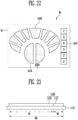
- the GUI for controlling vehicle may include a deceleration control object and an acceleration control object for adjusting a velocity of the vehicle; a plurality of steering control objects for controlling a steering direction of the vehicle; and a plurality of gear control objects for controlling a gear of the vehicle.
- acceleration control object may be disposed at a right side of the deceleration control object.
- the steering control objects may be disposed to surround the deceleration control object and the acceleration control object.
- the display device may enter the manual driving mode in response to a mode change signal transmitted from the vehicle.
- the display device may further include a sound outputter that generates a warning sound when entering the manual driving mode.
- the image display area may further include a second area, and the display may display images surrounding the vehicle on the second area, in the manual driving mode.
- the touch sensor may include a deceleration touch sensor for sensing a touch being input into the deceleration control object; an acceleration touch sensor for sensing a touch being input into the acceleration control object; a steering touch sensor for sensing a touch being input into the steering control objects; and a gear touch sensor for sensing a touch being input into the gear control object.
- the deceleration touch sensor and the acceleration touch sensor may be force sensors capable of sensing the force of the touch.
- the steering touch sensor and the gear touch sensor may be capacitive touch sensors.
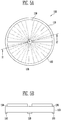
- FIG. 1 is a view illustrating a touch sensor according to an embodiment of the present disclosure
- FIG. 2 is a cross-section taken on line I1-I1' of FIG. 1 .
- a touch sensor 100 may be configured to include a substrate 110, a first sensor 120 and a plurality of second sensors 130.
- the substrate 110 may be formed in a circular shape having a certain radius.
- the substrate 110 may be made of an insulating material such as glass and resin, etc. Further, the substrate 110 may be made of a material having flexibility such that it may be bent or folded, and may have a single-layered structure or a multiple-layered structure.
- the substrate 110 may include at least one of polystyrene, polyvinyl alcohol, polymethyl methacrylate, polyethersulfone, polyacrylate, polyetherimide, polyethylene naphthalate, polyethylene terephthalate, polyphenylene sulfide, polyarylate, polyimide, polycarbonate, triacetate cellulose and cellulose acetate propionate.
- the material constituting the substrate 110 may vary, and thus the substrate 110 may be made of fiber reinforced plastic (FRP) or the like as well.
- FRP fiber reinforced plastic
- the first sensor 120 may be located on one surface of the substrate, for example, in a central area of the substrate 110. More specifically, the first sensor 120 may be located in a center 0 of the substrate 110.
- the first sensor 120 may be a sensor that senses an intensity of a force being applied to the touch sensor 100.
- the plurality of second sensors 130 may be located on a surface opposite to the one surface of the substrate 110 where the first sensor 120 is located. Otherwise, the plurality of second sensors 130 and the first sensor 120 may be located on a same surface of the substrate 110.
- each of the plurality of second sensors 130 may be formed in a fan shape having a certain central angle and a radius, in an isosceles triangle shape having a certain vertical angle, or in a shape similar to the aforementioned fan shape or the isosceles triangle shape having a vertex and a width of the second sensors 130 increases as a distance from the vertex increases.
- the plurality of second sensors 130 may be sectors of a circle such that arcs of the circle form a circular shape having a predetermined space between adjacent sectors. That is, the plurality of second sensors 130 may be arranged such that their vertices surround the central area of the substrate 110, and that their arcs of the circle (or edges) correspond to the circumference of the substrate 110. The vertices of the sectors are formed away from the central area of the circle in which the first sensor 120 is formed.
- the substrate 110 in FIG. 1 is assumed as having a circular shape, there is no limitation thereto, and thus the shape of the substrate 110 may vary.
- Each of the plurality of second sensors 130 is a capacitive touch sensor which senses an amount of change of a capacitance to detect touch positions, and thus contains a conductive material.
- the conductive material constituting the second sensors 130 may contain metal or an alloy thereof.
- the metal include gold (Au), silver (Ag), aluminum (Al), molybdenum (Mo), chrome (Cr), titanium (Ti), nickel (Ni), neodymium (Nd), copper (Cu) and platinum (Pt), etc.
- the conductive material may be made of a transparent conductive material.
- the transparent conductive material include silver nano wire (AgNW), indium tin oxide (ITO), indium zinc oxide (IZO), antimony zinc oxide (AZO), indium tin zinc oxide (ITZO), zinc oxide (ZnO), tin oxide (SnO 2 ), carbon nano tube and graphene, etc.
- FIG. 3 is a block diagram schematically illustrating a touch sensor that includes a sensor controller according to an embodiment of the present disclosure.
- the touch sensor 100 may further include the sensor controller 150.
- the sensor controller 150 may obtain signals sensed by the first sensor 120 and the second sensor 130, and detect a location of a touch applied to the touch sensor 100 and an intensity of the force of the touch, etc.
- the sensor controller 150 may communicate with the first sensor 120 and the plurality of second sensors 130.
- the signal sensed by the first sensor 120 and the signal sensed by the second sensor 130 are processed in the same sensor controller 150, there is no limitation thereto.
- the sensor controller for processing the signal being output from the first sensor 120 and the sensor controller for processing the signal being output from the second sensor 130 may be provided separately from each other.
- FIGs. 4A to 4C are views provided to explain operations of detecting a touch location using the touch sensor illustrated in FIGs. 1 to 3 .
- the touch sensor 100 includes both the first sensor 120 for sensing an intensity of the force of a touch and the second sensor 130 for sensing locations of touch, and thus the sensor controller 150 may compute a touch location and the force of the touch with reference to the signal sensed by the first sensor 120 and the signal sensed by the second sensor 130.
- a coordinate of a touch location is T(r, ⁇ )
- the angle coordinate ( ⁇ ) may be determined depending on the electrode among the plurality of second electrodes 130 from which the touch signal is input.
- the angle coordinate ( ⁇ ) of the touch location may be ⁇ 1
- the angle coordinate of the touch location may be ⁇ 2.
- touches input into the same second sensor 130-1 have the same angle coordinate ⁇ 1.
- a number designated to each of the plurality of second sensors 130 and an angle coordinate value corresponding thereto may be mapped and stored in a memory device.
- the first sensor 120 senses a bending wave that occurred as a finger or the like makes a contact as a touch signal.
- the bending wave always proceeds at a certain velocity regardless of its amplitude (that is, regardless of the intensity of the touch force).
- the distance r the distance the wave travels until the first sensor 120 senses the bending wave occurred by the touch input, may be expressed as in math equation 2 below.
- r since the first sensor 120 is located in the center 0 of the substrate 110, r may be the distance coordinate of the touch location.
- the velocity of the wave v may differ depending on the type of the substrate.
- the first sensor 120 is not disposed in plural locations on the substrate 110, but instead located only in the center of the substrate 110, intensity of the wave generated by the touch input decreases as the distance r increases.
- the decreased amount of wave must be compensated depending on the distance r.
- a and b may differ depending on the type of the medium, that is, the substrate.
- the distance r between the touch input location and the first sensor 120 may a value computed by the aforementioned [math equation 1] and [math equation 2].
- FIG. 5A is a view illustrating a touch sensor that includes a buffer member according to an embodiment of the present disclosure
- FIG. 5B is a view illustrating a cross-section taken on line I2-I2' of FIG. 5A .
- the touch sensor 100 may further include the buffer member 160.
- the buffer member 160 may be provided on the substrate 110 on the same surface as the first sensor 120 is provided. Further, the buffer member 160 may be spaced apart from the first sensor 120 and surrounds the first sensor 120. For example, the buffer member 160 may be formed along an circumference of the one surface of the substrate 110.
- the buffer member 160 may maintain an uniform height of the second sensor 130 and alleviate external impact, thereby performing a function of protecting the first sensor 120.
- the buffer member 160 may have elasticity.
- the buffer member 160 may have elasticity such that it may be transformed by a force from outside and be restored back to its original state once the force is removed.
- a height of the buffer member 160 may be the same or greater than the height of the first sensor 120 so as to protect the first sensor 120 from external force.
- the buffer member 160 may be provided as a porous polymer so that it has elasticity.
- the buffer member 160 may be a foam such as sponge.
- the buffer member 160 may include thermoplastic elastomer, polystyrene, polyolefin, polyurethane thermoplastic elastomers, polyamides, synthetic rubbers, polydimethylsiloxane, polybutadiene, polyisobutylene, poly(styrene-butadienestyrene), polyurethanes, polychloroprene, polyethylene, or silicone, or a combination thereof, but there is no limitation thereto.
- thermoplastic elastomer polystyrene, polyolefin, polyurethane thermoplastic elastomers, polyamides, synthetic rubbers, polydimethylsiloxane, polybutadiene, polyisobutylene, poly(styrene-butadienestyrene), polyurethanes, polychloroprene, polyethylene, or silicone, or a combination thereof, but there is no limitation thereto.
- the buffer member 160 has a circular band shape formed along an entirety of the circumference of the substrate 110, but there is no limitation thereto. That is, the buffer member 160 may be provided in only at least a portion of the circumference of the substrate 110 as long as it can compensate for the difference in height of the second sensor 130 generated as the first sensor 120 is arranged on a lower portion of the substrate 110 and support the substrate 110.
- FIG. 6 is a view illustrating a touch-sensor-integrated display device that includes a touch sensor according to an embodiment of the present disclosure.
- the touch-sensor-integrated display device includes a bracket 170, a display panel 111 accommodated inside the bracket 170, the first sensor 120, the buffer member 160 and a window 180.
- FIG. 6 exemplifies a touch-sensor-integrated display device where a plurality of second sensors 130 are integrated into the display panel 111, and the first sensor 120 is disposed on the lower portion of the display panel 111.
- the location of the sensor may vary of course.
- the sensors 120, 130 may be realized to have a separate substrate 110 as the medium, or as illustrated in FIG. 6 , the second sensor 130 may be integrated into the display panel 111.
- the second sensors 130 are integrated into the window 180.
- the second sensors 130 may be formed on a lower surface of the window 180.
- the location of the first and second sensor 120, 130 and the element being integrated with the sensors may vary.
- the display device may further include a polarizing plate and adhesive, etc.
- FIG. 7 is a view illustrating a touch sensor according to another embodiment of the present disclosure.
- the touch sensor 100a may include a plurality of first sensors 123, 125.
- the plurality of first sensors 123, 125 may be disposed in the central area of the substrate 110, and the plurality of second sensors 130 may be arranged to surround the central area.
- the center of the first sensor 120 is arranged to correspond to the center 0 of the substrate 110.
- At least one of the plurality of first sensors 123, 125 may be spaced apart from the center 0 of the substrate 110 by a certain distance.
- T1, T2 may be input simultaneously into the touch sensor 100a, and the multiple touches T1, T2 may be input to locations having different angle coordinates but a same distance coordinate r1.
- the first sensor 120 senses the waves simultaneously.
- the first sensor 120 may not be able to sense the waves as signals generated by different touches but as one signal, and thus the first sensor 120 may not compute the exact location of the touch input.
- At least one of the plurality of first sensors 123, 125 is provided in a location not corresponding to the center 0 of the substrate.
- the first sensors 123, 125 may sense the touch input at different time points.
- FIG. 7 exemplifies the touch sensor 100a according to the other embodiment where two first sensors 123, 125 are arranged, but there is no limitation thereto. That is, the number of the first sensors 123, 125 may vary.
- FIG. 8 is a view illustrating a touch sensor according to anther embodiment of the present disclosure
- FIG. 9 is a view illustrating a cross-section of the touch sensor illustrated in FIG. 8 .
- the substrate 110 of the touch sensor is a circular shape.
- the substrate 113 of the touch sensor according to the other embodiment of the present disclosure may have a dome shape as illustrated in FIG. 8 , and therefore, the cross-section of the substrate 113 may have an arch shape as illustrated in FIG. 9 .
- the first sensor 120 may be disposed inside the dome-shaped substrate 113. More specifically, assuming the point with the highest level in the substrate 113 is the center of the substrate 113, the first sensor 120 may be provided in a location corresponding to the center.
- the plurality of second sensors 130 may be disposed on an outer surface of the substrate 113, and may be arranged to surround the central area of the substrate 113 on which the first sensor 120 is provided.
- each of the plurality of second sensors 130 may have a shape where a width of the second sensors 130 increases as a distance from the first sensor 120 increases.
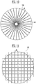
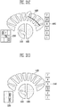
- FIGs. 10 and 11 are views provided to compare and explain the number the sensors provided on a circular substrate in the case where an embodiment of the present disclosure is applied and the number of sensors provided on a circular substrate in the case where conventional method is applied.
- FIG. 10 is a view exemplifying the number of sensors provided on the circular substrate in the case where an embodiment of the present disclosure is applied.
- the second sensor 130 arranged on the substrate has a fan shape having an arc length d1 of 3.925mm.
- thirty-two second sensors 130 may be arranged on the substrate.
- a line for outputting and transmitting a sensed signal to the sensor controller is connected, and since the number of the second sensors 130 in FIG. 10 is thirty two, the number of lines necessary is also thirty two.
- the second sensors 130 are arranged in a circular form, no connection line in the activation area is required.
- FIG. 11 is a view exemplifying the number of sensors provided on a circular substrate in the case where prior art is applied.
- each side of the sensor 137 of the prior art is 4mm, that is, similar to the arc length d1 of the second sensor 130 illustrated in FIG. 10
- each sensor 137 in order to realize an activation area having a radius of 20mm, eighty eight sensors 137 are needed, and therefore, the number of lines needed to be connected to each sensor 137 is eighty eight as well.
- the lines are provided within the activation area, and thus the lines have a lower signal to noise ratio (SNR) compared to the lines according to the present disclosure, and further, since the sensor 137 is provided in areas other than the activation area, dead space, that is unnecessary space, increases.
- SNR signal to noise ratio
- FIG. 12 is a view provided to explain the effect of reducing the number of lines according to an embodiment of the present disclosure.
- FIG. 12 exemplifies that the sensors are arranged on a circular substrate having a radius of R. Further, explanation will be made based on an assumption that the length of the edge of the second sensor (or the length of the arc in the case the second sensor has a fan shape) according to an embodiment of the present disclosure and the width of the self-capacitive touch sensor according to prior art are both 4mm. That is, d1 and d2 illustrated in FIG. 10 and FIG. 11 are both 4mm.
- the number of sensors being provided on the circular substrate is reduced by 8/R compared to the number of self-capacitive type touch sensors that would be provided according to prior art.
- the number of lines necessary for the touch sensor corresponds to the number of sensors provided on the substrate as aforementioned, according to the present disclosure, there is an effect of reducing the number of lines necessary for the touch sensor by as much as 8/R as well compared to prior art.
- the number of lines is reduced to 1/2 compared to that of prior art, and in the case where the radius is 32mm, the number of lines is reduced to 1/4 compared to that of prior art. That is, as illustrated in FIG. 12 , the greater the radius, the greater the effect of reducing the number of lines.
- the prior art touch sensor may be a mutual-capacitive touch sensor instead.
- the mutual-capacitive touch sensor uses a driving sensor and a sensing sensor, both a layer for positioning the driving sensor and a layer for positioning the sensing sensor must be provided.
- shapes and arrangement of the sensors may be configured to correspond to those of the circular substrate, thereby reducing dead space as well.
- the width of the second sensor disposed on the substrate is narrower when it is closer to the center of the substrate, it is possible to realize a higher touch resolution when it is closer to the center of the substrate.
- FIG. 13 is a flowchart provided to explain a method for sensing a touch according to an embodiment of the present disclosure.
- the second sensor senses the touch (S110).
- an angle coordinate of the touch is computed (S120).
- the method for computing the angle coordinate using the second sensor is the same as that mentioned above with reference to FIGs. 4A to 4C , and thus further explanation will be omitted.
- the first sensor senses the touch (S130). When a touch is input on the touch sensor, it takes time for the wave generated by the touch to reach the first sensor located in the center of the substrate, and thus the first sensor may sense the touch later than the second sensor.
- a distance coordinate of the touch is computed using the wave velocity in the substrate and using the aforementioned [math equation 1] and [math equation 2] (S150).
- a final coordinate of the touch is obtained by combining the computed angle coordinate and the distance coordinate (S160).
- an intensity of the force of the touch input is computed (S170).
- the force intensity may be compensated by as much as it decreased using the distance coordinate computed above and [math equation 3].
- FIG. 14 is a view illustrating a first sensor according to an embodiment of the present disclosure.
- the first sensor is provided to perform the function of sensing the force being input into the substrate and the intensity of the force as mentioned above.
- the first sensor according to the embodiment of the present disclosure may be a variable resistance element.
- variable resistance element is an element of which the electrical characteristics change according to an amount of deformation. Its resistance may change in response to the force (or strength) being applied from outside.
- the greater the force being provided to the variable resistance element the smaller the resistance of the variable resistance element may become. Or to the contrary, the greater the force being provided to the variable resistance element, the greater the resistance of the variable resistance element may become.
- variable resistance element may contain a material of which the resistance changes according to force applied to it.
- the variable resistance element may contain materials called a force sensitive material or a force sensitive resistor, etc.
- the variable resistance element may contain at least one of piezo-electric materials such as lead zirconate titanate (PZT) and polyvinylidene fluoride (PVDF) or the like, carbon powder, quantum tunneling composite (QTC), silicone, carbon nano tube and graphene, etc.
- PZT lead zirconate titanate
- PVDF polyvinylidene fluoride
- QTC quantum tunneling composite
- variable resistance element may contain nano particles.
- the nano particles may be provided as nano tubes, nano columns, nano loads, nano pores or nano wires, etc.
- the nano particles may be particles containing carbon, graphite, metalloid, metal, a conductive oxide of metalloid or metal, or a conductive nitride of metalloid or metal; or particles of core shell structures of insulating beads coated with the particles; or a combination thereof.
- the metalloid may contain any one of antimony(Sb), germanium(Ge), arsenic(As), and an alloy thereof.
- the metal may contain zinc(Zn), aluminum(Al), scandium(Sc), chrome(Cr), manganese(Mn), iron(Fe), cobalt(Co), nickel(Ni), copper(Cu), indium(In), tin(Sn), yttrium(Y), zirconium(Zr), niobium(Nb), molybdenum(Mo), ruthenium(Ru), rhodium(Rh), palladium(Pd), gold(Au), silver(Ag), platinum(Pt), strontium(Sr), tungsten(W), cadmium(Cd), tantalum(Ta), titanium(Ti) or an alloy thereof.
- the conductive oxide may contain indium-tin-oxide (ITO), indium-zinc-oxide(IZO), zinc oxide doped with aluminum (AZO), gallium-indium-zinc-oxide (GIZO), zinc oxide (ZnO), or a mixed compound thereof.
- ITO indium-tin-oxide
- IZO indium-zinc-oxide
- AZO aluminum
- GZO gallium-indium-zinc-oxide
- ZnO zinc oxide
- the nano particle may be at least one of carbon nano tube, graphene and silver nano wire, but there is no limitation thereto.
- variable resistance element is not limited to that illustrated in FIG. 14 , and may thus vary.
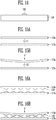
- FIGs. 15A and 15B are views provided to explain a first sensor and a method for operating the same according to another embodiment of the present disclosure.
- the first sensor may include a first conductor 115a and a second conductor 117a.
- the first conductor 115a and the second conductor 117a may be disposed to be spaced apart from each other.
- first conductor 115a there may be an additional element disposed between the first conductor 115a and the second conductor 117a.
- the first conductor 115a and the second conductor 117a contain a conductive material.
- the conductive material may be metal or an alloy of metal.
- the metal include gold (Au), silver (Ag), aluminum (Al), molybdenum (Mo), chrome (Cr), titanium (Ti), nickel (Ni), neodymium (Nd), copper (Cu) and platinum (Pt), etc.
- the first conductor 115a and the second conductor 117a may be made of a transparent conductive material.
- the transparent conductive material include silver nano wire (AgNW), indium tin oxide (ITO), indium zinc oxide (IZO), antimony zinc oxide (AZO), indium tin zinc oxide (ITZO), zinc oxide (ZnO), tin oxide (SnO 2 ), carbon nano tube and graphene, etc.
- the first conductor 115a and the second conductor 117a may be made of a single layer or multiple layers.
- the first conductor 115a and the second conductor 117a may include multiple layers where two or more of the aforementioned materials are laminated.
- first conductor 115a and the second conductor 117a are illustrated to have plate shapes in the drawings, there is no limitation thereto, and thus their shapes may vary.
- the second conductor 117a may be made of a same material as or a different material from the first conductor 115a.
- FIG. 15A illustrates a state where a force F is not applied to the first sensor
- FIG. 15B illustrates a state where a force F is applied to the first sensor.
- a first capacitance C1 is formed between the first conductor 115a and the second conductor 117a.
- the distance between the first conductor 115a and the second conductor 117a is changed, and accordingly, the capacitance of the first conductor 115a and the second conductor 117a may have different value.
- the first capacitance C1 may change to a second capacitance C2 by the force F applied.
- FIGs. 16A and 16B are views provided to explain a first sensor and a method for operating the same according to another embodiment of the present disclosure.
- the first sensor according to the present disclosure may include a first substrate 115b and a second substrate 117b.
- the first substrate 115b and the second substrate 117b may be disposed to be spaced apart from each other.
- a plurality of projections 119 may be formed.
- the first substrate 115b and the second substrate 117b may be arranged such that the projections 119 formed on the first substrate 115b and the projections 119 formed on the second substrate 117b face each other. Further, each of the projections 119 formed on the first substrate 115b may be provided in a location corresponding to each of the projections 119 formed on the second substrate 117b.
- the projections 119 contain a conductive material.
- the conductive material forming the projections 119 may contain metal or an alloy of metal. Examples of the metal or the alloy of metal that may be used herein are the same as aforementioned material, and thus further explanation will be omitted.
- the projection 119 is illustrated in a shape as if an elliptical portion is removed, there is no limitation thereto, and thus the shape of the projection 119 may vary.
- FIG. 16A illustrates a state where a force F is not applied to the first sensor
- FIG. 16B illustrates a state where a force F is applied to the first sensor.
- the projections 119 formed on the first substrate 115b and the projections 119 formed on the second substrate 117b are spaced apart from each other.
- the distance between the first substrate 115b and the second substrate 117b changes, and accordingly, a portion of the projections 119 formed on the first substrate 115b and the projections 119 formed on the second substrate 117b contact each other.
- the greater the intensity of the force F the greater the surface area of contact between the projections formed on the first substrate 115b and the projections formed on the second substrate 117b. That is, from the surface area of contact between the projections 119, it is possible to sense the force F applied to the first sensor and compute the intensity of the force F.
- the first sensor according to an embodiment of the present disclosure may be one of the sensors mentioned above with reference to FIGs. 14 to 16B , but there is no limitation thereto. That is, two or more of the aforementioned sensors may be combined and used as the first sensor.
- An autonomous driving vehicle usually refers to a vehicle that navigates to a destination by recognizing the navigating environment by itself without any manipulation by a driver. Recently, autonomous driving technology is gathering much attention due to expectations that it may reduce a considerable amount of traffic accidents caused by humans' carelessness.
- the passenger may not be able to recognize the navigating situation of the vehicle, or he/she may have difficulties in controlling the vehicle accordingly.
- FIG. 17 is a view illustrating a vehicle control system that uses a display device according to an embodiment of the present disclosure.
- the vehicle control system may include a display device 1100 and a vehicle 1200.
- the display device 1100 may not only perform the general function of displaying contents on a screen but also a function of controlling driving of the vehicle 1200 when necessary.
- the user may view various contents such as videos and photos, etc. through the display device 1100.
- the user may control a navigating direction, speed, gear transmission and the like of the vehicle 1200 through the display device 1100.
- the vehicle 1200 is a vehicle capable of autonomous driving, and also manual driving by a user's manipulation.
- the vehicle 1200 may perform the autonomous driving during autonomous driving modes, and perform the manual driving during manual driving modes.
- motions of the vehicle 1200 may be controlled according to a user's command being input into the display device 1100.
- the display device 1100 and the vehicle 1200 may be connected via wireless network. Accordingly, passengers of the vehicle 1200 may easily use the display device 1100 regardless of their location in the vehicle 1200.
- Wi-Fi Wireless-Fidelity
- RFID Radio Frequency Identification
- IrDA Infrared Data Association
- UWB ultra wide band
- ZigBee ZigBee and Near Field Communication
- the display device 1100 may be a portable terminal, for example, a smart phone, a laptop computer, a Personal Digital Assistant (PDA), a Portable Multimedia Player (PMP), a tablet and a wearable device, etc.
- a portable terminal for example, a smart phone, a laptop computer, a Personal Digital Assistant (PDA), a Portable Multimedia Player (PMP), a tablet and a wearable device, etc.
- PDA Personal Digital Assistant
- PMP Portable Multimedia Player
- tablet a wearable device
- the display device 1100 may be stationed at a certain place inside the vehicle 1200.
- the display device 1100 may or may not have flexibility.
- FIG. 18 is a view illustrating a display device according to an embodiment of the present disclosure.
- the display device 1100 may include a display 1110, a touch sensor 1120, a sound outputter 1130, a haptic module 1140, a communicator 1150 and a display controller 1160.
- the display 1110 may display certain images through an image display area.
- the display 1110 may include a plurality of pixels disposed in the image display area.
- the display 1110 may be realized as display panels of various types, for example, an organic light emitting diode display panel, a liquid crystal display panel, a plasma display panel, an electrophoretic display panel and an electro wetting display panel, etc., but without limitation.
- the touch sensor 1120 may detect a user's touch being input into the display device 1100.
- the touch sensor 1120 may form a mutual layered structure or an integrated structure with the display 1110, thereby realizing a touch screen.
- the touch sensor 1120 may be disposed to overlap with at least a portion of the image display area.
- the sound outputter 1130 may provide sounds necessary for operating the display device 1100 to the user.
- the sound outputter 1130 may output sounds when playing videos or music, and generate signal sounds (for example, warning sounds) signaling that certain functions are being performed.
- Such sound outputter 1130 may include a speaker for outputting sound.
- the haptic module 1140 may generate various haptic effects that may be felt by the user, for example, vibration.
- the intensity, pattern and the like of the vibration generated in the haptic module 1140 may be controlled by the user's selection or by setting the display controller 1160.
- the haptic module 1140 may synthesize different vibrations and output the same, or output different vibrations sequentially.
- the haptic module 1140 may provide the user with a haptic effect for signaling that a certain function is being performed.
- the communicator 1150 may be connected to the vehicle 1200 by a wireless network and perform data transmitting/receiving with the vehicle 1200 via the wireless network.
- the display controller 1160 may control the elements of the display device 1100 mentioned above.
- the display controller 1160 may control operations of the display 1110, the touch sensor 1120, the sound outputter 1130 and the haptic module 1140 according to the driving mode of the vehicle 1200.
- FIG. 19 is a view illustrating a vehicle according to an embodiment of the present disclosure.
- the vehicle 1200 may include a steering device 1210, a deceleration device 1220, an acceleration device 1230, a gear device 1240, an image sensor 1250, a distance sensor 1260, a communicator 1270 and a vehicle controller 1280.
- the vehicle controller 1280 may perform autonomous driving of the vehicle 1200 by automatically controlling the driving devices 1210, 1220, 1230, 1240 during the autonomous driving mode.
- the vehicle controller 1280 may automatically control the driving devices 1210, 1220, 1230, 1240 using information sensed through the image sensor 1250 and the distance sensor 1260.
- the image sensor 1250 may be mounted onto the vehicle 1200 and obtain images (for example, front image, rear image and side image, etc.) surrounding the vehicle 1200.
- a plurality of image sensors 1250 may be installed, and may include a camera for photographing the images surrounding the vehicle 1200.
- the distance sensor 1260 may detect an object (for example, vehicles and obstacles, etc.) surrounding the vehicle 1200, and may measure a distance between the vehicle 1200 and the object. That is, the distance sensor 1260 may detect information on objects surrounding the vehicle 1200.
- the distance sensor 1260 may be realized as a Radio Detection And Ranging (RADAR), Light Detection And Ranging (LIDAR), ultrasonic wave sensor, infrared ray sensor and laser sensor, etc., but without limitation.
- RADAR Radio Detection And Ranging
- LIDAR Light Detection And Ranging
- ultrasonic wave sensor infrared ray sensor and laser sensor, etc.
- the vehicle 1200 may enter the manual driving mode.
- the vehicle controller 1280 may transmit a mode change signal Ce to the display device 1100 through the communicator 1150.
- the display device 1100 may receive the mode change signal Ce through the communicator 1150, in which case the display controller 1160 may recognize that the vehicle 1200 entered the manual driving mode.
- the display controller 1160 may provide a graphical user interface GUI for controlling vehicle to the display 1110.
- the user may control driving of the vehicle 1200 through touch inputs to the GUI for controlling vehicle.
- the display controller 1160 may recognize a user's touch input through the touch sensor 1120, and generate a vehicle control signal Ca reflecting the user's touch input.
- the generated vehicle control signal Ca may be transmitted to the vehicle 1200 through the communicator 1150.
- the vehicle controller 1280 may receive a vehicle control signal Ca through the communicator 1270, and the vehicle controller 1280 may control at least one of the steering device 1210, the deceleration device 1220, the acceleration device 1230 and the gear device 1240 in response to the vehicle control signal Ca.
- the vehicle control signal Ca may include a steering control signal for controlling steering of the vehicle 1200, a deceleration and acceleration control signal for controlling the velocity of the vehicle 1200, and a gear control signal for controlling the gear transmission of the vehicle 1200.
- the vehicle controller 1280 may transmit the surrounding image information Cm of the vehicle 1200 obtained through the image sensor 1250 to the display device 1100.
- the display controller 1160 of the display device 1100 may display images surrounding the vehicle 1200 on the image display area of the display 1110 using the surrounding image information Cm transmitted from the vehicle 1200.
- the display controller 1160 may notify the user that the vehicle entered the manual driving mode.
- the display controller 1160 may control the sound outputter 1130 to generate a warning sound notifying that the vehicle entered the manual driving mode. Further, the display controller 1160 may control the haptic module 1140 to generate the haptic effect (for example, vibration) notifying that the vehicle entered the manual driving mode.
- the haptic module 1140 may control the haptic effect (for example, vibration) notifying that the vehicle entered the manual driving mode.
- the warning sound and the haptic effect may be generated simultaneously or sequentially, and one of the warning sound and the haptic effect may be omitted.
- the communicator 1270 of the vehicle 1200 may perform wireless communication through the communicator 1150 of the display device 1100 and a predetermined wireless network.
- FIG. 20 is a view illustrating a display and a display driver according to an embodiment of the present disclosure.
- the display 1110 of the embodiment of the present disclosure may include a plurality of data lines D1 ⁇ Dm, a plurality of scan lines S1 ⁇ Sn and a plurality of pixels P.
- the pixels P may be disposed in the image display area DA of the display 1110, and may be connected to the data lines D1 ⁇ Dm and the scan lines S1 ⁇ Sn.
- each pixel P may be provided with a data signal and a scan signal through the data lines D1 ⁇ Dm and the scan lines S1 ⁇ Sn.
- the display driver 1300 may include a scan driver 1310, a data driver 1320 and a timing controller 1350.
- the scan driver 1310 may supply scan signals to the scan lines S1 ⁇ Sn in response to a scan driver control signal SCS. For example, the scan driver 1310 may supply the scan signals sequentially to the scan lines S1 ⁇ Sn.
- the scan driver 1310 may be electrically connected to the scan lines S1 ⁇ Sn disposed in the display 1110 through a separate element (for example, circuit board).
- the scan driver 1310 may be directly mounted onto the display 1110.
- the data driver 1320 may receive an input of a data driver control signal DCS and image data DATA from the timing controller 1350, and generate a data signal.
- the data driver 1320 may supply the generated data signal to the data lines D1 ⁇ Dm.
- the data driver 1320 may be electrically connected to the data lines D1 ⁇ Dm disposed in the display 1110 through a separate element (for example, circuit board).
- the data driver 1320 may be directly mounted onto the display 1110.
- some of the pixels P connected to the certain scan line may be supplied with the data signal transmitted from the data lines D1 ⁇ Dm, and the some of the pixels P may emit light of a certain brightness corresponding to the supplied data signal.
- the timing controller 1350 may generate control signals for controlling the scan driver 1310 and the data driver 1320.
- control signals may include a scan driver control signal SCS for controlling the scan driver 1310 and a data driver control signal DCS for controlling the data driver 1320.
- SCS scan driver control signal
- DCS data driver control signal
- timing controller 1350 may supply the scan driver control signal SCS to the scan driver 1310 and supply the data driver control signal DCS to the data driver 1320.
- the timing controller 1350 may convert the image data to fit the specifications of the data driver 1320, and supply the converted image data DATA to the data driver 1320.
- the aforementioned display driver 1300 may perform the roles for controlling the display 1110, which may be included in the aforementioned display controller 1160.
- FIGs. 21A and 21B are views illustrating an image display area in a manual driving mode according to an embodiment of the present disclosure.
- the display 1110 may display a GUI for controlling vehicle M1 on at least a portion of the image display area DA.
- the GUI for controlling vehicle M1 may be displayed on the first area A1 included in the image display area DA.
- the display 1110 may display a surrounding image M2 of the vehicle 1200 on another portion (for example, a second area A2) of the image display area DA.
- the surrounding image M2 of the vehicle 1200 may be obtained through the image sensor 1250 installed in the vehicle 1200.
- the passenger may manually control the driving of the vehicle 1200 through the GUI for controlling vehicle M1 while viewing the surrounding image M2 of the vehicle 1200.
- FIG. 21A illustrates a case where the image display area DA is divided into two areas A1, A2, but the division method of the image display area DA may vary, and further, the arrangement structure of the first area A1 and the second area A2 may vary as well.
- the image display area DA may further include a third area A3.
- contents M3 such as videos, photos and the like may be displayed.
- the user may view the contents M3 displayed on the image display area DA.
- the image display area DA may be converted as illustrated in FIG. 21A , or in FIG. 21B .
- the contents M3 that the passenger was viewing may be displayed continuously.
- FIG. 21B it is illustrated that the image display area DA is divided into three areas A1, A2, A3, but the division method of the image display area DA may vary, and further, the arrangement structure of the first area A1, the second area A2 and the third area A3 may vary as well.
- a third area A3 for displaying contents M3 may basically be included. Further, in the image display area DA during the autonomous driving mode, a first area A1 for displaying the GUI for controlling vehicle M1 and/or a second area A2 for displaying the surrounding image M2 of the vehicle 1200 may be included besides the third area A3.
- FIG. 22 is a view illustrating a graphic user interface for controlling vehicle according to an embodiment of the present disclosure.
- the GUI for controlling vehicle M1 may be displayed on the first area A1.
- Such GUI for controlling vehicle M1 may include numerous objects 1410, 1420, 1430, 1440 for controlling driving of the vehicle 1200.
- the GUI for controlling vehicle M1 may include a deceleration control object 1410 and an acceleration control object 1420 for controlling velocity of the vehicle 1200, a plurality of steering control objects 1430 for adjusting a steering direction of the vehicle 1200, and a plurality of gear control objects 1440 for adjusting a gear of the vehicle 1200.
- the deceleration control object 1410 may correspond to a brake of the vehicle
- the acceleration control object 1420 may correspond to the accelerator of the vehicle.
- the steering control objects 1430 may correspond to a steering wheel of the vehicle
- the gear control objects 1440 may correspond to a gear control lever of the vehicle.
- the acceleration control object 1420 may be disposed at a right side of the deceleration control object 1410, and the gear control objects 1440 may be disposed at a right side of the deceleration control object 1410, the acceleration control object 1420 and the steering control objects 1430.
- steering control objects 1430 may be arranged in a shape of surrounding the deceleration control object 1410 and the acceleration control object 1420.
- Each of the gear control objects 1440 may also display a gear stage of a gear.
- each of the gear control objects 1440 may also display the gear stages such as P, R, N, D, 2 and 1, respectively.
- the user may adjust the velocity of the vehicle 1200 by touching the deceleration control object 1410 and the acceleration control object 1420, and may adjust the driving direction of the vehicle 1200 by touching the steering control objects 1430, and adjust the gear stage of the vehicle 1200 by touching the gear control objects 1440.
- FIG. 23 is a view illustrating a display and a touch sensor according to an embodiment of the present disclosure.
- the touch sensor 1120 may be disposed to overlap with the display 1110.
- the coupling method of the display 1110 and the touch sensor 1120 may vary. For example, they may be coupled in an in-cell method or an on-cell method, but without limitation.
- the touch sensor 1120 may include a first touch sensor 1121 for sensing a touch being input into the first area A1.
- the first touch sensor 1121 may be disposed to overlap with the first area A1.
- the user may recognize the GUI for controlling vehicle M1 being disposed on the first area A1, and perform a touch on the GUI for controlling vehicle M1.
- the first touch sensor 1121 may sense a location, a force and the like of the touch.
- the detailed first touch sensor 1121 will be explained later.
- the touch sensor 1120 may include a second touch sensor 1122 for sensing a touch being input into the rest of the area Ar besides the first area A1 of the image display area DA.
- the second touch sensor 1122 may be disposed to overlap with the rest of the area Ar.
- the user may perform a touch regarding the surrounding image M2 of the vehicle 1200 and the contents M3 being displayed on the rest of the area Ar.
- the second touch sensor 1122 may be realized in various methods.
- the second touch sensor 1122 may be realized as a capacitive touch sensor, a resistive touch sensor, an optical touch sensor, or the like, but without limitation.
- FIG. 24 is a view illustrating a first touch sensor according to an embodiment of the present disclosure.
- the first touch sensor 1121 may include a deceleration touch sensor 1510, an acceleration touch sensor 1520, a steering touch sensor 1530, and a gear touch sensor 1540.
- the deceleration touch sensor 1510 may sense a touch being input into the deceleration control object 1410 of the GUI for controlling vehicle M1.
- the deceleration touch sensor 1510 may be realized as a force sensor capable of sensing a force of a touch such that it operates similarly as an actual brake.
- the deceleration control object 1410 may have a shape that is the same as or different from that of the deceleration touch sensor 1510, and the deceleration control object 1410 may be displayed on a location that overlaps with the deceleration touch sensor 1510 in the first area A1.
- the display controller 1160 may detect a force of the input touch, and may transmit a vehicle control signal Ca where the detected force is reflected, to the vehicle controller 1280.
- the vehicle controller 1280 may adjust the deceleration device 1220 with reference to the force information included in the vehicle control signal Ca, and accordingly, the velocity of the vehicle 1200 may be reduced.
- the acceleration touch sensor 1520 may sense a touch being input into the acceleration control object 1420 of the GUI for controlling vehicle M1.
- the acceleration touch sensor 1520 may be realized as a force sensor capable of sensing a force of a touch such that it operates similarly as an actual accelerator.
- the acceleration control object 1420 may have a shape that is the same as or similar to the acceleration touch sensor 1520, and may be displayed on a location that overlaps with the acceleration touch sensor 1520 of the first area A1.
- the acceleration touch sensor 1520 may be disposed at a right side of the deceleration touch sensor 1510, that is the same as the arrangement structure of the actual brake and the accelerator.
- the display controller 1150 may detect a force of the touch input, and further, the display controller 1150 may transmit the vehicle control signal Ca where the detected force is reflected, to the vehicle controller 1280.
- the vehicle controller 1280 may adjust the acceleration device 1230 with reference to the force information included in the vehicle control signal Ca, and accordingly, the velocity of the vehicle 1200 may be increased.
- the steering touch sensor 1530 may sense the touch being input into the steering control objects 1430 of the GUI for controlling vehicle M1.
- the steering touch sensor 1530 may be realized as a self-capacitive touch sensor.
- the steering touch sensor 1530 may include a plurality of electrodes 1531, and the display controller 1160 may detect the location of the touch based on the amount of change of the self-capacitance of the electrodes 1531.
- the steering control objects 1430 may have a shape that is the same as or similar to the electrodes 1531 of the steering touch sensor 1530, and may be displayed on a location overlapping with each electrode 1531 in the first area A1.
- the electrodes 1531 of the steering touch sensor 1530 may be arranged such that they surround the deceleration touch sensor 1510 and the acceleration touch sensor 1520.
- the shape and surface area of the electrodes 1531 may be set to be the same or to be different depending on their locations.
- the electrodes 1531 may be arranged in a bilaterally symmetrical form.
- the display controller 1160 may detect the location of the input touch, and may transmit the vehicle control signal Ca where the detected touch location is reflected, to the vehicle controller 1280.
- the vehicle controller 1280 may adjust the steering device 1210 with reference to the touch location information included in the vehicle control signal Ca, and accordingly, the driving direction of the vehicle 1200 may be changed.
- the display controller 1160 may detect the direction of the touch input, and may transmit the vehicle control signal Ca where the detected direction of the touch input is reflected, to the vehicle controller 1280.
- the vehicle controller 1280 may adjust the steering device 1210 with reference to the information on the direction of the touch included in the vehicle control signal Ca, and accordingly, the driving direction of the vehicle 1200 may be changed.
- the electrodes 1531 of the steering touch sensor 1530 may include a conductive material.
- the conductive material may include metal or an alloy thereof.
- the metal include gold (Au), silver (Ag), aluminum (Al), molybdenum (Mo), chrome (Cr), titanium (Ti), nickel (Ni), neodymium (Nd), copper (Cu) and platinum (Pt), etc.
- the electrodes 1531 may be made of a transparent conductive material.
- the transparent conductive material include silver nano wire (AgNW), indium tin oxide (ITO), indium zinc oxide (IZO), antimony zinc oxide (AZO), indium tin zinc oxide (ITZO), zinc oxide (ZnO), tin oxide (SnO 2 ), carbon nano tube and graphene, etc.
- the electrodes 1531 may have a single-layered structure or a multiple-layered structure, for example, a multiple layer where two or more of the aforementioned materials are laminated.
- the gear touch sensor 1540 may sense a touch being input into the gear control objects 1440 of the GUI for controlling vehicle M1.
- the gear touch sensor 1540 may be realized as a self-capacitive sensor.
- the gear touch sensor 1540 may include a plurality of electrodes 1541, and the display controller 1160 may detect a touch location based on an amount of change of the self-capacitance of the electrodes 1541.
- the shape and surface area of the electrodes 1541 may be set to be the same or to be different depending on their locations.
- the shape of the electrodes 1541 may vary, for example, a rectangle, a triangle, a circle and the like.
- the gear control objects 1440 may have shapes that are the same as or similar to the electrodes 1541 of the gear touch sensor 1540, and may be displayed on a location overlapping with each of the electrodes 1541 in the first area A1.
- the gear touch sensor 1540 may be disposed at a rightmost side compared to the deceleration touch sensor 1510, the acceleration touch sensor 1520 and the steering touch sensor 1530, that is the same as the arrangement structure of the actual gear control lever.
- the display controller 1160 may detect a location of the input touch, and accordingly, may recognize the gear stage selected by the user.
- the display controller 1160 may transmit information where the gear stage selected by the user is reflected, to the vehicle controller 1280.
- the vehicle controller 1280 may adjust the gear device 1240 with reference to the information on the gear stage included in the vehicle control signal Ca, and accordingly, the gear stage of the vehicle 1200 may be changed.
- the electrodes 1541 of the gear touch sensor 1540 may be made of a same material as the electrodes 1531 of the steering touch sensor 1530, and may have a same layered structure as the electrodes 1531 of the steering touch sensor 1530.
- FIG. 25 is a view illustrating a first touch sensor according to another embodiment of the present disclosure.
- the steering touch sensor 1530 may be realized as a mutual-capacitive touch sensor.
- the steering touch sensor 1530 may include first electrodes 1531 and second electrodes 1532.
- the first electrodes 1531 and the second electrodes 1532 may be arranged such that they surround the deceleration touch sensor 1510 and the acceleration touch sensor 1520.
- first electrodes 1531 and the second electrodes 1532 may be arranged to mutually intersect each other.
- the second electrodes 1532 may be bent and extent in a direction to intersect the first electrodes 1531.
- mutual-capacitance is formed between the first electrodes 1531 and the second electrodes 1532, and the display controller 1160 may detect a touch location based on an amount of change of the capacitance.
- an insulating film (not illustrated) may be disposed near an area where the first electrodes 1531 and the second electrodes 1532 intersect each other.
- FIGs. 26A, 26B and 26C are views illustrating various examples of shapes of the deceleration touch sensor, the acceleration touch sensor and the steering touch sensor according to an embodiment of the present disclosure.
- the deceleration touch sensor 1510 and the acceleration touch sensor 1520 may have rectangular shapes.
- the actual shape of the deceleration touch sensor 1510 and the acceleration touch sensor 1520 may vary.
- the deceleration touch sensor 1510 and the acceleration touch sensor 1520 may have a semicircular shape (refer to FIG. 24 ), a circular shape, a triangular shape, or the like.
- the electrodes 1531 of the steering touch sensor 1530 may have shapes where the closer it is to the outer side, the greater the width.
- the electrodes 1531 may have fan shapes or shapes similar to fans, but without limitation.
- the shape of the electrodes 1531 may vary.
- the electrodes 1531 of the steering touch sensor 1531 may be arranged such that they generally surround the deceleration touch sensor 1510 and the acceleration touch sensor 1520.
- FIGs. 26A, 26B and 26C are views illustrating examples of the various shapes and arrangement structures of the sensors 1510, 1520, 1530, 1540 of the present disclosure, but without limitation.
- deceleration touch sensor 1510 and the acceleration touch sensor 1520 may have a same structure, and thus, explanation herein will focus on the deceleration touch sensor 1510.
- FIG. 27 is a view illustrating the deceleration touch sensor according to an embodiment of the present disclosure.
- the deceleration touch sensor 1510 may perform a function of a force sensor of sensing a force of a touch as aforementioned.
- the deceleration touch sensor 1510 may include a variable resistance element 1511.
- the variable resistance element 1511 may be disposed on a separate base layer 1512.
- the variable resistance element 1511 is an element of which the electrical characteristics change according to the extent it is deformed. Its resistance may change in response to the force (or strength) being applied from outside. For example, the greater the force being provided to the variable resistance element, the smaller the resistance of the variable resistance element may become. Or to the contrary, the greater the force being provided to the variable resistance element, the greater the resistance of the variable resistance element may become.
- the display controller 1160 may detect a touch force based on an amount of change of the resistance of the variable resistance element 1511.
- the variable resistance element 1511 may include a material of which the resistance changes according to force applied to the variable resistance element 1511.
- the variable resistance element may contain materials called a force sensitive material or a force sensitive resistor, etc.
- the variable resistance element 1511 may contain at least one of a piezo-electric material such as lead zirconate titanate (PZT) and polyvinylidene fluoride (PVDF) or the like, carbon powder, quantum tunneling composite (QTC), silicone, carbon nano tube and graphene, etc.
- a piezo-electric material such as lead zirconate titanate (PZT) and polyvinylidene fluoride (PVDF) or the like
- QTC quantum tunneling composite
- silicone carbon nano tube and graphene, etc.
- variable resistance element 1511 may contain nano particles.
- the nano particles may be provided as nano tubes, nano columns, nano loads, nano pores or nano wires, etc.
- the nano particles may be particles containing carbon, graphite, metalloid, metal, a conductive oxide of metalloid or metal, or a conductive nitride of metalloid or metal; or particles of core shell structures of insulating beads coated with the particles; or a combination thereof.
- the metalloid may contain any one of antimony(Sb), germanium(Ge), arsenic(As), and an alloy thereof.
- the metal may contain zinc(Zn), aluminum(Al), scandium(Sc), chrome(Cr), manganese(Mn), iron(Fe), cobalt(Co), nickel(Ni), copper(Cu), indium(In), tin(Sn), yttrium(Y), zirconium(Zr), niobium(Nb), molybdenum(Mo), ruthenium(Ru), rhodium(Rh), palladium(Pd), gold(Au), silver(Ag), platinum(Pt), strontium(Sr), tungsten(W), cadmium(Cd), tantalum(Ta), titanium(Ti) or an alloy thereof.
- the conductive oxide may contain indium-tin-oxide (ITO), indium-zinc-oxide(IZO), zinc oxide doped with aluminum (AZO), gallium-indium-zinc-oxide (GIZO), zinc oxide, or a mixed compound thereof.
- ITO indium-tin-oxide
- IZO indium-zinc-oxide
- AZO zinc oxide doped with aluminum
- GZO gallium-indium-zinc-oxide
- zinc oxide or a mixed compound thereof.
- the nano particle may be at least one of carbon nano tube, graphene and silver nano wire, but there is no limitation thereto.
- variable resistance element 1511 is not limited to that illustrated in FIG. 27 , and may thus vary.
- FIGs. 28A and 28B are views provided to explain a deceleration touch sensor and a method for operating the same according to another embodiment of the present disclosure.
- the deceleration touch sensor 1510 may include a first conductor 1513 and a second conductor 1514.
- the first conductor 1513 and the second conductor 1514 may be disposed to be spaced apart from each other.
- first conductor 1513 there may be an additional element disposed between the first conductor 1513 and the second conductor 1514.
- the first conductor 1513 and the second conductor 1514 contain a conductive material.
- the conductive material may be metal or an alloy of metal.
- the metal include gold (Au), silver (Ag), aluminum (Al), molybdenum (Mo), chrome (Cr), titanium (Ti), nickel (Ni), neodymium (Nd), copper (Cu) and platinum (Pt), etc.
- the first conductor 1513 and the second conductor 1514 may be made of a transparent conductive material.
- the transparent conductive material include silver nano wire (AgNW), indium tin oxide (ITO), indium zinc oxide (IZO), antimony zinc oxide (AZO), indium tin zinc oxide (ITZO), zinc oxide (ZnO), tin oxide (SnO 2 ), carbon nano tube and graphene, etc.
- the first conductor 1513 and the second conductor 1514 may be made of a single layer or multiple layers.
- the first conductor 1513 and the second conductor 1514 may include multiple layers where two or more of the aforementioned materials are laminated.
- first conductor 1513 and the second conductor 1514 are illustrated in the drawings to have plate shapes, there is no limitation thereto, and thus their shapes may vary.
- the second conductor 1514 may be made of a same material as or a different material from the first conductor 1513.
- FIG. 28A illustrates a state where a force F is not applied to the deceleration touch sensor 1510
- FIG.28B illustrates a state where a force F is applied to the deceleration touch sensor 1510.
- a first capacitance C1 is formed between the first conductor 1513 and the second conductor 1514.
- the distance between the first conductor 1513 and the second conductor 1514 changes, and accordingly, the capacitance formed by the first conductor 1513 and the second conductor 1514 may change.
- the first capacitance C1 may change to a second capacitance C2 by the force F being applied.
- the mutual capacitance of the first conductor 1513 and the second conductor 1514 may vary in response to the force F being applied from outside.
- the display controller 1160 may detect a touch force F based on an amount of change of the mutual-capacitance.
- FIGs. 29A and 29B are views provided to explain a deceleration touch sensor and a method for operating the same according to another embodiment of the present disclosure.
- the deceleration touch sensor 1510 may include a first substrate 1515 and a second substrate 1516.
- the first substrate 1515 and the second substrate 1516 may be disposed to be spaced apart from each other.
- a plurality of projections 1517, 1518 may be formed.
- the first substrate 1515 and the second substrate 1516 may be arranged such that first projections 1517 formed on the first substrate 1515 and second projections 1518 formed on the second substrate 1516 face each other. Further, each of the first projections 1517 may be provided in a location corresponding to each of the second projections 1518.
- the projections 1517, 1518 may contain a conductive material.
- the conductive material forming the projections 1517, 1518 may contain metal or an alloy of metal. Examples of the metal or the alloy of metal that may be used herein are the same as aforementioned, and thus further explanation will be omitted.
- the projections 1517, 1518 are illustrated in shapes as if an elliptical portion is removed, there is no limitation thereto, and thus the shape of the projection 1517, 1518 may vary.
- FIG. 29A illustrates a state where a force F is not applied to the deceleration touch sensor 1510
- FIG. 29B illustrates a state where a force F is applied to the deceleration touch sensor 1510.
- the first projections 1517 and the second projections 1518 are spaced apart from each other.
- the distance between the first substrate 1515 and the second substrate 1516 changes, and accordingly, a portion of the first projections 1517 and the second projections 1518 contact each other.
- FIG 30 is a flowchart illustrating a vehicle control method using a display device according to an embodiment of the present disclosure.
- a vehicle 1200 set to an autonomous driving mode may perform an autonomous driving (refer to S1100).
- a passenger may freely use games and contents using the display device 1100 connected to the vehicle 1200 via wireless network.
- a step of determining whether or not an error occurred in the autonomous driving system of the vehicle 1200 may be performed (S1200).
- the vehicle 1200 may end the autonomous driving and convert to a manual driving (refer to S1300).
- the display device 1100 may generate a warning sound and/or a haptic effect in order to notify the user.
- the autonomous driving mode may continue.
- the display device 1100 may display a GUI for controlling vehicle M1 on at least a portion of the image display area DA (for example, on the first area A1) (refer to S1400).
- a step of manually controlling the vehicle 1200 in response to a user's touch being input into the GUI for controlling vehicle M1 may be performed (S1500).
- the user may manually control the vehicle 1200 through the deceleration control object 1410, the acceleration control object 1420, the steering control objects 1430 and the gear control objects 1440 included in the GUI for controlling vehicle M1.
- FIGs. 31A, 31B , 31C and 31D are views illustrating how the vehicle 1200 is manually navigated by a vehicle control method according to an embodiment of the present disclosure.
- FIG. 31A illustrates the vehicle 1200 making a left turn while reducing its velocity.
- the user may set the gear to D to make the vehicle 1200 go straight.
- the gear control objects 1440 the user may touch the gear control object set to D gear.
- the gear of the vehicle 1200 may be automatically set to D gear. In this case, there is no need for the user to make an additional input to control the gear of the vehicle 1200.
- the user may touch the steering control objects 1430 while already touching the deceleration control object 1410.
- the user may control the velocity and steering of the vehicle 1200 with one hand (for example, the thumb and the index finger).
- the vehicle 1200 may decelerate in response to the intensity of the touch force being input regarding the deceleration control object 1410, and may turn left in response to the direction of the touch being input regarding the steering control objects 1430.
- the user may move the touch input regarding the steering control objects 1430 to the left side in order to make the vehicle 1200 turn left.
- FIG. 31B illustrates the vehicle 1200 making a left turn while increasing its velocity.
- the user may maintain the gear of the vehicle 1200 in D gear, that is the same as in FIG. 31A .
- the user may perform a touch on the steering control objects 1430 while already touching the acceleration control object 1420.
- the vehicle 1200 may accelerate in response to the intensity of the touch force being input regarding the acceleration control object 1420, and may turn left in response to the direction of the touch being input regarding the steering control objects 1430.
- the user may move the touch input regarding the steering control objects 1430 to the left for the vehicle 1200 to make a left turn.
- FIG. 31C illustrates the vehicle 1200 performing a rear-parking operation.
- the user may set the gear to R gear to make a backward motion.
- the gear control objects 1440 the user may touch the gear control object set to R gear.
- the user may touch the steering control objects 1430 while already touching the deceleration control object 1410.
- FIG. 31D illustrates how the vehicle 1200 decelerates while going straight.
- the user may maintain the gear of the vehicle 1200 in D gear, that is the same as in FIG. 31A .
- the user may perform a touch on the deceleration control object 1410.
- FIGs. 31A to 31D exemplify only some of vehicle drivings, and thus various types of driving controls may be made according to user's input.
- Example embodiments have been disclosed herein, and although specific terms are employed, they are used and are to be interpreted in a generic and descriptive sense only and not for purpose of limitation. In some instances, as would be apparent to one of ordinary skill in the art as of the filing of the present application, features, characteristics, and/or elements described in connection with a particular embodiment may be used singly or in combination with features, characteristics, and/or elements described in connection with other embodiments unless otherwise specifically indicated.
Landscapes
- Engineering & Computer Science (AREA)
- Transportation (AREA)
- Mechanical Engineering (AREA)
- Theoretical Computer Science (AREA)
- General Engineering & Computer Science (AREA)
- Chemical & Material Sciences (AREA)
- Combustion & Propulsion (AREA)
- Human Computer Interaction (AREA)
- Physics & Mathematics (AREA)
- General Physics & Mathematics (AREA)
- Automation & Control Theory (AREA)
- Mathematical Physics (AREA)
- Aviation & Aerospace Engineering (AREA)
- Radar, Positioning & Navigation (AREA)
- Remote Sensing (AREA)
- Computing Systems (AREA)
- Electromagnetism (AREA)
- Position Input By Displaying (AREA)
- Control Of Driving Devices And Active Controlling Of Vehicle (AREA)
- Business, Economics & Management (AREA)
- Health & Medical Sciences (AREA)
- Artificial Intelligence (AREA)
- Evolutionary Computation (AREA)
- Game Theory and Decision Science (AREA)
- Medical Informatics (AREA)
- User Interface Of Digital Computer (AREA)
Abstract
Description
- Various embodiments of the present disclosure relate to a touch sensor and a method for sensing a touch using the same.
- As the interest in information displays grows and demand to use portable information media increases, studies and commercialization are being concentrated on display devices.
- Recent display devices are being equipped with image display functions and touch sensors for receiving inputs of users' touches. Accordingly, users have become able to use display devices more conveniently through touch sensors.
- Further, recent efforts have been made to provide various functions to users using not only touch locations but also using forces occurred by users' touches.
- A purpose of the present disclosure is to provide a touch sensor structure optimized to a circular form.
- Another purpose of the present disclosure is to provide a method for complexly identifying a touched point and an intensity of the touch using the touch sensor optimized to the circular form.
- According to an embodiment of the present disclosure, there is provided a touch sensor including a substrate; and a first sensor and a plurality of second sensors provided on the substrate, and configured to sense a location and a force of a touch, wherein the first sensor is disposed in a central area of one surface of the substrate, the plurality of second sensors are arranged to surround the first sensor, and a width of the plurality of second sensors increases as a distance from the central area increases.
- Further, the plurality of second sensors may be provided on another surface facing the one surface of the substrate.
- Further, the first sensor may be a force sensing sensor, and the plurality of second sensors may be capacitive sensors.
- Further, the substrate may be a flat plane substrate having a circular shape.
- Further, the touch sensor may further include a sensor controller that computes the location and intensity of force of the touch using a sensing signal obtained from the first sensor and the plurality of second sensors.
- Further, the sensor controller may compute the location of the touch with reference to a polar coordinate.
- Further, the sensor controller may compute an angle coordinate of the touch with reference to the sensing signal obtained from the plurality of second sensors.
- Further, the sensor controller may compute a distance coordinate with reference to a time difference between the touch is sensed by the first sensor and the touch is sensed by the second sensor.
- Further, the sensor controller may compute the intensity of the force sensed by the first sensor.
- Further, the sensor controller may compensate for the sensed intensity of the force with reference to the distance coordinate of the touch.
- According to another embodiment of the present disclosure, there is provided a display device for controlling a vehicle connected via a network, the device including a display that displays an image through an image display area that includes a first area; and a touch sensor for detecting a touch being input into the first area, wherein the display displays a user interface (GUI) for controlling the vehicle on the first area, in a manual driving mode.
- Further, the GUI for controlling vehicle may include a deceleration control object and an acceleration control object for adjusting a velocity of the vehicle; a plurality of steering control objects for controlling a steering direction of the vehicle; and a plurality of gear control objects for controlling a gear of the vehicle.
- Further, the acceleration control object may be disposed at a right side of the deceleration control object.
- Further, the steering control objects may be disposed to surround the deceleration control object and the acceleration control object.
- Further, the display device may enter the manual driving mode in response to a mode change signal transmitted from the vehicle.
- Further, the display device may further include a sound outputter that generates a warning sound when entering the manual driving mode.
- Further, the image display area may further include a second area, and the display may display images surrounding the vehicle on the second area, in the manual driving mode.
- Further, the touch sensor may include a deceleration touch sensor for sensing a touch being input into the deceleration control object; an acceleration touch sensor for sensing a touch being input into the acceleration control object; a steering touch sensor for sensing a touch being input into the steering control objects; and a gear touch sensor for sensing a touch being input into the gear control object.
- Further, the deceleration touch sensor and the acceleration touch sensor may be force sensors capable of sensing the force of the touch.
- Further, the steering touch sensor and the gear touch sensor may be capacitive touch sensors.
- According to an embodiment of the present disclosure, it is possible to provide a touch sensor optimized to a circular form.
- Further, according to an embodiment of the present disclosure, it is possible to complexly identify a touched point and an intensity of the touch using a sensor arranged in a simple structure.
- Further, according to an embodiment of the present disclosure, it is possible to realize a touch sensor with only a small number of sensors and wires.
- Further, according to an embodiment of the present disclosure, it is possible to reduce dead space.
- Further, according to an embodiment of the present disclosure, it is possible to provide a high touch resolution.
- Example embodiments are described hereinafter with reference to the accompanying drawings. However, the present system and method may be embodied in different forms and are not limited to the embodiments set forth herein. Rather, these embodiments are provided as examples to facilitate the understanding of the present teachings by those of ordinary skill in the art.
- In the drawings, the dimensions of the figures may be exaggerated for clarity of illustration. When an element is referred to as being "between" two elements, the element may be the only element present between the two elements, or one or more intervening elements may also be present. Like reference numerals refer to like elements throughout.
-
FIG. 1 is a view illustrating a touch sensor according to an embodiment of the present disclosure; -
FIG. 2 is a view illustrating a cross-section taken on line I1-I1' ofFIG. 1 ; -
FIG. 3 is a block diagram schematically illustrating a touch sensor that includes a sensor controller according to an embodiment of the present disclosure; -
FIGs. 4A ,4B and 4C are views provided to explain operations for detecting a touch location using the touch sensor illustrated inFIGs. 1 and 2 ; -
FIG. 5A is a view illustrating a touch sensor that includes a buffer member according to an embodiment of the present disclosure; -
FIG. 5B is a view illustrating a cross-section taken on line I2-I2' ofFIG. 5A ; -
FIG. 6 is a view illustrating a touch-sensor-integrated type display device that includes a touch sensor according to an embodiment of the present disclosure; -
FIG. 7 is a view illustrating a touch sensor according to another embodiment of the present disclosure; -
FIGs. 8 and 9 are views illustrating a touch sensor according to another embodiment of the present disclosure; -
FIGs. 10 and 11 are views provided to compare the number of sensors provided in a circular-type substrate in a case where an embodiment of the present disclosure is applied, and the number of sensors provided in a circular-type substrate in a case where prior art is applied; -
FIG. 12 is a view provided to explain the effect of reducing the number of lines according to an embodiment of the present disclosure; -
FIG. 13 is a flowchart provided to explain a method for sensing a touch according to an embodiment of the present disclosure; -
FIG. 14 is a view illustrating a first sensor according to an embodiment of the present disclosure; -
FIGs. 15A and 15B are views provided to explain a first sensor and an operation method thereof according to another embodiment of the present disclosure; -
FIGs. 16A and 16B are views provided to explain a first sensor and an operation method thereof according to another embodiment of the present disclosure; -
FIG. 17 is a view illustrating a vehicle control system that uses a display device according to an embodiment of the present disclosure; -
FIG. 18 is a view illustrating a display device according to an embodiment of the present disclosure; -
FIG. 19 is a view illustrating a vehicle according to an embodiment of the present disclosure; -
FIG. 20 is a display and a display driver according to an embodiment of the present disclosure; -
FIGs. 21A and 21B are views illustrating an image display area in a manual driving mode according to an embodiment of the present disclosure; -
FIG. 22 is a view illustrating a graphic user interface for controlling vehicle according to an embodiment of the present disclosure; -
FIG. 23 is a view illustrating a display and a touch sensor according to an embodiment of the present disclosure; -
FIG. 24 is a view illustrating a first touch sensor according to an embodiment of the present disclosure; -
FIG. 25 is a view illustrating a first touch sensor according to another embodiment of the present disclosure; -
FIGs. 26A, 26B and26C are views illustrating examples of various forms of a deceleration touch sensor, an acceleration touch sensor and a steering touch sensor according to an embodiment of the present disclosure; -
FIG. 27 is a view illustrating a deceleration touch sensor according to an embodiment of the present disclosure; -
FIGs. 28A and 28B are views provided to explain a deceleration touch sensor and an operation method thereof according to another embodiment of the present disclosure; -
FIGs. 29A and 29B are views provided to explain a deceleration touch sensor and an operation method thereof according to another embodiment of the present disclosure; -
FIG. 30 is a flowchart illustrating a vehicle control method using a display device according to an embodiment of the present disclosure; and -
FIGs. 31A, 31B ,31C and 31D are views illustrating how a vehicle is being manually navigated by a vehicle control method according to an embodiment of the present disclosure. - Although only certain exemplary embodiments of the present system and method are shown and described herein for purposes of illustration, those of ordinary skill in the art would understand that the described embodiments may be modified in various different ways without departing from the spirit or scope of the present system and method. Accordingly, the drawings and description are illustrative in nature and not restrictive. When an element is referred to as being "connected to" another element, it may be directly connected to the other element, or it may be indirectly connected to the other element through one or more intervening elements. Hereinafter, like reference numerals refer to like elements. In the drawings, the thickness or size of layers may be exaggerated for clarity and not necessarily drawn to scale. In the drawings, lengths and sizes of layers and regions may be exaggerated for clarity. Like reference numerals in the drawings denote like elements.
- Hereinafter, a touch sensor and a method for sensing a touch using the same according to an embodiment of the present disclosure will be explained with reference to the drawings.
-
FIG. 1 is a view illustrating a touch sensor according to an embodiment of the present disclosure, andFIG. 2 is a cross-section taken on line I1-I1' ofFIG. 1 . - Referring to
FIGs. 1 and 2 , atouch sensor 100 according to an embodiment of the present disclosure may be configured to include asubstrate 110, afirst sensor 120 and a plurality ofsecond sensors 130. - The
substrate 110 may be formed in a circular shape having a certain radius. - The
substrate 110 may be made of an insulating material such as glass and resin, etc. Further, thesubstrate 110 may be made of a material having flexibility such that it may be bent or folded, and may have a single-layered structure or a multiple-layered structure. - For example, the
substrate 110 may include at least one of polystyrene, polyvinyl alcohol, polymethyl methacrylate, polyethersulfone, polyacrylate, polyetherimide, polyethylene naphthalate, polyethylene terephthalate, polyphenylene sulfide, polyarylate, polyimide, polycarbonate, triacetate cellulose and cellulose acetate propionate. However, the material constituting thesubstrate 110 may vary, and thus thesubstrate 110 may be made of fiber reinforced plastic (FRP) or the like as well. - The
first sensor 120 may be located on one surface of the substrate, for example, in a central area of thesubstrate 110. More specifically, thefirst sensor 120 may be located in acenter 0 of thesubstrate 110. - The
first sensor 120 may be a sensor that senses an intensity of a force being applied to thetouch sensor 100. - Types and operation methods of the
first sensor 120 will be explained in detail hereinafter with reference toFIGs. 14 to 16B . - The plurality of
second sensors 130 may be located on a surface opposite to the one surface of thesubstrate 110 where thefirst sensor 120 is located. Otherwise, the plurality ofsecond sensors 130 and thefirst sensor 120 may be located on a same surface of thesubstrate 110. - As illustrated in
FIG. 1 , each of the plurality ofsecond sensors 130 may be formed in a fan shape having a certain central angle and a radius, in an isosceles triangle shape having a certain vertical angle, or in a shape similar to the aforementioned fan shape or the isosceles triangle shape having a vertex and a width of thesecond sensors 130 increases as a distance from the vertex increases. - Further, the plurality of
second sensors 130 may be sectors of a circle such that arcs of the circle form a circular shape having a predetermined space between adjacent sectors. That is, the plurality ofsecond sensors 130 may be arranged such that their vertices surround the central area of thesubstrate 110, and that their arcs of the circle (or edges) correspond to the circumference of thesubstrate 110. The vertices of the sectors are formed away from the central area of the circle in which thefirst sensor 120 is formed. - Meanwhile, although the
substrate 110 inFIG. 1 is assumed as having a circular shape, there is no limitation thereto, and thus the shape of thesubstrate 110 may vary. - Each of the plurality of
second sensors 130 is a capacitive touch sensor which senses an amount of change of a capacitance to detect touch positions, and thus contains a conductive material. For example, the conductive material constituting thesecond sensors 130 may contain metal or an alloy thereof. Examples of the metal include gold (Au), silver (Ag), aluminum (Al), molybdenum (Mo), chrome (Cr), titanium (Ti), nickel (Ni), neodymium (Nd), copper (Cu) and platinum (Pt), etc. - Otherwise, the conductive material may be made of a transparent conductive material. Examples of the transparent conductive material include silver nano wire (AgNW), indium tin oxide (ITO), indium zinc oxide (IZO), antimony zinc oxide (AZO), indium tin zinc oxide (ITZO), zinc oxide (ZnO), tin oxide (SnO2), carbon nano tube and graphene, etc.
-
FIG. 3 is a block diagram schematically illustrating a touch sensor that includes a sensor controller according to an embodiment of the present disclosure. - Referring to
FIG. 3 , thetouch sensor 100 according to the embodiment of the present disclosure may further include thesensor controller 150. - The
sensor controller 150 may obtain signals sensed by thefirst sensor 120 and thesecond sensor 130, and detect a location of a touch applied to thetouch sensor 100 and an intensity of the force of the touch, etc. - For this purpose, the
sensor controller 150 may communicate with thefirst sensor 120 and the plurality ofsecond sensors 130. - Meanwhile, although in
FIG. 3 it is assumed, for convenience of explanation, that the signal sensed by thefirst sensor 120 and the signal sensed by thesecond sensor 130 are processed in thesame sensor controller 150, there is no limitation thereto. For example, the sensor controller for processing the signal being output from thefirst sensor 120 and the sensor controller for processing the signal being output from thesecond sensor 130 may be provided separately from each other. -
FIGs. 4A to 4C are views provided to explain operations of detecting a touch location using the touch sensor illustrated inFIGs. 1 to 3 . - As aforementioned, the
touch sensor 100 according to the present disclosure includes both thefirst sensor 120 for sensing an intensity of the force of a touch and thesecond sensor 130 for sensing locations of touch, and thus thesensor controller 150 may compute a touch location and the force of the touch with reference to the signal sensed by thefirst sensor 120 and the signal sensed by thesecond sensor 130. - According to the present disclosure, as illustrated in
FIG. 4A , it is possible to compute a touch location using a polar coordinate. - More specifically, assuming a coordinate of a touch location is T(r, θ), it is possible to obtain an angle coordinate (θ) of the touch location from the signal sensed by the plurality of
second sensors 130, and obtain a distance coordinate (r) of the touch location with reference to both the signal sensed by the plurality ofsecond sensors 130 and the signal sensed by thefirst sensor 120. - Referring to
FIG. 4B , the angle coordinate (θ) may be determined depending on the electrode among the plurality ofsecond electrodes 130 from which the touch signal is input. - For example, when the second sensor corresponding to reference numeral 130-1 senses a touch input, the angle coordinate (θ) of the touch location may be θ1, and when the second sensor corresponding to reference numeral 130-2 senses a touch input, the angle coordinate of the touch location may be θ2.
- That is, regardless of how far from the
center 0 of thesubstrate 110 the touch was input, touches input into the same second sensor 130-1 have the same angle coordinate θ1. - In order to obtain the angle coordinate of a touch input as aforementioned, in a certain storage device (not illustrated), a number designated to each of the plurality of
second sensors 130 and an angle coordinate value corresponding thereto may be mapped and stored in a memory device. - Then, unlike the
second sensors 130 for sensing a location of the touch signal, thefirst sensor 120 senses a bending wave that occurred as a finger or the like makes a contact as a touch signal. - That is, as illustrated in
FIG. 4C , it may take a certain time Δt for a bending wave occurred by a touch input reaches thefirst sensor 120, and the certain time Δt may be expressed as inmath equation 1 below.
- (t1 being the time point when the
second sensor 130 senses the touch input, and t2 being the time point when thefirst sensor 120 senses the touch input) - Meanwhile, if the medium is the same, the bending wave always proceeds at a certain velocity regardless of its amplitude (that is, regardless of the intensity of the touch force).
- Therefore, the distance r, the distance the wave travels until the
first sensor 120 senses the bending wave occurred by the touch input, may be expressed as inmath equation 2 below.
- (v being the velocity of the wave corresponding to the substrate, and Δt being computed by
math equation 1 above and being the time it takes for thefirst sensor 120 to sense the wave caused by the touch input after the touch input is made) - According to the present disclosure, since the
first sensor 120 is located in thecenter 0 of thesubstrate 110, r may be the distance coordinate of the touch location. - That is, when information on the time difference between the
first sensor 120 sensed the touch input and thesecond sensor 130 sensed the touch input is obtained, it is possible to compute the distance coordinate r of the touch location based on [math equation 1] and [math equation 2]. - Meanwhile, the velocity of the wave v may differ depending on the type of the substrate.
- When the angle coordinate θ and the distance coordinate r of the touch location are obtained according to the aforementioned method, it is possible to specify the touch location T(r, θ) as the final coordinate.
- After determining the touch location T(r, θ), it is possible to compute the intensity of the force applied by the touch from the signal sensed by the
first sensor 120. - However, according to the present disclosure, since the
first sensor 120 is not disposed in plural locations on thesubstrate 110, but instead located only in the center of thesubstrate 110, intensity of the wave generated by the touch input decreases as the distance r increases. - Further, the farther the distance between the touched location and the
first sensor 120, the greater the ratio by which the force intensity decreases. - Therefore, in order to compute the exact intensity of the force generated by a touch input, the decreased amount of wave must be compensated depending on the distance r. Here, the farther the distance between the touch location and the
first sensor 120, the greater the compensation value (or compensation ratio). - The intensity of a force by a touch input may be compensated for according to [math equation 3] below.

- (Fc being the intensity of the force after the compensation, Fs being the intensity of the force sensed by the
first sensor 120, r being the distance between the touch input location and thefirst sensor 120, and a and b being arbitrary constant numbers). - In this case, a and b may differ depending on the type of the medium, that is, the substrate.
- Further, the distance r between the touch input location and the
first sensor 120 may a value computed by the aforementioned [math equation 1] and [math equation 2]. -
FIG. 5A is a view illustrating a touch sensor that includes a buffer member according to an embodiment of the present disclosure, andFIG. 5B is a view illustrating a cross-section taken on line I2-I2' ofFIG. 5A . - Referring to
FIG. 5A and 5B , thetouch sensor 100 according to the embodiment of the present disclosure may further include thebuffer member 160. - The
buffer member 160 may be provided on thesubstrate 110 on the same surface as thefirst sensor 120 is provided. Further, thebuffer member 160 may be spaced apart from thefirst sensor 120 and surrounds thefirst sensor 120. For example, thebuffer member 160 may be formed along an circumference of the one surface of thesubstrate 110. - The
buffer member 160 may maintain an uniform height of thesecond sensor 130 and alleviate external impact, thereby performing a function of protecting thefirst sensor 120. - For this purpose, the
buffer member 160 may have elasticity. For example, thebuffer member 160 may have elasticity such that it may be transformed by a force from outside and be restored back to its original state once the force is removed. - Further, a height of the
buffer member 160 may be the same or greater than the height of thefirst sensor 120 so as to protect thefirst sensor 120 from external force. - The
buffer member 160 may be provided as a porous polymer so that it has elasticity. For example, thebuffer member 160 may be a foam such as sponge. - For example, the
buffer member 160 may include thermoplastic elastomer, polystyrene, polyolefin, polyurethane thermoplastic elastomers, polyamides, synthetic rubbers, polydimethylsiloxane, polybutadiene, polyisobutylene, poly(styrene-butadienestyrene), polyurethanes, polychloroprene, polyethylene, or silicone, or a combination thereof, but there is no limitation thereto. - In
FIGs. 5A and 5B , it is illustrated, for convenience of explanation, that thebuffer member 160 has a circular band shape formed along an entirety of the circumference of thesubstrate 110, but there is no limitation thereto. That is, thebuffer member 160 may be provided in only at least a portion of the circumference of thesubstrate 110 as long as it can compensate for the difference in height of thesecond sensor 130 generated as thefirst sensor 120 is arranged on a lower portion of thesubstrate 110 and support thesubstrate 110. -
FIG. 6 is a view illustrating a touch-sensor-integrated display device that includes a touch sensor according to an embodiment of the present disclosure. - Referring to
FIG. 6 , the touch-sensor-integrated display device according to the embodiment of the present disclosure includes abracket 170, adisplay panel 111 accommodated inside thebracket 170, thefirst sensor 120, thebuffer member 160 and awindow 180. -
FIG. 6 exemplifies a touch-sensor-integrated display device where a plurality ofsecond sensors 130 are integrated into thedisplay panel 111, and thefirst sensor 120 is disposed on the lower portion of thedisplay panel 111. - However, there is no limitation thereto, and thus the location of the sensor may vary of course. For example, as explained with reference to
FIGs. 1 to 5B , thesensors separate substrate 110 as the medium, or as illustrated inFIG. 6 , thesecond sensor 130 may be integrated into thedisplay panel 111. - Otherwise, changes may be made such that the
second sensors 130 are integrated into thewindow 180. For example, thesecond sensors 130 may be formed on a lower surface of thewindow 180. - That is, in the touch-sensor-integrated display device, the location of the first and
second sensor - Meanwhile, although not illustrated in
FIG. 6 , the display device may further include a polarizing plate and adhesive, etc. -
FIG. 7 is a view illustrating a touch sensor according to another embodiment of the present disclosure. - Referring to
FIG. 7 , thetouch sensor 100a according to the another embodiment of the present disclosure may include a plurality offirst sensors - In this case, the plurality of
first sensors substrate 110, and the plurality ofsecond sensors 130 may be arranged to surround the central area. - In the embodiment illustrated in
FIG. 1 and FIG. 2 , the center of thefirst sensor 120 is arranged to correspond to thecenter 0 of thesubstrate 110. - However, in the another embodiment of the present disclosure illustrated in
FIG. 7 , at least one of the plurality offirst sensors center 0 of thesubstrate 110 by a certain distance. - Not only a single touch but also multiple touches T1, T2 may be input simultaneously into the
touch sensor 100a, and the multiple touches T1, T2 may be input to locations having different angle coordinates but a same distance coordinate r1. - Here, it takes a same amount of time for the waves generated from the multiple touches to arrive at the center of the substrate, and thus, according to the embodiment illustrated in
FIG. 1 and FIG. 2 , thefirst sensor 120 senses the waves simultaneously. - That is, the
first sensor 120 may not be able to sense the waves as signals generated by different touches but as one signal, and thus thefirst sensor 120 may not compute the exact location of the touch input. - In the another embodiment of the present disclosure illustrated in
FIG. 7 , at least one of the plurality offirst sensors center 0 of the substrate. - Therefore, even when the multiple touches T1, T2 are input simultaneously into a location that is away from the
center 0 of thesubstrate 110 by a same distance r, the distances between thefirst sensors first sensors - Meanwhile,
FIG. 7 exemplifies thetouch sensor 100a according to the other embodiment where twofirst sensors first sensors -
FIG. 8 is a view illustrating a touch sensor according to anther embodiment of the present disclosure, andFIG. 9 is a view illustrating a cross-section of the touch sensor illustrated inFIG. 8 . - In the embodiment explained with reference to
FIGs. 1 to 7 , thesubstrate 110 of the touch sensor is a circular shape. - Meanwhile, the
substrate 113 of the touch sensor according to the other embodiment of the present disclosure may have a dome shape as illustrated inFIG. 8 , and therefore, the cross-section of thesubstrate 113 may have an arch shape as illustrated inFIG. 9 . - The
first sensor 120 may be disposed inside the dome-shapedsubstrate 113. More specifically, assuming the point with the highest level in thesubstrate 113 is the center of thesubstrate 113, thefirst sensor 120 may be provided in a location corresponding to the center. - Then, the plurality of
second sensors 130 may be disposed on an outer surface of thesubstrate 113, and may be arranged to surround the central area of thesubstrate 113 on which thefirst sensor 120 is provided. - Further, as illustrated in
FIG. 8 , each of the plurality ofsecond sensors 130 may have a shape where a width of thesecond sensors 130 increases as a distance from thefirst sensor 120 increases. -
FIGs. 10 and 11 are views provided to compare and explain the number the sensors provided on a circular substrate in the case where an embodiment of the present disclosure is applied and the number of sensors provided on a circular substrate in the case where conventional method is applied. - Referring
FIG. 10 and FIG. 11 , explanation will be made based on an assumption that an activation area where a touch may actually be input has a circular shape with a radius of 20mm, and therefore, a circumference of the activation area is 40 π mm. -
FIG. 10 is a view exemplifying the number of sensors provided on the circular substrate in the case where an embodiment of the present disclosure is applied. - Referring to
FIG. 10 , explanation will be made based on an example that thesecond sensor 130 arranged on the substrate has a fan shape having an arc length d1 of 3.925mm. - In this case, thirty-two
second sensors 130 may be arranged on the substrate. - Although not illustrated in
FIG. 10 , to each of the plurality ofsecond sensors 130, a line for outputting and transmitting a sensed signal to the sensor controller is connected, and since the number of thesecond sensors 130 inFIG. 10 is thirty two, the number of lines necessary is also thirty two. - Further, since the
second sensors 130 are arranged in a circular form, no connection line in the activation area is required. -
FIG. 11 is a view exemplifying the number of sensors provided on a circular substrate in the case where prior art is applied. - In order to compare these touch sensors objectively with the touch sensor illustrated in
FIG. 10 , explanation will be made based on an assumption that thesensors 137 ofFIG. 11 are arranged in an activation area having the same size as that of theFIG. 10 . - Further, explanation will be made based on an assumption that, of the conventional methods for sensing an amount of change of a capacitance, the prior art used herein is a self-capacitive type touch sensor.
- Further, it is assumed that the length d2 of each side of the
sensor 137 of the prior art is 4mm, that is, similar to the arc length d1 of thesecond sensor 130 illustrated inFIG. 10 - Referring to
FIG. 11 , in order to realize an activation area having a radius of 20mm, eighty eightsensors 137 are needed, and therefore, the number of lines needed to be connected to eachsensor 137 is eighty eight as well. - That is, compared to the touch sensor illustrated in
FIG. 10 , 2.75 times or more lines must be provided in the capacitive type touch sensor. - Further, the lines are provided within the activation area, and thus the lines have a lower signal to noise ratio (SNR) compared to the lines according to the present disclosure, and further, since the
sensor 137 is provided in areas other than the activation area, dead space, that is unnecessary space, increases. -
FIG. 12 is a view provided to explain the effect of reducing the number of lines according to an embodiment of the present disclosure. -
FIG. 12 exemplifies that the sensors are arranged on a circular substrate having a radius of R. Further, explanation will be made based on an assumption that the length of the edge of the second sensor (or the length of the arc in the case the second sensor has a fan shape) according to an embodiment of the present disclosure and the width of the self-capacitive touch sensor according to prior art are both 4mm. That is, d1 and d2 illustrated inFIG. 10 and FIG. 11 are both 4mm. - In this case, about (2 π R)/4 number of second sensors according to the
present disclosure 130 are provided on the substrate. In the case of prior art, about π R2/16 number of self-capacitivetype touch sensors 137 would be provided on the substrate. - That is, according to the embodiment of the present disclosure, the number of sensors being provided on the circular substrate is reduced by 8/R compared to the number of self-capacitive type touch sensors that would be provided according to prior art.
- Further, since the number of lines necessary for the touch sensor corresponds to the number of sensors provided on the substrate as aforementioned, according to the present disclosure, there is an effect of reducing the number of lines necessary for the touch sensor by as much as 8/R as well compared to prior art.
- For example, in the case where the radius of the circle is 16mm, the number of lines is reduced to 1/2 compared to that of prior art, and in the case where the radius is 32mm, the number of lines is reduced to 1/4 compared to that of prior art. That is, as illustrated in
FIG. 12 , the greater the radius, the greater the effect of reducing the number of lines. - Meanwhile, although the comparison was made in
FIGs. 10 to 11 based on an example that the prior art touch sensor is a self capacitive type touch sensor, the prior art touch sensor may be a mutual-capacitive touch sensor instead. - However, since the mutual-capacitive touch sensor uses a driving sensor and a sensing sensor, both a layer for positioning the driving sensor and a layer for positioning the sensing sensor must be provided.
- That is, in the case of realizing a touch sensor according to prior art that uses the mutual capacitive touch sensor, at least two layers are necessary, and thus the fabricating process would become more complicated than when realizing a touch sensor according to the present disclosure.
- Consequently, in the case of the embodiment of the present disclosure, it is possible to provide a smaller number of sensors than in the case of prior art, and further, it is possible reduce the number of lines as well. Therefore, it is possible to simplify the manufacturing process and improve the SNR efficiency caused by the lines.
- Further, shapes and arrangement of the sensors may be configured to correspond to those of the circular substrate, thereby reducing dead space as well.
- Further, since the width of the second sensor disposed on the substrate is narrower when it is closer to the center of the substrate, it is possible to realize a higher touch resolution when it is closer to the center of the substrate.
- Further, since waves that pass the same medium do not interfere with one another even if they are overlapped, it is possible to compute the exact location of each touch even when multiple touches are input on the touch sensor.
- Hereinafter, a method for sensing a touch using a touch sensor according to the present disclosure will be explained with reference to
FIG. 13 . -
FIG. 13 is a flowchart provided to explain a method for sensing a touch according to an embodiment of the present disclosure. - When a touch input occurs on the touch sensor according to the present disclosure (S100) the second sensor senses the touch (S110).
- Then, with reference to the signal sensed in the second sensor, an angle coordinate of the touch is computed (S120). The method for computing the angle coordinate using the second sensor is the same as that mentioned above with reference to
FIGs. 4A to 4C , and thus further explanation will be omitted. - The first sensor senses the touch (S130). When a touch is input on the touch sensor, it takes time for the wave generated by the touch to reach the first sensor located in the center of the substrate, and thus the first sensor may sense the touch later than the second sensor.
- Then, a time difference between the second sensor sensed the touch and the first sensor sensed the touch is calculated (S140).
- When such time is computed, a distance coordinate of the touch is computed using the wave velocity in the substrate and using the aforementioned [math equation 1] and [math equation 2] (S150).
- Thereafter, a final coordinate of the touch is obtained by combining the computed angle coordinate and the distance coordinate (S160).
- Then, with reference to the signal obtained from the first sensor, an intensity of the force of the touch input is computed (S170). Here, since the intensity decreases as the wave proceeds as aforementioned, the force intensity may be compensated by as much as it decreased using the distance coordinate computed above and [math equation 3].
- Hereinafter, the first sensor of the present disclosure will be explained in further detail with reference to
FIGs. 14 to 16B . -
FIG. 14 is a view illustrating a first sensor according to an embodiment of the present disclosure. - The first sensor is provided to perform the function of sensing the force being input into the substrate and the intensity of the force as mentioned above.
- Referring to
FIG. 14 , the first sensor according to the embodiment of the present disclosure may be a variable resistance element. - The variable resistance element is an element of which the electrical characteristics change according to an amount of deformation. Its resistance may change in response to the force (or strength) being applied from outside.
- For example, the greater the force being provided to the variable resistance element, the smaller the resistance of the variable resistance element may become. Or to the contrary, the greater the force being provided to the variable resistance element, the greater the resistance of the variable resistance element may become.
- The variable resistance element may contain a material of which the resistance changes according to force applied to it. For example, the variable resistance element may contain materials called a force sensitive material or a force sensitive resistor, etc.
- The variable resistance element may contain at least one of piezo-electric materials such as lead zirconate titanate (PZT) and polyvinylidene fluoride (PVDF) or the like, carbon powder, quantum tunneling composite (QTC), silicone, carbon nano tube and graphene, etc.
- Further, the variable resistance element may contain nano particles. The nano particles may be provided as nano tubes, nano columns, nano loads, nano pores or nano wires, etc.
- The nano particles may be particles containing carbon, graphite, metalloid, metal, a conductive oxide of metalloid or metal, or a conductive nitride of metalloid or metal; or particles of core shell structures of insulating beads coated with the particles; or a combination thereof. The metalloid may contain any one of antimony(Sb), germanium(Ge), arsenic(As), and an alloy thereof. The metal may contain zinc(Zn), aluminum(Al), scandium(Sc), chrome(Cr), manganese(Mn), iron(Fe), cobalt(Co), nickel(Ni), copper(Cu), indium(In), tin(Sn), yttrium(Y), zirconium(Zr), niobium(Nb), molybdenum(Mo), ruthenium(Ru), rhodium(Rh), palladium(Pd), gold(Au), silver(Ag), platinum(Pt), strontium(Sr), tungsten(W), cadmium(Cd), tantalum(Ta), titanium(Ti) or an alloy thereof. The conductive oxide may contain indium-tin-oxide (ITO), indium-zinc-oxide(IZO), zinc oxide doped with aluminum (AZO), gallium-indium-zinc-oxide (GIZO), zinc oxide (ZnO), or a mixed compound thereof.
- In an embodiment of the present disclosure, the nano particle may be at least one of carbon nano tube, graphene and silver nano wire, but there is no limitation thereto.
- Further, the shape of the variable resistance element is not limited to that illustrated in
FIG. 14 , and may thus vary. -
FIGs. 15A and 15B are views provided to explain a first sensor and a method for operating the same according to another embodiment of the present disclosure. - Referring to
FIG. 15A , the first sensor according to the present disclosure may include afirst conductor 115a and asecond conductor 117a. - The
first conductor 115a and thesecond conductor 117a may be disposed to be spaced apart from each other. - Further, there may be an additional element disposed between the
first conductor 115a and thesecond conductor 117a. - The
first conductor 115a and thesecond conductor 117a contain a conductive material. In an embodiment of the present disclosure, the conductive material may be metal or an alloy of metal. Examples of the metal include gold (Au), silver (Ag), aluminum (Al), molybdenum (Mo), chrome (Cr), titanium (Ti), nickel (Ni), neodymium (Nd), copper (Cu) and platinum (Pt), etc. - In an embodiment of the present disclosure, the
first conductor 115a and thesecond conductor 117a may be made of a transparent conductive material. Examples of the transparent conductive material include silver nano wire (AgNW), indium tin oxide (ITO), indium zinc oxide (IZO), antimony zinc oxide (AZO), indium tin zinc oxide (ITZO), zinc oxide (ZnO), tin oxide (SnO2), carbon nano tube and graphene, etc. Thefirst conductor 115a and thesecond conductor 117a may be made of a single layer or multiple layers. For example, thefirst conductor 115a and thesecond conductor 117a may include multiple layers where two or more of the aforementioned materials are laminated. - Although the
first conductor 115a and thesecond conductor 117a are illustrated to have plate shapes in the drawings, there is no limitation thereto, and thus their shapes may vary. - Further, the
second conductor 117a may be made of a same material as or a different material from thefirst conductor 115a. - Meanwhile,
FIG. 15A illustrates a state where a force F is not applied to the first sensor, andFIG. 15B illustrates a state where a force F is applied to the first sensor. - Referring to
FIG. 15A , in the case where a force F is not applied to the first sensor, a first capacitance C1 is formed between thefirst conductor 115a and thesecond conductor 117a. - Referring to
FIG. 15B , in the case where the force F is applied to the first sensor by a user's touch or the like, the distance between thefirst conductor 115a and thesecond conductor 117a is changed, and accordingly, the capacitance of thefirst conductor 115a and thesecond conductor 117a may have different value. For example, the first capacitance C1 may change to a second capacitance C2 by the force F applied. - Consequently, the mutual capacitance of the
first conductor 115a and thesecond conductor 117a change in response to the force F being applied from outside. -
FIGs. 16A and 16B are views provided to explain a first sensor and a method for operating the same according to another embodiment of the present disclosure. - Referring to
FIG. 16A , the first sensor according to the present disclosure may include afirst substrate 115b and asecond substrate 117b. - The
first substrate 115b and thesecond substrate 117b may be disposed to be spaced apart from each other. - Further, in each of the
first substrate 115b and thesecond substrate 117b, a plurality ofprojections 119 may be formed. - The
first substrate 115b and thesecond substrate 117b may be arranged such that theprojections 119 formed on thefirst substrate 115b and theprojections 119 formed on thesecond substrate 117b face each other. Further, each of theprojections 119 formed on thefirst substrate 115b may be provided in a location corresponding to each of theprojections 119 formed on thesecond substrate 117b. - The
projections 119 contain a conductive material. In an embodiment of the present disclosure, the conductive material forming theprojections 119 may contain metal or an alloy of metal. Examples of the metal or the alloy of metal that may be used herein are the same as aforementioned material, and thus further explanation will be omitted. - Meanwhile, although the
projection 119 is illustrated in a shape as if an elliptical portion is removed, there is no limitation thereto, and thus the shape of theprojection 119 may vary. - Meanwhile,
FIG. 16A illustrates a state where a force F is not applied to the first sensor, andFIG. 16B illustrates a state where a force F is applied to the first sensor. - Referring to
FIG. 16A , in the case where a force F is not applied to the first sensor, theprojections 119 formed on thefirst substrate 115b and theprojections 119 formed on thesecond substrate 117b are spaced apart from each other. - Referring to
FIG. 16B , in the case where a force F is applied to the first sensor by a user's touch or the like, the distance between thefirst substrate 115b and thesecond substrate 117b changes, and accordingly, a portion of theprojections 119 formed on thefirst substrate 115b and theprojections 119 formed on thesecond substrate 117b contact each other. - Here, the greater the intensity of the force F, the greater the surface area of contact between the projections formed on the
first substrate 115b and the projections formed on thesecond substrate 117b. That is, from the surface area of contact between theprojections 119, it is possible to sense the force F applied to the first sensor and compute the intensity of the force F. - Meanwhile, the first sensor according to an embodiment of the present disclosure may be one of the sensors mentioned above with reference to
FIGs. 14 to 16B , but there is no limitation thereto. That is, two or more of the aforementioned sensors may be combined and used as the first sensor. - Hereinafter, a display device according to another embodiment of the present disclosure and a vehicle control method using the same will be explained with reference to
FIGs. 17 to 31D . - An autonomous driving vehicle usually refers to a vehicle that navigates to a destination by recognizing the navigating environment by itself without any manipulation by a driver. Recently, autonomous driving technology is gathering much attention due to expectations that it may reduce a considerable amount of traffic accidents caused by humans' carelessness.
- Development in the autonomous driving technology can bring flexibility to seat arrangements in vehicles. For example, there may be no such thing as a typical driver's seat, and the driver may not have to sit on a certain seat behind the wheels anymore.
- Even if a vehicle guarantees a safe autonomous driving, however, the passenger may be required to control the vehicle when necessary or due to an unexpected event.
- For example, if the passenger is facing backwards, he/she may not be able to recognize the navigating situation of the vehicle, or he/she may have difficulties in controlling the vehicle accordingly.
- Therefore, with the development of autonomous driving vehicles, there is a need for studies on safe driving manipulation of vehicles together with improvement of user amenities.
-
FIG. 17 is a view illustrating a vehicle control system that uses a display device according to an embodiment of the present disclosure. - Referring to
FIG. 17 , the vehicle control system according to the embodiment of the present disclosure may include adisplay device 1100 and avehicle 1200. - The
display device 1100 may not only perform the general function of displaying contents on a screen but also a function of controlling driving of thevehicle 1200 when necessary. - For example, in the case where the
vehicle 1200 is performing an autonomous driving normally, the user may view various contents such as videos and photos, etc. through thedisplay device 1100. - Further, in the case where a manual manipulation of the
vehicle 1200 by the user is necessary, it is possible to control the driving of thevehicle 1200 through thedisplay device 1100. - For example, the user may control a navigating direction, speed, gear transmission and the like of the
vehicle 1200 through thedisplay device 1100. - The
vehicle 1200 is a vehicle capable of autonomous driving, and also manual driving by a user's manipulation. - For example, the
vehicle 1200 may perform the autonomous driving during autonomous driving modes, and perform the manual driving during manual driving modes. - Especially, during the manual driving modes, motions of the
vehicle 1200 may be controlled according to a user's command being input into thedisplay device 1100. - The
display device 1100 and thevehicle 1200 may be connected via wireless network. Accordingly, passengers of thevehicle 1200 may easily use thedisplay device 1100 regardless of their location in thevehicle 1200. - Various wireless networks may be used herein, for example, Bluetooth, Wireless-Fidelity (Wi-Fi), Radio Frequency Identification (RFID), Infrared Data Association (IrDA), ultra wide band (UWB), ZigBee and Near Field Communication (NFC), etc., but without limitation.
- The
display device 1100 may be a portable terminal, for example, a smart phone, a laptop computer, a Personal Digital Assistant (PDA), a Portable Multimedia Player (PMP), a tablet and a wearable device, etc. - Further, the
display device 1100 may be stationed at a certain place inside thevehicle 1200. - Meanwhile, the
display device 1100 may or may not have flexibility. -
FIG. 18 is a view illustrating a display device according to an embodiment of the present disclosure. - Referring to
FIG. 18 , thedisplay device 1100 according to the embodiment of the present disclosure may include adisplay 1110, atouch sensor 1120, asound outputter 1130, ahaptic module 1140, acommunicator 1150 and adisplay controller 1160. - The
display 1110 may display certain images through an image display area. For this purpose, thedisplay 1110 may include a plurality of pixels disposed in the image display area. - The
display 1110 may be realized as display panels of various types, for example, an organic light emitting diode display panel, a liquid crystal display panel, a plasma display panel, an electrophoretic display panel and an electro wetting display panel, etc., but without limitation. - The
touch sensor 1120 may detect a user's touch being input into thedisplay device 1100. - For example, the
touch sensor 1120 may form a mutual layered structure or an integrated structure with thedisplay 1110, thereby realizing a touch screen. - Specifically, in order to recognize a touch being input into the image display area of the
display 1110, thetouch sensor 1120 may be disposed to overlap with at least a portion of the image display area. - The
sound outputter 1130 may provide sounds necessary for operating thedisplay device 1100 to the user. For example, thesound outputter 1130 may output sounds when playing videos or music, and generate signal sounds (for example, warning sounds) signaling that certain functions are being performed. -
Such sound outputter 1130 may include a speaker for outputting sound. - The
haptic module 1140 may generate various haptic effects that may be felt by the user, for example, vibration. The intensity, pattern and the like of the vibration generated in thehaptic module 1140 may be controlled by the user's selection or by setting thedisplay controller 1160. For example, thehaptic module 1140 may synthesize different vibrations and output the same, or output different vibrations sequentially. - Further, the
haptic module 1140 may provide the user with a haptic effect for signaling that a certain function is being performed. - The
communicator 1150 may be connected to thevehicle 1200 by a wireless network and perform data transmitting/receiving with thevehicle 1200 via the wireless network. - The
display controller 1160 may control the elements of thedisplay device 1100 mentioned above. - For example, the
display controller 1160 may control operations of thedisplay 1110, thetouch sensor 1120, thesound outputter 1130 and thehaptic module 1140 according to the driving mode of thevehicle 1200. -
FIG. 19 is a view illustrating a vehicle according to an embodiment of the present disclosure. - Referring to
FIG. 19 , thevehicle 1200 according to the embodiment of the present disclosure may include asteering device 1210, adeceleration device 1220, anacceleration device 1230, agear device 1240, animage sensor 1250, adistance sensor 1260, acommunicator 1270 and avehicle controller 1280. - The
vehicle controller 1280 may perform autonomous driving of thevehicle 1200 by automatically controlling thedriving devices - For example, the
vehicle controller 1280 may automatically control thedriving devices image sensor 1250 and thedistance sensor 1260. - The
image sensor 1250 may be mounted onto thevehicle 1200 and obtain images (for example, front image, rear image and side image, etc.) surrounding thevehicle 1200. - A plurality of
image sensors 1250 may be installed, and may include a camera for photographing the images surrounding thevehicle 1200. - The
distance sensor 1260 may detect an object (for example, vehicles and obstacles, etc.) surrounding thevehicle 1200, and may measure a distance between thevehicle 1200 and the object. That is, thedistance sensor 1260 may detect information on objects surrounding thevehicle 1200. For example, thedistance sensor 1260 may be realized as a Radio Detection And Ranging (RADAR), Light Detection And Ranging (LIDAR), ultrasonic wave sensor, infrared ray sensor and laser sensor, etc., but without limitation. - However, there are cases where manual driving by a passenger is necessary due to situations during the autonomous driving mode.
- For example, when something goes wrong in the
image sensor 1250,distance sensor 1260 or the like necessary for autonomous driving, a stable autonomous driving is not possible any longer, and thus thevehicle 1200 may enter the manual driving mode. - In such a case, the
vehicle controller 1280 may transmit a mode change signal Ce to thedisplay device 1100 through thecommunicator 1150. - Here, the
display device 1100 may receive the mode change signal Ce through thecommunicator 1150, in which case thedisplay controller 1160 may recognize that thevehicle 1200 entered the manual driving mode. - In response, the
display controller 1160 may provide a graphical user interface GUI for controlling vehicle to thedisplay 1110. - The user may control driving of the
vehicle 1200 through touch inputs to the GUI for controlling vehicle. - That is, the
display controller 1160 may recognize a user's touch input through thetouch sensor 1120, and generate a vehicle control signal Ca reflecting the user's touch input. Here, the generated vehicle control signal Ca may be transmitted to thevehicle 1200 through thecommunicator 1150. - Therefore, the
vehicle controller 1280 may receive a vehicle control signal Ca through thecommunicator 1270, and thevehicle controller 1280 may control at least one of thesteering device 1210, thedeceleration device 1220, theacceleration device 1230 and thegear device 1240 in response to the vehicle control signal Ca. - For example, the vehicle control signal Ca may include a steering control signal for controlling steering of the
vehicle 1200, a deceleration and acceleration control signal for controlling the velocity of thevehicle 1200, and a gear control signal for controlling the gear transmission of thevehicle 1200. - Meanwhile, the
vehicle controller 1280 may transmit the surrounding image information Cm of thevehicle 1200 obtained through theimage sensor 1250 to thedisplay device 1100. - Accordingly, the
display controller 1160 of thedisplay device 1100 may display images surrounding thevehicle 1200 on the image display area of thedisplay 1110 using the surrounding image information Cm transmitted from thevehicle 1200. - Meanwhile, when the
display controller 1160 receives a mode change signal Ce from thevehicle 1200, thedisplay controller 1160 may notify the user that the vehicle entered the manual driving mode. - For example, the
display controller 1160 may control thesound outputter 1130 to generate a warning sound notifying that the vehicle entered the manual driving mode. Further, thedisplay controller 1160 may control thehaptic module 1140 to generate the haptic effect (for example, vibration) notifying that the vehicle entered the manual driving mode. - The warning sound and the haptic effect may be generated simultaneously or sequentially, and one of the warning sound and the haptic effect may be omitted.
- The
communicator 1270 of thevehicle 1200 may perform wireless communication through thecommunicator 1150 of thedisplay device 1100 and a predetermined wireless network. -
FIG. 20 is a view illustrating a display and a display driver according to an embodiment of the present disclosure. - Referring to
FIG. 20 , thedisplay 1110 of the embodiment of the present disclosure may include a plurality of data lines D1∼Dm, a plurality of scan lines S1∼Sn and a plurality of pixels P. - The pixels P may be disposed in the image display area DA of the
display 1110, and may be connected to the data lines D1∼Dm and the scan lines S1∼Sn. - Further, each pixel P may be provided with a data signal and a scan signal through the data lines D1∼Dm and the scan lines S1∼Sn.
- The
display driver 1300 may include ascan driver 1310, adata driver 1320 and atiming controller 1350. - The
scan driver 1310 may supply scan signals to the scan lines S1∼Sn in response to a scan driver control signal SCS. For example, thescan driver 1310 may supply the scan signals sequentially to the scan lines S1∼Sn. - The
scan driver 1310 may be electrically connected to the scan lines S1∼Sn disposed in thedisplay 1110 through a separate element (for example, circuit board). - In another embodiment, the
scan driver 1310 may be directly mounted onto thedisplay 1110. - The
data driver 1320 may receive an input of a data driver control signal DCS and image data DATA from thetiming controller 1350, and generate a data signal. - The
data driver 1320 may supply the generated data signal to the data lines D1∼Dm. - The
data driver 1320 may be electrically connected to the data lines D1∼Dm disposed in thedisplay 1110 through a separate element (for example, circuit board). - In another embodiment, the
data driver 1320 may be directly mounted onto thedisplay 1110. - When a scan signal is supplied to a certain scan line, some of the pixels P connected to the certain scan line may be supplied with the data signal transmitted from the data lines D1∼Dm, and the some of the pixels P may emit light of a certain brightness corresponding to the supplied data signal.
- The
timing controller 1350 may generate control signals for controlling thescan driver 1310 and thedata driver 1320. - For example, the control signals may include a scan driver control signal SCS for controlling the
scan driver 1310 and a data driver control signal DCS for controlling thedata driver 1320. - Further, the
timing controller 1350 may supply the scan driver control signal SCS to thescan driver 1310 and supply the data driver control signal DCS to thedata driver 1320. - The
timing controller 1350 may convert the image data to fit the specifications of thedata driver 1320, and supply the converted image data DATA to thedata driver 1320. - The
aforementioned display driver 1300 may perform the roles for controlling thedisplay 1110, which may be included in theaforementioned display controller 1160. -
FIGs. 21A and 21B are views illustrating an image display area in a manual driving mode according to an embodiment of the present disclosure. - Referring to
FIG. 21A , in the case where thevehicle 1200 entered the manual driving mode, thedisplay 1110 may display a GUI for controlling vehicle M1 on at least a portion of the image display area DA. - For example, the GUI for controlling vehicle M1 may be displayed on the first area A1 included in the image display area DA.
- Further, the
display 1110 may display a surrounding image M2 of thevehicle 1200 on another portion (for example, a second area A2) of the image display area DA. - Here, the surrounding image M2 of the
vehicle 1200 may be obtained through theimage sensor 1250 installed in thevehicle 1200. - Therefore, the passenger may manually control the driving of the
vehicle 1200 through the GUI for controlling vehicle M1 while viewing the surrounding image M2 of thevehicle 1200. -
FIG. 21A illustrates a case where the image display area DA is divided into two areas A1, A2, but the division method of the image display area DA may vary, and further, the arrangement structure of the first area A1 and the second area A2 may vary as well. - Referring to
FIG. 21B , unlikeFIG. 21A , the image display area DA may further include a third area A3. - Here, on the third area A3, contents M3 such as videos, photos and the like may be displayed.
- For example, in the autonomous driving mode, the user may view the contents M3 displayed on the image display area DA.
- In the case of entering the manual driving mode due to an emergency situation, the image display area DA may be converted as illustrated in
FIG. 21A , or inFIG. 21B . - In the case where the image display area DA is converted as illustrated in
FIG. 21B , in the autonomous driving mode, the contents M3 that the passenger was viewing may be displayed continuously. - In
FIG. 21B , it is illustrated that the image display area DA is divided into three areas A1, A2, A3, but the division method of the image display area DA may vary, and further, the arrangement structure of the first area A1, the second area A2 and the third area A3 may vary as well. - Although there is no separate illustration of the image display area DA during the autonomous driving mode, a third area A3 for displaying contents M3 may basically be included. Further, in the image display area DA during the autonomous driving mode, a first area A1 for displaying the GUI for controlling vehicle M1 and/or a second area A2 for displaying the surrounding image M2 of the
vehicle 1200 may be included besides the third area A3. -
FIG. 22 is a view illustrating a graphic user interface for controlling vehicle according to an embodiment of the present disclosure. - Referring to
FIG. 22 , of the image display area DA of thedisplay 1110, the GUI for controlling vehicle M1 may be displayed on the first area A1. - Such GUI for controlling vehicle M1 may include
numerous objects vehicle 1200. - For example, the GUI for controlling vehicle M1 may include a
deceleration control object 1410 and anacceleration control object 1420 for controlling velocity of thevehicle 1200, a plurality ofsteering control objects 1430 for adjusting a steering direction of thevehicle 1200, and a plurality ofgear control objects 1440 for adjusting a gear of thevehicle 1200. - Here, the
deceleration control object 1410 may correspond to a brake of the vehicle, and theacceleration control object 1420 may correspond to the accelerator of the vehicle. - Further, the steering
control objects 1430 may correspond to a steering wheel of the vehicle, and thegear control objects 1440 may correspond to a gear control lever of the vehicle. - The
acceleration control object 1420 may be disposed at a right side of thedeceleration control object 1410, and thegear control objects 1440 may be disposed at a right side of thedeceleration control object 1410, theacceleration control object 1420 and the steering control objects 1430. - Further, the steering
control objects 1430 may be arranged in a shape of surrounding thedeceleration control object 1410 and theacceleration control object 1420. - Each of the
gear control objects 1440 may also display a gear stage of a gear. - For example, each of the
gear control objects 1440 may also display the gear stages such as P, R, N, D, 2 and 1, respectively. - During the manual driving mode of the
vehicle 1200, the user may adjust the velocity of thevehicle 1200 by touching thedeceleration control object 1410 and theacceleration control object 1420, and may adjust the driving direction of thevehicle 1200 by touching thesteering control objects 1430, and adjust the gear stage of thevehicle 1200 by touching the gear control objects 1440. -
FIG. 23 is a view illustrating a display and a touch sensor according to an embodiment of the present disclosure. - Referring to
FIG. 23 , thetouch sensor 1120 according to the embodiment of the present disclosure may be disposed to overlap with thedisplay 1110. - This is to sense the user's touch being input into the image display area DA of the
display 1110, and thetouch sensor 1120 may overlap with at least a portion of the image display area DA. - The coupling method of the
display 1110 and thetouch sensor 1120 may vary. For example, they may be coupled in an in-cell method or an on-cell method, but without limitation. - The
touch sensor 1120 may include afirst touch sensor 1121 for sensing a touch being input into the first area A1. For this purpose, thefirst touch sensor 1121 may be disposed to overlap with the first area A1. - For example, the user may recognize the GUI for controlling vehicle M1 being disposed on the first area A1, and perform a touch on the GUI for controlling vehicle M1.
- Here, the
first touch sensor 1121 may sense a location, a force and the like of the touch. The detailedfirst touch sensor 1121 will be explained later. - Further, the
touch sensor 1120 may include asecond touch sensor 1122 for sensing a touch being input into the rest of the area Ar besides the first area A1 of the image display area DA. For this purpose, thesecond touch sensor 1122 may be disposed to overlap with the rest of the area Ar. - For example, the user may perform a touch regarding the surrounding image M2 of the
vehicle 1200 and the contents M3 being displayed on the rest of the area Ar. - Here, the
second touch sensor 1122 may be realized in various methods. For example, thesecond touch sensor 1122 may be realized as a capacitive touch sensor, a resistive touch sensor, an optical touch sensor, or the like, but without limitation. -
FIG. 24 is a view illustrating a first touch sensor according to an embodiment of the present disclosure. - Referring to
FIG. 24 , thefirst touch sensor 1121 according to the embodiment of the present disclosure may include adeceleration touch sensor 1510, anacceleration touch sensor 1520, asteering touch sensor 1530, and agear touch sensor 1540. - The
deceleration touch sensor 1510 may sense a touch being input into thedeceleration control object 1410 of the GUI for controlling vehicle M1. - Further, the
deceleration touch sensor 1510 may be realized as a force sensor capable of sensing a force of a touch such that it operates similarly as an actual brake. - In order to improve the exactness of a touch input, the
deceleration control object 1410 may have a shape that is the same as or different from that of thedeceleration touch sensor 1510, and thedeceleration control object 1410 may be displayed on a location that overlaps with thedeceleration touch sensor 1510 in the first area A1. - In the case where the user touches the
deceleration control object 1410 in the manual driving mode, thedisplay controller 1160 may detect a force of the input touch, and may transmit a vehicle control signal Ca where the detected force is reflected, to thevehicle controller 1280. - Here, the
vehicle controller 1280 may adjust thedeceleration device 1220 with reference to the force information included in the vehicle control signal Ca, and accordingly, the velocity of thevehicle 1200 may be reduced. - The
acceleration touch sensor 1520 may sense a touch being input into theacceleration control object 1420 of the GUI for controlling vehicle M1. - Further, the
acceleration touch sensor 1520 may be realized as a force sensor capable of sensing a force of a touch such that it operates similarly as an actual accelerator. - In order to improve the exactness of a touch input, the
acceleration control object 1420 may have a shape that is the same as or similar to theacceleration touch sensor 1520, and may be displayed on a location that overlaps with theacceleration touch sensor 1520 of the first area A1. - The
acceleration touch sensor 1520 may be disposed at a right side of thedeceleration touch sensor 1510, that is the same as the arrangement structure of the actual brake and the accelerator. - When the user touches the
acceleration control object 1420 in the manual driving mode, thedisplay controller 1150 may detect a force of the touch input, and further, thedisplay controller 1150 may transmit the vehicle control signal Ca where the detected force is reflected, to thevehicle controller 1280. - Here, the
vehicle controller 1280 may adjust theacceleration device 1230 with reference to the force information included in the vehicle control signal Ca, and accordingly, the velocity of thevehicle 1200 may be increased. - The
steering touch sensor 1530 may sense the touch being input into thesteering control objects 1430 of the GUI for controlling vehicle M1. - Here, the
steering touch sensor 1530 may be realized as a self-capacitive touch sensor. - For this purpose, the
steering touch sensor 1530 may include a plurality ofelectrodes 1531, and thedisplay controller 1160 may detect the location of the touch based on the amount of change of the self-capacitance of theelectrodes 1531. - In order to increase the exactness of the touch input, the steering
control objects 1430 may have a shape that is the same as or similar to theelectrodes 1531 of thesteering touch sensor 1530, and may be displayed on a location overlapping with eachelectrode 1531 in the first area A1. - The
electrodes 1531 of thesteering touch sensor 1530 may be arranged such that they surround thedeceleration touch sensor 1510 and theacceleration touch sensor 1520. - Here, the shape and surface area of the
electrodes 1531 may be set to be the same or to be different depending on their locations. For example, theelectrodes 1531 may be arranged in a bilaterally symmetrical form. - When the user touches at least one of the
steering control objects 1430 in the manual driving mode, thedisplay controller 1160 may detect the location of the input touch, and may transmit the vehicle control signal Ca where the detected touch location is reflected, to thevehicle controller 1280. - Here, the
vehicle controller 1280 may adjust thesteering device 1210 with reference to the touch location information included in the vehicle control signal Ca, and accordingly, the driving direction of thevehicle 1200 may be changed. - Further, in the case where a plurality of touch inputs are generated by slide touches or the like regarding the
steering control objects 1430, thedisplay controller 1160 may detect the direction of the touch input, and may transmit the vehicle control signal Ca where the detected direction of the touch input is reflected, to thevehicle controller 1280. - Therefore, the
vehicle controller 1280 may adjust thesteering device 1210 with reference to the information on the direction of the touch included in the vehicle control signal Ca, and accordingly, the driving direction of thevehicle 1200 may be changed. - The
electrodes 1531 of thesteering touch sensor 1530 may include a conductive material. In an embodiment of the present disclosure, the conductive material may include metal or an alloy thereof. Examples of the metal include gold (Au), silver (Ag), aluminum (Al), molybdenum (Mo), chrome (Cr), titanium (Ti), nickel (Ni), neodymium (Nd), copper (Cu) and platinum (Pt), etc. - Otherwise, the
electrodes 1531 may be made of a transparent conductive material. Examples of the transparent conductive material include silver nano wire (AgNW), indium tin oxide (ITO), indium zinc oxide (IZO), antimony zinc oxide (AZO), indium tin zinc oxide (ITZO), zinc oxide (ZnO), tin oxide (SnO2), carbon nano tube and graphene, etc. Theelectrodes 1531 may have a single-layered structure or a multiple-layered structure, for example, a multiple layer where two or more of the aforementioned materials are laminated. - The
gear touch sensor 1540 may sense a touch being input into thegear control objects 1440 of the GUI for controlling vehicle M1. - Here, the
gear touch sensor 1540 may be realized as a self-capacitive sensor. - For this purpose, the
gear touch sensor 1540 may include a plurality ofelectrodes 1541, and thedisplay controller 1160 may detect a touch location based on an amount of change of the self-capacitance of theelectrodes 1541. - The shape and surface area of the
electrodes 1541 may be set to be the same or to be different depending on their locations. The shape of theelectrodes 1541 may vary, for example, a rectangle, a triangle, a circle and the like. - In order to increase the exactness of a touch input, the
gear control objects 1440 may have shapes that are the same as or similar to theelectrodes 1541 of thegear touch sensor 1540, and may be displayed on a location overlapping with each of theelectrodes 1541 in the first area A1. - The
gear touch sensor 1540 may be disposed at a rightmost side compared to thedeceleration touch sensor 1510, theacceleration touch sensor 1520 and thesteering touch sensor 1530, that is the same as the arrangement structure of the actual gear control lever. - When the user touches any one of the
gear control objects 1440 in the manual driving mode, thedisplay controller 1160 may detect a location of the input touch, and accordingly, may recognize the gear stage selected by the user. - Therefore, the
display controller 1160 may transmit information where the gear stage selected by the user is reflected, to thevehicle controller 1280. - Here, the
vehicle controller 1280 may adjust thegear device 1240 with reference to the information on the gear stage included in the vehicle control signal Ca, and accordingly, the gear stage of thevehicle 1200 may be changed. - The
electrodes 1541 of thegear touch sensor 1540 may be made of a same material as theelectrodes 1531 of thesteering touch sensor 1530, and may have a same layered structure as theelectrodes 1531 of thesteering touch sensor 1530. -
FIG. 25 is a view illustrating a first touch sensor according to another embodiment of the present disclosure. - Referring to
FIG. 25 , thesteering touch sensor 1530 according to the embodiment of the present disclosure may be realized as a mutual-capacitive touch sensor. - For this purpose, the
steering touch sensor 1530 may includefirst electrodes 1531 andsecond electrodes 1532. - The
first electrodes 1531 and thesecond electrodes 1532 may be arranged such that they surround thedeceleration touch sensor 1510 and theacceleration touch sensor 1520. - Here, the
first electrodes 1531 and thesecond electrodes 1532 may be arranged to mutually intersect each other. - For example, in the case where the
first electrodes 1531 are disposed as illustrated inFIG. 25 , thesecond electrodes 1532 may be bent and extent in a direction to intersect thefirst electrodes 1531. - Accordingly, mutual-capacitance is formed between the
first electrodes 1531 and thesecond electrodes 1532, and thedisplay controller 1160 may detect a touch location based on an amount of change of the capacitance. - In order to prevent electrical connection between the
first electrodes 1531 and thesecond electrodes 1532, an insulating film (not illustrated) may be disposed near an area where thefirst electrodes 1531 and thesecond electrodes 1532 intersect each other. -
FIGs. 26A, 26B and26C are views illustrating various examples of shapes of the deceleration touch sensor, the acceleration touch sensor and the steering touch sensor according to an embodiment of the present disclosure. - Referring to
FIG. 26A , thedeceleration touch sensor 1510 and theacceleration touch sensor 1520 may have rectangular shapes. - The actual shape of the
deceleration touch sensor 1510 and theacceleration touch sensor 1520 may vary. For example, thedeceleration touch sensor 1510 and theacceleration touch sensor 1520 may have a semicircular shape (refer toFIG. 24 ), a circular shape, a triangular shape, or the like. - Referring to
FIG. 26B , theelectrodes 1531 of thesteering touch sensor 1530 may have shapes where the closer it is to the outer side, the greater the width. - For example, the
electrodes 1531 may have fan shapes or shapes similar to fans, but without limitation. The shape of theelectrodes 1531 may vary. - Referring to
FIG. 26C , theelectrodes 1531 of thesteering touch sensor 1531 may be arranged such that they generally surround thedeceleration touch sensor 1510 and theacceleration touch sensor 1520. -
FIGs. 26A, 26B and26C are views illustrating examples of the various shapes and arrangement structures of thesensors - Hereinafter, the
deceleration touch sensor 1510 and theacceleration touch sensor 1520 according to an embodiment of the present disclosure will be explained in detail with reference toFIGs. 27 to 29B . - Here, the
deceleration touch sensor 1510 and theacceleration touch sensor 1520 may have a same structure, and thus, explanation herein will focus on thedeceleration touch sensor 1510. -
FIG. 27 is a view illustrating the deceleration touch sensor according to an embodiment of the present disclosure. - The
deceleration touch sensor 1510 may perform a function of a force sensor of sensing a force of a touch as aforementioned. - Referring to
FIG. 27 , thedeceleration touch sensor 1510 according to an embodiment of the present disclosure may include avariable resistance element 1511. - The
variable resistance element 1511 may be disposed on aseparate base layer 1512. Thevariable resistance element 1511 is an element of which the electrical characteristics change according to the extent it is deformed. Its resistance may change in response to the force (or strength) being applied from outside. For example, the greater the force being provided to the variable resistance element, the smaller the resistance of the variable resistance element may become. Or to the contrary, the greater the force being provided to the variable resistance element, the greater the resistance of the variable resistance element may become. - Therefore, the
display controller 1160 may detect a touch force based on an amount of change of the resistance of thevariable resistance element 1511. - The
variable resistance element 1511 may include a material of which the resistance changes according to force applied to thevariable resistance element 1511. For example, the variable resistance element may contain materials called a force sensitive material or a force sensitive resistor, etc. - The
variable resistance element 1511 may contain at least one of a piezo-electric material such as lead zirconate titanate (PZT) and polyvinylidene fluoride (PVDF) or the like, carbon powder, quantum tunneling composite (QTC), silicone, carbon nano tube and graphene, etc. - Further, the
variable resistance element 1511 may contain nano particles. The nano particles may be provided as nano tubes, nano columns, nano loads, nano pores or nano wires, etc. - The nano particles may be particles containing carbon, graphite, metalloid, metal, a conductive oxide of metalloid or metal, or a conductive nitride of metalloid or metal; or particles of core shell structures of insulating beads coated with the particles; or a combination thereof. The metalloid may contain any one of antimony(Sb), germanium(Ge), arsenic(As), and an alloy thereof. The metal may contain zinc(Zn), aluminum(Al), scandium(Sc), chrome(Cr), manganese(Mn), iron(Fe), cobalt(Co), nickel(Ni), copper(Cu), indium(In), tin(Sn), yttrium(Y), zirconium(Zr), niobium(Nb), molybdenum(Mo), ruthenium(Ru), rhodium(Rh), palladium(Pd), gold(Au), silver(Ag), platinum(Pt), strontium(Sr), tungsten(W), cadmium(Cd), tantalum(Ta), titanium(Ti) or an alloy thereof. The conductive oxide may contain indium-tin-oxide (ITO), indium-zinc-oxide(IZO), zinc oxide doped with aluminum (AZO), gallium-indium-zinc-oxide (GIZO), zinc oxide, or a mixed compound thereof.
- In an embodiment of the present disclosure, the nano particle may be at least one of carbon nano tube, graphene and silver nano wire, but there is no limitation thereto.
- Further, the shape of the
variable resistance element 1511 is not limited to that illustrated inFIG. 27 , and may thus vary. -
FIGs. 28A and 28B are views provided to explain a deceleration touch sensor and a method for operating the same according to another embodiment of the present disclosure. - Referring to
FIG. 28A and FIG. 28B , thedeceleration touch sensor 1510 may include afirst conductor 1513 and asecond conductor 1514. - The
first conductor 1513 and thesecond conductor 1514 may be disposed to be spaced apart from each other. - Further, there may be an additional element disposed between the
first conductor 1513 and thesecond conductor 1514. - The
first conductor 1513 and thesecond conductor 1514 contain a conductive material. In an embodiment of the present disclosure, the conductive material may be metal or an alloy of metal. Examples of the metal include gold (Au), silver (Ag), aluminum (Al), molybdenum (Mo), chrome (Cr), titanium (Ti), nickel (Ni), neodymium (Nd), copper (Cu) and platinum (Pt), etc. - In an embodiment of the present disclosure, the
first conductor 1513 and thesecond conductor 1514 may be made of a transparent conductive material. Examples of the transparent conductive material include silver nano wire (AgNW), indium tin oxide (ITO), indium zinc oxide (IZO), antimony zinc oxide (AZO), indium tin zinc oxide (ITZO), zinc oxide (ZnO), tin oxide (SnO2), carbon nano tube and graphene, etc. Thefirst conductor 1513 and thesecond conductor 1514 may be made of a single layer or multiple layers. For example, thefirst conductor 1513 and thesecond conductor 1514 may include multiple layers where two or more of the aforementioned materials are laminated. - Although the
first conductor 1513 and thesecond conductor 1514 are illustrated in the drawings to have plate shapes, there is no limitation thereto, and thus their shapes may vary. - Further, the
second conductor 1514 may be made of a same material as or a different material from thefirst conductor 1513. - Meanwhile,
FIG. 28A illustrates a state where a force F is not applied to thedeceleration touch sensor 1510, andFIG.28B illustrates a state where a force F is applied to thedeceleration touch sensor 1510. - Referring to
FIG. 28A , in the case where a force F is not applied to the first sensor, a first capacitance C1 is formed between thefirst conductor 1513 and thesecond conductor 1514. - Referring to
FIG. 15B , in the case where the force F is applied to the first sensor by a user's touch or the like, the distance between thefirst conductor 1513 and thesecond conductor 1514 changes, and accordingly, the capacitance formed by thefirst conductor 1513 and thesecond conductor 1514 may change. For example, the first capacitance C1 may change to a second capacitance C2 by the force F being applied. - Consequently, the mutual capacitance of the
first conductor 1513 and thesecond conductor 1514 may vary in response to the force F being applied from outside. - Therefore, the
display controller 1160 may detect a touch force F based on an amount of change of the mutual-capacitance. -
FIGs. 29A and 29B are views provided to explain a deceleration touch sensor and a method for operating the same according to another embodiment of the present disclosure. - Referring to
FIG. 29A and FIG. 29B , thedeceleration touch sensor 1510 may include afirst substrate 1515 and asecond substrate 1516. - The
first substrate 1515 and thesecond substrate 1516 may be disposed to be spaced apart from each other. - Further, in each of the
first substrate 1515 and thesecond substrate 1516, a plurality ofprojections - The
first substrate 1515 and thesecond substrate 1516 may be arranged such thatfirst projections 1517 formed on thefirst substrate 1515 andsecond projections 1518 formed on thesecond substrate 1516 face each other. Further, each of thefirst projections 1517 may be provided in a location corresponding to each of thesecond projections 1518. - The
projections projections - Meanwhile, although the
projections projection - Meanwhile,
FIG. 29A illustrates a state where a force F is not applied to thedeceleration touch sensor 1510, andFIG. 29B illustrates a state where a force F is applied to thedeceleration touch sensor 1510. - Referring to
FIG. 29A , in the case where a force F is not applied to thedeceleration touch sensor 1510, thefirst projections 1517 and thesecond projections 1518 are spaced apart from each other. - Referring to
FIG. 29B , in the case where a force F is applied to thedeceleration touch sensor 1510 by a user's touch or the like, the distance between thefirst substrate 1515 and thesecond substrate 1516 changes, and accordingly, a portion of thefirst projections 1517 and thesecond projections 1518 contact each other. - Here, the greater the intensity of the force F, the greater the surface area of contact between the
first projections 1517 and thesecond projections 1518 may become. - Therefore, based on an amount of change of the surface area of contact between the
first projections 1517 and thesecond projections 1518, it is possible to detect a touch force F. -
FIG 30 is a flowchart illustrating a vehicle control method using a display device according to an embodiment of the present disclosure. - Referring to
FIG. 30 , avehicle 1200 set to an autonomous driving mode may perform an autonomous driving (refer to S1100). - Here, a passenger may freely use games and contents using the
display device 1100 connected to thevehicle 1200 via wireless network. - Thereafter, a step of determining whether or not an error occurred in the autonomous driving system of the
vehicle 1200 may be performed (S1200). - For example, when an error occurred in the image sensor, distance sensor, or the like that are necessary in the autonomous driving, the
vehicle 1200 may end the autonomous driving and convert to a manual driving (refer to S1300). - When entering the manual driving, the
display device 1100 may generate a warning sound and/or a haptic effect in order to notify the user. - If there is nothing wrong with the autonomous driving system, the autonomous driving mode may continue.
- When entering the manual driving mode, the
display device 1100 may display a GUI for controlling vehicle M1 on at least a portion of the image display area DA (for example, on the first area A1) (refer to S1400). - The GUI for controlling vehicle M1 was already explained hereinabove with reference to
FIG. 22 , and thus further explanation will be omitted. - Thereafter, a step of manually controlling the
vehicle 1200 in response to a user's touch being input into the GUI for controlling vehicle M1 may be performed (S1500). - That is, in the case of an emergency situation that requires manual driving, the user may manually control the
vehicle 1200 through thedeceleration control object 1410, theacceleration control object 1420, the steeringcontrol objects 1430 and thegear control objects 1440 included in the GUI for controlling vehicle M1. - Hereinafter, explanation will be made with reference to
FIGs. 31A to 31D on how thevehicle 1200 is actually controlled using thedisplay device 1100. -
FIGs. 31A, 31B ,31C and 31D are views illustrating how thevehicle 1200 is manually navigated by a vehicle control method according to an embodiment of the present disclosure. -
FIG. 31A illustrates thevehicle 1200 making a left turn while reducing its velocity. The user may set the gear to D to make thevehicle 1200 go straight. For this purpose, of thegear control objects 1440, the user may touch the gear control object set to D gear. - Since there are many cases where the
vehicle 1200 needs to go straight when entering the manual driving mode, when converting from the autonomous driving mode to the manual driving mode, the gear of thevehicle 1200 may be automatically set to D gear. In this case, there is no need for the user to make an additional input to control the gear of thevehicle 1200. - Further, in order to reduce the velocity of the
vehicle 1200 and make thevehicle 1200 turn left, the user may touch thesteering control objects 1430 while already touching thedeceleration control object 1410. - By arranging the
steering control objects 1430 to surround thedeceleration control object 1410 and theacceleration control object 1420, the user may control the velocity and steering of thevehicle 1200 with one hand (for example, the thumb and the index finger). - The
vehicle 1200 may decelerate in response to the intensity of the touch force being input regarding thedeceleration control object 1410, and may turn left in response to the direction of the touch being input regarding the steering control objects 1430. - For example, the user may move the touch input regarding the
steering control objects 1430 to the left side in order to make thevehicle 1200 turn left. -
FIG. 31B illustrates thevehicle 1200 making a left turn while increasing its velocity. - The user may maintain the gear of the
vehicle 1200 in D gear, that is the same as inFIG. 31A . - Further, for the
vehicle 1200 to accelerate and make a left turn, the user may perform a touch on thesteering control objects 1430 while already touching theacceleration control object 1420. - The
vehicle 1200 may accelerate in response to the intensity of the touch force being input regarding theacceleration control object 1420, and may turn left in response to the direction of the touch being input regarding the steering control objects 1430. - For example, the user may move the touch input regarding the
steering control objects 1430 to the left for thevehicle 1200 to make a left turn. -
FIG. 31C illustrates thevehicle 1200 performing a rear-parking operation. - The user may set the gear to R gear to make a backward motion. For this purpose, of the
gear control objects 1440, the user may touch the gear control object set to R gear. - When it is necessary to decelerate and steer control the
vehicle 1200, when making a backward motion, the user may touch thesteering control objects 1430 while already touching thedeceleration control object 1410. -
FIG. 31D illustrates how thevehicle 1200 decelerates while going straight. - The user may maintain the gear of the
vehicle 1200 in D gear, that is the same as inFIG. 31A . - Further, in order to decelerate the
vehicle 1200, the user may perform a touch on thedeceleration control object 1410. - Here, since the
vehicle 1200 is going straight, there is no need for an additional steering, and thus the touch input on thesteering control objects 1430 may be omitted. -
FIGs. 31A to 31D exemplify only some of vehicle drivings, and thus various types of driving controls may be made according to user's input. - According to the aforementioned embodiments of the present disclosure, it is possible to control vehicle driving through the display device connected to the vehicle via wireless network.
- By doing this, passengers may control vehicle driving regardless of their locations, and accordingly, the risk of accidents may be significantly reduced in emergency situations.
- Example embodiments have been disclosed herein, and although specific terms are employed, they are used and are to be interpreted in a generic and descriptive sense only and not for purpose of limitation. In some instances, as would be apparent to one of ordinary skill in the art as of the filing of the present application, features, characteristics, and/or elements described in connection with a particular embodiment may be used singly or in combination with features, characteristics, and/or elements described in connection with other embodiments unless otherwise specifically indicated.
Claims (16)
- A touch sensor (100) comprising:a substrate (110); anda first sensor (120) and a plurality of second sensors (130) provided on the substrate (110), and configured to sense a location and a force of a touch,characterized by the following features:the first sensor (120) is disposed in a central area (0) of one surface of the substrate (110), the plurality of second sensors (130) are arranged to surround the first sensor (120), and a width of the plurality of second sensors (130) increases as a distance from the central area (0) increases.
- The touch sensor (100) according to claim 1,
wherein the plurality of second sensors (130) are provided on another surface facing the one surface of the substrate (110). - The touch sensor (100) according to at least one of claims 1 or 2,
wherein the first sensor (120) is a force sensing sensor, and the plurality of second sensors (130) are capacitive sensors. - The touch sensor (100) according to at least one of claims 1 to 3,
wherein the substrate (110) is a flat plane substrate having a circular shape. - The touch sensor (100) according to at least one of claims 1 to 4,
further comprising a sensor controller (150) that computes the location and intensity of force of the touch using sensing signals obtained from the first sensor (130) and the plurality of second sensors (130), or the location of the touch with reference to a polar coordinate; or an angle coordinate of the touch with reference to the sensing signals obtained from the plurality of second sensors (130); or a distance coordinate with reference to a time difference between the touch is sensed by the first sensor (120) and the touch is sensed by the second sensor (130); or intensity of the force sensed by the first sensor (120). - The touch sensor (100) according to at least one of claims 1 to 5,
wherein the sensor controller (150) compensates for the sensed intensity of the force with reference to the distance coordinate of the touch. - A display device (1100) for controlling a vehicle (1200) connected via a network, the device comprising:a display (1110) that displays an image through an image display area that includes a first area; anda touch sensor (100) for detecting a touch being input into the first area,wherein the display (1110) displays a graphic user interface (GUI) for controlling the vehicle on the first area, in a manual driving mode.
- The display device (1100) according to claim 7, wherein the GUI for controlling vehicle (1200) comprises:an deceleration control object and an acceleration control object for adjusting a velocity of the vehicle (1200);a plurality of steering control objects for controlling a steering direction of the vehicle (1200); anda plurality of gear control objects for controlling a gear of the vehicle (1200).
- The display device (1100) according to at least one of claims 7 and 8,
wherein the acceleration control object is disposed at a right side of the deceleration control object. - The display device (1100) according to at least one of claims 7 to 9,
wherein the steering control objects are disposed to surround the deceleration control object and the acceleration control object. - The display device (1100) according to at least one of claims 7 to 10,
wherein the display device (1100) enters the manual driving mode in response to a mode change signal transmitted from the vehicle (1200). - The display device (1100) according to at least one of claims 7 to 11,
further comprising a sound outputter (1130) that generates a warning sound when entering the manual driving mode. - The display device (1100) according to at least one of claims 7 to 12,,
wherein the image display area further includes a second area, and the display (1100) displays images surrounding the vehicle on the second area, in the manual driving mode. - The display device (1100) according to at least one of claims 7 to 13,
wherein the touch sensor (1120) comprises:a deceleration touch sensor (1510) for sensing a touch being input into the deceleration control object;an acceleration touch sensor (1520) for sensing a touch being input into the acceleration control object (1420);a steering touch sensor (1530) for sensing a touch being input into the steering control objects; anda gear touch sensor (1540) for sensing a touch being input into the gear control objects (1440). - The display device (1100) according to claim 14,
wherein the deceleration touch sensor (1510) and the acceleration touch sensor (1520) are force sensors capable of sensing the force of the touch. - The display device (1100) according to claim 15,
wherein the steering touch sensor (1530) and the gear touch sensor (1540) are capacitive touch sensors.
Applications Claiming Priority (1)
| Application Number | Priority Date | Filing Date | Title |
|---|---|---|---|
| KR1020160073200A KR102521934B1 (en) | 2016-06-13 | 2016-06-13 | Touch sensor and method for sensing touch using thereof |
Publications (2)
| Publication Number | Publication Date |
|---|---|
| EP3258354A1 true EP3258354A1 (en) | 2017-12-20 |
| EP3258354B1 EP3258354B1 (en) | 2019-05-08 |
Family
ID=58461151
Family Applications (1)
| Application Number | Title | Priority Date | Filing Date |
|---|---|---|---|
| EP17163772.1A Active EP3258354B1 (en) | 2016-06-13 | 2017-03-30 | Touch sensor and method for sensing touch using the same |
Country Status (5)
| Country | Link |
|---|---|
| US (1) | US11163395B2 (en) |
| EP (1) | EP3258354B1 (en) |
| JP (1) | JP6971554B2 (en) |
| KR (1) | KR102521934B1 (en) |
| CN (1) | CN107491199B (en) |
Cited By (1)
| Publication number | Priority date | Publication date | Assignee | Title |
|---|---|---|---|---|
| TWI740279B (en) * | 2019-10-15 | 2021-09-21 | 大陸商敦泰科技(深圳)有限公司 | Self-capacitive touch screen and touch display device with the same |
Families Citing this family (18)
| Publication number | Priority date | Publication date | Assignee | Title |
|---|---|---|---|---|
| FR3047959B1 (en) * | 2016-02-24 | 2018-03-23 | Continental Automotive France | DRIVING WHEEL WITH TRANSPARENT BIFACE TOUCH PANEL |
| AU2018201287B2 (en) * | 2017-03-07 | 2019-01-03 | Stryker Corporation | Medical multi-link boom |
| DE102017205494B4 (en) * | 2017-03-31 | 2020-02-06 | Audi Ag | Touch-sensitive operating device for a motor vehicle and method for operating a touch-sensitive operating device |
| US20190163176A1 (en) * | 2017-11-30 | 2019-05-30 | drive.ai Inc. | Method for transferring control of an autonomous vehicle to a remote operator |
| JP7077615B2 (en) * | 2017-12-28 | 2022-05-31 | 日産自動車株式会社 | Parking control method and parking control device |
| JP7210906B2 (en) * | 2018-05-31 | 2023-01-24 | 株式会社デンソー | Vehicle automatic driving control device and program |
| CN109032403B (en) * | 2018-07-03 | 2021-10-26 | 京东方科技集团股份有限公司 | Touch substrate, driving method thereof and touch device |
| US10775853B2 (en) * | 2018-10-16 | 2020-09-15 | Texas Instruments Incorporated | Secondary back surface touch sensor for handheld devices |
| US11760377B2 (en) * | 2019-02-26 | 2023-09-19 | Harman International Industries, Incorporated | Shape-shifting control surface for an autonomous vehicle |
| DE112020001663T5 (en) * | 2019-03-29 | 2022-03-24 | Intel Corporation | Autonomous Vehicle System |
| KR102636052B1 (en) * | 2019-04-09 | 2024-02-14 | 현대자동차주식회사 | A device for air conditioning a vehicle and a method for controlling the same |
| EP3796147B1 (en) * | 2019-09-20 | 2021-11-10 | Audi AG | Method for coordinating an electronic control unit and a touch screen input device in a motor vehicle and vehicle operating apparatus and motor vehicle |
| CN110925413B (en) * | 2019-09-30 | 2022-02-11 | 广汽零部件有限公司 | Touch type automobile gear shifting method and device |
| JP7190994B2 (en) * | 2019-10-17 | 2022-12-16 | 本田技研工業株式会社 | vehicle control system |
| CN111124178B (en) * | 2019-12-18 | 2023-04-07 | 集创北方(深圳)科技有限公司 | Touch screen initial value setting method, touch screen, display device and electronic equipment |
| GB2594232B (en) * | 2019-12-24 | 2023-10-11 | Uniphy Ltd | Optical touch screen |
| US11919547B1 (en) | 2020-12-28 | 2024-03-05 | Honda Motor Co., Ltd. | Vehicle control device, vehicle system, vehicle control method, and program |
| JP7777384B2 (en) | 2022-03-29 | 2025-11-28 | パナソニックオートモーティブシステムズ株式会社 | Input Devices |
Citations (3)
| Publication number | Priority date | Publication date | Assignee | Title |
|---|---|---|---|---|
| US4736191A (en) * | 1985-08-02 | 1988-04-05 | Karl E. Matzke | Touch activated control method and apparatus |
| US20080143681A1 (en) * | 2006-12-18 | 2008-06-19 | Xiaoping Jiang | Circular slider with center button |
| US20110242029A1 (en) * | 2010-04-06 | 2011-10-06 | Shunichi Kasahara | Information processing apparatus, information processing method, and program |
Family Cites Families (25)
| Publication number | Priority date | Publication date | Assignee | Title |
|---|---|---|---|---|
| US7466307B2 (en) * | 2002-04-11 | 2008-12-16 | Synaptics Incorporated | Closed-loop sensor on a solid-state object position detector |
| US7538760B2 (en) | 2006-03-30 | 2009-05-26 | Apple Inc. | Force imaging input device and system |
| US20090256807A1 (en) * | 2008-04-14 | 2009-10-15 | Nokia Corporation | User interface |
| US8686952B2 (en) | 2008-12-23 | 2014-04-01 | Apple Inc. | Multi touch with multi haptics |
| US8654524B2 (en) | 2009-08-17 | 2014-02-18 | Apple Inc. | Housing as an I/O device |
| US8633916B2 (en) | 2009-12-10 | 2014-01-21 | Apple, Inc. | Touch pad with force sensors and actuator feedback |
| JP5598104B2 (en) * | 2010-06-10 | 2014-10-01 | ソニー株式会社 | Information processing apparatus, information processing method, and computer program |
| KR101171793B1 (en) | 2010-10-29 | 2012-08-13 | 현대자동차주식회사 | Method for wireless controlling of vehicles used smart phone |
| US8787006B2 (en) | 2011-01-31 | 2014-07-22 | Apple Inc. | Wrist-worn electronic device and methods therefor |
| JP5874739B2 (en) * | 2011-12-16 | 2016-03-02 | 株式会社村田製作所 | Touch operation input device |
| US20130197736A1 (en) | 2012-01-30 | 2013-08-01 | Google Inc. | Vehicle control based on perception uncertainty |
| US8942881B2 (en) | 2012-04-02 | 2015-01-27 | Google Inc. | Gesture-based automotive controls |
| US9886116B2 (en) | 2012-07-26 | 2018-02-06 | Apple Inc. | Gesture and touch input detection through force sensing |
| US20140085213A1 (en) | 2012-09-21 | 2014-03-27 | Apple Inc. | Force Sensing Using Bottom-Side Force Map |
| US9178509B2 (en) | 2012-09-28 | 2015-11-03 | Apple Inc. | Ultra low travel keyboard |
| JP2014095968A (en) * | 2012-11-08 | 2014-05-22 | Kyocera Display Corp | Touch panel device |
| KR101667079B1 (en) | 2012-12-24 | 2016-10-17 | 엘지디스플레이 주식회사 | Touch sensing apparatus |
| US9513663B2 (en) | 2013-04-02 | 2016-12-06 | Apple Inc. | Electronic device with touch sensitive display |
| KR101488307B1 (en) | 2013-04-29 | 2015-01-30 | 현대자동차주식회사 | Smart Touch Type Electronic Auto Shift Lever |
| JP6032371B2 (en) | 2013-09-20 | 2016-11-30 | 株式会社村田製作所 | Detection sensor and input device |
| KR20160087846A (en) * | 2013-11-21 | 2016-07-22 | 쓰리엠 이노베이티브 프로퍼티즈 컴파니 | Touch systems and methods employing force direction determination |
| KR20150074873A (en) | 2013-12-24 | 2015-07-02 | 전자부품연구원 | System and control method for electromotive seat of autonomous driving vehicle |
| US9571558B2 (en) | 2014-03-03 | 2017-02-14 | Apple Inc. | Generating a dynamic user interface representing an arbitrary content provider back-end |
| US9436182B2 (en) * | 2014-05-23 | 2016-09-06 | Google Inc. | Autonomous vehicles |
| CN204808290U (en) | 2015-06-09 | 2015-11-25 | 贵州达沃斯光电有限公司 | a touch sensor |
-
2016
- 2016-06-13 KR KR1020160073200A patent/KR102521934B1/en active Active
- 2016-10-19 JP JP2016205496A patent/JP6971554B2/en active Active
- 2016-11-16 US US15/353,606 patent/US11163395B2/en active Active
-
2017
- 2017-03-30 EP EP17163772.1A patent/EP3258354B1/en active Active
- 2017-05-24 CN CN201710372664.4A patent/CN107491199B/en active Active
Patent Citations (3)
| Publication number | Priority date | Publication date | Assignee | Title |
|---|---|---|---|---|
| US4736191A (en) * | 1985-08-02 | 1988-04-05 | Karl E. Matzke | Touch activated control method and apparatus |
| US20080143681A1 (en) * | 2006-12-18 | 2008-06-19 | Xiaoping Jiang | Circular slider with center button |
| US20110242029A1 (en) * | 2010-04-06 | 2011-10-06 | Shunichi Kasahara | Information processing apparatus, information processing method, and program |
Cited By (1)
| Publication number | Priority date | Publication date | Assignee | Title |
|---|---|---|---|---|
| TWI740279B (en) * | 2019-10-15 | 2021-09-21 | 大陸商敦泰科技(深圳)有限公司 | Self-capacitive touch screen and touch display device with the same |
Also Published As
| Publication number | Publication date |
|---|---|
| CN107491199A (en) | 2017-12-19 |
| EP3258354B1 (en) | 2019-05-08 |
| US20170357361A1 (en) | 2017-12-14 |
| CN107491199B (en) | 2022-06-03 |
| KR102521934B1 (en) | 2023-04-18 |
| JP2017224266A (en) | 2017-12-21 |
| JP6971554B2 (en) | 2021-11-24 |
| KR20170140846A (en) | 2017-12-22 |
| US11163395B2 (en) | 2021-11-02 |
Similar Documents
| Publication | Publication Date | Title |
|---|---|---|
| EP3258354B1 (en) | Touch sensor and method for sensing touch using the same | |
| JP7304460B2 (en) | Electronics | |
| CN107025021B (en) | Sensors, touch sensors and displays | |
| KR101948665B1 (en) | Flexible apparatus and control method thereof | |
| US20190204962A1 (en) | Digitizer and method of manufacturing the same | |
| CN107422972B (en) | Flexible display device and operation method thereof | |
| EP3040815B1 (en) | Display device | |
| US20150338943A1 (en) | Inter-display communication | |
| EP2447823A2 (en) | Method and apparatus for gesture recognition | |
| KR101611866B1 (en) | A mobile terminal with touch sensors mounted on case and a controlling method thereof | |
| US10324552B2 (en) | Touch panel having a curved surface input region and a plurality of electrodes formed of ductile wire materials | |
| KR102832734B1 (en) | flexible display device | |
| US20160378249A1 (en) | Input device, display apparatus and terminal apparatus | |
| KR20130119256A (en) | Touch screen panel and manufacturing method thereof | |
| US11861121B2 (en) | Electronic device comprising metal mesh touch electrode | |
| KR20240081166A (en) | Display apparatus | |
| JP6706760B2 (en) | Touch sensor and electronic device | |
| KR102018228B1 (en) | Mobile terminal and method for fabricating the same | |
| KR101935024B1 (en) | Electrostatic Capacity Type Electronic Board | |
| KR101935025B1 (en) | Manufacturing Method for Electrostatic Capacity Type Electronic Board | |
| JP2023044775A (en) | touch panel | |
| JP2021089538A (en) | Input display device and side window display device |
Legal Events
| Date | Code | Title | Description |
|---|---|---|---|
| PUAI | Public reference made under article 153(3) epc to a published international application that has entered the european phase |
Free format text: ORIGINAL CODE: 0009012 |
|
| STAA | Information on the status of an ep patent application or granted ep patent |
Free format text: STATUS: THE APPLICATION HAS BEEN PUBLISHED |
|
| AK | Designated contracting states |
Kind code of ref document: A1 Designated state(s): AL AT BE BG CH CY CZ DE DK EE ES FI FR GB GR HR HU IE IS IT LI LT LU LV MC MK MT NL NO PL PT RO RS SE SI SK SM TR |
|
| AX | Request for extension of the european patent |
Extension state: BA ME |
|
| STAA | Information on the status of an ep patent application or granted ep patent |
Free format text: STATUS: REQUEST FOR EXAMINATION WAS MADE |
|
| 17P | Request for examination filed |
Effective date: 20180614 |
|
| RBV | Designated contracting states (corrected) |
Designated state(s): AL AT BE BG CH CY CZ DE DK EE ES FI FR GB GR HR HU IE IS IT LI LT LU LV MC MK MT NL NO PL PT RO RS SE SI SK SM TR |
|
| GRAP | Despatch of communication of intention to grant a patent |
Free format text: ORIGINAL CODE: EPIDOSNIGR1 |
|
| STAA | Information on the status of an ep patent application or granted ep patent |
Free format text: STATUS: GRANT OF PATENT IS INTENDED |
|
| INTG | Intention to grant announced |
Effective date: 20181203 |
|
| GRAS | Grant fee paid |
Free format text: ORIGINAL CODE: EPIDOSNIGR3 |
|
| GRAA | (expected) grant |
Free format text: ORIGINAL CODE: 0009210 |
|
| STAA | Information on the status of an ep patent application or granted ep patent |
Free format text: STATUS: THE PATENT HAS BEEN GRANTED |
|
| AK | Designated contracting states |
Kind code of ref document: B1 Designated state(s): AL AT BE BG CH CY CZ DE DK EE ES FI FR GB GR HR HU IE IS IT LI LT LU LV MC MK MT NL NO PL PT RO RS SE SI SK SM TR |
|
| REG | Reference to a national code |
Ref country code: GB Ref legal event code: FG4D |
|
| REG | Reference to a national code |
Ref country code: CH Ref legal event code: EP Ref country code: AT Ref legal event code: REF Ref document number: 1131219 Country of ref document: AT Kind code of ref document: T Effective date: 20190515 |
|
| REG | Reference to a national code |
Ref country code: DE Ref legal event code: R096 Ref document number: 602017003767 Country of ref document: DE Ref country code: IE Ref legal event code: FG4D |
|
| REG | Reference to a national code |
Ref country code: NL Ref legal event code: MP Effective date: 20190508 |
|
| REG | Reference to a national code |
Ref country code: LT Ref legal event code: MG4D |
|
| PG25 | Lapsed in a contracting state [announced via postgrant information from national office to epo] |
Ref country code: AL Free format text: LAPSE BECAUSE OF FAILURE TO SUBMIT A TRANSLATION OF THE DESCRIPTION OR TO PAY THE FEE WITHIN THE PRESCRIBED TIME-LIMIT Effective date: 20190508 Ref country code: PT Free format text: LAPSE BECAUSE OF FAILURE TO SUBMIT A TRANSLATION OF THE DESCRIPTION OR TO PAY THE FEE WITHIN THE PRESCRIBED TIME-LIMIT Effective date: 20190908 Ref country code: NL Free format text: LAPSE BECAUSE OF FAILURE TO SUBMIT A TRANSLATION OF THE DESCRIPTION OR TO PAY THE FEE WITHIN THE PRESCRIBED TIME-LIMIT Effective date: 20190508 Ref country code: LT Free format text: LAPSE BECAUSE OF FAILURE TO SUBMIT A TRANSLATION OF THE DESCRIPTION OR TO PAY THE FEE WITHIN THE PRESCRIBED TIME-LIMIT Effective date: 20190508 Ref country code: NO Free format text: LAPSE BECAUSE OF FAILURE TO SUBMIT A TRANSLATION OF THE DESCRIPTION OR TO PAY THE FEE WITHIN THE PRESCRIBED TIME-LIMIT Effective date: 20190808 Ref country code: HR Free format text: LAPSE BECAUSE OF FAILURE TO SUBMIT A TRANSLATION OF THE DESCRIPTION OR TO PAY THE FEE WITHIN THE PRESCRIBED TIME-LIMIT Effective date: 20190508 Ref country code: SE Free format text: LAPSE BECAUSE OF FAILURE TO SUBMIT A TRANSLATION OF THE DESCRIPTION OR TO PAY THE FEE WITHIN THE PRESCRIBED TIME-LIMIT Effective date: 20190508 Ref country code: FI Free format text: LAPSE BECAUSE OF FAILURE TO SUBMIT A TRANSLATION OF THE DESCRIPTION OR TO PAY THE FEE WITHIN THE PRESCRIBED TIME-LIMIT Effective date: 20190508 |
|
| PG25 | Lapsed in a contracting state [announced via postgrant information from national office to epo] |
Ref country code: RS Free format text: LAPSE BECAUSE OF FAILURE TO SUBMIT A TRANSLATION OF THE DESCRIPTION OR TO PAY THE FEE WITHIN THE PRESCRIBED TIME-LIMIT Effective date: 20190508 Ref country code: GR Free format text: LAPSE BECAUSE OF FAILURE TO SUBMIT A TRANSLATION OF THE DESCRIPTION OR TO PAY THE FEE WITHIN THE PRESCRIBED TIME-LIMIT Effective date: 20190809 Ref country code: LV Free format text: LAPSE BECAUSE OF FAILURE TO SUBMIT A TRANSLATION OF THE DESCRIPTION OR TO PAY THE FEE WITHIN THE PRESCRIBED TIME-LIMIT Effective date: 20190508 Ref country code: BG Free format text: LAPSE BECAUSE OF FAILURE TO SUBMIT A TRANSLATION OF THE DESCRIPTION OR TO PAY THE FEE WITHIN THE PRESCRIBED TIME-LIMIT Effective date: 20190808 |
|
| REG | Reference to a national code |
Ref country code: AT Ref legal event code: MK05 Ref document number: 1131219 Country of ref document: AT Kind code of ref document: T Effective date: 20190508 |
|
| PG25 | Lapsed in a contracting state [announced via postgrant information from national office to epo] |
Ref country code: SK Free format text: LAPSE BECAUSE OF FAILURE TO SUBMIT A TRANSLATION OF THE DESCRIPTION OR TO PAY THE FEE WITHIN THE PRESCRIBED TIME-LIMIT Effective date: 20190508 Ref country code: DK Free format text: LAPSE BECAUSE OF FAILURE TO SUBMIT A TRANSLATION OF THE DESCRIPTION OR TO PAY THE FEE WITHIN THE PRESCRIBED TIME-LIMIT Effective date: 20190508 Ref country code: CZ Free format text: LAPSE BECAUSE OF FAILURE TO SUBMIT A TRANSLATION OF THE DESCRIPTION OR TO PAY THE FEE WITHIN THE PRESCRIBED TIME-LIMIT Effective date: 20190508 Ref country code: RO Free format text: LAPSE BECAUSE OF FAILURE TO SUBMIT A TRANSLATION OF THE DESCRIPTION OR TO PAY THE FEE WITHIN THE PRESCRIBED TIME-LIMIT Effective date: 20190508 Ref country code: EE Free format text: LAPSE BECAUSE OF FAILURE TO SUBMIT A TRANSLATION OF THE DESCRIPTION OR TO PAY THE FEE WITHIN THE PRESCRIBED TIME-LIMIT Effective date: 20190508 Ref country code: AT Free format text: LAPSE BECAUSE OF FAILURE TO SUBMIT A TRANSLATION OF THE DESCRIPTION OR TO PAY THE FEE WITHIN THE PRESCRIBED TIME-LIMIT Effective date: 20190508 |
|
| REG | Reference to a national code |
Ref country code: DE Ref legal event code: R097 Ref document number: 602017003767 Country of ref document: DE |
|
| PG25 | Lapsed in a contracting state [announced via postgrant information from national office to epo] |
Ref country code: SM Free format text: LAPSE BECAUSE OF FAILURE TO SUBMIT A TRANSLATION OF THE DESCRIPTION OR TO PAY THE FEE WITHIN THE PRESCRIBED TIME-LIMIT Effective date: 20190508 Ref country code: IT Free format text: LAPSE BECAUSE OF FAILURE TO SUBMIT A TRANSLATION OF THE DESCRIPTION OR TO PAY THE FEE WITHIN THE PRESCRIBED TIME-LIMIT Effective date: 20190508 |
|
| PLBE | No opposition filed within time limit |
Free format text: ORIGINAL CODE: 0009261 |
|
| STAA | Information on the status of an ep patent application or granted ep patent |
Free format text: STATUS: NO OPPOSITION FILED WITHIN TIME LIMIT |
|
| PG25 | Lapsed in a contracting state [announced via postgrant information from national office to epo] |
Ref country code: TR Free format text: LAPSE BECAUSE OF FAILURE TO SUBMIT A TRANSLATION OF THE DESCRIPTION OR TO PAY THE FEE WITHIN THE PRESCRIBED TIME-LIMIT Effective date: 20190508 |
|
| 26N | No opposition filed |
Effective date: 20200211 |
|
| PG25 | Lapsed in a contracting state [announced via postgrant information from national office to epo] |
Ref country code: PL Free format text: LAPSE BECAUSE OF FAILURE TO SUBMIT A TRANSLATION OF THE DESCRIPTION OR TO PAY THE FEE WITHIN THE PRESCRIBED TIME-LIMIT Effective date: 20190508 |
|
| PG25 | Lapsed in a contracting state [announced via postgrant information from national office to epo] |
Ref country code: SI Free format text: LAPSE BECAUSE OF FAILURE TO SUBMIT A TRANSLATION OF THE DESCRIPTION OR TO PAY THE FEE WITHIN THE PRESCRIBED TIME-LIMIT Effective date: 20190508 |
|
| PG25 | Lapsed in a contracting state [announced via postgrant information from national office to epo] |
Ref country code: ES Free format text: LAPSE BECAUSE OF FAILURE TO SUBMIT A TRANSLATION OF THE DESCRIPTION OR TO PAY THE FEE WITHIN THE PRESCRIBED TIME-LIMIT Effective date: 20190508 Ref country code: MC Free format text: LAPSE BECAUSE OF FAILURE TO SUBMIT A TRANSLATION OF THE DESCRIPTION OR TO PAY THE FEE WITHIN THE PRESCRIBED TIME-LIMIT Effective date: 20190508 |
|
| REG | Reference to a national code |
Ref country code: CH Ref legal event code: PL |
|
| REG | Reference to a national code |
Ref country code: BE Ref legal event code: MM Effective date: 20200331 |
|
| PG25 | Lapsed in a contracting state [announced via postgrant information from national office to epo] |
Ref country code: LU Free format text: LAPSE BECAUSE OF NON-PAYMENT OF DUE FEES Effective date: 20200330 |
|
| PG25 | Lapsed in a contracting state [announced via postgrant information from national office to epo] |
Ref country code: LI Free format text: LAPSE BECAUSE OF NON-PAYMENT OF DUE FEES Effective date: 20200331 Ref country code: IE Free format text: LAPSE BECAUSE OF NON-PAYMENT OF DUE FEES Effective date: 20200330 Ref country code: CH Free format text: LAPSE BECAUSE OF NON-PAYMENT OF DUE FEES Effective date: 20200331 |
|
| PG25 | Lapsed in a contracting state [announced via postgrant information from national office to epo] |
Ref country code: BE Free format text: LAPSE BECAUSE OF NON-PAYMENT OF DUE FEES Effective date: 20200331 |
|
| PG25 | Lapsed in a contracting state [announced via postgrant information from national office to epo] |
Ref country code: MT Free format text: LAPSE BECAUSE OF FAILURE TO SUBMIT A TRANSLATION OF THE DESCRIPTION OR TO PAY THE FEE WITHIN THE PRESCRIBED TIME-LIMIT Effective date: 20190508 Ref country code: CY Free format text: LAPSE BECAUSE OF FAILURE TO SUBMIT A TRANSLATION OF THE DESCRIPTION OR TO PAY THE FEE WITHIN THE PRESCRIBED TIME-LIMIT Effective date: 20190508 |
|
| PG25 | Lapsed in a contracting state [announced via postgrant information from national office to epo] |
Ref country code: MK Free format text: LAPSE BECAUSE OF FAILURE TO SUBMIT A TRANSLATION OF THE DESCRIPTION OR TO PAY THE FEE WITHIN THE PRESCRIBED TIME-LIMIT Effective date: 20190508 Ref country code: IS Free format text: LAPSE BECAUSE OF FAILURE TO SUBMIT A TRANSLATION OF THE DESCRIPTION OR TO PAY THE FEE WITHIN THE PRESCRIBED TIME-LIMIT Effective date: 20190908 |
|
| P01 | Opt-out of the competence of the unified patent court (upc) registered |
Effective date: 20230516 |
|
| PGFP | Annual fee paid to national office [announced via postgrant information from national office to epo] |
Ref country code: GB Payment date: 20260224 Year of fee payment: 10 |
|
| PGFP | Annual fee paid to national office [announced via postgrant information from national office to epo] |
Ref country code: DE Payment date: 20260220 Year of fee payment: 10 |
|
| PGFP | Annual fee paid to national office [announced via postgrant information from national office to epo] |
Ref country code: FR Payment date: 20260224 Year of fee payment: 10 |