EP3258313A1 - Sunlight glare reduction system - Google Patents
Sunlight glare reduction system Download PDFInfo
- Publication number
- EP3258313A1 EP3258313A1 EP17175717.2A EP17175717A EP3258313A1 EP 3258313 A1 EP3258313 A1 EP 3258313A1 EP 17175717 A EP17175717 A EP 17175717A EP 3258313 A1 EP3258313 A1 EP 3258313A1
- Authority
- EP
- European Patent Office
- Prior art keywords
- light
- camera
- imager
- shield
- bright
- Prior art date
- Legal status (The legal status is an assumption and is not a legal conclusion. Google has not performed a legal analysis and makes no representation as to the accuracy of the status listed.)
- Granted
Links
Images




Classifications
-
- H—ELECTRICITY
- H04—ELECTRIC COMMUNICATION TECHNIQUE
- H04N—PICTORIAL COMMUNICATION, e.g. TELEVISION
- H04N23/00—Cameras or camera modules comprising electronic image sensors; Control thereof
- H04N23/70—Circuitry for compensating brightness variation in the scene
- H04N23/75—Circuitry for compensating brightness variation in the scene by influencing optical camera components
-
- H—ELECTRICITY
- H04—ELECTRIC COMMUNICATION TECHNIQUE
- H04N—PICTORIAL COMMUNICATION, e.g. TELEVISION
- H04N23/00—Cameras or camera modules comprising electronic image sensors; Control thereof
- H04N23/50—Constructional details
- H04N23/54—Mounting of pick-up tubes, electronic image sensors, deviation or focusing coils
-
- G—PHYSICS
- G02—OPTICS
- G02B—OPTICAL ELEMENTS, SYSTEMS OR APPARATUS
- G02B5/00—Optical elements other than lenses
- G02B5/003—Light absorbing elements
-
- G—PHYSICS
- G03—PHOTOGRAPHY; CINEMATOGRAPHY; ANALOGOUS TECHNIQUES USING WAVES OTHER THAN OPTICAL WAVES; ELECTROGRAPHY; HOLOGRAPHY
- G03B—APPARATUS OR ARRANGEMENTS FOR TAKING PHOTOGRAPHS OR FOR PROJECTING OR VIEWING THEM; APPARATUS OR ARRANGEMENTS EMPLOYING ANALOGOUS TECHNIQUES USING WAVES OTHER THAN OPTICAL WAVES; ACCESSORIES THEREFOR
- G03B11/00—Filters or other obturators specially adapted for photographic purposes
-
- G—PHYSICS
- G03—PHOTOGRAPHY; CINEMATOGRAPHY; ANALOGOUS TECHNIQUES USING WAVES OTHER THAN OPTICAL WAVES; ELECTROGRAPHY; HOLOGRAPHY
- G03B—APPARATUS OR ARRANGEMENTS FOR TAKING PHOTOGRAPHS OR FOR PROJECTING OR VIEWING THEM; APPARATUS OR ARRANGEMENTS EMPLOYING ANALOGOUS TECHNIQUES USING WAVES OTHER THAN OPTICAL WAVES; ACCESSORIES THEREFOR
- G03B11/00—Filters or other obturators specially adapted for photographic purposes
- G03B11/02—Sky masks
-
- G—PHYSICS
- G05—CONTROLLING; REGULATING
- G05D—SYSTEMS FOR CONTROLLING OR REGULATING NON-ELECTRIC VARIABLES
- G05D1/00—Control of position, course, altitude or attitude of land, water, air or space vehicles, e.g. using automatic pilots
- G05D1/02—Control of position or course in two dimensions
- G05D1/021—Control of position or course in two dimensions specially adapted to land vehicles
- G05D1/0231—Control of position or course in two dimensions specially adapted to land vehicles using optical position detecting means
- G05D1/0246—Control of position or course in two dimensions specially adapted to land vehicles using optical position detecting means using a video camera in combination with image processing means
-
- H—ELECTRICITY
- H04—ELECTRIC COMMUNICATION TECHNIQUE
- H04N—PICTORIAL COMMUNICATION, e.g. TELEVISION
- H04N23/00—Cameras or camera modules comprising electronic image sensors; Control thereof
- H04N23/50—Constructional details
- H04N23/55—Optical parts specially adapted for electronic image sensors; Mounting thereof
-
- G—PHYSICS
- G03—PHOTOGRAPHY; CINEMATOGRAPHY; ANALOGOUS TECHNIQUES USING WAVES OTHER THAN OPTICAL WAVES; ELECTROGRAPHY; HOLOGRAPHY
- G03B—APPARATUS OR ARRANGEMENTS FOR TAKING PHOTOGRAPHS OR FOR PROJECTING OR VIEWING THEM; APPARATUS OR ARRANGEMENTS EMPLOYING ANALOGOUS TECHNIQUES USING WAVES OTHER THAN OPTICAL WAVES; ACCESSORIES THEREFOR
- G03B11/00—Filters or other obturators specially adapted for photographic purposes
- G03B11/04—Hoods or caps for eliminating unwanted light from lenses, viewfinders or focusing aids
- G03B11/045—Lens hoods or shields
Definitions
- This disclosure generally relates to a vision system, and more particularly relates to a vision system suitable for use on an automated vehicle.
- Described herein is a camera system capable of significantly reducing the dynamic range of brightness of a scene in the field-of-view of the camera.
- a camera system suitable for use on an automated vehicle includes an imager used to detect an image of a field-of-view of the system.
- the camera system also includes a light-shield operable to block a portion of the image from being received by the imager.
- the camera system also includes a controller in communication with the imager and the light-shield, and the controller is configured to position the light-shield in a line-of-sight between a bright-spot and the imager.
- the system may include a camera-lens interposed between the imager and the field-of-view, said camera-lens used to focus the image onto the imager.
- the light-shield may be interposed between the camera-lens and the bright-spot.
- the system may include an aperture-stop located between the imager and the camera-lens, and the light-shield is located at the aperture-stop.
- the light-shield may be located between the camera-lens and the imager.
- the light-shield may include an absorber supported by a transparent-film.
- Fig. 1 illustrates a non-limiting example of a camera system 10, hereafter referred to as the camera 10, which may be adversely affected by a bright-spot 12 in a field-of-view 14 of the camera 10.
- the intensity of the light from the bright-spot 12, illustrated by the Sun for purposes of example only, may saturate an imager 16 of the camera 10.
- Both an object 18 and the bright-spot 12 are in the field-of-view 14.
- a line-of-sight 20 is defined between the bright-spot 12 and a location on the imager 16 of the camera 10 where the bright-spot 12 is detected by the imager 16.
- the image 22 includes an object-image 24 and a bright-spot-image 26 and other features not shown that are in the field-of-view 14 of the camera 10, as will be recognized by one skilled in the art of optics.
- the adverse result of the saturated imager 16 is an object-image 24 that appears to be much darker than the object 18.
- the object 18 may be a street sign, a lane marking, or a pedestrian for example, that may become undetectable by the camera 10 due to the saturation of the imager 16.
- the image 22 is shown inverted on the imager 16 as the rays of light pass through a single camera-lens 28 by way of a non-limiting example only.
- Multiple camera-lenses 28 of varying geometries may be used in the camera 10, as will be recognized by one skilled in the art of optics.
- the imager 16 may be in electrical communication with a controller 30 to process the image 22 based on the application of the camera 10 as will be recognized by one skilled in the art of vision-systems.
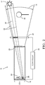
- Fig. 2 illustrates an example of the camera 10 from Fig. 1 that is modified with a light-shield 32 to reduce the intensity of light-rays 34 from the bright-spot 12 in the field-of-view 14 of the camera 10.
- the addition of the light-shield 32 is expected to reduce the light-to-dark contrast of sunlight compared to the surrounding objects 18, from levels as high as 110dB by as much as 46dB. Removing the brightness of the sunlight improves the image-contrast of the remaining scene. This improvement in contrast has the benefit of improved object-detection and improved object-recognition and further allows the use of less expensive vision-systems whose dynamic range is typically limited to less than 70dB.
- the light-shield 32 may be located between the camera-lens 28 and the bright-spot 12, and may be in electrical communication with the controller 30 such that the light-shield 32 may be moved to a position in the line-of-sight 20 with the bright-spot 12 and the imager 16.
- the light-shield 32 may be comprised of a transparent-film 35 that supports an absorber 36 ( Fig. 3 ) sized to block a portion or all of the light-rays 34 of the bright-spot 12 from reaching the imager 16.
- an absorber 36 Fig. 3
- the absorber 36 may be sized to match the resultant circular diameter of the Sun on the visual horizon, based on the distance of the light-shield 32 to the camera-lens 28 and the distance to the imager 16.
- the absorber 36 may be filtered to block a visible-wavelength-camera that is sensitive to wavelengths in the range of four-hundred nanometers (400 nm) to 700 nm, or it may be filtered so that it blocks the near-infrared wavelengths from 700 nm to 1000 nm for use in a night-vision-camera, or it may be filtered so that it blocks both the visible and the near-infrared wavelengths from 400 nm to 1000 nm.
- the opacity of the absorber 36 may be varied across its diameter and may aid the controller 30 in tracking the bright-spot 12.
- the opacity may be varied as multiple concentric circles, where the center of the absorber 36 may the darkest, with each subsequent concentric circle being less opaque.
- the opacity may be a continuous gradient.
- the controller 30 may position the absorber 36 at the limits of the field-of-view 14 to minimize the amount of image-data that is obscured.
- the light-shield 32 may include multiple transparent-films 35 supporting the absorber 36 that may be moved independently from one another to be positioned in the line-of-sight 20 of multiple bright-spots 12.
- a liquid crystal display (LCD), or similar dynamic shape adjustment devices may be used in place of the transparent-film 35 and absorber 36 to reduce the intensity of the light-rays 34 from the bright-spot 12.
- Non-limiting examples of multiple bright-spots 12 may be headlamps from approaching vehicles, and the Sun and reflected sunlight (e.g. glint).
- the position of the bright-spot 12 as detected by the imager 16 may be tracked by the controller 30 across the field-of-view 14.
- the controller 30 may be configured to position the light-shield 32 using ultrasonic linear motors, servo-motors, and other known devices until the intensity of the light-rays 34 from the bright-spot 12 as detected by the imager 16 are minimized. The result is a reduced maximum light level transmitted onto the imager 16 which allows for improved object-detection and improved object-recognition.
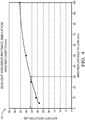
- Fig. 4 is a graph 37 of a simulation of the effect of the light intensity reduction based on the diameter of the absorber 36 and its distance from the camera-lens 28 ( Fig. 2 ). At a distance of thirty millimeters (30mm) from the camera-lens 28 the absorber 36 with a 5mm diameter creates a thirty-six decibel (36dB) intensity reduction of sunlight.
- the 30mm distance to the camera-lens 28 is thought to be a viable placement for the absorber 36 where a windshield-mounted vision-system is used, due to the proximity of the camera-lens 28 to the windshield of the vehicle. While this simulation was performed with a particular design of the camera-lens 28, it would be apparent to one skilled in the art of optics that the output of the simulation will vary based on the design features of the camera-lens 28.
- Fig. 5 illustrates another example of the camera 10 from Fig. 1 that is modified with a light-shield 32 and an aperture-stop 38 to reduce the intensity of the light-rays 34 from the bright-spot 12 in the field-of-view 14 of the camera 10.
- the light-shield 32 may be located between the camera-lens 28 and the aperture-stop 38, and may be in electrical communication with the controller 30 such that the light-shield 32 may be moved to a position in the line-of-sight 20 with the bright-spot 12 and the imager 16. While Fig.
- the aperture-stop 38 between the camera-lens 28 and the imager 16
- the advantages of the camera 10 described herein will also be realized for configurations of cameras 10 where the aperture-stop 38 is located between lens-elements in a multi-lens assembly. That is, the interpretation of the statement that 'an aperture-stop is located between the imager and the camera-lens' includes examples where the aperture-stop 38 is between lens-elements in a multi-lens assembly.
- the aperture-stop 38 may be placed at any location within the multi-lens assembly based on the design of the multi-lens assembly.
- the light-shield 32 is positioned at the aperture-stop 38 of the camera-lens 28 to maximize the light-blocking efficiency, as will be recognized by one skilled in the art of optics.
- the light-shield 32 may be comprised of a transparent-film 35 that supports an absorber 36 sized to block a portion or all of the light-rays 34 of the bright-spot 12 from reaching the imager 16.
- the absorber 36 may be located at the aperture-stop 38 and may be sized to match the resultant circular diameter of the Sun on the visual horizon, based on the position and size of the aperture-stop 38 and the distance to the imager 16.
- the absorber 36 may be filtered to block a visible-wavelength-camera that is sensitive to wavelengths in the range of 400 nm to 700 nm, or it may be filtered so that it blocks the near-infrared wavelengths from 700 nm to 1000 nm for use in a night-vision-camera, or it may be filtered so that it blocks both the visible and the near-infrared wavelengths from 400 nm to 1000 nm.
- Other geometries of the absorber 36 are contemplated and will be recognized by one skilled in the art.
- the opacity of the absorber 36 may be varied across its diameter and may aid the controller 30 in tracking the bright-spot 12.
- the opacity may be varied as multiple concentric circles, where the center of the absorber 36 may be the darkest, with each subsequent concentric circle being less opaque. Alternatively, the opacity may be a continuous gradient.
- the controller 30 may position the absorber 36 at the limits of the field-of-view 14 to minimize the amount of image-data that is obscured.
- the light-shield 32 may include multiple transparent-films 35 supporting the absorber 36 that may be moved independently from one another to be positioned in the line-of-sight 20 of multiple bright-spots 12.
- a liquid crystal display may be used in place of the transparent-film 35 and absorber 36 to reduce the intensity of the light-rays 34 from the bright-spot 12.
- multiple bright-spots 12 may include headlamps from approaching vehicles, and the Sun and reflected sunlight (e.g. glint).
- the position of the bright-spot 12 as detected by the imager 16 may be tracked by the controller 30 across the field-of-view 14.
- the controller 30 may be configured to position the light-shield 32 using ultrasonic linear motors, servo-motors, and other known devices until the intensity of the light-rays 34 from the bright-spot 12 as detected by the imager 16 are minimized. The result is a reduced maximum light level transmitted onto the imager 16 which allows for improved object-detection and improved object-recognition.
- Fig. 6 is a graph 40 of a simulation for the camera 10 of Fig. 5 and quantifies the effect of the light intensity reduction based on the diameter of the absorber 36 located at the aperture-stop 38 of the camera-lens 28.
- the absorber 36 with a 0.32mm diameter creates a 46dB intensity reduction of sunlight.
- Fig. 7 illustrates another example of the camera 10 from Fig. 1 that is modified with a light-shield 32 located in close proximity to the imager 16 to reduce the intensity of the light-rays 34 from the bright-spot 12 in the field-of-view 14 of the camera 10.
- the light-shield 32 may be located between the camera-lens 28 and the imager 16, and may be in electrical communication with the controller 30 such that the light-shield 32 may be moved to a position in the line-of-sight 20 with the bright-spot 12 and the imager 16.
- the light-shield 32 may be comprised of a transparent-film 35 that supports an absorber 36 sized to block a portion or all of the light-rays 34 of the bright-spot 12 from reaching the imager 16.
- the absorber 36 may be sized to match the resultant circular diameter of the Sun on the visual horizon, based on the distance of the light-shield 32 to the camera-lens 28 and the distance to the imager 16.
- the absorber 36 may be filtered to block a visible-wavelength-camera that is sensitive to wavelengths in the range of 400 nm to 700 nm, or it may be filtered so that it blocks the near-infrared wavelengths from 700 nm to 1000 nm for use in a night-vision-camera, or it may be filtered so that it blocks both the visible and the near-infrared wavelengths from 400 nm to 1000 nm.
- the opacity of the absorber 36 may be varied across its diameter and may aid the controller 30 in tracking the bright-spot 12.
- the opacity may be varied as multiple concentric circles, where the center of the absorber 36 may be the darkest, with each subsequent concentric circle being less opaque.
- the opacity may be a continuous gradient.
- the controller 30 may position the absorber 36 at the limits of the field-of-view 14 to minimize the amount of image-data that is obscured.
- the light-shield 32 may include multiple transparent-films 35 supporting the absorber 36 that may be moved independently from one another to be positioned in the line-of-sight 20 of multiple bright-spots 12.
- a liquid crystal display (LCD), or similar dynamic shape adjustment devices may be used in place of the transparent-film 35 and absorber 36 to reduce the intensity of the light-rays 34 from the bright-spot 12.
- Non-limiting examples of multiple bright-spots 12 may include headlamps from approaching vehicles, and the Sun and reflected sunlight (e.g. glint).
- the position of the bright-spot 12 as detected by the imager 16 may be tracked by the controller 30 across the field-of-view 14.
- the controller 30 may be configured to position the light-shield 32 using ultrasonic linear motors, servo-motors, and other known devices until the intensity of the light-rays 34 from the bright-spot 12 as detected by the imager 16 are minimized. The result is a reduced maximum light level transmitted onto the imager 16 which allows for improved object-detection and improved object-recognition.
- Fig. 8 is a graph 42 of a simulation for the camera 10 of Fig. 7 and quantifies the effect of the light intensity reduction based on the diameter of the absorber 36 located a distance of 1mm from the imager 16.
- the absorber 36 with a 0.1mm diameter creates a 30dB intensity reduction of sunlight.
- Contrast improvement for image-elements that are positioned next to the absorber-blocked-image section may be achieved using histogram equalization or other image-processing techniques known in the art.
- the image-area around the absorber-blocked-image may be post-processed to normalize the contrast for the scene-elements that may be affected by the bright-spot-image 26 the absorber-blocked-area. This may be advantageous due to the "haloing effect" that the bright-spot-image 26 imparts around the actual bright-spot-image-area.
- the contrast improvement image-processing may be combined with the absorber-opacity-shape to further reduce the dynamic range of brightness in the image 22.
- a camera system 10 and a controller 30 for the camera system 10 is provided.
- the use of a light-shield 32 solves the problem of a saturated imager 16 causing an object-image 24 to appear much darker than the object 18, and allows for improved object-detection and improved object-recognition.
Landscapes
- Engineering & Computer Science (AREA)
- Physics & Mathematics (AREA)
- Multimedia (AREA)
- Signal Processing (AREA)
- General Physics & Mathematics (AREA)
- Aviation & Aerospace Engineering (AREA)
- Computer Vision & Pattern Recognition (AREA)
- Electromagnetism (AREA)
- Optics & Photonics (AREA)
- Radar, Positioning & Navigation (AREA)
- Remote Sensing (AREA)
- Automation & Control Theory (AREA)
- Studio Devices (AREA)
- Image Processing (AREA)
- Traffic Control Systems (AREA)
- Closed-Circuit Television Systems (AREA)
Abstract
Description
- This disclosure generally relates to a vision system, and more particularly relates to a vision system suitable for use on an automated vehicle.
- It is known that camera systems are severely impaired when a bright light source, such as the Sun or head-lights from an on-coming vehicle for example, is in the direct field-of-view. The light-to-dark contrast of sunlight compared to the surrounding objects may be on the order of one-hundred-ten decibels (110dB) which typically exceeds the linear dynamic range of camera systems. The brightness of the sunlight causes the camera to reduce the exposure times to prevent saturation and consequently lowers the contrast across all image-elements resulting in a darkened image. This causes loss of critical image-data that is required for the vision functions of autonomous-vehicles, such as lane recognition, pedestrian detection, stop-light recognition, vehicle recognition and other autonomous driving object-recognition capabilities. Other vision-systems may be similarly affected such as, robot vision-systems, welding control-systems, military tracking-systems, autonomous vision-systems including space, aircraft and ground based vehicles.
- Described herein is a camera system capable of significantly reducing the dynamic range of brightness of a scene in the field-of-view of the camera.
- In accordance with one embodiment, a camera system suitable for use on an automated vehicle is provided. The camera system includes an imager used to detect an image of a field-of-view of the system. The camera system also includes a light-shield operable to block a portion of the image from being received by the imager. The camera system also includes a controller in communication with the imager and the light-shield, and the controller is configured to position the light-shield in a line-of-sight between a bright-spot and the imager.
- The system may include a camera-lens interposed between the imager and the field-of-view, said camera-lens used to focus the image onto the imager. The light-shield may be interposed between the camera-lens and the bright-spot. The system may include an aperture-stop located between the imager and the camera-lens, and the light-shield is located at the aperture-stop. The light-shield may be located between the camera-lens and the imager. The light-shield may include an absorber supported by a transparent-film.
- Further features and advantages will appear more clearly on a reading of the following detailed description of the preferred embodiment, which is given by way of non-limiting example only and with reference to the accompanying drawings.
- The present invention will now be described, by way of example with reference to the accompanying drawings, in which:
-
Fig. 1 is a prior art camera system in accordance with one embodiment; -
Fig. 2 is a camera system that is modified with a light-shield in accordance with one embodiment; -
Fig. 3 is a light-shield in accordance with one embodiment; -
Fig. 4 is a graph of the light intensity reduction in accordance with one embodiment; -
Fig. 5 is a camera system that is modified with a light-shield and an aperture-stop in accordance with one embodiment; -
Fig. 6 is a graph of the light intensity reduction in accordance with one embodiment; -
Fig. 7 is a camera system that is modified with a light-shield in accordance with one embodiment; and -
Fig. 8 is a graph of the light intensity reduction in accordance with one embodiment. -
Fig. 1 illustrates a non-limiting example of acamera system 10, hereafter referred to as thecamera 10, which may be adversely affected by a bright-spot 12 in a field-of-view 14 of thecamera 10. The intensity of the light from the bright-spot 12, illustrated by the Sun for purposes of example only, may saturate animager 16 of thecamera 10. Both anobject 18 and the bright-spot 12 are in the field-of-view 14. A line-of-sight 20 is defined between the bright-spot 12 and a location on theimager 16 of thecamera 10 where the bright-spot 12 is detected by theimager 16. Theimage 22 includes an object-image 24 and a bright-spot-image 26 and other features not shown that are in the field-of-view 14 of thecamera 10, as will be recognized by one skilled in the art of optics. The adverse result of thesaturated imager 16 is an object-image 24 that appears to be much darker than theobject 18. Theobject 18 may be a street sign, a lane marking, or a pedestrian for example, that may become undetectable by thecamera 10 due to the saturation of theimager 16. Theimage 22 is shown inverted on theimager 16 as the rays of light pass through a single camera-lens 28 by way of a non-limiting example only. Multiple camera-lenses 28 of varying geometries may be used in thecamera 10, as will be recognized by one skilled in the art of optics. Theimager 16 may be in electrical communication with acontroller 30 to process theimage 22 based on the application of thecamera 10 as will be recognized by one skilled in the art of vision-systems. -
Fig. 2 illustrates an example of thecamera 10 fromFig. 1 that is modified with a light-shield 32 to reduce the intensity of light-rays 34 from the bright-spot 12 in the field-of-view 14 of thecamera 10. The addition of the light-shield 32 is expected to reduce the light-to-dark contrast of sunlight compared to the surroundingobjects 18, from levels as high as 110dB by as much as 46dB. Removing the brightness of the sunlight improves the image-contrast of the remaining scene. This improvement in contrast has the benefit of improved object-detection and improved object-recognition and further allows the use of less expensive vision-systems whose dynamic range is typically limited to less than 70dB. The light-shield 32 may be located between the camera-lens 28 and the bright-spot 12, and may be in electrical communication with thecontroller 30 such that the light-shield 32 may be moved to a position in the line-of-sight 20 with the bright-spot 12 and theimager 16. The light-shield 32 may be comprised of a transparent-film 35 that supports an absorber 36 (Fig. 3 ) sized to block a portion or all of the light-rays 34 of the bright-spot 12 from reaching theimager 16. In the non-limiting example illustrated inFig. 2 , theabsorber 36 may be sized to match the resultant circular diameter of the Sun on the visual horizon, based on the distance of the light-shield 32 to the camera-lens 28 and the distance to theimager 16. Theabsorber 36 may be filtered to block a visible-wavelength-camera that is sensitive to wavelengths in the range of four-hundred nanometers (400 nm) to 700 nm, or it may be filtered so that it blocks the near-infrared wavelengths from 700 nm to 1000 nm for use in a night-vision-camera, or it may be filtered so that it blocks both the visible and the near-infrared wavelengths from 400 nm to 1000 nm. Other geometries of theabsorber 36 are contemplated and will be recognized by one skilled in the art. The opacity of theabsorber 36 may be varied across its diameter and may aid thecontroller 30 in tracking the bright-spot 12. The opacity may be varied as multiple concentric circles, where the center of theabsorber 36 may the darkest, with each subsequent concentric circle being less opaque. Alternatively, the opacity may be a continuous gradient. When the bright-spot 12 is not detected by theimager 16 thecontroller 30 may position the absorber 36 at the limits of the field-of-view 14 to minimize the amount of image-data that is obscured. The light-shield 32 may include multiple transparent-films 35 supporting theabsorber 36 that may be moved independently from one another to be positioned in the line-of-sight 20 of multiple bright-spots 12. Alternatively a liquid crystal display (LCD), or similar dynamic shape adjustment devices, may be used in place of the transparent-film 35 and absorber 36 to reduce the intensity of the light-rays 34 from the bright-spot 12. Non-limiting examples of multiple bright-spots 12 may be headlamps from approaching vehicles, and the Sun and reflected sunlight (e.g. glint). The position of the bright-spot 12 as detected by theimager 16 may be tracked by thecontroller 30 across the field-of-view 14. Thecontroller 30 may be configured to position the light-shield 32 using ultrasonic linear motors, servo-motors, and other known devices until the intensity of the light-rays 34 from the bright-spot 12 as detected by theimager 16 are minimized. The result is a reduced maximum light level transmitted onto theimager 16 which allows for improved object-detection and improved object-recognition. - The location of the light-
shield 32 relative to theimager 16, and the size of theabsorber 36, affects the reduction in light intensity of the incoming light-rays 34.Fig. 4 is agraph 37 of a simulation of the effect of the light intensity reduction based on the diameter of theabsorber 36 and its distance from the camera-lens 28 (Fig. 2 ). At a distance of thirty millimeters (30mm) from the camera-lens 28 the absorber 36 with a 5mm diameter creates a thirty-six decibel (36dB) intensity reduction of sunlight. The 30mm distance to the camera-lens 28 is thought to be a viable placement for theabsorber 36 where a windshield-mounted vision-system is used, due to the proximity of the camera-lens 28 to the windshield of the vehicle. While this simulation was performed with a particular design of the camera-lens 28, it would be apparent to one skilled in the art of optics that the output of the simulation will vary based on the design features of the camera-lens 28. -
Fig. 5 illustrates another example of thecamera 10 fromFig. 1 that is modified with a light-shield 32 and an aperture-stop 38 to reduce the intensity of the light-rays 34 from the bright-spot 12 in the field-of-view 14 of thecamera 10. The light-shield 32 may be located between the camera-lens 28 and the aperture-stop 38, and may be in electrical communication with thecontroller 30 such that the light-shield 32 may be moved to a position in the line-of-sight 20 with the bright-spot 12 and theimager 16. WhileFig. 5 shows the aperture-stop 38 between the camera-lens 28 and theimager 16, it is contemplated that the advantages of thecamera 10 described herein will also be realized for configurations ofcameras 10 where the aperture-stop 38 is located between lens-elements in a multi-lens assembly. That is, the interpretation of the statement that 'an aperture-stop is located between the imager and the camera-lens' includes examples where the aperture-stop 38 is between lens-elements in a multi-lens assembly. Additionally, the aperture-stop 38 may be placed at any location within the multi-lens assembly based on the design of the multi-lens assembly. Advantageously, the light-shield 32 is positioned at the aperture-stop 38 of the camera-lens 28 to maximize the light-blocking efficiency, as will be recognized by one skilled in the art of optics. The light-shield 32 may be comprised of a transparent-film 35 that supports an absorber 36 sized to block a portion or all of the light-rays 34 of the bright-spot 12 from reaching theimager 16. In the non-limiting example illustrated inFig. 5 , theabsorber 36 may be located at the aperture-stop 38 and may be sized to match the resultant circular diameter of the Sun on the visual horizon, based on the position and size of the aperture-stop 38 and the distance to theimager 16. Theabsorber 36 may be filtered to block a visible-wavelength-camera that is sensitive to wavelengths in the range of 400 nm to 700 nm, or it may be filtered so that it blocks the near-infrared wavelengths from 700 nm to 1000 nm for use in a night-vision-camera, or it may be filtered so that it blocks both the visible and the near-infrared wavelengths from 400 nm to 1000 nm. Other geometries of theabsorber 36 are contemplated and will be recognized by one skilled in the art. The opacity of theabsorber 36 may be varied across its diameter and may aid thecontroller 30 in tracking the bright-spot 12. The opacity may be varied as multiple concentric circles, where the center of theabsorber 36 may be the darkest, with each subsequent concentric circle being less opaque. Alternatively, the opacity may be a continuous gradient. When the bright-spot 12 is not detected by theimager 16 thecontroller 30 may position theabsorber 36 at the limits of the field-of-view 14 to minimize the amount of image-data that is obscured. The light-shield 32 may include multiple transparent-films 35 supporting theabsorber 36 that may be moved independently from one another to be positioned in the line-of-sight 20 of multiple bright-spots 12. Alternatively a liquid crystal display (LCD), or similar dynamic shape adjustment devices, may be used in place of the transparent-film 35 andabsorber 36 to reduce the intensity of the light-rays 34 from the bright-spot 12. Non-limiting examples of multiple bright-spots 12 may include headlamps from approaching vehicles, and the Sun and reflected sunlight (e.g. glint). The position of the bright-spot 12 as detected by theimager 16 may be tracked by thecontroller 30 across the field-of-view 14. Thecontroller 30 may be configured to position the light-shield 32 using ultrasonic linear motors, servo-motors, and other known devices until the intensity of the light-rays 34 from the bright-spot 12 as detected by theimager 16 are minimized. The result is a reduced maximum light level transmitted onto theimager 16 which allows for improved object-detection and improved object-recognition. -
Fig. 6 is agraph 40 of a simulation for thecamera 10 ofFig. 5 and quantifies the effect of the light intensity reduction based on the diameter of theabsorber 36 located at the aperture-stop 38 of the camera-lens 28. Theabsorber 36 with a 0.32mm diameter creates a 46dB intensity reduction of sunlight. -
Fig. 7 illustrates another example of thecamera 10 fromFig. 1 that is modified with a light-shield 32 located in close proximity to theimager 16 to reduce the intensity of the light-rays 34 from the bright-spot 12 in the field-of-view 14 of thecamera 10. The light-shield 32 may be located between the camera-lens 28 and theimager 16, and may be in electrical communication with thecontroller 30 such that the light-shield 32 may be moved to a position in the line-of-sight 20 with the bright-spot 12 and theimager 16. The light-shield 32 may be comprised of a transparent-film 35 that supports an absorber 36 sized to block a portion or all of the light-rays 34 of the bright-spot 12 from reaching theimager 16. In the non-limiting example illustrated inFig. 7 , theabsorber 36 may be sized to match the resultant circular diameter of the Sun on the visual horizon, based on the distance of the light-shield 32 to the camera-lens 28 and the distance to theimager 16. Theabsorber 36 may be filtered to block a visible-wavelength-camera that is sensitive to wavelengths in the range of 400 nm to 700 nm, or it may be filtered so that it blocks the near-infrared wavelengths from 700 nm to 1000 nm for use in a night-vision-camera, or it may be filtered so that it blocks both the visible and the near-infrared wavelengths from 400 nm to 1000 nm. Other geometries of theabsorber 36 are contemplated and will be recognized by one skilled in the art. The opacity of theabsorber 36 may be varied across its diameter and may aid thecontroller 30 in tracking the bright-spot 12. The opacity may be varied as multiple concentric circles, where the center of theabsorber 36 may be the darkest, with each subsequent concentric circle being less opaque. Alternatively, the opacity may be a continuous gradient. When the bright-spot 12 is not detected by theimager 16 thecontroller 30 may position theabsorber 36 at the limits of the field-of-view 14 to minimize the amount of image-data that is obscured. The light-shield 32 may include multiple transparent-films 35 supporting theabsorber 36 that may be moved independently from one another to be positioned in the line-of-sight 20 of multiple bright-spots 12. Alternatively a liquid crystal display (LCD), or similar dynamic shape adjustment devices, may be used in place of the transparent-film 35 andabsorber 36 to reduce the intensity of the light-rays 34 from the bright-spot 12. Non-limiting examples of multiple bright-spots 12 may include headlamps from approaching vehicles, and the Sun and reflected sunlight (e.g. glint). The position of the bright-spot 12 as detected by theimager 16 may be tracked by thecontroller 30 across the field-of-view 14. Thecontroller 30 may be configured to position the light-shield 32 using ultrasonic linear motors, servo-motors, and other known devices until the intensity of the light-rays 34 from the bright-spot 12 as detected by theimager 16 are minimized. The result is a reduced maximum light level transmitted onto theimager 16 which allows for improved object-detection and improved object-recognition. -
Fig. 8 is agraph 42 of a simulation for thecamera 10 ofFig. 7 and quantifies the effect of the light intensity reduction based on the diameter of theabsorber 36 located a distance of 1mm from theimager 16. Theabsorber 36 with a 0.1mm diameter creates a 30dB intensity reduction of sunlight. - Contrast improvement for image-elements that are positioned next to the absorber-blocked-image section (e.g. approximately two to five times the absorber-blocked-image area) may be achieved using histogram equalization or other image-processing techniques known in the art. The image-area around the absorber-blocked-image may be post-processed to normalize the contrast for the scene-elements that may be affected by the bright-spot-
image 26 the absorber-blocked-area. This may be advantageous due to the "haloing effect" that the bright-spot-image 26 imparts around the actual bright-spot-image-area. The contrast improvement image-processing may be combined with the absorber-opacity-shape to further reduce the dynamic range of brightness in theimage 22. - Accordingly, a
camera system 10, and acontroller 30 for thecamera system 10 is provided. The use of a light-shield 32 solves the problem of a saturatedimager 16 causing an object-image 24 to appear much darker than theobject 18, and allows for improved object-detection and improved object-recognition. - While this invention has been described in terms of the preferred embodiments thereof, it is not intended to be so limited, but rather only to the extent set forth in the claims that follow.
Claims (6)
- A camera system (10) suitable for use on an automated vehicle, said system (10) comprising:an imager (16) used to detect an image (22) of a field-of-view (14) of the system (10);a light-shield (32) operable to block a portion of the image (22) from being received by the imager (16); anda controller (30) in communication with the imager (16) and the light-shield (32), said controller (30) configured to position the light-shield (32) in a line-of-sight (20) between a bright-spot (12) and the imager (16).
- The system (10) in accordance with claim 1, wherein the system (10) includes a camera-lens (28) interposed between the imager (16) and the field-of-view (14), said camera-lens (28) used to focus the image (22) onto the imager (16).
- The system (10) in accordance with claim 2, wherein the light-shield (32) is interposed between the camera-lens (28) and the bright-spot (12).
- The system (10) according to any one of the claims 2 to 3, wherein the system (10) includes an aperture-stop (38) located between the imager (16) and the camera-lens (28), and the light-shield (32) is located at the aperture-stop (38).
- The system (10) according to any one of the claims 2 to 4, wherein the light-shield (32) is located between the camera-lens (28) and the imager (16).
- The system (10) according to any one of the preceding claims, wherein the light-shield (32) includes an absorber (36) supported by a transparent-film (35).
Applications Claiming Priority (1)
| Application Number | Priority Date | Filing Date | Title |
|---|---|---|---|
| US15/180,271 US10462380B2 (en) | 2016-06-13 | 2016-06-13 | Camera system with light-shield |
Publications (2)
| Publication Number | Publication Date |
|---|---|
| EP3258313A1 true EP3258313A1 (en) | 2017-12-20 |
| EP3258313B1 EP3258313B1 (en) | 2021-08-04 |
Family
ID=59276490
Family Applications (1)
| Application Number | Title | Priority Date | Filing Date |
|---|---|---|---|
| EP17175717.2A Active EP3258313B1 (en) | 2016-06-13 | 2017-06-13 | Sunlight glare reduction system |
Country Status (3)
| Country | Link |
|---|---|
| US (2) | US10462380B2 (en) |
| EP (1) | EP3258313B1 (en) |
| CN (1) | CN107493408A (en) |
Cited By (2)
| Publication number | Priority date | Publication date | Assignee | Title |
|---|---|---|---|---|
| GB2632273A (en) * | 2023-07-28 | 2025-02-05 | Mercedes Benz Group Ag | A camera device for capturing the surroundings of a motor vehicle, a method for controlling a camera device, a computer program product, as well as a... |
| EP4641264A3 (en) * | 2024-04-25 | 2025-12-17 | Tesla, Inc. | Cone-textured glare shield for enhanced camera vision |
Families Citing this family (17)
| Publication number | Priority date | Publication date | Assignee | Title |
|---|---|---|---|---|
| US10462380B2 (en) | 2016-06-13 | 2019-10-29 | Aptiv Technologies Limited | Camera system with light-shield |
| US10356335B2 (en) * | 2016-09-23 | 2019-07-16 | Apple Inc. | Camera shades |
| US10345562B2 (en) * | 2017-02-07 | 2019-07-09 | Raytheon Company | All-reflective solar coronagraph sensor and thermal control subsystem |
| US10315496B2 (en) * | 2017-08-11 | 2019-06-11 | GM Global Technology Operations LLC | Systems and methods for sun protection |
| US10148891B1 (en) * | 2017-08-24 | 2018-12-04 | Tzu-Ping Hsu | Card operation device for controlling exposure time |
| US11184510B2 (en) * | 2018-04-13 | 2021-11-23 | Panavision International, L.P. | Electronic camera filter |
| US12316939B2 (en) | 2018-04-13 | 2025-05-27 | Panavision International, L.P. | Camera lens system filter |
| US10845582B2 (en) * | 2018-06-07 | 2020-11-24 | Raytheon Company | All-reflective solar coronagraph sensor and thermal control subsystem |
| EP3605384B1 (en) | 2018-08-03 | 2025-12-31 | Aptiv Technologies AG | DEVICE AND METHOD FOR DETECTING VEHICLE LIGHTS IN AN IMAGE |
| DE102018213078B4 (en) * | 2018-08-06 | 2020-06-18 | Zf Friedrichshafen Ag | Blackout device for an ADAS camera, control unit for an ADAS camera system, ADAS camera system and vehicle with an ADAS camera system |
| FR3088790B1 (en) * | 2018-11-20 | 2020-11-27 | Safran Electronics & Defense | Apparatus and method for observing a scene including a target |
| CN110287797B (en) * | 2019-05-24 | 2020-06-12 | 北京爱诺斯科技有限公司 | Refractive screening method based on mobile phone |
| US11537027B2 (en) * | 2020-01-19 | 2022-12-27 | Blue River Technology Inc. | Methods and apparatus for using a controllable physical light filter as part of an image capture system and for processing captured images |
| RU2754303C1 (en) * | 2020-05-31 | 2021-08-31 | Владимир Эльич Пашковский | Method for reducing the impact of interference when shooting low-glow objects |
| US11418728B1 (en) * | 2021-02-11 | 2022-08-16 | Aptiv Technologies Limited | Programmable liquid crystal vignetting element with selective shading feature |
| CN114093291A (en) * | 2021-12-27 | 2022-02-25 | 优奈柯恩(北京)科技有限公司 | Head-mounted display device, system and method for adjusting display brightness of device |
| JP2024092234A (en) * | 2022-12-26 | 2024-07-08 | レノボ・シンガポール・プライベート・リミテッド | Electronic device and method for manufacturing electronic device |
Citations (5)
| Publication number | Priority date | Publication date | Assignee | Title |
|---|---|---|---|---|
| US5541705A (en) * | 1994-01-12 | 1996-07-30 | Kan; Michael | Camera with large dynamic range |
| DE19916000A1 (en) * | 1999-04-09 | 2000-10-12 | Harald Paleske | Coronographic optical system is for astronomical observation of manifestations on sun, such as sun spots, flares, protuberances in spectral and neutral light, chromosphere at sun edge, moon, planets and double stars |
| US20020071185A1 (en) * | 2000-12-07 | 2002-06-13 | Jean-Loup Chretien | System and method for dynamic optical filtration |
| US20150092083A1 (en) * | 2013-09-30 | 2015-04-02 | Nghia Trong Lam | Active Shielding Against Intense Illumination (ASAII) System for Direct Viewing |
| US20150163389A1 (en) * | 2013-12-06 | 2015-06-11 | Chung-Shan Institute Of Science And Technology, Armaments Bureau, M.N.D | Exposure-suppressing imaging system |
Family Cites Families (27)
| Publication number | Priority date | Publication date | Assignee | Title |
|---|---|---|---|---|
| US3397023A (en) * | 1964-12-16 | 1968-08-13 | Polaroid Corp | Light apertures |
| US5479298A (en) * | 1991-12-20 | 1995-12-26 | Canon Denshi Kabushiki Kaisha | ND filter and aperture device using the same |
| US5523811A (en) * | 1992-04-17 | 1996-06-04 | Canon Kabushiki Kaisha | Camera device for moving body |
| US5387958A (en) * | 1992-06-30 | 1995-02-07 | Sony Electronics, Inc. | Electro-optical control of light attenuation in the optical path of a camera |
| JPH10145668A (en) * | 1996-11-14 | 1998-05-29 | Nikon Corp | Polarizing filter control mechanism |
| JPH10327337A (en) * | 1997-05-23 | 1998-12-08 | Fuji Heavy Ind Ltd | Smearing prevention device for image input device |
| JP4273372B2 (en) * | 1998-07-31 | 2009-06-03 | ソニー株式会社 | Imaging device |
| US7245325B2 (en) * | 2000-03-17 | 2007-07-17 | Fujifilm Corporation | Photographing device with light quantity adjustment |
| US20020131170A1 (en) * | 2001-01-12 | 2002-09-19 | Bryan Costales | Stereoscopic aperture valves |
| WO2003074307A1 (en) * | 2002-03-07 | 2003-09-12 | Yechezkal Evan Spero | Enhanced vision for driving |
| US7453514B2 (en) * | 2003-05-07 | 2008-11-18 | Pure Digital Technologies, Inc. | Digital photography device having a rolling shutter |
| JP4262566B2 (en) * | 2003-10-16 | 2009-05-13 | 株式会社日立製作所 | In-vehicle imaging device and camera |
| US7830561B2 (en) * | 2005-03-16 | 2010-11-09 | The Trustees Of Columbia University In The City Of New York | Lensless imaging with controllable apertures |
| US20070242141A1 (en) * | 2006-04-14 | 2007-10-18 | Sony Corporation And Sony Electronics Inc. | Adjustable neutral density filter system for dynamic range compression from scene to imaging sensor |
| JP4510783B2 (en) * | 2006-05-23 | 2010-07-28 | キヤノン株式会社 | Optical equipment |
| US8589034B2 (en) * | 2008-10-09 | 2013-11-19 | Angela Karen Kwok | System and methods for an automated sun glare block area and sunshield in a vehicular windshield |
| US20110141336A1 (en) * | 2009-12-11 | 2011-06-16 | Apple Inc. | Photochromatic coating for controlling lens flare |
| US20120075518A1 (en) * | 2010-09-29 | 2012-03-29 | Hoya Corporation | Imaging unit |
| JP2012075037A (en) * | 2010-09-29 | 2012-04-12 | Murakami Corp | Color camera |
| WO2012097163A1 (en) * | 2011-01-14 | 2012-07-19 | The Board Of Trustees Of The University Of Illinois | Optical component array having adjustable curvature |
| JP6120395B2 (en) * | 2012-07-03 | 2017-04-26 | クラリオン株式会社 | In-vehicle device |
| EP2879111A4 (en) * | 2012-07-27 | 2016-10-19 | Clarion Co Ltd | Image processing device |
| US10553002B2 (en) * | 2012-08-31 | 2020-02-04 | Apple, Inc. | Information display using electronic diffusers |
| US9409464B2 (en) * | 2013-04-25 | 2016-08-09 | Globalfoundries Inc. | Dynamically managing vehicle glass dimming |
| CN105594197A (en) * | 2013-09-27 | 2016-05-18 | 富士胶片株式会社 | Imaging device and imaging method |
| US9904146B2 (en) * | 2015-10-29 | 2018-02-27 | GM Global Technology Operations LLC | Camera with positionable light shade |
| US10462380B2 (en) | 2016-06-13 | 2019-10-29 | Aptiv Technologies Limited | Camera system with light-shield |
-
2016
- 2016-06-13 US US15/180,271 patent/US10462380B2/en active Active
-
2017
- 2017-06-12 CN CN201710439521.0A patent/CN107493408A/en active Pending
- 2017-06-13 EP EP17175717.2A patent/EP3258313B1/en active Active
-
2019
- 2019-09-16 US US16/571,573 patent/US11032488B2/en active Active
Patent Citations (5)
| Publication number | Priority date | Publication date | Assignee | Title |
|---|---|---|---|---|
| US5541705A (en) * | 1994-01-12 | 1996-07-30 | Kan; Michael | Camera with large dynamic range |
| DE19916000A1 (en) * | 1999-04-09 | 2000-10-12 | Harald Paleske | Coronographic optical system is for astronomical observation of manifestations on sun, such as sun spots, flares, protuberances in spectral and neutral light, chromosphere at sun edge, moon, planets and double stars |
| US20020071185A1 (en) * | 2000-12-07 | 2002-06-13 | Jean-Loup Chretien | System and method for dynamic optical filtration |
| US20150092083A1 (en) * | 2013-09-30 | 2015-04-02 | Nghia Trong Lam | Active Shielding Against Intense Illumination (ASAII) System for Direct Viewing |
| US20150163389A1 (en) * | 2013-12-06 | 2015-06-11 | Chung-Shan Institute Of Science And Technology, Armaments Bureau, M.N.D | Exposure-suppressing imaging system |
Cited By (2)
| Publication number | Priority date | Publication date | Assignee | Title |
|---|---|---|---|---|
| GB2632273A (en) * | 2023-07-28 | 2025-02-05 | Mercedes Benz Group Ag | A camera device for capturing the surroundings of a motor vehicle, a method for controlling a camera device, a computer program product, as well as a... |
| EP4641264A3 (en) * | 2024-04-25 | 2025-12-17 | Tesla, Inc. | Cone-textured glare shield for enhanced camera vision |
Also Published As
| Publication number | Publication date |
|---|---|
| US20170359495A1 (en) | 2017-12-14 |
| US20200014834A1 (en) | 2020-01-09 |
| US11032488B2 (en) | 2021-06-08 |
| US10462380B2 (en) | 2019-10-29 |
| EP3258313B1 (en) | 2021-08-04 |
| CN107493408A (en) | 2017-12-19 |
Similar Documents
| Publication | Publication Date | Title |
|---|---|---|
| EP3258313B1 (en) | Sunlight glare reduction system | |
| US11938795B2 (en) | Vehicular vision system with glare reducing windshield | |
| US10564267B2 (en) | High dynamic range imaging of environment with a high intensity reflecting/transmitting source | |
| US11163977B2 (en) | Capturing camera | |
| US11117529B2 (en) | Capturing camera | |
| US9323053B2 (en) | Active shielding against intense illumination (ASAII) system for direct viewing | |
| US10377212B2 (en) | Dynamic anti-glare system for a windshield of a vehicle | |
| US9304301B2 (en) | Camera hardware design for dynamic rearview mirror | |
| JP2020522937A (en) | Shutterless Far Infrared (FIR) Camera for Automotive Safety and Driving Systems | |
| EP3340600A1 (en) | Lens, camera, package inspection system and image processing method | |
| US20200290440A1 (en) | Vehicle antiglare system and method and vehicle comprising antiglare system | |
| DE102008043880A1 (en) | Lighting unit for a vehicle, vehicle and method therefor | |
| CN205010094U (en) | Vehicle HUD system | |
| CN105635679A (en) | Active anti-glare night vision system of vehicle-mounted special device and realization method | |
| CN118849728B (en) | A windshield control method, system, device, and automobile | |
| CN104811614B (en) | Camera system for a vehicle and method for determining image information of a time pulse signal source | |
| JP6277698B2 (en) | Projector for vehicle | |
| JP2006527387A (en) | Drive assist device | |
| CN110341602A (en) | A kind of automobile front and rear windshield auxiliary display system and display methods | |
| CN104360494A (en) | Digital video anti-dazzle glasses | |
| CN206946130U (en) | A device that selectively blocks part of the field of view | |
| JP2004325202A (en) | Laser radar device | |
| EP3284641A1 (en) | Dual-focus camera for automated vehicles | |
| WO2025216646A1 (en) | Attenuation of light glare and dazzling prevention | |
| CN122008821A (en) | Intelligent vision protection method, device, equipment and storage medium for relieving vehicle high beam glare |
Legal Events
| Date | Code | Title | Description |
|---|---|---|---|
| PUAI | Public reference made under article 153(3) epc to a published international application that has entered the european phase |
Free format text: ORIGINAL CODE: 0009012 |
|
| STAA | Information on the status of an ep patent application or granted ep patent |
Free format text: STATUS: THE APPLICATION HAS BEEN PUBLISHED |
|
| AK | Designated contracting states |
Kind code of ref document: A1 Designated state(s): AL AT BE BG CH CY CZ DE DK EE ES FI FR GB GR HR HU IE IS IT LI LT LU LV MC MK MT NL NO PL PT RO RS SE SI SK SM TR |
|
| AX | Request for extension of the european patent |
Extension state: BA ME |
|
| STAA | Information on the status of an ep patent application or granted ep patent |
Free format text: STATUS: REQUEST FOR EXAMINATION WAS MADE |
|
| 17P | Request for examination filed |
Effective date: 20180620 |
|
| RBV | Designated contracting states (corrected) |
Designated state(s): AL AT BE BG CH CY CZ DE DK EE ES FI FR GB GR HR HU IE IS IT LI LT LU LV MC MK MT NL NO PL PT RO RS SE SI SK SM TR |
|
| RAP1 | Party data changed (applicant data changed or rights of an application transferred) |
Owner name: APTIV TECHNOLOGIES LIMITED |
|
| STAA | Information on the status of an ep patent application or granted ep patent |
Free format text: STATUS: EXAMINATION IS IN PROGRESS |
|
| 17Q | First examination report despatched |
Effective date: 20200103 |
|
| RIC1 | Information provided on ipc code assigned before grant |
Ipc: G03B 11/02 20060101AFI20201130BHEP Ipc: H04N 5/238 20060101ALI20201130BHEP Ipc: G03B 11/04 20060101ALN20201130BHEP |
|
| GRAP | Despatch of communication of intention to grant a patent |
Free format text: ORIGINAL CODE: EPIDOSNIGR1 |
|
| STAA | Information on the status of an ep patent application or granted ep patent |
Free format text: STATUS: GRANT OF PATENT IS INTENDED |
|
| INTG | Intention to grant announced |
Effective date: 20210112 |
|
| GRAS | Grant fee paid |
Free format text: ORIGINAL CODE: EPIDOSNIGR3 |
|
| GRAA | (expected) grant |
Free format text: ORIGINAL CODE: 0009210 |
|
| STAA | Information on the status of an ep patent application or granted ep patent |
Free format text: STATUS: THE PATENT HAS BEEN GRANTED |
|
| AK | Designated contracting states |
Kind code of ref document: B1 Designated state(s): AL AT BE BG CH CY CZ DE DK EE ES FI FR GB GR HR HU IE IS IT LI LT LU LV MC MK MT NL NO PL PT RO RS SE SI SK SM TR |
|
| REG | Reference to a national code |
Ref country code: GB Ref legal event code: FG4D |
|
| REG | Reference to a national code |
Ref country code: AT Ref legal event code: REF Ref document number: 1417587 Country of ref document: AT Kind code of ref document: T Effective date: 20210815 |
|
| REG | Reference to a national code |
Ref country code: CH Ref legal event code: EP |
|
| REG | Reference to a national code |
Ref country code: DE Ref legal event code: R096 Ref document number: 602017043224 Country of ref document: DE |
|
| REG | Reference to a national code |
Ref country code: IE Ref legal event code: FG4D |
|
| REG | Reference to a national code |
Ref country code: LT Ref legal event code: MG9D |
|
| REG | Reference to a national code |
Ref country code: NL Ref legal event code: MP Effective date: 20210804 |
|
| REG | Reference to a national code |
Ref country code: AT Ref legal event code: MK05 Ref document number: 1417587 Country of ref document: AT Kind code of ref document: T Effective date: 20210804 |
|
| PG25 | Lapsed in a contracting state [announced via postgrant information from national office to epo] |
Ref country code: RS Free format text: LAPSE BECAUSE OF FAILURE TO SUBMIT A TRANSLATION OF THE DESCRIPTION OR TO PAY THE FEE WITHIN THE PRESCRIBED TIME-LIMIT Effective date: 20210804 Ref country code: SE Free format text: LAPSE BECAUSE OF FAILURE TO SUBMIT A TRANSLATION OF THE DESCRIPTION OR TO PAY THE FEE WITHIN THE PRESCRIBED TIME-LIMIT Effective date: 20210804 Ref country code: NO Free format text: LAPSE BECAUSE OF FAILURE TO SUBMIT A TRANSLATION OF THE DESCRIPTION OR TO PAY THE FEE WITHIN THE PRESCRIBED TIME-LIMIT Effective date: 20211104 Ref country code: PT Free format text: LAPSE BECAUSE OF FAILURE TO SUBMIT A TRANSLATION OF THE DESCRIPTION OR TO PAY THE FEE WITHIN THE PRESCRIBED TIME-LIMIT Effective date: 20211206 Ref country code: HR Free format text: LAPSE BECAUSE OF FAILURE TO SUBMIT A TRANSLATION OF THE DESCRIPTION OR TO PAY THE FEE WITHIN THE PRESCRIBED TIME-LIMIT Effective date: 20210804 Ref country code: FI Free format text: LAPSE BECAUSE OF FAILURE TO SUBMIT A TRANSLATION OF THE DESCRIPTION OR TO PAY THE FEE WITHIN THE PRESCRIBED TIME-LIMIT Effective date: 20210804 Ref country code: ES Free format text: LAPSE BECAUSE OF FAILURE TO SUBMIT A TRANSLATION OF THE DESCRIPTION OR TO PAY THE FEE WITHIN THE PRESCRIBED TIME-LIMIT Effective date: 20210804 Ref country code: LT Free format text: LAPSE BECAUSE OF FAILURE TO SUBMIT A TRANSLATION OF THE DESCRIPTION OR TO PAY THE FEE WITHIN THE PRESCRIBED TIME-LIMIT Effective date: 20210804 Ref country code: BG Free format text: LAPSE BECAUSE OF FAILURE TO SUBMIT A TRANSLATION OF THE DESCRIPTION OR TO PAY THE FEE WITHIN THE PRESCRIBED TIME-LIMIT Effective date: 20211104 Ref country code: AT Free format text: LAPSE BECAUSE OF FAILURE TO SUBMIT A TRANSLATION OF THE DESCRIPTION OR TO PAY THE FEE WITHIN THE PRESCRIBED TIME-LIMIT Effective date: 20210804 |
|
| PG25 | Lapsed in a contracting state [announced via postgrant information from national office to epo] |
Ref country code: PL Free format text: LAPSE BECAUSE OF FAILURE TO SUBMIT A TRANSLATION OF THE DESCRIPTION OR TO PAY THE FEE WITHIN THE PRESCRIBED TIME-LIMIT Effective date: 20210804 Ref country code: LV Free format text: LAPSE BECAUSE OF FAILURE TO SUBMIT A TRANSLATION OF THE DESCRIPTION OR TO PAY THE FEE WITHIN THE PRESCRIBED TIME-LIMIT Effective date: 20210804 Ref country code: GR Free format text: LAPSE BECAUSE OF FAILURE TO SUBMIT A TRANSLATION OF THE DESCRIPTION OR TO PAY THE FEE WITHIN THE PRESCRIBED TIME-LIMIT Effective date: 20211105 |
|
| PG25 | Lapsed in a contracting state [announced via postgrant information from national office to epo] |
Ref country code: NL Free format text: LAPSE BECAUSE OF FAILURE TO SUBMIT A TRANSLATION OF THE DESCRIPTION OR TO PAY THE FEE WITHIN THE PRESCRIBED TIME-LIMIT Effective date: 20210804 |
|
| PG25 | Lapsed in a contracting state [announced via postgrant information from national office to epo] |
Ref country code: DK Free format text: LAPSE BECAUSE OF FAILURE TO SUBMIT A TRANSLATION OF THE DESCRIPTION OR TO PAY THE FEE WITHIN THE PRESCRIBED TIME-LIMIT Effective date: 20210804 |
|
| REG | Reference to a national code |
Ref country code: DE Ref legal event code: R097 Ref document number: 602017043224 Country of ref document: DE |
|
| PG25 | Lapsed in a contracting state [announced via postgrant information from national office to epo] |
Ref country code: SM Free format text: LAPSE BECAUSE OF FAILURE TO SUBMIT A TRANSLATION OF THE DESCRIPTION OR TO PAY THE FEE WITHIN THE PRESCRIBED TIME-LIMIT Effective date: 20210804 Ref country code: SK Free format text: LAPSE BECAUSE OF FAILURE TO SUBMIT A TRANSLATION OF THE DESCRIPTION OR TO PAY THE FEE WITHIN THE PRESCRIBED TIME-LIMIT Effective date: 20210804 Ref country code: RO Free format text: LAPSE BECAUSE OF FAILURE TO SUBMIT A TRANSLATION OF THE DESCRIPTION OR TO PAY THE FEE WITHIN THE PRESCRIBED TIME-LIMIT Effective date: 20210804 Ref country code: EE Free format text: LAPSE BECAUSE OF FAILURE TO SUBMIT A TRANSLATION OF THE DESCRIPTION OR TO PAY THE FEE WITHIN THE PRESCRIBED TIME-LIMIT Effective date: 20210804 Ref country code: CZ Free format text: LAPSE BECAUSE OF FAILURE TO SUBMIT A TRANSLATION OF THE DESCRIPTION OR TO PAY THE FEE WITHIN THE PRESCRIBED TIME-LIMIT Effective date: 20210804 Ref country code: AL Free format text: LAPSE BECAUSE OF FAILURE TO SUBMIT A TRANSLATION OF THE DESCRIPTION OR TO PAY THE FEE WITHIN THE PRESCRIBED TIME-LIMIT Effective date: 20210804 |
|
| PLBE | No opposition filed within time limit |
Free format text: ORIGINAL CODE: 0009261 |
|
| STAA | Information on the status of an ep patent application or granted ep patent |
Free format text: STATUS: NO OPPOSITION FILED WITHIN TIME LIMIT |
|
| 26N | No opposition filed |
Effective date: 20220506 |
|
| PG25 | Lapsed in a contracting state [announced via postgrant information from national office to epo] |
Ref country code: IT Free format text: LAPSE BECAUSE OF FAILURE TO SUBMIT A TRANSLATION OF THE DESCRIPTION OR TO PAY THE FEE WITHIN THE PRESCRIBED TIME-LIMIT Effective date: 20210804 |
|
| PG25 | Lapsed in a contracting state [announced via postgrant information from national office to epo] |
Ref country code: SI Free format text: LAPSE BECAUSE OF FAILURE TO SUBMIT A TRANSLATION OF THE DESCRIPTION OR TO PAY THE FEE WITHIN THE PRESCRIBED TIME-LIMIT Effective date: 20210804 |
|
| PG25 | Lapsed in a contracting state [announced via postgrant information from national office to epo] |
Ref country code: MC Free format text: LAPSE BECAUSE OF FAILURE TO SUBMIT A TRANSLATION OF THE DESCRIPTION OR TO PAY THE FEE WITHIN THE PRESCRIBED TIME-LIMIT Effective date: 20210804 |
|
| REG | Reference to a national code |
Ref country code: CH Ref legal event code: PL |
|
| REG | Reference to a national code |
Ref country code: BE Ref legal event code: MM Effective date: 20220630 |
|
| PG25 | Lapsed in a contracting state [announced via postgrant information from national office to epo] |
Ref country code: LU Free format text: LAPSE BECAUSE OF NON-PAYMENT OF DUE FEES Effective date: 20220613 Ref country code: LI Free format text: LAPSE BECAUSE OF NON-PAYMENT OF DUE FEES Effective date: 20220630 Ref country code: IE Free format text: LAPSE BECAUSE OF NON-PAYMENT OF DUE FEES Effective date: 20220613 Ref country code: CH Free format text: LAPSE BECAUSE OF NON-PAYMENT OF DUE FEES Effective date: 20220630 |
|
| PG25 | Lapsed in a contracting state [announced via postgrant information from national office to epo] |
Ref country code: BE Free format text: LAPSE BECAUSE OF NON-PAYMENT OF DUE FEES Effective date: 20220630 |
|
| P01 | Opt-out of the competence of the unified patent court (upc) registered |
Effective date: 20230420 |
|
| PG25 | Lapsed in a contracting state [announced via postgrant information from national office to epo] |
Ref country code: HU Free format text: LAPSE BECAUSE OF FAILURE TO SUBMIT A TRANSLATION OF THE DESCRIPTION OR TO PAY THE FEE WITHIN THE PRESCRIBED TIME-LIMIT; INVALID AB INITIO Effective date: 20170613 |
|
| PG25 | Lapsed in a contracting state [announced via postgrant information from national office to epo] |
Ref country code: MK Free format text: LAPSE BECAUSE OF FAILURE TO SUBMIT A TRANSLATION OF THE DESCRIPTION OR TO PAY THE FEE WITHIN THE PRESCRIBED TIME-LIMIT Effective date: 20210804 Ref country code: CY Free format text: LAPSE BECAUSE OF FAILURE TO SUBMIT A TRANSLATION OF THE DESCRIPTION OR TO PAY THE FEE WITHIN THE PRESCRIBED TIME-LIMIT Effective date: 20210804 |
|
| PG25 | Lapsed in a contracting state [announced via postgrant information from national office to epo] |
Ref country code: MT Free format text: LAPSE BECAUSE OF FAILURE TO SUBMIT A TRANSLATION OF THE DESCRIPTION OR TO PAY THE FEE WITHIN THE PRESCRIBED TIME-LIMIT Effective date: 20210804 |
|
| REG | Reference to a national code |
Ref country code: DE Ref legal event code: R081 Ref document number: 602017043224 Country of ref document: DE Owner name: APTIV TECHNOLOGIES AG, CH Free format text: FORMER OWNER: APTIV TECHNOLOGIES LIMITED, ST. MICHAEL, BB |
|
| PG25 | Lapsed in a contracting state [announced via postgrant information from national office to epo] |
Ref country code: TR Free format text: LAPSE BECAUSE OF FAILURE TO SUBMIT A TRANSLATION OF THE DESCRIPTION OR TO PAY THE FEE WITHIN THE PRESCRIBED TIME-LIMIT Effective date: 20210804 |
|
| REG | Reference to a national code |
Ref country code: GB Ref legal event code: 732E Free format text: REGISTERED BETWEEN 20260507 AND 20260513 |
|
| REG | Reference to a national code |
Ref country code: GB Ref legal event code: 732E Free format text: REGISTERED BETWEEN 20260521 AND 20260527 |
|
| PGFP | Annual fee paid to national office [announced via postgrant information from national office to epo] |
Ref country code: GB Payment date: 20260504 Year of fee payment: 10 |
|
| PGFP | Annual fee paid to national office [announced via postgrant information from national office to epo] |
Ref country code: DE Payment date: 20260522 Year of fee payment: 10 |
|
| PGFP | Annual fee paid to national office [announced via postgrant information from national office to epo] |
Ref country code: FR Payment date: 20260507 Year of fee payment: 10 |