EP3258299A1 - Optical-fiber affixing structure - Google Patents
Optical-fiber affixing structure Download PDFInfo
- Publication number
- EP3258299A1 EP3258299A1 EP16749149.7A EP16749149A EP3258299A1 EP 3258299 A1 EP3258299 A1 EP 3258299A1 EP 16749149 A EP16749149 A EP 16749149A EP 3258299 A1 EP3258299 A1 EP 3258299A1
- Authority
- EP
- European Patent Office
- Prior art keywords
- optical fiber
- polarization
- hole
- fixing structure
- center
- Prior art date
- Legal status (The legal status is an assumption and is not a legal conclusion. Google has not performed a legal analysis and makes no representation as to the accuracy of the status listed.)
- Withdrawn
Links
Images





Classifications
-
- G—PHYSICS
- G02—OPTICS
- G02B—OPTICAL ELEMENTS, SYSTEMS OR APPARATUS
- G02B6/00—Light guides; Structural details of arrangements comprising light guides and other optical elements, e.g. couplings
- G02B6/24—Coupling light guides
- G02B6/42—Coupling light guides with opto-electronic elements
- G02B6/4201—Packages, e.g. shape, construction, internal or external details
- G02B6/4216—Packages, e.g. shape, construction, internal or external details incorporating polarisation-maintaining fibres
-
- G—PHYSICS
- G02—OPTICS
- G02B—OPTICAL ELEMENTS, SYSTEMS OR APPARATUS
- G02B6/00—Light guides; Structural details of arrangements comprising light guides and other optical elements, e.g. couplings
- G02B6/24—Coupling light guides
- G02B6/26—Optical coupling means
- G02B6/27—Optical coupling means with polarisation selective and adjusting means
- G02B6/2753—Optical coupling means with polarisation selective and adjusting means characterised by their function or use, i.e. of the complete device
- G02B6/2793—Controlling polarisation dependent loss, e.g. polarisation insensitivity, reducing the change in polarisation degree of the output light even if the input polarisation state fluctuates
-
- G—PHYSICS
- G02—OPTICS
- G02B—OPTICAL ELEMENTS, SYSTEMS OR APPARATUS
- G02B6/00—Light guides; Structural details of arrangements comprising light guides and other optical elements, e.g. couplings
- G02B6/24—Coupling light guides
- G02B6/36—Mechanical coupling means
- G02B6/38—Mechanical coupling means having fibre to fibre mating means
- G02B6/3807—Dismountable connectors, i.e. comprising plugs
- G02B6/381—Dismountable connectors, i.e. comprising plugs of the ferrule type, e.g. fibre ends embedded in ferrules, connecting a pair of fibres
- G02B6/3812—Dismountable connectors, i.e. comprising plugs of the ferrule type, e.g. fibre ends embedded in ferrules, connecting a pair of fibres having polarisation-maintaining light guides
-
- G—PHYSICS
- G02—OPTICS
- G02B—OPTICAL ELEMENTS, SYSTEMS OR APPARATUS
- G02B6/00—Light guides; Structural details of arrangements comprising light guides and other optical elements, e.g. couplings
- G02B6/24—Coupling light guides
- G02B6/36—Mechanical coupling means
- G02B6/38—Mechanical coupling means having fibre to fibre mating means
- G02B6/3807—Dismountable connectors, i.e. comprising plugs
- G02B6/3833—Details of mounting fibres in ferrules; Assembly methods; Manufacture
- G02B6/3834—Means for centering or aligning the light guide within the ferrule
- G02B6/3843—Means for centering or aligning the light guide within the ferrule with auxiliary facilities for movably aligning or adjusting the fibre within its ferrule, e.g. measuring position or eccentricity
-
- G—PHYSICS
- G02—OPTICS
- G02B—OPTICAL ELEMENTS, SYSTEMS OR APPARATUS
- G02B6/00—Light guides; Structural details of arrangements comprising light guides and other optical elements, e.g. couplings
- G02B6/24—Coupling light guides
- G02B6/42—Coupling light guides with opto-electronic elements
- G02B6/4201—Packages, e.g. shape, construction, internal or external details
- G02B6/4219—Mechanical fixtures for holding or positioning the elements relative to each other in the couplings; Alignment methods for the elements, e.g. measuring or observing methods especially used therefor
- G02B6/4228—Passive alignment, i.e. without a detection of the degree of coupling or the position of the elements
- G02B6/423—Passive alignment, i.e. without a detection of the degree of coupling or the position of the elements using guiding surfaces for the alignment
-
- G—PHYSICS
- G02—OPTICS
- G02B—OPTICAL ELEMENTS, SYSTEMS OR APPARATUS
- G02B6/00—Light guides; Structural details of arrangements comprising light guides and other optical elements, e.g. couplings
- G02B6/24—Coupling light guides
- G02B6/42—Coupling light guides with opto-electronic elements
- G02B6/4201—Packages, e.g. shape, construction, internal or external details
- G02B6/4219—Mechanical fixtures for holding or positioning the elements relative to each other in the couplings; Alignment methods for the elements, e.g. measuring or observing methods especially used therefor
- G02B6/4236—Fixing or mounting methods of the aligned elements
- G02B6/4239—Adhesive bonding; Encapsulation with polymer material
-
- G—PHYSICS
- G02—OPTICS
- G02B—OPTICAL ELEMENTS, SYSTEMS OR APPARATUS
- G02B6/00—Light guides; Structural details of arrangements comprising light guides and other optical elements, e.g. couplings
- G02B6/24—Coupling light guides
- G02B6/42—Coupling light guides with opto-electronic elements
- G02B6/4201—Packages, e.g. shape, construction, internal or external details
- G02B6/4219—Mechanical fixtures for holding or positioning the elements relative to each other in the couplings; Alignment methods for the elements, e.g. measuring or observing methods especially used therefor
- G02B6/4236—Fixing or mounting methods of the aligned elements
- G02B6/424—Mounting of the optical light guide
- G02B6/4243—Mounting of the optical light guide into a groove
-
- G—PHYSICS
- G02—OPTICS
- G02B—OPTICAL ELEMENTS, SYSTEMS OR APPARATUS
- G02B6/00—Light guides; Structural details of arrangements comprising light guides and other optical elements, e.g. couplings
- G02B6/24—Coupling light guides
- G02B6/42—Coupling light guides with opto-electronic elements
- G02B6/4201—Packages, e.g. shape, construction, internal or external details
- G02B6/4251—Sealed packages
- G02B6/4253—Sealed packages by embedding housing components in an adhesive or a polymer material
-
- G—PHYSICS
- G02—OPTICS
- G02B—OPTICAL ELEMENTS, SYSTEMS OR APPARATUS
- G02B6/00—Light guides; Structural details of arrangements comprising light guides and other optical elements, e.g. couplings
- G02B6/24—Coupling light guides
- G02B6/42—Coupling light guides with opto-electronic elements
- G02B6/4201—Packages, e.g. shape, construction, internal or external details
- G02B6/4266—Thermal aspects, temperature control or temperature monitoring
- G02B6/4267—Reduction of thermal stress, e.g. by selecting thermal coefficient of materials
-
- G—PHYSICS
- G02—OPTICS
- G02F—OPTICAL DEVICES OR ARRANGEMENTS FOR THE CONTROL OF LIGHT BY MODIFICATION OF THE OPTICAL PROPERTIES OF THE MEDIA OF THE ELEMENTS INVOLVED THEREIN; NON-LINEAR OPTICS; FREQUENCY-CHANGING OF LIGHT; OPTICAL LOGIC ELEMENTS; OPTICAL ANALOGUE/DIGITAL CONVERTERS
- G02F1/00—Devices or arrangements for the control of the intensity, colour, phase, polarisation or direction of light arriving from an independent light source, e.g. switching, gating or modulating; Non-linear optics
- G02F1/01—Devices or arrangements for the control of the intensity, colour, phase, polarisation or direction of light arriving from an independent light source, e.g. switching, gating or modulating; Non-linear optics for the control of the intensity, phase, polarisation or colour
- G02F1/0128—Devices or arrangements for the control of the intensity, colour, phase, polarisation or direction of light arriving from an independent light source, e.g. switching, gating or modulating; Non-linear optics for the control of the intensity, phase, polarisation or colour based on electro-mechanical, magneto-mechanical, elasto-optic effects
- G02F1/0131—Devices or arrangements for the control of the intensity, colour, phase, polarisation or direction of light arriving from an independent light source, e.g. switching, gating or modulating; Non-linear optics for the control of the intensity, phase, polarisation or colour based on electro-mechanical, magneto-mechanical, elasto-optic effects based on photo-elastic effects, e.g. mechanically induced birefringence
- G02F1/0134—Devices or arrangements for the control of the intensity, colour, phase, polarisation or direction of light arriving from an independent light source, e.g. switching, gating or modulating; Non-linear optics for the control of the intensity, phase, polarisation or colour based on electro-mechanical, magneto-mechanical, elasto-optic effects based on photo-elastic effects, e.g. mechanically induced birefringence in optical waveguides
-
- G—PHYSICS
- G02—OPTICS
- G02B—OPTICAL ELEMENTS, SYSTEMS OR APPARATUS
- G02B6/00—Light guides; Structural details of arrangements comprising light guides and other optical elements, e.g. couplings
- G02B6/24—Coupling light guides
- G02B6/42—Coupling light guides with opto-electronic elements
- G02B6/4201—Packages, e.g. shape, construction, internal or external details
- G02B6/4248—Feed-through connections for the hermetical passage of fibres through a package wall
Definitions
- the present invention relates to an optical fiber fixing structure.
- a semiconductor laser module outputting light from an optical fiber has an optical fiber fixing structure in which the optical fiber is inserted into and fixed to a metal pipe fixed to a semiconductor laser module package.
- the metal pipe and the optical fiber are fixed with an adhesive such as low melting point glass and hermetically sealed.
- the thermal expansion coefficients of the metal pipe and the low melting point glass are larger than that of the optical fiber.
- a polarization maintaining optical fiber that propagates light while maintaining the polarization plane of the light.
- the polarization maintaining optical fiber has a core and a cladding that is formed on the outer periphery of the core and includes a pair of stress imparting parts arranged in lateral regions to the core.
- the stress imparting parts impart stress to the core, and a birefringence phenomenon due to stress is used to maintain a polarization plane.
- stress imparting type polarization maintaining optical fiber when stress is applied from the outside, stress imparted to the core is changed, which may deteriorate a polarization extinction ratio.
- the optical fiber fixing structure of a semiconductor laser module using a polarization maintaining optical fiber has a problem in that stress is applied on the optical fiber and a polarization extinction ratio is deteriorated. Then, there are disclosed structures that reduce stress applied to the polarization maintaining optical fiber from the outside and suppress deterioration of a polarization extinction ratio (see Patent Literatures 1 to 3, for example).
- the present invention aims at providing an optical fiber fixing structure in which the deterioration of a polarization extinction ratio is suppressed.
- an optical fiber fixing structure includes: a cylindrical member; an optical fiber inserted into a hole of the cylindrical member; and a fixing material configured to fix the cylindrical member and the optical fiber, wherein the optical fiber is a polarization maintaining optical fiber having a polarization axis, and a center of the optical fiber is arranged so as to be eccentric to a center of the hole, and an angle formed by an eccentric direction connecting the center of the hole and the center of the optical fiber and the polarization axis is -22.5° to 22.5°, or 67.5° to 112.5°.
- the optical fiber includes: a core; and a cladding that includes a pair of stress imparting parts arranged axisymmetrically relative to a symmetrical axis passing a center of the core, the polarization axis includes a first polarization axis, and a second polarization axis orthogonal to the first polarization axis, the first polarization axis is an axis in a direction orthogonal to the symmetrical axis, and the second polarization axis is an axis in a direction parallel to the symmetrical axis.
- a distance between the center of the hole and the center of the optical fiber is equal to or larger than a radius of the optical fiber.
- the hole of the cylindrical member includes: a small diameter portion with a diameter of the hole that is constant and smaller than other parts; and a diameter enlarged portion that is arranged on both sides of the small diameter portion and gradually becomes larger in diameter of the hole along a direction away from the small diameter portion, and the fixing material fixes the cylindrical member and the optical fiber at the small diameter portion.
- the fixing material is a material a crystal structure of which is an amorphous structure.
- the fixing material is configured to hermetically seal the hole.
- a diameter of a part with a smallest diameter of the hole in a fixing part of the cylindrical member and the optical fiber is equal to or larger than twice but not exceeding eight times of a diameter of the optical fiber.
- a thermal expansion coefficient of the cylindrical member is larger than a thermal expansion coefficient of the fixing material.
- the invention can provide an optical fiber fixing structure in which the deterioration of a polarization extinction ratio is suppressed.
- FIG. 1 is a schematic view illustrating a section of an optical fiber fixing structure according to an embodiment of the invention.
- an optical fiber fixing structure 1 includes a metal pipe 10 as a cylindrical member, an optical fiber 20 inserted into a hole 11 of the metal pipe 10, and low melting point glass 30 as a fixing material that fixes the metal pipe 10 and the optical fiber 20.
- FIG. 1 is an enlarged view of the optical fiber fixing structure 1, and omits the illustration of the upper and the lower sides and the right side of the metal pipe 10.
- the low melting point glass 30 indicates glass that softens at 600°C or lower.
- a thermal expansion coefficient of the metal pipe 10 is larger than a thermal expansion coefficient of the low melting point glass 30.
- the thermal expansion coefficient of the low melting point glass 30 is larger than a thermal expansion coefficient of the optical fiber 20.
- hermetically sealing indicates the state in which the package inner space is in an inert gas atmosphere such as N 2 and the inert gas does not leak at a temperature of -20°C to 75°C.
- the metal pipe 10 has the hole 11 extending in a longitudinal direction.
- the hole 11 has a small diameter portion 11a at which a diameter of the hole 11 is constant and smaller than the other parts, and has, on both sides of the small diameter portion 11a, diameter enlarged portions 11b, 11c at which the diameter of the hole 11 gradually enlarges along a direction away from the small diameter portion 11a.
- the hole 11 includes parallel portions 11d, 11e having a constant hole diameter on both sides of the diameter enlarged portions 11b, 11c. That is, as illustrated in FIG. 1 , the small diameter portion 11a is a part with the smallest diameter in the hole 11 in the part where the metal pipe 10 and the optical fiber 20 are fixed.
- a diameter Dp of the small diameter portion 11a is preferably twice or larger than a diameter Df of the optical fiber 20 but not exceeding eight times of the diameter Df.
- the diameter Dp of the small diameter portion 11a is preferably 250 ⁇ m or larger but not exceeding 1000 ⁇ m. This is because with an excessively small diameter portion 11a, stress applied on the optical fiber 20 from the metal pipe 10 and the low melting point glass 30 becomes excessively large, which leads to the deterioration of a polarization extinction ratio.
- the small diameter portion 11a is excessively large, it becomes difficult to form the low melting point glass 30 at a desired position in manufacturing.
- the length of the small diameter portion 11a is preferably 0.5 mm or larger, for example. It is because with an excessively short small diameter portion, the hole 11 cannot be hermetically sealed sufficiently.
- the cylindrical member may be formed of a material other than metal, and the material is not especially limited.
- the diameter enlarged portions 11b, 11c formed on both sides of the small diameter portion 11a facilitate the formation of the low melting point glass 30 at a desired position in manufacturing, and thus the hole 11 can be hermetically sealed easily.
- the optical fiber 20 is a polarization maintaining optical fiber having a polarization plane.
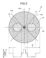
- FIG. 2 is a schematic view illustrating a cross-section of the optical fiber illustrated in FIG. 1 .
- the optical fiber 20 has a core 21 and a cladding 22 that is formed on an outer periphery of the core 21 and includes a pair of stress imparting parts 23 arranged axisymmetrically relative to a symmetrical axis (axis AX2) passing the center of the core 21.
- the optical fiber 20 is a stress imparting type polarization maintaining optical fiber using a birefringence phenomenon due to stress, and the stress imparting parts 23 impart stress to the core 21 so as to maintain a polarization plane.
- the diameter Df of the optical fiber 20 is 125 ⁇ m, for example.
- the polarization plane in a section of the polarization maintaining optical fiber is referred to as a polarization axis.
- the core 21 is formed of silica glass (SiO 2 ) to which a dopant such as germanium (GeO 2 ) increasing a refractive index is added.
- the cladding 22 is formed of pure silica glass in which dopant for adjusting a refractive index is not added, and has a smaller refractive index than the core 21.
- the stress imparting parts 23 are formed of silica glass containing an additive such as boron (B 2 O 3 ).
- B 2 O 3 has a larger thermal expansion ratio than SiO 2 .
- the stress from the stress imparting parts 23 is largest in a direction along an axis AX1 orthogonal to a symmetrical axis of two stress imparting parts 23, and is smallest in a direction along the axis AX2 parallel to the symmetrical axis of two stress imparting parts 23.
- the optical fiber 20 becomes a polarization maintaining optical fiber maintaining polarization of light having polarization along the axis AX1 or the axis AX2. That is, the optical fiber 20 has two polarization axes of the axis AX1 that is the first polarization axis and the axis AX2 that is the second polarization axis.
- the low melting point glass 30 fixes the metal pipe 10 and the optical fiber 20, and hermetically seals the hole 11 to improve the reliability of the semiconductor laser module.
- the fixing material is not limited to low melting point glass. It can be a material the crystal structure of which is an amorphous structure, such as V 2 O 5 , P 2 O 5 , TeO 2 , Fe 2 O 3 , and SiO 2 , or epoxy resin.
- FIG. 3 is a schematic view illustrating a part of a cross-section along line I-I of FIG. 1 .
- the illustration of the metal pipe 10 on the outer periphery is omitted.
- the optical fiber 20 is arranged so that the center of the optical fiber 20 is eccentric to the center of the hole 11. That is, an eccentric distance L that is a distance between the center of the hole 11 and the center of the optical fiber 20 is larger than 0, for example, equal to or larger than a radius of the optical fiber 20.
- the optical fiber 20 is arranged so that an angle ⁇ that is an angle formed by an eccentric direction d connecting the center of the hole 11 and the center of the optical fiber 20 and the axis AX1 is -22.5° or larger but not exceeding 22.5°.
- the influence on the function of maintaining polarization varies with the direction from which stress is applied.
- the stress contributes to the improvement of the function of maintaining polarization of the optical fiber 20.
- the stress contributes to the deterioration of the function of maintaining polarization of the optical fiber 20.
- the angle ⁇ illustrated in FIG. 3 is sufficiently small, and thus the stress S1 contributes to the improvement of the function of maintaining polarization of the optical fiber 20. Furthermore, in the optical fiber fixing structure 1, the eccentric distance L is equal to or larger than a radius of the optical fiber 20, whereby the stress S1 exerts the large effect of improving the function of maintaining polarization of the optical fiber 20. As a result, the deterioration of a polarization extinction ratio is suppressed in the optical fiber fixing structure 1.
- FIG. 4 illustrates an example in which the angle ⁇ is large as a comparative example.
- FIG. 4 is a schematic view illustrating a part of a cross-section along line I-I in an optical fiber fixing structure according to a comparative example.
- stress S2 contributes to the deterioration of the function of maintaining polarization of the optical fiber 20.
- a polarization extinction ratio is deteriorated considerably.
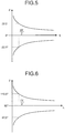
- FIG. 5 and FIG. 6 are diagrams illustrating conditions of an eccentric direction and an eccentric distance with which an extinction ratio variation amount is equal to or smaller than 2 dB.
- the angle ⁇ in FIG. 5 and FIG. 6 is an angle formed by the eccentric direction d and the axis AX1.
- the variation amount of a polarization extinction ratio in the optical fiber fixing structure 1 is equal to or smaller than 2 dB and the deterioration of a polarization extinction ratio is sufficiently small in an area inside curved lines (side close to the axes of the eccentric distance L and the angle ⁇ ).
- FIG. 5 and FIG. 6 are diagrams illustrating conditions of an eccentric direction and an eccentric distance with which an extinction ratio variation amount is equal to or smaller than 2 dB.
- the angle ⁇ in FIG. 5 and FIG. 6 is an angle formed by the eccentric direction d and the axis AX1.
- the variation amount of a polarization extinction ratio in the optical fiber fixing structure 1 is equal to or smaller than 2 dB and the
- the variation amount of the polarization extinction ratio is preferable to be smaller. It is preferable that the extinction ratio variation amount in the optical fiber fixing structure is equal to or smaller than 2 dB because the reliability of a product using the optical fiber fixing structure 1 of the embodiment is secured.
- a total extinction ratio required for an optical module using the optical fiber fixing structure 1 of the embodiment depends on a type of the optical module, and may be equal to or smaller than -25 dB to -13 dB.
- the deterioration of a polarization extinction ratio is substantially same regardless of whether the angle formed by the eccentric direction d and the axis AX1 is equal to or larger than -22.5° but 22.5°, or the angle formed by the eccentric direction d and the axis AX1 is equal to or larger than 67.5° but not exceeding 112.5°, that is, the angle formed by the eccentric direction d and the axis AX2 that is the second polarization axis is equal to or larger than -22.5° but not exceeding 22.5°.
- the angle formed by the eccentric direction d and the axis AX1 is preferably equal to or larger than - 22.5° but 22.5° because the polarization synthesis is easier.
- the suppression of deterioration of a polarization extinction ratio can suppress variation of optical output after polarization synthesis due to bending of the optical fiber 20.
- the deterioration of a polarization extinction ratio is small although the center of the hole 11 is offset from the center of the metal pipe 10.
- fixation of the optical fiber 20 with the low melting point glass 30 can be performed in the state where the center of the optical fiber 20 is offset from the center of the hole 11.
- the conventional optical fiber fixing structure may require a complicated structure to align the center of the hole of the metal pipe and the center of the optical fiber at high accuracy.
- the optical fiber fixing structure 1 provides an optical fiber fixing structure in which the deterioration of a polarization extinction ratio is suppressed without requiring such a complicated structure.
- FIG. 7 is a diagram illustrating an extinction ratio variation amount of optical fiber fixing structures according to examples and comparative examples.
- an extinction ratio variation amount was measured for each of the examples and the comparative examples in which a diameter Dp of the small diameter portion 11a of the hole 11, an eccentric distance L, an eccentricity (2L/Dp), and an angle ⁇ were changed.
- the diameter Dp of the small diameter portion 11a was set to 0.5 mm.
- the thermal expansion coefficient of the metal pipe 10 was set to 9.7 ⁇ 10 -6 /°C
- the thermal expansion coefficient of the optical fiber 20 was set to 0.5 ⁇ 10 -6 /°C
- the thermal expansion coefficient of the low melting point glass 30 was set to 6.0 ⁇ 10 -6 /°C.
- the optical fiber fixing structure 1 is an optical fiber fixing structure in which the deterioration of a polarization extinction ratio is suppressed by setting the angle ⁇ to a certain value.
- FIG. 8 is a schematic sectional side elevation illustrating a structure of a semiconductor laser module using an optical fiber fixing structure according to the embodiment.
- a semiconductor laser module 100 includes a package 101 as a housing containing each unit, a temperature adjusting module 102 as a temperature control device arranged on an inner bottom surface of the package 101, a base 103 arranged on the temperature adjusting module 102, and a laser mount 104 arranged on the base 103.
- a semiconductor laser device 105 as a light emitting element
- a thermistor 106 arranged in the vicinity of the semiconductor laser device 105.
- the optical fiber 20 is arranged on the light path of the laser beam.
- the optical fiber 20 is fixed by an optical fiber fixing pedestal 110 fixed on the base 103 and an optical fiber fixing part 111 fixed to the package 101.
- the optical fiber fixing part 111 has a sectional structure illustrated in FIG. 1 although the illustration of the hole 11 is omitted in the optical fiber fixing part 111.
- the package 101 may be formed of ceramic.
- the temperature adjusting module 102 may be a Peltier element.
- the temperature adjusting module 102 performs cooling and heating with the polarity of a current from a controller not illustrated.
- the temperature adjusting module 102 is controlled based on a value detected by the thermistor 106 to control a temperature of the laser mount 104, thereby adjusting a temperature of the semiconductor laser device 105.
- the semiconductor laser device 105 outputs a laser beam with a certain wavelength.
- the photodetector 107 detects light leaking from the rear side of the semiconductor laser device 105 and inputs electrical signals in accordance with the intensity of the detected light to the controller.
- the lens 108 couples the laser beam output from the semiconductor laser device 105 with the optical fiber 20.
- the isolator 109 prevents the light reflected by other optical parts and the like from returning to the semiconductor laser device 105.
- the isolator 109 may have a structure including a ⁇ /4 plate and a polarizing plate that exclusively transmits light having a polarization plane along a horizontal direction.
- the laser beam output from the semiconductor laser device 105 has a polarization plane along a horizontal direction. In such a case, the polarization plane of the laser beam is rotated relative to a horizontal direction by the ⁇ /4 plate before input to the optical fiber 20.
- the isolator 109 may have a multi-stage structure.
- the optical fiber fixing part 111 includes therein the optical fiber fixing part 1 (not illustrated in FIG. 8 ).
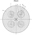
- FIG. 9 is a schematic view illustrating a part of a cross-section along line II-II of FIG. 8 .
- the illustration of the metal pipe 10 on the outer periphery is omitted.
- the polarization plane is rotated by 45° by the ⁇ /4 plate of the isolator 109.
- the optical fiber 20 is arranged so that the polarization axis is 45° relative to a horizontal direction.
- the optical fiber 20 is arranged so that an angle formed by the polarization axis and an eccentric direction connecting the center of the hole 11 and the center of the optical fiber 20 is -22.5° or larger but not exceeding 22.5° and the center of the optical fiber 20 is offset from the center of the hole 11.
- the eccentric direction of the optical fiber 20 may be a direction illustrated by a solid line in FIG. 9 , and may be also directions illustrated by broken lines in FIG. 9 .
- the other structures of the optical fiber fixing structure 1 are same as the embodiment, and thus the explanation thereof is omitted.
- the semiconductor laser module 100 is a semiconductor laser module having a desirable polarization extinction ratio because the optical fiber fixing structure 1 suppresses deterioration of the polarization extinction ratio.
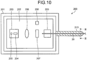
- FIG. 10 is a schematic partial cutout view illustrating a structure of another semiconductor laser module using the optical fiber fixing structure according to the embodiment viewed from the upper side.
- a semiconductor laser module 200 includes a package 201 as a housing containing each unit, a base 202 arranged on an inner bottom surface of the package 201, and a laser mount 203 arranged on the base 202.
- a semiconductor laser device 204 as a light emitting element
- a thermistor 205 arranged in the vicinity of the semiconductor laser device 204.
- the base 202 There are placed, on the base 202, a lens 206 and a beam splitter 207 arranged in this order on an optical path of the laser beam output by the semiconductor laser device 204. A part of the laser beam diverges at the beam splitter 207 and inputs to a photodetector 208. Meanwhile, the optical fiber 20 is arranged on the optical path of the laser beam transmitting the beam splitter 207.
- the optical fiber 20 is fixed by an optical fiber fixing pedestal 209 fixed on the base 202 and an optical fiber fixing part 210 fixed to the package 201. Note that the optical fiber fixing part 210 has a sectional structure illustrated in FIG. 1 although the illustration of the hole 11 is omitted in the optical fiber fixing part 210.
- the package 201 may be formed of ceramic.
- the semiconductor laser device 204 includes a plurality of distributed feedback (DFB) type laser elements with a different oscillation wavelength in a range of about 3 to 4 nm, an optical coupler, and a semiconductor optical amplifier (SOA).
- the semiconductor laser device 204 roughly adjusts a wavelength by selecting a DFB laser element to be driven, finely adjusts the wavelength through temperature change by the temperature adjusting module not illustrated, and operates, as a whole, as a wavelength-tunable light source in a continuous wavelength range.
- DFB distributed feedback
- SOA semiconductor optical amplifier
- the lens 206 couples the laser beam output from the semiconductor laser device 204 with the optical fiber 20.
- the photodetector 208 detects the laser beam diverging at the beam splitter 207 and inputs electrical signals in accordance with the detected strength to the controller not illustrated.
- the optical fiber fixing part 210 has therein the optical fiber fixing structure 1 (not illustrated in FIG. 10 ).
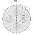
- FIG. 11 is a schematic view illustrating a part of a cross-section along line III-III of FIG. 10 .
- the illustration of the metal pipe 10 on the outer periphery is omitted.
- the laser beam having a polarization plane in a horizontal direction that is output from the semiconductor laser device 204 is input with its polarization as it is to the optical fiber 20.
- the optical fiber 20 is arranged so that any of the polarization axes is along a horizontal direction.
- the optical fiber 20 is arranged so that an angle formed by the polarization axis and the eccentric direction connecting the center of the hole 11 and the center of the optical fiber 20 is -22.5° or larger but not exceeding 22.5° and the center of the optical fiber 20 is offset from the center of the hole 11.
- the eccentric direction of the optical fiber 20 may be a direction illustrated by a solid line in FIG. 11 , and may be also directions illustrated by broken lines in FIG. 11 .
- the other structures of the optical fiber fixing structure 1 are same as the embodiment, and thus the explanation thereof is omitted.
- the semiconductor laser module 200 is a semiconductor laser module having a desirable polarization extinction ratio because the optical fiber fixing structure 1 suppresses deterioration of the polarization extinction ratio.
- the optical fiber 20 is a polarization maintaining optical fiber having two polarization planes, but the optical fiber 20 may be a single polarization optical fiber having one polarization plane. In the latter case, it is only necessary that the angle formed by the eccentric direction d and the polarization plane is -22.5° or larger but not exceeding 22.5°, or 67.5° or larger but not exceeding 112.5°.
- the optical fiber fixing structure according to the invention is preferably applied to a semiconductor laser module.
Landscapes
- Physics & Mathematics (AREA)
- General Physics & Mathematics (AREA)
- Optics & Photonics (AREA)
- Nonlinear Science (AREA)
- Optical Couplings Of Light Guides (AREA)
- Optical Fibers, Optical Fiber Cores, And Optical Fiber Bundles (AREA)
Abstract
Description
- The present invention relates to an optical fiber fixing structure.
- A semiconductor laser module outputting light from an optical fiber has an optical fiber fixing structure in which the optical fiber is inserted into and fixed to a metal pipe fixed to a semiconductor laser module package. The metal pipe and the optical fiber are fixed with an adhesive such as low melting point glass and hermetically sealed. Here, the thermal expansion coefficients of the metal pipe and the low melting point glass are larger than that of the optical fiber. Thus, stress is applied on the optical fiber.
- Moreover, there is disclosed a polarization maintaining optical fiber that propagates light while maintaining the polarization plane of the light. The polarization maintaining optical fiber has a core and a cladding that is formed on the outer periphery of the core and includes a pair of stress imparting parts arranged in lateral regions to the core. In this polarization maintaining optical fiber, the stress imparting parts impart stress to the core, and a birefringence phenomenon due to stress is used to maintain a polarization plane. In such a stress imparting type polarization maintaining optical fiber, when stress is applied from the outside, stress imparted to the core is changed, which may deteriorate a polarization extinction ratio.
- That is, the optical fiber fixing structure of a semiconductor laser module using a polarization maintaining optical fiber has a problem in that stress is applied on the optical fiber and a polarization extinction ratio is deteriorated. Then, there are disclosed structures that reduce stress applied to the polarization maintaining optical fiber from the outside and suppress deterioration of a polarization extinction ratio (see
Patent Literatures 1 to 3, for example). -
- Patent Literature 1: Japanese Laid-open Patent Publication No.
62-299918 - Patent Literature 2: Japanese Laid-open Patent Publication No.
2007-264346 - Patent Literature 3: Japanese Laid-open Patent Publication No.
6-67038 - However, birefringence is considerably sensitive to stress, and there has been a problem in that a polarization extinction ratio is deteriorated when the polarization maintaining optical fiber deviates from the center of a hole of a metal pipe.
- In view of the above-described aspect, the present invention aims at providing an optical fiber fixing structure in which the deterioration of a polarization extinction ratio is suppressed.
- To solve the above-described problem and achieve the object, an optical fiber fixing structure according to one aspect of the present invention includes: a cylindrical member; an optical fiber inserted into a hole of the cylindrical member; and a fixing material configured to fix the cylindrical member and the optical fiber, wherein the optical fiber is a polarization maintaining optical fiber having a polarization axis, and a center of the optical fiber is arranged so as to be eccentric to a center of the hole, and an angle formed by an eccentric direction connecting the center of the hole and the center of the optical fiber and the polarization axis is -22.5° to 22.5°, or 67.5° to 112.5°.
- Moreover, in the optical fiber fixing structure according to one aspect of the present invention, the optical fiber includes: a core; and a cladding that includes a pair of stress imparting parts arranged axisymmetrically relative to a symmetrical axis passing a center of the core, the polarization axis includes a first polarization axis, and a second polarization axis orthogonal to the first polarization axis, the first polarization axis is an axis in a direction orthogonal to the symmetrical axis, and the second polarization axis is an axis in a direction parallel to the symmetrical axis.
- Moreover, in the optical fiber fixing structure according to one aspect of the present invention, a distance between the center of the hole and the center of the optical fiber is equal to or larger than a radius of the optical fiber.
- Moreover, in the optical fiber fixing structure according to one aspect of the present invention, the hole of the cylindrical member includes: a small diameter portion with a diameter of the hole that is constant and smaller than other parts; and a diameter enlarged portion that is arranged on both sides of the small diameter portion and gradually becomes larger in diameter of the hole along a direction away from the small diameter portion, and the fixing material fixes the cylindrical member and the optical fiber at the small diameter portion.
- Moreover, in the optical fiber fixing structure according to one aspect of the present invention, the fixing material is a material a crystal structure of which is an amorphous structure.
- Moreover, in the optical fiber fixing structure according to one aspect of the present invention, the fixing material is configured to hermetically seal the hole.
- Moreover, in the optical fiber fixing structure according to one aspect of the present invention, a diameter of a part with a smallest diameter of the hole in a fixing part of the cylindrical member and the optical fiber is equal to or larger than twice but not exceeding eight times of a diameter of the optical fiber.
- Moreover, in the optical fiber fixing structure according to one aspect of the present invention, a thermal expansion coefficient of the cylindrical member is larger than a thermal expansion coefficient of the fixing material. Advantageous Effects of Invention
- The invention can provide an optical fiber fixing structure in which the deterioration of a polarization extinction ratio is suppressed.
-
-
FIG. 1 is a schematic view illustrating a section of an optical fiber fixing structure according to an embodiment of the invention. -
FIG. 2 is a schematic view illustrating a cross-section of an optical fiber illustrated inFIG. 1 . -
FIG. 3 is a schematic view illustrating a part of a cross-section along line I-I ofFIG. 1 . -
FIG. 4 is a schematic view illustrating a part of a cross-section along line I-I in an optical fiber fixing structure according to a comparative example. -
FIG. 5 is a diagram illustrating conditions of an eccentric direction and an eccentric distance with which an extinction ratio variation amount is equal to or smaller than 2 dB. -
FIG. 6 is a diagram illustrating conditions of an eccentric direction and an eccentric distance with which an extinction ratio variation amount is equal to or smaller than 2 dB. -
FIG. 7 is a diagram illustrating extinction ratio variation amounts of optical fiber fixing structures according to examples and comparative examples. -
FIG. 8 is a schematic sectional side elevation illustrating a structure of a semiconductor laser module using the optical fiber fixing structure according to the embodiment. -
FIG. 9 is a schematic view illustrating a part of a cross-section along line II-II ofFIG. 8 . -
FIG. 10 is a schematic partial cutout view illustrating a structure of another semiconductor laser module using the optical fiber fixing structure according to the embodiment viewed from the upper side. -
FIG. 11 is a schematic view illustrating a part of a cross-section along line III-III ofFIG. 10 . - The following will describe an embodiment of an optical fiber fixing structure according to the invention with reference to the enclosed drawings. Note that the embodiment does not limit the invention. In the drawings, the same or corresponding elements are appropriately represented with the same symbols. The drawings are illustrated schematically, and it should be noted that the size relation of the elements, the proportion of the elements, and the like may be different from actual implementations. Also among drawings, parts mutually different in size relation or proportion may be included.
- An optical fiber fixing structure according to an embodiment of the invention will be described first.
FIG. 1 is a schematic view illustrating a section of an optical fiber fixing structure according to an embodiment of the invention. As illustrated inFIG. 1 , an opticalfiber fixing structure 1 includes ametal pipe 10 as a cylindrical member, anoptical fiber 20 inserted into ahole 11 of themetal pipe 10, and lowmelting point glass 30 as a fixing material that fixes themetal pipe 10 and theoptical fiber 20. Note thatFIG. 1 is an enlarged view of the opticalfiber fixing structure 1, and omits the illustration of the upper and the lower sides and the right side of themetal pipe 10. - Here, the low
melting point glass 30 indicates glass that softens at 600°C or lower. - A thermal expansion coefficient of the
metal pipe 10 is larger than a thermal expansion coefficient of the lowmelting point glass 30. The thermal expansion coefficient of the lowmelting point glass 30 is larger than a thermal expansion coefficient of theoptical fiber 20. Thus, themetal pipe 10 and the lowmelting point glass 30 apply stress on theoptical fiber 20 to caulk it, so that theoptical fiber 20 is fixed to themetal pipe 10 and thehole 11 is hermetically sealed. - Here, hermetically sealing indicates the state in which the package inner space is in an inert gas atmosphere such as N2 and the inert gas does not leak at a temperature of -20°C to 75°C.
- The
metal pipe 10 has thehole 11 extending in a longitudinal direction. Thehole 11 has asmall diameter portion 11a at which a diameter of thehole 11 is constant and smaller than the other parts, and has, on both sides of thesmall diameter portion 11a, diameter enlargedportions hole 11 gradually enlarges along a direction away from thesmall diameter portion 11a. Moreover, thehole 11 includesparallel portions portions FIG. 1 , thesmall diameter portion 11a is a part with the smallest diameter in thehole 11 in the part where themetal pipe 10 and theoptical fiber 20 are fixed. A diameter Dp of thesmall diameter portion 11a is preferably twice or larger than a diameter Df of theoptical fiber 20 but not exceeding eight times of the diameter Df. For example, when the diameter Df of theoptical fiber 20 is 125 µm, the diameter Dp of thesmall diameter portion 11a is preferably 250 µm or larger but not exceeding 1000 µm. This is because with an excessivelysmall diameter portion 11a, stress applied on theoptical fiber 20 from themetal pipe 10 and the lowmelting point glass 30 becomes excessively large, which leads to the deterioration of a polarization extinction ratio. Moreover, when thesmall diameter portion 11a is excessively large, it becomes difficult to form the lowmelting point glass 30 at a desired position in manufacturing. The length of thesmall diameter portion 11a is preferably 0.5 mm or larger, for example. It is because with an excessively short small diameter portion, thehole 11 cannot be hermetically sealed sufficiently. Note that the cylindrical member may be formed of a material other than metal, and the material is not especially limited. The diameter enlargedportions small diameter portion 11a facilitate the formation of the lowmelting point glass 30 at a desired position in manufacturing, and thus thehole 11 can be hermetically sealed easily. - The
optical fiber 20 is a polarization maintaining optical fiber having a polarization plane.FIG. 2 is a schematic view illustrating a cross-section of the optical fiber illustrated inFIG. 1 . As illustrated inFIG. 2 , theoptical fiber 20 has acore 21 and acladding 22 that is formed on an outer periphery of thecore 21 and includes a pair ofstress imparting parts 23 arranged axisymmetrically relative to a symmetrical axis (axis AX2) passing the center of thecore 21. Theoptical fiber 20 is a stress imparting type polarization maintaining optical fiber using a birefringence phenomenon due to stress, and thestress imparting parts 23 impart stress to the core 21 so as to maintain a polarization plane. The diameter Df of theoptical fiber 20 is 125 µm, for example. - Note that in the specification, the polarization plane in a section of the polarization maintaining optical fiber is referred to as a polarization axis.
- The
core 21 is formed of silica glass (SiO2) to which a dopant such as germanium (GeO2) increasing a refractive index is added. Thecladding 22 is formed of pure silica glass in which dopant for adjusting a refractive index is not added, and has a smaller refractive index than thecore 21. - The
stress imparting parts 23 are formed of silica glass containing an additive such as boron (B2O3). B2O3 has a larger thermal expansion ratio than SiO2. Thus, when the optical fiber is cooled and solidified in drawing of a glass preform including thestress imparting parts 23 by heating and melting it at a high temperature, thestress imparting parts 23 imparts stress to thecore 21. Such stress causes birefringence at thecore 21, whereby polarization maintaining characteristics are obtained. - The stress from the
stress imparting parts 23 is largest in a direction along an axis AX1 orthogonal to a symmetrical axis of twostress imparting parts 23, and is smallest in a direction along the axis AX2 parallel to the symmetrical axis of twostress imparting parts 23. As a result, birefringence occurs, and theoptical fiber 20 becomes a polarization maintaining optical fiber maintaining polarization of light having polarization along the axis AX1 or the axis AX2. That is, theoptical fiber 20 has two polarization axes of the axis AX1 that is the first polarization axis and the axis AX2 that is the second polarization axis. - The low
melting point glass 30 fixes themetal pipe 10 and theoptical fiber 20, and hermetically seals thehole 11 to improve the reliability of the semiconductor laser module. The fixing material is not limited to low melting point glass. It can be a material the crystal structure of which is an amorphous structure, such as V2O5, P2O5, TeO2, Fe2O3, and SiO2, or epoxy resin. -
FIG. 3 is a schematic view illustrating a part of a cross-section along line I-I ofFIG. 1 . InFIG. 3 , the illustration of themetal pipe 10 on the outer periphery is omitted. As illustrated inFIG. 3 , in the opticalfiber fixing structure 1, theoptical fiber 20 is arranged so that the center of theoptical fiber 20 is eccentric to the center of thehole 11. That is, an eccentric distance L that is a distance between the center of thehole 11 and the center of theoptical fiber 20 is larger than 0, for example, equal to or larger than a radius of theoptical fiber 20. Moreover, in the opticalfiber fixing structure 1, theoptical fiber 20 is arranged so that an angle θ that is an angle formed by an eccentric direction d connecting the center of thehole 11 and the center of theoptical fiber 20 and the axis AX1 is -22.5° or larger but not exceeding 22.5°. - The following will describe the effect of the optical
fiber fixing structure 1. As illustrated inFIG. 3 , stress from themetal pipe 10 and the lowmelting point glass 30 is not isotropic when the center of theoptical fiber 20 is eccentric to the center of thehole 11. Thus, stress S1 substantially along the eccentric direction d is applied on theoptical fiber 20. - Here, when stress is applied on the
optical fiber 20 from the outside, the influence on the function of maintaining polarization varies with the direction from which stress is applied. For example, when stress is applied on theoptical fiber 20 from a direction along the axis AX1 or the axis AX2 that is a polarization axis illustrated inFIG. 2 , the stress contributes to the improvement of the function of maintaining polarization of theoptical fiber 20. Meanwhile, when stress is applied on theoptical fiber 20 from a direction along the axis AX3 or the axis AX4 in a direction inclined 45° to the polarization axis, the stress contributes to the deterioration of the function of maintaining polarization of theoptical fiber 20. - In the optical
fiber fixing structure 1, the angle θ illustrated inFIG. 3 is sufficiently small, and thus the stress S1 contributes to the improvement of the function of maintaining polarization of theoptical fiber 20. Furthermore, in the opticalfiber fixing structure 1, the eccentric distance L is equal to or larger than a radius of theoptical fiber 20, whereby the stress S1 exerts the large effect of improving the function of maintaining polarization of theoptical fiber 20. As a result, the deterioration of a polarization extinction ratio is suppressed in the opticalfiber fixing structure 1. - By contrast,
FIG. 4 illustrates an example in which the angle θ is large as a comparative example.FIG. 4 is a schematic view illustrating a part of a cross-section along line I-I in an optical fiber fixing structure according to a comparative example. When the angle θ is large as illustrated inFIG. 4 , stress S2 contributes to the deterioration of the function of maintaining polarization of theoptical fiber 20. Thus, in the optical fiber fixing structure of the comparative example, a polarization extinction ratio is deteriorated considerably. - Here, it was confirmed by the experiment how small the angle θ is to sufficiently reduce a polarization extinction ratio in the optical
fiber fixing structure 1.FIG. 5 and FIG. 6 are diagrams illustrating conditions of an eccentric direction and an eccentric distance with which an extinction ratio variation amount is equal to or smaller than 2 dB. The angle θ inFIG. 5 and FIG. 6 is an angle formed by the eccentric direction d and the axis AX1. InFIG. 5 and FIG. 6 , the variation amount of a polarization extinction ratio in the opticalfiber fixing structure 1 is equal to or smaller than 2 dB and the deterioration of a polarization extinction ratio is sufficiently small in an area inside curved lines (side close to the axes of the eccentric distance L and the angle θ). InFIG. 5 , the deterioration of a polarization extinction ratio is small although the eccentric distance L is large to a certain extent as long as the angle θ is -22.5° or larger but not exceeding 22.5°. By contrast, in a range where the angle θ is smaller than -22.5° or larger than 22.5°, the polarization extinction ratio is deteriorated drastically as the eccentric distance L is larger, and exceeds 2 dB. InFIG. 6 , when the angle θ is equal to or 67.5° but not exceeding 112.5°, that is, the angle formed by the eccentric direction d and the axis AX2 that is the second polarization axis is equal to or larger than -22.5° but not exceeding 22.5°, the deterioration of the polarization extinction ratio is small although the eccentric distance L is large to a certain extent. By contrast, in a range where the angle θ is smaller than 67.5° or larger than 112.5°, the polarization extinction ratio is deteriorated drastically as the eccentric distance L is larger, and exceeds 2 dB. In other words, the deterioration of a polarization extinction ratio is sufficiently small when the angle formed by the eccentric direction d and one of two polarization axes of theoptical fiber 20 is equal to or larger than -22.5° but not exceeding 22.5°. - Note that the variation amount of the polarization extinction ratio is preferable to be smaller. It is preferable that the extinction ratio variation amount in the optical fiber fixing structure is equal to or smaller than 2 dB because the reliability of a product using the optical
fiber fixing structure 1 of the embodiment is secured. - A total extinction ratio required for an optical module using the optical
fiber fixing structure 1 of the embodiment depends on a type of the optical module, and may be equal to or smaller than -25 dB to -13 dB. - Moreover, as illustrated in
FIG. 5 and FIG. 6 , the deterioration of a polarization extinction ratio is substantially same regardless of whether the angle formed by the eccentric direction d and the axis AX1 is equal to or larger than -22.5° but 22.5°, or the angle formed by the eccentric direction d and the axis AX1 is equal to or larger than 67.5° but not exceeding 112.5°, that is, the angle formed by the eccentric direction d and the axis AX2 that is the second polarization axis is equal to or larger than -22.5° but not exceeding 22.5°. However, when polarization synthesis is performed in an optical module using the opticalfiber fixing structure 1 of the embodiment, the angle formed by the eccentric direction d and the axis AX1 is preferably equal to or larger than - 22.5° but 22.5° because the polarization synthesis is easier. The suppression of deterioration of a polarization extinction ratio can suppress variation of optical output after polarization synthesis due to bending of theoptical fiber 20. - As seen from
FIG. 5 and FIG. 6 , in the opticalfiber fixing structure 1, the deterioration of a polarization extinction ratio is small although the center of thehole 11 is offset from the center of themetal pipe 10. Thus, fixation of theoptical fiber 20 with the lowmelting point glass 30 can be performed in the state where the center of theoptical fiber 20 is offset from the center of thehole 11. By contrast, in the conventional optical fiber fixing structure, it is necessary to fix the optical fiber with the low melting point glass in the state where the center of the hole of the metal pipe and the center of the optical fiber are aligned at high accuracy, and the polarization extinction ratio may be deteriorated unless the alignment is sufficiently accurate. - Moreover, the conventional optical fiber fixing structure may require a complicated structure to align the center of the hole of the metal pipe and the center of the optical fiber at high accuracy. By contrast, the optical
fiber fixing structure 1 provides an optical fiber fixing structure in which the deterioration of a polarization extinction ratio is suppressed without requiring such a complicated structure. - Next, as examples and comparative examples, optical fiber fixing structures were produced actually to measure a variation amount of a polarization extinction ratio in the optical fiber fixing structures.
FIG. 7 is a diagram illustrating an extinction ratio variation amount of optical fiber fixing structures according to examples and comparative examples. As illustrated inFIG. 7 , an extinction ratio variation amount was measured for each of the examples and the comparative examples in which a diameter Dp of thesmall diameter portion 11a of thehole 11, an eccentric distance L, an eccentricity (2L/Dp), and an angle θ were changed. As illustrated inFIG. 7 , the diameter Dp of thesmall diameter portion 11a was set to 0.5 mm. The thermal expansion coefficient of themetal pipe 10 was set to 9.7 × 10⁻⁶/°C, the thermal expansion coefficient of theoptical fiber 20 was set to 0.5 × 10⁻⁶/°C, and the thermal expansion coefficient of the lowmelting point glass 30 was set to 6.0 × 10⁻⁶/°C. - As seen from
FIG. 7 , the deterioration of a polarization extinction ratio is sufficiently small in Examples 1 to 3, while a polarization extinction ratio is considerably deteriorated in Comparative Example 1 and Comparative Example 2. This is because in Comparative Example 1 and Comparative Example 2, the angle θ is large and the stress contributes to the deterioration of the function of maintaining polarization of theoptical fiber 20. By contrast, in Examples 1 to 3 in which the angle θ is in a range equal to or larger than -22.5° but not exceeding 22.5°, the stress contributes to the improvement of the function of maintaining polarization of theoptical fiber 20, and thus the deterioration of the polarization extinction ratio is small. Moreover, in Examples and Comparative Examples, the eccentric distance L and the eccentricity (2L/Dp) are also changed, but it is recognized that the deterioration of a polarization extinction ratio largely depends on the change of the angle θ, and other parameters do not considerably contribute to deterioration of a polarization extinction ratio. As disclosed in the preceding description, the opticalfiber fixing structure 1 is an optical fiber fixing structure in which the deterioration of a polarization extinction ratio is suppressed by setting the angle θ to a certain value. - The following will describe a semiconductor laser module using the optical
fiber fixing structure 1 according to the embodiment of the invention.FIG. 8 is a schematic sectional side elevation illustrating a structure of a semiconductor laser module using an optical fiber fixing structure according to the embodiment. As illustrated inFIG. 8 , asemiconductor laser module 100 includes apackage 101 as a housing containing each unit, atemperature adjusting module 102 as a temperature control device arranged on an inner bottom surface of thepackage 101, a base 103 arranged on thetemperature adjusting module 102, and alaser mount 104 arranged on thebase 103. There are placed, on thelaser mount 104, asemiconductor laser device 105 as a light emitting element, and athermistor 106 arranged in the vicinity of thesemiconductor laser device 105. There are placed, on thebase 103, aphotodetector 107 arranged on the side behind thesemiconductor laser device 105, and alens 108 and anisolator 109 arranged in this order on an optical path of a laser beam output by thesemiconductor laser device 105. Furthermore, theoptical fiber 20 is arranged on the light path of the laser beam. Theoptical fiber 20 is fixed by an opticalfiber fixing pedestal 110 fixed on thebase 103 and an opticalfiber fixing part 111 fixed to thepackage 101. Note that the opticalfiber fixing part 111 has a sectional structure illustrated inFIG. 1 although the illustration of thehole 11 is omitted in the opticalfiber fixing part 111. - The
package 101 may be formed of ceramic. Thetemperature adjusting module 102 may be a Peltier element. Thetemperature adjusting module 102 performs cooling and heating with the polarity of a current from a controller not illustrated. Thetemperature adjusting module 102 is controlled based on a value detected by thethermistor 106 to control a temperature of thelaser mount 104, thereby adjusting a temperature of thesemiconductor laser device 105. Thesemiconductor laser device 105 outputs a laser beam with a certain wavelength. - The
photodetector 107 detects light leaking from the rear side of thesemiconductor laser device 105 and inputs electrical signals in accordance with the intensity of the detected light to the controller. Thelens 108 couples the laser beam output from thesemiconductor laser device 105 with theoptical fiber 20. - The
isolator 109 prevents the light reflected by other optical parts and the like from returning to thesemiconductor laser device 105. Theisolator 109 may have a structure including a λ/4 plate and a polarizing plate that exclusively transmits light having a polarization plane along a horizontal direction. The laser beam output from thesemiconductor laser device 105 has a polarization plane along a horizontal direction. In such a case, the polarization plane of the laser beam is rotated relative to a horizontal direction by the λ/4 plate before input to theoptical fiber 20. Note that theisolator 109 may have a multi-stage structure. - The optical
fiber fixing part 111 includes therein the optical fiber fixing part 1 (not illustrated inFIG. 8 ).FIG. 9 is a schematic view illustrating a part of a cross-section along line II-II ofFIG. 8 . InFIG. 9 , the illustration of themetal pipe 10 on the outer periphery is omitted. Regarding the laser beam having a polarization plane along a horizontal direction that is output from thesemiconductor laser device 105, the polarization plane is rotated by 45° by the λ/4 plate of theisolator 109. Thus, theoptical fiber 20 is arranged so that the polarization axis is 45° relative to a horizontal direction. Then, theoptical fiber 20 is arranged so that an angle formed by the polarization axis and an eccentric direction connecting the center of thehole 11 and the center of theoptical fiber 20 is -22.5° or larger but not exceeding 22.5° and the center of theoptical fiber 20 is offset from the center of thehole 11. The eccentric direction of theoptical fiber 20 may be a direction illustrated by a solid line inFIG. 9 , and may be also directions illustrated by broken lines inFIG. 9 . The other structures of the opticalfiber fixing structure 1 are same as the embodiment, and thus the explanation thereof is omitted. - As described above, the
semiconductor laser module 100 is a semiconductor laser module having a desirable polarization extinction ratio because the opticalfiber fixing structure 1 suppresses deterioration of the polarization extinction ratio. - The following will describe another semiconductor laser module using the optical
fiber fixing structure 1 according to the embodiment of the invention.FIG. 10 is a schematic partial cutout view illustrating a structure of another semiconductor laser module using the optical fiber fixing structure according to the embodiment viewed from the upper side. As illustrated inFIG. 10 , asemiconductor laser module 200 includes apackage 201 as a housing containing each unit, a base 202 arranged on an inner bottom surface of thepackage 201, and alaser mount 203 arranged on thebase 202. There are placed, on thelaser mount 203, asemiconductor laser device 204 as a light emitting element, and athermistor 205 arranged in the vicinity of thesemiconductor laser device 204. There are placed, on thebase 202, alens 206 and abeam splitter 207 arranged in this order on an optical path of the laser beam output by thesemiconductor laser device 204. A part of the laser beam diverges at thebeam splitter 207 and inputs to aphotodetector 208. Meanwhile, theoptical fiber 20 is arranged on the optical path of the laser beam transmitting thebeam splitter 207. Theoptical fiber 20 is fixed by an opticalfiber fixing pedestal 209 fixed on thebase 202 and an opticalfiber fixing part 210 fixed to thepackage 201. Note that the opticalfiber fixing part 210 has a sectional structure illustrated inFIG. 1 although the illustration of thehole 11 is omitted in the opticalfiber fixing part 210. - The
package 201 may be formed of ceramic. Thesemiconductor laser device 204 includes a plurality of distributed feedback (DFB) type laser elements with a different oscillation wavelength in a range of about 3 to 4 nm, an optical coupler, and a semiconductor optical amplifier (SOA). Thesemiconductor laser device 204 roughly adjusts a wavelength by selecting a DFB laser element to be driven, finely adjusts the wavelength through temperature change by the temperature adjusting module not illustrated, and operates, as a whole, as a wavelength-tunable light source in a continuous wavelength range. - The
lens 206 couples the laser beam output from thesemiconductor laser device 204 with theoptical fiber 20. Thephotodetector 208 detects the laser beam diverging at thebeam splitter 207 and inputs electrical signals in accordance with the detected strength to the controller not illustrated. - The optical
fiber fixing part 210 has therein the optical fiber fixing structure 1 (not illustrated inFIG. 10 ).FIG. 11 is a schematic view illustrating a part of a cross-section along line III-III ofFIG. 10 . InFIG. 11 , the illustration of themetal pipe 10 on the outer periphery is omitted. The laser beam having a polarization plane in a horizontal direction that is output from thesemiconductor laser device 204 is input with its polarization as it is to theoptical fiber 20. Thus, theoptical fiber 20 is arranged so that any of the polarization axes is along a horizontal direction. Then, theoptical fiber 20 is arranged so that an angle formed by the polarization axis and the eccentric direction connecting the center of thehole 11 and the center of theoptical fiber 20 is -22.5° or larger but not exceeding 22.5° and the center of theoptical fiber 20 is offset from the center of thehole 11. For example, the eccentric direction of theoptical fiber 20 may be a direction illustrated by a solid line inFIG. 11 , and may be also directions illustrated by broken lines inFIG. 11 . The other structures of the opticalfiber fixing structure 1 are same as the embodiment, and thus the explanation thereof is omitted. - As described above, the
semiconductor laser module 200 is a semiconductor laser module having a desirable polarization extinction ratio because the opticalfiber fixing structure 1 suppresses deterioration of the polarization extinction ratio. - Note that the above-described embodiment describes the case in which the
optical fiber 20 is a polarization maintaining optical fiber having two polarization planes, but theoptical fiber 20 may be a single polarization optical fiber having one polarization plane. In the latter case, it is only necessary that the angle formed by the eccentric direction d and the polarization plane is -22.5° or larger but not exceeding 22.5°, or 67.5° or larger but not exceeding 112.5°. - The above-described embodiment does not limit the invention. The invention includes embodiments formed by appropriately combining the above-described components. Moreover, further effects and modifications can be derived easily by a person skilled in the art. Therefore, a wider range of forms of the invention is not limited to the above-described embodiment, and various changes can be made.
- As described above, for example, the optical fiber fixing structure according to the invention is preferably applied to a semiconductor laser module. Reference Signs List
-
- 1 optical fiber fixing structure
- 10 metal pipe
- 11 hole
- 11a small diameter portion
- 11b, 11c diameter enlarged portion
- 11d, 11e parallel portion
- 20 optical fiber
- 21 core
- 22 cladding
- 23 stress imparting part
- 30 low melting point glass
- 100, 200 semiconductor laser module
- 101, 201 package
- 102 temperature adjusting module
- 103, 202 base
- 104, 203 laser mount
- 105, 204 semiconductor laser device
- 106, 205 thermistor
- 107, 208 photodetector
- 108, 206 lens
- 109 isolator
- 110, 209 optical fiber fixing pedestal
- 111, 210 optical fiber fixing part
- 207 beam splitter
- AX1, AX2, AX3, AX4 axis
- d eccentric direction
- Df, Dp diameter
- L eccentric distance
- S1, S2 stress
- θ angle
Claims (8)
- An optical fiber fixing structure comprising:a cylindrical member;an optical fiber inserted into a hole of the cylindrical member; anda fixing material configured to fix the cylindrical member and the optical fiber, whereinthe optical fiber is a polarization maintaining optical fiber having a polarization axis, anda center of the optical fiber is arranged so as to be eccentric to a center of the hole, andan angle formed by an eccentric direction connecting the center of the hole and the center of the optical fiber and the polarization axis is -22.5° to 22.5°, or 67.5° to 112.5°.
- The optical fiber fixing structure according to claim 1, wherein
the optical fiber includes:a core; anda cladding that includes a pair of stress imparting parts arranged axisymmetrically relative to a symmetrical axis passing a center of the core,the polarization axis includes a first polarization axis, and a second polarization axis orthogonal to the first polarization axis,
the first polarization axis is an axis in a direction orthogonal to the symmetrical axis, and
the second polarization axis is an axis in a direction parallel to the symmetrical axis. - The optical fiber fixing structure according to claim 1 or 2, wherein a distance between the center of the hole and the center of the optical fiber is equal to or larger than a radius of the optical fiber.
- The optical fiber fixing structure according to any one of claims 1 to 3, wherein
the hole of the cylindrical member includes:a small diameter portion with a diameter of the hole that is constant and smaller than other parts; anda diameter enlarged portion that is arranged on both sides of the small diameter portion and gradually becomes larger in diameter of the hole along a direction away from the small diameter portion, andthe fixing material fixes the cylindrical member and the optical fiber at the small diameter portion. - The optical fiber fixing structure according to any one of claims 1 to 4, wherein the fixing material is a material a crystal structure of which is an amorphous structure.
- The optical fiber fixing structure according to any one of claims 1 to 5, wherein the fixing material is configured to hermetically seal the hole.
- The optical fiber fixing structure according to any one of claims 1 to 6, wherein a diameter of a part with a smallest diameter of the hole in a fixing part of the cylindrical member and the optical fiber is equal to or larger than twice but not exceeding eight times of a diameter of the optical fiber.
- The optical fiber fixing structure according to any one of claims 1 to 7, wherein a thermal expansion coefficient of the cylindrical member is larger than a thermal expansion coefficient of the fixing material.
Applications Claiming Priority (2)
| Application Number | Priority Date | Filing Date | Title |
|---|---|---|---|
| JP2015026930 | 2015-02-13 | ||
| PCT/JP2016/053411 WO2016129505A1 (en) | 2015-02-13 | 2016-02-04 | Optical-fiber affixing structure |
Publications (2)
| Publication Number | Publication Date |
|---|---|
| EP3258299A1 true EP3258299A1 (en) | 2017-12-20 |
| EP3258299A4 EP3258299A4 (en) | 2018-08-15 |
Family
ID=56614582
Family Applications (1)
| Application Number | Title | Priority Date | Filing Date |
|---|---|---|---|
| EP16749149.7A Withdrawn EP3258299A4 (en) | 2015-02-13 | 2016-02-04 | Optical-fiber affixing structure |
Country Status (5)
| Country | Link |
|---|---|
| US (1) | US10551576B2 (en) |
| EP (1) | EP3258299A4 (en) |
| JP (1) | JP6928451B2 (en) |
| CN (1) | CN106796327B (en) |
| WO (1) | WO2016129505A1 (en) |
Families Citing this family (4)
| Publication number | Priority date | Publication date | Assignee | Title |
|---|---|---|---|---|
| JP6935206B2 (en) * | 2017-02-14 | 2021-09-15 | 古河電気工業株式会社 | Optical element package and optical element module |
| CN110346889B (en) * | 2019-08-12 | 2024-04-05 | 中国工程物理研究院激光聚变研究中心 | Optical fiber clamp and optical fiber debugging equipment |
| WO2022026269A1 (en) * | 2020-07-31 | 2022-02-03 | Corning Incorporated | An optical system comprising a polarization controller and a method of operation |
| CN117317793A (en) * | 2023-11-27 | 2023-12-29 | 珠海天启技术有限公司 | An optical fiber fixing structure for fiber output lasers |
Family Cites Families (32)
| Publication number | Priority date | Publication date | Assignee | Title |
|---|---|---|---|---|
| US49983A (en) * | 1865-09-19 | Improved lubricating compound for journal-boxes | ||
| JPS62100711A (en) * | 1985-10-28 | 1987-05-11 | Nippon Telegr & Teleph Corp <Ntt> | Fixing jig for optical fiber |
| JPH0750216B2 (en) | 1986-06-20 | 1995-05-31 | 日本電信電話株式会社 | Polarization-maintaining optical fiber fixing method |
| JPH0616126B2 (en) * | 1986-11-06 | 1994-03-02 | 日本電気株式会社 | Ferrule for optical fiber connection |
| JPH0264508A (en) * | 1988-08-31 | 1990-03-05 | Fujitsu Ltd | Ferrule for fixing constant polarization optical fiber and method for fixing constant polarization optical fiber by using said ferrule |
| US5127072A (en) * | 1990-03-08 | 1992-06-30 | Ortel Corporation | Laser module with compliant optical fiber coupling |
| GB9007019D0 (en) * | 1990-03-29 | 1990-05-30 | British Telecomm | Optical fibre feedthrough |
| JP2845043B2 (en) * | 1992-08-21 | 1999-01-13 | 日本電気株式会社 | Hermetically sealed structure of optical fiber introduction section |
| JP2996602B2 (en) * | 1995-01-31 | 2000-01-11 | 株式会社精工技研 | Optical branching coupler for constant polarization optical fiber |
| US5633970A (en) * | 1995-05-23 | 1997-05-27 | Minnesota Mining And Manufacturing Company | Device with internal asymmetrical features for rotational alignment of non-symmetrical articles |
| US5812258A (en) * | 1995-11-20 | 1998-09-22 | Sentech Systems, Inc. | Optical coupler and alignment apparatus with multiple eccentric adjustments |
| JPH1138276A (en) * | 1997-07-22 | 1999-02-12 | Seiko Giken:Kk | Optical connector structure and alignment method |
| JP3884857B2 (en) * | 1998-03-12 | 2007-02-21 | 富士通株式会社 | Polarization synthesizer and polarization separator |
| JP2002040291A (en) * | 2000-05-17 | 2002-02-06 | Furukawa Electric Co Ltd:The | Manufacturing method of ferruled fiber and ferruled fiber |
| US6920255B2 (en) * | 2000-08-31 | 2005-07-19 | Corning Incorporated | Polarizer-equipped optical fiber ferrule, connector and connector adaptor |
| SE522957C2 (en) * | 2000-09-11 | 2004-03-16 | Ericsson Telefon Ab L M | A device for providing polarized light |
| JP3904398B2 (en) * | 2001-03-14 | 2007-04-11 | 東京特殊電線株式会社 | Manufacturing method of multi-core polarization maintaining fiber assembly |
| JP2002296438A (en) * | 2001-03-29 | 2002-10-09 | Fujikura Ltd | Polarization-maintaining optical fiber and method of manufacturing base material thereof |
| JP4398598B2 (en) * | 2001-04-02 | 2010-01-13 | 古河電気工業株式会社 | Polarization-maintaining fiber, manufacturing method thereof, and semiconductor laser module |
| WO2002079840A1 (en) * | 2001-04-02 | 2002-10-10 | Tyco Electronics Corpporation | Optical fiber assembly with adjustable fiber radial orientation |
| JP2003014988A (en) * | 2001-06-28 | 2003-01-15 | Ykk Corp | Optical connector and ferrule for optical connector used therein |
| WO2003016969A1 (en) * | 2001-08-16 | 2003-02-27 | Pd-Ld Inc. | Apparatus and methods for micro-positioning and alignment |
| JP2003295142A (en) * | 2002-04-05 | 2003-10-15 | Sumitomo Osaka Cement Co Ltd | Light modulator module with built-in light source |
| US6744939B2 (en) * | 2002-05-20 | 2004-06-01 | Fitel Usa Corp. | Polarization maintaining optical fiber connector and method of tuning (PM connector) |
| EP1591813B1 (en) * | 2004-03-04 | 2007-04-25 | Infineon Technologies AG | Method of aligning an optical waveguide to an optical unit including an optical module, optical module and a construction kit including an optical module |
| US7284914B2 (en) * | 2004-06-12 | 2007-10-23 | Avanex Corporation | Structures for small form factor LiNbO3 optical modulator |
| JP4067521B2 (en) * | 2004-10-21 | 2008-03-26 | 富士通株式会社 | Optical integrated device |
| US7309167B2 (en) * | 2005-02-22 | 2007-12-18 | Innovaquartz Inc. | High energy fiber terminations and methods |
| JP4162011B2 (en) | 2006-03-29 | 2008-10-08 | ソニー株式会社 | Airtight sealing device for polarization maintaining optical fiber |
| CN201681179U (en) * | 2010-05-20 | 2010-12-22 | 潮州三环(集团)股份有限公司 | Fiber optic ferrule for hermetic packaging of optical switches |
| US9386441B2 (en) * | 2013-09-13 | 2016-07-05 | Qualcomm Incorporated | Femtocell message delivery and network planning |
| US9470847B2 (en) * | 2014-06-04 | 2016-10-18 | Tyco Electronics Corporation | Polarization maintaining connectors |
-
2016
- 2016-02-04 EP EP16749149.7A patent/EP3258299A4/en not_active Withdrawn
- 2016-02-04 WO PCT/JP2016/053411 patent/WO2016129505A1/en not_active Ceased
- 2016-02-04 JP JP2016574770A patent/JP6928451B2/en active Active
- 2016-02-04 CN CN201680002100.5A patent/CN106796327B/en active Active
-
2017
- 2017-01-26 US US15/416,619 patent/US10551576B2/en active Active
Also Published As
| Publication number | Publication date |
|---|---|
| US20170139161A1 (en) | 2017-05-18 |
| US10551576B2 (en) | 2020-02-04 |
| CN106796327B (en) | 2021-03-16 |
| CN106796327A (en) | 2017-05-31 |
| JPWO2016129505A1 (en) | 2017-11-24 |
| WO2016129505A1 (en) | 2016-08-18 |
| JP6928451B2 (en) | 2021-09-01 |
| EP3258299A4 (en) | 2018-08-15 |
Similar Documents
| Publication | Publication Date | Title |
|---|---|---|
| US10551576B2 (en) | Optical fiber fixing structure | |
| EP0766878B1 (en) | Packaged optical amplifier assembly | |
| US6522809B1 (en) | Waveguide grating device and method of controlling Bragg wavelength of waveguide grating | |
| US10078181B2 (en) | Robust fiber cell for atomic and molecular sensing | |
| CN107003488B (en) | Optical socket and optical transceiver | |
| CN101216575B (en) | Polarization maintaining fiber pigtail assembly | |
| US20200142184A1 (en) | Optical circuit, optical scanning device, optical multiplexer-demultiplexer, wavelength monitor, optical multiplexer-demultiplexer module, and wavelength monitor module | |
| JP5034353B2 (en) | Optical device manufacturing method | |
| US20090060429A1 (en) | Filled Core Optical Fiber Spliced to Optical Fiber and Method of Making the Same | |
| EP3174169B1 (en) | Optical fiber cooling device and laser oscillator | |
| Jiao et al. | Hybrid integrated optical transceiver for interferometric fiber-optic sensors | |
| US7249894B1 (en) | System and process for post alignment polarization extinction ratio compensation in semiconductor laser system | |
| US20230138280A1 (en) | Active optical fiber with low birefringence | |
| EP4044380A1 (en) | Optical fiber securing structure and laser device | |
| US6480657B1 (en) | Methods of packaging polarization maintaining fibers | |
| CN206096413U (en) | Insensitive magnetic field sensor of temperature based on optic fibre microcavity is filled to magnetic current body | |
| Blasl et al. | Polarization insensitive variable optical attenuator based on field induced waveguides with a liquid crystal core | |
| WO2018181782A1 (en) | Light receptacle and light transceiver | |
| US7653269B1 (en) | Quasi PM fused coupler devices and methods for forming the same | |
| Kumagai et al. | Low-Loss and Highly Reliable Low-Profile Coupler for Silicon Photonics | |
| JP7623613B2 (en) | Optical module, alignment system, and optical measurement method | |
| JP2000131554A (en) | Optical multiplexing / demultiplexing module | |
| JP2006310450A (en) | Athermal optical amplifier or athermal laser device | |
| US11294122B2 (en) | Polarization controller and method of manufacture | |
| JP4115208B2 (en) | Optical multiplexing / demultiplexing module |
Legal Events
| Date | Code | Title | Description |
|---|---|---|---|
| STAA | Information on the status of an ep patent application or granted ep patent |
Free format text: STATUS: THE INTERNATIONAL PUBLICATION HAS BEEN MADE |
|
| PUAI | Public reference made under article 153(3) epc to a published international application that has entered the european phase |
Free format text: ORIGINAL CODE: 0009012 |
|
| STAA | Information on the status of an ep patent application or granted ep patent |
Free format text: STATUS: REQUEST FOR EXAMINATION WAS MADE |
|
| 17P | Request for examination filed |
Effective date: 20170118 |
|
| AK | Designated contracting states |
Kind code of ref document: A1 Designated state(s): AL AT BE BG CH CY CZ DE DK EE ES FI FR GB GR HR HU IE IS IT LI LT LU LV MC MK MT NL NO PL PT RO RS SE SI SK SM TR |
|
| AX | Request for extension of the european patent |
Extension state: BA ME |
|
| DAV | Request for validation of the european patent (deleted) | ||
| DAX | Request for extension of the european patent (deleted) | ||
| A4 | Supplementary search report drawn up and despatched |
Effective date: 20180713 |
|
| RIC1 | Information provided on ipc code assigned before grant |
Ipc: G02B 6/38 20060101ALI20180709BHEP Ipc: G02B 6/24 20060101AFI20180709BHEP |
|
| STAA | Information on the status of an ep patent application or granted ep patent |
Free format text: STATUS: EXAMINATION IS IN PROGRESS |
|
| 17Q | First examination report despatched |
Effective date: 20201217 |
|
| STAA | Information on the status of an ep patent application or granted ep patent |
Free format text: STATUS: THE APPLICATION IS DEEMED TO BE WITHDRAWN |
|
| 18D | Application deemed to be withdrawn |
Effective date: 20220727 |