EP3258233A1 - Model coiled spring device and control method for same - Google Patents
Model coiled spring device and control method for same Download PDFInfo
- Publication number
- EP3258233A1 EP3258233A1 EP16749291.7A EP16749291A EP3258233A1 EP 3258233 A1 EP3258233 A1 EP 3258233A1 EP 16749291 A EP16749291 A EP 16749291A EP 3258233 A1 EP3258233 A1 EP 3258233A1
- Authority
- EP
- European Patent Office
- Prior art keywords
- attachment member
- displacement
- spring seat
- hydraulic cylinders
- coil spring
- Prior art date
- Legal status (The legal status is an assumption and is not a legal conclusion. Google has not performed a legal analysis and makes no representation as to the accuracy of the status listed.)
- Granted
Links
Images





Classifications
-
- G—PHYSICS
- G09—EDUCATION; CRYPTOGRAPHY; DISPLAY; ADVERTISING; SEALS
- G09B—EDUCATIONAL OR DEMONSTRATION APPLIANCES; APPLIANCES FOR TEACHING, OR COMMUNICATING WITH, THE BLIND, DEAF OR MUTE; MODELS; PLANETARIA; GLOBES; MAPS; DIAGRAMS
- G09B23/00—Models for scientific, medical, or mathematical purposes, e.g. full-sized devices for demonstration purposes
- G09B23/06—Models for scientific, medical, or mathematical purposes, e.g. full-sized devices for demonstration purposes for physics
- G09B23/08—Models for scientific, medical, or mathematical purposes, e.g. full-sized devices for demonstration purposes for physics for statics or dynamics
-
- G—PHYSICS
- G05—CONTROLLING; REGULATING
- G05B—CONTROL OR REGULATING SYSTEMS IN GENERAL; FUNCTIONAL ELEMENTS OF SUCH SYSTEMS; MONITORING OR TESTING ARRANGEMENTS FOR SUCH SYSTEMS OR ELEMENTS
- G05B17/00—Systems involving the use of models or simulators of said systems
- G05B17/02—Systems involving the use of models or simulators of said systems electric
-
- F—MECHANICAL ENGINEERING; LIGHTING; HEATING; WEAPONS; BLASTING
- F16—ENGINEERING ELEMENTS AND UNITS; GENERAL MEASURES FOR PRODUCING AND MAINTAINING EFFECTIVE FUNCTIONING OF MACHINES OR INSTALLATIONS; THERMAL INSULATION IN GENERAL
- F16F—SPRINGS; SHOCK-ABSORBERS; MEANS FOR DAMPING VIBRATION
- F16F1/00—Springs
- F16F1/02—Springs made of steel or other material having low internal friction; Wound, torsion, leaf, cup, ring or the like springs, the material of the spring not being relevant
- F16F1/04—Wound springs
-
- G—PHYSICS
- G01—MEASURING; TESTING
- G01L—MEASURING FORCE, STRESS, TORQUE, WORK, MECHANICAL POWER, MECHANICAL EFFICIENCY, OR FLUID PRESSURE
- G01L3/00—Measuring torque, work, mechanical power, or mechanical efficiency, in general
-
- F—MECHANICAL ENGINEERING; LIGHTING; HEATING; WEAPONS; BLASTING
- F16—ENGINEERING ELEMENTS AND UNITS; GENERAL MEASURES FOR PRODUCING AND MAINTAINING EFFECTIVE FUNCTIONING OF MACHINES OR INSTALLATIONS; THERMAL INSULATION IN GENERAL
- F16F—SPRINGS; SHOCK-ABSORBERS; MEANS FOR DAMPING VIBRATION
- F16F2230/00—Purpose; Design features
- F16F2230/0017—Calibrating
Definitions
- the present invention relates to a coil spring modeling apparatus capable of producing a reactive force (repulsive force) corresponding to compression of a helical spring such as a suspension coil spring, and a method of controlling the same.
- a McPherson-strut-type suspension As an example of a vehicle suspension system, a McPherson-strut-type suspension is known.
- the McPherson-strut-type suspension comprises a coil spring, and a strut (a shock absorber) provided inside of the coil spring.
- the coil spring is compressed by a load applied from above the coil spring, and is extended and retracted in accordance with the load.
- the strut is also extended and retracted.
- Non-Patent Literature 1 a coil spring modeling apparatus disclosed in U.S. Patent No. 7,606,690 (Patent Literature 1) is known. Also, an improved coil spring modeling apparatus is disclosed in "Research of Effect of Coil Spring Reaction Force Line on Vehicle Characteristics by Universal Spring” (Non-Patent Literature 1), on pages 21 to 24 of the proceedings, presentation of which was made in the conference held by the Japan Society of Spring Engineers (in Nagoya) on November 1, 2013, and “Experimental Study on the Effect of Coil Spring Reaction Force Vector on Suspension Characteristics" of SAE 2014 (Non-Patent Literature 2), presentation of which was made in the U.S. (Detroit) on April 8, 2014.
- the coil spring modeling apparatus disclosed in the above documents has a Stewart-platform-type parallel mechanism comprising six hydraulic cylinders. By actuating each of the hydraulic cylinders by fluid pressure, a reactive force corresponding to compression of a coil spring can be produced.
- a coil spring has its length (deflection) changed in accordance with a compression load applied in the axial direction.
- the length (deflection) of a coil spring whose spring constant is invariable is increased in proportion to the load applied to the spring.
- the characteristics for example, the sliding resistance of a strut and a kingpin moment
- the spring constant is not necessarily invariable depending on the type of coil spring. For example, there exists a coil spring whose spring constant increases as the compression increases.
- the present invention aims to provide a coil spring modeling apparatus capable of producing a reactive force corresponding to the amount of compression in each of the hydraulic cylinders, and modeling various coil springs and a method of controlling the same.
- a coil spring modeling apparatus provided on a strut, which comprises a lower spring seat and an upper spring seat, comprises: a first attachment member disposed on the lower spring seat; a second attachment member disposed on the upper spring seat; an actuator unit which is arranged between the first attachment member and the second attachment member, and extends and retracts; a spring height detection mechanism; and a controller.
- the spring height detection mechanism is configured to detect an amount of displacement with respect to a distance between the first attachment member and the second attachment member.
- the controller is configured to control the actuator unit according to the amount of displacement detected by the spring height detection mechanism.
- An example of the actuator unit comprises a Stewart-platform-type parallel mechanism including six hydraulic cylinders arranged with their inclinations changed alternately between the first attachment member and the second attachment member.
- An example of the spring height detection mechanism comprises linear displacement gauges which are provided on the hydraulic cylinders, respectively. These displacement gauges detect amounts of displacement relative to reference lengths of the hydraulic cylinders, respectively.
- An example of the displacement gauge is a linear variable differential transformer (LVDT) comprising a plunger. Further, a guide rod which guides the linear motion of the plunger may be provided.
- LVDT linear variable differential transformer
- a first inner load cell configured to detect an axial force applied to the lower spring seat and a moment about the axis
- a second inner load cell configured to detect an axial force applied to the upper spring seat and a moment about the axis should preferably be provided.
- the coil spring modeling apparatus comprising the displacement gauges calculates vertical displacements relative to the reference heights, on the basis of the amounts of displacement of the respective hydraulic cylinders detected by the displacement gauges.
- a vertical load obtained by multiplying the vertical displacement by a spring constant is added to an initial vertical load.
- a reactive force corresponding to the amount of compression can be produced in each of the hydraulic cylinders as in the case of an actual coil spring having a given spring constant.
- a characteristic test equivalent to that performed in a suspension comprising a coil spring can be performed.
- FIG. 1 shows a McPherson-strut-type suspension 1, which is an example of a suspension system used in vehicles.
- the suspension 1 comprises a shock absorber as a strut 2, and a suspension coil spring 3 (which is hereinafter simply referred to as a coil spring 3).
- the strut 2 comprises an outer tube 4 as a first strut element, and a rod 5 as a second strut element.
- the rod 5 is inserted into the outer tube 4.
- a damping force generation mechanism is provided at a distal end of the rod 5 inserted into the outer tube 4.
- the outer tube 4 and the rod 5 can be moved relatively along axis L 1 (strut axis).
- the outer tube 4 is provided with a lower spring seat 10. At the lower end of the outer tube 4, a bracket 11 is provided. A knuckle member 12 is mounted on the bracket 11. A wheel axis is supported by the knuckle member 12. An upper spring seat 15 is provided near the upper end of the rod 5. A mount insulator 17 is provided between the upper spring seat 15 and a body member 16. When a steering operation is performed, the strut 2 is pivoted about kingpin axis L 2 by the steering control force input to the knuckle member 12. The coil spring 3 is provided in a state in which the coil spring 3 is compressed between the lower spring seat 10 and the upper spring seat 15.
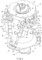
- FIG. 2 is a perspective view of the coil spring modeling apparatus 20.
- FIG. 3 is a side view of the coil spring modeling apparatus 20.
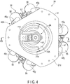
- FIG. 4 is a bottom view of the coil spring modeling apparatus 20.
- FIG. 5 is a cross-sectional view taken along line F5-F5 of FIG. 4 .
- a strut 2A ( FIG. 5 ) which is used in the coil spring modeling apparatus 20 comprises an outer tube 4A as a first strut element, a rod 5A as a second strut element, a lower spring seat 10A, a bracket 11A, and an upper spring seat 15A.
- the lower spring seat 10A is attached to the outer tube 4A.
- the upper spring seat 15A is disposed near the upper end of the rod 5A above the lower spring seat 10A.
- the rod 5A can be moved along axis L 1 (strut axis) relative to the outer tube 4A.
- the coil spring modeling apparatus 20 comprises a first attachment member 21, a second attachment member 22, a first seat adapter 27, a second seat adapter 28, an actuator unit 30 comprising a Stewart-platform-type parallel mechanism, a hydraulic pressure supply device 37, a first inner load cell 41, a second inner load cell 42, a base member 45, a rotation support mechanism 50, a controller 70, etc.
- the first attachment member 21 is secured to the lower spring seat 10A.
- the first attachment member 21 comprises a first disk portion 21a disposed above the lower spring seat 10A, a first extending portion 21b having a cylindrical shape which extends downward from the first disk portion 21a, and a first flange portion 21c projecting outward from the lower end of the first extending portion 21b. That is, the first attachment member 21 is substantially shaped like a hat.
- a lower joint connection portion 25 is circumferentially provided at each of six places in the first flange portion 21c.
- the second attachment member 22 is secured to the upper spring seat 15A.
- the second attachment member 22 comprises a second disk portion 22a disposed below the upper spring seat 15A, a second extending portion 22b having a cylindrical shape which extends upward from the second disk portion 22a, and a second flange portion 22c projecting outward from the upper end of the second extending portion 22b. That is, the second attachment member 22 is shaped like an upside-down hat.
- An upper joint connection portion 26 is circumferentially provided at each of six places in the second flange portion 22c.
- the first seat adapter 27 is arranged on the lower spring seat 10A.
- the first seat adapter 27 is formed of a light alloy whose specific gravity is smaller than that of iron such as aluminum alloy, and has a flat upper surface 27a.
- a lower surface 27b of the first seat adapter 27 has a shape which fits into the lower spring seat 10A.
- the second seat adapter 28 is arranged under the upper spring seat 15A.
- the second seat adapter 28 is also formed of a light alloy such as aluminum alloy, and has a flat lower surface 28a.
- An upper surface 28b of the second seat adapter 28 has a shape which contacts the upper spring seat 15A.
- the lower surface 28a of the second seat adapter 28 is parallel to the lower surface 27b of the first seat adapter 27.
- the flange portion 21c of the first attachment member 21 is positioned below the lower spring seat 10A.
- the flange portion 22c of the second attachment member 22 is positioned above the upper spring seat 15A.
- the actuator unit 30 which extends and retracts by fluid pressure is arranged between these flange portions 21c and 22c.
- An example of the actuator unit 30 comprises a Stewart-platform-type parallel mechanism.
- FIG. 6 is a block diagram showing the structure of the coil spring modeling apparatus 20.
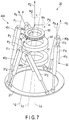
- FIG. 7 is a perspective view which schematically shows a part of the coil spring modeling apparatus 20.
- the actuator unit 30 comprising the Stewart-platform-type parallel mechanism includes six hydraulic cylinders 31 1 to 31 6 . These hydraulic cylinders 31 1 to 31 6 are arranged such that their inclinations are changed alternately, that is, the angles of adjacent hydraulic cylinders with respect to vertical line H ( FIG. 6 ) are respectively + ⁇ and - ⁇ in turn.
- the hydraulic cylinder 31 1 comprises a piston rod 32 actuated by fluid pressure (for example, oil pressure), a first hydraulic chamber 33 which moves the piston rod 32 in a first direction (the extending side), and a second hydraulic chamber 34 which moves the piston rod 32 in a second direction (the retracting side).
- the first hydraulic chamber 33 and the second hydraulic chamber 34 are connected to the hydraulic pressure supply device 37 via hoses 35 and 36, respectively.
- the hydraulic cylinder 31 1 can be moved to the extending side or the retracting side by supplying fluid pressure produced by the hydraulic pressure supply device 37 to the first hydraulic chamber 33 or the second hydraulic chamber 34.
- the lower end of the hydraulic cylinder 31 1 is swingably connected to the joint connection portion 25 of the first attachment member 21 by a universal joint 38 typified by a ball joint.
- the upper end of the hydraulic cylinder 31 1 is swingably connected to the joint connection portion 26 of the second attachment member 22 by a universal joint 39 typified by a ball joint.
- linear displacement gauges 40 1 to 40 6 are provided, respectively.
- a spring height detection mechanism 40A is constituted of these displacement gauges 40 1 to 40 6 . Since the structures of the displacement gauges 40 1 to 40 6 are common to each other, the first displacement gauge 40 1 provided on the first hydraulic cylinder 31 1 will be described as a typical example of the displacement gauges.
- An example of the displacement gauge 40 1 is a linear variable differential transformer (LVDT) comprising a plunger 54.
- the displacement gauge 40 1 detects a linear displacement relative to a reference length of the hydraulic cylinder 31 1 (a reference position of the piston rod 32).
- linear displacement gauges such as an optical linear encoder and a magnetic linear scale may be adopted.
- a linear displacement gauge based on other detection principles may be adopted.
- the displacement gauge 40 1 is mounted on the hydraulic cylinder 31 1 by a mounting plate 55.
- the plunger 54 of the displacement gauge 40 1 is connected to a distal end of the piston rod 32 of the hydraulic cylinder 31 1 by means of a coupling member 56.
- a guide rod 57 is inserted into the mounting plate 55.
- the guide rod 57 is connected to the plunger 54 by the coupling member 56.
- the piston rod 32, the plunger 54, and the guide rod 57 move along the axis of the hydraulic cylinder 31 1 in a state where they are kept parallel to one another.
- the guide rod 57 guides linear motion of the piston rod 32 and the plunger 54. Note that since the structures of the other displacement gauges 40 2 to 40 6 have commonalities with the first displacement gauge 40 1 , common reference numbers are assigned to common parts in FIGS. 2 to 5 .
- the first inner load cell 41 is arranged between the disk portion 21a of the first attachment member 21 and the first seat adapter 27.
- the first inner load cell 41 is accommodated within the first attachment member 21, and is disposed above the lower spring seat 10A.
- the first inner load cell 41 comprises a through-hole 41a into which the outer tube 4A is inserted, a flat upper surface 41b which contacts a lower surface of the first disk portion 21a, and a flat lower surface 41c which contacts the upper surface 27a of the first seat adapter 27, and has an annular shape as a whole.
- the first inner load cell 41 is secured to the first seat adapter 27 such that the upper surface 41b and the lower surface 41c of the first inner load cell 41 are perpendicular to axis L 1 .
- the first inner load cell 41 is arranged coaxially with the rotation support mechanism 50, that is, the center of the inner load cell 41 conforms to axis L 1 .
- the first inner load cell 41 detects the axial force acting on the upper surface 27a of the first seat adapter 27, and a moment about the axis.
- the first inner load cell 41 can rotate about axis L 1 together with the outer tube 4A, the lower spring seat 10A, the first seat adapter 27, and the first attachment member 21.
- the second inner load cell 42 is arranged between the disk portion 22a of the second attachment member 22 and the second seat adapter 28.
- the second inner load cell 42 is accommodated within the second attachment member 22, and is disposed below the upper spring seat 15A.
- the second inner load cell 42 comprises a through-hole 42a into which the rod 5A is inserted, a flat lower surface 42b which contacts an upper surface of the second disk portion 22a, and a flat upper surface 42c which contacts the lower surface 28a of the second seat adapter 28, and has an annular shape as a whole.
- the second inner load cell 42 is secured to the second seat adapter 28 such that the lower surface 42b and the upper surface 42c of the second inner load cell 42 are perpendicular to axis L 1 .
- the second inner load cell 42 is arranged coaxially with the rotation support mechanism 50, that is, the center of the inner load cell 42 conforms to axis L 1 .
- the second inner load cell 42 detects the axial force acting on the lower surface 28a of the second seat adapter 28, and a moment about the axis.
- the second inner load cell 42 can rotate about axis L 1 together with the upper spring seat 15A, the second attachment member 22, and the second seat adapter 28.
- the rotation support mechanism 50 is disposed between the upper spring seat 15A and the base member 45.
- the rotation support mechanism 50 rotatably supports the actuator unit 30 about axis L 1 with respect to the base member 45.
- An example of the rotation support mechanism 50 is a ball bearing, and the rotation support mechanism 50 comprises a lower ring member 51, an upper ring member 52, and a plurality of rolling members 53 accommodated between these ring members 51 and 52.
- the lower ring member 51 is disposed on an upper surface of the upper spring seat 15A.
- the upper ring member 52 is disposed on a lower surface of the base member 45.
- the actuator unit 30 comprising the Stewart-platform-type parallel mechanism forms a field of arbitrary force of six degrees of freedom by combining axial forces P 1 to P 6 shown in FIG. 7 . That is, of vectors of force produced by six hydraulic cylinders 31 1 to 31 6 , a resultant of components along axis L 1 constitutes a reactive force corresponding to that of a coil spring. For example, if a value obtained by combining the six axial forces P 1 to P 6 is positive, an upward force P Z along axis L 1 is produced.
- moment M Z a total of moments that the six axial forces P 1 to P 6 have an effect on around axis L 1 constitutes moment M Z about axis L 1 .
- moment M Z a total of moments that the six axial forces P 1 to P 6 have an effect on around axis L 1 constitutes moment M Z about axis L 1 .
- the total of forces produced by three hydraulic cylinders 31 1 , 31 3 , and 31 5 i.e., the axial forces that produce the positive moment M Z
- the total of forces of the other three hydraulic cylinders 31 2 , 31 4 , and 31 6 i.e., the axial forces that produce the negative moment M Z
- moment M Z having a positive value is produced at an upper end of the actuator unit 30 (the upper spring seat 15A).
- components around the axes of vectors of forces produced by the six hydraulic cylinders 31 1 to 31 6 correspond to the moment (M Z ) about axis L 1 .
- a moment (a kingpin moment) about kingpin axis L 2 is produced by the effect of the six-component force. Accordingly, it is possible to measure the moment about kingpin axis L 2 while changing the six-component force by the actuator unit 30.
- the displacement gauges 40 1 to 40 6 detect amounts of displacement relative to the reference lengths of the hydraulic cylinders 31 1 to 31 6 , respectively. Further, the hydraulic pressure supply device 37 supplies fluid pressure corresponding to the amounts of displacement detected by the displacement gauges 40 1 to 40 6 to the hydraulic cylinders 31 1 to 31 6 , respectively. Since the functions of the displacement gauges 40 1 to 40 6 are common to each other, the first displacement gauge 40 1 provided on the first hydraulic cylinder 31 1 will be described as a typical example of the displacement gauges.
- An output of the displacement gauge 40 1 is input to the controller 70.
- the controller 70 calculates a vertical displacement relative to the reference height of the hydraulic cylinder 31 1 based on the amount of displacement of the hydraulic cylinder 31 1 detected by the displacement gauge 40 1 .
- a vertical load obtained by multiplying the vertical displacement by a spring constant is added to an initial vertical load.
- fluid pressure B1 is supplied to the hydraulic cylinder 31 1 , as shown in line B in FIG. 8 .
- fluid pressure B2 (B2>B1) is supplied to the hydraulic cylinder 31 1 .
- fluid pressure B3 (B3>B2) is supplied to the hydraulic cylinder 31 1 .
- the coil spring modeling apparatus 20 of the present embodiment performs the load control (control of reactive force) having the feature of spring constant as in the case of the actual coil spring, on the basis of the amounts of displacement of the hydraulic cylinder 31 1 to 31 6 detected by the displacement gauges 40 1 to 40 6 , respectively.
- a liner displacement gauge 40B shown by a two-dot chain line in FIG. 5 may be arranged between the attachment members 21 and 22, and a vertical displacement may be directly detected by this liner displacement gauge 40B.
- a performance test of the strut 2A (for example, measurement of the sliding resistance of the strut 2A and the kingpin moment) can be performed by using the coil spring modeling apparatus 20 of the present embodiment.
- FIGS. 5 and 6 show reference number 80, which represents a part of a load testing machine.
- a predetermined load is applied to the coil spring modeling apparatus 20 by the load testing machine. Since the distance between the lower spring seat 10A and the upper spring seat 15A is reduced by the load, a vertical reaction is produced. While this vertical reaction is being produced, the base member 45 is moved vertically with, for example, vertical strokes of ⁇ 5 mm, and a rectangular waveform of 0.5 Hz, and the load is measured by an external load cell 81.
- the frictional force produced in the strut 2A can be evaluated as a half of the value of hysteresis of the measured load.
- a kingpin moment (KPM) is produced in accordance with a geometric positional relationship between axis L 1 and kingpin axis L 2 .
- the actuator unit 30 is supported by the rotation support mechanism 50.
- the friction of the rotation support mechanism 50 affects the magnitude of the kingpin moment (KPM).
- KPM kingpin moment
- the coil spring modeling apparatus can be applied to other types of suspension system having a strut, i.e., suspension systems other than the McPherson-strut-type suspension.
- the actuator unit is not limited to a Stewart-platform-type parallel mechanism, and any actuator unit comprising a hydraulic or pneumatic cylinder which extends and retracts by pressure of a fluid (liquid or gas) may be adopted.
- a linear actuator including a ball screw and a servo motor, or a differential-transformer-type linear actuator may be adopted.
- each of the elements which constitutes the coil spring modeling apparatus such as the first and second attachment members, the displacement gauge which constitutes the spring height detection mechanism, and the hydraulic pressure supply device, may be modified variously in implementing the present invention.
Landscapes
- Engineering & Computer Science (AREA)
- General Physics & Mathematics (AREA)
- Physics & Mathematics (AREA)
- Business, Economics & Management (AREA)
- Educational Administration (AREA)
- Mathematical Optimization (AREA)
- Mathematical Physics (AREA)
- Pure & Applied Mathematics (AREA)
- Computational Mathematics (AREA)
- Algebra (AREA)
- Mathematical Analysis (AREA)
- Educational Technology (AREA)
- Theoretical Computer Science (AREA)
- General Engineering & Computer Science (AREA)
- Automation & Control Theory (AREA)
- Mechanical Engineering (AREA)
- Vehicle Body Suspensions (AREA)
- Springs (AREA)
- Force Measurement Appropriate To Specific Purposes (AREA)
Abstract
Description
- The present invention relates to a coil spring modeling apparatus capable of producing a reactive force (repulsive force) corresponding to compression of a helical spring such as a suspension coil spring, and a method of controlling the same.
- As an example of a vehicle suspension system, a McPherson-strut-type suspension is known. The McPherson-strut-type suspension comprises a coil spring, and a strut (a shock absorber) provided inside of the coil spring. The coil spring is compressed by a load applied from above the coil spring, and is extended and retracted in accordance with the load. The strut is also extended and retracted.
- In the McPherson-strut-type suspension, in order to reduce the sliding resistance of a strut, offsetting a force line position (FLP) of a coil spring from the center line of the coil spring is known. For example, the force line position (FLP) of a coil spring is set at a position where the friction of the strut is minimal. For this reason, the relationship between a force line position (FLP) of a coil spring and the sliding resistance of a strut must be specified. However, producing a variety of coil springs whose force line positions are different by way of trial is time consuming and costly. Thus, instead of using the coil spring, using a coil spring modeling apparatus has been proposed.
- For example, a coil spring modeling apparatus disclosed in
U.S. Patent No. 7,606,690 (Patent Literature 1) is known. Also, an improved coil spring modeling apparatus is disclosed in "Research of Effect of Coil Spring Reaction Force Line on Vehicle Characteristics by Universal Spring" (Non-Patent Literature 1), onpages 21 to 24 of the proceedings, presentation of which was made in the conference held by the Japan Society of Spring Engineers (in Nagoya) on November 1, 2013, and "Experimental Study on the Effect of Coil Spring Reaction Force Vector on Suspension Characteristics" of SAE 2014 (Non-Patent Literature 2), presentation of which was made in the U.S. (Detroit) on April 8, 2014. The coil spring modeling apparatus disclosed in the above documents has a Stewart-platform-type parallel mechanism comprising six hydraulic cylinders. By actuating each of the hydraulic cylinders by fluid pressure, a reactive force corresponding to compression of a coil spring can be produced. - A coil spring has its length (deflection) changed in accordance with a compression load applied in the axial direction. The length (deflection) of a coil spring whose spring constant is invariable is increased in proportion to the load applied to the spring. Depending on the specification of a suspension comprising a coil spring, the characteristics (for example, the sliding resistance of a strut and a kingpin moment) may be changed in accordance with the change in length (the amount of compression) of the coil spring. Moreover, the spring constant is not necessarily invariable depending on the type of coil spring. For example, there exists a coil spring whose spring constant increases as the compression increases.
- In the conventional coil spring modeling apparatuses disclosed in
Patent Literature 1 andNon-Patent Literatures - Accordingly, the present invention aims to provide a coil spring modeling apparatus capable of producing a reactive force corresponding to the amount of compression in each of the hydraulic cylinders, and modeling various coil springs and a method of controlling the same.
- According to an embodiment of the present invention, a coil spring modeling apparatus provided on a strut, which comprises a lower spring seat and an upper spring seat, comprises: a first attachment member disposed on the lower spring seat; a second attachment member disposed on the upper spring seat; an actuator unit which is arranged between the first attachment member and the second attachment member, and extends and retracts; a spring height detection mechanism; and a controller. The spring height detection mechanism is configured to detect an amount of displacement with respect to a distance between the first attachment member and the second attachment member. The controller is configured to control the actuator unit according to the amount of displacement detected by the spring height detection mechanism.
- An example of the actuator unit comprises a Stewart-platform-type parallel mechanism including six hydraulic cylinders arranged with their inclinations changed alternately between the first attachment member and the second attachment member. An example of the spring height detection mechanism comprises linear displacement gauges which are provided on the hydraulic cylinders, respectively. These displacement gauges detect amounts of displacement relative to reference lengths of the hydraulic cylinders, respectively. An example of the displacement gauge is a linear variable differential transformer (LVDT) comprising a plunger. Further, a guide rod which guides the linear motion of the plunger may be provided. Furthermore, a first inner load cell configured to detect an axial force applied to the lower spring seat and a moment about the axis, and a second inner load cell configured to detect an axial force applied to the upper spring seat and a moment about the axis should preferably be provided.
- The coil spring modeling apparatus comprising the displacement gauges calculates vertical displacements relative to the reference heights, on the basis of the amounts of displacement of the respective hydraulic cylinders detected by the displacement gauges. A vertical load obtained by multiplying the vertical displacement by a spring constant is added to an initial vertical load. By controlling the fluid pressure of each of the hydraulic cylinders with this additional value, load control (control of reactive force) having the feature of spring constant is carried out as in the case of the actual coil spring.
- According to the coil spring modeling apparatus of the present embodiment, a reactive force corresponding to the amount of compression can be produced in each of the hydraulic cylinders as in the case of an actual coil spring having a given spring constant. Thus, even if the actual coil spring is not used, a characteristic test equivalent to that performed in a suspension comprising a coil spring can be performed.
-
-
FIG. 1 is a cross-sectional view of a McPherson-strut-type suspension. -
FIG. 2 is a perspective view of a coil spring modeling apparatus according to an embodiment. -
FIG. 3 is a side view of the coil spring modeling apparatus shown inFIG. 2 . -
FIG. 4 is a bottom view of the coil spring modeling apparatus shown inFIG. 2 . -
FIG. 5 is a cross-sectional view taken along line F5-F5 ofFIG. 4 . -
FIG. 6 is a block diagram showing a schematic structure of the coil spring modeling apparatus shown inFIG. 2 . -
FIG. 7 is a perspective view schematically showing a part of the coil spring modeling apparatus shown inFIG. 2 . -
FIG. 8 is a graph showing the relationship between the amount of displacement and the fluid pressure of a hydraulic cylinder. -
FIG. 1 shows a McPherson-strut-type suspension 1, which is an example of a suspension system used in vehicles. Thesuspension 1 comprises a shock absorber as astrut 2, and a suspension coil spring 3 (which is hereinafter simply referred to as a coil spring 3). Thestrut 2 comprises anouter tube 4 as a first strut element, and arod 5 as a second strut element. Therod 5 is inserted into theouter tube 4. A damping force generation mechanism is provided at a distal end of therod 5 inserted into theouter tube 4. Theouter tube 4 and therod 5 can be moved relatively along axis L1 (strut axis). - The
outer tube 4 is provided with alower spring seat 10. At the lower end of theouter tube 4, abracket 11 is provided. Aknuckle member 12 is mounted on thebracket 11. A wheel axis is supported by theknuckle member 12. Anupper spring seat 15 is provided near the upper end of therod 5. Amount insulator 17 is provided between theupper spring seat 15 and abody member 16. When a steering operation is performed, thestrut 2 is pivoted about kingpin axis L2 by the steering control force input to theknuckle member 12. Thecoil spring 3 is provided in a state in which thecoil spring 3 is compressed between thelower spring seat 10 and theupper spring seat 15. - A coil
spring modeling apparatus 20 according to an embodiment will now be described with reference toFIGS. 2 to 8 .FIG. 2 is a perspective view of the coilspring modeling apparatus 20.FIG. 3 is a side view of the coilspring modeling apparatus 20.FIG. 4 is a bottom view of the coilspring modeling apparatus 20.FIG. 5 is a cross-sectional view taken along line F5-F5 ofFIG. 4 . - A
strut 2A (FIG. 5 ) which is used in the coilspring modeling apparatus 20 comprises anouter tube 4A as a first strut element, arod 5A as a second strut element, alower spring seat 10A, abracket 11A, and anupper spring seat 15A. Thelower spring seat 10A is attached to theouter tube 4A. Theupper spring seat 15A is disposed near the upper end of therod 5A above thelower spring seat 10A. Therod 5A can be moved along axis L1 (strut axis) relative to theouter tube 4A. - The coil
spring modeling apparatus 20 comprises afirst attachment member 21, asecond attachment member 22, afirst seat adapter 27, asecond seat adapter 28, anactuator unit 30 comprising a Stewart-platform-type parallel mechanism, a hydraulicpressure supply device 37, a firstinner load cell 41, a secondinner load cell 42, abase member 45, arotation support mechanism 50, acontroller 70, etc. - The
first attachment member 21 is secured to thelower spring seat 10A. Thefirst attachment member 21 comprises afirst disk portion 21a disposed above thelower spring seat 10A, a first extendingportion 21b having a cylindrical shape which extends downward from thefirst disk portion 21a, and afirst flange portion 21c projecting outward from the lower end of the first extendingportion 21b. That is, thefirst attachment member 21 is substantially shaped like a hat. A lowerjoint connection portion 25 is circumferentially provided at each of six places in thefirst flange portion 21c. - The
second attachment member 22 is secured to theupper spring seat 15A. Thesecond attachment member 22 comprises asecond disk portion 22a disposed below theupper spring seat 15A, a second extendingportion 22b having a cylindrical shape which extends upward from thesecond disk portion 22a, and asecond flange portion 22c projecting outward from the upper end of the second extendingportion 22b. That is, thesecond attachment member 22 is shaped like an upside-down hat. An upperjoint connection portion 26 is circumferentially provided at each of six places in thesecond flange portion 22c. - The
first seat adapter 27 is arranged on thelower spring seat 10A. Thefirst seat adapter 27 is formed of a light alloy whose specific gravity is smaller than that of iron such as aluminum alloy, and has a flatupper surface 27a. Alower surface 27b of thefirst seat adapter 27 has a shape which fits into thelower spring seat 10A. - The
second seat adapter 28 is arranged under theupper spring seat 15A. Thesecond seat adapter 28 is also formed of a light alloy such as aluminum alloy, and has a flatlower surface 28a. Anupper surface 28b of thesecond seat adapter 28 has a shape which contacts theupper spring seat 15A. Thelower surface 28a of thesecond seat adapter 28 is parallel to thelower surface 27b of thefirst seat adapter 27. - The
flange portion 21c of thefirst attachment member 21 is positioned below thelower spring seat 10A. Theflange portion 22c of thesecond attachment member 22 is positioned above theupper spring seat 15A. Theactuator unit 30 which extends and retracts by fluid pressure is arranged between theseflange portions actuator unit 30 comprises a Stewart-platform-type parallel mechanism. -
FIG. 6 is a block diagram showing the structure of the coilspring modeling apparatus 20.FIG. 7 is a perspective view which schematically shows a part of the coilspring modeling apparatus 20. Theactuator unit 30 comprising the Stewart-platform-type parallel mechanism includes six hydraulic cylinders 311 to 316. These hydraulic cylinders 311 to 316 are arranged such that their inclinations are changed alternately, that is, the angles of adjacent hydraulic cylinders with respect to vertical line H (FIG. 6 ) are respectively +θ and -θ in turn. - Since the structures of the six hydraulic cylinders 311 to 316 are common to each other, the first hydraulic cylinder 311 will be described as a typical example of the hydraulic cylinders. The hydraulic cylinder 311 comprises a
piston rod 32 actuated by fluid pressure (for example, oil pressure), a firsthydraulic chamber 33 which moves thepiston rod 32 in a first direction (the extending side), and a secondhydraulic chamber 34 which moves thepiston rod 32 in a second direction (the retracting side). The firsthydraulic chamber 33 and the secondhydraulic chamber 34 are connected to the hydraulicpressure supply device 37 viahoses - The hydraulic cylinder 311 can be moved to the extending side or the retracting side by supplying fluid pressure produced by the hydraulic
pressure supply device 37 to the firsthydraulic chamber 33 or the secondhydraulic chamber 34. The lower end of the hydraulic cylinder 311 is swingably connected to thejoint connection portion 25 of thefirst attachment member 21 by a universal joint 38 typified by a ball joint. The upper end of the hydraulic cylinder 311 is swingably connected to thejoint connection portion 26 of thesecond attachment member 22 by a universal joint 39 typified by a ball joint. - In the hydraulic cylinders 311 to 316, linear displacement gauges 401 to 406 are provided, respectively. A spring
height detection mechanism 40A is constituted of these displacement gauges 401 to 406. Since the structures of the displacement gauges 401 to 406 are common to each other, the first displacement gauge 401 provided on the first hydraulic cylinder 311 will be described as a typical example of the displacement gauges. - An example of the displacement gauge 401 is a linear variable differential transformer (LVDT) comprising a
plunger 54. The displacement gauge 401 detects a linear displacement relative to a reference length of the hydraulic cylinder 311 (a reference position of the piston rod 32). As other examples of the displacement gauge 401, linear displacement gauges such as an optical linear encoder and a magnetic linear scale may be adopted. Alternatively, a linear displacement gauge based on other detection principles may be adopted. - The displacement gauge 401 is mounted on the hydraulic cylinder 311 by a mounting
plate 55. Theplunger 54 of the displacement gauge 401 is connected to a distal end of thepiston rod 32 of the hydraulic cylinder 311 by means of acoupling member 56. Aguide rod 57 is inserted into the mountingplate 55. Theguide rod 57 is connected to theplunger 54 by thecoupling member 56. Thepiston rod 32, theplunger 54, and theguide rod 57 move along the axis of the hydraulic cylinder 311 in a state where they are kept parallel to one another. Theguide rod 57 guides linear motion of thepiston rod 32 and theplunger 54. Note that since the structures of the other displacement gauges 402 to 406 have commonalities with the first displacement gauge 401, common reference numbers are assigned to common parts inFIGS. 2 to 5 . - The first
inner load cell 41 is arranged between thedisk portion 21a of thefirst attachment member 21 and thefirst seat adapter 27. The firstinner load cell 41 is accommodated within thefirst attachment member 21, and is disposed above thelower spring seat 10A. The firstinner load cell 41 comprises a through-hole 41a into which theouter tube 4A is inserted, a flatupper surface 41b which contacts a lower surface of thefirst disk portion 21a, and a flatlower surface 41c which contacts theupper surface 27a of thefirst seat adapter 27, and has an annular shape as a whole. The firstinner load cell 41 is secured to thefirst seat adapter 27 such that theupper surface 41b and thelower surface 41c of the firstinner load cell 41 are perpendicular to axis L1. - The first
inner load cell 41 is arranged coaxially with therotation support mechanism 50, that is, the center of theinner load cell 41 conforms to axis L1. The firstinner load cell 41 detects the axial force acting on theupper surface 27a of thefirst seat adapter 27, and a moment about the axis. The firstinner load cell 41 can rotate about axis L1 together with theouter tube 4A, thelower spring seat 10A, thefirst seat adapter 27, and thefirst attachment member 21. - The second
inner load cell 42 is arranged between thedisk portion 22a of thesecond attachment member 22 and thesecond seat adapter 28. The secondinner load cell 42 is accommodated within thesecond attachment member 22, and is disposed below theupper spring seat 15A. The secondinner load cell 42 comprises a through-hole 42a into which therod 5A is inserted, a flatlower surface 42b which contacts an upper surface of thesecond disk portion 22a, and a flatupper surface 42c which contacts thelower surface 28a of thesecond seat adapter 28, and has an annular shape as a whole. The secondinner load cell 42 is secured to thesecond seat adapter 28 such that thelower surface 42b and theupper surface 42c of the secondinner load cell 42 are perpendicular to axis L1. - Like the first
inner load cell 41, the secondinner load cell 42 is arranged coaxially with therotation support mechanism 50, that is, the center of theinner load cell 42 conforms to axis L1. The secondinner load cell 42 detects the axial force acting on thelower surface 28a of thesecond seat adapter 28, and a moment about the axis. The secondinner load cell 42 can rotate about axis L1 together with theupper spring seat 15A, thesecond attachment member 22, and thesecond seat adapter 28. - The
rotation support mechanism 50 is disposed between theupper spring seat 15A and thebase member 45. Therotation support mechanism 50 rotatably supports theactuator unit 30 about axis L1 with respect to thebase member 45. An example of therotation support mechanism 50 is a ball bearing, and therotation support mechanism 50 comprises alower ring member 51, anupper ring member 52, and a plurality of rollingmembers 53 accommodated between thesering members lower ring member 51 is disposed on an upper surface of theupper spring seat 15A. Theupper ring member 52 is disposed on a lower surface of thebase member 45. - The operation of the coil
spring modeling apparatus 20 will now be described. - The
actuator unit 30 comprising the Stewart-platform-type parallel mechanism forms a field of arbitrary force of six degrees of freedom by combining axial forces P1 to P6 shown inFIG. 7 . That is, of vectors of force produced by six hydraulic cylinders 311 to 316, a resultant of components along axis L1 constitutes a reactive force corresponding to that of a coil spring. For example, if a value obtained by combining the six axial forces P1 to P6 is positive, an upward force PZ along axis L1 is produced. - When the
actuator unit 30 is compressed between thelower spring seat 10A and theupper spring seat 15A, of vectors of force produced by the six hydraulic cylinders 311 to 316, an axial force is applied to thelower spring seat 10A. In this case, three orthogonal axial forces (PX, PY, PZ) with respect to the coordinate system ofFIG. 7 , and three moments (MX, MY, MZ) are produced. A six-component force (PX, PY, PZ, MX, MY, MZ) applied to thelower spring seat 10A is detected by the firstinner load cell 41 and input to the controller 70 (FIG. 6 ). Further, a six-component force applied to theupper spring seat 15A is detected by the secondinner load cell 42 and input to thecontroller 70. Based on these six-component forces, reactive force central position (load axis) L3 is calculated. - Also, a total of moments that the six axial forces P1 to P6 have an effect on around axis L1 constitutes moment MZ about axis L1. For example, in
FIG. 7 , if the total of forces produced by three hydraulic cylinders 311, 313, and 315 (i.e., the axial forces that produce the positive moment MZ) is greater than the total of forces of the other three hydraulic cylinders 312, 314, and 316 (i.e., the axial forces that produce the negative moment MZ), moment MZ having a positive value is produced at an upper end of the actuator unit 30 (theupper spring seat 15A). That is, components around the axes of vectors of forces produced by the six hydraulic cylinders 311 to 316 correspond to the moment (MZ) about axis L1. Also at kingpin axis L2, a moment (a kingpin moment) about kingpin axis L2 is produced by the effect of the six-component force. Accordingly, it is possible to measure the moment about kingpin axis L2 while changing the six-component force by theactuator unit 30. - The displacement gauges 401 to 406 detect amounts of displacement relative to the reference lengths of the hydraulic cylinders 311 to 316, respectively. Further, the hydraulic
pressure supply device 37 supplies fluid pressure corresponding to the amounts of displacement detected by the displacement gauges 401 to 406 to the hydraulic cylinders 311 to 316, respectively. Since the functions of the displacement gauges 401 to 406 are common to each other, the first displacement gauge 401 provided on the first hydraulic cylinder 311 will be described as a typical example of the displacement gauges. - An output of the displacement gauge 401 is input to the
controller 70. Thecontroller 70 calculates a vertical displacement relative to the reference height of the hydraulic cylinder 311 based on the amount of displacement of the hydraulic cylinder 311 detected by the displacement gauge 401. A vertical load obtained by multiplying the vertical displacement by a spring constant is added to an initial vertical load. By controlling the fluid pressure of the hydraulic cylinder 311 with this additional value, load control (control of reactive force) having the feature of spring constant is carried out as in the case of the actual coil spring. - For example, if the spring constant is invariable (i.e., if the spring has linear characteristics), when displacement amount S1 is detected, fluid pressure A1 is supplied to the hydraulic cylinder 311, as shown in line A in
FIG. 8 . When displacement amount S2 is detected as the load is increased, fluid pressure A2 (A2>A1) is supplied to the hydraulic cylinder 311. When displacement amount S3 is detected as the load is further increased, fluid pressure A3 (A3>A2) is supplied to the hydraulic cylinder 311. - If the spring constant is variable and changes progressively with knee (i.e., if the spring has non-linear characteristics), when displacement amount S1 is detected, fluid pressure B1 is supplied to the hydraulic cylinder 311, as shown in line B in
FIG. 8 . When displacement amount S2 is detected as the load is increased, fluid pressure B2 (B2>B1) is supplied to the hydraulic cylinder 311. When displacement amount S3 is detected as the load is further increased, fluid pressure B3 (B3>B2) is supplied to the hydraulic cylinder 311. - If the spring constant is variable and changes progressively (i.e., if the spring has non-linear characteristics), when displacement amount S1 is detected, fluid pressure C1 is supplied to the hydraulic cylinder 311, as shown in line C in
FIG. 8 . When displacement amount S2 is detected as the load is increased, fluid pressure C2 (C2>C1) is supplied to the hydraulic cylinder 311. When displacement amount S3 is detected as the load is further increased, fluid pressure C3 (C3>C2) is supplied to the hydraulic cylinder 311. - As can be seen, the coil
spring modeling apparatus 20 of the present embodiment performs the load control (control of reactive force) having the feature of spring constant as in the case of the actual coil spring, on the basis of the amounts of displacement of the hydraulic cylinder 311 to 316 detected by the displacement gauges 401 to 406, respectively. As another embodiment of the spring height detection mechanism, aliner displacement gauge 40B shown by a two-dot chain line inFIG. 5 may be arranged between theattachment members liner displacement gauge 40B. - A performance test of the
strut 2A (for example, measurement of the sliding resistance of thestrut 2A and the kingpin moment) can be performed by using the coilspring modeling apparatus 20 of the present embodiment.FIGS. 5 and6 show reference number 80, which represents a part of a load testing machine. A predetermined load is applied to the coilspring modeling apparatus 20 by the load testing machine. Since the distance between thelower spring seat 10A and theupper spring seat 15A is reduced by the load, a vertical reaction is produced. While this vertical reaction is being produced, thebase member 45 is moved vertically with, for example, vertical strokes of ±5 mm, and a rectangular waveform of 0.5 Hz, and the load is measured by anexternal load cell 81. The frictional force produced in thestrut 2A can be evaluated as a half of the value of hysteresis of the measured load. - When a moment (MZ) about axis L1 is produced between the
lower spring seat 10A and theupper spring seat 15A by controlling the fluid pressure supplied to each of the hydraulic cylinders 311 to 316, a kingpin moment (KPM) is produced in accordance with a geometric positional relationship between axis L1 and kingpin axis L2. Theactuator unit 30 is supported by therotation support mechanism 50. The friction of therotation support mechanism 50 affects the magnitude of the kingpin moment (KPM). In a state where a predetermined vertical reaction is produced between thelower spring seat 10A and theupper spring seat 15A, a kingpin moment (KPM) which has been produced is detected. - The coil spring modeling apparatus according to the embodiment of the present invention can be applied to other types of suspension system having a strut, i.e., suspension systems other than the McPherson-strut-type suspension. The actuator unit is not limited to a Stewart-platform-type parallel mechanism, and any actuator unit comprising a hydraulic or pneumatic cylinder which extends and retracts by pressure of a fluid (liquid or gas) may be adopted. As other examples of the actuator unit, a linear actuator including a ball screw and a servo motor, or a differential-transformer-type linear actuator may be adopted. Further, needless to say, the structure, form, and arrangement or the like of each of the elements which constitutes the coil spring modeling apparatus, such as the first and second attachment members, the displacement gauge which constitutes the spring height detection mechanism, and the hydraulic pressure supply device, may be modified variously in implementing the present invention.
- 2A · · · strut (shock absorber), 10A · · · lower spring seat, 15A · · · upper spring seat, 20 · · · coil spring modeling apparatus, 21 · · · first attachment member, 22 · · · second attachment member, 27 · · · first seat adapter, 28 · · · second seat adapter, 30 · · · actuator unit, 311-316 · · · hydraulic cylinder, 37 · · · hydraulic pressure supply device, 40A · · · spring height detection mechanism, 401-406 · · · displacement gauge, 41 · · · first inner load cell, 42 · · · second inner load cell, 54 · · · plunger, 57 · · · guide rod, 70 · · · controller
Claims (6)
- A coil spring modeling apparatus (20) provided on a strut (2A) comprising a lower spring seat (10A) and an upper spring seat (15A), the coil spring modeling apparatus (20) comprising:a first attachment member (21) disposed on the lower spring seat (10A);a second attachment member (22) disposed on the upper spring seat (15A);an actuator unit (30) which is arranged between the first attachment member (21) and the second attachment member (22), and extends and retracts;a spring height detection mechanism (40A) configured to detect an amount of displacement with respect to a distance between the first attachment member (21) and the second attachment member (22); anda controller (70) configured to control the actuator unit (30) according to the amount of displacement detected by the spring height detection mechanism (40A).
- The apparatus (20) of Claim 1, wherein the actuator unit (30) comprises a Stewart-platform-type parallel mechanism including six hydraulic cylinders (311-316) arranged with their inclinations changed alternately between the first attachment member (21) and the second attachment member (22).
- The apparatus (20) of Claim 2, wherein the spring height detection mechanism (40A) comprises displacement gauges (401-406) which are provided on the hydraulic cylinders (311-316) and detect amounts of displacement relative to reference lengths of the hydraulic cylinders (311-316), respectively.
- The apparatus (20) of Claim 3, wherein each of the displacement gauges (401-406) is an LVDT comprising a plunger (54), and the apparatus (20) further comprises a guide rod (57) which is arranged parallel to the plunger (54) and guides a linear motion of the plunger (54).
- The apparatus (20) of Claim 1, further comprising a first inner load cell (41) configured to detect an axial force applied to the lower spring seat (10A) and a moment about the axis, and a second inner load cell (42) configured to detect an axial force applied to the upper spring seat (15A) and a moment about the axis.
- A method of controlling a coil spring modeling apparatus (20) which comprises hydraulic cylinders (311-316) arranged between a first attachment member (21) disposed on a lower spring seat (10A) and a second attachment member (22) disposed on an upper spring seat (15A), the method comprising:detecting an amount of displacement relative to a reference length of each of the hydraulic cylinders (311-316); andsupplying fluid pressure according to the amount of displacement to each of the hydraulic cylinders (311-316) .
Applications Claiming Priority (2)
| Application Number | Priority Date | Filing Date | Title |
|---|---|---|---|
| US14/620,855 US9811067B2 (en) | 2015-02-12 | 2015-02-12 | Coil spring modeling apparatus and method of the same |
| PCT/JP2016/054012 WO2016129648A1 (en) | 2015-02-12 | 2016-02-10 | Model coiled spring device and control method for same |
Publications (3)
| Publication Number | Publication Date |
|---|---|
| EP3258233A1 true EP3258233A1 (en) | 2017-12-20 |
| EP3258233A4 EP3258233A4 (en) | 2018-11-07 |
| EP3258233B1 EP3258233B1 (en) | 2023-05-24 |
Family
ID=56614769
Family Applications (1)
| Application Number | Title | Priority Date | Filing Date |
|---|---|---|---|
| EP16749291.7A Active EP3258233B1 (en) | 2015-02-12 | 2016-02-10 | Model coiled spring device and control method for same |
Country Status (9)
| Country | Link |
|---|---|
| US (1) | US9811067B2 (en) |
| EP (1) | EP3258233B1 (en) |
| JP (1) | JP6326511B2 (en) |
| KR (1) | KR101917553B1 (en) |
| CN (1) | CN107250750B (en) |
| ES (1) | ES2946182T3 (en) |
| HU (1) | HUE062104T2 (en) |
| PL (1) | PL3258233T3 (en) |
| WO (1) | WO2016129648A1 (en) |
Families Citing this family (3)
| Publication number | Priority date | Publication date | Assignee | Title |
|---|---|---|---|---|
| FR3033932B1 (en) * | 2015-03-16 | 2018-03-16 | Micro-Controle-Spectra Physics | SYSTEM FOR RELATIVE MOVEMENT BETWEEN TWO PLATES AND POSITIONING DEVICE COMPRISING SUCH A DISPLACEMENT SYSTEM. |
| CN108275039A (en) * | 2018-02-13 | 2018-07-13 | 天津大学 | A kind of engineering machinery shock absorbing seat based on Stewart mechanisms and intellectual material |
| CN111299703B (en) * | 2019-11-21 | 2022-02-08 | 深圳大学 | Machining device and precision machining machine tool |
Family Cites Families (17)
| Publication number | Priority date | Publication date | Assignee | Title |
|---|---|---|---|---|
| JPH0490916A (en) * | 1990-08-06 | 1992-03-24 | Honda Motor Co Ltd | Control method of suspension device for vehicle |
| US5322319A (en) * | 1990-09-17 | 1994-06-21 | Mitsubishi Jidosha Kogyo Kabushiki Kaisha | Active suspension apparatus for a vehicle |
| JP2805387B2 (en) * | 1990-09-17 | 1998-09-30 | 三菱自動車工業株式会社 | Active suspension system for vehicles |
| JP2963183B2 (en) * | 1990-10-15 | 1999-10-12 | 本田技研工業株式会社 | Control method for active suspension |
| JP3084904B2 (en) | 1992-04-06 | 2000-09-04 | 株式会社日立製作所 | Railway vehicle test apparatus and method |
| JPH0986125A (en) * | 1995-09-28 | 1997-03-31 | Nissan Motor Co Ltd | Strut suspension system |
| US7606690B2 (en) | 2001-12-18 | 2009-10-20 | Nhk International Corporation | Method and apparatus for modeling coil springs using a force field generator |
| US7110926B2 (en) * | 2003-10-29 | 2006-09-19 | Nhk International Corp. | Universal spring mechanism for automobile suspension system design |
| JP4647527B2 (en) | 2006-03-22 | 2011-03-09 | 財団法人鉄道総合技術研究所 | Vibration model device for articulated vehicle of magnetic levitation railway |
| JP4835415B2 (en) * | 2006-12-08 | 2011-12-14 | トヨタ自動車株式会社 | Motion conversion transmission device |
| US8214184B2 (en) | 2007-10-19 | 2012-07-03 | Nhk International Corp. | Reverse engineering based coil spring design method |
| JP4920006B2 (en) * | 2008-05-15 | 2012-04-18 | トヨタ自動車株式会社 | Vehicle suspension system |
| DE102010023539A1 (en) * | 2010-06-11 | 2011-12-15 | Audi Ag | Wheel suspension for steered wheels of vehicles, in particular motor vehicles |
| US9406411B2 (en) * | 2011-02-08 | 2016-08-02 | Accuray Incorporated | Automatic calibration for device with controlled motion range |
| US9506225B2 (en) * | 2011-10-11 | 2016-11-29 | Volvo Construction Equipment Ab | Actuator displacement measurement system in electronic hydraulic system of construction equipment |
| DE102014208298B4 (en) * | 2014-05-02 | 2018-06-21 | Ford Global Technologies, Llc | Cuff for a strut module of a vehicle as well as strut module and correspondingly equipped vehicle |
| KR102032450B1 (en) * | 2014-10-22 | 2019-10-21 | 주식회사 만도 | Active suspension apparatus for vehicle |
-
2015
- 2015-02-12 US US14/620,855 patent/US9811067B2/en active Active
-
2016
- 2016-02-10 PL PL16749291.7T patent/PL3258233T3/en unknown
- 2016-02-10 ES ES16749291T patent/ES2946182T3/en active Active
- 2016-02-10 JP JP2016574842A patent/JP6326511B2/en active Active
- 2016-02-10 WO PCT/JP2016/054012 patent/WO2016129648A1/en not_active Ceased
- 2016-02-10 KR KR1020177022382A patent/KR101917553B1/en not_active Expired - Fee Related
- 2016-02-10 CN CN201680010278.4A patent/CN107250750B/en active Active
- 2016-02-10 HU HUE16749291A patent/HUE062104T2/en unknown
- 2016-02-10 EP EP16749291.7A patent/EP3258233B1/en active Active
Also Published As
| Publication number | Publication date |
|---|---|
| JP6326511B2 (en) | 2018-05-16 |
| US20160239004A1 (en) | 2016-08-18 |
| HUE062104T2 (en) | 2023-09-28 |
| CN107250750B (en) | 2020-02-18 |
| CN107250750A (en) | 2017-10-13 |
| EP3258233B1 (en) | 2023-05-24 |
| PL3258233T3 (en) | 2023-10-02 |
| US9811067B2 (en) | 2017-11-07 |
| KR20170106378A (en) | 2017-09-20 |
| JPWO2016129648A1 (en) | 2017-09-28 |
| KR101917553B1 (en) | 2019-01-24 |
| ES2946182T3 (en) | 2023-07-13 |
| EP3258233A4 (en) | 2018-11-07 |
| WO2016129648A1 (en) | 2016-08-18 |
Similar Documents
| Publication | Publication Date | Title |
|---|---|---|
| EP3258234A1 (en) | Model coil spring device and control method for same | |
| JP2025071137A (en) | Coordinate positioning apparatus, method for controlling a coordinate positioning apparatus and computer program product for implementing the method - Patents.com | |
| EP2447696B1 (en) | Wind tunnel balance calibrator | |
| EP3258233B1 (en) | Model coiled spring device and control method for same | |
| CN100449196C (en) | Master-slave dual-parallel twelve-degree-of-freedom generalized force-compliant loading mechanism | |
| Brun et al. | Active control of blankholder in sheet metal stamping | |
| CN112900878A (en) | Concrete pump truck arm support control system and method and concrete pump truck | |
| RU172849U1 (en) | STAND FOR TESTS OF VIBRATION Dampers | |
| CN113063538B (en) | Distributed multi-dimensional force sensor | |
| CN114161890B (en) | Air suspension based on quasi-zero stiffness principle and structural design and optimization method thereof | |
| EP3258232B1 (en) | Model coiled spring device | |
| Okumura et al. | Development of a multistage six-axis force sensor with a high dynamic range | |
| CN211669390U (en) | Component type drilling strain gauge complete machine detection platform controlled by six degrees of freedom | |
| CN214748829U (en) | Inclinable transmission test bed | |
| CN107340096A (en) | Six degree of freedom integral stiffness is tested and rotary inertia is test bed | |
| CN207423446U (en) | Six degree of freedom integral stiffness is tested and rotary inertia is test bed | |
| Kienholz | A System for Suspending and Vibration-Isolating a Large Spacecraft for Testing in Vacuum | |
| Deulin et al. | Vacuum mechanisms of nanoscale precision |
Legal Events
| Date | Code | Title | Description |
|---|---|---|---|
| STAA | Information on the status of an ep patent application or granted ep patent |
Free format text: STATUS: THE INTERNATIONAL PUBLICATION HAS BEEN MADE |
|
| PUAI | Public reference made under article 153(3) epc to a published international application that has entered the european phase |
Free format text: ORIGINAL CODE: 0009012 |
|
| STAA | Information on the status of an ep patent application or granted ep patent |
Free format text: STATUS: REQUEST FOR EXAMINATION WAS MADE |
|
| 17P | Request for examination filed |
Effective date: 20170912 |
|
| AK | Designated contracting states |
Kind code of ref document: A1 Designated state(s): AL AT BE BG CH CY CZ DE DK EE ES FI FR GB GR HR HU IE IS IT LI LT LU LV MC MK MT NL NO PL PT RO RS SE SI SK SM TR |
|
| AX | Request for extension of the european patent |
Extension state: BA ME |
|
| DAV | Request for validation of the european patent (deleted) | ||
| DAX | Request for extension of the european patent (deleted) | ||
| A4 | Supplementary search report drawn up and despatched |
Effective date: 20181008 |
|
| RIC1 | Information provided on ipc code assigned before grant |
Ipc: B60G 17/015 20060101ALI20181001BHEP Ipc: G01L 5/00 20060101ALI20181001BHEP Ipc: B60G 15/06 20060101ALI20181001BHEP Ipc: G01L 5/16 20060101AFI20181001BHEP |
|
| STAA | Information on the status of an ep patent application or granted ep patent |
Free format text: STATUS: EXAMINATION IS IN PROGRESS |
|
| 17Q | First examination report despatched |
Effective date: 20210422 |
|
| REG | Reference to a national code |
Ref country code: DE Ref legal event code: R079 Ref document number: 602016079580 Country of ref document: DE Free format text: PREVIOUS MAIN CLASS: G01L0005160000 Ipc: G09B0023080000 |
|
| RIC1 | Information provided on ipc code assigned before grant |
Ipc: G09B 23/08 20060101AFI20220726BHEP |
|
| GRAP | Despatch of communication of intention to grant a patent |
Free format text: ORIGINAL CODE: EPIDOSNIGR1 |
|
| STAA | Information on the status of an ep patent application or granted ep patent |
Free format text: STATUS: GRANT OF PATENT IS INTENDED |
|
| INTG | Intention to grant announced |
Effective date: 20221216 |
|
| GRAS | Grant fee paid |
Free format text: ORIGINAL CODE: EPIDOSNIGR3 |
|
| GRAA | (expected) grant |
Free format text: ORIGINAL CODE: 0009210 |
|
| STAA | Information on the status of an ep patent application or granted ep patent |
Free format text: STATUS: THE PATENT HAS BEEN GRANTED |
|
| AK | Designated contracting states |
Kind code of ref document: B1 Designated state(s): AL AT BE BG CH CY CZ DE DK EE ES FI FR GB GR HR HU IE IS IT LI LT LU LV MC MK MT NL NO PL PT RO RS SE SI SK SM TR |
|
| REG | Reference to a national code |
Ref country code: GB Ref legal event code: FG4D |
|
| REG | Reference to a national code |
Ref country code: CH Ref legal event code: EP |
|
| REG | Reference to a national code |
Ref country code: DE Ref legal event code: R096 Ref document number: 602016079580 Country of ref document: DE |
|
| REG | Reference to a national code |
Ref country code: AT Ref legal event code: REF Ref document number: 1570034 Country of ref document: AT Kind code of ref document: T Effective date: 20230615 |
|
| REG | Reference to a national code |
Ref country code: IE Ref legal event code: FG4D |
|
| REG | Reference to a national code |
Ref country code: ES Ref legal event code: FG2A Ref document number: 2946182 Country of ref document: ES Kind code of ref document: T3 Effective date: 20230713 |
|
| REG | Reference to a national code |
Ref country code: LT Ref legal event code: MG9D |
|
| REG | Reference to a national code |
Ref country code: NL Ref legal event code: MP Effective date: 20230524 |
|
| REG | Reference to a national code |
Ref country code: HU Ref legal event code: AG4A Ref document number: E062104 Country of ref document: HU |
|
| REG | Reference to a national code |
Ref country code: AT Ref legal event code: MK05 Ref document number: 1570034 Country of ref document: AT Kind code of ref document: T Effective date: 20230524 |
|
| PG25 | Lapsed in a contracting state [announced via postgrant information from national office to epo] |
Ref country code: SE Free format text: LAPSE BECAUSE OF FAILURE TO SUBMIT A TRANSLATION OF THE DESCRIPTION OR TO PAY THE FEE WITHIN THE PRESCRIBED TIME-LIMIT Effective date: 20230524 Ref country code: PT Free format text: LAPSE BECAUSE OF FAILURE TO SUBMIT A TRANSLATION OF THE DESCRIPTION OR TO PAY THE FEE WITHIN THE PRESCRIBED TIME-LIMIT Effective date: 20230925 Ref country code: NO Free format text: LAPSE BECAUSE OF FAILURE TO SUBMIT A TRANSLATION OF THE DESCRIPTION OR TO PAY THE FEE WITHIN THE PRESCRIBED TIME-LIMIT Effective date: 20230824 Ref country code: NL Free format text: LAPSE BECAUSE OF FAILURE TO SUBMIT A TRANSLATION OF THE DESCRIPTION OR TO PAY THE FEE WITHIN THE PRESCRIBED TIME-LIMIT Effective date: 20230524 Ref country code: AT Free format text: LAPSE BECAUSE OF FAILURE TO SUBMIT A TRANSLATION OF THE DESCRIPTION OR TO PAY THE FEE WITHIN THE PRESCRIBED TIME-LIMIT Effective date: 20230524 |
|
| PG25 | Lapsed in a contracting state [announced via postgrant information from national office to epo] |
Ref country code: RS Free format text: LAPSE BECAUSE OF FAILURE TO SUBMIT A TRANSLATION OF THE DESCRIPTION OR TO PAY THE FEE WITHIN THE PRESCRIBED TIME-LIMIT Effective date: 20230524 Ref country code: LV Free format text: LAPSE BECAUSE OF FAILURE TO SUBMIT A TRANSLATION OF THE DESCRIPTION OR TO PAY THE FEE WITHIN THE PRESCRIBED TIME-LIMIT Effective date: 20230524 Ref country code: LT Free format text: LAPSE BECAUSE OF FAILURE TO SUBMIT A TRANSLATION OF THE DESCRIPTION OR TO PAY THE FEE WITHIN THE PRESCRIBED TIME-LIMIT Effective date: 20230524 Ref country code: IS Free format text: LAPSE BECAUSE OF FAILURE TO SUBMIT A TRANSLATION OF THE DESCRIPTION OR TO PAY THE FEE WITHIN THE PRESCRIBED TIME-LIMIT Effective date: 20230924 Ref country code: HR Free format text: LAPSE BECAUSE OF FAILURE TO SUBMIT A TRANSLATION OF THE DESCRIPTION OR TO PAY THE FEE WITHIN THE PRESCRIBED TIME-LIMIT Effective date: 20230524 Ref country code: GR Free format text: LAPSE BECAUSE OF FAILURE TO SUBMIT A TRANSLATION OF THE DESCRIPTION OR TO PAY THE FEE WITHIN THE PRESCRIBED TIME-LIMIT Effective date: 20230825 |
|
| PG25 | Lapsed in a contracting state [announced via postgrant information from national office to epo] |
Ref country code: FI Free format text: LAPSE BECAUSE OF FAILURE TO SUBMIT A TRANSLATION OF THE DESCRIPTION OR TO PAY THE FEE WITHIN THE PRESCRIBED TIME-LIMIT Effective date: 20230524 |
|
| PG25 | Lapsed in a contracting state [announced via postgrant information from national office to epo] |
Ref country code: SK Free format text: LAPSE BECAUSE OF FAILURE TO SUBMIT A TRANSLATION OF THE DESCRIPTION OR TO PAY THE FEE WITHIN THE PRESCRIBED TIME-LIMIT Effective date: 20230524 |
|
| PG25 | Lapsed in a contracting state [announced via postgrant information from national office to epo] |
Ref country code: SM Free format text: LAPSE BECAUSE OF FAILURE TO SUBMIT A TRANSLATION OF THE DESCRIPTION OR TO PAY THE FEE WITHIN THE PRESCRIBED TIME-LIMIT Effective date: 20230524 Ref country code: SK Free format text: LAPSE BECAUSE OF FAILURE TO SUBMIT A TRANSLATION OF THE DESCRIPTION OR TO PAY THE FEE WITHIN THE PRESCRIBED TIME-LIMIT Effective date: 20230524 Ref country code: RO Free format text: LAPSE BECAUSE OF FAILURE TO SUBMIT A TRANSLATION OF THE DESCRIPTION OR TO PAY THE FEE WITHIN THE PRESCRIBED TIME-LIMIT Effective date: 20230524 Ref country code: EE Free format text: LAPSE BECAUSE OF FAILURE TO SUBMIT A TRANSLATION OF THE DESCRIPTION OR TO PAY THE FEE WITHIN THE PRESCRIBED TIME-LIMIT Effective date: 20230524 Ref country code: DK Free format text: LAPSE BECAUSE OF FAILURE TO SUBMIT A TRANSLATION OF THE DESCRIPTION OR TO PAY THE FEE WITHIN THE PRESCRIBED TIME-LIMIT Effective date: 20230524 |
|
| REG | Reference to a national code |
Ref country code: DE Ref legal event code: R097 Ref document number: 602016079580 Country of ref document: DE |
|
| PLBE | No opposition filed within time limit |
Free format text: ORIGINAL CODE: 0009261 |
|
| STAA | Information on the status of an ep patent application or granted ep patent |
Free format text: STATUS: NO OPPOSITION FILED WITHIN TIME LIMIT |
|
| 26N | No opposition filed |
Effective date: 20240227 |
|
| PG25 | Lapsed in a contracting state [announced via postgrant information from national office to epo] |
Ref country code: SI Free format text: LAPSE BECAUSE OF FAILURE TO SUBMIT A TRANSLATION OF THE DESCRIPTION OR TO PAY THE FEE WITHIN THE PRESCRIBED TIME-LIMIT Effective date: 20230524 |
|
| PG25 | Lapsed in a contracting state [announced via postgrant information from national office to epo] |
Ref country code: SI Free format text: LAPSE BECAUSE OF FAILURE TO SUBMIT A TRANSLATION OF THE DESCRIPTION OR TO PAY THE FEE WITHIN THE PRESCRIBED TIME-LIMIT Effective date: 20230524 |
|
| PG25 | Lapsed in a contracting state [announced via postgrant information from national office to epo] |
Ref country code: MC Free format text: LAPSE BECAUSE OF FAILURE TO SUBMIT A TRANSLATION OF THE DESCRIPTION OR TO PAY THE FEE WITHIN THE PRESCRIBED TIME-LIMIT Effective date: 20230524 |
|
| REG | Reference to a national code |
Ref country code: CH Ref legal event code: PL |
|
| PG25 | Lapsed in a contracting state [announced via postgrant information from national office to epo] |
Ref country code: LU Free format text: LAPSE BECAUSE OF NON-PAYMENT OF DUE FEES Effective date: 20240210 |
|
| PG25 | Lapsed in a contracting state [announced via postgrant information from national office to epo] |
Ref country code: CH Free format text: LAPSE BECAUSE OF NON-PAYMENT OF DUE FEES Effective date: 20240229 |
|
| PG25 | Lapsed in a contracting state [announced via postgrant information from national office to epo] |
Ref country code: LU Free format text: LAPSE BECAUSE OF NON-PAYMENT OF DUE FEES Effective date: 20240210 Ref country code: CH Free format text: LAPSE BECAUSE OF NON-PAYMENT OF DUE FEES Effective date: 20240229 |
|
| PG25 | Lapsed in a contracting state [announced via postgrant information from national office to epo] |
Ref country code: BG Free format text: LAPSE BECAUSE OF FAILURE TO SUBMIT A TRANSLATION OF THE DESCRIPTION OR TO PAY THE FEE WITHIN THE PRESCRIBED TIME-LIMIT Effective date: 20230524 |
|
| PG25 | Lapsed in a contracting state [announced via postgrant information from national office to epo] |
Ref country code: BG Free format text: LAPSE BECAUSE OF FAILURE TO SUBMIT A TRANSLATION OF THE DESCRIPTION OR TO PAY THE FEE WITHIN THE PRESCRIBED TIME-LIMIT Effective date: 20230524 |
|
| REG | Reference to a national code |
Ref country code: BE Ref legal event code: MM Effective date: 20240229 |
|
| PG25 | Lapsed in a contracting state [announced via postgrant information from national office to epo] |
Ref country code: BE Free format text: LAPSE BECAUSE OF NON-PAYMENT OF DUE FEES Effective date: 20240229 |
|
| PG25 | Lapsed in a contracting state [announced via postgrant information from national office to epo] |
Ref country code: IE Free format text: LAPSE BECAUSE OF NON-PAYMENT OF DUE FEES Effective date: 20240210 |
|
| PG25 | Lapsed in a contracting state [announced via postgrant information from national office to epo] |
Ref country code: IE Free format text: LAPSE BECAUSE OF NON-PAYMENT OF DUE FEES Effective date: 20240210 Ref country code: BE Free format text: LAPSE BECAUSE OF NON-PAYMENT OF DUE FEES Effective date: 20240229 |
|
| PG25 | Lapsed in a contracting state [announced via postgrant information from national office to epo] |
Ref country code: CY Free format text: LAPSE BECAUSE OF FAILURE TO SUBMIT A TRANSLATION OF THE DESCRIPTION OR TO PAY THE FEE WITHIN THE PRESCRIBED TIME-LIMIT; INVALID AB INITIO Effective date: 20160210 |
|
| PGFP | Annual fee paid to national office [announced via postgrant information from national office to epo] |
Ref country code: FR Payment date: 20251231 Year of fee payment: 11 |
|
| PGFP | Annual fee paid to national office [announced via postgrant information from national office to epo] |
Ref country code: PL Payment date: 20251229 Year of fee payment: 11 |
|
| PGFP | Annual fee paid to national office [announced via postgrant information from national office to epo] |
Ref country code: HU Payment date: 20260130 Year of fee payment: 11 |
|
| PGFP | Annual fee paid to national office [announced via postgrant information from national office to epo] |
Ref country code: GB Payment date: 20260106 Year of fee payment: 11 |
|
| PGFP | Annual fee paid to national office [announced via postgrant information from national office to epo] |
Ref country code: ES Payment date: 20260304 Year of fee payment: 11 |
|
| PGFP | Annual fee paid to national office [announced via postgrant information from national office to epo] |
Ref country code: DE Payment date: 20251230 Year of fee payment: 11 |
|
| PGFP | Annual fee paid to national office [announced via postgrant information from national office to epo] |
Ref country code: IT Payment date: 20260122 Year of fee payment: 11 |
|
| PGFP | Annual fee paid to national office [announced via postgrant information from national office to epo] |
Ref country code: TR Payment date: 20260209 Year of fee payment: 11 |
|
| PGFP | Annual fee paid to national office [announced via postgrant information from national office to epo] |
Ref country code: CZ Payment date: 20260119 Year of fee payment: 11 |