EP3258147A1 - Check valves - Google Patents
Check valves Download PDFInfo
- Publication number
- EP3258147A1 EP3258147A1 EP16461526.2A EP16461526A EP3258147A1 EP 3258147 A1 EP3258147 A1 EP 3258147A1 EP 16461526 A EP16461526 A EP 16461526A EP 3258147 A1 EP3258147 A1 EP 3258147A1
- Authority
- EP
- European Patent Office
- Prior art keywords
- valve
- web
- slot
- valve housing
- housing
- Prior art date
- Legal status (The legal status is an assumption and is not a legal conclusion. Google has not performed a legal analysis and makes no representation as to the accuracy of the status listed.)
- Granted
Links
Images


Classifications
-
- F—MECHANICAL ENGINEERING; LIGHTING; HEATING; WEAPONS; BLASTING
- F16—ENGINEERING ELEMENTS AND UNITS; GENERAL MEASURES FOR PRODUCING AND MAINTAINING EFFECTIVE FUNCTIONING OF MACHINES OR INSTALLATIONS; THERMAL INSULATION IN GENERAL
- F16K—VALVES; TAPS; COCKS; ACTUATING-FLOATS; DEVICES FOR VENTING OR AERATING
- F16K15/00—Check valves
- F16K15/02—Check valves with guided rigid valve members
- F16K15/03—Check valves with guided rigid valve members with a hinged closure member or with a pivoted closure member
- F16K15/035—Check valves with guided rigid valve members with a hinged closure member or with a pivoted closure member with a plurality of valve members
- F16K15/036—Dual valve members with hinges crossing the flow line substantially diametrical
- F16K15/038—Dual valve members with hinges crossing the flow line substantially diametrical having a common hinge
-
- F—MECHANICAL ENGINEERING; LIGHTING; HEATING; WEAPONS; BLASTING
- F16—ENGINEERING ELEMENTS AND UNITS; GENERAL MEASURES FOR PRODUCING AND MAINTAINING EFFECTIVE FUNCTIONING OF MACHINES OR INSTALLATIONS; THERMAL INSULATION IN GENERAL
- F16K—VALVES; TAPS; COCKS; ACTUATING-FLOATS; DEVICES FOR VENTING OR AERATING
- F16K27/00—Construction of housing; Use of materials therefor
- F16K27/02—Construction of housing; Use of materials therefor of lift valves
- F16K27/0209—Check valves or pivoted valves
-
- F—MECHANICAL ENGINEERING; LIGHTING; HEATING; WEAPONS; BLASTING
- F16—ENGINEERING ELEMENTS AND UNITS; GENERAL MEASURES FOR PRODUCING AND MAINTAINING EFFECTIVE FUNCTIONING OF MACHINES OR INSTALLATIONS; THERMAL INSULATION IN GENERAL
- F16K—VALVES; TAPS; COCKS; ACTUATING-FLOATS; DEVICES FOR VENTING OR AERATING
- F16K47/00—Means in valves for absorbing fluid energy
- F16K47/02—Means in valves for absorbing fluid energy for preventing water-hammer or noise
- F16K47/023—Means in valves for absorbing fluid energy for preventing water-hammer or noise for preventing water-hammer, e.g. damping of the valve movement
Definitions
- the present disclosure relates to check valves, and in particular to valve housings for check valves.
- check valves It is known to use check valves to allow fluid flow in one direction, and to prevent flow in the opposite direction.
- Check valves are widely used in a wide variety of applications, for example in air conditioning systems, more particularly in aircraft air conditioning systems.
- check valves Many types are known. Some check valves include hinged flappers that open in the direction of fluid flow. In such valves, when a fluid pressure exceeds a predetermined valve “cracking pressure", the flappers of the valve open to allow flow through the valve. Likewise, if significant pressure drops in the upstream fluid are experienced (such that there is a negative pressure differential across the valve), the flapper elements close, preventing flow reversal.
- Such valves typically include a valve housing which comprises a pair of valve openings, each sealed by a respective flapper element, and separated by a web. This web has to withstand forces induced by the pressure exerted on the valve.
- a valve housing for a check valve, the valve housing comprising a housing body for mounting a pair of flapper elements and a pair of valve openings extending through the valve body.
- the valve openings are separated by a web which extends from one side of the valve body to an opposed side of the valve body.
- the valve body and the web define sealing surfaces around the valve openings on one face of the valve housing.
- the web comprises a slot extending into the web from a face thereof on the one face of the valve housing and extending along a length of the web.
- the slot may have a maximum depth that is greater than 15% of the depth of the web.
- the slot may have a maximum width that is greater than 15% of the width of the web.
- the slot may extend along substantially the entire length of the web.
- the slot may be generally T-shaped in cross section.
- the generally T-shaped cross section may comprise a narrower portion adjacent the one face of the web and a wider portion spaced from the narrower portion.
- the slot may have a rounded base, a flat base, or a flat base with rounded corners.
- a check valve comprising a valve housing in accordance with the disclosure, and a pair of flapper elements pivotally mounted to the valve housing for closing the valve openings.
- a method of manufacturing the valve housing in accordance with the disclosure comprises the step of providing a housing body having a pair of valve openings extending therethrough and separated by a web which extends from one side of the valve body to an opposed side of the valve body.
- the valve body and the web define sealing surfaces around the valve openings on one face of the valve housing.
- the step further comprises forming a slot extending into the web from a face thereof on the one face of the valve housing.
- the step of forming the slot may comprise milling the slot into the web.
- the milling step may be performed using a milling tool having a generally T-shaped cutting head.
- the step of forming the slot may comprise casting the valve housing with the slot in the web.
- the step of forming the slot may comprise additively manufacturing the valve housing with the slot in the web.
- a method of repairing a check valve comprising a valve housing a housing body for mounting a pair of flapper elements.
- the housing comprises a pair of valve openings extending through said valve body, the valve openings being separated by a web which extends from one side of the valve body to an opposed side of the valve body.
- the valve body and the web define sealing surfaces around the valve openings on one face of the valve housing.
- a pair of flapper elements are pivotally mounted to the valve housing for closing the valve openings.
- the method comprises the step of removing the flapper elements from the valve housing and re-fitting the flapper elements to a valve housing according to the present disclosure.
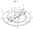
- a flapper check valve 2 is illustrated.
- the check valve 2 is configured to be mounted around its periphery in or to, for example, a duct in order to prevent reverse flow of a fluid through the duct.
- the check valve 2 comprises a valve housing 4, in this embodiment formed as a generally planar annular element.
- the valve housing 4 comprises a pair of valve openings 6 which extend through the body of the valve housing 4 and are separated by a central web 8.
- a pair of mounting posts 10 are arranged on opposed sides of the valve housing 4 and extend upwardly from the valve housing 4.
- a hinge pin 12 is mounted between the mounting posts 10 above the central web 8 of the valve housing 4.
- the valve openings 6 are closed by a pair of generally planar D-shaped flapper elements 14 which are pivotally mounted to the hinge pin 12.
- the flapper elements 14 form a seal with surfaces of the body of the valve housing 4 and the web 8 on one face 15 of the valve housing 4.
- the mounting posts 10 may be integrally formed, for example cast, with the valve housing 4. Alternatively, the mounting posts 10 may be separately formed from the valve housing 4 and mounted thereto by suitable means, for example by welding, brazing or by suitable fastening means.
- a stop pin 16 extends between the mounting posts above the hinge pin 14.
- Bumper elements 18 are arranged opposite one another on the respective flapper elements 14 so as to engage the stop pin 16 when the flapper elements 14 are in the open position.
- Alternative forms of stops may be provided.
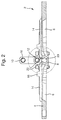
- a check valve of this disclosure further comprises a slot 20 formed in the web 8 through a face 22 thereof on the sealing-side face 15 of the valve housing 4.
- the slot 20 extends along the entire length of the web 8 directly below the hinge pin 12.
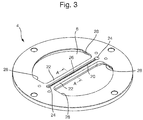
- FIG. 3 shows, in isolation, an embodiment of a valve housing 4 for a check valve 2.
- the slot 20 comprises a medial portion 26 extending between two opposed end portions 24.
- the slot 20 extends along the web 8 from one end portion 24, located at or beyond an edge 28 of an opening 6, to an opposed end portion 24, located at or beyond an opposed edge 28 of the opening 6. It may be beneficial to the structural performance of the web 8 for the larger-diameter end portions to be formed in the more robust area of the valve housing 4 that lies beyond the edges 28 of the openings 6. Alternatively, the slot 20 may only extend to and from locations which lie between the edges 28.
- Figure 4A shows a vertical cross-sectional view of the of valve housing 4 of Figure 3 taken along line A-A of Figure 3 .
- the cross-sectional shape of slot 20 is substantially T-shaped.
- the slot 20 comprises a narrower portion 30 adjacent the face 22 of the web 8 and a wider portion 32 adjacent the narrower portion 30.
- the web 8 further comprises a neutral axis 34.
- the wider portion 32 of the slot 20 is arranged at the neutral axis 34. Removing material from adjacent the neutral axis 34 results in a desirable decrease in mass of the web while minimising the effect on the section modulus of the web 8.
- the illustrated example cross-section further comprises a rounded base 36 in order to reduce stress concentrations in the web 8.
- slot shape described above is merely exemplary, and the slot may have any shape. Some further exemplary slot shapes are illustrated in Figures 4B to 4E .
- the cross-sectional shape of the slot 20 is sized so as to remove as much material as possible without compromising the structural properties of the web 8.
- the slot 20 has a maximum cross-sectional depth that is greater than 15% of the depth of the web 8. In other examples, the depth of the slot 20 is greater than 25%, greater than 50%, or greater than 75% of the web 8 depth. In some embodiments, the maximum cross-sectional width of the slot 20 may be greater than 15% of the width of the web 8. In other examples, the width of the slot 20 is greater than 25%, greater than 50%, or greater than 75% of the web width.
- Figure 4B shows a cross-sectional view of another embodiment of valve housing 4.
- the cross-sectional shape of slot 20 is generally straight, and comprises a single-width portion ending in a rounded base 36.
- Figure 4C shows a cross-sectional view of another embodiment of valve housing 4.
- the cross section of slot 20 comprises a generally T-shaped as in the example of Figure 4A , differing in that the slot 20 comprises a flat base.
- Figure 4D shows a cross-sectional view of another embodiment of valve housing 4.
- the cross-sectional shape of slot 20 is generally straight as in the example of Figure 4B , but comprises a flat base with rounded corners 38.
- Figure 4E shows a cross-sectional view of another embodiment of valve housing 4.
- the cross-sectional shape of slot 20 is generally V-shaped, narrowing towards a flat end of the slot 20.
- the end regions 24 and the medial region 26 may have different cross-sectional shapes.
- the medial portion 26 comprises a generally T-shaped cross-section similar to that illustrated in Figure 4A
- the end regions 24 comprise a generally straight cross-section similar to that illustrated in Figure 4B .
- the narrower portion 30 of the end regions 24 is enlarged relative to the narrower portion 30 of the medial region 26.
- the slot 20 may have the same cross-sectional shape throughout, with no distinct end portions or medial portion.
- Figures 5A to 5C show steps of an example method of forming slot 20 in valve housing 4.
- the exemplary method comprises milling the slot 20 with a milling tool 40.
- Figure 5A shows a side view of the valve housing 4 with milling tool 40.
- the milling tool 40 is first inserted into the web 8 through face 22 to form a first end region 24 of the slot 20.
- the milling tool is then moved along the web 8, following path 42, to form the medial portion 26 of the slot.
- the milling tool 40 is finally withdrawn from web 8 at the end of path 42 to form an opposing end portion 24.
- Figure 5B shows a view of the valve housing 4 taken along line B-B during the milling step.
- Figure 5C shows a view of the valve housing 4 taken along line B-B after the step of milling slot 20.
- the slot 20 may alternatively be formed by other processes, including, but not limited to, casting or additive manufacturing of the valve housing 4.
- the valve housing 4 may be manufactured as part of a new check valve 2. Alternatively, the valve housing 4 may be fitted with other parts from an existing check valve to form a new check valve 2. Thus the valve housing 4 may be used to refurbish or repair an existing check valve by replacing the valve housing of that check valve with a valve housing in accordance with the disclosure.
- Each of the illustrated embodiments has the advantage of minimising the mass of valve housing 4 through the removal of material from the web 8 in the region of its neutral axis 34, while maintaining the structural integrity of the web 8 and the seal between web 8 and flapper elements 14.
Landscapes
- Engineering & Computer Science (AREA)
- General Engineering & Computer Science (AREA)
- Mechanical Engineering (AREA)
- Valve Housings (AREA)
- Check Valves (AREA)
Abstract
Description
- The present disclosure relates to check valves, and in particular to valve housings for check valves.
- It is known to use check valves to allow fluid flow in one direction, and to prevent flow in the opposite direction. Check valves are widely used in a wide variety of applications, for example in air conditioning systems, more particularly in aircraft air conditioning systems.
- Many types of check valves are known. Some check valves include hinged flappers that open in the direction of fluid flow. In such valves, when a fluid pressure exceeds a predetermined valve "cracking pressure", the flappers of the valve open to allow flow through the valve. Likewise, if significant pressure drops in the upstream fluid are experienced (such that there is a negative pressure differential across the valve), the flapper elements close, preventing flow reversal.
- Such valves typically include a valve housing which comprises a pair of valve openings, each sealed by a respective flapper element, and separated by a web. This web has to withstand forces induced by the pressure exerted on the valve.
- It may be desirable to minimise the mass of components, particularly those intended for use in aircraft. To this end, it is desirable to design components to use as little material as possible while meeting structural demands.
- According to one embodiment of the present disclosure, there is provided a valve housing for a check valve, the valve housing comprising a housing body for mounting a pair of flapper elements and a pair of valve openings extending through the valve body. The valve openings are separated by a web which extends from one side of the valve body to an opposed side of the valve body. The valve body and the web define sealing surfaces around the valve openings on one face of the valve housing. The web comprises a slot extending into the web from a face thereof on the one face of the valve housing and extending along a length of the web.
- The slot may have a maximum depth that is greater than 15% of the depth of the web.
- The slot may have a maximum width that is greater than 15% of the width of the web.
- The slot may extend along substantially the entire length of the web.
- The slot may be generally T-shaped in cross section.
- The generally T-shaped cross section may comprise a narrower portion adjacent the one face of the web and a wider portion spaced from the narrower portion.
- The slot may have a rounded base, a flat base, or a flat base with rounded corners.
- According to another embodiment of the present disclosure, there is provided a check valve comprising a valve housing in accordance with the disclosure, and a pair of flapper elements pivotally mounted to the valve housing for closing the valve openings.
- According to another embodiment of the present disclosure, there is provided a method of manufacturing the valve housing in accordance with the disclosure. The method comprises the step of providing a housing body having a pair of valve openings extending therethrough and separated by a web which extends from one side of the valve body to an opposed side of the valve body. The valve body and the web define sealing surfaces around the valve openings on one face of the valve housing. The step further comprises forming a slot extending into the web from a face thereof on the one face of the valve housing.
- The step of forming the slot may comprise milling the slot into the web.
- The milling step may be performed using a milling tool having a generally T-shaped cutting head.
- In a further embodiment, the step of forming the slot may comprise casting the valve housing with the slot in the web.
- In an further embodiment, the step of forming the slot may comprise additively manufacturing the valve housing with the slot in the web.
- According to another embodiment of the present disclosure, there is provided a method of repairing a check valve comprising a valve housing a housing body for mounting a pair of flapper elements. The housing comprises a pair of valve openings extending through said valve body, the valve openings being separated by a web which extends from one side of the valve body to an opposed side of the valve body. The valve body and the web define sealing surfaces around the valve openings on one face of the valve housing. A pair of flapper elements are pivotally mounted to the valve housing for closing the valve openings. The method comprises the step of removing the flapper elements from the valve housing and re-fitting the flapper elements to a valve housing according to the present disclosure.
- Some exemplary embodiments and features of the present disclosure will now be described by way of example only, and with reference to the following drawings in which:
-
Figure 1 shows an isometric view of a check valve in accordance with this disclosure; -
Figure 2 shows a cross-sectional view of the check valve ofFigure 1 ; -
Figure 3 shows a valve housing for a check valve in accordance with this disclosure; -
Figures 4A-4E show example embodiments of cross-sections of valve housings in accordance with this disclosure; -
Figures 5A-5C show a steps in an exemplary method for forming a slot in a valve housing in accordance with this disclosure. - With reference to
Figures 1 and2 , aflapper check valve 2 is illustrated. Thecheck valve 2 is configured to be mounted around its periphery in or to, for example, a duct in order to prevent reverse flow of a fluid through the duct. - The
check valve 2 comprises avalve housing 4, in this embodiment formed as a generally planar annular element. Thevalve housing 4 comprises a pair ofvalve openings 6 which extend through the body of thevalve housing 4 and are separated by acentral web 8. - A pair of
mounting posts 10 are arranged on opposed sides of thevalve housing 4 and extend upwardly from thevalve housing 4. Ahinge pin 12 is mounted between themounting posts 10 above thecentral web 8 of thevalve housing 4. Thevalve openings 6 are closed by a pair of generally planar D-shaped flapper elements 14 which are pivotally mounted to thehinge pin 12. Theflapper elements 14 form a seal with surfaces of the body of thevalve housing 4 and theweb 8 on oneface 15 of thevalve housing 4. - The
mounting posts 10 may be integrally formed, for example cast, with thevalve housing 4. Alternatively, themounting posts 10 may be separately formed from thevalve housing 4 and mounted thereto by suitable means, for example by welding, brazing or by suitable fastening means. - In the illustrated embodiment, a
stop pin 16 extends between the mounting posts above thehinge pin 14.Bumper elements 18 are arranged opposite one another on therespective flapper elements 14 so as to engage thestop pin 16 when theflapper elements 14 are in the open position. Alternative forms of stops may be provided. - As discussed so far, the construction of the
check valve 2 is conventional. - As will now be described with further reference to
Figure 2 and with reference toFigure 3 , a check valve of this disclosure further comprises aslot 20 formed in theweb 8 through aface 22 thereof on the sealing-side face 15 of thevalve housing 4. Theslot 20 extends along the entire length of theweb 8 directly below thehinge pin 12. -
Figure 3 shows, in isolation, an embodiment of avalve housing 4 for acheck valve 2. Theslot 20 comprises amedial portion 26 extending between two opposedend portions 24. In the illustrated non-limiting example, theslot 20 extends along theweb 8 from oneend portion 24, located at or beyond anedge 28 of anopening 6, to anopposed end portion 24, located at or beyond anopposed edge 28 of the opening 6. It may be beneficial to the structural performance of theweb 8 for the larger-diameter end portions to be formed in the more robust area of thevalve housing 4 that lies beyond theedges 28 of theopenings 6. Alternatively, theslot 20 may only extend to and from locations which lie between theedges 28. -
Figure 4A shows a vertical cross-sectional view of the ofvalve housing 4 ofFigure 3 taken along line A-A ofFigure 3 . In this embodiment, the cross-sectional shape ofslot 20 is substantially T-shaped. Theslot 20 comprises anarrower portion 30 adjacent theface 22 of theweb 8 and awider portion 32 adjacent thenarrower portion 30. Theweb 8 further comprises aneutral axis 34. In this example, thewider portion 32 of theslot 20 is arranged at theneutral axis 34. Removing material from adjacent theneutral axis 34 results in a desirable decrease in mass of the web while minimising the effect on the section modulus of theweb 8. The illustrated example cross-section further comprises a roundedbase 36 in order to reduce stress concentrations in theweb 8. - The slot shape described above is merely exemplary, and the slot may have any shape. Some further exemplary slot shapes are illustrated in
Figures 4B to 4E . - In some embodiments, the cross-sectional shape of the
slot 20 is sized so as to remove as much material as possible without compromising the structural properties of theweb 8. In some exemplary embodiments, theslot 20 has a maximum cross-sectional depth that is greater than 15% of the depth of theweb 8. In other examples, the depth of theslot 20 is greater than 25%, greater than 50%, or greater than 75% of theweb 8 depth. In some embodiments, the maximum cross-sectional width of theslot 20 may be greater than 15% of the width of theweb 8. In other examples, the width of theslot 20 is greater than 25%, greater than 50%, or greater than 75% of the web width. -
Figure 4B shows a cross-sectional view of another embodiment ofvalve housing 4. The cross-sectional shape ofslot 20 is generally straight, and comprises a single-width portion ending in arounded base 36. -
Figure 4C shows a cross-sectional view of another embodiment ofvalve housing 4. The cross section ofslot 20 comprises a generally T-shaped as in the example ofFigure 4A , differing in that theslot 20 comprises a flat base. -
Figure 4D shows a cross-sectional view of another embodiment ofvalve housing 4. The cross-sectional shape ofslot 20 is generally straight as in the example ofFigure 4B , but comprises a flat base withrounded corners 38. -
Figure 4E shows a cross-sectional view of another embodiment ofvalve housing 4. The cross-sectional shape ofslot 20 is generally V-shaped, narrowing towards a flat end of theslot 20. - Referring again to
Figure 3 , in one example theend regions 24 and themedial region 26 may have different cross-sectional shapes. In this illustrated example, themedial portion 26 comprises a generally T-shaped cross-section similar to that illustrated inFigure 4A , while theend regions 24 comprise a generally straight cross-section similar to that illustrated inFigure 4B . Thenarrower portion 30 of theend regions 24 is enlarged relative to thenarrower portion 30 of themedial region 26. Alternatively, theslot 20 may have the same cross-sectional shape throughout, with no distinct end portions or medial portion. -
Figures 5A to 5C show steps of an example method of formingslot 20 invalve housing 4. The exemplary method comprises milling theslot 20 with amilling tool 40.Figure 5A shows a side view of thevalve housing 4 withmilling tool 40. As shown, themilling tool 40 is first inserted into theweb 8 throughface 22 to form afirst end region 24 of theslot 20. The milling tool is then moved along theweb 8, followingpath 42, to form themedial portion 26 of the slot. Themilling tool 40 is finally withdrawn fromweb 8 at the end ofpath 42 to form anopposing end portion 24.Figure 5B shows a view of thevalve housing 4 taken along line B-B during the milling step.Figure 5C shows a view of thevalve housing 4 taken along line B-B after the step of millingslot 20. - The
slot 20 may alternatively be formed by other processes, including, but not limited to, casting or additive manufacturing of thevalve housing 4. - The
valve housing 4 may be manufactured as part of anew check valve 2. Alternatively, thevalve housing 4 may be fitted with other parts from an existing check valve to form anew check valve 2. Thus thevalve housing 4 may be used to refurbish or repair an existing check valve by replacing the valve housing of that check valve with a valve housing in accordance with the disclosure. - Each of the illustrated embodiments has the advantage of minimising the mass of
valve housing 4 through the removal of material from theweb 8 in the region of itsneutral axis 34, while maintaining the structural integrity of theweb 8 and the seal betweenweb 8 andflapper elements 14. - Although the figures and the accompanying description describe particular embodiments and examples, it is to be understood that the scope of this disclosure is not to be limited to such specific embodiments, and is, instead, to be determined by the following claims.
Claims (15)
- A valve housing (4) for a check valve (2), said valve housing (4) comprising:a housing body for mounting a pair of flapper elements (14);a pair of valve openings (6) extending through said valve body, said valve openings (6) being separated by a web (8) which extends from one side of the valve body to an opposed side of the valve body;said valve body and said web (8) defining sealing surfaces around the valve openings (6) on one face (15) of the valve housing;wherein the web (8) comprises a slot (20) extending into the web (8) from a face (22) thereof on said one face of said valve housing (4) and extending along a length of the web (8).
- The valve housing (4) of claim 1, wherein the slot (20) has a maximum depth that is greater than 15% of the depth of the web (8).
- The valve housing (4) of claim 1 or 2, wherein the slot (20) has a maximum width that is greater than 15% of the width of the web (8).
- The valve housing (4) of claim 1, 2 or 3, wherein the slot (20) extends along substantially the entire length of the web (8).
- The valve housing (4) of any preceding claim, wherein the slot (20) is generally T-shaped in cross section.
- The valve housing (4) of claim 5, wherein the generally T-shaped cross section comprises a narrower portion (30) adjacent the face (22) of the web (8) and a wider portion (32) spaced from the narrower portion (30).
- The valve housing (4) of any preceding claim, wherein said slot (20) has a rounded base (36), a flat base, or a flat base with rounded corners (38).
- The valve housing (4) of any of claims 1 to 4, wherein said slot (20) is generally V-shaped, and narrows towards the base.
- A check valve (2) comprising:the valve housing (4) of any preceding claim; anda pair of flapper elements (14) pivotally mounted to the valve housing (4) for closing the valve openings (6).
- A method of manufacturing the valve housing (4) of any of claims 1 to 8, the method comprising the step of providing a housing body having a pair of valve openings (6) extending therethrough and separated by a web (8) which extends from one side of the valve body to an opposed side of the valve body said valve body and said web (8) defining sealing surfaces around the valve openings (6) on one face of the valve housing; and
forming a slot (20) extending into the web (8) from a face (22) thereof on said one face of said valve housing. - The method of claim 10, wherein the step of forming the slot (20) comprises milling the slot (20) into the web (8).
- The method of claim 11, wherein said milling is performed using a milling tool (40) having a generally T-shaped cutting head.
- The method of claim 10, wherein the step of forming the slot (20) comprises casting the valve housing (4) with the slot (20) in the web (8).
- The method of claim 10, wherein the step of forming the slot (20) comprises additively manufacturing the valve housing (4) with the slot (20) in the web (8).
- A method of repairing a check valve (2) comprising a valve housing (4) with a housing body for mounting a pair of flapper elements (14);
a pair of valve openings (6) extending through said valve body, said valve openings (6) being separated by a web (8) which extends from one side of the valve body to an opposed side of the valve body;
said valve body and said web (8) defining sealing surfaces around the valve openings on one face of the valve housing (4);
a pair of flapper elements (14) pivotally mounted to the valve housing (4) for closing the valve openings (6); the method comprising:removing the flapper elements (14) from the valve housing (4) and re-fitting the flapper elements (14) to a valve housing (4) of any of claims 1 to 8.
Priority Applications (2)
| Application Number | Priority Date | Filing Date | Title |
|---|---|---|---|
| EP16461526.2A EP3258147B1 (en) | 2016-06-14 | 2016-06-14 | Check valves |
| US15/622,252 US10578224B2 (en) | 2016-06-14 | 2017-06-14 | Check valves |
Applications Claiming Priority (1)
| Application Number | Priority Date | Filing Date | Title |
|---|---|---|---|
| EP16461526.2A EP3258147B1 (en) | 2016-06-14 | 2016-06-14 | Check valves |
Publications (2)
| Publication Number | Publication Date |
|---|---|
| EP3258147A1 true EP3258147A1 (en) | 2017-12-20 |
| EP3258147B1 EP3258147B1 (en) | 2023-07-26 |
Family
ID=56194416
Family Applications (1)
| Application Number | Title | Priority Date | Filing Date |
|---|---|---|---|
| EP16461526.2A Active EP3258147B1 (en) | 2016-06-14 | 2016-06-14 | Check valves |
Country Status (2)
| Country | Link |
|---|---|
| US (1) | US10578224B2 (en) |
| EP (1) | EP3258147B1 (en) |
Families Citing this family (7)
| Publication number | Priority date | Publication date | Assignee | Title |
|---|---|---|---|---|
| EP3181969B1 (en) * | 2015-12-14 | 2019-08-07 | Hamilton Sundstrand Corporation | Check valve |
| US10982851B2 (en) | 2017-09-18 | 2021-04-20 | General Electric Company | Additively manufactured wall and floating ferrule having a frangible member between the floating ferrule and a build support arm |
| US10557555B2 (en) * | 2017-09-18 | 2020-02-11 | General Electric Company | Additively manufactured valve assembly |
| US11156303B2 (en) | 2019-05-31 | 2021-10-26 | Mueller International, Llc | Break check valve for hydrant |
| US11204102B2 (en) | 2020-03-19 | 2021-12-21 | Mueller International, Llc | Watertight check valve |
| EP4083478B1 (en) * | 2021-04-27 | 2024-09-18 | UTC Aerospace Systems Wroclaw Sp. z o.o. | Flapper check valve |
| US11725746B2 (en) * | 2021-06-07 | 2023-08-15 | Mueller International, Llc | Low water hammer break check valve |
Citations (3)
| Publication number | Priority date | Publication date | Assignee | Title |
|---|---|---|---|---|
| US5301709A (en) * | 1993-04-01 | 1994-04-12 | Gulf Valve Company | Check valve and method of assembly |
| US20090235916A1 (en) * | 2008-03-19 | 2009-09-24 | Mind Ag | Non-return valve for an exhaust duct of flue gasses |
| US20120180880A1 (en) * | 2011-01-19 | 2012-07-19 | Cameron International Corporation | Dual plate wafer check valve |
Family Cites Families (7)
| Publication number | Priority date | Publication date | Assignee | Title |
|---|---|---|---|---|
| US1673831A (en) * | 1925-04-29 | 1928-06-19 | Oscar C Kuehne | Valve |
| US1708907A (en) | 1927-04-13 | 1929-04-09 | Spencer Turbine Co | Check valve |
| US4196745A (en) | 1977-04-25 | 1980-04-08 | Gustav F. Gerdts Kg | Flap valve |
| GB9406326D0 (en) * | 1994-03-30 | 1994-05-25 | Goodwin International R Ltd | Fluid check valve |
| KR101525649B1 (en) * | 2009-02-20 | 2015-06-03 | 헨켈 아이피 앤드 홀딩 게엠베하 | Method for connecting electrodes, and connection composition for use in the method |
| CA2889088C (en) * | 2012-10-31 | 2017-09-26 | Makino Milling Machine Co., Ltd. | T-shaped cutter, rib-machining method and airplane part |
| WO2015191960A1 (en) * | 2014-06-13 | 2015-12-17 | Vistadeltek, Llc | High conductance valve for fluids and vapors |
-
2016
- 2016-06-14 EP EP16461526.2A patent/EP3258147B1/en active Active
-
2017
- 2017-06-14 US US15/622,252 patent/US10578224B2/en active Active
Patent Citations (3)
| Publication number | Priority date | Publication date | Assignee | Title |
|---|---|---|---|---|
| US5301709A (en) * | 1993-04-01 | 1994-04-12 | Gulf Valve Company | Check valve and method of assembly |
| US20090235916A1 (en) * | 2008-03-19 | 2009-09-24 | Mind Ag | Non-return valve for an exhaust duct of flue gasses |
| US20120180880A1 (en) * | 2011-01-19 | 2012-07-19 | Cameron International Corporation | Dual plate wafer check valve |
Also Published As
| Publication number | Publication date |
|---|---|
| EP3258147B1 (en) | 2023-07-26 |
| US20170356561A1 (en) | 2017-12-14 |
| US10578224B2 (en) | 2020-03-03 |
Similar Documents
| Publication | Publication Date | Title |
|---|---|---|
| US10578224B2 (en) | Check valves | |
| US5501424A (en) | Wire cutting insert for gate valve | |
| EP1432939B1 (en) | Dispensing valve assembly | |
| CN102481840B (en) | Insert for an opening | |
| JP5896501B2 (en) | Continuous flow equipment and continuous flow method | |
| JP6669018B2 (en) | Oil mist separator | |
| EP3181964B1 (en) | Check valve | |
| EP3220024A1 (en) | Check valve | |
| DE102014110616A1 (en) | Valve housing with valve flap | |
| BR112012009768B1 (en) | VALVE FITTING FOR A MAGNETIC VALVE VALVE CARTRIDGE, VALVE CARTRIDGE FOR A MAGNETIC VALVE, MAGNETIC VALVE AND PROCESS FOR THE PRODUCTION OF A VALVE FITTING | |
| EP1930247A1 (en) | Deaeration valve and compression bag with the deaeration valve | |
| BR102015009701B1 (en) | Flow restrictors and valve assembly | |
| EP1715234A1 (en) | Rotary ball valve assembly | |
| EP3358135B1 (en) | Contouring of a blade row platform | |
| DE102016111232B4 (en) | Diaphragm valve for a vehicle | |
| DE102005059120B3 (en) | Valve device for exhaust return passages has carrier sheet between pressure cavity is with at least one support surface in form of one-piece bent part | |
| EP3156703B1 (en) | Check valve dual-orifice chamfered housing | |
| EP2395216A1 (en) | Flap device for a combustion engine | |
| EP3193054B1 (en) | Check valves | |
| CN108060973B (en) | Air intake device and method for manufacturing valve body | |
| EP3499105B1 (en) | Check valves | |
| DE112009001474T5 (en) | compressor | |
| US10859174B2 (en) | Check valves | |
| JP5886672B2 (en) | Seal structure of valve box division | |
| WO2012092166A1 (en) | Hydraulic flange connection |
Legal Events
| Date | Code | Title | Description |
|---|---|---|---|
| PUAI | Public reference made under article 153(3) epc to a published international application that has entered the european phase |
Free format text: ORIGINAL CODE: 0009012 |
|
| STAA | Information on the status of an ep patent application or granted ep patent |
Free format text: STATUS: THE APPLICATION HAS BEEN PUBLISHED |
|
| AK | Designated contracting states |
Kind code of ref document: A1 Designated state(s): AL AT BE BG CH CY CZ DE DK EE ES FI FR GB GR HR HU IE IS IT LI LT LU LV MC MK MT NL NO PL PT RO RS SE SI SK SM TR |
|
| AX | Request for extension of the european patent |
Extension state: BA ME |
|
| STAA | Information on the status of an ep patent application or granted ep patent |
Free format text: STATUS: REQUEST FOR EXAMINATION WAS MADE |
|
| 17P | Request for examination filed |
Effective date: 20180620 |
|
| RBV | Designated contracting states (corrected) |
Designated state(s): AL AT BE BG CH CY CZ DE DK EE ES FI FR GB GR HR HU IE IS IT LI LT LU LV MC MK MT NL NO PL PT RO RS SE SI SK SM TR |
|
| STAA | Information on the status of an ep patent application or granted ep patent |
Free format text: STATUS: EXAMINATION IS IN PROGRESS |
|
| 17Q | First examination report despatched |
Effective date: 20190812 |
|
| GRAP | Despatch of communication of intention to grant a patent |
Free format text: ORIGINAL CODE: EPIDOSNIGR1 |
|
| STAA | Information on the status of an ep patent application or granted ep patent |
Free format text: STATUS: GRANT OF PATENT IS INTENDED |
|
| INTG | Intention to grant announced |
Effective date: 20230126 |
|
| GRAS | Grant fee paid |
Free format text: ORIGINAL CODE: EPIDOSNIGR3 |
|
| GRAA | (expected) grant |
Free format text: ORIGINAL CODE: 0009210 |
|
| STAA | Information on the status of an ep patent application or granted ep patent |
Free format text: STATUS: THE PATENT HAS BEEN GRANTED |
|
| AK | Designated contracting states |
Kind code of ref document: B1 Designated state(s): AL AT BE BG CH CY CZ DE DK EE ES FI FR GB GR HR HU IE IS IT LI LT LU LV MC MK MT NL NO PL PT RO RS SE SI SK SM TR |
|
| REG | Reference to a national code |
Ref country code: GB Ref legal event code: FG4D |
|
| REG | Reference to a national code |
Ref country code: CH Ref legal event code: EP |
|
| REG | Reference to a national code |
Ref country code: DE Ref legal event code: R096 Ref document number: 602016081321 Country of ref document: DE |
|
| REG | Reference to a national code |
Ref country code: IE Ref legal event code: FG4D |
|
| REG | Reference to a national code |
Ref country code: LT Ref legal event code: MG9D |
|
| REG | Reference to a national code |
Ref country code: NL Ref legal event code: MP Effective date: 20230726 |
|
| REG | Reference to a national code |
Ref country code: AT Ref legal event code: MK05 Ref document number: 1592259 Country of ref document: AT Kind code of ref document: T Effective date: 20230726 |
|
| PG25 | Lapsed in a contracting state [announced via postgrant information from national office to epo] |
Ref country code: NL Free format text: LAPSE BECAUSE OF FAILURE TO SUBMIT A TRANSLATION OF THE DESCRIPTION OR TO PAY THE FEE WITHIN THE PRESCRIBED TIME-LIMIT Effective date: 20230726 |
|
| PG25 | Lapsed in a contracting state [announced via postgrant information from national office to epo] |
Ref country code: GR Free format text: LAPSE BECAUSE OF FAILURE TO SUBMIT A TRANSLATION OF THE DESCRIPTION OR TO PAY THE FEE WITHIN THE PRESCRIBED TIME-LIMIT Effective date: 20231027 |
|
| PG25 | Lapsed in a contracting state [announced via postgrant information from national office to epo] |
Ref country code: IS Free format text: LAPSE BECAUSE OF FAILURE TO SUBMIT A TRANSLATION OF THE DESCRIPTION OR TO PAY THE FEE WITHIN THE PRESCRIBED TIME-LIMIT Effective date: 20231126 |
|
| PG25 | Lapsed in a contracting state [announced via postgrant information from national office to epo] |
Ref country code: SE Free format text: LAPSE BECAUSE OF FAILURE TO SUBMIT A TRANSLATION OF THE DESCRIPTION OR TO PAY THE FEE WITHIN THE PRESCRIBED TIME-LIMIT Effective date: 20230726 Ref country code: RS Free format text: LAPSE BECAUSE OF FAILURE TO SUBMIT A TRANSLATION OF THE DESCRIPTION OR TO PAY THE FEE WITHIN THE PRESCRIBED TIME-LIMIT Effective date: 20230726 Ref country code: PT Free format text: LAPSE BECAUSE OF FAILURE TO SUBMIT A TRANSLATION OF THE DESCRIPTION OR TO PAY THE FEE WITHIN THE PRESCRIBED TIME-LIMIT Effective date: 20231127 Ref country code: NO Free format text: LAPSE BECAUSE OF FAILURE TO SUBMIT A TRANSLATION OF THE DESCRIPTION OR TO PAY THE FEE WITHIN THE PRESCRIBED TIME-LIMIT Effective date: 20231026 Ref country code: LV Free format text: LAPSE BECAUSE OF FAILURE TO SUBMIT A TRANSLATION OF THE DESCRIPTION OR TO PAY THE FEE WITHIN THE PRESCRIBED TIME-LIMIT Effective date: 20230726 Ref country code: LT Free format text: LAPSE BECAUSE OF FAILURE TO SUBMIT A TRANSLATION OF THE DESCRIPTION OR TO PAY THE FEE WITHIN THE PRESCRIBED TIME-LIMIT Effective date: 20230726 Ref country code: IS Free format text: LAPSE BECAUSE OF FAILURE TO SUBMIT A TRANSLATION OF THE DESCRIPTION OR TO PAY THE FEE WITHIN THE PRESCRIBED TIME-LIMIT Effective date: 20231126 Ref country code: HR Free format text: LAPSE BECAUSE OF FAILURE TO SUBMIT A TRANSLATION OF THE DESCRIPTION OR TO PAY THE FEE WITHIN THE PRESCRIBED TIME-LIMIT Effective date: 20230726 Ref country code: GR Free format text: LAPSE BECAUSE OF FAILURE TO SUBMIT A TRANSLATION OF THE DESCRIPTION OR TO PAY THE FEE WITHIN THE PRESCRIBED TIME-LIMIT Effective date: 20231027 Ref country code: FI Free format text: LAPSE BECAUSE OF FAILURE TO SUBMIT A TRANSLATION OF THE DESCRIPTION OR TO PAY THE FEE WITHIN THE PRESCRIBED TIME-LIMIT Effective date: 20230726 Ref country code: AT Free format text: LAPSE BECAUSE OF FAILURE TO SUBMIT A TRANSLATION OF THE DESCRIPTION OR TO PAY THE FEE WITHIN THE PRESCRIBED TIME-LIMIT Effective date: 20230726 |
|
| PG25 | Lapsed in a contracting state [announced via postgrant information from national office to epo] |
Ref country code: PL Free format text: LAPSE BECAUSE OF FAILURE TO SUBMIT A TRANSLATION OF THE DESCRIPTION OR TO PAY THE FEE WITHIN THE PRESCRIBED TIME-LIMIT Effective date: 20230726 |
|
| PG25 | Lapsed in a contracting state [announced via postgrant information from national office to epo] |
Ref country code: ES Free format text: LAPSE BECAUSE OF FAILURE TO SUBMIT A TRANSLATION OF THE DESCRIPTION OR TO PAY THE FEE WITHIN THE PRESCRIBED TIME-LIMIT Effective date: 20230726 |
|
| REG | Reference to a national code |
Ref country code: DE Ref legal event code: R097 Ref document number: 602016081321 Country of ref document: DE |
|
| PG25 | Lapsed in a contracting state [announced via postgrant information from national office to epo] |
Ref country code: SM Free format text: LAPSE BECAUSE OF FAILURE TO SUBMIT A TRANSLATION OF THE DESCRIPTION OR TO PAY THE FEE WITHIN THE PRESCRIBED TIME-LIMIT Effective date: 20230726 Ref country code: RO Free format text: LAPSE BECAUSE OF FAILURE TO SUBMIT A TRANSLATION OF THE DESCRIPTION OR TO PAY THE FEE WITHIN THE PRESCRIBED TIME-LIMIT Effective date: 20230726 Ref country code: ES Free format text: LAPSE BECAUSE OF FAILURE TO SUBMIT A TRANSLATION OF THE DESCRIPTION OR TO PAY THE FEE WITHIN THE PRESCRIBED TIME-LIMIT Effective date: 20230726 Ref country code: EE Free format text: LAPSE BECAUSE OF FAILURE TO SUBMIT A TRANSLATION OF THE DESCRIPTION OR TO PAY THE FEE WITHIN THE PRESCRIBED TIME-LIMIT Effective date: 20230726 Ref country code: DK Free format text: LAPSE BECAUSE OF FAILURE TO SUBMIT A TRANSLATION OF THE DESCRIPTION OR TO PAY THE FEE WITHIN THE PRESCRIBED TIME-LIMIT Effective date: 20230726 Ref country code: CZ Free format text: LAPSE BECAUSE OF FAILURE TO SUBMIT A TRANSLATION OF THE DESCRIPTION OR TO PAY THE FEE WITHIN THE PRESCRIBED TIME-LIMIT Effective date: 20230726 Ref country code: SK Free format text: LAPSE BECAUSE OF FAILURE TO SUBMIT A TRANSLATION OF THE DESCRIPTION OR TO PAY THE FEE WITHIN THE PRESCRIBED TIME-LIMIT Effective date: 20230726 |
|
| PG25 | Lapsed in a contracting state [announced via postgrant information from national office to epo] |
Ref country code: IT Free format text: LAPSE BECAUSE OF FAILURE TO SUBMIT A TRANSLATION OF THE DESCRIPTION OR TO PAY THE FEE WITHIN THE PRESCRIBED TIME-LIMIT Effective date: 20230726 |
|
| PLBE | No opposition filed within time limit |
Free format text: ORIGINAL CODE: 0009261 |
|
| STAA | Information on the status of an ep patent application or granted ep patent |
Free format text: STATUS: NO OPPOSITION FILED WITHIN TIME LIMIT |
|
| 26N | No opposition filed |
Effective date: 20240429 |
|
| PGFP | Annual fee paid to national office [announced via postgrant information from national office to epo] |
Ref country code: GB Payment date: 20240521 Year of fee payment: 9 |
|
| PGFP | Annual fee paid to national office [announced via postgrant information from national office to epo] |
Ref country code: DE Payment date: 20240521 Year of fee payment: 9 |
|
| PG25 | Lapsed in a contracting state [announced via postgrant information from national office to epo] |
Ref country code: SI Free format text: LAPSE BECAUSE OF FAILURE TO SUBMIT A TRANSLATION OF THE DESCRIPTION OR TO PAY THE FEE WITHIN THE PRESCRIBED TIME-LIMIT Effective date: 20230726 |
|
| PGFP | Annual fee paid to national office [announced via postgrant information from national office to epo] |
Ref country code: FR Payment date: 20240522 Year of fee payment: 9 |
|
| PG25 | Lapsed in a contracting state [announced via postgrant information from national office to epo] |
Ref country code: BG Free format text: LAPSE BECAUSE OF FAILURE TO SUBMIT A TRANSLATION OF THE DESCRIPTION OR TO PAY THE FEE WITHIN THE PRESCRIBED TIME-LIMIT Effective date: 20230726 |
|
| PG25 | Lapsed in a contracting state [announced via postgrant information from national office to epo] |
Ref country code: BG Free format text: LAPSE BECAUSE OF FAILURE TO SUBMIT A TRANSLATION OF THE DESCRIPTION OR TO PAY THE FEE WITHIN THE PRESCRIBED TIME-LIMIT Effective date: 20230726 |
|
| PG25 | Lapsed in a contracting state [announced via postgrant information from national office to epo] |
Ref country code: MC Free format text: LAPSE BECAUSE OF FAILURE TO SUBMIT A TRANSLATION OF THE DESCRIPTION OR TO PAY THE FEE WITHIN THE PRESCRIBED TIME-LIMIT Effective date: 20230726 |
|
| REG | Reference to a national code |
Ref country code: CH Ref legal event code: PL |
|
| PG25 | Lapsed in a contracting state [announced via postgrant information from national office to epo] |
Ref country code: LU Free format text: LAPSE BECAUSE OF NON-PAYMENT OF DUE FEES Effective date: 20240614 |
|
| PG25 | Lapsed in a contracting state [announced via postgrant information from national office to epo] |
Ref country code: IE Free format text: LAPSE BECAUSE OF NON-PAYMENT OF DUE FEES Effective date: 20240614 |
|
| PG25 | Lapsed in a contracting state [announced via postgrant information from national office to epo] |
Ref country code: BE Free format text: LAPSE BECAUSE OF NON-PAYMENT OF DUE FEES Effective date: 20240630 Ref country code: CH Free format text: LAPSE BECAUSE OF NON-PAYMENT OF DUE FEES Effective date: 20240630 |
|
| REG | Reference to a national code |
Ref country code: BE Ref legal event code: MM Effective date: 20240630 |
|
| PG25 | Lapsed in a contracting state [announced via postgrant information from national office to epo] |
Ref country code: CY Free format text: LAPSE BECAUSE OF FAILURE TO SUBMIT A TRANSLATION OF THE DESCRIPTION OR TO PAY THE FEE WITHIN THE PRESCRIBED TIME-LIMIT; INVALID AB INITIO Effective date: 20160614 |
|
| REG | Reference to a national code |
Ref country code: DE Ref legal event code: R119 Ref document number: 602016081321 Country of ref document: DE |
|
| GBPC | Gb: european patent ceased through non-payment of renewal fee |
Effective date: 20250614 |
|
| PG25 | Lapsed in a contracting state [announced via postgrant information from national office to epo] |
Ref country code: HU Free format text: LAPSE BECAUSE OF FAILURE TO SUBMIT A TRANSLATION OF THE DESCRIPTION OR TO PAY THE FEE WITHIN THE PRESCRIBED TIME-LIMIT; INVALID AB INITIO Effective date: 20160614 |
|
| PG25 | Lapsed in a contracting state [announced via postgrant information from national office to epo] |
Ref country code: GB Free format text: LAPSE BECAUSE OF NON-PAYMENT OF DUE FEES Effective date: 20250614 |
|
| PG25 | Lapsed in a contracting state [announced via postgrant information from national office to epo] |
Ref country code: DE Free format text: LAPSE BECAUSE OF NON-PAYMENT OF DUE FEES Effective date: 20260101 |
|
| PG25 | Lapsed in a contracting state [announced via postgrant information from national office to epo] |
Ref country code: FR Free format text: LAPSE BECAUSE OF NON-PAYMENT OF DUE FEES Effective date: 20250630 |