EP3258143A1 - Diaphragm for pneumatic controller - Google Patents
Diaphragm for pneumatic controller Download PDFInfo
- Publication number
- EP3258143A1 EP3258143A1 EP17176337.8A EP17176337A EP3258143A1 EP 3258143 A1 EP3258143 A1 EP 3258143A1 EP 17176337 A EP17176337 A EP 17176337A EP 3258143 A1 EP3258143 A1 EP 3258143A1
- Authority
- EP
- European Patent Office
- Prior art keywords
- diaphragm
- pneumatic controller
- diaphragm surface
- piston
- fabric reinforcing
- Prior art date
- Legal status (The legal status is an assumption and is not a legal conclusion. Google has not performed a legal analysis and makes no representation as to the accuracy of the status listed.)
- Granted
Links
Images

Classifications
-
- F—MECHANICAL ENGINEERING; LIGHTING; HEATING; WEAPONS; BLASTING
- F15—FLUID-PRESSURE ACTUATORS; HYDRAULICS OR PNEUMATICS IN GENERAL
- F15B—SYSTEMS ACTING BY MEANS OF FLUIDS IN GENERAL; FLUID-PRESSURE ACTUATORS, e.g. SERVOMOTORS; DETAILS OF FLUID-PRESSURE SYSTEMS, NOT OTHERWISE PROVIDED FOR
- F15B15/00—Fluid-actuated devices for displacing a member from one position to another; Gearing associated therewith
- F15B15/08—Characterised by the construction of the motor unit
- F15B15/10—Characterised by the construction of the motor unit the motor being of diaphragm type
-
- F—MECHANICAL ENGINEERING; LIGHTING; HEATING; WEAPONS; BLASTING
- F16—ENGINEERING ELEMENTS AND UNITS; GENERAL MEASURES FOR PRODUCING AND MAINTAINING EFFECTIVE FUNCTIONING OF MACHINES OR INSTALLATIONS; THERMAL INSULATION IN GENERAL
- F16J—PISTONS; CYLINDERS; SEALINGS
- F16J3/00—Diaphragms; Bellows; Bellows pistons
- F16J3/06—Bellows pistons
-
- F—MECHANICAL ENGINEERING; LIGHTING; HEATING; WEAPONS; BLASTING
- F16—ENGINEERING ELEMENTS AND UNITS; GENERAL MEASURES FOR PRODUCING AND MAINTAINING EFFECTIVE FUNCTIONING OF MACHINES OR INSTALLATIONS; THERMAL INSULATION IN GENERAL
- F16K—VALVES; TAPS; COCKS; ACTUATING-FLOATS; DEVICES FOR VENTING OR AERATING
- F16K31/00—Actuating devices; Operating means; Releasing devices
- F16K31/12—Actuating devices; Operating means; Releasing devices actuated by fluid
- F16K31/126—Actuating devices; Operating means; Releasing devices actuated by fluid the fluid acting on a diaphragm, bellows, or the like
Definitions
- the subject matter disclosed herein relates to pneumatic systems, and more particularly to pneumatic controllers.
- Pneumatic controllers typically are configured with a housing including two abutting chambers, separated from each other via a diaphragm, diaphragm plate and a piston.
- the diaphragm and piston are movable in the housing in response to pressure differences between the two chambers.
- a spring is located in the housing to bias the position if the piston, and is supported by a spring seat positioned in the housing.
- a bolt extends through the spring seat and piston to fix the relationship of the components.
- a diaphragm is positioned between the spring seat and the piston.
- the bolt stack up between the diaphragm, piston and spring seat can loosen as a result of the diaphragm compressing.
- This compression also known as "creep" of the diaphragm, results in a calibration of the controller shifting to outside of predetermined acceptable calibration limits.
- a collar is incorporated in the bolt stack, extending through a diaphragm opening, through which the bolt also extends.
- the diaphragm opening is enlarged, resulting in a loss of strength of the diaphragm. The loss of strength can lead to rupture of the diaphragm and loss of function of the controller.
- a pneumatic controller in one embodiment, includes a housing, a piston located in the housing and movable therein and a diaphragm located at the piston to isolate a first chamber of the pneumatic controller from a second chamber of the pneumatic controller.
- the diaphragm includes a first diaphragm surface, a diaphragm opening extending through the diaphragm, and a fabric reinforcing layer to strengthen the diaphragm.
- the pneumatic controller includes a spring seat positioned at the piston and a spring operably connected to the spring seat to bias a position of the piston.
- the diaphragm is located between the piston and the spring seat.
- the fabric reinforcing layer is disposed at the first diaphragm surface.
- the fabric reinforcing layer covers an entirety of the first diaphragm surface.
- a second diaphragm surface is located opposite the first diaphragm surface.
- a fabric reinforcing layer is positioned at the second diaphragm surface.
- a second diaphragm surface is located opposite the first diaphragm surface and the fabric reinforcing layer is positioned between the first diaphragm surface and the second diaphragm surface.
- two fabric reinforcing layers are located between the first diaphragm surface and the second diaphragm surface.
- the two fabric reinforcing layers are of unequal size.
- the fabric reinforcing layer is integrally molded into the diaphragm.
- the fabric reinforcing layer is formed from a high temperature resistant material.
- a diaphragm to isolate a first chamber of a pneumatic controller from a second chamber of a pneumatic controller includes a first diaphragm surface, a diaphragm opening extending through the diaphragm, and a fabric reinforcing layer to strengthen the diaphragm.
- the fabric reinforcing layer is located at the first diaphragm surface.
- the fabric reinforcing layer covers an entirety of the first diaphragm surface.
- the fabric reinforcing layer covers between 25% and 75% of the first diaphragm surface.
- a second diaphragm surface is located opposite the first diaphragm surface, and a fabric reinforcing layer is located at the second diaphragm surface.
- a second diaphragm surface is located opposite the first diaphragm surface and the fabric reinforcing layer is located between the first diaphragm surface and the second diaphragm surface.
- two fabric reinforcing layers are located between the first diaphragm surface and the second diaphragm surface.
- the fabric reinforcing layer is formed from a high temperature resistant material.
- the fabric reinforcing layer is integrally molded into the diaphragm.
- a pneumatic controller in yet another embodiment, includes a housing, a piston located in the housing and movable therein, a spring seat located at the piston, a spring operably connected to the spring seat to bias a position of the piston, a bolt extending through the spring seat into the piston to secure the spring seat to the piston, and a diaphragm interposed between the piston and the spring seat to isolate a first chamber of the pneumatic controller from a second chamber of the pneumatic controller.
- the diaphragm includes a first diaphragm surface, a diaphragm opening extending through the diaphragm, the bolt extending through the diaphragm opening, and a fabric reinforcing layer to strengthen the diaphragm.
- a collar is located at the spring seat and extends through the diaphragm opening.
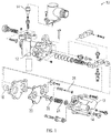
- FIG. 1 Shown in FIG. 1 is an exploded view of an embodiment of a pneumatic controller 10.
- the controller 10 includes a housing 12 with pneumatic ports 14 to pressurize an interior of the housing 12.
- a piston 16 is located in the housing 12, and a diaphragm 30, dividing the interior into a first chamber 18 and a second chamber 20, as shown in FIG. 2 .
- the piston 16 is movable in the housing 12 in response to a pressure difference between a first chamber 18 pressure and a second chamber 20 pressure.
- the piston 16 is biased in a direction along a piston axis 22 by a biasing member, for example, a spring 24.
- the spring 24 is interactive with the piston 16 via a spring seat 26 located between the spring 24 and the piston 16.
- the spring seat 26 is fixed to the piston 16 via a bolt 28 or other mechanical fastener, such as a screw or rod extending through both the piston 16 and the spring seat 26.
- a diaphragm 30 is positioned between the spring seat 26 and the piston 16 to isolate the first chamber 18 from the second chamber 20.
- the diaphragm 30 is formed from, for example, silicone, an elastomer material such as a rubber, or other material such that the diaphragm seals to the housing 12 to isolate the first chamber 18 from the second chamber 20.
- the diaphragm 30 includes a diaphragm opening 32 through which the bolt 28 extends.
- a collar 34 is located at the diaphragm opening 32 to prevent movement or "creep" of the diaphragm 30 in an axial direction 36 in the event that the forces retaining the spring seat 26 at the piston 16 reduce over the service life of the controller 10. For example, the bolt 28 may loosen due to creep resulting in a reduction of retention forces.
- the collar 34 is integral to the spring seat 26.
- the diaphragm 30 is reinforced to improve strength of the diaphragm 30, increasing a burst pressure of the diaphragm 30 while still accommodating the collar 34.
- the reinforcement is in the form of one or more reinforcing fabric layers 38 located at the diaphragm 30.
- the one or more fabric layers 38 are formed from a high temperature resistant fabric such as Nomex®, for use in applications where the operating temperature exceeds 300 degrees Fahrenheit.
- the one or more fabric layers 38 are located between the diaphragm 30 and the spring seat 26, and/or between the diaphragm 30 and the piston 16.
- the one or more fabric layers 38 are integrally molded into the diaphragm 30 or are alternatively secured to the diaphragm by, for example, an adhesive bond or other means.
- a first fabric layer 38 extends through the diaphragm in its entirety, while a second fabric layer 38 is an annular piece located at the spring seat 26.
- the fabric layers 38 may be located at outer surfaces of the diaphragm 30, and may completely cover the diaphragm 30 surface, while in other embodiments, such as shown in FIG. 5 , the fabric layer 38 may only partially cover the diaphragm 30 surface.
- the fabric layer 38 covers a portion of the diaphragm 30 surface centered on the diaphragm opening 32 corresponding to between 25% and 75% of the diaphragm 30 surface area.
- the reinforcement fabric layers 38 located at the diaphragm 30 strengthen the diaphragm to aid in resisting rupture of the diaphragm. Further, the fabric layers 38 add creep resistance to the diaphragm, thus aiding the pneumatic controller in staying within predetermined calibration limits during its operational life.
Landscapes
- Engineering & Computer Science (AREA)
- General Engineering & Computer Science (AREA)
- Mechanical Engineering (AREA)
- Physics & Mathematics (AREA)
- Fluid Mechanics (AREA)
- Diaphragms And Bellows (AREA)
Abstract
Description
- The subject matter disclosed herein relates to pneumatic systems, and more particularly to pneumatic controllers.
- Pneumatic controllers typically are configured with a housing including two abutting chambers, separated from each other via a diaphragm, diaphragm plate and a piston. The diaphragm and piston are movable in the housing in response to pressure differences between the two chambers. A spring is located in the housing to bias the position if the piston, and is supported by a spring seat positioned in the housing. A bolt extends through the spring seat and piston to fix the relationship of the components. To aid in sealing between the chambers, a diaphragm is positioned between the spring seat and the piston.
- Over the service life of the controller, the bolt stack up between the diaphragm, piston and spring seat can loosen as a result of the diaphragm compressing. This compression also known as "creep" of the diaphragm, results in a calibration of the controller shifting to outside of predetermined acceptable calibration limits. To prevent the diaphragm creep, a collar is incorporated in the bolt stack, extending through a diaphragm opening, through which the bolt also extends. To accommodate the collar, however, the diaphragm opening is enlarged, resulting in a loss of strength of the diaphragm. The loss of strength can lead to rupture of the diaphragm and loss of function of the controller.
- In one embodiment, a pneumatic controller includes a housing, a piston located in the housing and movable therein and a diaphragm located at the piston to isolate a first chamber of the pneumatic controller from a second chamber of the pneumatic controller. The diaphragm includes a first diaphragm surface, a diaphragm opening extending through the diaphragm, and a fabric reinforcing layer to strengthen the diaphragm.
- Additionally or alternatively, in this or other embodiments the pneumatic controller includes a spring seat positioned at the piston and a spring operably connected to the spring seat to bias a position of the piston. The diaphragm is located between the piston and the spring seat.
- Additionally or alternatively, in this or other embodiments the fabric reinforcing layer is disposed at the first diaphragm surface.
- Additionally or alternatively, in this or other embodiments the fabric reinforcing layer covers an entirety of the first diaphragm surface.
- Additionally or alternatively, in this or other embodiments a second diaphragm surface is located opposite the first diaphragm surface. A fabric reinforcing layer is positioned at the second diaphragm surface.
- Additionally or alternatively, in this or other embodiments a second diaphragm surface is located opposite the first diaphragm surface and the fabric reinforcing layer is positioned between the first diaphragm surface and the second diaphragm surface.
- Additionally or alternatively, in this or other embodiments two fabric reinforcing layers are located between the first diaphragm surface and the second diaphragm surface.
- Additionally or alternatively, in this or other embodiments the two fabric reinforcing layers are of unequal size.
- Additionally or alternatively, in this or other embodiments the fabric reinforcing layer is integrally molded into the diaphragm.
- Additionally or alternatively, in this or other embodiments the fabric reinforcing layer is formed from a high temperature resistant material.
- In another embodiment, a diaphragm to isolate a first chamber of a pneumatic controller from a second chamber of a pneumatic controller includes a first diaphragm surface, a diaphragm opening extending through the diaphragm, and a fabric reinforcing layer to strengthen the diaphragm.
- Additionally or alternatively, in this or other embodiments the fabric reinforcing layer is located at the first diaphragm surface.
- Additionally or alternatively, in this or other embodiments the fabric reinforcing layer covers an entirety of the first diaphragm surface.
- Additionally or alternatively, in this or other embodiments the fabric reinforcing layer covers between 25% and 75% of the first diaphragm surface.
- Additionally or alternatively, in this or other embodiments a second diaphragm surface is located opposite the first diaphragm surface, and a fabric reinforcing layer is located at the second diaphragm surface.
- Additionally or alternatively, in this or other embodiments a second diaphragm surface is located opposite the first diaphragm surface and the fabric reinforcing layer is located between the first diaphragm surface and the second diaphragm surface.
- Additionally or alternatively, in this or other embodiments two fabric reinforcing layers are located between the first diaphragm surface and the second diaphragm surface.
- Additionally or alternatively, in this or other embodiments the fabric reinforcing layer is formed from a high temperature resistant material.
- Additionally or alternatively, in this or other embodiments the fabric reinforcing layer is integrally molded into the diaphragm.
- In yet another embodiment, a pneumatic controller includes a housing, a piston located in the housing and movable therein, a spring seat located at the piston, a spring operably connected to the spring seat to bias a position of the piston, a bolt extending through the spring seat into the piston to secure the spring seat to the piston, and a diaphragm interposed between the piston and the spring seat to isolate a first chamber of the pneumatic controller from a second chamber of the pneumatic controller. The diaphragm includes a first diaphragm surface, a diaphragm opening extending through the diaphragm, the bolt extending through the diaphragm opening, and a fabric reinforcing layer to strengthen the diaphragm. A collar is located at the spring seat and extends through the diaphragm opening.
- The subject matter is particularly pointed out and distinctly claimed at the conclusion of the specification. The foregoing and other features, and advantages of the present disclosure are apparent from the following detailed description taken in conjunction with the accompanying drawings in which:
-
FIG. 1 is an exploded view of an embodiment of a pneumatic controller; -
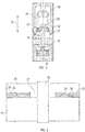
FIG. 2 is a cross-sectional view of an embodiment of a bolt stack of a pneumatic controller; -
FIG. 3 is another cross-sectional view of a bolt stack of a pneumatic controller including a diaphragm; -
FIG. 4 is a cross-sectional view of another embodiment of a bolt stack of a pneumatic controller including a diaphragm; and -
FIG. 5 is a cross-sectional view of yet another embodiment of a bolt stack of a pneumatic controller including a diaphragm. - Shown in
FIG. 1 is an exploded view of an embodiment of apneumatic controller 10. Thecontroller 10 includes ahousing 12 withpneumatic ports 14 to pressurize an interior of thehousing 12. Apiston 16 is located in thehousing 12, and adiaphragm 30, dividing the interior into afirst chamber 18 and asecond chamber 20, as shown inFIG. 2 . Thepiston 16 is movable in thehousing 12 in response to a pressure difference between afirst chamber 18 pressure and asecond chamber 20 pressure. - Referring to
FIG. 2 , thepiston 16 is biased in a direction along apiston axis 22 by a biasing member, for example, aspring 24. Thespring 24 is interactive with thepiston 16 via aspring seat 26 located between thespring 24 and thepiston 16. Thespring seat 26 is fixed to thepiston 16 via abolt 28 or other mechanical fastener, such as a screw or rod extending through both thepiston 16 and thespring seat 26. - A
diaphragm 30 is positioned between thespring seat 26 and thepiston 16 to isolate thefirst chamber 18 from thesecond chamber 20. Thediaphragm 30 is formed from, for example, silicone, an elastomer material such as a rubber, or other material such that the diaphragm seals to thehousing 12 to isolate thefirst chamber 18 from thesecond chamber 20. Thediaphragm 30 includes a diaphragm opening 32 through which thebolt 28 extends. In some embodiments, acollar 34 is located at the diaphragm opening 32 to prevent movement or "creep" of thediaphragm 30 in anaxial direction 36 in the event that the forces retaining thespring seat 26 at thepiston 16 reduce over the service life of thecontroller 10. For example, thebolt 28 may loosen due to creep resulting in a reduction of retention forces. In some embodiments, such as shown inFIG. 2 , thecollar 34 is integral to thespring seat 26. - Referring now to
FIG. 3 , thediaphragm 30 is reinforced to improve strength of thediaphragm 30, increasing a burst pressure of thediaphragm 30 while still accommodating thecollar 34. The reinforcement is in the form of one or more reinforcingfabric layers 38 located at thediaphragm 30. In some embodiments, the one ormore fabric layers 38 are formed from a high temperature resistant fabric such as Nomex®, for use in applications where the operating temperature exceeds 300 degrees Fahrenheit. As shown inFIG. 3 , in some embodiments, the one ormore fabric layers 38 are located between thediaphragm 30 and thespring seat 26, and/or between thediaphragm 30 and thepiston 16. The one ormore fabric layers 38 are integrally molded into thediaphragm 30 or are alternatively secured to the diaphragm by, for example, an adhesive bond or other means. In the embodiment ofFIG. 3 , afirst fabric layer 38 extends through the diaphragm in its entirety, while asecond fabric layer 38 is an annular piece located at thespring seat 26. - Further, in some embodiments, such as shown in
FIG. 4 , the fabric layers 38 may be located at outer surfaces of thediaphragm 30, and may completely cover thediaphragm 30 surface, while in other embodiments, such as shown inFIG. 5 , thefabric layer 38 may only partially cover thediaphragm 30 surface. For example, in some embodiments thefabric layer 38 covers a portion of thediaphragm 30 surface centered on thediaphragm opening 32 corresponding to between 25% and 75% of thediaphragm 30 surface area. - The reinforcement fabric layers 38 located at the
diaphragm 30 strengthen the diaphragm to aid in resisting rupture of the diaphragm. Further, the fabric layers 38 add creep resistance to the diaphragm, thus aiding the pneumatic controller in staying within predetermined calibration limits during its operational life. - While the present disclosure has been described in detail in connection with only a limited number of embodiments, it should be readily understood that the present disclosure is not limited to such disclosed embodiments. Rather, the present disclosure can be modified to incorporate any number of variations, alterations, substitutions or equivalent arrangements not heretofore described, but which are commensurate in spirit and/or scope. Additionally, while various embodiments have been described, it is to be understood that aspects of the present disclosure may include only some of the described embodiments. Accordingly, the present disclosure is not to be seen as limited by the foregoing description, but is only limited by the scope of the appended claims.
Claims (15)
- A diaphragm (30) to isolate a first chamber (18) of a pneumatic controller (10) from a second chamber (20) of a pneumatic controller (10) comprising:a first diaphragm surface;a diaphragm opening (32) extending through the diaphragm (30); anda fabric reinforcing layer (38) to strengthen the diaphragm.
- The diaphragm of claim 1, wherein the fabric reinforcing layer is disposed at the first diaphragm surface.
- The diaphragm of claim 2, further comprising a second diaphragm surface opposite the first diaphragm surface, a fabric reinforcing layer disposed at the second diaphragm surface.
- The diaphragm of any preceding claim, further comprising a second diaphragm surface opposite the first diaphragm surface, the fabric reinforcing layer disposed between the first diaphragm surface and the second diaphragm surface.
- The diaphragm of claim 4, further comprising two fabric reinforcing layers (38) disposed between the first diaphragm surface and the second diaphragm surface.
- A pneumatic controller (10), comprising:a housing (12);a piston (16) disposed in the housing (12) and movable therein;the diaphragm (30) of any preceding claim disposed at the piston (16) to isolate said first chamber (18) of the pneumatic controller (10) from said second chamber (20) of the pneumatic controller (10).
- The pneumatic controller of claim 6, further comprising:a spring seat (26) disposed at the piston (16); anda spring (24) operably connected to the spring seat (26) to bias a position of the piston (16);wherein the diaphragm (30) is disposed between the piston (16) and the spring seat (26).
- The pneumatic controller of claim 6 or 7, wherein the fabric reinforcing layer (38) is disposed at the first diaphragm surface.
- The pneumatic controller of claim 8, wherein the fabric reinforcing layer (38) covers an entirety of the first diaphragm surface.
- The pneumatic controller of claim 8, further comprising a second diaphragm surface opposite the first diaphragm surface, a fabric reinforcing layer (38) disposed at the second diaphragm surface.
- The pneumatic controller of any of claims 6 to 10, further comprising a second diaphragm surface opposite the first diaphragm surface, the fabric reinforcing layer (38) disposed between the first diaphragm surface and the second diaphragm surface.
- The pneumatic controller of claim 11, further comprising two fabric reinforcing layers (38) disposed between the first diaphragm surface and the second diaphragm surface.
- The pneumatic controller of claim 12 wherein the two fabric reinforcing layers (38) are of unequal size.
- The pneumatic controller of claim 11, wherein the fabric reinforcing layer (38) is integrally molded into the diaphragm.
- The pneumatic controller of any of claims 6 to 14, wherein the fabric reinforcing layer (38) is formed from a high temperature resistant material.
Applications Claiming Priority (1)
| Application Number | Priority Date | Filing Date | Title |
|---|---|---|---|
| US15/185,112 US10371177B2 (en) | 2016-06-17 | 2016-06-17 | Diaphragm for pneumatic controller |
Publications (2)
| Publication Number | Publication Date |
|---|---|
| EP3258143A1 true EP3258143A1 (en) | 2017-12-20 |
| EP3258143B1 EP3258143B1 (en) | 2022-06-08 |
Family
ID=59227468
Family Applications (1)
| Application Number | Title | Priority Date | Filing Date |
|---|---|---|---|
| EP17176337.8A Active EP3258143B1 (en) | 2016-06-17 | 2017-06-16 | Diaphragm for pneumatic controller |
Country Status (2)
| Country | Link |
|---|---|
| US (1) | US10371177B2 (en) |
| EP (1) | EP3258143B1 (en) |
Citations (3)
| Publication number | Priority date | Publication date | Assignee | Title |
|---|---|---|---|---|
| EP1481170B1 (en) * | 2002-03-06 | 2006-06-14 | Honeywell International Inc. | Pneumatic actuator with diaphragms having aligned fabric patterns |
| EP2153986A2 (en) * | 2003-11-13 | 2010-02-17 | Fisher Controls International Llc | Housing comprising resin coated flanges and a diaphragm comprising a rubber composition and a plasticizer |
| EP2363610A1 (en) * | 2010-03-04 | 2011-09-07 | smk systeme metall kunststoff gmbh & co. kg. | Pneumatic adjuster |
Family Cites Families (7)
| Publication number | Priority date | Publication date | Assignee | Title |
|---|---|---|---|---|
| US2905199A (en) * | 1953-12-28 | 1959-09-22 | Westinghouse Air Brake Co | Fluid pressure actuator |
| US3026909A (en) | 1959-03-27 | 1962-03-27 | Grinnell Corp | Reinforced diaphragm |
| US3310280A (en) | 1965-11-16 | 1967-03-21 | Grinnell Corp | Diaphragm valve |
| US4014514A (en) | 1975-06-27 | 1977-03-29 | Hills-Mccanna Company | High pressure diaphragm valve |
| DE7538274U (en) * | 1975-12-01 | 1976-04-08 | Kempken, Hans, 5210 Troisdorf | COMPRESSED AIR FLAT CUSHIONS |
| US4050358A (en) * | 1976-09-22 | 1977-09-27 | Harbor Products, Inc. | Diaphragm and method of making |
| US5836233A (en) | 1997-03-07 | 1998-11-17 | Rumsey; Donald | Spring brake with sealable breather holes |
-
2016
- 2016-06-17 US US15/185,112 patent/US10371177B2/en active Active
-
2017
- 2017-06-16 EP EP17176337.8A patent/EP3258143B1/en active Active
Patent Citations (3)
| Publication number | Priority date | Publication date | Assignee | Title |
|---|---|---|---|---|
| EP1481170B1 (en) * | 2002-03-06 | 2006-06-14 | Honeywell International Inc. | Pneumatic actuator with diaphragms having aligned fabric patterns |
| EP2153986A2 (en) * | 2003-11-13 | 2010-02-17 | Fisher Controls International Llc | Housing comprising resin coated flanges and a diaphragm comprising a rubber composition and a plasticizer |
| EP2363610A1 (en) * | 2010-03-04 | 2011-09-07 | smk systeme metall kunststoff gmbh & co. kg. | Pneumatic adjuster |
Also Published As
| Publication number | Publication date |
|---|---|
| US10371177B2 (en) | 2019-08-06 |
| US20170363118A1 (en) | 2017-12-21 |
| EP3258143B1 (en) | 2022-06-08 |
Similar Documents
| Publication | Publication Date | Title |
|---|---|---|
| KR102840353B1 (en) | Vent with relief valve | |
| US10164227B2 (en) | Degassing valve | |
| US9638345B2 (en) | Valve apparatus | |
| EP3569921B1 (en) | Poppet type pneumatic valve for inflation system | |
| US10549740B2 (en) | Pressure-limiting valve | |
| JP6395696B2 (en) | Control valve for variable displacement compressor | |
| JP2018534499A (en) | Pressure limiting valve | |
| US20200300380A1 (en) | Inflation electric valve with manual override | |
| JP2018506463A (en) | Compressed air supply device for vehicle compressed air equipment, comprising at least one housing made of plastic | |
| CN112654768A (en) | Valve device | |
| JP6346907B2 (en) | Overflow valve | |
| US10006558B2 (en) | Pilot-operated solenoid valve | |
| EP1623146B1 (en) | O-ring forming sealing washer | |
| US9796256B2 (en) | Controllable hydraulic vibration-damping supports | |
| AU2017210484B2 (en) | Valve | |
| US10371177B2 (en) | Diaphragm for pneumatic controller | |
| WO2014152310A1 (en) | Pressure relief valve assembly | |
| US20170346359A1 (en) | Air pressure adjuster for rotary electric machine | |
| US2777029A (en) | Fluid actuated switch | |
| JP2017227308A (en) | Gas pressure reducing valve | |
| JP6395940B2 (en) | Compressed media device with variable flow connection based on molded seal | |
| JP6100550B2 (en) | Pressure control valve | |
| JP5302504B2 (en) | Multi-protection valve | |
| CN115004867A (en) | Housing with pressure balancing device | |
| JP5847899B1 (en) | High pressure gas seal |
Legal Events
| Date | Code | Title | Description |
|---|---|---|---|
| PUAI | Public reference made under article 153(3) epc to a published international application that has entered the european phase |
Free format text: ORIGINAL CODE: 0009012 |
|
| STAA | Information on the status of an ep patent application or granted ep patent |
Free format text: STATUS: THE APPLICATION HAS BEEN PUBLISHED |
|
| AK | Designated contracting states |
Kind code of ref document: A1 Designated state(s): AL AT BE BG CH CY CZ DE DK EE ES FI FR GB GR HR HU IE IS IT LI LT LU LV MC MK MT NL NO PL PT RO RS SE SI SK SM TR |
|
| AX | Request for extension of the european patent |
Extension state: BA ME |
|
| RIN1 | Information on inventor provided before grant (corrected) |
Inventor name: DEFELICE, ROBERT Inventor name: FAASS, ADAM |
|
| STAA | Information on the status of an ep patent application or granted ep patent |
Free format text: STATUS: REQUEST FOR EXAMINATION WAS MADE |
|
| 17P | Request for examination filed |
Effective date: 20180620 |
|
| RBV | Designated contracting states (corrected) |
Designated state(s): AL AT BE BG CH CY CZ DE DK EE ES FI FR GB GR HR HU IE IS IT LI LT LU LV MC MK MT NL NO PL PT RO RS SE SI SK SM TR |
|
| STAA | Information on the status of an ep patent application or granted ep patent |
Free format text: STATUS: EXAMINATION IS IN PROGRESS |
|
| 17Q | First examination report despatched |
Effective date: 20191112 |
|
| GRAP | Despatch of communication of intention to grant a patent |
Free format text: ORIGINAL CODE: EPIDOSNIGR1 |
|
| STAA | Information on the status of an ep patent application or granted ep patent |
Free format text: STATUS: GRANT OF PATENT IS INTENDED |
|
| INTG | Intention to grant announced |
Effective date: 20220119 |
|
| RAP3 | Party data changed (applicant data changed or rights of an application transferred) |
Owner name: HAMILTON SUNDSTRAND CORPORATION |
|
| GRAS | Grant fee paid |
Free format text: ORIGINAL CODE: EPIDOSNIGR3 |
|
| GRAA | (expected) grant |
Free format text: ORIGINAL CODE: 0009210 |
|
| STAA | Information on the status of an ep patent application or granted ep patent |
Free format text: STATUS: THE PATENT HAS BEEN GRANTED |
|
| AK | Designated contracting states |
Kind code of ref document: B1 Designated state(s): AL AT BE BG CH CY CZ DE DK EE ES FI FR GB GR HR HU IE IS IT LI LT LU LV MC MK MT NL NO PL PT RO RS SE SI SK SM TR |
|
| REG | Reference to a national code |
Ref country code: AT Ref legal event code: REF Ref document number: 1497146 Country of ref document: AT Kind code of ref document: T Effective date: 20220615 Ref country code: CH Ref legal event code: EP |
|
| REG | Reference to a national code |
Ref country code: DE Ref legal event code: R096 Ref document number: 602017058226 Country of ref document: DE |
|
| REG | Reference to a national code |
Ref country code: IE Ref legal event code: FG4D |
|
| REG | Reference to a national code |
Ref country code: LT Ref legal event code: MG9D |
|
| REG | Reference to a national code |
Ref country code: NL Ref legal event code: MP Effective date: 20220608 |
|
| PG25 | Lapsed in a contracting state [announced via postgrant information from national office to epo] |
Ref country code: SE Free format text: LAPSE BECAUSE OF FAILURE TO SUBMIT A TRANSLATION OF THE DESCRIPTION OR TO PAY THE FEE WITHIN THE PRESCRIBED TIME-LIMIT Effective date: 20220608 Ref country code: NO Free format text: LAPSE BECAUSE OF FAILURE TO SUBMIT A TRANSLATION OF THE DESCRIPTION OR TO PAY THE FEE WITHIN THE PRESCRIBED TIME-LIMIT Effective date: 20220908 Ref country code: LT Free format text: LAPSE BECAUSE OF FAILURE TO SUBMIT A TRANSLATION OF THE DESCRIPTION OR TO PAY THE FEE WITHIN THE PRESCRIBED TIME-LIMIT Effective date: 20220608 Ref country code: HR Free format text: LAPSE BECAUSE OF FAILURE TO SUBMIT A TRANSLATION OF THE DESCRIPTION OR TO PAY THE FEE WITHIN THE PRESCRIBED TIME-LIMIT Effective date: 20220608 Ref country code: GR Free format text: LAPSE BECAUSE OF FAILURE TO SUBMIT A TRANSLATION OF THE DESCRIPTION OR TO PAY THE FEE WITHIN THE PRESCRIBED TIME-LIMIT Effective date: 20220909 Ref country code: FI Free format text: LAPSE BECAUSE OF FAILURE TO SUBMIT A TRANSLATION OF THE DESCRIPTION OR TO PAY THE FEE WITHIN THE PRESCRIBED TIME-LIMIT Effective date: 20220608 Ref country code: BG Free format text: LAPSE BECAUSE OF FAILURE TO SUBMIT A TRANSLATION OF THE DESCRIPTION OR TO PAY THE FEE WITHIN THE PRESCRIBED TIME-LIMIT Effective date: 20220908 |
|
| REG | Reference to a national code |
Ref country code: AT Ref legal event code: MK05 Ref document number: 1497146 Country of ref document: AT Kind code of ref document: T Effective date: 20220608 |
|
| PG25 | Lapsed in a contracting state [announced via postgrant information from national office to epo] |
Ref country code: RS Free format text: LAPSE BECAUSE OF FAILURE TO SUBMIT A TRANSLATION OF THE DESCRIPTION OR TO PAY THE FEE WITHIN THE PRESCRIBED TIME-LIMIT Effective date: 20220608 Ref country code: LV Free format text: LAPSE BECAUSE OF FAILURE TO SUBMIT A TRANSLATION OF THE DESCRIPTION OR TO PAY THE FEE WITHIN THE PRESCRIBED TIME-LIMIT Effective date: 20220608 |
|
| PG25 | Lapsed in a contracting state [announced via postgrant information from national office to epo] |
Ref country code: NL Free format text: LAPSE BECAUSE OF FAILURE TO SUBMIT A TRANSLATION OF THE DESCRIPTION OR TO PAY THE FEE WITHIN THE PRESCRIBED TIME-LIMIT Effective date: 20220608 |
|
| REG | Reference to a national code |
Ref country code: DE Ref legal event code: R119 Ref document number: 602017058226 Country of ref document: DE |
|
| PG25 | Lapsed in a contracting state [announced via postgrant information from national office to epo] |
Ref country code: SM Free format text: LAPSE BECAUSE OF FAILURE TO SUBMIT A TRANSLATION OF THE DESCRIPTION OR TO PAY THE FEE WITHIN THE PRESCRIBED TIME-LIMIT Effective date: 20220608 Ref country code: SK Free format text: LAPSE BECAUSE OF FAILURE TO SUBMIT A TRANSLATION OF THE DESCRIPTION OR TO PAY THE FEE WITHIN THE PRESCRIBED TIME-LIMIT Effective date: 20220608 Ref country code: RO Free format text: LAPSE BECAUSE OF FAILURE TO SUBMIT A TRANSLATION OF THE DESCRIPTION OR TO PAY THE FEE WITHIN THE PRESCRIBED TIME-LIMIT Effective date: 20220608 Ref country code: PT Free format text: LAPSE BECAUSE OF FAILURE TO SUBMIT A TRANSLATION OF THE DESCRIPTION OR TO PAY THE FEE WITHIN THE PRESCRIBED TIME-LIMIT Effective date: 20221010 Ref country code: ES Free format text: LAPSE BECAUSE OF FAILURE TO SUBMIT A TRANSLATION OF THE DESCRIPTION OR TO PAY THE FEE WITHIN THE PRESCRIBED TIME-LIMIT Effective date: 20220608 Ref country code: EE Free format text: LAPSE BECAUSE OF FAILURE TO SUBMIT A TRANSLATION OF THE DESCRIPTION OR TO PAY THE FEE WITHIN THE PRESCRIBED TIME-LIMIT Effective date: 20220608 Ref country code: CZ Free format text: LAPSE BECAUSE OF FAILURE TO SUBMIT A TRANSLATION OF THE DESCRIPTION OR TO PAY THE FEE WITHIN THE PRESCRIBED TIME-LIMIT Effective date: 20220608 Ref country code: AT Free format text: LAPSE BECAUSE OF FAILURE TO SUBMIT A TRANSLATION OF THE DESCRIPTION OR TO PAY THE FEE WITHIN THE PRESCRIBED TIME-LIMIT Effective date: 20220608 |
|
| REG | Reference to a national code |
Ref country code: CH Ref legal event code: PL |
|
| REG | Reference to a national code |
Ref country code: BE Ref legal event code: MM Effective date: 20220630 |
|
| PG25 | Lapsed in a contracting state [announced via postgrant information from national office to epo] |
Ref country code: PL Free format text: LAPSE BECAUSE OF FAILURE TO SUBMIT A TRANSLATION OF THE DESCRIPTION OR TO PAY THE FEE WITHIN THE PRESCRIBED TIME-LIMIT Effective date: 20220608 Ref country code: IS Free format text: LAPSE BECAUSE OF FAILURE TO SUBMIT A TRANSLATION OF THE DESCRIPTION OR TO PAY THE FEE WITHIN THE PRESCRIBED TIME-LIMIT Effective date: 20221008 |
|
| PG25 | Lapsed in a contracting state [announced via postgrant information from national office to epo] |
Ref country code: MC Free format text: LAPSE BECAUSE OF FAILURE TO SUBMIT A TRANSLATION OF THE DESCRIPTION OR TO PAY THE FEE WITHIN THE PRESCRIBED TIME-LIMIT Effective date: 20220608 Ref country code: AL Free format text: LAPSE BECAUSE OF FAILURE TO SUBMIT A TRANSLATION OF THE DESCRIPTION OR TO PAY THE FEE WITHIN THE PRESCRIBED TIME-LIMIT Effective date: 20220608 |
|
| PLBE | No opposition filed within time limit |
Free format text: ORIGINAL CODE: 0009261 |
|
| STAA | Information on the status of an ep patent application or granted ep patent |
Free format text: STATUS: NO OPPOSITION FILED WITHIN TIME LIMIT |
|
| PG25 | Lapsed in a contracting state [announced via postgrant information from national office to epo] |
Ref country code: LU Free format text: LAPSE BECAUSE OF NON-PAYMENT OF DUE FEES Effective date: 20220616 Ref country code: LI Free format text: LAPSE BECAUSE OF NON-PAYMENT OF DUE FEES Effective date: 20220630 Ref country code: IE Free format text: LAPSE BECAUSE OF NON-PAYMENT OF DUE FEES Effective date: 20220616 Ref country code: DK Free format text: LAPSE BECAUSE OF FAILURE TO SUBMIT A TRANSLATION OF THE DESCRIPTION OR TO PAY THE FEE WITHIN THE PRESCRIBED TIME-LIMIT Effective date: 20220608 Ref country code: CH Free format text: LAPSE BECAUSE OF NON-PAYMENT OF DUE FEES Effective date: 20220630 |
|
| 26N | No opposition filed |
Effective date: 20230310 |
|
| PG25 | Lapsed in a contracting state [announced via postgrant information from national office to epo] |
Ref country code: SI Free format text: LAPSE BECAUSE OF FAILURE TO SUBMIT A TRANSLATION OF THE DESCRIPTION OR TO PAY THE FEE WITHIN THE PRESCRIBED TIME-LIMIT Effective date: 20220608 Ref country code: DE Free format text: LAPSE BECAUSE OF NON-PAYMENT OF DUE FEES Effective date: 20230103 Ref country code: BE Free format text: LAPSE BECAUSE OF NON-PAYMENT OF DUE FEES Effective date: 20220630 |
|
| P01 | Opt-out of the competence of the unified patent court (upc) registered |
Effective date: 20230522 |
|
| PG25 | Lapsed in a contracting state [announced via postgrant information from national office to epo] |
Ref country code: IT Free format text: LAPSE BECAUSE OF FAILURE TO SUBMIT A TRANSLATION OF THE DESCRIPTION OR TO PAY THE FEE WITHIN THE PRESCRIBED TIME-LIMIT Effective date: 20220608 |
|
| PG25 | Lapsed in a contracting state [announced via postgrant information from national office to epo] |
Ref country code: HU Free format text: LAPSE BECAUSE OF FAILURE TO SUBMIT A TRANSLATION OF THE DESCRIPTION OR TO PAY THE FEE WITHIN THE PRESCRIBED TIME-LIMIT; INVALID AB INITIO Effective date: 20170616 |
|
| PG25 | Lapsed in a contracting state [announced via postgrant information from national office to epo] |
Ref country code: MK Free format text: LAPSE BECAUSE OF FAILURE TO SUBMIT A TRANSLATION OF THE DESCRIPTION OR TO PAY THE FEE WITHIN THE PRESCRIBED TIME-LIMIT Effective date: 20220608 Ref country code: CY Free format text: LAPSE BECAUSE OF FAILURE TO SUBMIT A TRANSLATION OF THE DESCRIPTION OR TO PAY THE FEE WITHIN THE PRESCRIBED TIME-LIMIT Effective date: 20220608 |
|
| PG25 | Lapsed in a contracting state [announced via postgrant information from national office to epo] |
Ref country code: MT Free format text: LAPSE BECAUSE OF FAILURE TO SUBMIT A TRANSLATION OF THE DESCRIPTION OR TO PAY THE FEE WITHIN THE PRESCRIBED TIME-LIMIT Effective date: 20220608 |
|
| PG25 | Lapsed in a contracting state [announced via postgrant information from national office to epo] |
Ref country code: BG Free format text: LAPSE BECAUSE OF FAILURE TO SUBMIT A TRANSLATION OF THE DESCRIPTION OR TO PAY THE FEE WITHIN THE PRESCRIBED TIME-LIMIT Effective date: 20220608 |
|
| PG25 | Lapsed in a contracting state [announced via postgrant information from national office to epo] |
Ref country code: BG Free format text: LAPSE BECAUSE OF FAILURE TO SUBMIT A TRANSLATION OF THE DESCRIPTION OR TO PAY THE FEE WITHIN THE PRESCRIBED TIME-LIMIT Effective date: 20220608 |
|
| PGFP | Annual fee paid to national office [announced via postgrant information from national office to epo] |
Ref country code: GB Payment date: 20250520 Year of fee payment: 9 |
|
| PGFP | Annual fee paid to national office [announced via postgrant information from national office to epo] |
Ref country code: FR Payment date: 20250520 Year of fee payment: 9 |
|
| PG25 | Lapsed in a contracting state [announced via postgrant information from national office to epo] |
Ref country code: TR Free format text: LAPSE BECAUSE OF FAILURE TO SUBMIT A TRANSLATION OF THE DESCRIPTION OR TO PAY THE FEE WITHIN THE PRESCRIBED TIME-LIMIT Effective date: 20220608 |