EP3258078A1 - Système de refroidissement d'un moteur thermique - Google Patents
Système de refroidissement d'un moteur thermique Download PDFInfo
- Publication number
- EP3258078A1 EP3258078A1 EP17175805.5A EP17175805A EP3258078A1 EP 3258078 A1 EP3258078 A1 EP 3258078A1 EP 17175805 A EP17175805 A EP 17175805A EP 3258078 A1 EP3258078 A1 EP 3258078A1
- Authority
- EP
- European Patent Office
- Prior art keywords
- circuit
- engine
- cooling system
- cylinder block
- cylinder head
- Prior art date
- Legal status (The legal status is an assumption and is not a legal conclusion. Google has not performed a legal analysis and makes no representation as to the accuracy of the status listed.)
- Granted
Links
Images

Classifications
-
- F—MECHANICAL ENGINEERING; LIGHTING; HEATING; WEAPONS; BLASTING
- F01—MACHINES OR ENGINES IN GENERAL; ENGINE PLANTS IN GENERAL; STEAM ENGINES
- F01P—COOLING OF MACHINES OR ENGINES IN GENERAL; COOLING OF INTERNAL-COMBUSTION ENGINES
- F01P3/00—Liquid cooling
- F01P3/02—Arrangements for cooling cylinders or cylinder heads
-
- F—MECHANICAL ENGINEERING; LIGHTING; HEATING; WEAPONS; BLASTING
- F01—MACHINES OR ENGINES IN GENERAL; ENGINE PLANTS IN GENERAL; STEAM ENGINES
- F01P—COOLING OF MACHINES OR ENGINES IN GENERAL; COOLING OF INTERNAL-COMBUSTION ENGINES
- F01P3/00—Liquid cooling
- F01P3/02—Arrangements for cooling cylinders or cylinder heads
- F01P2003/027—Cooling cylinders and cylinder heads in parallel
-
- F—MECHANICAL ENGINEERING; LIGHTING; HEATING; WEAPONS; BLASTING
- F01—MACHINES OR ENGINES IN GENERAL; ENGINE PLANTS IN GENERAL; STEAM ENGINES
- F01P—COOLING OF MACHINES OR ENGINES IN GENERAL; COOLING OF INTERNAL-COMBUSTION ENGINES
- F01P7/00—Controlling of coolant flow
- F01P7/14—Controlling of coolant flow the coolant being liquid
- F01P2007/146—Controlling of coolant flow the coolant being liquid using valves
Definitions
- the present invention relates to a cooling system of a heat engine.
- the invention also relates to a heat engine comprising such a cooling system and a method of manufacturing such a motor.
- the invention also relates to a vehicle including a motor vehicle comprising such a motor.
- a heat engine usually comprises a cylinder block closed by a cylinder head.
- these housings must be cooled.
- the engine is provided with a cooling system in which a coolant is circulated by means of a feed pump and which, in turn, is cooled through a radiator.
- the operating temperature of an engine is normally much higher than the outside temperature, especially in cold weather. Any startup of the latter is therefore accompanied by a preheating phase during which the performance is not optimal, especially during which the emissions of pollutants of carbon monoxide and unburnt hydrocarbons are much larger than nominal .
- low load engine operating phases with temperature regulation may also require a particular cooling strategy to optimize engine performance.
- the state of the art is known to include a motor provided with a a so-called double-cooling cooling system, otherwise known as split-cooling, in which the coolant circulates independently in a first and a second fluid circuit respectively of the cylinder block and the cylinder head; flow in the first fluid circuit being established once the preheating phase is completed and during severe thermal stresses of the motor from an activation of a valve arranged at the output of this first circuit.
- a so-called double-cooling cooling system otherwise known as split-cooling
- Such a system makes it possible, among other things, to minimize the heating time of the engine or a part of it, by accelerating the rise in temperature of the coolant at the start of the vehicle, with a view to reducing piston friction. and segments in engine drums, fuel consumption and pollutant emissions.
- one of the disadvantages of such a cooling system is related to the fact that it does not allow to achieve optimum and efficient cooling of the engine and in particular the cylinder head.
- This system is therefore hardly compatible with an engine having high levels of specific power, for example with an engine having a specific power greater than 100 kW per liter of displacement.
- the prior art discloses a cooling system 101 of the double-cooling type of a motor 100 illustrated in FIGS. Figures 1 and 2 , in which the coolant circulates independently in a first and a second fluid circuit 105, 104 respectively of the cylinder block 102 and the cylinder head 103.
- This system 101 comprises a heat transfer fluid distribution chamber 106 to the second circuit 104 of fluid defined in the cylinder head 103 and which makes it possible to achieve a transverse circulation of the coolant through the cylinder head 103 at the combustion face including the bridges defined on this face.
- This distribution chamber 106 which is connected as input to a pump power supply 107 is conventionally arranged at an outer face 108 of the motor 100.
- such a motor 100 provided with a cooling system 101 comprising the distribution chamber 106 arranged at this outer face 108 has a size that is not suitable for the engine compartment of today's vehicles. Indeed, car manufacturers and / or engine manufacturers are currently seeking to achieve in view of the dimensions of such compartments, increasingly compact engines and nevertheless have improved performance in terms of power and / or performance that often involve an increase thermal stresses at the level of these.
- the present invention aims to overcome these disadvantages related to the state of the art.
- the invention makes it possible to reduce the bulk of a motor with a high specific power provided with a cooling system, in particular of the double-cooling type.
- the invention contributes to simplifying and reducing the cost of a method of manufacturing an engine comprising such a cooling system.
- the invention relates to a cooling system, in particular of the double cooling type, of a thermal engine of a motor vehicle comprising first and second heat transfer fluid circuits respectively defined in a crankcase and a cylinder head of said engine. , the system comprising a distribution chamber arranged in the first circuit for supplying the second fluid circuit.
- the invention also relates to a particular thermal engine comprising an open tablature type crankcase having such a cooling system.
- the step of producing a distribution chamber comprises a substep of arranging a separating element in a first part of the first circuit.
- the invention also relates to a motor vehicle comprising such a heat engine.
- the figure 3 is a schematic representation of an embodiment of a cooling system 2 of a heat engine 1 of a motor vehicle.
- This engine 1 may be a gasoline engine or a diesel engine including supercharged or a motor 1 operating using a technology known as "Flex Fuel” and whose fuel system and carburetion allows it to use indifferently fuels as varied as gasoline, bioethanol or a mixture of both.
- the cooling system 2 is implemented in a motor 1 having high levels of specific power.
- This system 2 can comprise a main circuit 3 provided with components of the engine 1 such as a degassing jar 24, a supercharging module of the engine 1 comprising a turbocharger 25, a heat exchanger 26 such as a heater or at a oil exchanger 27.
- such a motor 1 comprises a cylinder block 5a provided with a plurality of cylinders 21 which can be stored in line.
- This crankcase 5a is preferably of the "open tablature" type, better known by the English term "open deck”.
- Above the cylinder block 5a along an axis substantially parallel to the vertical axis of the cylinders 21, is fixed the cylinder head 5b.
- This cylinder head 5b includes the distribution mainly composed of valves and camshafts.
- This yoke 5b also comprises a lower face otherwise called combustion face or fire face which is intended to be fixed on an upper face of the cylinder block 5a, which being disposed below this yoke 5b.
- This combustion face defines a combustion chamber of the cylinders 21 of the engine 1.
- the cylinder head comprises exhaust ducts 17a and intake ducts 17b each opening into the combustion chamber and which are respectively equipped with exhaust valves and intake.
- the exhaust ducts 17a or admission 17b are separated by a relatively narrow zone 19 called "bridge".
- the bridges 19 are located in the part of the cylinder head 5b subjected to the highest temperatures, especially for the parts of these bridges 19 located between the exhaust ducts 17a.
- these bridges 19 are subjected to heating and cooling cycles with each cycle of operation of the engine 1. These are fragile zones, more heated than the surrounding areas which are more massive and here in this embodiment of the invention. the invention better cooled during operation of the engine 1.
- the yoke 5b may also include an integrated exhaust manifold provided with a cavity, or plenum, into which open first ends of the exhaust ducts 17a whose second ends are connected to the combustion chambers of the engine 1 .
- This engine 1 also comprises a cylinder head gasket 36 placed between the cylinder head 5b and the cylinder block 5a and in particular between the above-mentioned upper and lower faces.
- This cylinder head gasket 36 participates in a hermetic connection between the cylinder block 5a and the cylinder head 5b.
- the main circuit 3 of this system 2 comprises an internal cooling circuit 4 inside the engine 1 which is provided with: a pump supply 14, first and second fluid circuits 6a, 6b and a distribution chamber 7 for supplying the second fluid circuit 6b.
- the feed pump 14 is intended to circulate the heat transfer fluid still called cooling fluid in this internal cooling circuit 4 of the engine 1.
- the first and second circuits 6a, 6b are respectively included in the crankcase 5a and the cylinder head 5b. These first and second circuits 6a, 6b otherwise called core or fluid chamber each comprise a hollow space or a recess constituted by circulation channels which is defined in the crankcase 5a or the cylinder head 5b of the engine 1 and in which is intended to circulate.
- this cooling fluid here water or ethylene glycol with or without adjuvants.
- the second circuit 6b is also defined in the exhaust manifold 20 integrated with the cylinder head 5b.
- the first circuit 6a comprises first and second parts 9a, 9b.
- the first part 9a extends longitudinally along one side of a row of cylinders 21 of the cylinder block 5a.
- This first portion 9a comprises upper and lower compartments 7, 8 sealed and separated by a separating element 22 visible on the figure 6 .
- the upper compartment 7 is defined at an upper portion of the cylinder block 5a and is about one-quarter of the volume of this first portion 9a of the first circuit 6a.
- the lower compartment 8 it is defined between a bottom of this first part 9a of the first circuit 6a and the separating element 22. It represents about three quarters of the volume of this first part 9a of the first circuit 6a.
- the separating element 22 is preferably an insert in the first part 9a of the first circuit 6a of the cylinder block 5a after its manufacture. This separating element 22 extends longitudinally preferably over the entire length of this first part 9a along the side of the row of cylinders 21 of the cylinder block 5a.
- This separation element 22 may be an insert or a plate which is preferably rigid and is made of a material having high thermal resistance properties such as plastic or a composite material.
- the system 2 comprises a third circuit 6c comprising the lower compartment 8 and the second part 9b of the first circuit 6a.
- this third circuit 6c corresponds to the first circuit 6a devoid of the upper compartment 7.
- this third circuit 6c is defined in the cylinder block 5a and is intended to ensure a longitudinal circulation of the coolant along the opposite sides of a row of cylinders 21 of the engine 1 in the direction of the dotted arrows F1 illustrated on the figure 5 and / or a transverse circulation of the coolant through the cylinder block 5a in particular between the cylinders 21 of the engine 1 in the direction of the dashed arrows F2 illustrated on this figure 5 .
- This third circuit 6c comprises an input 10a corresponding to an input of the lower compartment 8 which is connected to the supply pump 14 of the system 2.
- the third circuit 6c comprises an output 10b corresponding to an output of the second part 9b of the first circuit 6a which is connected to a fluid flow control element 13 in this third circuit 6c.
- This regulation element 13 is defined to allow / prohibit a circulation of the heat transfer fluid in the third circuit 6c as a function of a temperature of said fluid present in the third circuit 6c of said cylinder block 5a.
- This regulating element 13 may be a thermostat provided with a temperature sensor immersed in the heat transfer fluid present in this third circuit 6c or watered by this fluid. It may be a temperature sensor included in the body of the thermostat or a remote sensor arranged in this third circuit 6c.
- This thermostat may for example be a wax thermostat comprising two flaps arranged at both ends of a wax bulb and whose operation is well known in the state of the art.
- this regulation element 13 may be a valve driven for example by a processing unit of the system 2 which is connected to a sensor of temperature located in the third circuit 6c.
- the regulating element 13 comprises an outlet which is connected to a fluid outlet housing 15 or "Water Outlet Box", better known by the acronym BSE.
- This housing 15 which is fixed to the engine 1, and preferably to the cylinder head 5b of the engine 1, ensures the collection of the heat transfer fluid circulated in the internal circuit 4 of the engine 1 and in particular in the second and third circuits 6b, 6c and only in the distribution chamber 7.
- the distribution chamber 7 is arranged in the first circuit 6a and is provided for supplying the second circuit 6b with fluid.
- This distribution chamber 7 corresponds to the upper compartment 7 of the first circuit 6a.
- the chamber 7 comprises a bottom wall forming the bottom of this chamber 7 corresponding to the separating element 22, and an opening formed in the upper face of the cylinder block 5a and which is covered by a portion of the cylinder head gasket 36 when the assembly of this cylinder block 5a with the cylinder head 5b and this cylinder head gasket 36.
- This portion of the cylinder head gasket 36 which is arranged at the upper compartment 7 is provided with orifices 18, on the figure 4 this embodiment comprises three.
- the distribution chamber 7 extends longitudinally along one side of a row of cylinders 21 of the cylinder block 5a and this, at an upper portion of the cylinder block 5a.
- the distribution chamber 7 comprises an inlet 11a connected to the feed pump 14 and an outlet 11b connected to an inlet 12a of the second circuit 6b.
- the coolant included in the distribution chamber 7 is circulated by the feed pump 14 so as to pass through the orifices 18 of the cylinder head gasket 36 and circulate in the second circuit 6b.
- the latter ensures a transverse circulation of the fluid through the cylinder head 5b in the direction of the arrows F3 at the combustion face including the bridge 19 defined on this face.
- the cooling fluid is able to circulate at the bridges 19 of the combustion face between the exhaust ducts 17a and 17b intake.
- the second circuit 6b is able to ensure also a longitudinal circulation of the coolant in the direction of the arrows F4 along at least one side of the combustion face of the cylinder head 5b.
- This second circuit 6b includes an output 12b which is connected to the fluid outlet housing 15.
- the system 2 also comprises a fluid inlet duct 16a of the internal circuit 4 connected in particular to an output of a radiator 23 but also to component outputs of the motor 1 mentioned above.
- This inlet duct 16a comprises the supply pump 14 provided with an outlet connected directly and distinctly to the inlet 11a of the distribution chamber 7 at the upper compartment 7 and at the inlet 10a of the third circuit 6c ie at the lower compartment 8.
- the feed pump 14 contributes to circulating the heat transfer fluid that it receives in particular from this radiator and / or the components of the engine 1, in the third circuit 6c and the second circuit 6b via the distribution chamber 7.
- the fluid outlet housing 15 is in turn connected to a discharge pipe 16b of fluid of the internal circuit 4.
- This exhaust duct 16b is then in particular connected to the radiator inlets and other components of the engine 1 so that the heat transfer fluid is transmitted to them according to the activation / deactivation of a valve 28 or a thermostat 28 arranged in the main cooling circuit 3.
- This radiator 23 which is included in the main circuit 3, constitutes a heat exchanger for cooling the heat transfer fluid at the outlet of the internal circuit 4 at the level of the evacuation duct 16b.
- the radiator 23 is then able to return the cooled heat transfer fluid to the internal circuit 4 via the inlet duct 16a provided with the feed pump 14.
- the cooling system 2 of the double cooling type often known by the Anglo-Saxon term “split-cooling" and in which the heat transfer fluid circulates independently in the third circuit 6c which is defined in the crankcase 5a and the second circuit 6b included in the cylinder head 5b, the circulation in the third circuit 6c being established only once a preheating phase of the cylinder block 5a is completed by the activation of the regulation element 13.
- the heat transfer fluid is circulated in the internal circuit 4 from the feed pump 14 whose output is connected to the inputs 10a, 11a of the third and second circuits 6c, 6b.
- the flow of the coolant in the third circuit 6c is controlled to implement a preheating process of the engine and thus improve the performance of the latter while reducing pollutant emissions and fuel consumption.
- the regulation element 13 then prohibits the circulation of this heat transfer fluid in the third circuit 6c when a temperature of the fluid present in this circuit 6c is substantially lower than a reference temperature.
- the temperature of the fluid can be estimated or measured.
- This reference temperature is defined according to the characteristics of the engine 1 and preferably corresponds to a preheating end temperature of the crankcase 5a.
- the control element 13 allows the flow of fluid in the third circuit 6c. Under these conditions, the heat transfer fluid circulated by the feed pump 13 flows in both the third and second circuits 6c, 6b.
- the invention also relates to a method of manufacturing the engine 1 in particular comprising the casing 5a of the open tablature type, comprising this cooling system 2.
- This method comprises a step 29 for obtaining the cylinder block 5a and the cylinder head 5b respectively comprising the first and second heat transfer fluid circuits 6a, 6b.
- This obtaining step 29 implements processes for manufacturing the cylinder block 5a and the cylinder head 5b, in particular from molding, foundry and / or machining processes well known in the state of the art.
- the molding manufacturing process can for example provide for the use of permanent molds (metal) or destructible molds (sand mold or resorbable salt mold).
- This method then comprises a step 30 of producing the distribution chamber 7 in the first circuit 6a, said chamber 7 being provided for supplying the second circuit 6b with heat transfer fluid.
- This step 30 comprises an arrangement sub-step 31 of a separating element 22 in the first part 9a of the first circuit 6a extending longitudinally along one side of a row of cylinders 21 of the cylinder block 5a.
- the method comprises an assembly step 32 of the crankcase 5a with the cylinder head 5b.
- This step 32 comprises a sub-step 33 of fixing the lower face of the cylinder head 5b with the upper face of the cylinder block 5a, and an insertion sub-step 34 of the cylinder head gasket 36 between these lower and upper faces.
- the part of the cylinder head gasket 36 which is provided with the orifices 18 is then positioned at the opening of the upper compartment 7 included in the upper face of the cylinder block 5a located in the first part 9a of the first circuit 6a.
- the method also comprises a step of mounting the operating components of the engine 1 and the cooling system 2 in / on the engine 1.
- These operating components of the engine 1 correspond, for example, in a nonlimiting and non-exhaustive manner to the components and components. dispensing and / or driving the engine 1.
- the invention makes it possible to reduce the size of a motor 1, in particular of an engine having a high specific power, and which is provided with the cooling system 2, in particular of the double-cooling type.
- the invention makes it possible to ensure optimum and efficient cooling at the bridges 19 between the exhaust ducts 17a and 17b of admission, which makes it possible to improve the heat exchanges in this zone and to limit the risks of boiling of the cooling fluid.
- the engine 1 and in particular the yoke 5b have excellent thermomechanical behavior to prevent any risk of crack or crack initiation.
- Such a motor is then more compact lighter and more economical to achieve.
Landscapes
- Engineering & Computer Science (AREA)
- Chemical & Material Sciences (AREA)
- Combustion & Propulsion (AREA)
- Mechanical Engineering (AREA)
- General Engineering & Computer Science (AREA)
- Cylinder Crankcases Of Internal Combustion Engines (AREA)
- Cooling, Air Intake And Gas Exhaust, And Fuel Tank Arrangements In Propulsion Units (AREA)
Abstract
Description
- La présente invention concerne un système de refroidissement d'un moteur thermique.
- L'invention concerne également un moteur thermique comprenant un tel système de refroidissement ainsi qu'un procédé de fabrication d'un tel moteur.
- L'invention concerne aussi un véhicule notamment un véhicule automobile comportant un tel moteur.
- Dans l'état de la technique, un moteur thermique comporte habituellement un carter cylindres fermé par une culasse. Pour le bon fonctionnement du moteur, ces carters doivent être refroidis. Pour ce faire, le moteur est muni d'un système de refroidissement dans lequel un fluide caloporteur est mis en circulation au moyen d'une pompe d'alimentation et qui, à son tour, est refroidi en traversant un radiateur.
- Pour autant, la température de fonctionnement d'un moteur est normalement bien supérieure à la température extérieure, en particulier par temps froid. Tout démarrage de ce dernier s'accompagne donc d'une phase de préchauffage pendant laquelle les performances ne sont pas optimales, en particulier pendant laquelle les émissions de polluants de monoxyde de carbone et hydrocarbures imbrûlés sont en quantité beaucoup plus importante qu'en régime nominal.
- De même, les phases de fonctionnement du moteur en faible charge avec une régulation de température peuvent nécessiter également une stratégie de refroidissement particulière afin d'optimiser les performances du moteur.
- Pour optimiser le refroidissement du moteur selon différentes phases de fonctionnement, on connaît dans l'état de la technique un moteur pourvu d'un système de refroidissement dit à double refroidissement autrement appelés sous le terme anglo-saxon de « split-cooling », dans lequel le fluide caloporteur circule de façon indépendante dans un premier et un deuxième circuit de fluide respectivement du carter cylindres et de la culasse, la circulation dans le premier circuit de fluide étant établie une fois la phase de préchauffage achevée et lors de sollicitations thermiques importantes du moteur à partir d'une activation d'une vanne agencée en sortie de ce premier circuit.
- Un tel système permet entre autres de minimiser le temps de chauffe du moteur ou d'une partie de celui-ci, en accélérant la montée en température du fluide caloporteur au démarrage du véhicule et ce, dans l'optique de réduire des frottements de pistons et de segments dans des fûts du moteur, la consommation de carburant et les émissions polluantes.
- Toutefois, un des inconvénients d'un tel système de refroidissement est lié au fait qu'il ne permet pas de réaliser un refroidissement optimal et efficace du moteur et notamment de la culasse. Ce système est donc de fait difficilement compatible avec un moteur présentant de forts niveaux de puissance spécifique par exemple avec un moteur ayant une puissance spécifique supérieure à 100 kW par litre de cylindrée.
- Pour pallier cet inconvénient, on connaît dans l'état de la technique un système de refroidissement 101 du type à double refroidissement d'un moteur 100 illustré sur les
figures 1 et 2 , dans lequel le fluide caloporteur circule de façon indépendante dans un premier et un deuxième circuit 105, 104 de fluide respectivement du carter cylindres 102 et de la culasse 103. Ce système 101 comprend une chambre de distribution 106 du fluide caloporteur au deuxième circuit 104 de fluide défini dans la culasse 103 et qui permet de réaliser une circulation transversale du fluide caloporteur au travers de la culasse 103 au niveau de la face de combustion notamment des pontets définis sur cette face. Cette chambre de distribution 106 qui est reliée en entrée à une pompe d'alimentation 107 est classiquement agencée au niveau d'une face externe 108 du moteur 100. - Cependant, un tel moteur 100 pourvu d'un système de refroidissement 101 comprenant cette chambre de distribution 106 agencée au niveau de cette face extérieure 108 présente un encombrement qui n'est pas adapté au compartiment moteur des véhicules d'aujourd'hui. En effet, les constructeurs automobiles et/ou les motoristes cherchent actuellement à réaliser au vue des dimensions de tels compartiments, des moteurs de plus en plus compacts et présentant néanmoins des performances améliorées en terme de puissance et/ou de rendement qui impliquent souvent un accroissement de contraintes thermiques au niveau de ces derniers.
- La présente invention vise à pallier ces inconvénients liés à l'état de la technique.
- Avantageusement, l'invention permet de réduire l'encombrement d'un moteur à forte puissance spécifique pourvu de système de refroidissement notamment du type à double refroidissement.
- En particulier, l'invention contribue à simplifier et réduire le coût d'un procédé de fabrication d'un moteur comprenant un tel système de refroidissement.
- Dans ce dessein, l'invention porte sur un système de refroidissement notamment du type à double refroidissement, d'un moteur thermique d'un véhicule automobile comprenant des premier et deuxième circuits de fluide caloporteur définis respectivement dans un carter cylindres et une culasse dudit moteur, le système comportant une chambre de distribution agencée dans le premier circuit prévue pour alimenter le deuxième circuit en fluide.
- Dans d'autres modes de réalisation :
- ladite chambre de distribution correspond à un compartiment supérieur d'une première partie du premier circuit comprenant des compartiments supérieur et inférieur séparés par un élément de séparation ;
- une première partie du premier circuit s'étend longitudinalement le long d'un côté d'une rangée de cylindres du carter cylindres ;
- la chambre de distribution comprend une entrée reliée à une pompe d'alimentation et une sortie reliée à une entrée du deuxième circuit ;
- le système comprend un troisième circuit assurant :
- ▪ une circulation longitudinale du fluide caloporteur au travers du carter cylindres le long de côtés opposés d'une rangée de cylindres du moteur ;
- ▪ une circulation transversale du fluide caloporteur au travers du carter cylindres notamment entre les cylindres du moteur ;
- le deuxième circuit est défini dans la culasse et assure :
- ▪ une circulation transversale du fluide caloporteur au travers de la culasse au niveau d'au moins une face de combustion notamment d'un pontet défini sur cette face ;
- ▪ une circulation longitudinale du fluide caloporteur le long d'au moins un côté d'une face de combustion de la culasse ;
- un troisième circuit comprend un compartiment inférieur d'une première partie du premier circuit et une deuxième partie du premier circuit défini dans le carter cylindres ;
- un troisième circuit comprend une entrée correspondant à une entrée du compartiment inférieur qui est reliée à une pompe d'alimentation du système ;
- un troisième circuit comprend une sortie correspondant à une sortie d'une deuxième partie du premier circuit qui est reliée à un élément de régulation du débit de fluide dans le troisième circuit ;
- un élément de séparation est une pièce rapportée dans une première partie du premier circuit, et
- un élément de séparation est réalisé en matériau plastique.
- L'invention porte également sur un moteur thermique notamment comprenant un carter cylindres du type à tablature ouverte, comportant un tel système de refroidissement.
- L'invention porte aussi sur un procédé de fabrication d'un moteur thermique notamment comprenant un carter cylindres du type à tablature ouverte, comportant un tel système de refroidissement, le procédé comprenant les étapes suivantes :
- obtention d'un carter cylindres et d'une culasse comprenant respectivement des premier et deuxième circuits de fluide caloporteur, et
- réalisation d'une chambre de distribution dans le premier circuit, ladite chambre étant prévue pour alimenter le deuxième circuit en fluide.
- Avantageusement, l'étape de réalisation d'une chambre de distribution comprend une sous-étape d'agencement d'un élément de séparation dans une première partie du premier circuit.
- L'invention porte aussi sur un véhicule automobile comprenant un tel moteur thermique.
- D'autres avantages et caractéristiques de l'invention apparaîtront mieux à la lecture de la description d'un mode de réalisation préféré qui va suivre, en référence aux figures, réalisé à titre d'exemple indicatif et non limitatif :
- la
figure 1 représente une vue schématique d'un circuit d'un culasse d'un système de refroidissement comprenant une chambre de distribution selon l'état de la technique ; - la
figure 2 représente une vue schématique en coupe transversale d'un moteur comprenant le système de refroidissement pourvu de la chambre de distribution selon l'état de la technique ; -
figure 3 représente une vue schématique du système de refroidissement selon un mode de réalisation de l'invention ; - la
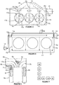
figure 4 représente une vue schématique d'une circulation d'un fluide caloporteur dans un deuxième circuit du système de refroidissement défini dans la culasse selon le mode de réalisation de l'invention ; - la
figure 5 représente une vue schématique d'une circulation d'un fluide caloporteur dans un premier circuit du système de refroidissement comprenant une chambre de distribution selon le mode de réalisation de l'invention ; - la
figure 6 représente une vue schématique en coupe transversale d'un moteur comprenant le système de refroidissement pourvu de la chambre de distribution selon le mode de réalisation de l'invention, et - la
figure 7 représente un logigramme relatif à un procédé de fabrication du moteur comprenant le système de refroidissement. - La
figure 3 est une représentation schématique d'un mode de réalisation d'un système de refroidissement 2 d'un moteur thermique 1 d'un véhicule automobile. Ce moteur 1 peut être un moteur à essence ou un moteur diesel notamment suralimenté ou encore un moteur 1 fonctionnant selon une technologie dite de « Flex fuel » et dont le système d'alimentation et carburation lui permet d'utiliser indifféremment des carburants aussi variés que l'essence, le bioéthanol ou un mélange des deux. Par exemple, dans le présent mode de réalisation, le système de refroidissement 2 est mis en oeuvre dans un moteur 1 présentant de forts niveaux de puissance spécifique. Ce système 2 peut comprendre un circuit principal 3 pourvu de composantes du moteur 1 telles qu'un bocal de dégazage 24, un module de suralimentation du moteur 1 comprenant un turbocompresseur 25, un échangeur de chaleur 26 tel qu'un aérotherme ou encore à un échangeur d'huile 27. - Sur les
figures 3 à 6 , un tel moteur 1 comprend un carter cylindres 5a pourvu d'une pluralité de cylindres 21 pouvant être rangés en ligne. Ce carter cylindres 5a est de préférence du type « à tablature ouverte » plus connu sous le terme anglo-saxon de « open deck ». Au-dessus du carter cylindres 5a, suivant un axe sensiblement parallèle à l'axe vertical des cylindres 21, vient se fixer la culasse 5b. Cette culasse 5b renferme notamment la distribution composée principalement des soupapes et des arbres à cames. Cette culasse 5b comprend également une face inférieure autrement appelée face de combustion ou face feu qui est destinée à être fixée sur une face supérieure du carter cylindres 5a, lequel étant disposé en-dessous de cette culasse 5b. Cette face de combustion délimite une chambre de combustion des cylindres 21 du moteur 1. La culasse comprend des conduits d'échappement 17a et des conduits d'admission 17b débouchant chacun dans la chambre de combustion et qui sont équipés respectivement de soupapes d'échappement et d'admission. Les conduits d'échappement 17a ou d'admission 17b sont séparés par une zone 19 relativement étroite dénommée « pontet ». Dans cette configuration, les pontets 19 se situent dans la partie de la culasse 5b soumise aux plus hautes températures, notamment pour les parties de ces pontets 19 localisées entre les conduits d'échappement 17a. De plus ces pontets 19 sont soumis à des cycles d'échauffement et de refroidissement à chaque cycle de fonctionnement du moteur 1. Ce sont des zones fragiles, davantage chauffées que les zones avoisinantes qui sont plus massives et ici dans ce mode de réalisation de l'invention mieux refroidies lors du fonctionnement du moteur 1. - On notera que la culasse 5b peut comprendre aussi un collecteur d'échappement 20 intégré pourvu d'une cavité, ou plénum, dans laquelle débouchent des premières extrémités des conduits d'échappement 17a dont des deuxièmes extrémités sont reliées aux chambres de combustion du moteur 1.
- Ce moteur 1 comprend également un joint de culasse 36 placé entre la culasse 5b et le carter cylindres 5a et en particulier entre les faces supérieure et inférieure précitées. Ce joint de culasse 36 participe à une liaison hermétique entre le carter cylindres 5a et la culasse 5b.
- Le circuit principal 3 de ce système 2 comprend un circuit interne 4 de refroidissement à l'intérieur du moteur 1 qui est pourvu : d'une pompe d'alimentation 14, des premier et deuxième circuits 6a, 6b de fluide et d'une chambre de distribution 7 pour alimenter le deuxième circuit 6b en fluide.
- La pompe d'alimentation 14 est destinée à mettre en circulation le fluide caloporteur encore appelé fluide de refroidissement dans ce circuit interne 4 de refroidissement du moteur 1. Les premier et deuxième circuits 6a, 6b sont respectivement compris dans le carter cylindres 5a et la culasse 5b. Ces premier et deuxième circuits 6a, 6b autrement appelés noyau ou chambre de fluide comprennent chacun un volume creux ou un évidement constitué de canaux de circulation qui est défini dans le carter cylindres 5a ou la culasse 5b du moteur 1 et dans lequel est destiné à circuler ce fluide de refroidissement, ici de l'eau ou de l'éthylène glycol avec ou sans adjuvants. On notera que le deuxième circuit 6b est également défini dans le collecteur d'échappement 20 intégré à la culasse 5b.
- Sur les
figures 3 à 6 , le premier circuit 6a comprend des première et deuxième parties 9a, 9b. La première partie 9a s'étend longitudinalement le long d'un côté d'une rangée de cylindres 21 du carter cylindres 5a. Cette première partie 9a comprend des compartiments supérieur et inférieur 7, 8 étanches et séparés par un élément de séparation 22 visible sur lafigure 6 . Le compartiment supérieur 7 est défini au niveau d'une partie supérieure du carter cylindres 5a et représente environ un-quart du volume de cette première partie 9a du premier circuit 6a. S'agissant du compartiment inférieur 8, il est défini entre un fond de cette première partie 9a du premier circuit 6a et l'élément de séparation 22. Il représente environ trois quart du volume de cette première partie 9a du premier circuit 6a. - L'élément de séparation 22 est de préférence une pièce rapportée dans la première partie 9a du premier circuit 6a du carter cylindres 5a après sa fabrication. Cet élément de séparation 22 s'étend longitudinalement de préférence sur toute la longueur de cette première partie 9a le long du côté de la rangée de cylindres 21 du carter cylindres 5a. Cet élément de séparation 22 peut être un insert ou une plaque qui est de préférence rigide et est réalisé en un matériau présentant des propriétés de résistance thermique élevée tel que le plastique ou encore un matériau composite.
- Le système 2 comprend un troisième circuit 6c comportant le compartiment inférieur 8 et la deuxième partie 9b du premier circuit 6a. Autrement dit, ce troisième circuit 6c correspond au premier circuit 6a dépourvu du compartiment supérieur 7. Tout comme le premier circuit 6a, ce troisième circuit 6c est défini dans le carter cylindres 5a et est destiné à assurer une circulation longitudinale du fluide caloporteur le long de côtés opposés d'une rangée de cylindres 21 du moteur 1 selon le sens des flèches en pointillées F1 illustrées sur la
figure 5 et/ou une circulation transversale du fluide caloporteur au travers du carter cylindres 5a notamment entre les cylindres 21 du moteur 1 selon le sens des flèches en pointillées F2 illustrées sur cettefigure 5 . Ce troisième circuit 6c comprend une entrée 10a correspondant à une entrée du compartiment inférieur 8 qui est reliée à la pompe d'alimentation 14 du système 2. Le troisième circuit 6c comprend une sortie 10b correspondant à une sortie de la deuxième partie 9b du premier circuit 6a qui est reliée à un élément de régulation 13 du débit de fluide dans ce troisième circuit 6c. - Cet élément de régulation 13 est défini pour autoriser/interdire une circulation du fluide caloporteur dans le troisième circuit 6c en fonction d'une température dudit fluide présent dans le troisième circuit 6c dudit carter cylindres 5a. Cet élément de régulation 13 peut être un thermostat pourvu d'un capteur de température plongé dans le fluide caloporteur présent dans ce troisième circuit 6c ou arrosé par ce fluide. Il peut s'agir d'un capteur de température compris dans le corps du thermostat ou encore un capteur déporté agencé dans ce troisième circuit 6c. Ce thermostat peut être par exemple un thermostat à cire comprenant deux clapets disposés aux deux extrémités d'un bulbe à cire et dont le fonctionnement est bien connu de l'état de la technique. Dans une variante, cet élément de régulation 13 peut être une vanne pilotée par exemple par une unité de traitement du système 2 qui est reliée à un capteur de température situé dans le troisième circuit 6c. L'élément de régulation 13 comprend une sortie qui est reliée à un boîtier 15 de sortie de fluide ou « Boîtier de Sortie d'Eau » plus connu sous l'acronyme BSE. Ce boîtier 15 qui est fixé au moteur 1, et de préférence à la culasse 5b du moteur 1, assure la collecte du fluide caloporteur ayant circulé dans le circuit interne 4 du moteur 1 et en particulier dans les deuxième et troisième circuits 6b, 6c ainsi que dans la chambre de distribution 7.
- Dans ce système 2, la chambre de distribution 7 est agencée dans le premier circuit 6a et est prévue pour alimenter le deuxième circuit 6b en fluide. Cette chambre de distribution 7 correspond au compartiment supérieur 7 du premier circuit 6a. La chambre 7 comprend une paroi inférieure formant le fond de cette chambre 7 correspondant à l'élément de séparation 22, et une ouverture ménagée dans la face supérieure du carter cylindres 5a et qui est recouverte par une partie du joint de culasse 36 lors de l'assemblage de ce carter cylindres 5a avec la culasse 5b et ce joint de culasse 36. Cette partie du joint de culasse 36 qui est agencée au niveau de ce compartiment supérieur 7 est pourvue d'orifices 18, sur la
figure 4 ce mode de réalisation en comprend trois. Ces orifices 18 visent à permettre une circulation du fluide caloporteur entre cette chambre de distribution 7 et le deuxième circuit 6b qui est défini dans la culasse 5b et ce, afin d'alimenter en fluide ce deuxième circuit 6b. Tout comme la première partie 9a du premier circuit 6a, la chambre de distribution 7 s'étend longitudinalement le long d'un côté d'une rangée de cylindres 21 du carter cylindres 5a et ce, au niveau d'une partie supérieure du carter cylindres 5a. La chambre de distribution 7 comprend une entrée 11 a reliée à la pompe d'alimentation 14 et une sortie 11 b reliée à une entrée 12a du deuxième circuit 6b. - Dans cette configuration, le fluide caloporteur compris dans la chambre de distribution 7 est mis en circulation par la pompe d'alimentation 14 de manière à traverser les orifices 18 du joint de culasse 36 et circuler dans le deuxième circuit 6b. Lorsque le fluide caloporteur émerge de ces orifices 18 dans le deuxième circuit 6b, ce dernier assure alors une circulation transversale du fluide au travers de la culasse 5b selon le sens des flèches F3 au niveau de la face de combustion notamment du pontet 19 défini sur cette face. Ainsi, le fluide de refroidissement est apte à circuler au niveau des pontets 19 de la face de combustion entre les conduits d'échappement 17a et d'admission 17b. Le deuxième circuit 6b est apte à assurer également une circulation longitudinale du fluide caloporteur selon le sens des flèches F4 le long d'au moins un côté de la face de combustion de la culasse 5b. Ce deuxième circuit 6b comprend une sortie 12b qui est reliée au boîtier 15 de sortie de fluide.
- Le système 2 comprend aussi un conduit d'entrée 16a de fluide du circuit interne 4 connecté notamment à une sortie d'un radiateur 23 mais également à des sorties de composantes du moteur 1 évoquées précédemment. Ce conduit d'entrée 16a comprend la pompe d'alimentation 14 pourvue d'une sortie reliée directement et de manière distincte à l'entrée 11a de la chambre de distribution 7 au niveau du compartiment supérieur 7 et à l'entrée 10a du troisième circuit 6c à savoir au niveau du compartiment inférieur 8. Ainsi la pompe d'alimentation 14 contribue à mettre en circulation le fluide caloporteur qu'elle reçoit notamment de ce radiateur et/ou des composantes du moteur 1, dans le troisième circuit 6c et le deuxième circuit 6b via la chambre de distribution 7. Le boîtier 15 de sortie de fluide est quant à lui relié à un conduit d'évacuation 16b de fluide du circuit interne 4. Ce conduit d'évacuation 16b est alors notamment connecté aux entrées du radiateur et des autres composantes du moteur 1 afin que le fluide caloporteur leurs soit transmis selon l'activation/désactivation d'une vanne 28 ou d'un thermostat 28 agencé dans le circuit principal 3 de refroidissement.
- Ce radiateur 23 qui est compris dans le circuit principal 3, constitue un échangeur thermique pour refroidir le fluide caloporteur en sortie du circuit interne 4 au niveau du conduit d'évacuation 16b. Le radiateur 23 est apte à renvoyer ensuite le fluide caloporteur refroidi vers le circuit interne 4 par l'intermédiaire du conduit d'entrée 16a pourvu de la pompe d'alimentation 14. Le système de refroidissement 2 du type à double refroidissement, souvent connu sous le terme anglo-saxon de « split-cooling » et dans lequel le fluide caloporteur circule de façon indépendante dans le troisième circuit 6c qui est défini dans le carter cylindres 5a et le deuxième circuit 6b compris dans la culasse 5b, la circulation dans le troisième circuit 6c n'étant établie qu'une fois une phase de préchauffage du carter cylindres 5a est achevée par l'activation de l'élément de régulation 13.
- Plus précisément, après le démarrage du moteur 1 du véhicule, le fluide caloporteur est mis en circulation dans le circuit interne 4 à partir de la pompe d'alimentation 14 dont la sortie est reliée aux entrées 10a, 11a des troisième et deuxième circuits 6c, 6b. Le débit du fluide caloporteur dans le troisième circuit 6c est contrôlé afin de mettre en oeuvre un processus de préchauffage du moteur et ainsi améliorer les performances de ce dernier tout en réduisant ainsi les émissions de polluants et la consommation de carburant. Ainsi, l'élément de régulation 13 interdit alors la circulation de ce fluide caloporteur dans le troisième circuit 6c lorsqu'une température du fluide présent dans ce circuit 6c est sensiblement inférieure à une température de référence. La température du fluide peut être estimée ou mesurée. Cette température de référence est définie en fonction des caractéristiques du moteur 1 et correspond de préférence à une température de fin de préchauffage du carter cylindres 5a. Par la suite, dès lors qu'une température du fluide présent dans ce troisième circuit 6c du carter cylindres 5a est sensiblement supérieure ou égale à la température de référence, l'élément de régulation 13 autorise la circulation du fluide dans ce troisième circuit 6c. Dans ces conditions, le fluide caloporteur mis en circulation par la pompe d'alimentation 13 circule à la fois dans les troisième et deuxième circuits 6c, 6b.
- En référence à la
figure 7 , l'invention concerne également un procédé de fabrication du moteur 1 notamment comprenant le carter cylindres 5a du type à tablature ouverte, comportant ce système de refroidissement 2. - Ce procédé comprend une étape d'obtention 29 du carter cylindres 5a et de la culasse 5b comprenant respectivement les premier et deuxième circuits 6a, 6b de fluide caloporteur. Cette étape d'obtention 29 met en oeuvre des processus de fabrication du carter cylindres 5a et de la culasse 5b, à partir notamment de procédés de moulage, de fonderie et/ou d'usinage bien connus de l'état de la technique. Le processus de fabrication par moulage peut par exemple prévoir l'utilisation de moules permanents (métallique) ou de moules destructibles (moule en sable ou en sel résorbable).
- Ce procédé comprend ensuite une étape de réalisation 30 de la chambre de distribution 7 dans le premier circuit 6a, ladite chambre 7 étant prévue pour alimenter le deuxième circuit 6b en fluide caloporteur. Cette étape 30 comprend une sous-étape d'agencement 31 d'un élément de séparation 22 dans la première partie 9a du premier circuit 6a s'étendant longitudinalement le long d'un côté d'une rangée de cylindres 21 du carter cylindres 5a.
- Par la suite le procédé comprend une étape d'assemblage 32 du carter cylindres 5a avec la culasse 5b. Cette étape 32 comprend une sous-étape de fixation 33 de la face inférieure de la culasse 5b avec la face supérieure de ce carter cylindres 5a, et une sous-étape d'insertion 34 du joint de culasse 36 entre ces faces inférieure et supérieure. Lors de cette sous-étape d'insertion 34, la partie du joint de culasse 36 qui est pourvue des orifices 18 est alors positionnée au niveau de l'ouverture du compartiment supérieur 7 comprise dans la face supérieure du carter cylindres 5a située dans la première partie 9a du premier circuit 6a.
- Le procédé comprend également une étape de montage 35 des composantes de fonctionnement du moteur 1 et du système de refroidissement 2 dans/sur le moteur 1. Ces composantes de fonctionnement du moteur 1 correspondent par exemple de manière non limitative et non exhaustive aux organes et éléments de distribution et/ou d'entraînement du moteur 1.
- Ainsi l'invention permet de réduire l'encombrement d'un moteur 1 notamment d'un moteur ayant une forte puissance spécifique, et qui est pourvu du système de refroidissement 2 notamment du type à double refroidissement. En particulier, l'invention permet d'assurer un refroidissement optimal et efficace au niveau des pontets 19 entre les conduits d'échappement 17a et d'admission 17b ce qui permet d'améliorer les échanges thermiques dans cette zone et de limiter les risques d'ébullition du fluide de refroidissement. Ainsi, le moteur 1 et en particulier la culasse 5b présentent une excellente tenue thermomécanique permettant d'éviter d'éventuels risques de fissure ou d'amorce de fissuration. Un tel moteur est alors plus compact plus léger et plus économique à réaliser.
Claims (10)
- Système de refroidissement (2) notamment du type à double refroidissement, d'un moteur thermique (1) d'un véhicule automobile comprenant des premier et deuxième circuits (6a, 6b) de fluide caloporteur définis respectivement dans un carter cylindres (5a) et une culasse (5b) dudit moteur (1), le système (2) comportant une chambre de distribution (7) agencée dans le premier circuit (6a) prévue pour alimenter le deuxième circuit (6b) en fluide.
- Système de refroidissement (2) selon la revendication précédente, caractérisé en ce que :- ladite chambre de distribution (7) correspond à un compartiment supérieur (7) d'une première partie (9a) du premier circuit (6a) comprenant des compartiments supérieur et inférieur (7, 8) séparés par un élément de séparation (22) ;- une première partie (9a) du premier circuit (6a) s'étend longitudinalement le long d'un côté d'une rangée de cylindres (21) du carter cylindres (5a), et- la chambre de distribution (7) comprend une entrée (11a) reliée à une pompe d'alimentation (14) et une sortie (11b) reliée à une entrée (12a) du deuxième circuit (6b).
- Système de refroidissement (2) selon l'une quelconque des revendications précédentes, caractérisé en ce qu'il comprend un troisième circuit (6c) assurant :- une circulation longitudinale du fluide caloporteur au travers du carter cylindres (5a) le long de côtés opposés d'une rangée de cylindres (21) du moteur (1), et- une circulation transversale du fluide caloporteur au travers du carter cylindres (5a) notamment entre les cylindres (21) du moteur (1).
- Système de refroidissement (2) selon l'une quelconque des revendications précédentes, caractérisé en ce que le deuxième circuit (6b) est défini dans la culasse (5b) et assure :- une circulation transversale du fluide caloporteur au travers de la culasse (5b) au niveau d'au moins une face de combustion notamment d'un pontet (19) défini sur cette face, et- une circulation longitudinale du fluide caloporteur le long d'au moins un côté d'une face de combustion de la culasse (5b).
- Système de refroidissement (2) selon l'une quelconque des revendications précédentes, caractérisé en ce que :- un troisième circuit (6c) comprend un compartiment inférieur (8) d'une première partie (9a) du premier circuit (6a) et une deuxième partie (9b) du premier circuit (6a) défini dans le carter cylindres (5a) ;- un troisième circuit (6c) comprend une entrée (10a) correspondant à une entrée du compartiment inférieur (8) qui est reliée à une pompe d'alimentation (14) du système (2), et- un troisième circuit (6c) comprend une sortie (10b) correspondant à une sortie d'une deuxième partie (9b) du premier circuit (6a) qui est reliée à un élément de régulation (13) du débit de fluide dans le troisième circuit (6c).
- Système de refroidissement (2) selon l'une quelconque des revendications précédentes, caractérisé en ce que :- un élément de séparation (22) est une pièce rapportée dans une première partie (9a) du premier circuit (6a), et- un élément de séparation (22) est réalisé en matériau plastique.
- Moteur thermique (1) notamment comprenant un carter cylindres (5a) du type à tablature ouverte, comportant un système de refroidissement (2) selon l'une quelconque des revendications précédentes.
- Procédé de fabrication d'un moteur thermique (1) notamment comprenant un carter cylindres (5a) du type à tablature ouverte, comportant un système de refroidissement (2) selon l'une quelconque des revendications 1 à 6, le procédé comprenant les étapes suivantes :- obtention (29) d'un carter cylindres (5a) et d'une culasse (5b) comprenant respectivement des premier et deuxième circuits (6a, 6b) de fluide caloporteur, et- réalisation (30) d'une chambre de distribution (7) dans le premier circuit (6a), ladite chambre (7) étant prévue pour alimenter le deuxième circuit (6b) en fluide.
- Procédé selon la revendication précédente, caractérisé en ce que l'étape de réalisation (30) d'une chambre de distribution (7) comprend une sous-étape d'agencement (31) d'un élément de séparation (22) dans une première partie (9a) du premier circuit (6a).
- Véhicule automobile comprenant un moteur thermique (1) selon la revendication 7.
Applications Claiming Priority (1)
| Application Number | Priority Date | Filing Date | Title |
|---|---|---|---|
| FR1655455A FR3052491B1 (fr) | 2016-06-13 | 2016-06-13 | Systeme de refroidissement d'un moteur thermique |
Publications (2)
| Publication Number | Publication Date |
|---|---|
| EP3258078A1 true EP3258078A1 (fr) | 2017-12-20 |
| EP3258078B1 EP3258078B1 (fr) | 2019-03-13 |
Family
ID=57485576
Family Applications (1)
| Application Number | Title | Priority Date | Filing Date |
|---|---|---|---|
| EP17175805.5A Active EP3258078B1 (fr) | 2016-06-13 | 2017-06-13 | Système de refroidissement d'un moteur thermique |
Country Status (2)
| Country | Link |
|---|---|
| EP (1) | EP3258078B1 (fr) |
| FR (1) | FR3052491B1 (fr) |
Citations (3)
| Publication number | Priority date | Publication date | Assignee | Title |
|---|---|---|---|---|
| US20060213460A1 (en) * | 2005-03-25 | 2006-09-28 | Mazda Motor Corporation | Cooling device of engine |
| JP2007291913A (ja) * | 2006-04-24 | 2007-11-08 | Mazda Motor Corp | エンジンの冷却装置 |
| WO2015086791A1 (fr) * | 2013-12-12 | 2015-06-18 | Avl List Gmbh | Moteur à combustion interne refroidi par liquide |
-
2016
- 2016-06-13 FR FR1655455A patent/FR3052491B1/fr not_active Expired - Fee Related
-
2017
- 2017-06-13 EP EP17175805.5A patent/EP3258078B1/fr active Active
Patent Citations (3)
| Publication number | Priority date | Publication date | Assignee | Title |
|---|---|---|---|---|
| US20060213460A1 (en) * | 2005-03-25 | 2006-09-28 | Mazda Motor Corporation | Cooling device of engine |
| JP2007291913A (ja) * | 2006-04-24 | 2007-11-08 | Mazda Motor Corp | エンジンの冷却装置 |
| WO2015086791A1 (fr) * | 2013-12-12 | 2015-06-18 | Avl List Gmbh | Moteur à combustion interne refroidi par liquide |
Also Published As
| Publication number | Publication date |
|---|---|
| FR3052491B1 (fr) | 2020-01-17 |
| FR3052491A1 (fr) | 2017-12-15 |
| EP3258078B1 (fr) | 2019-03-13 |
Similar Documents
| Publication | Publication Date | Title |
|---|---|---|
| CN110023607B (zh) | 内燃机的热管理系统和热管理方法 | |
| FR2486152A1 (fr) | Moteur a combustion interne a refroidissement par l'huile | |
| FR2955618A1 (fr) | Culasse de moteur a combustion interne comportant un circuit de refroidissement | |
| FR2924169A1 (fr) | Dispositif et procede de depollution et de chauffage pour vehicule automobile | |
| FR3036135A1 (fr) | Circuit de refroidissement d’un moteur | |
| EP2039906B1 (fr) | Procédé de régulation de la température d'un moteur thermique à turbocompresseur et refroidisseur d'air de suralimentation | |
| EP3258078B1 (fr) | Système de refroidissement d'un moteur thermique | |
| EP3555457B1 (fr) | Conduit de passage de liquide de refroidissement pour moteur à combustion interne de véhicule automobile | |
| EP2110536A1 (fr) | Architecture de collecteur d'échappement intégré à la culasse d'un moteur de véhicule automobile | |
| EP3183444A1 (fr) | Carter cylindre d'un moteur thermique | |
| FR3070432A1 (fr) | Ensemble d’un circuit de refroidissement pour un moteur thermique et une boite de vitesses | |
| EP1892389B1 (fr) | Dispositif permettant de commander un circuit de circulation d'un liquide de refroidissement ainsi qu'un circuit de circulation d'huile de lubrification d'un moteur thermique de véhicule | |
| EP1977096A2 (fr) | Dispositif permettant d'accelerer la montee en temperature d'huile de lubrification d'un moteur a combustion interne a turbocompresseur a gaz d'echappement | |
| EP3236041B1 (fr) | Système de refroidissement d'un moteur thermique | |
| FR2777606A1 (fr) | Dispositif de controle de la puissance de sortie d'un organe de chauffage a combustion pour moteur a combustion interne | |
| FR2890697A1 (fr) | Moteur de vehicule comprenant un circuit de gaz recircules refroidis a basse temperature | |
| FR2978206A1 (fr) | Dispositif de regulation thermique pour vehicule automobile | |
| EP0850791B1 (fr) | Système de chauffage de l'habitacle d'un véhicule automobile à moteur diesel à injection directe | |
| FR2908457A3 (fr) | Systeme de refroidissement d'un moteur thermique | |
| EP1892398A1 (fr) | Dispositif permettant de commander un circuit de circulation d'un liquide de refroidissement ainsi qu'un circuit de circulation d'huile de lubrification d'un moteur thermique de véhicule | |
| FR3064674A1 (fr) | Dispositif de gestion thermique d’un groupe motopropulseur de vehicule | |
| WO2023274739A1 (fr) | Piston pour moteur a combustion interne avec systeme de refroidissement optimise | |
| WO2023213852A1 (fr) | Turbomachine à échangeur thermique entre un circuit de carburant et deux circuits de lubrifiant | |
| EP2206896B1 (fr) | Dispositif de refroidissement de collecteur d'échappement intégré à la culasse d'un moteur de véhicule | |
| FR2936013A1 (fr) | Dispositif de regulation thermique pour un moteur. |
Legal Events
| Date | Code | Title | Description |
|---|---|---|---|
| PUAI | Public reference made under article 153(3) epc to a published international application that has entered the european phase |
Free format text: ORIGINAL CODE: 0009012 |
|
| STAA | Information on the status of an ep patent application or granted ep patent |
Free format text: STATUS: THE APPLICATION HAS BEEN PUBLISHED |
|
| AK | Designated contracting states |
Kind code of ref document: A1 Designated state(s): AL AT BE BG CH CY CZ DE DK EE ES FI FR GB GR HR HU IE IS IT LI LT LU LV MC MK MT NL NO PL PT RO RS SE SI SK SM TR |
|
| AX | Request for extension of the european patent |
Extension state: BA ME |
|
| STAA | Information on the status of an ep patent application or granted ep patent |
Free format text: STATUS: REQUEST FOR EXAMINATION WAS MADE |
|
| 17P | Request for examination filed |
Effective date: 20180618 |
|
| RBV | Designated contracting states (corrected) |
Designated state(s): AL AT BE BG CH CY CZ DE DK EE ES FI FR GB GR HR HU IE IS IT LI LT LU LV MC MK MT NL NO PL PT RO RS SE SI SK SM TR |
|
| RIC1 | Information provided on ipc code assigned before grant |
Ipc: F01P 3/02 20060101AFI20180813BHEP |
|
| GRAP | Despatch of communication of intention to grant a patent |
Free format text: ORIGINAL CODE: EPIDOSNIGR1 |
|
| STAA | Information on the status of an ep patent application or granted ep patent |
Free format text: STATUS: GRANT OF PATENT IS INTENDED |
|
| INTG | Intention to grant announced |
Effective date: 20181008 |
|
| GRAS | Grant fee paid |
Free format text: ORIGINAL CODE: EPIDOSNIGR3 |
|
| GRAA | (expected) grant |
Free format text: ORIGINAL CODE: 0009210 |
|
| STAA | Information on the status of an ep patent application or granted ep patent |
Free format text: STATUS: THE PATENT HAS BEEN GRANTED |
|
| AK | Designated contracting states |
Kind code of ref document: B1 Designated state(s): AL AT BE BG CH CY CZ DE DK EE ES FI FR GB GR HR HU IE IS IT LI LT LU LV MC MK MT NL NO PL PT RO RS SE SI SK SM TR |
|
| REG | Reference to a national code |
Ref country code: GB Ref legal event code: FG4D Free format text: NOT ENGLISH |
|
| REG | Reference to a national code |
Ref country code: CH Ref legal event code: EP Ref country code: AT Ref legal event code: REF Ref document number: 1107985 Country of ref document: AT Kind code of ref document: T Effective date: 20190315 |
|
| REG | Reference to a national code |
Ref country code: IE Ref legal event code: FG4D Free format text: LANGUAGE OF EP DOCUMENT: FRENCH |
|
| REG | Reference to a national code |
Ref country code: DE Ref legal event code: R096 Ref document number: 602017002650 Country of ref document: DE |
|
| REG | Reference to a national code |
Ref country code: NL Ref legal event code: MP Effective date: 20190313 |
|
| REG | Reference to a national code |
Ref country code: LT Ref legal event code: MG4D |
|
| PG25 | Lapsed in a contracting state [announced via postgrant information from national office to epo] |
Ref country code: LT Free format text: LAPSE BECAUSE OF FAILURE TO SUBMIT A TRANSLATION OF THE DESCRIPTION OR TO PAY THE FEE WITHIN THE PRESCRIBED TIME-LIMIT Effective date: 20190313 Ref country code: NO Free format text: LAPSE BECAUSE OF FAILURE TO SUBMIT A TRANSLATION OF THE DESCRIPTION OR TO PAY THE FEE WITHIN THE PRESCRIBED TIME-LIMIT Effective date: 20190613 Ref country code: SE Free format text: LAPSE BECAUSE OF FAILURE TO SUBMIT A TRANSLATION OF THE DESCRIPTION OR TO PAY THE FEE WITHIN THE PRESCRIBED TIME-LIMIT Effective date: 20190313 Ref country code: FI Free format text: LAPSE BECAUSE OF FAILURE TO SUBMIT A TRANSLATION OF THE DESCRIPTION OR TO PAY THE FEE WITHIN THE PRESCRIBED TIME-LIMIT Effective date: 20190313 |
|
| PG25 | Lapsed in a contracting state [announced via postgrant information from national office to epo] |
Ref country code: BG Free format text: LAPSE BECAUSE OF FAILURE TO SUBMIT A TRANSLATION OF THE DESCRIPTION OR TO PAY THE FEE WITHIN THE PRESCRIBED TIME-LIMIT Effective date: 20190613 Ref country code: GR Free format text: LAPSE BECAUSE OF FAILURE TO SUBMIT A TRANSLATION OF THE DESCRIPTION OR TO PAY THE FEE WITHIN THE PRESCRIBED TIME-LIMIT Effective date: 20190614 Ref country code: RS Free format text: LAPSE BECAUSE OF FAILURE TO SUBMIT A TRANSLATION OF THE DESCRIPTION OR TO PAY THE FEE WITHIN THE PRESCRIBED TIME-LIMIT Effective date: 20190313 Ref country code: LV Free format text: LAPSE BECAUSE OF FAILURE TO SUBMIT A TRANSLATION OF THE DESCRIPTION OR TO PAY THE FEE WITHIN THE PRESCRIBED TIME-LIMIT Effective date: 20190313 Ref country code: HR Free format text: LAPSE BECAUSE OF FAILURE TO SUBMIT A TRANSLATION OF THE DESCRIPTION OR TO PAY THE FEE WITHIN THE PRESCRIBED TIME-LIMIT Effective date: 20190313 Ref country code: NL Free format text: LAPSE BECAUSE OF FAILURE TO SUBMIT A TRANSLATION OF THE DESCRIPTION OR TO PAY THE FEE WITHIN THE PRESCRIBED TIME-LIMIT Effective date: 20190313 |
|
| REG | Reference to a national code |
Ref country code: AT Ref legal event code: MK05 Ref document number: 1107985 Country of ref document: AT Kind code of ref document: T Effective date: 20190313 |
|
| PG25 | Lapsed in a contracting state [announced via postgrant information from national office to epo] |
Ref country code: IT Free format text: LAPSE BECAUSE OF FAILURE TO SUBMIT A TRANSLATION OF THE DESCRIPTION OR TO PAY THE FEE WITHIN THE PRESCRIBED TIME-LIMIT Effective date: 20190313 Ref country code: RO Free format text: LAPSE BECAUSE OF FAILURE TO SUBMIT A TRANSLATION OF THE DESCRIPTION OR TO PAY THE FEE WITHIN THE PRESCRIBED TIME-LIMIT Effective date: 20190313 Ref country code: SK Free format text: LAPSE BECAUSE OF FAILURE TO SUBMIT A TRANSLATION OF THE DESCRIPTION OR TO PAY THE FEE WITHIN THE PRESCRIBED TIME-LIMIT Effective date: 20190313 Ref country code: CZ Free format text: LAPSE BECAUSE OF FAILURE TO SUBMIT A TRANSLATION OF THE DESCRIPTION OR TO PAY THE FEE WITHIN THE PRESCRIBED TIME-LIMIT Effective date: 20190313 Ref country code: AL Free format text: LAPSE BECAUSE OF FAILURE TO SUBMIT A TRANSLATION OF THE DESCRIPTION OR TO PAY THE FEE WITHIN THE PRESCRIBED TIME-LIMIT Effective date: 20190313 Ref country code: PT Free format text: LAPSE BECAUSE OF FAILURE TO SUBMIT A TRANSLATION OF THE DESCRIPTION OR TO PAY THE FEE WITHIN THE PRESCRIBED TIME-LIMIT Effective date: 20190713 Ref country code: ES Free format text: LAPSE BECAUSE OF FAILURE TO SUBMIT A TRANSLATION OF THE DESCRIPTION OR TO PAY THE FEE WITHIN THE PRESCRIBED TIME-LIMIT Effective date: 20190313 Ref country code: EE Free format text: LAPSE BECAUSE OF FAILURE TO SUBMIT A TRANSLATION OF THE DESCRIPTION OR TO PAY THE FEE WITHIN THE PRESCRIBED TIME-LIMIT Effective date: 20190313 |
|
| PG25 | Lapsed in a contracting state [announced via postgrant information from national office to epo] |
Ref country code: SM Free format text: LAPSE BECAUSE OF FAILURE TO SUBMIT A TRANSLATION OF THE DESCRIPTION OR TO PAY THE FEE WITHIN THE PRESCRIBED TIME-LIMIT Effective date: 20190313 Ref country code: PL Free format text: LAPSE BECAUSE OF FAILURE TO SUBMIT A TRANSLATION OF THE DESCRIPTION OR TO PAY THE FEE WITHIN THE PRESCRIBED TIME-LIMIT Effective date: 20190313 |
|
| REG | Reference to a national code |
Ref country code: DE Ref legal event code: R097 Ref document number: 602017002650 Country of ref document: DE |
|
| PG25 | Lapsed in a contracting state [announced via postgrant information from national office to epo] |
Ref country code: IS Free format text: LAPSE BECAUSE OF FAILURE TO SUBMIT A TRANSLATION OF THE DESCRIPTION OR TO PAY THE FEE WITHIN THE PRESCRIBED TIME-LIMIT Effective date: 20190713 Ref country code: AT Free format text: LAPSE BECAUSE OF FAILURE TO SUBMIT A TRANSLATION OF THE DESCRIPTION OR TO PAY THE FEE WITHIN THE PRESCRIBED TIME-LIMIT Effective date: 20190313 |
|
| PLBE | No opposition filed within time limit |
Free format text: ORIGINAL CODE: 0009261 |
|
| STAA | Information on the status of an ep patent application or granted ep patent |
Free format text: STATUS: NO OPPOSITION FILED WITHIN TIME LIMIT |
|
| PG25 | Lapsed in a contracting state [announced via postgrant information from national office to epo] |
Ref country code: MC Free format text: LAPSE BECAUSE OF FAILURE TO SUBMIT A TRANSLATION OF THE DESCRIPTION OR TO PAY THE FEE WITHIN THE PRESCRIBED TIME-LIMIT Effective date: 20190313 Ref country code: DK Free format text: LAPSE BECAUSE OF FAILURE TO SUBMIT A TRANSLATION OF THE DESCRIPTION OR TO PAY THE FEE WITHIN THE PRESCRIBED TIME-LIMIT Effective date: 20190313 |
|
| 26N | No opposition filed |
Effective date: 20191216 |
|
| PG25 | Lapsed in a contracting state [announced via postgrant information from national office to epo] |
Ref country code: SI Free format text: LAPSE BECAUSE OF FAILURE TO SUBMIT A TRANSLATION OF THE DESCRIPTION OR TO PAY THE FEE WITHIN THE PRESCRIBED TIME-LIMIT Effective date: 20190313 |
|
| REG | Reference to a national code |
Ref country code: BE Ref legal event code: MM Effective date: 20190630 |
|
| PG25 | Lapsed in a contracting state [announced via postgrant information from national office to epo] |
Ref country code: TR Free format text: LAPSE BECAUSE OF FAILURE TO SUBMIT A TRANSLATION OF THE DESCRIPTION OR TO PAY THE FEE WITHIN THE PRESCRIBED TIME-LIMIT Effective date: 20190313 |
|
| PG25 | Lapsed in a contracting state [announced via postgrant information from national office to epo] |
Ref country code: IE Free format text: LAPSE BECAUSE OF NON-PAYMENT OF DUE FEES Effective date: 20190613 |
|
| PG25 | Lapsed in a contracting state [announced via postgrant information from national office to epo] |
Ref country code: LU Free format text: LAPSE BECAUSE OF NON-PAYMENT OF DUE FEES Effective date: 20190613 Ref country code: BE Free format text: LAPSE BECAUSE OF NON-PAYMENT OF DUE FEES Effective date: 20190630 |
|
| REG | Reference to a national code |
Ref country code: CH Ref legal event code: PL |
|
| PG25 | Lapsed in a contracting state [announced via postgrant information from national office to epo] |
Ref country code: CH Free format text: LAPSE BECAUSE OF NON-PAYMENT OF DUE FEES Effective date: 20200630 Ref country code: LI Free format text: LAPSE BECAUSE OF NON-PAYMENT OF DUE FEES Effective date: 20200630 |
|
| PG25 | Lapsed in a contracting state [announced via postgrant information from national office to epo] |
Ref country code: CY Free format text: LAPSE BECAUSE OF FAILURE TO SUBMIT A TRANSLATION OF THE DESCRIPTION OR TO PAY THE FEE WITHIN THE PRESCRIBED TIME-LIMIT Effective date: 20190313 |
|
| PG25 | Lapsed in a contracting state [announced via postgrant information from national office to epo] |
Ref country code: MT Free format text: LAPSE BECAUSE OF FAILURE TO SUBMIT A TRANSLATION OF THE DESCRIPTION OR TO PAY THE FEE WITHIN THE PRESCRIBED TIME-LIMIT Effective date: 20190313 Ref country code: HU Free format text: LAPSE BECAUSE OF FAILURE TO SUBMIT A TRANSLATION OF THE DESCRIPTION OR TO PAY THE FEE WITHIN THE PRESCRIBED TIME-LIMIT; INVALID AB INITIO Effective date: 20170613 |
|
| GBPC | Gb: european patent ceased through non-payment of renewal fee |
Effective date: 20210613 |
|
| PG25 | Lapsed in a contracting state [announced via postgrant information from national office to epo] |
Ref country code: GB Free format text: LAPSE BECAUSE OF NON-PAYMENT OF DUE FEES Effective date: 20210613 |
|
| PG25 | Lapsed in a contracting state [announced via postgrant information from national office to epo] |
Ref country code: MK Free format text: LAPSE BECAUSE OF FAILURE TO SUBMIT A TRANSLATION OF THE DESCRIPTION OR TO PAY THE FEE WITHIN THE PRESCRIBED TIME-LIMIT Effective date: 20190313 |
|
| P01 | Opt-out of the competence of the unified patent court (upc) registered |
Effective date: 20230608 |
|
| REG | Reference to a national code |
Ref country code: DE Ref legal event code: R081 Ref document number: 602017002650 Country of ref document: DE Owner name: NEW H POWERTRAIN HOLDING, S.L.U., ES Free format text: FORMER OWNER: RENAULT S.A.S., BOULOGNE BILLANCOURT, FR |
|
| PGFP | Annual fee paid to national office [announced via postgrant information from national office to epo] |
Ref country code: DE Payment date: 20250618 Year of fee payment: 9 |
|
| PGFP | Annual fee paid to national office [announced via postgrant information from national office to epo] |
Ref country code: FR Payment date: 20250625 Year of fee payment: 9 |