EP3258001A1 - Drainage structure for washing machine - Google Patents
Drainage structure for washing machine Download PDFInfo
- Publication number
- EP3258001A1 EP3258001A1 EP15881835.1A EP15881835A EP3258001A1 EP 3258001 A1 EP3258001 A1 EP 3258001A1 EP 15881835 A EP15881835 A EP 15881835A EP 3258001 A1 EP3258001 A1 EP 3258001A1
- Authority
- EP
- European Patent Office
- Prior art keywords
- stop lever
- lever assembly
- valve rod
- washing machine
- valve
- Prior art date
- Legal status (The legal status is an assumption and is not a legal conclusion. Google has not performed a legal analysis and makes no representation as to the accuracy of the status listed.)
- Granted
Links
Images



Classifications
-
- D—TEXTILES; PAPER
- D06—TREATMENT OF TEXTILES OR THE LIKE; LAUNDERING; FLEXIBLE MATERIALS NOT OTHERWISE PROVIDED FOR
- D06F—LAUNDERING, DRYING, IRONING, PRESSING OR FOLDING TEXTILE ARTICLES
- D06F39/00—Details of washing machines not specific to a single type of machines covered by groups D06F9/00 - D06F27/00
- D06F39/08—Liquid supply or discharge arrangements
- D06F39/083—Liquid discharge or recirculation arrangements
-
- D—TEXTILES; PAPER
- D06—TREATMENT OF TEXTILES OR THE LIKE; LAUNDERING; FLEXIBLE MATERIALS NOT OTHERWISE PROVIDED FOR
- D06F—LAUNDERING, DRYING, IRONING, PRESSING OR FOLDING TEXTILE ARTICLES
- D06F37/00—Details specific to washing machines covered by groups D06F21/00 - D06F25/00
- D06F37/26—Casings; Tubs
- D06F37/267—Tubs specially adapted for mounting thereto components or devices not provided for in preceding subgroups
-
- F—MECHANICAL ENGINEERING; LIGHTING; HEATING; WEAPONS; BLASTING
- F16—ENGINEERING ELEMENTS AND UNITS; GENERAL MEASURES FOR PRODUCING AND MAINTAINING EFFECTIVE FUNCTIONING OF MACHINES OR INSTALLATIONS; THERMAL INSULATION IN GENERAL
- F16K—VALVES; TAPS; COCKS; ACTUATING-FLOATS; DEVICES FOR VENTING OR AERATING
- F16K15/00—Check valves
- F16K15/02—Check valves with guided rigid valve members
- F16K15/04—Check valves with guided rigid valve members shaped as balls
-
- F—MECHANICAL ENGINEERING; LIGHTING; HEATING; WEAPONS; BLASTING
- F16—ENGINEERING ELEMENTS AND UNITS; GENERAL MEASURES FOR PRODUCING AND MAINTAINING EFFECTIVE FUNCTIONING OF MACHINES OR INSTALLATIONS; THERMAL INSULATION IN GENERAL
- F16K—VALVES; TAPS; COCKS; ACTUATING-FLOATS; DEVICES FOR VENTING OR AERATING
- F16K31/00—Actuating devices; Operating means; Releasing devices
- F16K31/44—Mechanical actuating means
-
- D—TEXTILES; PAPER
- D06—TREATMENT OF TEXTILES OR THE LIKE; LAUNDERING; FLEXIBLE MATERIALS NOT OTHERWISE PROVIDED FOR
- D06F—LAUNDERING, DRYING, IRONING, PRESSING OR FOLDING TEXTILE ARTICLES
- D06F2105/00—Systems or parameters controlled or affected by the control systems of washing machines, washer-dryers or laundry dryers
- D06F2105/08—Draining of washing liquids
-
- D—TEXTILES; PAPER
- D06—TREATMENT OF TEXTILES OR THE LIKE; LAUNDERING; FLEXIBLE MATERIALS NOT OTHERWISE PROVIDED FOR
- D06F—LAUNDERING, DRYING, IRONING, PRESSING OR FOLDING TEXTILE ARTICLES
- D06F23/00—Washing machines with receptacles, e.g. perforated, having a rotary movement, e.g. oscillatory movement, the receptacle serving both for washing and for centrifugally separating water from the laundry
- D06F23/04—Washing machines with receptacles, e.g. perforated, having a rotary movement, e.g. oscillatory movement, the receptacle serving both for washing and for centrifugally separating water from the laundry and rotating or oscillating about a vertical axis
-
- D—TEXTILES; PAPER
- D06—TREATMENT OF TEXTILES OR THE LIKE; LAUNDERING; FLEXIBLE MATERIALS NOT OTHERWISE PROVIDED FOR
- D06F—LAUNDERING, DRYING, IRONING, PRESSING OR FOLDING TEXTILE ARTICLES
- D06F37/00—Details specific to washing machines covered by groups D06F21/00 - D06F25/00
- D06F37/02—Rotary receptacles, e.g. drums
- D06F37/12—Rotary receptacles, e.g. drums adapted for rotation or oscillation about a vertical axis
-
- D—TEXTILES; PAPER
- D06—TREATMENT OF TEXTILES OR THE LIKE; LAUNDERING; FLEXIBLE MATERIALS NOT OTHERWISE PROVIDED FOR
- D06F—LAUNDERING, DRYING, IRONING, PRESSING OR FOLDING TEXTILE ARTICLES
- D06F39/00—Details of washing machines not specific to a single type of machines covered by groups D06F9/00 - D06F27/00
- D06F39/08—Liquid supply or discharge arrangements
- D06F39/083—Liquid discharge or recirculation arrangements
- D06F39/086—Arrangements for avoiding detergent wastage in the discharge conduit
Definitions
- the present invention relates to the technical field of washing machines, and particularly relates to a washing machine drainage structure.
- a washing machine with a simple clothes washing function cannot meet the demands of people.
- energy and development have become a theme of social development, so people do not only have a basic clothes washing demand on the washing machine, but also take energy saving as an important factor to measure the washing machine.
- An ordinary pulsator washing machine has a large amount of water between an inner tub and an outer tub in a water supplying process, so that the water outside the inner tub is wasted in a washing process.
- the above water-saving type washing machine also has a defect that as the inner tub is not provided with dehydration and drainage holes, water cannot be drained in time in a dehydrating process, and the dehydrating process starts slowly with great vibrations and takes a relatively long time for dehydration, so that the energy efficiency is low and the dehydrated clothes have a relatively high water content.
- the present invention provides a washing machine drainage structure. Specifically, a technical solution adopted by the present invention is as follows.
- a washing machine drainage structure for a washing machine which has no water between an inner tub and an outer tub in washing and rinsing processes, the washing machine comprises an inner tub without holes in the lower part of a tub side wall, a drainage outlet is arranged at a bottom wall of the inner tub, a water inlet end of a ball valve is communicated with the drainage outlet, and the ball valve is driven by the driving device to be closed in the washing and rinsing processes and opened in a draining procedure.
- the ball valve comprises a first valve rod and a second valve rod
- the driving device drives the first valve rod to rotate for 90 degrees to open the ball valve
- the driving device drives the second valve rod to reversely rotate for 90 degrees to close the ball valve
- the ball valve comprises a valve casing and a ball body, the ball body is rotatably arranged in the valve casing, and the first valve rod and the second valve rod are connected respectively with the ball body of the ball valve through a hinge.
- the washing machine comprises an outer tub coaxially mounted outside the inner tub;
- the driving device comprises a first stop lever assembly and a second stop lever assembly, both of which are mounted on a bottom wall of the outer tub; and the first valve rod is stopped by the first stop lever assembly and rotates for 90 degrees in a reverse direction so as to open the ball valve when the inner tub rotates in a forward direction, and the second valve rod is stopped by the second stop lever assembly and rotates for 90 degrees in the forward direction so as to close the ball valve when the inner tub rotates in the reverse direction.
- first valve rod rotates for 90 degrees in the reverse direction as being stopped by the first stop lever assembly and then is separated from the first stop lever assembly
- second valve rod rotates for 90 degrees in the forward direction as being stopped by the second stop lever assembly and then is separated from the second stop lever assembly.
- each of the first stop lever assembly and the second stop lever assembly respectively comprises a stop lever capable of moving upwards and downwards;
- the first stop lever assembly is arranged at the outer side of the second stop lever assembly, and the length of the first valve rod is larger than the length of the second valve rod, so that the stop lever of the first stop lever assembly only stops the first valve rod when moving upwards;
- the length of the stop lever of the second stop lever assembly is smaller than the length of the stop lever of the first stop lever assembly, and a distance between the second valve rod and the bottom wall of the outer tub is smaller than a distance between the first valve rod and the bottom wall of the outer tub, so that the stop lever of the second stop lever assembly only stops the second valve rod when moving upwards.
- each of the first stop lever assembly and the second stop lever assembly comprises the stop lever, a nut, a sealing sleeve, a fixing disk and a compression spring
- the stop levers pass through the bottom wall of the outer tub
- the upper part of each stop lever is located between the inner tub and the outer tub
- the lower part of each stop lever is located at the exterior of the bottom wall of the outer tub
- each sealing sleeve is set on the upper part of the stop lever and extends and contracts along with the movement of the stop lever, one end of each sealing sleeve is fixed on the stop lever through the nut, and the other end of each sealing sleeve is fixed on the bottom wall of the outer tub through the fixing disk in a sealed manner
- each spring is set over the lower part of the stop lever.
- each compression spring is arranged at the lower end of the stop lever, and each compression spring is arranged between the bottom wall of the outer tub and the stop nut.
- the bottom wall of the outer tub is provided with a groove structure
- the first stop lever assembly and the second stop lever assembly are mounted in the groove structure
- the groove structure is provided with an outer tub drainage outlet.
- the driving device further comprises a press plate, a support, a pull rod and a traction motor
- the support is fixed on the outer side of the bottom wall of the outer tub
- the pull rod is rotatably mounted on the support
- one end of the pull rod is connected with the traction motor
- the other end of the pull rod is fixedly connected with the press plate
- the pull rod and the press plate rotate around the support under the traction of the traction motor, when one end of the press plate moves upwards, the press plate presses the first stop lever assembly to move upwards, and the other end of the press plate moves downwards and then the second stop lever assembly moves downwards.
- the dehydration and drainage holes are arranged at positions above the maximum water level of the inner tub of the washing machine and are used for draining dehydrated water in a dehydrating process, and other parts of the side wall of the inner tub are designed to be closed and are not provided with any through hole structure.
- the drainage outlet with a relatively large aperture is arranged at the bottom wall of the inner tub, the drainage outlet is closed in the washing and rinsing processes and is opened in the draining process, and other parts of the bottom wall of the inner tub are designed to be closed.
- the drainage structure provided by the present invention is applicable to the washing machine with the inner tub, the bottom wall of the inner tub is provided with the drainage outlet, and the ball valve of the drainage structure is driven by the driving device to be closed in the washing and rinsing processes and opened in the draining process. Therefore, according to the drainage structure provided by the present invention, the ball valve is driven by the driving device to be closed or opened so as to close or open the drainage outlet , thereby implementing drainage of the washing machine without holes in the lower part of the side wall of the inner tub; and the drainage structure provided by the present invention has a simple structure, is convenient to be mounted and is very valuable for market popularization.
- a washing machine drainage structure for a washing machine in which there is not water between an inner tub and an outer tub in washing and rinsing processes, is provided.
- the washing machine comprises an inner tub 1 without holes in the lower part of a tub side wall.
- the drainage structure comprises a ball valve 33 and a driving device.
- a drainage outlet is arranged at a bottom wall of the inner tub 1, a water inlet end of the ball valve 33 is communicated with the drainage outlet.
- the ball valve 33 is driven by the driving device to be closed in the washing and rinsing processes and opened in a draining procedure.
- only the upper part of a side wall of the inner tub 1 is provided with dehydration and drainage holes in a circle.
- the dehydration and drainage holes are arranged at positions above the maximum water level of the inner tub of the washing machine and are used for draining dehydrated water in a dehydrating process, and other parts of the side wall of the inner tub 1 are designed to be closed and are not provided with any through hole structure.
- the drainage outlet with a larger aperture is arranged at the bottom wall of the inner tub 1. The drainage outlet is closed in the washing and rinsing processes and is opened in the draining process, and other parts of the bottom wall of the inner tub 1 are designed to be closed.
- the ball valve is a valve in which a ball body with a circular channel serves as an open-close component and which is opened and closed as the ball body rotates along with valve rods.
- the open-close component of the ball valve is a ball body with a hole and rotates around an axial line vertical to the channel so as to achieve the purpose of opening and closing the channel.
- the ball valve is mainly used for opening and closing a pipeline and a device medium. Therefore, in the washing machine drainage structure provided by the present invention, the ball valve 33 is mounted on the drainage outlet and is opened and closed by the driving device driving the valve rods of the ball valve 33 according to the working principles of the ball valve.
- the drainage structure provided by the present invention is applicable to the washing machine in which there is not water between an inner tub and an outer tub in washing and rinsing processes.
- the drainage outlet is arranged at the bottom wall of the inner tub 1, and the ball valve 33 of the drainage structure is driven by the driving device to be closed in the washing and rinsing processes and opened in the draining process. Therefore, according to the drainage structure provided by the present invention, the ball valve is driven by the driving device to be closed or opened so as to close or open the drainage outlet , thereby implementing drainage.
- the washing machine drainage structure provided by the present invention has a simple structure, is convenient to be mounted and is very valuable for market popularization.
- the ball valve 33 comprises a first valve rod 30 and a second valve rod 31.
- the driving device drives the first valve rod 30 to rotate for 90 degrees to open the ball valve 33, and the driving device drives the second valve rod 31 to reversely rotate for 90 degrees to close the ball valve 33.
- the ball valve 33 comprises two valve rods for controlling the opening and closing of the ball valve 33 respectively, so that the ball valve 33 can be opened and closed by just controlling the driving device to control the first valve rod 30 and the second valve rod 31 to rotate.
- the ball valve 33 comprises a valve casing and a ball body, the ball body is rotatably arranged in the valve casing, and the first valve rod 30 and the second valve rod 31 are connected respectively with the ball body of the ball valve 33 through a hinge 32.
- the present invention adopts the following technical solution to drive the first valve rod 30 and the second valve rod 31 to rotate.
- the washing machine comprises an outer tub 13 coaxially mounted outside the inner tub1.
- the driving device comprises a first stop lever assembly 16 and a second stop lever assembly 17, both of which are mounted on the bottom wall of the outer tub 13.
- the first valve rod 30 is stopped by the first stop lever assembly 16 and rotates for 90 degrees in a reverse direction so as to open the ball valve 33 when the inner tub 1 rotates in a forward direction
- the second valve rod 31 is stopped by the second stop lever assembly 17 and rotates for 90 degrees in the forward direction so as to close the ball valve 33 when the inner tub 1 rotates in the reverse direction.
- the rotation in the forward direction or the reverse direction does not limit rotation of the inner tub 1 in a constant direction, but only limits rotation of the inner tub 1 in two directions in the draining process.
- a clockwise direction is the forward direction
- an anticlockwise direction is the reverse direction, vice versa.
- the inner tub 1 rotates in the clockwise direction as the forward direction
- the inner tub 1 rotates in the anticlockwise direction as the reverse direction.
- the inner tub 1 rotates in two directions in order to open the ball valve 33 before draining and to close the ball valve 33 after the draining is completed.
- each of the first stop lever assembly 16 and the second stop lever assembly 17 comprises a stop lever 23 capable of moving upwards and downwards.
- the stop levers 23 of the first stop lever assembly 16 and the second stop lever assembly 17 need to respectively act on the first valve rod 30 and the second valve rod 31.
- the ball valve 33 cannot be opened and closed if action objects are wrong.
- the first stop lever assembly 16 is arranged outside the second stop lever assembly 17.
- the length of the first valve rod 30 is larger than the length of the second valve rod 31, so that the stop lever 23 of the first stop lever assembly 16 only stops the first valve rod 30 when moving upwards.
- the first stop lever assembly 16 is arranged on the outer side of a free end of the second valve rod 31.
- the first stop lever assembly 16 cannot stop the second valve rod 31 and only can stop the first valve rod 30 when moving upwards.
- the first valve rod 30 drives the channel of the ball body of the ball valve 33 to be opened as being stopped by the first stop lever assembly 16, and the ball valve 33 is opened.
- the length of the stop lever 23 of the second stop lever assembly 17 is smaller than the length of the stop lever 23 of the first stop lever assembly 16.
- a distance between the second valve rod 31 and the bottom wall of the outer tub 13 is smaller than a distance between the first valve rod 30 and the bottom wall of the outer tub 13, so that the stop lever 23 of the second stop lever assembly 17 only stops the second valve rod 31 when moving upwards.
- the height of the stop lever 23 of the second stop lever assembly 17 moving upwards only can allow that the stop rod 23 of the second stop rod assembly 17 to stop the second valve rod 31 rather than the first valve rod 30.
- the second valve rod 31 drives the channel of the ball body of the ball valve 33 to be closed as being stopped by the stop lever 23 of the second stop lever assembly 17, and the ball valve 33 is closed.
- the lengths of the first valve rod 30 and the second valve rod 31 meet: the first valve rod 30 rotates for 90 degrees in the reverse direction as being stopped by the first stop lever assembly 16 and then is separated from the first stop lever assembly 16, and the second valve rod 31 rotates for 90 degrees in the forward direction as being stopped by the second stop lever assembly 17 and then is separated from the second stop lever assembly 17.
- the ball valve 33 can be opened and closed only after the first valve rod 30 and the second valve rod 31 rotate to right positions. Besides, when the ball valve 33 is opened and closed, the first valve rod 30 and the second valve rod 31 cannot rotate anymore after rotating to the right positions, and the first stop lever assembly 16 and the second stop lever assembly 17 must be separated from the first valve rod 30 and the second valve rod 31 so as to not influence operation of the inner tub1.
- each of the first stop lever assembly 16 and the second stop lever assembly 17 comprises the stop lever 23, a nut 24, a sealing sleeve 25, a fixing disk 26 and a compression spring 27.
- the stop levers 23 pass through the bottom wall of the outer tub 13.
- the stop levers 23 of the first stop lever assembly 16 and the second stop lever assembly 17 can move upwards and downwards in order to stop the first valve rod 30 and the second valve rod 31.
- the upper part of each stop lever 23 is located between the inner tub 1 and the outer tub 13, and the lower part of each stop lever 23 is located at the exterior of the bottom wall of the outer tub 13.
- the sealing sleeve 25 is set on the upper part of the corresponding stop lever 23 and can extend and contract along with the movement of the corresponding stop lever 23.
- One end of each sealing sleeve 25 is fixed on the corresponding stop lever 23 through the nut 24, and the other end of each sealing sleeve 25 is fixed on the bottom wall of the outer tub 13 through the fixing disk in a sealed manner in order to keep sealing between the first stop lever assembly 16 and the second stop lever assembly 17 and the outer tub 13 so as to prevent water leakage.
- each compression spring 27 is arranged at the lower part of the corresponding stop lever 23.
- a stop nut 29 for stopping one end of each compression spring 27 is arranged at the lower end of the corresponding stop lever 23.
- each compression spring 27 is arranged between the bottom wall of the outer tub 13 and the corresponding stop nut 29.
- a fixed base 28 is mounted on the outer tub 13, the stop levers 23 pass through the fixed base 28, and the compression springs 27 are arranged between the fixed base 28 and the stop nuts 29, thereby preventing the compression springs 27 from pressing the outer tub 13 while being pressed so as to prevent damage to the outer tub 13 caused by frequent press.
- the ball valve 33 is mounted between the inner tub 1 and the outer tub 13.
- a groove structure 15 is formed in the bottom wall of the outer tub 13.
- the first stop lever assembly 16 and the second stop lever assembly 17 are mounted in the groove structure 15, and the groove structure 15 is provided with an outer tub drainage outlet 14.
- the driving device in order to implement the upwards and downwards movement of the first stop lever assembly 16 and the second stop lever assembly 17, as a preferred embodiment of the present invention, as shown in Fig. 3 , Fig. 4 and Fig. 5 , the driving device further comprises a press plate 20, a support 21, a pull rod 22 and a traction motor 19.
- the support 21 is fixed on the outer side of the bottom wall of the outer tub 13, the pull rod 22 is rotatably mounted on the support 21, one end of the pull rod 22 is connected with the traction motor 19, the other end of the pull rod 22 is fixedly connected with the press plate 20, and two ends of the press plate 20 press on the first stop lever assembly 16 and the second stop lever assembly 17, respectively; the pull rod 22 and the press plate 20 rotate around the support 21 under the traction of the traction motor 19.
- the press plate 20 presses the first stop lever assembly 16 to move upwards
- the other end of the press plate 20 moves downwards and then the second stop lever assembly 17 moves downwards.
- the traction motor 19 is connected with the pull rod 22 through a pull rope 18.
Landscapes
- Engineering & Computer Science (AREA)
- General Engineering & Computer Science (AREA)
- Textile Engineering (AREA)
- Mechanical Engineering (AREA)
- Main Body Construction Of Washing Machines And Laundry Dryers (AREA)
- Detail Structures Of Washing Machines And Dryers (AREA)
- Accessory Of Washing/Drying Machine, Commercial Washing/Drying Machine, Other Washing/Drying Machine (AREA)
Abstract
Description
- The present invention relates to the technical field of washing machines, and particularly relates to a washing machine drainage structure.
- With the improvement of the living standards, people have higher and higher demands on washing machines. A washing machine with a simple clothes washing function cannot meet the demands of people. Particularly, energy and development have become a theme of social development, so people do not only have a basic clothes washing demand on the washing machine, but also take energy saving as an important factor to measure the washing machine. An ordinary pulsator washing machine has a large amount of water between an inner tub and an outer tub in a water supplying process, so that the water outside the inner tub is wasted in a washing process. Currently, a water-saving type washing machine is developed, the lower part of a tub wall of the inner tub of such washing machine is not provided with dehydration and drainage holes, so that water only exists in the inner tub, but does not exist between the inner tub and the outer tub in the water supplying process; therefore, water in such washing machine can be fully utilized, and the amount of water in the water supplying process of such washing machine is 40% less than other washing machines ess, and meanwhile, the amount of a detergent used in such washing machine can also be reduced; furthermore, the amount of the water supplied into the inner tub is reduced, so that the load of the washing machine is reduced to a certain extent, and more electricity is saved.
- However, the above water-saving type washing machine also has a defect that as the inner tub is not provided with dehydration and drainage holes, water cannot be drained in time in a dehydrating process, and the dehydrating process starts slowly with great vibrations and takes a relatively long time for dehydration, so that the energy efficiency is low and the dehydrated clothes have a relatively high water content.
- Therefore, how to better solve the drainage problem of such washing machine is important to improve experience of users.
- To solve the problems described above, the present invention provides a washing machine drainage structure. Specifically, a technical solution adopted by the present invention is as follows.
- A washing machine drainage structure for a washing machine which has no water between an inner tub and an outer tub in washing and rinsing processes, the washing machine comprises an inner tub without holes in the lower part of a tub side wall, a drainage outlet is arranged at a bottom wall of the inner tub, a water inlet end of a ball valve is communicated with the drainage outlet, and the ball valve is driven by the driving device to be closed in the washing and rinsing processes and opened in a draining procedure.
- Further, the ball valve comprises a first valve rod and a second valve rod, the driving device drives the first valve rod to rotate for 90 degrees to open the ball valve, and the driving device drives the second valve rod to reversely rotate for 90 degrees to close the ball valve.
- Further, the ball valve comprises a valve casing and a ball body, the ball body is rotatably arranged in the valve casing, and the first valve rod and the second valve rod are connected respectively with the ball body of the ball valve through a hinge.
- Further, the washing machine comprises an outer tub coaxially mounted outside the inner tub;
the driving device comprises a first stop lever assembly and a second stop lever assembly, both of which are mounted on a bottom wall of the outer tub; and
the first valve rod is stopped by the first stop lever assembly and rotates for 90 degrees in a reverse direction so as to open the ball valve when the inner tub rotates in a forward direction, and the second valve rod is stopped by the second stop lever assembly and rotates for 90 degrees in the forward direction so as to close the ball valve when the inner tub rotates in the reverse direction. - Further, the lengths of the first valve rod and the second valve rod meet: the first valve rod rotates for 90 degrees in the reverse direction as being stopped by the first stop lever assembly and then is separated from the first stop lever assembly, and the second valve rod rotates for 90 degrees in the forward direction as being stopped by the second stop lever assembly and then is separated from the second stop lever assembly.
- Further, each of the first stop lever assembly and the second stop lever assembly respectively comprises a stop lever capable of moving upwards and downwards;
the first stop lever assembly is arranged at the outer side of the second stop lever assembly, and the length of the first valve rod is larger than the length of the second valve rod, so that the stop lever of the first stop lever assembly only stops the first valve rod when moving upwards; and
the length of the stop lever of the second stop lever assembly is smaller than the length of the stop lever of the first stop lever assembly, and a distance between the second valve rod and the bottom wall of the outer tub is smaller than a distance between the first valve rod and the bottom wall of the outer tub, so that the stop lever of the second stop lever assembly only stops the second valve rod when moving upwards. - Further, each of the first stop lever assembly and the second stop lever assembly comprises the stop lever, a nut, a sealing sleeve, a fixing disk and a compression spring, the stop levers pass through the bottom wall of the outer tub, the upper part of each stop lever is located between the inner tub and the outer tub, the lower part of each stop lever is located at the exterior of the bottom wall of the outer tub, each sealing sleeve is set on the upper part of the stop lever and extends and contracts along with the movement of the stop lever, one end of each sealing sleeve is fixed on the stop lever through the nut, and the other end of each sealing sleeve is fixed on the bottom wall of the outer tub through the fixing disk in a sealed manner; and each spring is set over the lower part of the stop lever.
- Further, a stop nut for stopping one end of each compression spring is arranged at the lower end of the stop lever, and each compression spring is arranged between the bottom wall of the outer tub and the stop nut.
- Further, the bottom wall of the outer tub is provided with a groove structure, the first stop lever assembly and the second stop lever assembly are mounted in the groove structure, and the groove structure is provided with an outer tub drainage outlet.
- Further, the driving device further comprises a press plate, a support, a pull rod and a traction motor, the support is fixed on the outer side of the bottom wall of the outer tub, the pull rod is rotatably mounted on the support, one end of the pull rod is connected with the traction motor, the other end of the pull rod is fixedly connected with the press plate, and two ends of the press plate press on the first stop lever assembly and the second stop lever assembly, respectively; and
the pull rod and the press plate rotate around the support under the traction of the traction motor, when one end of the press plate moves upwards, the press plate presses the first stop lever assembly to move upwards, and the other end of the press plate moves downwards and then the second stop lever assembly moves downwards. - According to the present invention, only the upper part of the side wall of the inner tub is provided with a circle of dehydration and drainage holes, the dehydration and drainage holes are arranged at positions above the maximum water level of the inner tub of the washing machine and are used for draining dehydrated water in a dehydrating process, and other parts of the side wall of the inner tub are designed to be closed and are not provided with any through hole structure. Meanwhile, the drainage outlet with a relatively large aperture is arranged at the bottom wall of the inner tub, the drainage outlet is closed in the washing and rinsing processes and is opened in the draining process, and other parts of the bottom wall of the inner tub are designed to be closed.
- The drainage structure provided by the present invention is applicable to the washing machine with the inner tub, the bottom wall of the inner tub is provided with the drainage outlet, and the ball valve of the drainage structure is driven by the driving device to be closed in the washing and rinsing processes and opened in the draining process. Therefore, according to the drainage structure provided by the present invention, the ball valve is driven by the driving device to be closed or opened so as to close or open the drainage outlet , thereby implementing drainage of the washing machine without holes in the lower part of the side wall of the inner tub; and the drainage structure provided by the present invention has a simple structure, is convenient to be mounted and is very valuable for market popularization.
-
-
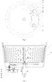
Fig. 1 is a stereoscopic view of a drainage structure mounted at the bottom of an inner tub of the present invention; -
Fig. 2 is a bottom view of a drainage structure mounted at the bottom of an inner tub of the present invention; -
Fig. 3 is a stereoscopic view of a drainage structure mounted at the bottom of an outer tub of the present invention; -
Fig. 4 is a top view ofFig. 3 of the present invention; -
Fig. 5 is a cutaway view ofFig. 3 of the present invention; -
Fig. 6 is a stereoscopic view of a first stop lever assembly and a second stop lever assembly of the present invention; and -
Fig. 7 is a cutaway view of a first stop lever assembly or a second stop lever assembly of the present invention. - 1-inner tub; 13-outer tub; 14-outer tub drainage outlet ; 15-groove structure; 16-first stop lever assembly; 17-second stop lever assembly; 18-pull rope; 19-traction motor; 20-press plate; 21-support; 22-pull rod; 23-stop lever; 24-nut; 25-sealing sleeve; 26-fixing disk; 27-compression spring; 28-fixed base; 29-stop nut; 30-first valve rod; 31-second valve rod; 32-hinge; and 33-ball valve.
- A washing machine drainage structure of the present invention is described in detail below in conjunction with the accompanying drawings.
- As shown in
Fig. 1 andFig. 2 , a washing machine drainage structure for a washing machine in which there is not water between an inner tub and an outer tub in washing and rinsing processes, is provided. The washing machine comprises aninner tub 1 without holes in the lower part of a tub side wall. The drainage structure comprises aball valve 33 and a driving device. A drainage outlet is arranged at a bottom wall of theinner tub 1, a water inlet end of theball valve 33 is communicated with the drainage outlet. Theball valve 33 is driven by the driving device to be closed in the washing and rinsing processes and opened in a draining procedure. - In the present invention, only the upper part of a side wall of the
inner tub 1 is provided with dehydration and drainage holes in a circle. The dehydration and drainage holes are arranged at positions above the maximum water level of the inner tub of the washing machine and are used for draining dehydrated water in a dehydrating process, and other parts of the side wall of theinner tub 1 are designed to be closed and are not provided with any through hole structure. Meanwhile, the drainage outlet with a larger aperture is arranged at the bottom wall of theinner tub 1. The drainage outlet is closed in the washing and rinsing processes and is opened in the draining process, and other parts of the bottom wall of theinner tub 1 are designed to be closed. - The ball valve is a valve in which a ball body with a circular channel serves as an open-close component and which is opened and closed as the ball body rotates along with valve rods. The open-close component of the ball valve is a ball body with a hole and rotates around an axial line vertical to the channel so as to achieve the purpose of opening and closing the channel. The ball valve is mainly used for opening and closing a pipeline and a device medium. Therefore, in the washing machine drainage structure provided by the present invention, the
ball valve 33 is mounted on the drainage outlet and is opened and closed by the driving device driving the valve rods of theball valve 33 according to the working principles of the ball valve. - The washing machine drainage structure of the present invention adopting the ball valve mainly has the following advantages:
- 1. the opening and closing operations can be frequently performed, and it is fast and light to open and close;
- 2. The fluid resistance during draining is small;
- 3.The ball valve has simple structure, relatively small volume, light weight, and is easy to maintain;
- 4. The sealing property is good;
- 5. The mounting direction of the ball valve is not limited, and the medium can flow in any directions; and
- 6. No vibration is caused, and noise is low.
- The drainage structure provided by the present invention is applicable to the washing machine in which there is not water between an inner tub and an outer tub in washing and rinsing processes. The drainage outlet is arranged at the bottom wall of the
inner tub 1, and theball valve 33 of the drainage structure is driven by the driving device to be closed in the washing and rinsing processes and opened in the draining process. Therefore, according to the drainage structure provided by the present invention, the ball valve is driven by the driving device to be closed or opened so as to close or open the drainage outlet , thereby implementing drainage. And the washing machine drainage structure provided by the present invention has a simple structure, is convenient to be mounted and is very valuable for market popularization. - As a preferred embodiment of the present invention, the
ball valve 33 comprises afirst valve rod 30 and asecond valve rod 31. The driving device drives thefirst valve rod 30 to rotate for 90 degrees to open theball valve 33, and the driving device drives thesecond valve rod 31 to reversely rotate for 90 degrees to close theball valve 33. - In the present invention, the
ball valve 33 comprises two valve rods for controlling the opening and closing of theball valve 33 respectively, so that theball valve 33 can be opened and closed by just controlling the driving device to control thefirst valve rod 30 and thesecond valve rod 31 to rotate. - Specifically, the
ball valve 33 comprises a valve casing and a ball body, the ball body is rotatably arranged in the valve casing, and thefirst valve rod 30 and thesecond valve rod 31 are connected respectively with the ball body of theball valve 33 through ahinge 32. - It is a key point of the present invention how to realize the rotation of the
first valve rod 30 and thesecond valve rod 31 of the present invention and then to open and close theball valve 33. Therefore, the present invention adopts the following technical solution to drive thefirst valve rod 30 and thesecond valve rod 31 to rotate. - As shown in
Fig. 1 ,Fig. 3 ,Fig. 4 and Fig. 5 , the washing machine comprises anouter tub 13 coaxially mounted outside the inner tub1. - In the present invention, the driving device comprises a first
stop lever assembly 16 and a secondstop lever assembly 17, both of which are mounted on the bottom wall of theouter tub 13. - The
first valve rod 30 is stopped by the firststop lever assembly 16 and rotates for 90 degrees in a reverse direction so as to open theball valve 33 when theinner tub 1 rotates in a forward direction, and thesecond valve rod 31 is stopped by the secondstop lever assembly 17 and rotates for 90 degrees in the forward direction so as to close theball valve 33 when theinner tub 1 rotates in the reverse direction. - In the present invention, the rotation in the forward direction or the reverse direction does not limit rotation of the
inner tub 1 in a constant direction, but only limits rotation of theinner tub 1 in two directions in the draining process. For example, when a clockwise direction is the forward direction, an anticlockwise direction is the reverse direction, vice versa. In the accompanying drawings of the present invention, theinner tub 1 rotates in the clockwise direction as the forward direction, and theinner tub 1 rotates in the anticlockwise direction as the reverse direction. In the present invention. Theinner tub 1 rotates in two directions in order to open theball valve 33 before draining and to close theball valve 33 after the draining is completed. - As a preferred embodiment of the present invention, each of the first
stop lever assembly 16 and the secondstop lever assembly 17 comprises astop lever 23 capable of moving upwards and downwards. The stop levers 23 of the firststop lever assembly 16 and the secondstop lever assembly 17 need to respectively act on thefirst valve rod 30 and thesecond valve rod 31. Theball valve 33 cannot be opened and closed if action objects are wrong. - Therefore, the first
stop lever assembly 16 is arranged outside the secondstop lever assembly 17. The length of thefirst valve rod 30 is larger than the length of thesecond valve rod 31, so that thestop lever 23 of the firststop lever assembly 16 only stops thefirst valve rod 30 when moving upwards. - In this way, the first
stop lever assembly 16 is arranged on the outer side of a free end of thesecond valve rod 31. The firststop lever assembly 16 cannot stop thesecond valve rod 31 and only can stop thefirst valve rod 30 when moving upwards. Thefirst valve rod 30 drives the channel of the ball body of theball valve 33 to be opened as being stopped by the firststop lever assembly 16, and theball valve 33 is opened. - The length of the
stop lever 23 of the secondstop lever assembly 17 is smaller than the length of thestop lever 23 of the firststop lever assembly 16. A distance between thesecond valve rod 31 and the bottom wall of theouter tub 13 is smaller than a distance between thefirst valve rod 30 and the bottom wall of theouter tub 13, so that thestop lever 23 of the secondstop lever assembly 17 only stops thesecond valve rod 31 when moving upwards. - In this way, the height of the
stop lever 23 of the secondstop lever assembly 17 moving upwards only can allow that thestop rod 23 of the secondstop rod assembly 17 to stop thesecond valve rod 31 rather than thefirst valve rod 30. Thesecond valve rod 31 drives the channel of the ball body of theball valve 33 to be closed as being stopped by thestop lever 23 of the secondstop lever assembly 17, and theball valve 33 is closed. - In the present invention, the lengths of the
first valve rod 30 and thesecond valve rod 31 meet: thefirst valve rod 30 rotates for 90 degrees in the reverse direction as being stopped by the firststop lever assembly 16 and then is separated from the firststop lever assembly 16, and thesecond valve rod 31 rotates for 90 degrees in the forward direction as being stopped by the secondstop lever assembly 17 and then is separated from the secondstop lever assembly 17. - In this way, the
ball valve 33 can be opened and closed only after thefirst valve rod 30 and thesecond valve rod 31 rotate to right positions. Besides, when theball valve 33 is opened and closed, thefirst valve rod 30 and thesecond valve rod 31 cannot rotate anymore after rotating to the right positions, and the firststop lever assembly 16 and the secondstop lever assembly 17 must be separated from thefirst valve rod 30 and thesecond valve rod 31 so as to not influence operation of the inner tub1. - Therefore, free ends of the
first valve rod 30 and thesecond valve rod 31 cannot extend out of the edge of theinner tub 1. - As shown in
Fig. 6 and Fig. 7 , in the present invention, each of the firststop lever assembly 16 and the secondstop lever assembly 17 comprises thestop lever 23, anut 24, a sealingsleeve 25, afixing disk 26 and acompression spring 27. The stop levers 23 pass through the bottom wall of theouter tub 13. In the present invention, the stop levers 23 of the firststop lever assembly 16 and the secondstop lever assembly 17 can move upwards and downwards in order to stop thefirst valve rod 30 and thesecond valve rod 31. The upper part of eachstop lever 23 is located between theinner tub 1 and theouter tub 13, and the lower part of eachstop lever 23 is located at the exterior of the bottom wall of theouter tub 13. The sealingsleeve 25 is set on the upper part of thecorresponding stop lever 23 and can extend and contract along with the movement of thecorresponding stop lever 23. One end of each sealingsleeve 25 is fixed on thecorresponding stop lever 23 through thenut 24, and the other end of each sealingsleeve 25 is fixed on the bottom wall of theouter tub 13 through the fixing disk in a sealed manner in order to keep sealing between the firststop lever assembly 16 and the secondstop lever assembly 17 and theouter tub 13 so as to prevent water leakage. - In the present invention, each
compression spring 27 is arranged at the lower part of thecorresponding stop lever 23. Astop nut 29 for stopping one end of eachcompression spring 27 is arranged at the lower end of thecorresponding stop lever 23. And eachcompression spring 27 is arranged between the bottom wall of theouter tub 13 and thecorresponding stop nut 29. - Further, a fixed
base 28 is mounted on theouter tub 13, the stop levers 23 pass through the fixedbase 28, and the compression springs 27 are arranged between the fixedbase 28 and the stop nuts 29, thereby preventing the compression springs 27 from pressing theouter tub 13 while being pressed so as to prevent damage to theouter tub 13 caused by frequent press. - In the present invention, the
ball valve 33 is mounted between theinner tub 1 and theouter tub 13. In order to provide enough space for mounting theball valve 33, agroove structure 15 is formed in the bottom wall of theouter tub 13. The firststop lever assembly 16 and the secondstop lever assembly 17 are mounted in thegroove structure 15, and thegroove structure 15 is provided with an outertub drainage outlet 14. - In the present invention, in order to implement the upwards and downwards movement of the first
stop lever assembly 16 and the secondstop lever assembly 17, as a preferred embodiment of the present invention, as shown inFig. 3 ,Fig. 4 and Fig. 5 , the driving device further comprises apress plate 20, asupport 21, apull rod 22 and atraction motor 19. Thesupport 21 is fixed on the outer side of the bottom wall of theouter tub 13, thepull rod 22 is rotatably mounted on thesupport 21, one end of thepull rod 22 is connected with thetraction motor 19, the other end of thepull rod 22 is fixedly connected with thepress plate 20, and two ends of thepress plate 20 press on the firststop lever assembly 16 and the secondstop lever assembly 17, respectively; thepull rod 22 and thepress plate 20 rotate around thesupport 21 under the traction of thetraction motor 19. When one end of thepress plate 20 moves upwards, the press plate presses the firststop lever assembly 16 to move upwards, the other end of thepress plate 20 moves downwards and then the secondstop lever assembly 17 moves downwards. - As a preferred embodiment of the present invention, the
traction motor 19 is connected with thepull rod 22 through apull rope 18. - What described above are only preferred embodiments of the present invention, but are not intended to limiting the scope of the present invention in any forms. Although the present invention has been disclosed in terms of preferred embodiment, it is not limited thereto. Without departing from the scope of the technical solution of the present invention, any persons skilled in the present invention can make equivalent embodiments with various alterations and modifications as equivalent variations by utilizing the above-mentioned technical contents. However, without departing from the contents of the technical solution of the present invention, any simple changes, equivalent variations and modifications made according to the technical essence of the present invention shall all be covered within the scope of the technical solution of the present invention.
Claims (10)
- A washing machine drainage structure for a washing machine in which there is not water between an inner tub and an outer tub in washing and rinsing processes, which comprises an inner tub (1) without holes in a lower part of a tub side wall,
comprising a ball valve (33) and a driving device,
a drainage outlet arranged at a bottom wall of the inner tub (1),
a water inlet end of the ball valve (33) being communicated with the drainage outlet, and
the ball valve (33) being driven by the driving device to be closed in the washing and rinsing processes and opened in a draining process. - The washing machine drainage structure according to claim 1, characterized in that the ball valve (33) comprises a first valve rod (30) and a second valve rod (31), the driving device drives the first valve rod (30) to rotate for 90 degrees to open the ball valve (33), and the driving device drives the second valve rod (31) to reversely rotate for 90 degrees to close the ball valve (33).
- The washing machine drainage structure according to claim 2, characterized in that the ball valve (33) comprises a valve casing and a ball body, the ball body is rotatably arranged in the valve casing,
the first valve rod (30) and the second valve rod (31) are connected respectively with the ball body of the ball valve (33) through a hinge (32). - The washing machine drainage structure according to claim 2 or 3, characterized in that, the washing machine comprises an outer tub (13) coaxially mounted outside the inner tub (1);
the driving device comprises a first stop lever assembly (16) and a second stop lever assembly (17), both of which are mounted on a bottom wall of the outer tub (13); and
the first valve rod (30) is stopped by the first stop lever assembly (16) and rotates for 90 degrees in a reverse direction so as to open the ball valve (33) when the inner tub (1) rotates in a forward direction, and
the second valve rod (31) is stopped by the second stop lever assembly (17) and rotates for 90 degrees in the forward direction so as to close the ball valve (33) when the inner tub (1) rotates in the reverse direction. - The washing machine drainage structure according to claim 4, characterized in that, the lengths of the first valve rod (30) and the second valve rod (31) allow that:the first valve rod (30) rotates for 90 degrees in the reverse direction as being stopped by the first stop lever assembly (16) and then is separated from the first stop lever assembly (16), andthe second valve rod (31) rotates for 90 degrees in the forward direction as being stopped by the second stop lever assembly (17) and then is separated from the second stop lever assembly (17).
- The washing machine drainage structure according to claim 4, characterized in that, each of the first stop lever assembly (16) and the second stop lever assembly (17) respectively comprises a stop lever (23) capable of moving upwards and downwards;
the first stop lever assembly (16) is arranged outside the second stop lever assembly (17), and a length of the first valve rod (30) is larger than a length of the second valve rod (31), so that the stop lever (23) of the first stop lever assembly (16) only stops the first valve rod (30) when moving upwards; and
the length of the stop lever (23) of the second stop lever assembly (17) is smaller than the length of the stop lever (23) of the first stop lever assembly (16), and a distance between the second valve rod (31) and the bottom wall of the outer tub (13) is smaller than a distance between the first valve rod (30) and the bottom wall of the outer tub (13), so that the stop lever (23) of the second stop lever assembly (17) only stops the second valve rod (31) when moving upwards. - The washing machine drainage structure according to claim 4, characterized in that, each of the first stop lever assembly (16) and the second stop lever assembly (17) comprises the stop lever (23), a nut (24), a sealing sleeve (25), a fixing disk (26) and a compression spring (27),
the stop levers (23) pass through the bottom wall of the outer tub (13), an upper part of each stop lever (23) is located between the inner tub (1) and the outer tub (13), a lower part of each stop lever (23) is located at an exterior of the bottom wall of the outer tub (13),
each sealing sleeve (25) is set on the upper part of the stop lever (23) and extends and contracts along with the movement of the stop lever (23),
one end of each sealing sleeve (25) is fixed on the stop lever (23) through the nut (24), and the other end of each sealing sleeve (25) is fixed on the bottom wall of the outer tub (13) through the fixing disk (26) in a sealed manner; and each compression spring (27) is set around the lower part of the stop lever (23). - The washing machine drainage structure according to claim 7, characterized in that, a stop nut (29) for stopping one end of each compression spring (27) is arranged at a lower end of the stop lever (23), and each compression spring (27) is arranged between the bottom wall of the outer tub (13) and the stop nut (29).
- The washing machine drainage structure according to claim 4, characterized in that, the bottom wall of the outer tub (13) is provided with a groove structure (15), the first stop lever assembly (16) and the second stop lever assembly (17) are mounted in the groove structure (15), and the groove structure (15) is provided with an outer tub drainage outlet (14).
- The washing machine drainage structure according to claim 4, characterized in that, the driving device further comprises a press plate (20), a support (21), a pull rod (22) and a traction motor (19),
the support (21) is fixed on an outer side of the bottom wall of the outer tub (13),
the pull rod (22) is rotatably mounted on the support (21), one end of the pull rod (22) is connected with the traction motor (19), the other end of the pull rod (22) is fixedly connected with the press plate (20), and two ends of the press plate (20) press on the first stop lever assembly (16) and the second stop lever assembly (17) respectively; and
the pull rod (22) and the press plate (20) rotate around the support (21) under the traction of the traction motor (19),
when one end of the press plate (20) moves upwards, the press plate presses the first stop lever assembly (16) to move upwards, and the other end of the press plate (20) moves downwards and then the second stop lever assembly (17) moves downwards.
Applications Claiming Priority (2)
| Application Number | Priority Date | Filing Date | Title |
|---|---|---|---|
| CN201510079419.5A CN105986430B (en) | 2015-02-13 | 2015-02-13 | Drainage structure of a washing machine |
| PCT/CN2015/095293 WO2016127686A1 (en) | 2015-02-13 | 2015-11-23 | Drainage structure for washing machine |
Publications (3)
| Publication Number | Publication Date |
|---|---|
| EP3258001A1 true EP3258001A1 (en) | 2017-12-20 |
| EP3258001A4 EP3258001A4 (en) | 2018-10-31 |
| EP3258001B1 EP3258001B1 (en) | 2022-01-12 |
Family
ID=56615340
Family Applications (1)
| Application Number | Title | Priority Date | Filing Date |
|---|---|---|---|
| EP15881835.1A Not-in-force EP3258001B1 (en) | 2015-02-13 | 2015-11-23 | Drainage structure for washing machine |
Country Status (6)
| Country | Link |
|---|---|
| US (1) | US10550507B2 (en) |
| EP (1) | EP3258001B1 (en) |
| JP (1) | JP6614511B2 (en) |
| KR (1) | KR20170117146A (en) |
| CN (1) | CN105986430B (en) |
| WO (1) | WO2016127686A1 (en) |
Families Citing this family (21)
| Publication number | Priority date | Publication date | Assignee | Title |
|---|---|---|---|---|
| CN107794693A (en) * | 2016-09-06 | 2018-03-13 | 青岛海尔洗衣机有限公司 | Anhydrous washing machine between a kind of interior outer barrel |
| CN106521867B (en) * | 2016-12-09 | 2018-11-23 | 熊文 | Washing machine with imperforate inner barrel |
| CN107904853B (en) * | 2017-11-13 | 2020-04-14 | 无锡小天鹅电器有限公司 | Washing machine and drainage mechanism thereof |
| CN109868615B (en) * | 2017-12-01 | 2022-07-12 | 青岛海尔洗衣机有限公司 | Washing machine |
| CN110409111B (en) * | 2018-04-28 | 2025-10-28 | 青岛海尔洗衣机有限公司 | Clothing processing equipment |
| CN110924048B (en) * | 2018-09-17 | 2023-02-17 | 青岛海尔洗衣机有限公司 | Control method of washing machine |
| CN110904636B (en) * | 2018-09-17 | 2023-04-11 | 青岛海尔洗衣机有限公司 | Drainage device of washing machine, washing machine and control method of washing machine |
| CN110904637B (en) * | 2018-09-17 | 2023-02-17 | 青岛海尔洗衣机有限公司 | Washing machine's drainage device and washing machine |
| CN111074488B (en) * | 2018-10-19 | 2022-08-02 | 无锡小天鹅电器有限公司 | Washing machine |
| CN111155264B (en) * | 2018-10-19 | 2022-03-22 | 无锡小天鹅电器有限公司 | Washing machine |
| JP7293388B2 (en) * | 2019-03-13 | 2023-06-19 | 青島海爾滾筒洗衣机有限公司 | drum washing machine |
| CN112195620B (en) * | 2019-06-19 | 2022-09-23 | 重庆海尔滚筒洗衣机有限公司 | Drum washing machine and control method thereof |
| CN110924072B (en) * | 2019-11-25 | 2021-02-19 | 华南理工大学 | Riding type body-building washing machine |
| CN114246517B (en) * | 2020-09-24 | 2023-01-31 | 尚科宁家(中国)科技有限公司 | A ground cleaning system and automatic cleaning method thereof |
| CN113638199B (en) * | 2020-04-27 | 2023-08-29 | 青岛海尔洗衣机有限公司 | Washing machine |
| CN114197147B (en) * | 2020-08-27 | 2023-02-03 | 无锡小天鹅电器有限公司 | Clothes treatment equipment |
| CN114318776B (en) * | 2020-09-30 | 2024-09-13 | 青岛海尔洗衣机有限公司 | Washing machine and control method thereof |
| CN115264155A (en) * | 2021-04-29 | 2022-11-01 | 尚科宁家(中国)科技有限公司 | Cleaning system |
| CN116791326A (en) * | 2022-03-15 | 2023-09-22 | 青岛胶州海尔洗涤电器有限公司 | Lifting device for drum washing machine and drum washing machine |
| CN115058862B (en) * | 2022-07-01 | 2024-10-25 | 无锡小天鹅电器有限公司 | Clothes treatment equipment and control method |
| CN115058860B (en) * | 2022-07-01 | 2025-11-14 | 无锡小天鹅电器有限公司 | Clothes treatment equipment |
Family Cites Families (15)
| Publication number | Priority date | Publication date | Assignee | Title |
|---|---|---|---|---|
| US2016635A (en) * | 1934-04-04 | 1935-10-08 | Henn William August | Flush tank |
| JPS4718951Y1 (en) * | 1969-10-03 | 1972-06-29 | ||
| JPH03284295A (en) * | 1990-03-30 | 1991-12-13 | Toshiba Corp | Washing machine |
| JPH03284294A (en) | 1990-03-30 | 1991-12-13 | Toshiba Corp | Washing machine |
| DE4024169A1 (en) * | 1990-07-30 | 1992-02-06 | Buschjost Gmbh & Co Fr | Valve unit for opening and closing outlet of liq. container - for washing soln. etc. of (dish) washing machine, with sealing ring pressed against sealing body |
| JPH0928985A (en) | 1995-07-25 | 1997-02-04 | Toshiba Corp | Fully automatic washing machine |
| KR19980031289U (en) * | 1996-11-30 | 1998-08-17 | 배순훈 | Washing and draining device of washing machine |
| CN2595841Y (en) * | 2002-11-29 | 2003-12-31 | 金羚电器有限公司 | Washing machine with regulatable water discharge speed |
| CN2614216Y (en) * | 2003-03-10 | 2004-05-05 | 董汇茹 | Water-saving washing machine drainage device |
| JP2005230413A (en) * | 2004-02-23 | 2005-09-02 | Mitsubishi Material Cmi Kk | Drain valve of washing machine |
| ES2378921B1 (en) * | 2009-10-08 | 2013-03-19 | Bsh Electrodomésticos España, S.A. | DRAIN VALVE FOR DRAIN HOLE OF WASHING MACHINE WASHING MACHINE AND WASHING MACHINE WITH SAID DRAIN VALVE. |
| KR20130016932A (en) * | 2011-08-09 | 2013-02-19 | 삼성전자주식회사 | Washing machine |
| CN103898708B (en) * | 2012-12-27 | 2018-02-23 | 青岛海尔洗衣机有限公司 | A kind of electromagnetic type drainage system and washing machine |
| CN203238457U (en) * | 2013-04-27 | 2013-10-16 | 松下家电研究开发(杭州)有限公司 | Washing machine |
| JP2015029546A (en) | 2013-07-31 | 2015-02-16 | 株式会社東芝 | Washing machine |
-
2015
- 2015-02-13 CN CN201510079419.5A patent/CN105986430B/en active Active
- 2015-11-23 WO PCT/CN2015/095293 patent/WO2016127686A1/en not_active Ceased
- 2015-11-23 JP JP2017541611A patent/JP6614511B2/en active Active
- 2015-11-23 US US15/550,589 patent/US10550507B2/en active Active
- 2015-11-23 EP EP15881835.1A patent/EP3258001B1/en not_active Not-in-force
- 2015-11-23 KR KR1020177025464A patent/KR20170117146A/en not_active Ceased
Also Published As
| Publication number | Publication date |
|---|---|
| JP6614511B2 (en) | 2019-12-04 |
| WO2016127686A1 (en) | 2016-08-18 |
| JP2018508272A (en) | 2018-03-29 |
| KR20170117146A (en) | 2017-10-20 |
| US10550507B2 (en) | 2020-02-04 |
| CN105986430B (en) | 2019-08-27 |
| US20180030641A1 (en) | 2018-02-01 |
| EP3258001B1 (en) | 2022-01-12 |
| EP3258001A4 (en) | 2018-10-31 |
| CN105986430A (en) | 2016-10-05 |
Similar Documents
| Publication | Publication Date | Title |
|---|---|---|
| EP3258001A1 (en) | Drainage structure for washing machine | |
| CN103898708B (en) | A kind of electromagnetic type drainage system and washing machine | |
| US10584439B2 (en) | Drainage mechanism of a washing machine | |
| CN104452184B (en) | Water saving washing machine | |
| CN105568616B (en) | A kind of non-porous interior barrel washing machine | |
| US20200149208A1 (en) | Draining structure of a washing machine | |
| CN108796962A (en) | A kind of washing machine | |
| CN108796997A (en) | A kind of washing machine | |
| CN106544818B (en) | Environment-friendly water-saving working method of washing machine and washing machine | |
| JP2020518341A (en) | Washing machine drainage structure and drainage method | |
| CN105986404B (en) | Automatic closed water-saving washing machine | |
| CN108625346A (en) | A kind of hydraulic engineering penstock shutter draft gear | |
| CN203213235U (en) | Electronically-controlled water drainer | |
| CN207143532U (en) | A kind of double-shaft concentric separation type drive mechanism and the washing machine being made up of it | |
| CN103343558A (en) | Electrically controlled drainage device | |
| CN201671153U (en) | Toilet integrated cabinet | |
| CN204610849U (en) | A kind of jacketed type stop valve installation | |
| CN205663582U (en) | Pressurized -water structure and pressurized -water device that has this structure | |
| CN114561780A (en) | A washing machine and its control method | |
| CN207295261U (en) | It is a kind of that there is the circular water discharging pump of switch valve | |
| CN204459303U (en) | Heavy caliber slope block-type safety check | |
| CN222255166U (en) | Double-open flap valve | |
| CN204901003U (en) | Automatic launching gear and contain device's basin | |
| CN206130249U (en) | Electric control water valve | |
| CN206299529U (en) | A kind of Novel manual pump |
Legal Events
| Date | Code | Title | Description |
|---|---|---|---|
| STAA | Information on the status of an ep patent application or granted ep patent |
Free format text: STATUS: THE INTERNATIONAL PUBLICATION HAS BEEN MADE |
|
| PUAI | Public reference made under article 153(3) epc to a published international application that has entered the european phase |
Free format text: ORIGINAL CODE: 0009012 |
|
| STAA | Information on the status of an ep patent application or granted ep patent |
Free format text: STATUS: REQUEST FOR EXAMINATION WAS MADE |
|
| 17P | Request for examination filed |
Effective date: 20170901 |
|
| AK | Designated contracting states |
Kind code of ref document: A1 Designated state(s): AL AT BE BG CH CY CZ DE DK EE ES FI FR GB GR HR HU IE IS IT LI LT LU LV MC MK MT NL NO PL PT RO RS SE SI SK SM TR |
|
| AX | Request for extension of the european patent |
Extension state: BA ME |
|
| DAV | Request for validation of the european patent (deleted) | ||
| DAX | Request for extension of the european patent (deleted) | ||
| A4 | Supplementary search report drawn up and despatched |
Effective date: 20181004 |
|
| RIC1 | Information provided on ipc code assigned before grant |
Ipc: D06F 37/12 20060101ALN20180925BHEP Ipc: D06F 23/04 20060101ALN20180925BHEP Ipc: F16K 31/44 20060101ALN20180925BHEP Ipc: D06F 39/08 20060101AFI20180925BHEP Ipc: F16K 15/04 20060101ALN20180925BHEP |
|
| RIC1 | Information provided on ipc code assigned before grant |
Ipc: D06F 39/08 20060101AFI20210623BHEP Ipc: D06F 23/04 20060101ALN20210623BHEP Ipc: D06F 37/12 20060101ALN20210623BHEP Ipc: F16K 31/44 20060101ALN20210623BHEP Ipc: F16K 15/04 20060101ALN20210623BHEP |
|
| GRAP | Despatch of communication of intention to grant a patent |
Free format text: ORIGINAL CODE: EPIDOSNIGR1 |
|
| STAA | Information on the status of an ep patent application or granted ep patent |
Free format text: STATUS: GRANT OF PATENT IS INTENDED |
|
| RIC1 | Information provided on ipc code assigned before grant |
Ipc: D06F 39/08 20060101AFI20210716BHEP Ipc: D06F 23/04 20060101ALN20210716BHEP Ipc: D06F 37/12 20060101ALN20210716BHEP Ipc: F16K 31/44 20060101ALN20210716BHEP Ipc: F16K 15/04 20060101ALN20210716BHEP |
|
| INTG | Intention to grant announced |
Effective date: 20210806 |
|
| GRAS | Grant fee paid |
Free format text: ORIGINAL CODE: EPIDOSNIGR3 |
|
| GRAA | (expected) grant |
Free format text: ORIGINAL CODE: 0009210 |
|
| STAA | Information on the status of an ep patent application or granted ep patent |
Free format text: STATUS: THE PATENT HAS BEEN GRANTED |
|
| AK | Designated contracting states |
Kind code of ref document: B1 Designated state(s): AL AT BE BG CH CY CZ DE DK EE ES FI FR GB GR HR HU IE IS IT LI LT LU LV MC MK MT NL NO PL PT RO RS SE SI SK SM TR |
|
| REG | Reference to a national code |
Ref country code: GB Ref legal event code: FG4D |
|
| REG | Reference to a national code |
Ref country code: CH Ref legal event code: EP |
|
| REG | Reference to a national code |
Ref country code: DE Ref legal event code: R096 Ref document number: 602015076486 Country of ref document: DE |
|
| REG | Reference to a national code |
Ref country code: IE Ref legal event code: FG4D |
|
| REG | Reference to a national code |
Ref country code: AT Ref legal event code: REF Ref document number: 1462460 Country of ref document: AT Kind code of ref document: T Effective date: 20220215 |
|
| REG | Reference to a national code |
Ref country code: LT Ref legal event code: MG9D |
|
| REG | Reference to a national code |
Ref country code: NL Ref legal event code: MP Effective date: 20220112 |
|
| REG | Reference to a national code |
Ref country code: AT Ref legal event code: MK05 Ref document number: 1462460 Country of ref document: AT Kind code of ref document: T Effective date: 20220112 |
|
| PG25 | Lapsed in a contracting state [announced via postgrant information from national office to epo] |
Ref country code: NL Free format text: LAPSE BECAUSE OF FAILURE TO SUBMIT A TRANSLATION OF THE DESCRIPTION OR TO PAY THE FEE WITHIN THE PRESCRIBED TIME-LIMIT Effective date: 20220112 |
|
| PG25 | Lapsed in a contracting state [announced via postgrant information from national office to epo] |
Ref country code: SE Free format text: LAPSE BECAUSE OF FAILURE TO SUBMIT A TRANSLATION OF THE DESCRIPTION OR TO PAY THE FEE WITHIN THE PRESCRIBED TIME-LIMIT Effective date: 20220112 Ref country code: RS Free format text: LAPSE BECAUSE OF FAILURE TO SUBMIT A TRANSLATION OF THE DESCRIPTION OR TO PAY THE FEE WITHIN THE PRESCRIBED TIME-LIMIT Effective date: 20220112 Ref country code: PT Free format text: LAPSE BECAUSE OF FAILURE TO SUBMIT A TRANSLATION OF THE DESCRIPTION OR TO PAY THE FEE WITHIN THE PRESCRIBED TIME-LIMIT Effective date: 20220512 Ref country code: NO Free format text: LAPSE BECAUSE OF FAILURE TO SUBMIT A TRANSLATION OF THE DESCRIPTION OR TO PAY THE FEE WITHIN THE PRESCRIBED TIME-LIMIT Effective date: 20220412 Ref country code: LT Free format text: LAPSE BECAUSE OF FAILURE TO SUBMIT A TRANSLATION OF THE DESCRIPTION OR TO PAY THE FEE WITHIN THE PRESCRIBED TIME-LIMIT Effective date: 20220112 Ref country code: HR Free format text: LAPSE BECAUSE OF FAILURE TO SUBMIT A TRANSLATION OF THE DESCRIPTION OR TO PAY THE FEE WITHIN THE PRESCRIBED TIME-LIMIT Effective date: 20220112 Ref country code: ES Free format text: LAPSE BECAUSE OF FAILURE TO SUBMIT A TRANSLATION OF THE DESCRIPTION OR TO PAY THE FEE WITHIN THE PRESCRIBED TIME-LIMIT Effective date: 20220112 Ref country code: BG Free format text: LAPSE BECAUSE OF FAILURE TO SUBMIT A TRANSLATION OF THE DESCRIPTION OR TO PAY THE FEE WITHIN THE PRESCRIBED TIME-LIMIT Effective date: 20220412 |
|
| PG25 | Lapsed in a contracting state [announced via postgrant information from national office to epo] |
Ref country code: PL Free format text: LAPSE BECAUSE OF FAILURE TO SUBMIT A TRANSLATION OF THE DESCRIPTION OR TO PAY THE FEE WITHIN THE PRESCRIBED TIME-LIMIT Effective date: 20220112 Ref country code: LV Free format text: LAPSE BECAUSE OF FAILURE TO SUBMIT A TRANSLATION OF THE DESCRIPTION OR TO PAY THE FEE WITHIN THE PRESCRIBED TIME-LIMIT Effective date: 20220112 Ref country code: GR Free format text: LAPSE BECAUSE OF FAILURE TO SUBMIT A TRANSLATION OF THE DESCRIPTION OR TO PAY THE FEE WITHIN THE PRESCRIBED TIME-LIMIT Effective date: 20220413 Ref country code: FI Free format text: LAPSE BECAUSE OF FAILURE TO SUBMIT A TRANSLATION OF THE DESCRIPTION OR TO PAY THE FEE WITHIN THE PRESCRIBED TIME-LIMIT Effective date: 20220112 Ref country code: AT Free format text: LAPSE BECAUSE OF FAILURE TO SUBMIT A TRANSLATION OF THE DESCRIPTION OR TO PAY THE FEE WITHIN THE PRESCRIBED TIME-LIMIT Effective date: 20220112 |
|
| PG25 | Lapsed in a contracting state [announced via postgrant information from national office to epo] |
Ref country code: IS Free format text: LAPSE BECAUSE OF FAILURE TO SUBMIT A TRANSLATION OF THE DESCRIPTION OR TO PAY THE FEE WITHIN THE PRESCRIBED TIME-LIMIT Effective date: 20220512 |
|
| REG | Reference to a national code |
Ref country code: DE Ref legal event code: R097 Ref document number: 602015076486 Country of ref document: DE |
|
| PG25 | Lapsed in a contracting state [announced via postgrant information from national office to epo] |
Ref country code: SM Free format text: LAPSE BECAUSE OF FAILURE TO SUBMIT A TRANSLATION OF THE DESCRIPTION OR TO PAY THE FEE WITHIN THE PRESCRIBED TIME-LIMIT Effective date: 20220112 Ref country code: SK Free format text: LAPSE BECAUSE OF FAILURE TO SUBMIT A TRANSLATION OF THE DESCRIPTION OR TO PAY THE FEE WITHIN THE PRESCRIBED TIME-LIMIT Effective date: 20220112 Ref country code: RO Free format text: LAPSE BECAUSE OF FAILURE TO SUBMIT A TRANSLATION OF THE DESCRIPTION OR TO PAY THE FEE WITHIN THE PRESCRIBED TIME-LIMIT Effective date: 20220112 Ref country code: EE Free format text: LAPSE BECAUSE OF FAILURE TO SUBMIT A TRANSLATION OF THE DESCRIPTION OR TO PAY THE FEE WITHIN THE PRESCRIBED TIME-LIMIT Effective date: 20220112 Ref country code: DK Free format text: LAPSE BECAUSE OF FAILURE TO SUBMIT A TRANSLATION OF THE DESCRIPTION OR TO PAY THE FEE WITHIN THE PRESCRIBED TIME-LIMIT Effective date: 20220112 Ref country code: CZ Free format text: LAPSE BECAUSE OF FAILURE TO SUBMIT A TRANSLATION OF THE DESCRIPTION OR TO PAY THE FEE WITHIN THE PRESCRIBED TIME-LIMIT Effective date: 20220112 |
|
| PLBE | No opposition filed within time limit |
Free format text: ORIGINAL CODE: 0009261 |
|
| STAA | Information on the status of an ep patent application or granted ep patent |
Free format text: STATUS: NO OPPOSITION FILED WITHIN TIME LIMIT |
|
| PG25 | Lapsed in a contracting state [announced via postgrant information from national office to epo] |
Ref country code: AL Free format text: LAPSE BECAUSE OF FAILURE TO SUBMIT A TRANSLATION OF THE DESCRIPTION OR TO PAY THE FEE WITHIN THE PRESCRIBED TIME-LIMIT Effective date: 20220112 |
|
| 26N | No opposition filed |
Effective date: 20221013 |
|
| PG25 | Lapsed in a contracting state [announced via postgrant information from national office to epo] |
Ref country code: SI Free format text: LAPSE BECAUSE OF FAILURE TO SUBMIT A TRANSLATION OF THE DESCRIPTION OR TO PAY THE FEE WITHIN THE PRESCRIBED TIME-LIMIT Effective date: 20220112 |
|
| REG | Reference to a national code |
Ref country code: DE Ref legal event code: R119 Ref document number: 602015076486 Country of ref document: DE |
|
| PG25 | Lapsed in a contracting state [announced via postgrant information from national office to epo] |
Ref country code: MC Free format text: LAPSE BECAUSE OF FAILURE TO SUBMIT A TRANSLATION OF THE DESCRIPTION OR TO PAY THE FEE WITHIN THE PRESCRIBED TIME-LIMIT Effective date: 20220112 |
|
| REG | Reference to a national code |
Ref country code: CH Ref legal event code: PL |
|
| GBPC | Gb: european patent ceased through non-payment of renewal fee |
Effective date: 20221123 |
|
| REG | Reference to a national code |
Ref country code: BE Ref legal event code: MM Effective date: 20221130 |
|
| PG25 | Lapsed in a contracting state [announced via postgrant information from national office to epo] |
Ref country code: LI Free format text: LAPSE BECAUSE OF NON-PAYMENT OF DUE FEES Effective date: 20221130 Ref country code: CH Free format text: LAPSE BECAUSE OF NON-PAYMENT OF DUE FEES Effective date: 20221130 |
|
| PG25 | Lapsed in a contracting state [announced via postgrant information from national office to epo] |
Ref country code: LU Free format text: LAPSE BECAUSE OF NON-PAYMENT OF DUE FEES Effective date: 20221123 |
|
| PG25 | Lapsed in a contracting state [announced via postgrant information from national office to epo] |
Ref country code: IT Free format text: LAPSE BECAUSE OF NON-PAYMENT OF DUE FEES Effective date: 20221123 Ref country code: IE Free format text: LAPSE BECAUSE OF NON-PAYMENT OF DUE FEES Effective date: 20221123 Ref country code: GB Free format text: LAPSE BECAUSE OF NON-PAYMENT OF DUE FEES Effective date: 20221123 Ref country code: DE Free format text: LAPSE BECAUSE OF NON-PAYMENT OF DUE FEES Effective date: 20230601 |
|
| PG25 | Lapsed in a contracting state [announced via postgrant information from national office to epo] |
Ref country code: FR Free format text: LAPSE BECAUSE OF NON-PAYMENT OF DUE FEES Effective date: 20221130 Ref country code: BE Free format text: LAPSE BECAUSE OF NON-PAYMENT OF DUE FEES Effective date: 20221130 |
|
| PG25 | Lapsed in a contracting state [announced via postgrant information from national office to epo] |
Ref country code: HU Free format text: LAPSE BECAUSE OF FAILURE TO SUBMIT A TRANSLATION OF THE DESCRIPTION OR TO PAY THE FEE WITHIN THE PRESCRIBED TIME-LIMIT; INVALID AB INITIO Effective date: 20151123 |
|
| PG25 | Lapsed in a contracting state [announced via postgrant information from national office to epo] |
Ref country code: CY Free format text: LAPSE BECAUSE OF FAILURE TO SUBMIT A TRANSLATION OF THE DESCRIPTION OR TO PAY THE FEE WITHIN THE PRESCRIBED TIME-LIMIT Effective date: 20220112 |
|
| PG25 | Lapsed in a contracting state [announced via postgrant information from national office to epo] |
Ref country code: MK Free format text: LAPSE BECAUSE OF FAILURE TO SUBMIT A TRANSLATION OF THE DESCRIPTION OR TO PAY THE FEE WITHIN THE PRESCRIBED TIME-LIMIT Effective date: 20220112 |
|
| PG25 | Lapsed in a contracting state [announced via postgrant information from national office to epo] |
Ref country code: MT Free format text: LAPSE BECAUSE OF FAILURE TO SUBMIT A TRANSLATION OF THE DESCRIPTION OR TO PAY THE FEE WITHIN THE PRESCRIBED TIME-LIMIT Effective date: 20220112 |
|
| PG25 | Lapsed in a contracting state [announced via postgrant information from national office to epo] |
Ref country code: TR Free format text: LAPSE BECAUSE OF FAILURE TO SUBMIT A TRANSLATION OF THE DESCRIPTION OR TO PAY THE FEE WITHIN THE PRESCRIBED TIME-LIMIT Effective date: 20220112 |