EP3257771A1 - Pour spout stopper and packaging container - Google Patents
Pour spout stopper and packaging container Download PDFInfo
- Publication number
- EP3257771A1 EP3257771A1 EP16771776.8A EP16771776A EP3257771A1 EP 3257771 A1 EP3257771 A1 EP 3257771A1 EP 16771776 A EP16771776 A EP 16771776A EP 3257771 A1 EP3257771 A1 EP 3257771A1
- Authority
- EP
- European Patent Office
- Prior art keywords
- pour spout
- flange
- sidewall
- recess
- spout according
- Prior art date
- Legal status (The legal status is an assumption and is not a legal conclusion. Google has not performed a legal analysis and makes no representation as to the accuracy of the status listed.)
- Withdrawn
Links
Images








Classifications
-
- B—PERFORMING OPERATIONS; TRANSPORTING
- B65—CONVEYING; PACKING; STORING; HANDLING THIN OR FILAMENTARY MATERIAL
- B65D—CONTAINERS FOR STORAGE OR TRANSPORT OF ARTICLES OR MATERIALS, e.g. BAGS, BARRELS, BOTTLES, BOXES, CANS, CARTONS, CRATES, DRUMS, JARS, TANKS, HOPPERS, FORWARDING CONTAINERS; ACCESSORIES, CLOSURES, OR FITTINGS THEREFOR; PACKAGING ELEMENTS; PACKAGES
- B65D5/00—Rigid or semi-rigid containers of polygonal cross-section, e.g. boxes, cartons or trays, formed by folding or erecting one or more blanks made of paper
- B65D5/42—Details of containers or of foldable or erectable container blanks
- B65D5/72—Contents-dispensing means
- B65D5/74—Spouts
- B65D5/746—Spouts formed separately from the container
-
- B—PERFORMING OPERATIONS; TRANSPORTING
- B65—CONVEYING; PACKING; STORING; HANDLING THIN OR FILAMENTARY MATERIAL
- B65D—CONTAINERS FOR STORAGE OR TRANSPORT OF ARTICLES OR MATERIALS, e.g. BAGS, BARRELS, BOTTLES, BOXES, CANS, CARTONS, CRATES, DRUMS, JARS, TANKS, HOPPERS, FORWARDING CONTAINERS; ACCESSORIES, CLOSURES, OR FITTINGS THEREFOR; PACKAGING ELEMENTS; PACKAGES
- B65D47/00—Closures with filling and discharging, or with discharging, devices
- B65D47/04—Closures with discharging devices other than pumps
- B65D47/06—Closures with discharging devices other than pumps with pouring spouts or tubes; with discharge nozzles or passages
- B65D47/10—Closures with discharging devices other than pumps with pouring spouts or tubes; with discharge nozzles or passages having frangible closures
- B65D47/103—Membranes with a tearing element
-
- B—PERFORMING OPERATIONS; TRANSPORTING
- B65—CONVEYING; PACKING; STORING; HANDLING THIN OR FILAMENTARY MATERIAL
- B65D—CONTAINERS FOR STORAGE OR TRANSPORT OF ARTICLES OR MATERIALS, e.g. BAGS, BARRELS, BOTTLES, BOXES, CANS, CARTONS, CRATES, DRUMS, JARS, TANKS, HOPPERS, FORWARDING CONTAINERS; ACCESSORIES, CLOSURES, OR FITTINGS THEREFOR; PACKAGING ELEMENTS; PACKAGES
- B65D47/00—Closures with filling and discharging, or with discharging, devices
- B65D47/36—Closures with frangible parts adapted to be pierced, torn or removed, to provide discharge openings
-
- B—PERFORMING OPERATIONS; TRANSPORTING
- B65—CONVEYING; PACKING; STORING; HANDLING THIN OR FILAMENTARY MATERIAL
- B65D—CONTAINERS FOR STORAGE OR TRANSPORT OF ARTICLES OR MATERIALS, e.g. BAGS, BARRELS, BOTTLES, BOXES, CANS, CARTONS, CRATES, DRUMS, JARS, TANKS, HOPPERS, FORWARDING CONTAINERS; ACCESSORIES, CLOSURES, OR FITTINGS THEREFOR; PACKAGING ELEMENTS; PACKAGES
- B65D5/00—Rigid or semi-rigid containers of polygonal cross-section, e.g. boxes, cartons or trays, formed by folding or erecting one or more blanks made of paper
- B65D5/02—Rigid or semi-rigid containers of polygonal cross-section, e.g. boxes, cartons or trays, formed by folding or erecting one or more blanks made of paper by folding or erecting a single blank to form a tubular body with or without subsequent folding operations, or the addition of separate elements, to close the ends of the body
- B65D5/06—Rigid or semi-rigid containers of polygonal cross-section, e.g. boxes, cartons or trays, formed by folding or erecting one or more blanks made of paper by folding or erecting a single blank to form a tubular body with or without subsequent folding operations, or the addition of separate elements, to close the ends of the body with end-closing or contents-supporting elements formed by folding inwardly a wall extending from, and continuously around, an end of the tubular body
- B65D5/067—Gable-top containers
-
- B—PERFORMING OPERATIONS; TRANSPORTING
- B65—CONVEYING; PACKING; STORING; HANDLING THIN OR FILAMENTARY MATERIAL
- B65D—CONTAINERS FOR STORAGE OR TRANSPORT OF ARTICLES OR MATERIALS, e.g. BAGS, BARRELS, BOTTLES, BOXES, CANS, CARTONS, CRATES, DRUMS, JARS, TANKS, HOPPERS, FORWARDING CONTAINERS; ACCESSORIES, CLOSURES, OR FITTINGS THEREFOR; PACKAGING ELEMENTS; PACKAGES
- B65D5/00—Rigid or semi-rigid containers of polygonal cross-section, e.g. boxes, cartons or trays, formed by folding or erecting one or more blanks made of paper
- B65D5/40—Rigid or semi-rigid containers of polygonal cross-section, e.g. boxes, cartons or trays, formed by folding or erecting one or more blanks made of paper specially constructed to contain liquids
-
- B—PERFORMING OPERATIONS; TRANSPORTING
- B65—CONVEYING; PACKING; STORING; HANDLING THIN OR FILAMENTARY MATERIAL
- B65D—CONTAINERS FOR STORAGE OR TRANSPORT OF ARTICLES OR MATERIALS, e.g. BAGS, BARRELS, BOTTLES, BOXES, CANS, CARTONS, CRATES, DRUMS, JARS, TANKS, HOPPERS, FORWARDING CONTAINERS; ACCESSORIES, CLOSURES, OR FITTINGS THEREFOR; PACKAGING ELEMENTS; PACKAGES
- B65D5/00—Rigid or semi-rigid containers of polygonal cross-section, e.g. boxes, cartons or trays, formed by folding or erecting one or more blanks made of paper
- B65D5/42—Details of containers or of foldable or erectable container blanks
- B65D5/72—Contents-dispensing means
- B65D5/74—Spouts
-
- B—PERFORMING OPERATIONS; TRANSPORTING
- B65—CONVEYING; PACKING; STORING; HANDLING THIN OR FILAMENTARY MATERIAL
- B65D—CONTAINERS FOR STORAGE OR TRANSPORT OF ARTICLES OR MATERIALS, e.g. BAGS, BARRELS, BOTTLES, BOXES, CANS, CARTONS, CRATES, DRUMS, JARS, TANKS, HOPPERS, FORWARDING CONTAINERS; ACCESSORIES, CLOSURES, OR FITTINGS THEREFOR; PACKAGING ELEMENTS; PACKAGES
- B65D51/00—Closures not otherwise provided for
- B65D51/18—Arrangements of closures with protective outer cap-like covers or of two or more co-operating closures
- B65D51/20—Caps, lids, or covers co-operating with an inner closure arranged to be opened by piercing, cutting, or tearing
-
- B—PERFORMING OPERATIONS; TRANSPORTING
- B65—CONVEYING; PACKING; STORING; HANDLING THIN OR FILAMENTARY MATERIAL
- B65D—CONTAINERS FOR STORAGE OR TRANSPORT OF ARTICLES OR MATERIALS, e.g. BAGS, BARRELS, BOTTLES, BOXES, CANS, CARTONS, CRATES, DRUMS, JARS, TANKS, HOPPERS, FORWARDING CONTAINERS; ACCESSORIES, CLOSURES, OR FITTINGS THEREFOR; PACKAGING ELEMENTS; PACKAGES
- B65D43/00—Lids or covers for rigid or semi-rigid containers
Definitions
- the present invention relates to a pour spout and a packaging container with the pour spout.
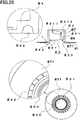
- Packaging containers having a container body with a pour spout such as that shown in Fig. 25 .
- the container body is formed as follows: a sheet material is formed by laminating a barrier layer (such as an aluminum foil, aluminum deposited film, or inorganic deposited oxide film) between a paper substrate layer and a sealant layer of thermoplastic resin (see PTL 1), the sheet material is folded into a box-like shape, edges of the sheet material are overlapped, followed by sealing.
- a barrier layer such as an aluminum foil, aluminum deposited film, or inorganic deposited oxide film
- Such packaging containers are widely used as containers of, for example, fruit drinks, juice, tea, coffee, milk beverages, liquid foods, such as soups, and alcoholic drinks, such as sake and shochu.
- Such packaging containers can take various forms.
- One such packaging container has a gable roof panel formed with a cap and a pour spout which are made of, for example, polyethylene.
- the cap and pour spout allow liquids inside the container to be poured out.
- a used empty container should desirably be sorted and collected, and a pour spout welded to a container body made of a paper sheet material should desirably be separated from it for disposal to reduce the amount of waste.
- the container and pour spout can be separated by opening the top seal and cutting a sheet material around the pour spout using scissors or the like.
- such packaging containers are usually hard to break down because the top seal is firmly welded thereto, and cutting such packaging containers with scissors or the like is time-consuming. For these reasons, such containers are often discarded without separation of a pour spout.
- PTL 2 discloses a paper package, which is a paper container made with scores and a pour spout having an annular thin-walled portion formed on the inner upper surface of an annulus (flange). The paper package is folded along the scores, which allows the annular thin-walled portion to break, resulting in a cylindrical section of the pour spout separating from the paper container.
- PTL 3 discloses a spout assembly formed of a pour spout and a cap.
- the spout assembly has a breakable thin-walled portion formed on the inner upper surface of a flange extending outwardly from the lower end of the outer surface of a side wall that serves as a pouring passage of the pour spout.
- the portion of the upper surface extending radially outwardly from the thin-walled portion is bonded to a periphery of an opening of a liquid paper container.
- a pour spout with a thin-walled portion (as described in PTL 2 and 3) has a less rigid flange. Because of the reduced rigidity, when the pour spout is welded to a paper container by ultrasonic welding, the thin-walled portion and its surroundings may deform due to ultrasonic vibrations, or the cylindrical section may rise from the flange, or pinholes may form in the thin-walled portion, or the thin-walled portion may break, or the thin-walled portion may not be broken after welding. In these cases, the pour spout may be improperly welded to the paper container.
- An object of the present invention is to provide a pour spout that is sufficiently rigid to be prevented from breaking due to ultrasonic vibrations during welding and that is readily separated from a packaging container being broken down, and a packaging container with the pour spout.
- an aspect of the present invention provides a pour spout including a cylindrical sidewall and a disk-like flange extending outwardly from one end of the sidewall.
- the flange has a to-be-cut portion formed with a plurality of recesses that are annularly arranged and separated by a plurality of ribs.
- a pour spout including a cylindrical sidewall and a disk-like flange extending outwardly from one end of the sidewall.
- the flange On the flange's bottom surface opposite the sidewall, the flange has an annular recess and at least one annular projection that is outwardly spaced from the annular recess a predetermined distance.
- Another aspect of the present invention provides a packaging container that is formed by folding a sheet material into a box-like shape, and that includes a container body with a pouring opening and the above-described pour spout mounted in the pouring opening, with its flange welded to the sheet material.
- the present invention provides a pour spout that is sufficiently rigid to be prevented from breaking due to ultrasonic vibrations during welding and that is readily separated from a packaging container being broken down, and a packaging container with the pour spout.
- a pour spout 1 and a packaging container 3 according to a first embodiment of the present invention will now be described with reference to the accompanying drawings.
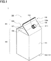
- Fig. 1 is a perspective view of the packaging container 3.
- the packaging container 3 includes a pour spout 1 and a container body 100 formed by folding a blank 110, which has been formed from a sheet material 200 (described later), into a box-like shape, and overlapping and sealing edges of the folded blank 110.
- the pour spout 1 includes a cap 2.
- the container body 100 includes a top section 101, body section 102, and bottom section 103. These sections respectively serve as a top part, side surface, and bottom part when the container 100 is erected.
- the top section 101 includes two roof panels 106 (106a, 106b), and a fold-back panel 107 and fold-inward panel 108, which are folded between the roof panels 106.
- the roof panel 106a has a circular pouring opening 114 formed therein.
- the pour spout 1 is mounted in the pouring opening 114.
- the top section 101 has a weakened section 105 with lower tensile strength.
- the weakened portion 105 is seen extending laterally in the left and right directions when the container body 100 is erected.
- Fig. 2A is a cross-sectional view of the pour spout 1
- Fig. 2B is a plan view from below of the pour spout 1.
- the pour spout 1 includes a cylindrical sidewall 11, partition wall 14 closing the interior of the sidewall 11, disk-like flange 15, and a plurality of recesses 17 formed in the bottom surface 20 of the flange 15.
- the pour spout 1 may be integrally formed with the container body 100, using low-density polyethylene (LDPE) or the like.
- LDPE low-density polyethylene
- the pour spout 1 is preferably made of a material having a flexural modulus of 100 MPa or more and 180 MPa or less, more preferably 120 MPa or more and 155 MPa or less.
- the sidewall 11 has an outer screw thread 12 on its outer peripheral surface 21.
- the outer screw thread 12 allows the cap 2, which has a screw thread on its inner peripheral surface, to be screwed from above.
- Below the outer screw thread 12 are three projections 19 which are formed as part of the outer peripheral surface 21 of the sidewall 11 so as to equally divide the circumference of the sidewall 11.
- Below the projections 19 is a disk-like flange 15 extending outwardly from the outer peripheral surface 21 of the sidewall 11.
- a surface of the flange 15 on the sidewall 11 side is joined to the container body 100 by ultrasonic welding.
- the container body 100 is sandwiched between the projection 19 and the flange 15.
- the bottom surface 20 of the flange 15, which is the opposite side of the sidewall 11, has a to-be-cut portion 22 where a plurality of recesses 17 separated by a plurality of ribs 18 are annularly arranged.
- the recess 17 is formed in the bottom surface 20 of the flange 15 and has a trapezoidal cross-section.
- the cross-section of the recess 17 may take various other shapes.
- the surfaces of the flange 15 may have projections of various shapes that serve as energy directors for increasing weldability by controlling the concentration of ultrasonic energy during ultrasonic welding.
- ribs 18 are disposed extending radially from the center of the sidewall 11 so as to equally divide the circumference of the sidewall 11.
- the top surface 23 of the rib 18 is formed flush with the bottom surface 20 of the flange 15.
- the top surface 23 of the rib 18 may be recessed from the bottom surface 20 of the flange 15.
- the partition wall 14 is formed near the lower end of the sidewall 11 to separate the interior of the sidewall 11 into a section on the upper end side and a section on the lower end side.
- the partition wall 14 is connected to the sidewall 11 by a half-cut portion 16, which is a thin outer peripheral portion formed annularly.
- the upper surface of the partition wall 14 is connected to a pull ring 13 via a pillar.
- a user raises the pull ring 13, which causes the partition wall 14 to break along the half-cut portion 16, allowing the user to pull out the broken partition wall 14 from the sidewall 11, which results in the sections on the upper and lower ends of the sidewall 11 communicating with each other.
- the flange 15 and the sidewall 11 are readily separated from each other along the to-be-cut portion 22, and the flange 15 has greater rigidity that prevents it from breaking due to ultrasonic vibrations.
- the number of the ribs 18 may be in the range from 24 or more to 48 or less, and the d1 and d2 may be in the range from 0.15 mm or more to 0.3 mm or less, especially from 0.2 mm or more to 0.25 mm or less.
- This configuration prevents breakage of the flange 15 due to ultrasonic vibrations during welding while allowing the flange 15 and the sidewall 11 to be readily separated from each other along the to-be-cut portion 22.
- d1 to d3 satisfy the relationship d2 ⁇ d1
- the to-be-cut portion 22 breaks in the order d2, d1 during separation, allowing the flange 15 and side wall 11 to be separated from each other more readily.
- d1 ⁇ d3 for example, a portion near the to-be-cut portion 22 bends or extends appropriately for easier separation.
- the rib 18 can take various shapes.
- Figs. 3A and 3B are plan views of a pour spout 1 according to a variation, where the shape of the rib 18 has been changed.
- the pour spout 1 ( Figs. 3A and 3B ) is viewed from the bottom surface 20 side.
- a plurality of ribs 181 of a pour spout ( Fig. 3A ), in the plan view of the flange 15, are formed extending from the inside to the outside of the flange 15 at a first predetermined angle less than 90° to the direction of rotation of the cap 2 being screwed (in the case of the pour spout 1, counterclockwise as viewed from the bottom surface 20 side).
- the first predetermined angle is, for example, 60°.
- a plurality of ribs 182 are formed on a pour spout ( Fig. 3B ).
- the ribs 182 extend from the inside to the outside of the flange 15 at a second predetermined angle less than 90° to a direction opposite the direction of rotation of the cap 2 being screwed.
- the second predetermined angle is, for example, 60°.
- triangular recesses 17 are arranged circumferentially. This honeycomb structure allows the flange 15 to be more rigid against loads applied from directions parallel to a plane including the flange 15.
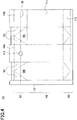
- Fig. 4 is a plan view of a blank 110, which is an example blank used to form a container body 100.
- the blank 110 includes roof panels 106a, 106b that constitute a top section 101, a fold-back panel 107 and fold-inward panel 108, four side panels 111 that constitute a body section 102, a bottom panel 112 that serves as a bottom section 103, and a to-be-sealed section 113 formed at an edge of the blank 110.
- the blank 110 is folded along a chain line ( Fig. 4 ), and the to-be-sealed section 113 is sealed to an edge on the opposite side thereof. The blank is thus formed into a box-like shape.
- the roof panels 106a, 106b, fold-back panel 107, and fold-inward panel 108 are formed with a linear weakened portion 105 laterally extending across substantially the entire width of the container body 100 in its erected state. A portion of the weakened portion 105 is interrupted by the pouring opening 114. Accordingly, a crease formed when the container body 100 is folded along the weakened portion 105 passes through the pouring opening 114.
- the weakened portion 105 may be formed in the longitudinal direction of the container body 100 as long as a portion thereof is interrupted by the pouring opening 114.
- Figs. 5A and 5B are schematic cross-sectional views of two example laminate structures of the sheet material 200 used to form the blank 110.
- the sheet material 200 includes a printed layer 208, thermoplastic resin layer 201, paper substrate layer 202, adhesive layer of resin 203, barrier layer 204, adhesive layer 205, and sealant layer 206 in that order from the outside of the packaging container 3.
- the sheet material 200 is formed with the weakened portion 105.
- the weakened portion 105 has groove-like cut portions 207a, 207b formed at least in the paper substrate layer 202 and the barrier layer 204 respectively.
- the cut portions each have a predetermined depth.
- the cut portion 207b of the barrier layer 204 is formed to overlap the cut portion 207a of the paper substrate layer 202 in plan view.
- the cut portion 207b is preferably formed extending within the barrier layer 204; however, the groove-like cut 207b may partially penetrate another layer because the penetration of small extent has only a slight influence on the barrier characteristics of the barrier layer 204.
- the cut portion 207a should at least be formed in the paper substrate layer 202.
- the cut portion 207a may also be formed in the stack of the thermoplastic resin layer 201 and printed layer 208 which are external to the paper substrate layer 202.
- the cut portion 207a may have any depth that allows the paper substrate layer 202 to provide sufficient strength of the packaging container 3.
- the cut portion 207a may be formed by half-cutting process or full-cutting process using a cutting die.
- the cut portions may be perforations to allow the packaging container 3 to have sufficient strength.
- the cut portion 207b may be formed by laser beam machining after lamination of the barrier layer 204. Before lamination of the barrier layer 204, the cut portion 207b may be formed by half-cutting process or full-cutting process using a cutting die, or by laser beam machining before lamination of the barrier layer 204.
- the cut portion 207b may also be perforations to allow the packaging container 3 to have sufficient strength.
- the thermoplastic resin layer 201 may be formed on the paper substrate layer 202 by extrusion lamination or the like, using low-density polyethylene resin (LDPE), linear low-density polyethylene resin (LLDPE), or the like.
- LDPE low-density polyethylene resin
- LLDPE linear low-density polyethylene resin
- the printed layer 208 provided outwardly of the thermoplastic resin layer 201 may show a pattern or product information.
- the printed layer 208 may be formed by gravure printing, offset printing, or the like using known ink.
- the adhesion of the thermoplastic resin layer 201 to the printed layer 208 may be increased by corona treatment or the like that facilitates the adhesion therebetween.
- An overcoat layer may be provided outwardly of the printed layer to increase wear resistance or degree of freedom in surface decoration.
- the paper substrate layer 202 may be formed of, for example, base paper for milk cartons.
- the basis weight and density of a container may be selected depending on the volume, design, or the like thereof.
- the adhesive layer of resin 203 is formed of polyolefin resin and provides adhesion between the paper substrate layer 202 and barrier layer 204.
- the adhesive layer of resin 203 may be formed of, for example, high-density polyethylene resin (HDPE), medium-density polyethylene resin (MDPE), LDPE, LLDPE, ethylene methacrylic acid copolymer (EMAA), ethylene acrylic acid copolymer (EAA), ionomer, polypropylene (PP).
- HDPE high-density polyethylene resin
- MDPE medium-density polyethylene resin
- LDPE low-density polyethylene resin
- LLDPE ethylene methacrylic acid copolymer
- EAA ethylene acrylic acid copolymer
- PP polypropylene
- a surface of the paper substrate layer 202 or barrier layer 204 may be subjected to corona treatment, ozonation, anchor coating, or the like.
- Another way to increase the adhesion is to use a dry lamination
- the barrier layer 204 may be formed of a deposition film including a substrate film 204a and a deposition layer 204b which is formed by depositing silica, alumina, metal such as aluminum, or the like.
- An alternative is to use a laminated film formed by laminating a metal foil 204c such as of aluminum to the substrate film 204a using dry lamination.
- the barrier layer 204 which is a deposition film, is formed of the substrate film 204a and the deposition film 204b disposed on a surface of the substrate film 204a, the surface to be on the inner side of the packaging container 3.
- the barrier layer 204 which is a laminated film, is formed of the substrate film 204a and the metal foil 204c disposed on a surface of the substrate film 204a, the surface to be on the outer side of the packaging container 3.
- the deposition layer 204b or metal foil 204c of the barrier layer 204 is laminated to face the adhesive layer of resin 203 so as to prevent the metal foil 204c from blocking a laser beam directed toward the substrate film 204a.
- the barrier layer 204 may be a polyethylene terephthalate film to which barrier coatings are applied, or a barrier film formed of barrier material such as EVOH.
- the substrate film 204a may be a resin film formed of polyethylene terephthalate (PET), nylon, polypropylene (PP), or the like.
- PET polyethylene terephthalate
- PP polypropylene
- a biaxially-oriented PET film is preferable because it has low expansion and shrinkage during deposition or lamination.
- the adhesive layer 205 may be a dry laminating adhesive or solventless laminating adhesive; instead, an extruded polyolefin resin may be used to provide adhesion.
- the sealant layer 206 may be formed of HDPE, MDPE, LDPE, LLDPE, or the like. There may be a layer containing polybutene. In particular, LLDPE is preferable. Preferably, the sealant layer 206 is a non-oriented film formed by T-die extrusion or blown film extrusion.
- the layer structure of the sheet material 200 and the weakened portion 105 are not limited to the above examples, and can be embodied in various forms.
- the pour spout 1 is ultrasonically welded to the container body 100 in the following way. First, the sidewall 11 of the pour spout 1 is inserted into the pouring opening 114 of the container body 100 from the inner surface side of the container body 100, and the surface of the flange 15 on the sidewall 11 side is placed against the inner surface of the roof panel 106a. As shown in Fig. 1 , the pour spout 1 is temporarily fastened to the container body 100, with a portion around the pouring opening 114 of the container body 100 sandwiched between the projection 19 and the flange 15.
- an anvil inserted inside the container body 100 and an ultrasonic horn (which are not shown) are placed on the roof panel 106a on the flange 15, and ultrasonic vibrations are produced to weld the roof panel 106 and flange 15.
- the vibrations cause the flange 15 to vibrate, this vibration is absorbed by the ribs 18, which prevents breakage of a portion around the recess 17.
- the rib 18 increases the rigidity of the flange 15. The increased rigidity allows the flange 15 to be welded to the roof panel 106 while the shape of the flange 15 is maintained. This prevents non-uniform welding.
- FIGs. 6A, 6B, and 6C each illustrate a process of separating the pour spout 1.
- Fig. 6A illustrates a process of flattening the packaging container 3.
- a user of the packaging container 3 presses the opposing two side panels 111, which extend down from the roof panel 106, in opposing directions, to flatten the body section 102.
- the other two side panels 111 in contact with the flattened side panels 111 are folded inwardly of the packaging container 3.
- Fig. 6B illustrates a process of folding the packaging container 3 along the weakened portion 105.
- the user folds the roof panel 106 along the weakened portion 105, as shown in Fig. 6B .
- Fig. 6C illustrates a process of separating the pour spout 1 from the packaging container 3.
- the portion around the recess 17 of the pour spout 1 allows the user to cut the pour spout 1 along the to-be-cut portion 22 with very little force, and to thus separate the pour spout 1 including the sidewall 11 from the packaging container 3.
- the present embodiment provides a pour spout that is sufficiently rigid to be prevented from breaking due to ultrasonic vibrations during welding and that is readily separated from a packaging container being broken down, and a packaging container with the pour spout.
- Fig. 7 is a perspective view of a packaging container 3.
- the packaging container 3 includes a pour spout 1 and a container body 100 formed by folding a blank 110, which has been formed from a sheet material (described later), into a box-like shape, and overlapping and sealing edges of the folded blank 110.
- the pour spout 1 includes a cap 2.
- the container body 100 includes a top section 10, body section 102, and bottom section 103. These sections respectively serve as a top part, side surface, and bottom part when the container body 100 is erected.
- the top section 101 includes two roof panels 106 (106a, 106b), and a fold-back panel 107 and fold-inward panel 108, which are folded between the roof panels 106.
- the roof panel 106a has a circular pouring opening 114 formed therein.
- the pour spout 1 is mounted in the pouring opening 114.
- Fig. 8 is a plan view of a blank 110, which is an example blank used to form the container body 100.
- the blank 110 includes roof panels 106a, 106b that constitute a top section 101, a fold-back panel 107 and fold-inward panel 108, four side panels 111 that constitute a body section 102, a bottom panel 112 that serves as a bottom section 103, and a to-be-sealed section 113 formed at an edge of the blank 110.
- the blank 110 is folded along a chain line ( Fig. 8 ), and the to-be-sealed section 113 is sealed to an edge on the opposite side thereof.
- the blank 110 is thus formed into a box-like shape.
- Around the center of the roof panel 106a is a pouring opening 114 in which the pour spout 1 is fixedly mounted.
- the sheet material may have a layer structure similar to that of the first embodiment. That is, the sheet material may include a printed layer, thermoplastic resin layer, paper substrate layer, adhesive layer of resin, barrier layer, adhesive layer, and sealant layer in that order from the outside of the packaging container 3.
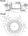
- Fig. 9A is a cross-sectional view of a pour spout 4, while Fig. 9B is a plan view from below of the pour spout 4.
- the pour spout 4 includes a cylindrical sidewall 31, partition wall 34 closing the interior of the sidewall 31, disk-like flange 35 extending from one end of the sidewall 31, and a plurality of recesses 37 formed in the bottom surface 40 of the flange 35.
- the pour spout 4 may be integrally formed with a container body 120, using LDPE, LLDPE, or the like.
- the sidewall 31 has an outer screw thread 32 on its outer peripheral surface 41.
- the outer screw thread 32 allows the cap 5, which has a screw thread on its inner peripheral surface, to be screwed from above.
- Below the outer screw thread 32 are three projections 39 which are formed as part of the outer peripheral surface 41 of the sidewall 31 so as to equally divide the circumference of the sidewall 31.
- Below the projections 39 is a disk-like flange 35 extending outwardly from the outer peripheral surface 41 of the sidewall 31.
- a surface of the flange 35 on the sidewall 31 side is joined to the container body 120 by ultrasonic welding.
- the container body 120 is sandwiched between the projection 39 and the flange 35.
- the bottom surface 40 of the flange 35 which is the opposite side of the sidewall 31, has a to-be-cut portion 42 where a plurality of recesses 37 separated by a plurality of ribs 38 are annularly arranged.
- the recess 37 includes a first wall surface 44 and a second wall surface 45, which are formed concentric with the sidewall 31.
- the second wall surface 45 is outward of the first wall surface 44.
- the recess 37 further includes a top surface 46 connected to the first and second wall surfaces 44 and 45.
- the top surface 46 is connected to the first and second wall surfaces 44 and 45 at a predetermined angle.
- the bottom surface 40 is connected to the first and second wall surfaces 44 and 45 via a rounded section 47.
- a section with an edge, for example, is formed between the first and second wall surfaces 44 and 45 instead of the rounded section 47, the recess 37 easily buckles in the left and right directions in Fig. 9A due to ultrasonic vibrations delivered to the recess 37 during ultrasonic welding.
- a portion of the flange 35 around the recess 37 may deform to have the material squeezed out. This results in the flange 35 having an excess portion, for example, which may separate from the flange 35 to become foreign material.
- the surfaces of the flange 35 may have projections of various shapes that serve as an energy director for increasing weldability by controlling the concentration of ultrasonic energy during ultrasonic welding.
- fifteen ribs 38 are disposed extending radially from the center of the sidewall 31 so as to equally divide the circumference of the sidewall 31.
- the bottom surface 43 of the rib 38 is formed flush with the bottom surface 20 of the flange 35; however, the bottom surface 43 of the rib 38 may be recessed from the bottom surface 40 of the flange 35.
- the partition wall 34 is formed near the lower end of the sidewall 31 to separate the interior of the sidewall 31 into a section on the upper end side and a section on the lower end side.
- the partition wall 34 is connected to the sidewall 31 by a half-cut portion 36, which is a thin outer peripheral portion formed annularly.
- the upper surface of the partition wall 34 is connected to a pull ring 33 via a pillar.
- a user raises the pull ring 33, which causes the partition wall 34 to break along the half-cut portion 36, allowing the user to pull out the broken partition wall 34 from the sidewall 31, which results in the sections on the upper and lower ends of the sidewall 31 communicating with each other.
- the flange 35 and the sidewall 31 are readily separated from each other along the to-be-cut portion 42, and the flange 35 has greater rigidity that prevents it from breaking due to ultrasonic vibrations.
- the number of the ribs 38 may be adjusted depending on the required tensile strength. Preferably, an odd number of the ribs 38 are provided to equally divide the circumference for the following reason. As described later, the user folds the packaging container 6 along a line substantially passing through the diameter of the pour spout 4 when separating the pour spout 4 from the container body 120. The odd number of ribs 38, which each have greater rigidity, will not be located at ends of the pour spout 4's diameter simultaneously, so that separation of the pour spout 1 is not difficult.
- d7 and d9 are 0.15 mm or more and 0.45 mm or less.
- d7 and d9 of 0.15 mm or more incomplete filling is prevented during integral molding using LDPE, LLDPE, or the like.
- d7 and d9 of 0.45 mm or less a portion around the recess 37 is prevented from breaking due to ultrasonic vibrations while the flange 35 and the sidewall 31 are readily separated from each other along the to-be-cut portion 42.
- d7 and d9 set to approximately the same value, an approximately equal load is required to break the recesses 37 and ribs 38. This allows the pour spout 4 to break and separate smoothly with a constant force.
- d7 and d9 are 0.2 mm or more and 0.3 mm or less. With d7 and d9 of 0.2 mm or more, poor filling during integral molding is less likely to occur; d7 and d9 of 0.3 mm or less allow easy cutting.
- d8 is 0.3 mm or more and 1.0 mm or less.
- a mold for integral molding of the pour spout 4 has sufficient strength and is thus durable.
- the to-be-cut portion 42 has sufficient strength to prevent deformation and thus improper feeding of the pour spout 4 during use of a capping machine or a filling machine.
- d8 is 0.5 mm or more and 0.8 mm or less.
- a molding die has sufficient strength; d8 of 0.8 mm or less allows the to-be-cut portion 42 to have sufficient strength.
- d4 is an outer diameter of the sidewall 31 at a portion facing the inner peripheral surface of the pouring opening 134
- d5 is an inner diameter of the pouring opening 134
- d6 is an outer diameter of the sidewall 31 at a portion connecting the first wall surface 44 to the top surface 46.
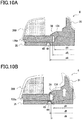
- Fig. 10A is an enlarged cross-sectional view of the flange 35 and its surroundings of the pour spout 4, illustrating ultrasonic welding of the pour spout 4 to the container body 120.
- Fig. 10A illustrates welding of the packaging container 6, while Fig. 10B illustrates, for comparison, welding of a pour spout that does not satisfy Formula 1.
- the pour spout 1 is ultrasonically welded to the container body 100 in the following way.
- the sidewall 31 of the pour spout 4 is inserted into the pouring opening 134 of the container body 120 from the inner surface side of the container body 120, and the surface of the flange 35 on the sidewall 31 side is placed against the inner surface of the roof panel 126a.
- an anvil (not shown) is inserted inside the container body 120, and is placed on the under surface of the roof panel 126a.
- An ultrasonic horn 209 is placed on the upper surface of the roof panel 126a on the flange 35, and ultrasonic vibrations are produced to weld the roof panel 126 and flange 15.
- the pouring opening 134 will not have an inner diameter D2 on the outside of an outer diameter D3 of the first wall surface 44 at any mounting location.
- the sheet material of the container body 120 covers the top surface 46 of the recess 37 to serve as a bracer, allowing the pour spout 4 to be properly welded without deformation due to ultrasonic vibrations during welding. Further, during distribution, or storage, for example, the recess 37 is protected by the sheet material, providing for a packaging container 3 which will not suffer from unintended breakage.
- Formula 1 is derived in the following way.
- the clearance between the inner peripheral surface of the pouring opening 134 and a portion of the sidewall 31 facing the inner peripheral surface has a value of 0 or more and (d5 - d4) or less, depending on the amount of misalignment between the central axis of the pour spout 4 and the central axis of the pouring opening 134.
- the pour spout of the present invention is not limited to the above embodiments, and various modifications of, for example, the cross-section of the recess 37 are possible.
- FIGs. 11A and 11B each illustrate a process involved in separating the pour spout 4.
- Fig. 11A illustrates a process of flattening the packaging container 6.
- a user of the packaging container 6 presses the opposing two side panels 131, which extend down from the roof panel 126, in opposing directions, to flatten the body section 122.
- the other two side panels 131 in contact with the flattened side panels 131 are folded into the packaging container 6.
- Fig. 11B illustrates a process of folding the packaging container 6.
- the user folds the roof panel 126, side surface 131, and bottom panel 132 in the left and right directions as shown on the left portion of Fig. 11B .
- Fig. 11B illustrates a process of separating the pour spout 4 from the packaging container 6.
- the portion around the recess 37 of the pour spout 4 allows the user to cut the pour spout 4 along the to-be-cut portion 42 with little effort, and to thus separate the pour spout 4 including the sidewall 31 from the packaging container 6.
- the packaging container 6 may be provided with a weakened line as appropriate, and folded along it. Further, before or after separation of the pour spout, there may be a process of separating the packaging container 6 into two or more parts.
- a pour spout 87 of the present embodiment includes a cylindrical sidewall 82 and a disk-like flange 871 extending outwardly from near the lower end of the sidewall.
- the sidewall 82 has on its outer side a male thread 821 onto which a cap 88 is screwed, and on its inner side a closure plate 831 of a pull tab 83.
- the closure plate 831 is connected with the inner side of the sidewall via a weakened line 830, and has a pull ring 8311 connected to the closure plate 831 via a pillar 8312 on the spout side of the closure plate 831.
- a pedestal 84 At the lower end of the sidewall 82 is a pedestal 84.
- the flange 871 is welded into an opening 86 of the paper container 1, extending horizontally from the lower end of the pedestal 84 to the outer side.
- the flange 871 has a plurality of concentrically arranged annular recesses 811 in its bottom surface opposite the sidewall.
- An outer annular recess 8111 has an arched top surface with a large radius of curvature R when viewed in transverse cross-section. With this configuration, the outer annular recess 8111 is less likely to break due to vibrations during ultrasonic welding.
- the outer annular recess absorbs ultrasonic vibrations produced during welding so that they are not delivered to an inner annular recess. Thus, the outer annular recess prevents breakage of the inner annular recess, and absorbs excess portions of the flange which are melted during welding to the container.
- An inner annular recess 8112 has a top surface with a corner having a radius of curvature of 0 or less than the above radius of curvature R when viewed in transverse cross-section. Further, the inner wall of the inner annular recess 8112 is formed near a standing wall 841 of the pedestal 84. Preferably, the inner wall of the inner annular recess 8112 is formed near the position directly under the standing wall 841, or formed inwardly of the standing wall 841. A horn for ultrasonic welding is configured so that it is not positioned directly above the inner annular recess 8112 when the pour spout 87 is welded to a container 81.
- the horn delivering ultrasonic vibrations to weld the pour spout 87 to the container 81 is basically designed to be in contact with a portion outward of the outer annular recess 8111 or the inner outer recess 8112.
- the lower portion of Fig. 12 is a bottom view of the pour spout 87.
- the closure plate 831 of the pull tab is located at the center, and is connected with the sidewall by the weakened line 830.
- the pedestal is provided with a thinned portion 842.
- the thinned portion is a recess separated by ribs; however, the ribs may be omitted. Alternatively, the thinned portion may be just a step. Outside the thinned portion 842 of the pedestal, the inner annular recess 8112 and the outer annular recess 8111 are concentrically provided. A part of the bottom view of the pour spout 87 is enlarged for better understanding.
- the outer annular recess 8111 and the inner annular recess 8112 are provided with a plurality of ribs.
- An outer annular rib 81110 of the outer annular recess 8111 and an inner annular rib 81120 of the inner annular recess 8112, which are adjacent to each other, are offset from each other. That is, these ribs are formed at the positions in different directions as viewed from the center of the flange. Accordingly, the outer annular rib 81110 and the inner annular rib 81120 of the annular recesses are preferably equal in number.
- an outer annular rib thickness d11 of the outer annular recess is set greater than an inner annular rib thickness d10 of the inner annular recess. This is done to increase the strength of the flange of the outer annular recess and to thus prevent the outer annular recess from being easily broken due to ultrasonic vibrations.
- a flange thickness d12 at the outer annular recess and a flange thickness d13 at the inner annular recess are set less than the inner annular rib thickness d10 of the inner annular recess, and less than a ring width d14 of the inner annular recess.
- the flange thicknesses d12 and d13 of the annular recesses are each 0.2 mm or more and 0.3 mm or less. This is because a flange thickness of less than 0.2 mm may result in formation of cracks during ultrasonic welding of the flange to the container body, and a flange thickness of more than 0.3 mm makes cutting difficult.
- a preferable thickness is 0.23 mm or more and 0.3 mm or less.
- An outer annular recess width d15 and an inner annular recess width d14 are 0.3 mm or more, preferably 0.5 mm or more. This is because a width of less than 0.3 mm may result in an injection mold having low strength and thus low durability.
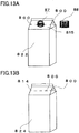
- Figs. 13A and 13B show a packaging container 81 with the pour spout 87.
- Fig. 13A is a perspective view of the packaging container 81 as viewed from its front surface 822 connected to an upper inclined surface 815 to which the pour spout is welded.
- Fig. 13B is a perspective view of the packaging container 81 as viewed from its rear surface 824.
- the upper inclined surface 815, to which the pour spout is welded, and an upper rear inclined surface 814 are provided with a horizontal score 800 passing through the center of the opening 86 to which the pour spout 87 is welded.
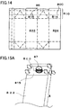
- Fig. 14 is a developed view of a blank used to form the container 81 shown in Figs. 13A and 13B . All the upper surfaces constituting an upper portion 810 are provided with the score 800 passing through the center of the opening 86.
- Figs. 15A and 15B each illustrate a process of separating the pour spout 87 after discharging the contents of the paper container welded with the pour spout 87 of the present invention shown in Figs. 13A, 13B and 14.
- Fig. 15A illustrates a process of flattening the paper container by inwardly folding the left and right side surfaces of the container 81.
- a force is applied to the flattened container so that it is folded along the score 800 formed of ruled lines. With the application of force, as shown in Fig.
- the flattened container is folded along the score 800, causing the flange to break at the inner annular recess 8112 without the sidewall 82 and pedestal 84 of the pour spout 87 being folded.
- Figs. 16A and 16B show an example paper container welded with the pour spout 87 of the present invention, with a score 800 passing through the container in its longitudinal direction, illustrating a process of separating the pour spout 87 from the container whose contents have been discharged.
- Fig. 16A illustrates a process of flattening the paper container by inwardly folding the left and right side surfaces of the paper container 81.
- a force is applied to the flattened container so that it is folded along the score 800 formed of ruled lines. With the application of force, as shown in Fig.
- the flattened container is longitudinally folded along the score 800, causing the flange to break at the inner annular recess 8112 without the sidewall 82 and pedestal 84 of the pour spout 87 being folded.
- the longitudinal score 800 is positioned so that, with the left and right side surfaces of the paper container 81 folded and collapsed, the longitudinal score 800 allows the container to be easily folded. Accordingly, the position of the longitudinal score 800 is advantageous for folding the flattened container with very little force. With the longitudinal folding of the flattened container, half of the flange separated by the score 800 breaks. Since the remaining inner annular recess 8112 of the flange is also thinned, the breakage of half the flange allows the pour spout to be broken at a portion between the pedestal and the remaining flange and separated from the container.
- Figs. 17A and 17B show examples in which the present invention is applied to a flat-top paper container instead of to a gable-top paper container.
- the flat-top paper container includes a top surface folded in half and sealed thereto.
- the flat-top paper container requires its top plate to be folded for separation of the pour spout 87 from the top portion, the pour spout can be used. In this case, since the top plate has high strength, the pour spout can be broken by simply pushing down the sidewall 82 thereof without separation of the top portion.
- Fig. 18 is an example pour spout where a plurality of annular recesses having a plurality of ribs are concentrically provided at a to-be-welded region of the upper surface of the flange on the sidewall side.
- This pour spout can be subjected to welding even if it has a soft flange, and is provided with an annular recess 85 in a surface to be welded, with the annular recess 85 separated by the plurality of ribs.
- the annular recesses include ribs 853 formed such that ribs of an inner side annular recess 852 are disposed adjacent to and offset from ribs of an outer side annular recess 851.
- these ribs are formed at the positions in different directions as viewed from the center of the flange.
- the rib 853 of the annular recess prevents a horn which delivers ultrasonic waves from falling into the recess.
- the rib and the recess allow ultrasonic vibrations to be uniformly delivered to the to-be-welded surface.
- the flange of the pour spout 87 can be uniformly welded to the container 81 with almost no fine height adjustment which is usually required for the welding.
- This welding method enables stable welding without a large decrease in weldability even under the condition that the pressure, amplitude, and work of welding are reduced.
- the welded portion of the pour spout is formed without an energy director, which is a protrusion.
- Fig. 19 shows a pour spout using a combination of the features of the pour spouts ( Figs. 12 and 18 ).
- a cross-sectional view of the pour spout is shown; on the middle portion, a plan view of the pour spout as seen from a bottom surface side (inner side of a container); and on the bottom portion, a plan view of the pour spout as seen from the outside.
- a container shown in Fig. 19 has a soft flange with a plurality of inner and outer annular recesses. This structure improves weldability and ease of breakdown.
- the requirements for the material of the pour spout 87 is that it have good weldability to a sealant layer used in a container body, have high resistance to stress cracking so as to be less affected by the contents, and have appropriate rigidity that allows easy capping.
- the pour spout 87 is preferably formed of a material having a density of 0.900g/cm 3 or more to 0.950g/cm 3 or less, such as low-density polyethylene, linear low-density polyethylene, or the like.
- Examples of the material of the pour spout 87 include medium-density polyethylene, mixed resin of low- and high-density polyethylene, ionomer resin, and ethylene-vinyl acetate copolymer added thereto and mixed.
- linear low-density polyethylene is preferable.
- resins are subjected to a test for environmental stress cracking. For this test, pour spouts are molded with various resins, and are each welded to a paper container having the contents with which such containers are intended to be filled. Then the test is conducted, and appropriate material is selected from such resins.
- a paper container of the present invention has a substrate formed primarily of paper.
- the substrate is made of a cardboard having a basic weight of 200g/m 2 to 800g/m 2 .
- a coated manila board, coated board, ivory board, or the like that is white on one side may be used.
- a laminated sheet is used having a sealant layer on its rear surface formed of a thermoplastic film with good sealability, such as a thin polyethylene film, ethylene-vinyl acetate copolymer film, or polypropylene film, with the thickness of such films set to 15 ⁇ m to 100 ⁇ m.
- the sealant layer is preferably formed of linear low-density polyethylene having a density of 0.925g/cm 3 or less, a melt flow rate of 4g/10min or more, and a thickness of 30 to 100 ⁇ m.
- a sealant layer is preferably disposed on the front surface side as well.
- Examples of the layer structure may include the following from the outside: polyethylene, paper, and polyethylene; polyethylene, paper, polyethylene, inorganic oxide deposited polyethylene terephthalate, and polyethylene; polyethylene, paper, polyethylene, aluminum deposited polyethylene terephthalate, and polyethylene; polyethylene, paper, polyethylene, aluminum foil, polyethylene terephthalate, and polyethylene; polyethylene, paper, polyethylene, saponified ethylene-vinyl acetate copolymer, and polyethylene; and polyethylene, paper, polyethylene, adhesive resin, polyamide, adhesive resin, and polyethylene.
- These structures can be easily made by dry laminating machine, extrusion laminating machine, or the like.
- the pour spout according to the present embodiment has good ultrasonic weldability, which enables rapid welding and thus high productivity. Further, the pour spout can be removed for disposal without using cutting tools such as a knife, thus making it safe to use and reducing the burden on a person disposing of it. With the ease of breaking it down, more people are expected to remove the pour spout when disposing of it. Further, since a mold for the present invention is made by adding only an annular recess to a pour spout mold, the mold can be produced in high volume, and the existing production facilities can be used. Thus the present invention offers great advantages.
- Fig. 21 schematically illustrates an example of a pour spout and a cap according to the present embodiment.
- Fig. 22 schematically illustrates a packaging container according to the present embodiment.
- Fig. 23 schematically illustrates in cross-section an example flange of the pour spout according to the present embodiment.
- Fig. 24 is a partial enlarged view of the example flange ( Fig. 23 ).
- a pour spout 900 with a cap includes a pour spout 91 and a cap 92.
- the pour spout 91 includes a sidewall 911 serving as a pouring passage, and a flange 912 extending outward from a lower end of the sidewall 911.
- the spout assembly 900 is mounted to a container body from inside thereof, so that the sidewall 911, the cap 92, and the like are located outside thereof, with the upper surface of the flange 912 sealed to the inner surface of the container body 902.
- the sealing is achieved by ultrasonic sealing.
- the mounting procedure will be described below. First, a trunk portion and a side portion are formed. Then the spout assembly 900 is put into the container body from its upper end opening, and the sidewall 911 of the spout assembly 900, which is fitted with the cap 2, is inserted into a spout assembly-mount opening.
- the flange 912 is brought into contact with the perimeter area of the spout-plug-mount opening on the inside of the container body.
- the flange 912 is then pressed against the perimeter area from inside by a sealing-receiving anvil of an ultrasonic sealing machine, followed by ultrasonically vibrating the container body from outside using an ultrasonic sealing horn to thereby achieve ultrasonic sealing.
- Fig. 23 shows in cross-section of the flange 912 of the spout assembly 900 according to the present embodiment, taken along the center line perpendicular to the left and right direction in the right half of the flange 912.
- the flange 912 has a lower surface provided with an asperity, and a flat upper surface.
- the asperity is formed of a thin annular recessed portion 913 surrounding the sidewall 911, and a plurality of annular projections 914 provided apart from the annular recessed portion 13.
- the annular projections 914 are brought into contact with the sealing-receiving anvil, with the rest of the flange not being in contact therewith. Also, since the annular projections 914 each have a greater thickness, the vibration energy of the ultrasonic waves is concentrated on the annular projections 914 for melting and sealing. Consequently, melting and sealing are unlikely to occur between the annular projections 914. In addition, no sealing occurs at the annular recessed portion 913.
- the thin annular recessed portion 913 remains unchanged even after the flange 912 has been mounted to the container body by ultrasonic sealing.
- the sidewall 11 can be detached from the container body 902 by breaking the annular recessed portion 913.
- the container body 902 can be collected for paper recycling, contributing to enhancing ecology.
- d16 ⁇ d17 ⁇ d18 is satisfied, where d16 is the width of the annular recessed portion 913, d17 is a distance from the annular recessed portion 913 to the nearest annular projection 914 that is immediately outside the annular recessed portion 913, and d18 is the width of each annular projection 914.
- the width d18 of the annular projection 914 is preferably small.
- the ultrasonic vibration energy is likely to be concentrated on the annular projections 914 to easily melt the projections 914.
- the energy is unlikely to be transferred to the annular recessed portion 13, eliminating the occurrence of leakage of the contents due to otherwise insufficient sealing.
- d19 ⁇ d20 ⁇ d21 is satisfied, where d19 is the thickness of the annular recessed portion 913, d20 is a recess depth of the annular recessed portion 913, and d21 is a height of the annular projections 914 outside the annular recessed portion 913.
- d21 is a height of the annular projections 914 outside the annular recessed portion 913.
- the thickness d19 is preferably 0.20 mm or more, and more preferably 0.25 mm or more. If the thickness is less than this, the flange 912 may come off when the cap is opened for example.
- the thickness d19 is preferably greater than the thickness of the thin and easily-broken portion provided along the perimeter of the inner lid. Otherwise, the annular recessed portion 913 may be broken when the inner lid is opened by pulling the pull ring.
- the pour spout 91 and the cap 92 of the spout assembly 900 can be produced by injection molding or the like.
- the pour spout 91 which is for sealing to the inner surface of the container body, is formed by molding a thermoplastic resin that is sealable with a thermoplastic resin, such as polyethylene, that forms the inner surface of the container body.
- the cap 92 preferably has flexibility sufficient to cap the pour spout 91.
- a thermoplastic resin such as polyethylene or polypropylene, is used as a material for the cap 92.
- the container body 902 to which the spout assembly 900 is mounted is made of a laminate material that is a paper board, such as milk carton base paper, with a thermoplastic resin provided to both the inner and outer surfaces of the paper board. If the laminate material is required to have gas barrier properties, a barrier layer is provided between the paper board and the thermoplastic resin on the inner surface thereof.
- An inorganic oxide deposited film is preferably used as the barrier layer.
- Silica, alumina, or the like is preferably used as the inorganic oxide to be deposited.
- materials that can be used for the base of the inorganic oxide deposited film include resin films such as of polyethylene terephthalate, nylon, or polypropylene.
- a biaxially-oriented resin film is preferably used because such a film is less stretchable during bonding, deposition, or the like.
- an aluminum foil may be used as the barrier layer.
- the shape of the packaging container in Fig. 22 is of a gable top type (gable roof type). However, the shape is not limited to this.
- the packaging container may be of a brick type with a flat top, or may be of a type with a front-inclined and rear-flat top. Any packaging container may be used as long as it is of a type where a spout assembly is attached to the opening of the container body thereof.
- the spout assembly 900 of the present embodiment is provided with the annular projections 914 on the flange 912, the ultrasonic sealing conditions when the spout assembly 900 is mounted to the container body 902 can be eased as described above.
- the conventional spout assemblies with a flange having flat front and back surfaces have been sealed under standard sealing conditions. Compared with this, the spout assembly 900 of the present embodiment can allow the sealing conditions to be eased as shown in Table 1.
- the thin annular recessed portion 913 remained unchanged.
- the annular recessed portion 913 was broken, and the cap 92 and the sidewall 911 of the pour spout 91 were removed.
- the pour spout of the present embodiment which is provided with the annular projections, enables uniform sealing and is reliably sealed to the container body.
- no pin hole is formed in the annular recessed portion due to heat, which prevents leakage of the contents.
- the pour spout can be easily detached from the container body by breaking the annular recessed portion, and thus is suitable for paper recycling.
- the present invention is not limited to the embodiments described above, and may be implemented with appropriate modifications.
- the pour spout of the first embodiment may be combined with the container body of other embodiments.
- Example 1 the pour spout 1 ( Figs. 2A and 2B ) was made, with the ribs 18 being formed radially extending from the center of the sidewall 11.
- Example 2 the pour spout 1 according to Variation 1 was made.
- the ribs 181 were formed extending outward from the inside of the flange 15 at an angle of 60° relative to the direction of rotation of the cap 2 being screwed.
- Example 1 Example 2 Comparative Example Sealing energy [J] 105 110 125 Amplitude [%] 70 70 75 Air pressure [Kpa] 300 300 300 Sealing time [Sec] 0.195 0.200 0.200
- a laminate sheet was made with a layer structure including the following from the outside: polyethylene (20 ⁇ m in thickness) / paper (400 g/m 2 in basis weight) / polyethylene (20 ⁇ m in thickness) / silicon oxide deposit (60 ⁇ m in deposition thickness) / polyethylene terephthalate (12 ⁇ m in thickness) / polyethylene (20 ⁇ m in thickness) / linear low-density polyethylene (40 ⁇ m in thickness).
- the laminate sheet was cut to size, followed by creasing and folding to obtain a paper container for 1-liter liquid with a 70 mm-square bottom.
- the pour spout 87 with a shape shown in Fig. 12 was formed by injecting a low-density polyethylene resin.
- the pour spout was sealed to the paper container by using an ultrasonic sealing machine with a frequency of 20 KHz, under the conditions shown in Table 1.
- Example 3 The same laminate sheet as that of Example 3 was made, and, based on the developed view shown in Fig. 14 , cut to size, followed by creasing and folding in the same manner as in Example 1, to thereby obtain a paper container for 1-liter liquid with a 70 mm-square bottom.
- the same pour spout 87 as in Example 3 was used.
- the pour spout was sealed to the paper container by using an ultrasonic sealing machine with a frequency of 20 KHz, under the conditions shown in Table 1.
- Example 3 The same laminate sheet as that of Example 3 was made, and, based on the developed view shown in Fig. 14 , cut to size, followed by creasing and folding in the same manner as in Example 3, to thereby obtain a paper container for 1-liter liquid with a 70 mm-square bottom.
- the pout spout 87 with only one annular recessed portion as shown in Fig. 20 was made by injection molding the same low-density polyethylene resin as in Example 3.
- the pour spout was sealed to the paper container by using an ultrasonic sealing machine with a frequency of 20 KHz, under the conditions shown in Table 1.
- the mark ++ indicates that deformation occurred neither in the entirety of the pour spout, nor in the flange at the annular recessed portion.
- the mark - indicates that deformation occurred both in the entirety of the pour spout and in the flange at the annular recessed portion.
- the mark + indicates that deformation occurred either in the entirety of the pour spout, or in the flange at the annular recessed portion.
- Three paper containers with a pour spout for each Example that is, a total of nine paper containers with a pour spout, were tested by each of three ordinary housewives to confirm whether the pour spout was broken in the annular recessed potion of the flange and easily detached from the paper container by folding the paper container along the score passing through the center of the pour spout.
- the mark ++ indicates successful breakdown of eight or more paper containers
- the mark + indicates successful breakdown of five or more and seven or less paper containers
- the mark - indicates successful breakdown of four or less paper containers, all within 15 seconds.
- the paper containers were made for each example and 1-liter of water was filled in each of the paper containers.
- the paper containers were placed upside down, and left standing for 7 days to check for the occurrence of leakage.
- the mark +++ indicates that none of five paper containers suffered leakage for 7 days.
- the mark ++ indicates that four paper containers suffered no leakage for 7 days, and one suffered no leakage for 5 or more days.
- the mark + indicates that three paper containers suffered no leakage for 7 days, and two suffered no leakage for 3 or more days.
- the mark - indicates that more leakage was caused than in the above.
- Example 3 neither pour spout deformation nor leakage was found, and there was no problem in adhesion. Further, in terms of ease of breakdown, the pour spouts of the nine paper containers were reliably detached.
- Example 4 neither pour spout deformation nor leakage was found. Only one paper container suffered little leakage on the 7th day. Further, in terms of ease of breakdown, the pour spouts of the nine paper containers were detached.
- Example 5 the pour spout was deformed to cause strain in the upper plate of the paper container to which the pour spout was mounted. Although there was no leakage, non-uniformity was found in the adhesion test, that is, a problem was found in adhesion. In the breakdown test, the pour spouts were not easily broken at all. Cutters, such as scissors or a knife, were required to be used for detachment.
- the pour spouts of Examples 3 and 4 are considered to enhance adhesion to the paper container more than in Examples 1 and 2, owing to the sealing at high temperature and large amplitude.
- the pour spout of Example 5 was highly evaluated in all evaluation items, under sealing conditions similar to those of Example 1.
- the present invention is useful for a paper packaging container or the like for containing liquid or the like.
Landscapes
- Engineering & Computer Science (AREA)
- Mechanical Engineering (AREA)
- Cartons (AREA)
- Packages (AREA)
- Closures For Containers (AREA)
Abstract
Description
- The present invention relates to a pour spout and a packaging container with the pour spout.
- Packaging containers are known having a container body with a pour spout such as that shown in
Fig. 25 . The container body is formed as follows: a sheet material is formed by laminating a barrier layer (such as an aluminum foil, aluminum deposited film, or inorganic deposited oxide film) between a paper substrate layer and a sealant layer of thermoplastic resin (see PTL 1), the sheet material is folded into a box-like shape, edges of the sheet material are overlapped, followed by sealing. Such packaging containers are widely used as containers of, for example, fruit drinks, juice, tea, coffee, milk beverages, liquid foods, such as soups, and alcoholic drinks, such as sake and shochu. - Such packaging containers can take various forms. One such packaging container has a gable roof panel formed with a cap and a pour spout which are made of, for example, polyethylene. The cap and pour spout allow liquids inside the container to be poured out. For environmental preservation, a used empty container should desirably be sorted and collected, and a pour spout welded to a container body made of a paper sheet material should desirably be separated from it for disposal to reduce the amount of waste. The container and pour spout can be separated by opening the top seal and cutting a sheet material around the pour spout using scissors or the like. However, such packaging containers are usually hard to break down because the top seal is firmly welded thereto, and cutting such packaging containers with scissors or the like is time-consuming. For these reasons, such containers are often discarded without separation of a pour spout.
- Against this background, liquid paper containers have been developed having a pour spout readily separable therefrom.
PTL 2 discloses a paper package, which is a paper container made with scores and a pour spout having an annular thin-walled portion formed on the inner upper surface of an annulus (flange). The paper package is folded along the scores, which allows the annular thin-walled portion to break, resulting in a cylindrical section of the pour spout separating from the paper container. -
PTL 3 discloses a spout assembly formed of a pour spout and a cap. The spout assembly has a breakable thin-walled portion formed on the inner upper surface of a flange extending outwardly from the lower end of the outer surface of a side wall that serves as a pouring passage of the pour spout. The portion of the upper surface extending radially outwardly from the thin-walled portion is bonded to a periphery of an opening of a liquid paper container. When the thin-walled portion breaks, the portion of the flange extending outwardly from the thin-walled portion is completely separated from the side wall. -
- PTL 1:
JP 2003-335362 A - PTL 2:
JP 5469421 B - PTL 3:
JP 2011-73748 A - However, a pour spout with a thin-walled portion (as described in
PTL 2 and 3) has a less rigid flange. Because of the reduced rigidity, when the pour spout is welded to a paper container by ultrasonic welding, the thin-walled portion and its surroundings may deform due to ultrasonic vibrations, or the cylindrical section may rise from the flange, or pinholes may form in the thin-walled portion, or the thin-walled portion may break, or the thin-walled portion may not be broken after welding. In these cases, the pour spout may be improperly welded to the paper container. - With such a pour spout, stable welding has not been achieved even if the shape of a horn of an ultrasonic sealing machine or the intensity of ultrasound is adjusted. For uniform sealing, the intensity of an ultrasonic energy is conventionally high. This approach, however, may deform a flange of the spout assembly, in which case the contents of the paper container are more likely to leak.
- The present invention has been made in view of these problems. An object of the present invention is to provide a pour spout that is sufficiently rigid to be prevented from breaking due to ultrasonic vibrations during welding and that is readily separated from a packaging container being broken down, and a packaging container with the pour spout.
- To overcome the problems, an aspect of the present invention provides a pour spout including a cylindrical sidewall and a disk-like flange extending outwardly from one end of the sidewall. The flange has a to-be-cut portion formed with a plurality of recesses that are annularly arranged and separated by a plurality of ribs.
- Another aspect of the present invention provides a pour spout including a cylindrical sidewall and a disk-like flange extending outwardly from one end of the sidewall. On the flange's bottom surface opposite the sidewall, the flange has an annular recess and at least one annular projection that is outwardly spaced from the annular recess a predetermined distance.
- Another aspect of the present invention provides a packaging container that is formed by folding a sheet material into a box-like shape, and that includes a container body with a pouring opening and the above-described pour spout mounted in the pouring opening, with its flange welded to the sheet material.
- The present invention provides a pour spout that is sufficiently rigid to be prevented from breaking due to ultrasonic vibrations during welding and that is readily separated from a packaging container being broken down, and a packaging container with the pour spout.
-
-
Fig. 1 is a perspective view of a packaging container according to a first embodiment of the present invention. -
Fig. 2A is a cross-sectional view of a pour spout according to the first embodiment of the present invention. -
Fig. 2B is a plan view of the pour spout according to the first embodiment of the present invention. -
Fig. 3A is a plan view of a pour spout according to a variation on the first embodiment of the present invention. -
Fig. 3B is a plan view of a pour spout according to a variation on the first embodiment of the present invention. -
Fig. 4 is a plan view of a blank according to the first embodiment of the present invention. -
Fig. 5A is a schematic cross-sectional view of a laminate structure of a sheet material according to the first embodiment of the present invention. -
Fig. 5B is a schematic cross-sectional view of a laminate structure of a sheet material according to the first embodiment of the present invention. -
Fig. 6A illustrates a method of separating the pour spout according to the first embodiment of the present invention. -
Fig. 6B illustrates the method of separating the pour spout according to the first embodiment of the present invention. -
Fig. 6C illustrates the method of separating the pour spout according to the first embodiment of the present invention. -
Fig. 7 is a perspective view of a packaging container according to a second embodiment of the present invention. -
Fig. 8 is a plan view of a blank used to form a packaging container according to the second embodiment of the present invention. -
Fig. 9A is a cross-sectional view of a pour spout for use in the packaging container according to the second embodiment of the present invention. -
Fig. 9B is a plan view of the pour spout for use in the packaging container according to the second embodiment of the present invention. -
Fig. 10A is an enlarged cross-sectional view of a flange and its surroundings of the pour spout according to the second embodiment of the present invention, illustrating ultrasonic welding of the pour spout to a container body. -
Fig. 10B is an enlarged cross-sectional view of a flange and its surroundings of a pour spout according to a comparative example of the second embodiment of the present invention, illustrating ultrasonic welding of the pour spout to a container body. -
Fig. 11A illustrates a method of separating the pour spout according to the second embodiment of the present invention. -
Fig. 11B illustrates the method of separating the pour spout according to the second embodiment of the present invention. -
Fig. 12 is a cross-sectional view and a bottom view of a pour spout according to a third embodiment of the present invention. -
Fig. 13A is a perspective view of a container according to the third embodiment of the present invention. -
Fig. 13B is a perspective view of the container according to the third embodiment of the present invention. -
Fig. 14 is a developed view of a container body according to the third embodiment of the present invention. -
Fig. 15A illustrates in perspective view a process of separating the pour spout according to the third embodiment of the present invention from a container. -
Fig. 15B illustrates in perspective view a process of separating the pour spout according to the third embodiment of the present invention from the container. -
Fig. 16A illustrates in perspective view another method of separating the pour spout according to the third embodiment of the present invention from a container. -
Fig. 16B illustrates in perspective view the another method of separating the pour spout according to the third embodiment of the present invention from the container. -
Fig. 17A is a perspective view of a flat-top paper container according to the third embodiment of the present invention. -
Fig. 17B is a perspective view of the flat-top paper container according to the third embodiment of the present invention. -
Fig. 18 is a cross-sectional view and a plan view of a pour spout according to a variation on the third embodiment of the present invention. -
Fig. 19 is a cross-sectional view and a plan view of a pour spout according to a variation on the third embodiment of the present invention. -
Fig. 20 is a cross-sectional view and a plan view of a pour spout according to an embodiment of the present invention. -
Fig. 21 schematically illustrates a pour spout and a cap according to a fourth embodiment of the present invention. -
Fig. 22 schematically illustrates a packaging container according to the fourth embodiment of the present invention. -
Fig. 23 schematically illustrates a cross-section of a flange of the pour spout according to the fourth embodiment of the present invention. -
Fig. 24 schematically illustrates the cross-section of the flange of the pour spout according to the fourth embodiment of the present invention. -
Fig. 25 is a cross-sectional view and a plan view of a conventional pour spout. - A pour
spout 1 and apackaging container 3 according to a first embodiment of the present invention will now be described with reference to the accompanying drawings. -
Fig. 1 is a perspective view of thepackaging container 3. Thepackaging container 3 includes a pourspout 1 and acontainer body 100 formed by folding a blank 110, which has been formed from a sheet material 200 (described later), into a box-like shape, and overlapping and sealing edges of the folded blank 110. By way of example, the pourspout 1 includes acap 2. Thecontainer body 100 includes atop section 101,body section 102, andbottom section 103. These sections respectively serve as a top part, side surface, and bottom part when thecontainer 100 is erected. Thetop section 101 includes two roof panels 106 (106a, 106b), and a fold-back panel 107 and fold-inward panel 108, which are folded between theroof panels 106. Theroof panel 106a has a circular pouringopening 114 formed therein. The pourspout 1 is mounted in the pouringopening 114. By way of example, thetop section 101 has a weakenedsection 105 with lower tensile strength. The weakenedportion 105 is seen extending laterally in the left and right directions when thecontainer body 100 is erected. -
Fig. 2A is a cross-sectional view of the pourspout 1, whileFig. 2B is a plan view from below of the pourspout 1. The pourspout 1 includes acylindrical sidewall 11,partition wall 14 closing the interior of thesidewall 11, disk-like flange 15, and a plurality ofrecesses 17 formed in thebottom surface 20 of theflange 15. The pourspout 1 may be integrally formed with thecontainer body 100, using low-density polyethylene (LDPE) or the like. For easy separation, the pourspout 1 is preferably made of a material having a flexural modulus of 100 MPa or more and 180 MPa or less, more preferably 120 MPa or more and 155 MPa or less. - The
sidewall 11 has anouter screw thread 12 on its outerperipheral surface 21. Theouter screw thread 12 allows thecap 2, which has a screw thread on its inner peripheral surface, to be screwed from above. Below theouter screw thread 12 are threeprojections 19 which are formed as part of the outerperipheral surface 21 of thesidewall 11 so as to equally divide the circumference of thesidewall 11. Below theprojections 19 is a disk-like flange 15 extending outwardly from the outerperipheral surface 21 of thesidewall 11. A surface of theflange 15 on thesidewall 11 side is joined to thecontainer body 100 by ultrasonic welding. Thecontainer body 100 is sandwiched between theprojection 19 and theflange 15. - As shown in
Fig. 2B , thebottom surface 20 of theflange 15, which is the opposite side of thesidewall 11, has a to-be-cut portion 22 where a plurality ofrecesses 17 separated by a plurality ofribs 18 are annularly arranged. Therecess 17 is formed in thebottom surface 20 of theflange 15 and has a trapezoidal cross-section. The cross-section of therecess 17 may take various other shapes. The surfaces of theflange 15 may have projections of various shapes that serve as energy directors for increasing weldability by controlling the concentration of ultrasonic energy during ultrasonic welding. - In the plan view of the
flange 15, twenty-fourribs 18 are disposed extending radially from the center of thesidewall 11 so as to equally divide the circumference of thesidewall 11. As shown inFig. 2A , thetop surface 23 of therib 18 is formed flush with thebottom surface 20 of theflange 15. Alternatively, thetop surface 23 of therib 18 may be recessed from thebottom surface 20 of theflange 15. - The
partition wall 14 is formed near the lower end of thesidewall 11 to separate the interior of thesidewall 11 into a section on the upper end side and a section on the lower end side. Thepartition wall 14 is connected to thesidewall 11 by a half-cut portion 16, which is a thin outer peripheral portion formed annularly. The upper surface of thepartition wall 14 is connected to apull ring 13 via a pillar. To open thepackaging container 3, a user raises thepull ring 13, which causes thepartition wall 14 to break along the half-cut portion 16, allowing the user to pull out thebroken partition wall 14 from thesidewall 11, which results in the sections on the upper and lower ends of thesidewall 11 communicating with each other. - By appropriately setting the number of
ribs 18, the thickness (d1) of a recessed portion of theflange 15, the distance (d2) by which recesses 17 are separated by arib 18, and the width (d3) of arecess 17, theflange 15 and thesidewall 11 are readily separated from each other along the to-be-cut portion 22, and theflange 15 has greater rigidity that prevents it from breaking due to ultrasonic vibrations. For example, the number of theribs 18 may be in the range from 24 or more to 48 or less, and the d1 and d2 may be in the range from 0.15 mm or more to 0.3 mm or less, especially from 0.2 mm or more to 0.25 mm or less. This configuration prevents breakage of theflange 15 due to ultrasonic vibrations during welding while allowing theflange 15 and thesidewall 11 to be readily separated from each other along the to-be-cut portion 22. When, for example, d1 to d3 satisfy the relationship d2 ≤ d1, the to-be-cut portion 22 breaks in the order d2, d1 during separation, allowing theflange 15 andside wall 11 to be separated from each other more readily. In the case of d1 ≤ d3, for example, a portion near the to-be-cut portion 22 bends or extends appropriately for easier separation. - The
rib 18 can take various shapes.Figs. 3A and 3B are plan views of a pourspout 1 according to a variation, where the shape of therib 18 has been changed. The pour spout 1 (Figs. 3A and 3B ) is viewed from thebottom surface 20 side. A plurality ofribs 181 of a pour spout (Fig. 3A ), in the plan view of theflange 15, are formed extending from the inside to the outside of theflange 15 at a first predetermined angle less than 90° to the direction of rotation of thecap 2 being screwed (in the case of the pourspout 1, counterclockwise as viewed from thebottom surface 20 side). The first predetermined angle is, for example, 60°. With theribs 181 inclined at an angle less than 90°, theflange 15 has greater rigidity against torque in the direction in which thecap 2 is tightened. Theflange 15 is thus prevented from breaking during a capping operation. - Besides the plurality of
ribs 181, a plurality ofribs 182 are formed on a pour spout (Fig. 3B ). In the plan view of theflange 15, theribs 182 extend from the inside to the outside of theflange 15 at a second predetermined angle less than 90° to a direction opposite the direction of rotation of thecap 2 being screwed. The second predetermined angle is, for example, 60°. With the formation ofribs 182,triangular recesses 17 are arranged circumferentially. This honeycomb structure allows theflange 15 to be more rigid against loads applied from directions parallel to a plane including theflange 15. -
Fig. 4 is a plan view of a blank 110, which is an example blank used to form acontainer body 100. The blank 110 includesroof panels top section 101, a fold-back panel 107 and fold-inward panel 108, fourside panels 111 that constitute abody section 102, abottom panel 112 that serves as abottom section 103, and a to-be-sealed section 113 formed at an edge of the blank 110. The blank 110 is folded along a chain line (Fig. 4 ), and the to-be-sealed section 113 is sealed to an edge on the opposite side thereof. The blank is thus formed into a box-like shape. Around the center of theroof panel 106a is a pouringopening 114 in which the pourspout 1 is fixedly mounted. Theroof panels back panel 107, and fold-inward panel 108 are formed with a linear weakenedportion 105 laterally extending across substantially the entire width of thecontainer body 100 in its erected state. A portion of the weakenedportion 105 is interrupted by the pouringopening 114. Accordingly, a crease formed when thecontainer body 100 is folded along the weakenedportion 105 passes through the pouringopening 114. The weakenedportion 105 may be formed in the longitudinal direction of thecontainer body 100 as long as a portion thereof is interrupted by the pouringopening 114. -
Figs. 5A and 5B are schematic cross-sectional views of two example laminate structures of thesheet material 200 used to form the blank 110. Thesheet material 200 includes a printedlayer 208,thermoplastic resin layer 201,paper substrate layer 202, adhesive layer ofresin 203,barrier layer 204,adhesive layer 205, andsealant layer 206 in that order from the outside of thepackaging container 3. - Referring to
Figs. 5A and 5B , thesheet material 200 is formed with the weakenedportion 105. The weakenedportion 105 has groove-like cut portions paper substrate layer 202 and thebarrier layer 204 respectively. The cut portions each have a predetermined depth. Preferably, thecut portion 207b of thebarrier layer 204 is formed to overlap thecut portion 207a of thepaper substrate layer 202 in plan view. Thecut portion 207b is preferably formed extending within thebarrier layer 204; however, the groove-like cut 207b may partially penetrate another layer because the penetration of small extent has only a slight influence on the barrier characteristics of thebarrier layer 204. Thecut portion 207a should at least be formed in thepaper substrate layer 202. As shown inFigs. 5A and 5b , thecut portion 207a may also be formed in the stack of thethermoplastic resin layer 201 and printedlayer 208 which are external to thepaper substrate layer 202. - The
cut portion 207a may have any depth that allows thepaper substrate layer 202 to provide sufficient strength of thepackaging container 3. Thecut portion 207a may be formed by half-cutting process or full-cutting process using a cutting die. The cut portions may be perforations to allow thepackaging container 3 to have sufficient strength. Thecut portion 207b may be formed by laser beam machining after lamination of thebarrier layer 204. Before lamination of thebarrier layer 204, thecut portion 207b may be formed by half-cutting process or full-cutting process using a cutting die, or by laser beam machining before lamination of thebarrier layer 204. Thecut portion 207b may also be perforations to allow thepackaging container 3 to have sufficient strength. - The
thermoplastic resin layer 201 may be formed on thepaper substrate layer 202 by extrusion lamination or the like, using low-density polyethylene resin (LDPE), linear low-density polyethylene resin (LLDPE), or the like. - The printed
layer 208 provided outwardly of thethermoplastic resin layer 201 may show a pattern or product information. The printedlayer 208 may be formed by gravure printing, offset printing, or the like using known ink. The adhesion of thethermoplastic resin layer 201 to the printedlayer 208 may be increased by corona treatment or the like that facilitates the adhesion therebetween. An overcoat layer may be provided outwardly of the printed layer to increase wear resistance or degree of freedom in surface decoration. - The
paper substrate layer 202 may be formed of, for example, base paper for milk cartons. The basis weight and density of a container may be selected depending on the volume, design, or the like thereof. - The adhesive layer of
resin 203 is formed of polyolefin resin and provides adhesion between thepaper substrate layer 202 andbarrier layer 204. Specifically, the adhesive layer ofresin 203 may be formed of, for example, high-density polyethylene resin (HDPE), medium-density polyethylene resin (MDPE), LDPE, LLDPE, ethylene methacrylic acid copolymer (EMAA), ethylene acrylic acid copolymer (EAA), ionomer, polypropylene (PP). For greater adhesion, a surface of thepaper substrate layer 202 orbarrier layer 204 may be subjected to corona treatment, ozonation, anchor coating, or the like. Another way to increase the adhesion is to use a dry lamination adhesive instead of the adhesive layer of resin. - The
barrier layer 204 may be formed of a deposition film including asubstrate film 204a and adeposition layer 204b which is formed by depositing silica, alumina, metal such as aluminum, or the like. An alternative is to use a laminated film formed by laminating a metal foil 204c such as of aluminum to thesubstrate film 204a using dry lamination. In the example shown inFig. 5A , thebarrier layer 204, which is a deposition film, is formed of thesubstrate film 204a and thedeposition film 204b disposed on a surface of thesubstrate film 204a, the surface to be on the inner side of thepackaging container 3. In the example shown inFig. 5B , thebarrier layer 204, which is a laminated film, is formed of thesubstrate film 204a and the metal foil 204c disposed on a surface of thesubstrate film 204a, the surface to be on the outer side of thepackaging container 3. When a laminated film is used and thecut portion 207b is formed by irradiation with a laser beam, as shown inFig. 5A , thedeposition layer 204b or metal foil 204c of thebarrier layer 204 is laminated to face the adhesive layer ofresin 203 so as to prevent the metal foil 204c from blocking a laser beam directed toward thesubstrate film 204a. Thebarrier layer 204 may be a polyethylene terephthalate film to which barrier coatings are applied, or a barrier film formed of barrier material such as EVOH. - The
substrate film 204a may be a resin film formed of polyethylene terephthalate (PET), nylon, polypropylene (PP), or the like. In particular, a biaxially-oriented PET film is preferable because it has low expansion and shrinkage during deposition or lamination. - The
adhesive layer 205 may be a dry laminating adhesive or solventless laminating adhesive; instead, an extruded polyolefin resin may be used to provide adhesion. - The
sealant layer 206 may be formed of HDPE, MDPE, LDPE, LLDPE, or the like. There may be a layer containing polybutene. In particular, LLDPE is preferable. Preferably, thesealant layer 206 is a non-oriented film formed by T-die extrusion or blown film extrusion. The layer structure of thesheet material 200 and the weakenedportion 105 are not limited to the above examples, and can be embodied in various forms. - The pour
spout 1 is ultrasonically welded to thecontainer body 100 in the following way. First, thesidewall 11 of the pourspout 1 is inserted into the pouringopening 114 of thecontainer body 100 from the inner surface side of thecontainer body 100, and the surface of theflange 15 on thesidewall 11 side is placed against the inner surface of theroof panel 106a. As shown inFig. 1 , the pourspout 1 is temporarily fastened to thecontainer body 100, with a portion around the pouringopening 114 of thecontainer body 100 sandwiched between theprojection 19 and theflange 15. Then, an anvil inserted inside thecontainer body 100 and an ultrasonic horn (which are not shown) are placed on theroof panel 106a on theflange 15, and ultrasonic vibrations are produced to weld theroof panel 106 andflange 15. Although the vibrations cause theflange 15 to vibrate, this vibration is absorbed by theribs 18, which prevents breakage of a portion around therecess 17. Therib 18 increases the rigidity of theflange 15. The increased rigidity allows theflange 15 to be welded to theroof panel 106 while the shape of theflange 15 is maintained. This prevents non-uniform welding. - A method of separating the pour
spout 1 will now be described.Figs. 6A, 6B, and 6C each illustrate a process of separating the pourspout 1. -
Fig. 6A illustrates a process of flattening thepackaging container 3. In this process, a user of thepackaging container 3 presses the opposing twoside panels 111, which extend down from theroof panel 106, in opposing directions, to flatten thebody section 102. The other twoside panels 111 in contact with the flattenedside panels 111 are folded inwardly of thepackaging container 3. -
Fig. 6B illustrates a process of folding thepackaging container 3 along the weakenedportion 105. In this process, the user folds theroof panel 106 along the weakenedportion 105, as shown inFig. 6B . This results in theroof panel 106 having a crease passing through the pouringopening 114. - Since the crease of the
roof panel 106 passes through the pouringopening 114, a portion of theflange 15 of the pourspout 1 mounted in the pouringopening 114 is bent in the same direction as theroof panel 106 when subjected to loads. Since the to-be-cut portion 22 is formed in the pourspout 1, a portion around the pourspout 1 breaks at least partially as shown on the right portion ofFig. 6B . -
Fig. 6C illustrates a process of separating the pourspout 1 from thepackaging container 3. Broken in the former process, the portion around therecess 17 of the pourspout 1 allows the user to cut the pourspout 1 along the to-be-cut portion 22 with very little force, and to thus separate the pourspout 1 including thesidewall 11 from thepackaging container 3. - As described above, the present embodiment provides a pour spout that is sufficiently rigid to be prevented from breaking due to ultrasonic vibrations during welding and that is readily separated from a packaging container being broken down, and a packaging container with the pour spout.
- The second embodiment of the present invention will now be described.
-
Fig. 7 is a perspective view of apackaging container 3. Thepackaging container 3 includes a pourspout 1 and acontainer body 100 formed by folding a blank 110, which has been formed from a sheet material (described later), into a box-like shape, and overlapping and sealing edges of the folded blank 110. By way of example, the pourspout 1 includes acap 2. Thecontainer body 100 includes a top section 10,body section 102, andbottom section 103. These sections respectively serve as a top part, side surface, and bottom part when thecontainer body 100 is erected. Thetop section 101 includes two roof panels 106 (106a, 106b), and a fold-back panel 107 and fold-inward panel 108, which are folded between theroof panels 106. Theroof panel 106a has a circular pouringopening 114 formed therein. The pourspout 1 is mounted in the pouringopening 114. -
Fig. 8 is a plan view of a blank 110, which is an example blank used to form thecontainer body 100. The blank 110 includesroof panels top section 101, a fold-back panel 107 and fold-inward panel 108, fourside panels 111 that constitute abody section 102, abottom panel 112 that serves as abottom section 103, and a to-be-sealed section 113 formed at an edge of the blank 110. The blank 110 is folded along a chain line (Fig. 8 ), and the to-be-sealed section 113 is sealed to an edge on the opposite side thereof. The blank 110 is thus formed into a box-like shape. Around the center of theroof panel 106a is a pouringopening 114 in which the pourspout 1 is fixedly mounted. - The sheet material may have a layer structure similar to that of the first embodiment. That is, the sheet material may include a printed layer, thermoplastic resin layer, paper substrate layer, adhesive layer of resin, barrier layer, adhesive layer, and sealant layer in that order from the outside of the
packaging container 3. -
Fig. 9A is a cross-sectional view of a pourspout 4, whileFig. 9B is a plan view from below of the pourspout 4. The pourspout 4 includes acylindrical sidewall 31,partition wall 34 closing the interior of thesidewall 31, disk-like flange 35 extending from one end of thesidewall 31, and a plurality ofrecesses 37 formed in thebottom surface 40 of theflange 35. The pourspout 4 may be integrally formed with acontainer body 120, using LDPE, LLDPE, or the like. - The
sidewall 31 has anouter screw thread 32 on its outerperipheral surface 41. Theouter screw thread 32 allows thecap 5, which has a screw thread on its inner peripheral surface, to be screwed from above. Below theouter screw thread 32 are threeprojections 39 which are formed as part of the outerperipheral surface 41 of thesidewall 31 so as to equally divide the circumference of thesidewall 31. Below theprojections 39 is a disk-like flange 35 extending outwardly from the outerperipheral surface 41 of thesidewall 31. A surface of theflange 35 on thesidewall 31 side is joined to thecontainer body 120 by ultrasonic welding. Thecontainer body 120 is sandwiched between theprojection 39 and theflange 35. - As shown in
Figs. 9A and 9B , thebottom surface 40 of theflange 35, which is the opposite side of thesidewall 31, has a to-be-cut portion 42 where a plurality ofrecesses 37 separated by a plurality ofribs 38 are annularly arranged. Therecess 37 includes afirst wall surface 44 and asecond wall surface 45, which are formed concentric with thesidewall 31. Thesecond wall surface 45 is outward of thefirst wall surface 44. Therecess 37 further includes atop surface 46 connected to the first and second wall surfaces 44 and 45. Thetop surface 46 is connected to the first and second wall surfaces 44 and 45 at a predetermined angle. Preferably, thebottom surface 40 is connected to the first and second wall surfaces 44 and 45 via arounded section 47. If a section with an edge, for example, is formed between the first and second wall surfaces 44 and 45 instead of the roundedsection 47, therecess 37 easily buckles in the left and right directions inFig. 9A due to ultrasonic vibrations delivered to therecess 37 during ultrasonic welding. As a result of the buckling, a portion of theflange 35 around therecess 37 may deform to have the material squeezed out. This results in theflange 35 having an excess portion, for example, which may separate from theflange 35 to become foreign material. The surfaces of theflange 35 may have projections of various shapes that serve as an energy director for increasing weldability by controlling the concentration of ultrasonic energy during ultrasonic welding. - In the plan view of the
flange 35, fifteenribs 38 are disposed extending radially from the center of thesidewall 31 so as to equally divide the circumference of thesidewall 31. As shown inFig. 9A , thebottom surface 43 of therib 38 is formed flush with thebottom surface 20 of theflange 35; however, thebottom surface 43 of therib 38 may be recessed from thebottom surface 40 of theflange 35. - The
partition wall 34 is formed near the lower end of thesidewall 31 to separate the interior of thesidewall 31 into a section on the upper end side and a section on the lower end side. Thepartition wall 34 is connected to thesidewall 31 by a half-cut portion 36, which is a thin outer peripheral portion formed annularly. The upper surface of thepartition wall 34 is connected to apull ring 33 via a pillar. To open thepackaging container 6, a user raises thepull ring 33, which causes thepartition wall 34 to break along the half-cut portion 36, allowing the user to pull out thebroken partition wall 34 from thesidewall 31, which results in the sections on the upper and lower ends of thesidewall 31 communicating with each other. - By appropriately setting the number of
ribs 38, the thickness (d7) of a portion of theflange 35 where therecess 37 with thetop surface 46 is formed, the circumferential width (d9) of therib 38, and the radial width (d8) of therecess 37, theflange 35 and thesidewall 31 are readily separated from each other along the to-be-cut portion 42, and theflange 35 has greater rigidity that prevents it from breaking due to ultrasonic vibrations. - The number of the
ribs 38 may be adjusted depending on the required tensile strength. Preferably, an odd number of theribs 38 are provided to equally divide the circumference for the following reason. As described later, the user folds thepackaging container 6 along a line substantially passing through the diameter of the pourspout 4 when separating the pourspout 4 from thecontainer body 120. The odd number ofribs 38, which each have greater rigidity, will not be located at ends of the pourspout 4's diameter simultaneously, so that separation of the pourspout 1 is not difficult. - Preferably, d7 and d9 are 0.15 mm or more and 0.45 mm or less. With d7 and d9 of 0.15 mm or more, incomplete filling is prevented during integral molding using LDPE, LLDPE, or the like. With d7 and d9 of 0.45 mm or less, a portion around the
recess 37 is prevented from breaking due to ultrasonic vibrations while theflange 35 and thesidewall 31 are readily separated from each other along the to-be-cut portion 42. With d7 and d9 set to approximately the same value, an approximately equal load is required to break therecesses 37 andribs 38. This allows the pourspout 4 to break and separate smoothly with a constant force. More preferably, d7 and d9 are 0.2 mm or more and 0.3 mm or less. With d7 and d9 of 0.2 mm or more, poor filling during integral molding is less likely to occur; d7 and d9 of 0.3 mm or less allow easy cutting. - Preferably, d8 is 0.3 mm or more and 1.0 mm or less. With d8 of 0.3 mm or more, a mold for integral molding of the pour
spout 4 has sufficient strength and is thus durable. With d8 of 1.0 or less, the to-be-cut portion 42 has sufficient strength to prevent deformation and thus improper feeding of the pourspout 4 during use of a capping machine or a filling machine. More preferably, d8 is 0.5 mm or more and 0.8 mm or less. With d8 of 0.5 mm or more, a molding die has sufficient strength; d8 of 0.8 mm or less allows the to-be-cut portion 42 to have sufficient strength. - With the
flange 35 welded to thecontainer body 100, theflange 35 is prevented from rising from the to-be-cut portion 42 toward thesidewall 31 due to ultrasonic vibrations during welding when d4 (diameter), d5 (diameter), and d6 (diameter) satisfyFormula 1 for the reason given later, where d4 is an outer diameter of thesidewall 31 at a portion facing the inner peripheral surface of the pouringopening 134, d5 is an inner diameter of the pouringopening 134, and d6 is an outer diameter of thesidewall 31 at a portion connecting thefirst wall surface 44 to thetop surface 46.
-
Fig. 10A is an enlarged cross-sectional view of theflange 35 and its surroundings of the pourspout 4, illustrating ultrasonic welding of the pourspout 4 to thecontainer body 120.Fig. 10A illustrates welding of thepackaging container 6, whileFig. 10B illustrates, for comparison, welding of a pour spout that does not satisfyFormula 1. - The pour
spout 1 is ultrasonically welded to thecontainer body 100 in the following way. First, thesidewall 31 of the pourspout 4 is inserted into the pouringopening 134 of thecontainer body 120 from the inner surface side of thecontainer body 120, and the surface of theflange 35 on thesidewall 31 side is placed against the inner surface of theroof panel 126a. Then, an anvil (not shown) is inserted inside thecontainer body 120, and is placed on the under surface of theroof panel 126a. Anultrasonic horn 209 is placed on the upper surface of theroof panel 126a on theflange 35, and ultrasonic vibrations are produced to weld theroof panel 126 andflange 15. - With d4, d5, and d6 set to satisfy
Formula 1, as long as the pourspout 4 is inserted into the pouringopening 134, the pouringopening 134 will not have an inner diameter D2 on the outside of an outer diameter D3 of thefirst wall surface 44 at any mounting location. With this configuration, the sheet material of thecontainer body 120 covers thetop surface 46 of therecess 37 to serve as a bracer, allowing the pourspout 4 to be properly welded without deformation due to ultrasonic vibrations during welding. Further, during distribution, or storage, for example, therecess 37 is protected by the sheet material, providing for apackaging container 3 which will not suffer from unintended breakage. -
Formula 1 is derived in the following way. When the pourspout 4 is inserted into the pouringopening 134, with theflange 35 in contact with the sheet material, the clearance between the inner peripheral surface of the pouringopening 134 and a portion of thesidewall 31 facing the inner peripheral surface has a value of 0 or more and (d5 - d4) or less, depending on the amount of misalignment between the central axis of the pourspout 4 and the central axis of the pouringopening 134. If the clearance has a maximum value (d5 - d4) less than or equal to the distance ([d6 - d4]/2) between the outer periphery of thesidewall 31 and the outer periphery of thefirst wall surface 44, that is, if the formula, (d5 - d4) ≤ (d5 -d3)/2, holds, the sheet material of thecontainer body 120 will cover thetop surface 46 of therecess 37.Formula 1 is a rearrangement of this formula. - If
Formula 1 does not hold, a large amount of misalignment between the central axes of the pourspout 1 and pouringopening 134 leads to the sheet material of thecontainer body 120 not covering and protecting thetop surface 46 of therecess 37, as indicated by the dotted line inFig. 10B . In this case, ultrasonic vibrations cause theflange 35 to rise from therecess 37 toward thesidewall 31. - The pour spout of the present invention is not limited to the above embodiments, and various modifications of, for example, the cross-section of the
recess 37 are possible. - A method of separating the pour
spout 4 will now be described.Figs. 11A and 11B each illustrate a process involved in separating the pourspout 4. -
Fig. 11A illustrates a process of flattening thepackaging container 6. In this process, a user of thepackaging container 6 presses the opposing twoside panels 131, which extend down from theroof panel 126, in opposing directions, to flatten thebody section 122. The other twoside panels 131 in contact with the flattenedside panels 131 are folded into thepackaging container 6. -
Fig. 11B illustrates a process of folding thepackaging container 6. In this process, with thepackaging container 6 in its erected state, the user folds theroof panel 126,side surface 131, andbottom panel 132 in the left and right directions as shown on the left portion ofFig. 11B . This results in theroof panel 126 having a crease passing through the pouringopening 134. - Since the crease of the
roof panel 126 passes through the pouringopening 134, a portion of theflange 35 of the pourspout 4 mounted in the pouringopening 134 is bent in the same direction as theroof panel 126 when subjected to loads. Since the to-be-cut portion 42 is formed in the pourspout 4, a portion around the pourspout 4 breaks at least partially. - The right portion of
Fig. 11B illustrates a process of separating the pourspout 4 from thepackaging container 6. Broken in the former process, the portion around therecess 37 of the pourspout 4 allows the user to cut the pourspout 4 along the to-be-cut portion 42 with little effort, and to thus separate the pourspout 4 including thesidewall 31 from thepackaging container 6. - The processes are merely illustrative, and are susceptible to various modifications. For example, the
packaging container 6 may be provided with a weakened line as appropriate, and folded along it. Further, before or after separation of the pour spout, there may be a process of separating thepackaging container 6 into two or more parts. - A fourth embodiment will now be described in detail with reference to the accompanying drawings. As shown in a cross-sectional view (upper) of
Fig. 12 showing a pour spout welded to acontainer 1, a pourspout 87 of the present embodiment includes acylindrical sidewall 82 and a disk-like flange 871 extending outwardly from near the lower end of the sidewall. - The
sidewall 82 has on its outer side amale thread 821 onto which acap 88 is screwed, and on its inner side aclosure plate 831 of apull tab 83. Theclosure plate 831 is connected with the inner side of the sidewall via a weakenedline 830, and has a pull ring 8311 connected to theclosure plate 831 via apillar 8312 on the spout side of theclosure plate 831. At the lower end of thesidewall 82 is apedestal 84. Theflange 871 is welded into anopening 86 of thepaper container 1, extending horizontally from the lower end of thepedestal 84 to the outer side. - The
flange 871 has a plurality of concentrically arranged annular recesses 811 in its bottom surface opposite the sidewall. An outer annular recess 8111 has an arched top surface with a large radius of curvature R when viewed in transverse cross-section. With this configuration, the outer annular recess 8111 is less likely to break due to vibrations during ultrasonic welding. The outer annular recess absorbs ultrasonic vibrations produced during welding so that they are not delivered to an inner annular recess. Thus, the outer annular recess prevents breakage of the inner annular recess, and absorbs excess portions of the flange which are melted during welding to the container. - An inner
annular recess 8112 has a top surface with a corner having a radius of curvature of 0 or less than the above radius of curvature R when viewed in transverse cross-section. Further, the inner wall of the innerannular recess 8112 is formed near a standing wall 841 of thepedestal 84. Preferably, the inner wall of the innerannular recess 8112 is formed near the position directly under the standing wall 841, or formed inwardly of the standing wall 841. A horn for ultrasonic welding is configured so that it is not positioned directly above the innerannular recess 8112 when the pourspout 87 is welded to acontainer 81. This configuration prevents breakage of the annular recess due to ultrasonic vibrations of the horn. Thus, the corner of the innerannular recess 8112 on its end breaks first when the pourspout 87 is broken and separated. The horn delivering ultrasonic vibrations to weld the pourspout 87 to thecontainer 81 is basically designed to be in contact with a portion outward of the outer annular recess 8111 or the innerouter recess 8112. - The lower portion of
Fig. 12 is a bottom view of the pourspout 87. As shown, theclosure plate 831 of the pull tab is located at the center, and is connected with the sidewall by the weakenedline 830. Near the lower end of the sidewall or its pedestal, the pedestal is provided with a thinnedportion 842. The thinned portion is a recess separated by ribs; however, the ribs may be omitted. Alternatively, the thinned portion may be just a step. Outside the thinnedportion 842 of the pedestal, the innerannular recess 8112 and the outer annular recess 8111 are concentrically provided. A part of the bottom view of the pourspout 87 is enlarged for better understanding. - The outer annular recess 8111 and the inner
annular recess 8112 are provided with a plurality of ribs. An outer annular rib 81110 of the outer annular recess 8111 and an inner annular rib 81120 of the innerannular recess 8112, which are adjacent to each other, are offset from each other. That is, these ribs are formed at the positions in different directions as viewed from the center of the flange. Accordingly, the outer annular rib 81110 and the inner annular rib 81120 of the annular recesses are preferably equal in number. With regard to the rib configuration of the plurality of the annular recesses, an outer annular rib thickness d11 of the outer annular recess is set greater than an inner annular rib thickness d10 of the inner annular recess. This is done to increase the strength of the flange of the outer annular recess and to thus prevent the outer annular recess from being easily broken due to ultrasonic vibrations. - A flange thickness d12 at the outer annular recess and a flange thickness d13 at the inner annular recess are set less than the inner annular rib thickness d10 of the inner annular recess, and less than a ring width d14 of the inner annular recess. The flange thicknesses d12 and d13 of the annular recesses are each 0.2 mm or more and 0.3 mm or less. This is because a flange thickness of less than 0.2 mm may result in formation of cracks during ultrasonic welding of the flange to the container body, and a flange thickness of more than 0.3 mm makes cutting difficult. A preferable thickness is 0.23 mm or more and 0.3 mm or less.
- An outer annular recess width d15 and an inner annular recess width d14 are 0.3 mm or more, preferably 0.5 mm or more. This is because a width of less than 0.3 mm may result in an injection mold having low strength and thus low durability.
-
Figs. 13A and 13B show apackaging container 81 with the pourspout 87.Fig. 13A is a perspective view of thepackaging container 81 as viewed from itsfront surface 822 connected to an upperinclined surface 815 to which the pour spout is welded.Fig. 13B is a perspective view of thepackaging container 81 as viewed from itsrear surface 824. The upperinclined surface 815, to which the pour spout is welded, and an upper rearinclined surface 814 are provided with ahorizontal score 800 passing through the center of theopening 86 to which the pourspout 87 is welded. -
Fig. 14 is a developed view of a blank used to form thecontainer 81 shown inFigs. 13A and 13B . All the upper surfaces constituting anupper portion 810 are provided with thescore 800 passing through the center of theopening 86. -
Figs. 15A and15B each illustrate a process of separating the pourspout 87 after discharging the contents of the paper container welded with the pourspout 87 of the present invention shown inFigs. 13A, 13B and14. Fig. 15A illustrates a process of flattening the paper container by inwardly folding the left and right side surfaces of thecontainer 81. In the next process of folding, as indicated by the arrows inFig. 15A , a force is applied to the flattened container so that it is folded along thescore 800 formed of ruled lines. With the application of force, as shown inFig. 15B , the flattened container is folded along thescore 800, causing the flange to break at the innerannular recess 8112 without thesidewall 82 andpedestal 84 of the pourspout 87 being folded. This results in half of the flange separated by thescore 800 being broken. Since the remaining innerannular recess 8112 of the flange is also thin, the breakage of half the flange allows the pour spout to be easily broken at a portion between the pedestal and the remaining flange and separated from the container. -
Figs. 16A and16B show an example paper container welded with the pourspout 87 of the present invention, with ascore 800 passing through the container in its longitudinal direction, illustrating a process of separating the pourspout 87 from the container whose contents have been discharged.Fig. 16A illustrates a process of flattening the paper container by inwardly folding the left and right side surfaces of thepaper container 81. In the next process of folding, as indicated by the arrows inFig. 16A , a force is applied to the flattened container so that it is folded along thescore 800 formed of ruled lines. With the application of force, as shown inFig. 16B , the flattened container is longitudinally folded along thescore 800, causing the flange to break at the innerannular recess 8112 without thesidewall 82 andpedestal 84 of the pourspout 87 being folded. Thelongitudinal score 800 is positioned so that, with the left and right side surfaces of thepaper container 81 folded and collapsed, thelongitudinal score 800 allows the container to be easily folded. Accordingly, the position of thelongitudinal score 800 is advantageous for folding the flattened container with very little force. With the longitudinal folding of the flattened container, half of the flange separated by thescore 800 breaks. Since the remaining innerannular recess 8112 of the flange is also thinned, the breakage of half the flange allows the pour spout to be broken at a portion between the pedestal and the remaining flange and separated from the container. -
Figs. 17A and17B show examples in which the present invention is applied to a flat-top paper container instead of to a gable-top paper container. The flat-top paper container includes a top surface folded in half and sealed thereto. Although the flat-top paper container requires its top plate to be folded for separation of the pourspout 87 from the top portion, the pour spout can be used. In this case, since the top plate has high strength, the pour spout can be broken by simply pushing down thesidewall 82 thereof without separation of the top portion. -
Fig. 18 is an example pour spout where a plurality of annular recesses having a plurality of ribs are concentrically provided at a to-be-welded region of the upper surface of the flange on the sidewall side. This pour spout can be subjected to welding even if it has a soft flange, and is provided with anannular recess 85 in a surface to be welded, with theannular recess 85 separated by the plurality of ribs. The annular recesses includeribs 853 formed such that ribs of an inner sideannular recess 852 are disposed adjacent to and offset from ribs of an outer sideannular recess 851. That is, these ribs are formed at the positions in different directions as viewed from the center of the flange. Therib 853 of the annular recess prevents a horn which delivers ultrasonic waves from falling into the recess. The rib and the recess allow ultrasonic vibrations to be uniformly delivered to the to-be-welded surface. Thus, the flange of the pourspout 87 can be uniformly welded to thecontainer 81 with almost no fine height adjustment which is usually required for the welding. This welding method enables stable welding without a large decrease in weldability even under the condition that the pressure, amplitude, and work of welding are reduced. Furthermore, the welded portion of the pour spout is formed without an energy director, which is a protrusion. Such an energy director would cause the pour spout and another pour spout to be caught on each other during conveyance, or keep pushing up an opening section of the paper container even if a stopper is mounted to an end of the pedestal. The pour spout without such an energy director overcomes these problems. -
Fig. 19 shows a pour spout using a combination of the features of the pour spouts (Figs. 12 and18 ). On the upper portion, a cross-sectional view of the pour spout is shown; on the middle portion, a plan view of the pour spout as seen from a bottom surface side (inner side of a container); and on the bottom portion, a plan view of the pour spout as seen from the outside. A container shown inFig. 19 has a soft flange with a plurality of inner and outer annular recesses. This structure improves weldability and ease of breakdown. - The requirements for the material of the pour
spout 87 is that it have good weldability to a sealant layer used in a container body, have high resistance to stress cracking so as to be less affected by the contents, and have appropriate rigidity that allows easy capping. The pourspout 87 is preferably formed of a material having a density of 0.900g/cm3 or more to 0.950g/cm3 or less, such as low-density polyethylene, linear low-density polyethylene, or the like. Examples of the material of the pourspout 87 include medium-density polyethylene, mixed resin of low- and high-density polyethylene, ionomer resin, and ethylene-vinyl acetate copolymer added thereto and mixed. In particular, linear low-density polyethylene is preferable. For practical use, such resins are subjected to a test for environmental stress cracking. For this test, pour spouts are molded with various resins, and are each welded to a paper container having the contents with which such containers are intended to be filled. Then the test is conducted, and appropriate material is selected from such resins. - A paper container of the present invention has a substrate formed primarily of paper. The substrate is made of a cardboard having a basic weight of 200g/m2 to 800g/m2. For a surface of the substrate to be printed, a coated manila board, coated board, ivory board, or the like that is white on one side may be used. For heat sealing to a portion around an opening of the container, a laminated sheet is used having a sealant layer on its rear surface formed of a thermoplastic film with good sealability, such as a thin polyethylene film, ethylene-vinyl acetate copolymer film, or polypropylene film, with the thickness of such films set to 15 µm to 100 µm. In particular, the sealant layer is preferably formed of linear low-density polyethylene having a density of 0.925g/cm3 or less, a melt flow rate of 4g/10min or more, and a thickness of 30 to 100 µm. To protect an edge of the paper container, such a sealant layer is preferably disposed on the front surface side as well. Between the paper substrate and the sealant layer, there may be a film that is a laminate of, for example, a high barrier aluminum foil, aluminum deposited polyethylene terephthalate, metal oxide deposited polyethylene terephthalate, saponified ethylene-vinyl acetate copolymer, or polyamide resin with high resistance to breakage. Examples of the layer structure may include the following from the outside: polyethylene, paper, and polyethylene; polyethylene, paper, polyethylene, inorganic oxide deposited polyethylene terephthalate, and polyethylene; polyethylene, paper, polyethylene, aluminum deposited polyethylene terephthalate, and polyethylene; polyethylene, paper, polyethylene, aluminum foil, polyethylene terephthalate, and polyethylene; polyethylene, paper, polyethylene, saponified ethylene-vinyl acetate copolymer, and polyethylene; and polyethylene, paper, polyethylene, adhesive resin, polyamide, adhesive resin, and polyethylene. These structures can be easily made by dry laminating machine, extrusion laminating machine, or the like.
- The pour spout according to the present embodiment has good ultrasonic weldability, which enables rapid welding and thus high productivity. Further, the pour spout can be removed for disposal without using cutting tools such as a knife, thus making it safe to use and reducing the burden on a person disposing of it. With the ease of breaking it down, more people are expected to remove the pour spout when disposing of it. Further, since a mold for the present invention is made by adding only an annular recess to a pour spout mold, the mold can be produced in high volume, and the existing production facilities can be used. Thus the present invention offers great advantages.
- A third embodiment of the present invention will now be described.
-
Fig. 21 schematically illustrates an example of a pour spout and a cap according to the present embodiment.Fig. 22 schematically illustrates a packaging container according to the present embodiment.Fig. 23 schematically illustrates in cross-section an example flange of the pour spout according to the present embodiment.Fig. 24 is a partial enlarged view of the example flange (Fig. 23 ). - As shown in
Fig. 21 , a pourspout 900 with a cap according to the present embodiment includes a pourspout 91 and a cap 92. The pourspout 91 includes asidewall 911 serving as a pouring passage, and aflange 912 extending outward from a lower end of thesidewall 911. As shown inFig. 22 , thespout assembly 900 is mounted to a container body from inside thereof, so that thesidewall 911, the cap 92, and the like are located outside thereof, with the upper surface of theflange 912 sealed to the inner surface of thecontainer body 902. - The sealing is achieved by ultrasonic sealing. The mounting procedure will be described below. First, a trunk portion and a side portion are formed. Then the
spout assembly 900 is put into the container body from its upper end opening, and thesidewall 911 of thespout assembly 900, which is fitted with thecap 2, is inserted into a spout assembly-mount opening. - Then, the
flange 912 is brought into contact with the perimeter area of the spout-plug-mount opening on the inside of the container body. Theflange 912 is then pressed against the perimeter area from inside by a sealing-receiving anvil of an ultrasonic sealing machine, followed by ultrasonically vibrating the container body from outside using an ultrasonic sealing horn to thereby achieve ultrasonic sealing. -
Fig. 23 shows in cross-section of theflange 912 of thespout assembly 900 according to the present embodiment, taken along the center line perpendicular to the left and right direction in the right half of theflange 912. As shown, theflange 912 has a lower surface provided with an asperity, and a flat upper surface. The asperity is formed of a thin annular recessedportion 913 surrounding thesidewall 911, and a plurality ofannular projections 914 provided apart from the annular recessedportion 13. - When the
flange 912 with this cross-sectional shape is ultrasonically sealed to thecontainer body 902 as mentioned above, theannular projections 914 are brought into contact with the sealing-receiving anvil, with the rest of the flange not being in contact therewith. Also, since theannular projections 914 each have a greater thickness, the vibration energy of the ultrasonic waves is concentrated on theannular projections 914 for melting and sealing. Consequently, melting and sealing are unlikely to occur between theannular projections 914. In addition, no sealing occurs at the annular recessedportion 913. - Accordingly, the thin annular recessed
portion 913 remains unchanged even after theflange 912 has been mounted to the container body by ultrasonic sealing. Thus, when the container is discarded after consumption of the contents, thesidewall 11 can be detached from thecontainer body 902 by breaking the annular recessedportion 913. Thus, thecontainer body 902 can be collected for paper recycling, contributing to enhancing ecology. - Since the
annular projections 914 are melted and adhered in a concentrated manner, the sealing properties are unlikely to be adversely affected even if the conditions for normally conducted ultrasonic sealing are eased. With the eased ultrasonic sealing conditions, theflange 912 will not be deformed by heat, and the contents are thus prevented from leaking due to insufficient sealing which would otherwise occur due to the deformation. - With regard to the asperity of the
flange 912, it is preferred that d16 ≥ d17 ≥ d18 is satisfied, where d16 is the width of the annular recessedportion 913, d17 is a distance from the annular recessedportion 913 to the nearestannular projection 914 that is immediately outside the annular recessedportion 913, and d18 is the width of eachannular projection 914. - In particular, the width d18 of the
annular projection 914 is preferably small. With this configuration, the ultrasonic vibration energy is likely to be concentrated on theannular projections 914 to easily melt theprojections 914. In addition, the energy is unlikely to be transferred to the annular recessedportion 13, eliminating the occurrence of leakage of the contents due to otherwise insufficient sealing. - It is preferred that d19 ≤ d20 ≤ d21 is satisfied, where d19 is the thickness of the annular recessed
portion 913, d20 is a recess depth of the annular recessedportion 913, and d21 is a height of theannular projections 914 outside the annular recessedportion 913. When the height d21 of theannular projections 914 is large, energy is likely to be concentrated on theprojections 914 to easily melt theprojections 914. The annular recessedportion 913, when having a small thickness d19, can be easily cut off and separated when the packaging container is discarded. - The thickness d19 is preferably 0.20 mm or more, and more preferably 0.25 mm or more. If the thickness is less than this, the
flange 912 may come off when the cap is opened for example. When an inner lid to be opened by a pull ring is provided to an end of the sidewall, the thickness d19 is preferably greater than the thickness of the thin and easily-broken portion provided along the perimeter of the inner lid. Otherwise, the annular recessedportion 913 may be broken when the inner lid is opened by pulling the pull ring. - The pour
spout 91 and the cap 92 of thespout assembly 900 can be produced by injection molding or the like. The pourspout 91, which is for sealing to the inner surface of the container body, is formed by molding a thermoplastic resin that is sealable with a thermoplastic resin, such as polyethylene, that forms the inner surface of the container body. The cap 92 preferably has flexibility sufficient to cap the pourspout 91. Preferably, a thermoplastic resin, such as polyethylene or polypropylene, is used as a material for the cap 92. - The
container body 902 to which thespout assembly 900 is mounted is made of a laminate material that is a paper board, such as milk carton base paper, with a thermoplastic resin provided to both the inner and outer surfaces of the paper board. If the laminate material is required to have gas barrier properties, a barrier layer is provided between the paper board and the thermoplastic resin on the inner surface thereof. - An inorganic oxide deposited film is preferably used as the barrier layer. Silica, alumina, or the like is preferably used as the inorganic oxide to be deposited. Examples of materials that can be used for the base of the inorganic oxide deposited film include resin films such as of polyethylene terephthalate, nylon, or polypropylene. In particular, a biaxially-oriented resin film is preferably used because such a film is less stretchable during bonding, deposition, or the like. Although not suitable for paper recycling, an aluminum foil may be used as the barrier layer.
- The shape of the packaging container in
Fig. 22 is of a gable top type (gable roof type). However, the shape is not limited to this. The packaging container may be of a brick type with a flat top, or may be of a type with a front-inclined and rear-flat top. Any packaging container may be used as long as it is of a type where a spout assembly is attached to the opening of the container body thereof. - Since the
spout assembly 900 of the present embodiment is provided with theannular projections 914 on theflange 912, the ultrasonic sealing conditions when thespout assembly 900 is mounted to thecontainer body 902 can be eased as described above. The conventional spout assemblies with a flange having flat front and back surfaces have been sealed under standard sealing conditions. Compared with this, thespout assembly 900 of the present embodiment can allow the sealing conditions to be eased as shown in Table 1.[Table 1] Standard sealing condition Eased sealing condition Sealing energy [J] 120 110 Amplitude [%] 75 70 Air pressure [Kpa] 300 280 Sealing time [Sec] 0.155 0.155 Sealing deformation of flange Large Small (Recess shape remained) Adhesion OK (Picking occurred) OK (Picking occurred) - Comparison was made after ultrasonic sealing, in terms of flange sealing deformation and adhesion. The comparison revealed that the conventional spout assembly sealed under the standard sealing conditions had a large deformation in the flange, which would lead to possible leakage of the contents due to the insufficient sealing. In contrast, the spout assembly of the present embodiment sealed under the eased sealing conditions had only a small deformation in the flange, which meant there was substantially no probability of leakage.
- In the sealed flange, the thin annular recessed
portion 913 remained unchanged. Thus, when the cap of the spout assembly was held and obliquely pulled up, with the container body crushed, the annular recessedportion 913 was broken, and the cap 92 and thesidewall 911 of the pourspout 91 were removed. - To check adhesion, the remaining flange was pulled off from the container body. At this time, the paper board of the container body was delaminated to cause picking. This meant that adhesion had been achieved with uniform sealing, even under the eased sealing conditions.
- As described above, the pour spout of the present embodiment, which is provided with the annular projections, enables uniform sealing and is reliably sealed to the container body. In addition, when the pour spout is sealed to the container body, no pin hole is formed in the annular recessed portion due to heat, which prevents leakage of the contents. After use, the pour spout can be easily detached from the container body by breaking the annular recessed portion, and thus is suitable for paper recycling.
- The present invention is not limited to the embodiments described above, and may be implemented with appropriate modifications. For example, the pour spout of the first embodiment may be combined with the container body of other embodiments.
- Pour spouts of Examples 1 and 2, and Comparative Example were made, for comparison of the sealing conditions therebetween with which the pour spouts were each appropriately sealed to the container body. Table 1 shows the obtained sealing condition.
- As Example 1, the pour spout 1 (
Figs. 2A and 2B ) was made, with theribs 18 being formed radially extending from the center of thesidewall 11. - As Example 2, the pour
spout 1 according toVariation 1 was made. In the pourspout 1, as shown in a plan view (Fig. 3A ) of theflange 15, theribs 181 were formed extending outward from the inside of theflange 15 at an angle of 60° relative to the direction of rotation of thecap 2 being screwed. - As Comparative Example, the pour
spout 1 was made that had norecesses 17 and noribs 18.[Table 2] Example 1 Example 2 Comparative Example Sealing energy [J] 105 110 125 Amplitude [%] 70 70 75 Air pressure [Kpa] 300 300 300 Sealing time [Sec] 0.195 0.200 0.200 - Appropriate conditions necessary for ultrasonic sealing were determined for the pour spouts of Examples 1 and 2, and Comparative Example, in respect of ultrasonic energy and amplitude (percentage relative to a predetermined amplitude), air pressure when the ultrasonic horn is used, and the time. As shown in Table 1, the ultrasonic energy and amplitude required for sealing was minimized in Examples 1 and 2, compared to Comparative Example. It was confirmed that, in Examples 1 and 2, there was no breakage caused by the ultrasonic vibration in the pour spout after sealing. Also, the pour spouts were easily detached from the respective packaging containers.
- Pour spouts for Examples 3, 4 and 5 were made and evaluated.
- A laminate sheet was made with a layer structure including the following from the outside: polyethylene (20 µm in thickness) / paper (400 g/m2 in basis weight) / polyethylene (20 µm in thickness) / silicon oxide deposit (60 µm in deposition thickness) / polyethylene terephthalate (12 µm in thickness) / polyethylene (20 µm in thickness) / linear low-density polyethylene (40 µm in thickness). Based on the developed view (
Fig. 14 ), the laminate sheet was cut to size, followed by creasing and folding to obtain a paper container for 1-liter liquid with a 70 mm-square bottom. The pourspout 87 with a shape shown inFig. 12 was formed by injecting a low-density polyethylene resin. The pour spout was sealed to the paper container by using an ultrasonic sealing machine with a frequency of 20 KHz, under the conditions shown in Table 1. - The same laminate sheet as that of Example 3 was made, and, based on the developed view shown in
Fig. 14 , cut to size, followed by creasing and folding in the same manner as in Example 1, to thereby obtain a paper container for 1-liter liquid with a 70 mm-square bottom. The same pourspout 87 as in Example 3 was used. The pour spout was sealed to the paper container by using an ultrasonic sealing machine with a frequency of 20 KHz, under the conditions shown in Table 1. - The same laminate sheet as that of Example 3 was made, and, based on the developed view shown in
Fig. 14 , cut to size, followed by creasing and folding in the same manner as in Example 3, to thereby obtain a paper container for 1-liter liquid with a 70 mm-square bottom. Thepout spout 87 with only one annular recessed portion as shown inFig. 20 was made by injection molding the same low-density polyethylene resin as in Example 3. The pour spout was sealed to the paper container by using an ultrasonic sealing machine with a frequency of 20 KHz, under the conditions shown in Table 1. - The paper containers of Examples 3, 4 and 5 were tested, and comparatively evaluated.
- It was confirmed whether deformation would occur in the entirety of the pour spout or in the flange at the annular recessed portion due to vibrations during ultrasonic sealing.
- The mark ++ indicates that deformation occurred neither in the entirety of the pour spout, nor in the flange at the annular recessed portion.
- The mark - indicates that deformation occurred both in the entirety of the pour spout and in the flange at the annular recessed portion.
- The mark + indicates that deformation occurred either in the entirety of the pour spout, or in the flange at the annular recessed portion.
- Five paper containers with a pour spout were made for each Example to confirm the occurrence of breakage and split, or formation of a hole in each pour spout, due to vibrations during ultrasonic sealing. Specifically, water was filled in each paper container, placed upside down, and left standing for 3 days to confirm the occurrence of leakage. The mark + indicates that none of the five paper containers suffered leakage. The mark - indicates that at least one of the five paper containers suffered leakage.
- Three paper containers with a pour spout for each Example, that is, a total of nine paper containers with a pour spout, were tested by each of three ordinary housewives to confirm whether the pour spout was broken in the annular recessed potion of the flange and easily detached from the paper container by folding the paper container along the score passing through the center of the pour spout. The mark ++ indicates successful breakdown of eight or more paper containers, the mark + indicates successful breakdown of five or more and seven or less paper containers, and the mark - indicates successful breakdown of four or less paper containers, all within 15 seconds.
- Five paper containers were made for each example and 1-liter of water was filled in each of the paper containers. The paper containers were placed upside down, and left standing for 7 days to check for the occurrence of leakage. The mark +++ indicates that none of five paper containers suffered leakage for 7 days. The mark ++ indicates that four paper containers suffered no leakage for 7 days, and one suffered no leakage for 5 or more days. The mark + indicates that three paper containers suffered no leakage for 7 days, and two suffered no leakage for 3 or more days. The mark - indicates that more leakage was caused than in the above.
-
[Table 3] Annular recessed portion Two One Example 3 Example 4 Example 5 Sealing energy [J] 140 130 120 Amplitude [%] 95 90 80 Air pressure [Kpa] 300 300 300 Sealing time [Sec] 0.200 0.200 0.200 Deformation of pour spout ++ ++ + Leakage + + + (Breakage of recessed portion) Breakage when dismantled (Ease of breakdown) ++ ++ - Adhesion between pour spout and paper container +++ ++ + Overall evaluation OK OK NG - In Example 3, neither pour spout deformation nor leakage was found, and there was no problem in adhesion. Further, in terms of ease of breakdown, the pour spouts of the nine paper containers were reliably detached.
- In Example 4, neither pour spout deformation nor leakage was found. Only one paper container suffered little leakage on the 7th day. Further, in terms of ease of breakdown, the pour spouts of the nine paper containers were detached.
- In Example 5, the pour spout was deformed to cause strain in the upper plate of the paper container to which the pour spout was mounted. Although there was no leakage, non-uniformity was found in the adhesion test, that is, a problem was found in adhesion. In the breakdown test, the pour spouts were not easily broken at all. Cutters, such as scissors or a knife, were required to be used for detachment.
- The pour spouts of Examples 3 and 4 are considered to enhance adhesion to the paper container more than in Examples 1 and 2, owing to the sealing at high temperature and large amplitude. The pour spout of Example 5 was highly evaluated in all evaluation items, under sealing conditions similar to those of Example 1.
- The present invention is useful for a paper packaging container or the like for containing liquid or the like.
-
- 1. Pour spout
- 2. Cap
- 3. Packaging container
- 11. Sidewall
- 12. Outer screw thread
- 13. Pull ring
- 14. Partition wall
- 16. Half-cut portion
- 15. Flange
- 17. Recess
- 18, 181, 182. Rib
- 19. Projection
- 20. Bottom surface
- 21. Outer peripheral surface
- 22. To-be-cut portion
- 23. Top surface of rib
- 100. Container body
- 101. Top section
- 102. Body section
- 103. Bottom section
- 105. Weakened portion
- 106, 106a, 106b. Roof panel
- 107. Fold-back panel
- 108. Fold-inward panel
- 110. Blank
- 111. Side panel
- 112. Bottom panel
- 113. To-be-sealed section
- 114. Pouring opening
- 200. Sheet material
- 201. Thermoplastic resin
- 202. Paper substrate layer
- 203. Adhesive layer of resin
- 204. Barrier layer
- 204a. Substrate film
- 204b. Deposition layer
- 204c. Metal foil
- 205. Adhesive layer
- 206. Sealant layer
- 207a, 207b. Cut portion
- 208. Printed layer
- 4. Pour spout
- 5. Cap
- 6. Packaging container
- 31. Sidewall
- 32. Outer screw thread
- 33. Pull ring
- 34. Partition wall
- 36. Half-cut portion
- 35. Flange
- 37. Recess
- 38. Rib
- 39. Projection
- 40. Bottom surface
- 41. Outer peripheral surface
- 22. To-be-cut portion
- 23. Top surface of rib
- 44. First wall surface of recess
- 45. Second wall surface of recess
- 46. Top surface of recess
- 47. Rounded section
- 120. Container body
- 121. Top section
- 122. Body section
- 123. Bottom section
- 126, 126a, 126b. Roof panel
- 127. Fold-back panel
- 128. Fold-inward panel
- 130. Blank
- 131. Side panel
- 132. Bottom panel
- 133. To-be-sealed section
- 134. Pouring opening
- 209. Ultrasonic horn
- 81. Packaging container
- 800. Score
- 810. Top part
- 815. Upper inclined surface
- 814. Upper rear inclined surface
- 822. Front-side surface
- 824. Rear-side surface
- 86. Opening
- 87. Pour spout
- 871. Flange
- 811. Annular recess
- 8111. Outer annular recess
- 81110. Outer annular rib
- 8112. Inner annular recess
- 81120. Inner annular rib
- 82. Sidewall
- 821. Male thread
- 83. Pull tab
- 830. Weakened line
- 831. Closure plate
- 8311. Pull ring
- 8312. Pillar
- 84. Pedestal
- 841. Standing wall
- 842. Thinned portion
- 85. Inner annular recess (welded side)
- 851. Outer annular recess (welded side)
- 852. Inner annular recess (welded side)
- 853. Rib (welded side)
- 88. Cap
- 900. Spout assembly
- 91. Pour spout
- 911. Sidewall
- 912. Flange
- 913. Annular recessed portion
- 914. Annular projection
- 92. Cap
- 902. Container body
Claims (30)
- A pour spout comprising:a cylindrical sidewall; anda disk-like flange extending outwardly from one end of the sidewall,wherein the flange has a to-be-cut portion formed with a plurality of recesses that are annularly arranged and separated by a plurality of ribs.
- The pour spout according to claim 1, wherein the to-be-cut portion is formed on the flange's bottom surface opposite the sidewall.
- The pour spout according to claim 2, wherein the plurality of ribs are formed extending radially from the center of the cylindrical sidewall in a plan view of the flange.
- The pour spout according to claim 2, wherein
an outer peripheral surface of the sidewall is formed with a screw thread onto which a cap is screwed, and
the plurality of ribs are formed extending from the inside to the outside of the flange at a first predetermined angle less than 90° to a direction of rotation of the cap being screwed, in a plan view of the flange. - The pour spout according to claim 4, wherein as the plurality of ribs, a plurality of ribs are formed extending from the inside to the outside of the flange at a second predetermined angle to a direction opposite the direction of rotation of the cap being screwed, in the plan view of the flange.
- The pour spout according to claim 4 or 5, wherein the first predetermined angle is 60°.
- The pour spout according to claim 5, wherein the second predetermined angle is 60°.
- The pour spout according to any one of claims 2 to 7, wherein top surfaces of the plurality of ribs are flush with the bottom surface of the flange.
- The pour spout according to any one of claims 2 to 8, wherein d2 ≤ d1 ≤ d3 is satisfied, where d1 is the thickness of a portion of the flange where the recess is formed, d2 is the distance by which the recesses are separated by the plurality of ribs, and d3 is the width of the recess.
- The pour spout according to claim 2, wherein
a surface of the flange on the sidewall side is welded around the entire circumference of a container body's pouring opening having a predetermined diameter,
the recess has a first wall surface and a second wall surface on an outer side of the first wall surface, the first and second wall surfaces being concentric with the sidewall, and has a top surface connected to the first and second wall surfaces at a predetermined angle, and
with the flange welded to the container body, d4 + d6 ≥ 2 × d5 is satisfied, where d4 is an outer diameter of the sidewall at a portion facing an inner peripheral surface of the pouring opening, d5 is an inner diameter of the pouring opening, and d6 is an outer diameter of the sidewall at a portion connecting the first sidewall to the top surface. - The pour spout according to claim 10, wherein the portion of the flange where the top surface is formed has a thickness d7 of 0.15 mm or more and 0.45 mm or less.
- The pour spout according to claim 10 or 11, wherein the width d8 of the top surface along a radial direction of the recess is 0.3 mm or more and 1.0 mm or less.
- The pour spout according to any one of claims 10 to 12, wherein the width d9 of the rib along a circumferential direction of the recess is 0.15 mm or more and 0.45 mm or less.
- The pour spout according to any one of claims 10 to 13, wherein an odd number of the ribs are provided to equally divide the circumference of the recess.
- The pour spout according to any one of claims 10 to 14, wherein the first and second wall surfaces are rounded at a section connected to the bottom surface of the flange.
- The pour spout according to claim 1, wherein
a surface of the flange on the sidewall side is welded around the entire circumference of a container body's pouring opening having a predetermined diameter,
as the to-be-cut portion, a plurality of first recesses are annularly arranged and separated by a plurality of ribs on an inner side of the predetermined diameter, and
at least one annulus concentric with the annulus having the first recess is formed with a plurality of second recesses separated by a plurality of ribs. - The pour spout according to claim 16, wherein the first and second recesses are disposed on the flange's surface opposite the sidewall, and the first recess is disposed at an innermost annulus.
- The pour spout according to claim 17, wherein of the first and second recesses, one disposed at the innermost annulus has an innermost diameter equal to a diameter of the sidewall at its lower end section where the flange and the sidewall are connected.
- The pour spout according to claim 17 or 18, wherein an equal number of the ribs are formed at each of the annuluses.
- The pour spout according to any one of claims 17 to 19, wherein the rib separating the first recess has a circumferential width d10 less than a circumferential width d11 of the rib separating the second recess.
- The pour spout according to any one of claims 17 to 20, wherein the portions of the flange where the first and second recesses are formed each have a respective thickness d12, d13 that is less than the circumferential width d10 of the rib separating the first recess and that is less than a radial width d14 of the first recess.
- The pour spout according to any one of claims 17 to 21, wherein the portions of the flange where the first and second recesses are formed each have a respective depth d12, d13 that is 0.2 mm or more and 0.3 mm or less.
- The pour spout according to any one of claims 17 to 22, wherein the second recess is formed to have an arched shape whose radial cross-section has a predetermined radius of curvature, and the first recess has a radial cross-section that is not rounded or has a corner rounded to have a radius of curvature less than the predetermined radius of curvature.
- The pour spout according to claim 16, wherein at least the plurality of second recesses are concentrically disposed in the surface of the flange on the sidewall side.
- The pour spout according to any one of claims 16 to 24, wherein the plurality of ribs separating the first recess and the plurality of ribs separating the second recess are formed at positions in different directions as seen from the center of the flange.
- A pour spout comprising:a cylindrical sidewall; anda disk-like flange extending outwardly from one end of the sidewall, whereinthe flange has an annular recessed portion and at least one annular projection that is outwardly spaced apart from the annular recessed portion by a predetermined distance, on the flange's bottom surface opposite the sidewall.
- The pour spout according to claim 26, characterized in that d16 ≥ d17 ≥ d18 is satisfied, where d16 is the width of the annular recessed portion, d17 is the distance from the annular recessed portion to the nearest annular projection that is immediately outside the annular recessed portion, and d18 is the width of the annular projection.
- The spout assembly for a liquid paper container according to claim 26 or 27, characterized in that d19 ≤ d20 ≤ d21 is satisfied, where d19 is the thickness of the annular recessed portion, d20 is the recess depth of the annular recessed portion, and d21 is the height of the annular projection outside the annular recessed portion.
- A packaging container comprising: a container body that is formed by folding a sheet material into a box-like shape and that has a pouring opening; and the pour spout according to any one of claims 1 to 28 mounted in the pouring opening, with the flange welded to the sheet material.
- The packaging container according to claim 29, wherein
the container body is formed with a linear weakened portion, and
a crease formed when the container is folded along the weakened portion passes through the pouring opening.
Applications Claiming Priority (5)
| Application Number | Priority Date | Filing Date | Title |
|---|---|---|---|
| JP2015068389A JP6710899B2 (en) | 2015-03-30 | 2015-03-30 | Liquid paper container spout |
| JP2015106682A JP6187542B2 (en) | 2015-05-26 | 2015-05-26 | Spout stopper and packaging container using the same |
| JP2015164623A JP6786779B2 (en) | 2015-08-24 | 2015-08-24 | The spout plug and the paper container to which the spout plug is fused |
| JP2015175024A JP6828233B2 (en) | 2015-09-04 | 2015-09-04 | Spout plug and packaging container |
| PCT/JP2016/001804 WO2016157889A1 (en) | 2015-03-30 | 2016-03-28 | Pour spout stopper and packaging container |
Publications (2)
| Publication Number | Publication Date |
|---|---|
| EP3257771A1 true EP3257771A1 (en) | 2017-12-20 |
| EP3257771A4 EP3257771A4 (en) | 2018-03-14 |
Family
ID=57006923
Family Applications (1)
| Application Number | Title | Priority Date | Filing Date |
|---|---|---|---|
| EP16771776.8A Withdrawn EP3257771A4 (en) | 2015-03-30 | 2016-03-28 | Pour spout stopper and packaging container |
Country Status (5)
| Country | Link |
|---|---|
| US (1) | US20180002062A1 (en) |
| EP (1) | EP3257771A4 (en) |
| CN (1) | CN107428434B (en) |
| TW (1) | TWI661983B (en) |
| WO (1) | WO2016157889A1 (en) |
Cited By (3)
| Publication number | Priority date | Publication date | Assignee | Title |
|---|---|---|---|---|
| EP3431406A4 (en) * | 2016-03-17 | 2019-03-13 | Toppan Printing Co., Ltd. | PACKAGING CONTAINER AND DISMOUNTING METHOD THEREOF |
| EP3915892A1 (en) * | 2020-05-27 | 2021-12-01 | Tetra Laval Holdings & Finance S.A. | Lid-spout assembly for a package, method for producing a lid-spout assembly and package having a lid-spout assembly |
| NO20211308A1 (en) * | 2021-10-29 | 2023-05-01 | Elopak Asa | Paperboard-based container |
Families Citing this family (4)
| Publication number | Priority date | Publication date | Assignee | Title |
|---|---|---|---|---|
| KR102701926B1 (en) * | 2017-08-10 | 2024-09-02 | 도판 홀딩스 가부시키가이샤 | Packaging container having a spout stopper and a spout stopper |
| EP4490066A4 (en) * | 2022-03-11 | 2025-12-24 | Sig Services Ag | Container element with inclined side walls for dimensionally stable food containers |
| CN117284608A (en) * | 2023-07-19 | 2023-12-26 | 康美包(苏州)有限公司 | Packaging sheet, packaging container precursor, and packaging container |
| WO2025190580A1 (en) * | 2024-03-14 | 2025-09-18 | Tetra Laval Holdings & Finance S.A. | A packaging blank for producing a sealed package and package |
Family Cites Families (16)
| Publication number | Priority date | Publication date | Assignee | Title |
|---|---|---|---|---|
| US5244520A (en) * | 1990-07-12 | 1993-09-14 | International Paper Company | Pour spout construction and method |
| US5680965A (en) * | 1996-01-29 | 1997-10-28 | Beck; Matthew R. | Tamper evident container closure |
| JPH1016950A (en) * | 1996-07-04 | 1998-01-20 | Toppan Printing Co Ltd | Spout tap |
| US6119883A (en) * | 1998-12-07 | 2000-09-19 | Owens-Illinois Closure Inc. | Tamper-indicating closure and method of manufacture |
| JP2001253459A (en) * | 2000-03-10 | 2001-09-18 | Toppan Printing Co Ltd | Liquid paper container spout |
| WO2004060765A1 (en) * | 2002-12-27 | 2004-07-22 | Nihon Yamamura Glass Co., Ltd. | Pilfer-proof cap |
| CN101233056B (en) * | 2005-06-03 | 2010-05-19 | 雷帕克亚洲太平洋有限公司 | Sealable container, sealing tube, and method of sealing a container |
| JP5036606B2 (en) * | 2008-03-20 | 2012-09-26 | 日本クラウンコルク株式会社 | Paper container extraction tool |
| JP5304138B2 (en) * | 2008-09-25 | 2013-10-02 | 凸版印刷株式会社 | Bag-in-box spout |
| JP5469421B2 (en) * | 2009-09-30 | 2014-04-16 | 日本クロージャー株式会社 | Paper packaging |
| JP5390370B2 (en) * | 2009-12-22 | 2014-01-15 | 日本クロージャー株式会社 | Plastic outlet spout |
| DE102010029069A1 (en) * | 2010-05-18 | 2011-11-24 | Robert Bosch Gmbh | Plastic closure for deformable containers |
| JP5662786B2 (en) * | 2010-12-14 | 2015-02-04 | 日本クロージャー株式会社 | Plastic outlet spout |
| CN102366348A (en) * | 2011-12-01 | 2012-03-07 | 四川科伦药业股份有限公司 | Single-plug and double-valve combined sealing cover |
| JP6015016B2 (en) * | 2012-02-03 | 2016-10-26 | 凸版印刷株式会社 | Outlet stopper and packaging container |
| US10308402B2 (en) * | 2014-07-30 | 2019-06-04 | Toppan Printing Co., Ltd. | Spout stopper and packaging container |
-
2016
- 2016-03-28 WO PCT/JP2016/001804 patent/WO2016157889A1/en not_active Ceased
- 2016-03-28 EP EP16771776.8A patent/EP3257771A4/en not_active Withdrawn
- 2016-03-28 CN CN201680013631.4A patent/CN107428434B/en not_active Expired - Fee Related
- 2016-03-30 TW TW105109959A patent/TWI661983B/en not_active IP Right Cessation
-
2017
- 2017-09-18 US US15/707,775 patent/US20180002062A1/en not_active Abandoned
Cited By (6)
| Publication number | Priority date | Publication date | Assignee | Title |
|---|---|---|---|---|
| EP3431406A4 (en) * | 2016-03-17 | 2019-03-13 | Toppan Printing Co., Ltd. | PACKAGING CONTAINER AND DISMOUNTING METHOD THEREOF |
| US10954027B2 (en) | 2016-03-17 | 2021-03-23 | Toppan Printing Co., Ltd. | Packaging container and disposal method for the same |
| EP3915892A1 (en) * | 2020-05-27 | 2021-12-01 | Tetra Laval Holdings & Finance S.A. | Lid-spout assembly for a package, method for producing a lid-spout assembly and package having a lid-spout assembly |
| WO2021239608A1 (en) * | 2020-05-27 | 2021-12-02 | Tetra Laval Holdings & Finance S.A. | Lid-spout assembly for a package, method for producing a lid-spout assembly and package having a lid-spout assembly |
| US12091215B2 (en) | 2020-05-27 | 2024-09-17 | Tetra Laval Holdings & Finance S.A. | Lid-spout assembly for a package, method for producing a lid-spout assembly and package having a lid-spout assembly |
| NO20211308A1 (en) * | 2021-10-29 | 2023-05-01 | Elopak Asa | Paperboard-based container |
Also Published As
| Publication number | Publication date |
|---|---|
| TW201702140A (en) | 2017-01-16 |
| TWI661983B (en) | 2019-06-11 |
| CN107428434A (en) | 2017-12-01 |
| EP3257771A4 (en) | 2018-03-14 |
| WO2016157889A1 (en) | 2016-10-06 |
| CN107428434B (en) | 2020-03-17 |
| US20180002062A1 (en) | 2018-01-04 |
Similar Documents
| Publication | Publication Date | Title |
|---|---|---|
| US20180002062A1 (en) | Pour spout and packaging container | |
| JP3313417B2 (en) | Opening device for container package | |
| US10737864B2 (en) | Container | |
| JP6137097B2 (en) | Packaging container disassembly method | |
| EP3260386B1 (en) | Sheet packaging material for producing sealed packages of pourable food products | |
| US10954027B2 (en) | Packaging container and disposal method for the same | |
| JPH0455940B2 (en) | ||
| KR20160084435A (en) | Container body, container, and method for producing container | |
| CN117836213A (en) | Book-like open packaging box | |
| CN108367541B (en) | Sealing foil with pull tab | |
| CN221970230U (en) | Packaging body | |
| EP4617186A1 (en) | A packaging blank for producing a sealed package and package | |
| JP6780228B2 (en) | Packaging container | |
| JP2016088528A (en) | Packaging container and disintegration method of the same | |
| JP6187542B2 (en) | Spout stopper and packaging container using the same | |
| JPH09226751A (en) | Spouts and liquid paper containers with spouts | |
| JPH08164973A (en) | Peelable seal container | |
| TWI659907B (en) | Packaging container and its disassembly method | |
| MXPA04009218A (en) | Reclosable pouring element. | |
| US10589895B2 (en) | Spout assembly and packaging container | |
| JP7835115B2 (en) | packaging | |
| JP6911306B2 (en) | Packaging container | |
| JP2023051025A (en) | Blank material, paper container and paper container with lid material | |
| CN120379832A (en) | Multilayer sheet packaging material for producing sealed packages | |
| JP2016188087A (en) | Cap for liquid paper container |
Legal Events
| Date | Code | Title | Description |
|---|---|---|---|
| PUAI | Public reference made under article 153(3) epc to a published international application that has entered the european phase |
Free format text: ORIGINAL CODE: 0009012 |
|
| 17P | Request for examination filed |
Effective date: 20170908 |
|
| AK | Designated contracting states |
Kind code of ref document: A1 Designated state(s): AL AT BE BG CH CY CZ DE DK EE ES FI FR GB GR HR HU IE IS IT LI LT LU LV MC MK MT NL NO PL PT RO RS SE SI SK SM TR |
|
| AX | Request for extension of the european patent |
Extension state: BA ME |
|
| A4 | Supplementary search report drawn up and despatched |
Effective date: 20180209 |
|
| RIC1 | Information provided on ipc code assigned before grant |
Ipc: B65D 5/74 20060101AFI20180205BHEP Ipc: B65D 47/36 20060101ALI20180205BHEP |
|
| DAV | Request for validation of the european patent (deleted) | ||
| DAX | Request for extension of the european patent (deleted) | ||
| 17Q | First examination report despatched |
Effective date: 20181012 |
|
| STAA | Information on the status of an ep patent application or granted ep patent |
Free format text: STATUS: THE APPLICATION IS DEEMED TO BE WITHDRAWN |
|
| 18D | Application deemed to be withdrawn |
Effective date: 20201001 |