EP3257753A1 - Reduction gearbox for aircraft engine - Google Patents
Reduction gearbox for aircraft engine Download PDFInfo
- Publication number
- EP3257753A1 EP3257753A1 EP17175099.5A EP17175099A EP3257753A1 EP 3257753 A1 EP3257753 A1 EP 3257753A1 EP 17175099 A EP17175099 A EP 17175099A EP 3257753 A1 EP3257753 A1 EP 3257753A1
- Authority
- EP
- European Patent Office
- Prior art keywords
- gear
- transmission path
- pinion
- input
- output
- Prior art date
- Legal status (The legal status is an assumption and is not a legal conclusion. Google has not performed a legal analysis and makes no representation as to the accuracy of the status listed.)
- Granted
Links
Images





Classifications
-
- F—MECHANICAL ENGINEERING; LIGHTING; HEATING; WEAPONS; BLASTING
- F16—ENGINEERING ELEMENTS AND UNITS; GENERAL MEASURES FOR PRODUCING AND MAINTAINING EFFECTIVE FUNCTIONING OF MACHINES OR INSTALLATIONS; THERMAL INSULATION IN GENERAL
- F16H—GEARING
- F16H1/00—Toothed gearings for conveying rotary motion
- F16H1/02—Toothed gearings for conveying rotary motion without gears having orbital motion
- F16H1/20—Toothed gearings for conveying rotary motion without gears having orbital motion involving more than two intermeshing members
-
- B—PERFORMING OPERATIONS; TRANSPORTING
- B64—AIRCRAFT; AVIATION; COSMONAUTICS
- B64D—EQUIPMENT FOR FITTING IN OR TO AIRCRAFT; FLIGHT SUITS; PARACHUTES; ARRANGEMENT OR MOUNTING OF POWER PLANTS OR PROPULSION TRANSMISSIONS IN AIRCRAFT
- B64D35/00—Transmitting power from power plants to propellers or rotors; Arrangements of transmissions
-
- F—MECHANICAL ENGINEERING; LIGHTING; HEATING; WEAPONS; BLASTING
- F02—COMBUSTION ENGINES; HOT-GAS OR COMBUSTION-PRODUCT ENGINE PLANTS
- F02C—GAS-TURBINE PLANTS; AIR INTAKES FOR JET-PROPULSION PLANTS; CONTROLLING FUEL SUPPLY IN AIR-BREATHING JET-PROPULSION PLANTS
- F02C7/00—Features, components parts, details or accessories, not provided for in, or of interest apart form groups F02C1/00 - F02C6/00; Air intakes for jet-propulsion plants
- F02C7/36—Power transmission arrangements between the different shafts of the gas turbine plant, or between the gas-turbine plant and the power user
-
- F—MECHANICAL ENGINEERING; LIGHTING; HEATING; WEAPONS; BLASTING
- F05—INDEXING SCHEMES RELATING TO ENGINES OR PUMPS IN VARIOUS SUBCLASSES OF CLASSES F01-F04
- F05D—INDEXING SCHEME FOR ASPECTS RELATING TO NON-POSITIVE-DISPLACEMENT MACHINES OR ENGINES, GAS-TURBINES OR JET-PROPULSION PLANTS
- F05D2260/00—Function
- F05D2260/40—Transmission of power
- F05D2260/403—Transmission of power through the shape of the drive components
- F05D2260/4031—Transmission of power through the shape of the drive components as in toothed gearing
Definitions
- the application relates generally to a reduction gearbox for an aircraft engine and, more particularly, for an aircraft engine driving a generator.
- Some turboprop gas turbine engines include a propeller brake which prevents rotation of propeller by preventing the rotation of the power turbine and power shaft.
- a propeller brake can be used when the aircraft is on the ground, to run the engine and use the rotating high pressure shaft to provide pressurized air through the high pressure compressor section and/or drive a generator to perform some of the functions of an auxiliary power unit while the power shaft is prevented from rotating.
- running of the engine with the rotation of the power turbine shaft being blocked may be detrimental to the performance of the engine.
- the amount of air and/or power generated may be insufficient, particularly in a hot weather environment.
- a reduction gearbox for an aircraft engine comprising: an input pinion configured to be driven by the aircraft engine; an input gear meshed with the input pinion; a drive gear meshed with the input gear; an output pinion, the reduction gearbox being selectively configurable between an engaged configuration and a disengaged configuration, the input gear and output pinion being drivingly engaged in the engaged configuration, the input gear being rotatable independently of the output pinion in the disengaged configuration; and an output gear meshed with the output pinion, the output gear configured to drive an output shaft of the aircraft engine.
- a turboprop engine comprising: a power shaft rotatable by a turbine, the power shaft connected to an input pinion; a generator drivingly engaged to a generator drive gear; a propeller rotatable by an output shaft, the output shaft connected to an output gear; a reduction gearbox having a plurality of drivingly engaged gears defining a transmission path, the transmission path having a first portion meshed with the input pinion and with the generator drive gear and a second portion meshed with the output gear, the reduction gearbox being selectively configurable between an engaged and a disengaged configuration, wherein: in the engaged configuration, the first portion of the transmission path is drivingly engaged to the second portion of the transmission path, allowing the input pinion to drive the generator drive gear and output gear through the reduction gearbox, and in the disengaged configuration, the first portion of the transmission path is rotatable independently of the second portion of the transmission path, allowing the input pinion to drive the generator drive gear through the reduction gearbox without driving the output gear; and a brake
- an accessory is drivingly engaged to an accessory drive gear
- the accessory drive gear is meshed with the second portion of the transmission path, in the engaged configuration the accessory drive gear is drivable by the input pinion, and in the disengaged configuration the input pinion is rotatable without driving the accessory drive gear.
- the first portion of the transmission path is defined by an input gear meshed with the input pinion and with the generator drive gear, and the input gear is selectively engageable and disengageable from an adjacent gear of the second portion of the transmission path.
- the first and second portions of the transmission path are engaged through relatively slidable gears interconnected by a slidable spline connection such as to be rotatable together, and the spline connection is disconnected in the disengaged configuration.
- one of the relatively slidable gears is connected to a piston of an actuator actuable to provide the relative sliding movement between the engaged and disengaged configurations.
- the piston of the actuator is actuable in one direction and biased in an opposed direction by a plurality of springs.
- the first and second portions of the transmission path are biased toward the engaged configuration.
- a method of configuring a gearbox for using a turboprop engine as an auxiliary power unit the gearbox defining a transmission path between a power shaft and a propeller of the engine, the method comprising: maintaining an engagement of a first portion of the transmission path with a generator and with the power shaft while disengaging a second portion of the transmission path from the first portion of the transmission path, the second portion of the transmission path being drivingly engaged to the propeller, wherein disengaging the first portion of the transmission path from the second portion of the transmission path allows the first portion of the transmission path to be driven by the power shaft independently of the second portion of the transmission path; and preventing rotation of the propeller.
- Fig. 1 illustrates a turboprop gas turbine engine 10 of a type preferably provided for use in subsonic flights, generally comprising in serial flow communication an intake 12 through which air is drawn, a compressor section 14 for pressurizing the air, a combustor 16 in which the compressed air is mixed with fuel and ignited for generating an annular stream of hot combustion gases, and a turbine section 18 for extracting energy from the combustion gases.
- a power shaft 15 connected to one or more turbine(s) of the turbines section 18 projects forwardly to transmit a driving force to an output shaft 19 including a propeller 21 via a reduction gearbox generally shown at 20.
- the power shaft 15 is also drivingly engaged through the reduction gearbox 20 to a plurality of accessories 22 and to a generator 24, as will be further detailed below.
- the gearbox 20 is configured so as to be able to selectively drive the generator 24 and other accessories 22 together with the output shaft 19 and propeller 21, or drive the generator 24 without driving the output shaft 19 and in a particular embodiment without driving the accessories 22.
- This may allow the engine 10 to be used as an auxiliary power unit (APU) when on ground, which may eliminate the need for a separate APU to be provided in the aircraft.
- APU auxiliary power unit
- the power shaft 15 has an input pinion 26 connected thereto, and the output shaft 19 has an output gear 28 connected thereto.
- the input pinion 26 is directly connected to a drive shaft 30 which is configured as an extension of the power shaft 15, i.e. coaxial with and directly connected to the power shaft 15, and the output gear 28 is directly connected to the output shaft 19.
- Other configurations are also possible.
- drivingly engaged is intended to include any engagement allowing two components to rotate together, at the same speed or at different speeds, and in the same direction or in different directions, including, but not limited to, direct connections, direct meshed engagement, engagement through meshing with one or more intermediate meshed element(s) (gear, pinion, etc.) and engagement through intermediate elements, e.g. idler gear.
- the gearbox 20 has a input gear 32 meshed with the input pinion 26 of the power shaft 15; in the embodiment shown, the input gear 32 and input pinion 26 are double helical gears.
- the gearbox 20 also includes at least one output pinion 44 (two in the embodiment shown), each meshed with the output gear 28 of the output shaft 19; in the embodiment shown, the output pinions 44 and output gear 28 are also double helical gears.
- the gearbox 20 has a generator drive gear 36 meshed with the input gear 32, and which is also a helical gear.
- the generator drive gear 36 is drivingly engaged to the generator 24.
- the generator drive gear 36 is an idler gear, mounted on a same shaft as an additional idler gear 38 which is meshed with an additional drive gear 40 directly connected to a rotatable shaft of the generator 22.
- Other configurations are also possible.
- the gearbox 20 is selectively configurable between an engaged configuration and a disengaged configuration.
- the input gear 32 and output pinions 44 are drivingly engaged; in the disengaged configuration ( Fig. 5 ), the input gear 32 is rotatable independently of the output pinions 44.
- the engagement between the input gear 32 and the output pinions 44 is obtained through intermediate gears and pinions, as will be further detailed below.
- the gearbox 20 includes an intermediate pinion 34, which is drivingly engaged with the input gear 32 in the engaged configuration and rotatable independently from the input gear 32 in the disengaged configuration.
- the configuration of the gearbox 20 is thus changed by engaging or disengaging the input gear 32 and intermediate pinion 34.
- the gearbox 20 of the embodiment shown further includes two intermediate gears 42 each drivingly engaged with a respective one of the output pinions 44.
- the corresponding output pinion 44 and intermediate gear 42 are drivingly engaged by a vernier spline coupling, such as to rotate together coaxially and at a same speed; the vernier spline couplings allow adjustment of load sharing between the two branches defined by the two sets of connected pinion 44 and gear 42.
- the intermediate gears 42 are meshed with the intermediate pinion 34; in the embodiment shown, the intermediate gears 42 and intermediate pinion 34 are spur gears. Alternately, a single set of drivingly engaged intermediate gear 42 and output pinion 44 may be provided.
- the gearbox 20 further includes an accessory drive gear 46 meshed with one of the intermediate gears 42, and which is also a spur gear.
- the accessory drive gear 46 is drivingly engaged to one or more accessories 22 (e.g. hydraulic pump(s), propeller control components, gearbox oil pump, cooling fan, freon pump) of the aircraft.
- the accessory drive gear 46 is an idler gear which is connected to a same shaft as an additional idler spur gear 48 which is meshed with a first one of a respective series of meshed spur accessory gears 50, at least some of which being directly connected to a rotatable shaft of a respective accessory.
- Other configurations are also possible.
- spur gear and double helical gears are shown and described, it is understood that any other adequate types of gears can be used in the gearbox 20 and gears meshed therewith.
- the input pinion 26 and output gear 28 are axially fixed by thrust bearings of their respective shafts, and the intermediate spur pinion and gear 34, 42 between the helical input pinion and gear 26, 32 and helical output pinions and gears 44, 28 allows the input gear 32 and the output pinions 44 to float axially, and for the axial loads in each double helical mesh to be in equilibrium between the driving and driven gears.
- connection 52 allowing the intermediate pinion 34 and input gear 32 to be selectively engageable and disengageable is shown and will be detailed below. It is understood that any other adequate type of connection or engagement can alternately be used.
- the intermediate pinion 34 and input gear 32 are engaged through a slidable spline connection 52.
- the input gear 32 and intermediate pinion 34 act as if connected to a same shaft, and are rotatable together coaxially and at a same speed.
- the intermediate pinion 34 and input gear 32 are relatively slidable so as to be able to disconnect the spline connection 52 for the disengaged configuration.
- the spline connection 52 is defined by two axially spaced apart teeth 54, 54' on each of the intermediate pinion 34 and input gear 32, with the teeth 54, 54' of one of the intermediate pinion 34 and input gear 32 defining a male spline (protuberance) while the teeth 54, 54' of the other of the intermediate pinion 34 and input gear 32 define a female spline (slot), engaged one within the other in the engaged configuration.
- the teeth 54, 54' are spaced apart an axial distance which is greater than the axial length of the teeth 54, 54'. Accordingly, in the disengaged configuration shown in Fig. 5 , the teeth 54, 54' of the intermediate pinion 34 and input gear 32 are disengaged and no longer axially aligned, and thus relatively rotatable without interference.
- a clutch provides for the selective engagement of the spline connection 52 between the intermediate pinion 34 and input gear 32 to provide the relative sliding movement allowing to change the configuration of the gearbox 20.
- the clutch includes a hydraulic actuator 56 including a cylinder 58 attached to the housing of the gearbox 20, and a piston 60 slidable within the cylinder 58.
- the input gear 32 has a fixed axial position, and the intermediate pinion 34 is connected to the piston 60.
- the intermediate pinion 34 is thus axially movable with the piston 60 to engage and disengage the spline connection 52.
- the piston 60 acts on the intermediate pinion 34 through a thrust split inner ring ball bearing 62.
- a dedicated oil line 64 feeds an oil chamber 66 of the hydraulic cylinder 58 adjacent the head of the piston 60.
- the clutch is thus activated by opening a valve (not shown) in the oil line 64, so that oil pressure in the chamber 66 acting on the piston 60 moves the intermediate pinion 34 out of engagement with the input gear 32.
- the gearbox 20 is biased toward the engaged configuration.
- the oil pressure of the actuator 56 thus act against the biasing force of more spring(s) 68 (see Fig. 3 ), e.g. helical spring(s) upon movement toward the disengaged configuration.
- the gears of the reduction gearbox 20 thus define a transmission path having selectively engageable first and second portions, the first portion (which in the embodiment shown corresponds to the input gear 32) being meshed with the input pinion 26 of the power shaft 15 and with the generator drive gear 36 and the second portion (which in the embodiment shown includes the intermediate pinion 34, the intermediate gears 42 and the output pinions 44) being meshed with the output gear 28 of the output shaft 19. It is understood that other gear configurations than that shown can be provided in the first and second portions of the transmission path, including, but not limited to, a different number of gears and/or different types of gears and gear engagements.
- the first portion of the transmission path is drivingly engaged to the second portion of the transmission path, which allows the input pinion 26 to drive the generator drive gear 36 and output gear 28 through the reduction gearbox 20; the generator 24 and propeller 21 are thus driven together.
- the first portion of the transmission path is rotatable independently of the second portion of the transmission path because of the disconnected spline connection 52 in the gearbox 20. This allows the input pinion 26 to drive the generator drive gear 36 through the reduction gearbox 20 without driving the output gear 28; the generator 24 is thus driven without driving the propeller 21.
- the engine 10 may run at a setting required to provide pressurized air from the compressor section 14 to meet the aircraft bleed requirements.
- the accessory drive gear 46 is meshed with the second portion of the transmission path. Accordingly, when the gearbox 20 is in the engaged configuration, the accessory drive gear 46 is drivable by the input pinion 26, and when the gearbox 20 is in the disengaged configuration, the input pinion 26 is rotatable without driving the accessory drive gear 46.
- the accessory drive gear 46 can alternately be meshed with the first portion of the transmission path, or a respective accessory drive gear can be meshed with each portion of the transmission path so as to have only selected ones of the accessories 22 being driven when rotation of the propeller 21 is not driven.
- the gearbox 20 further includes a brake 70 selectively engageable with the second portion of the transmission path to selectively prevent rotation of the propeller 21 when the gearbox 20 is in the disengaged configuration.
- the brake 70 includes a gear 72 (see also Fig. 2 ) meshed with one of the intermediate gears 42 to selectively block its rotation. It is understood that the brake 70 can engaged any other suitable element of the gearbox 20 or propeller assembly to allow for rotation of the propeller 21 to be prevented.
- the gearbox can thus be configured to use a turboprop engine as an auxiliary power unit by maintaining an engagement of the first portion of the transmission path with the generator 24 and with the power shaft 15 while disengaging the second portion of the transmission path from the first portion of the transmission path. Disengaging the first portion of the transmission path from the second portion of the transmission path allows the first portion of the transmission path to be driven by the power shaft 15 independently of the second portion of the transmission path. Rotation of the propeller 21 is then prevented, for example by engaging the brake 70 with the second portion of the transmission path. The generator 24 can thus be driven independently of the propeller 21.
- disengaging the first and second portions of the transmission path includes axially sliding the intermediate pinion 34 to disengage the slidable spline connection 52 between the intermediate pinion 34 and input gear 32, through actuation of the hydraulic actuator 56 against the biasing force of the spring(s) 68.
- the gearbox 20 advantageously allows the engine 10 to drive the generator 24 with the power shaft 15 when the rotation of the propeller 21 is prevented, i.e. to prevent rotation of the propeller 21 without the need to prevent rotation of the power shaft 15. In a particular embodiment, this allows for improved performances of the engine 10, as compared to a similar engine where the generator 24 is driven by the high pressure shaft with rotation of the power shaft 15 being prevented.
Landscapes
- Engineering & Computer Science (AREA)
- Mechanical Engineering (AREA)
- General Engineering & Computer Science (AREA)
- Chemical & Material Sciences (AREA)
- Combustion & Propulsion (AREA)
- Aviation & Aerospace Engineering (AREA)
- Gear Transmission (AREA)
Abstract
Description
- The application relates generally to a reduction gearbox for an aircraft engine and, more particularly, for an aircraft engine driving a generator.
- Some turboprop gas turbine engines include a propeller brake which prevents rotation of propeller by preventing the rotation of the power turbine and power shaft. Such a brake can be used when the aircraft is on the ground, to run the engine and use the rotating high pressure shaft to provide pressurized air through the high pressure compressor section and/or drive a generator to perform some of the functions of an auxiliary power unit while the power shaft is prevented from rotating. However, running of the engine with the rotation of the power turbine shaft being blocked may be detrimental to the performance of the engine. Moreover, the amount of air and/or power generated may be insufficient, particularly in a hot weather environment.
- In one aspect, there is provided a reduction gearbox for an aircraft engine, the gearbox comprising: an input pinion configured to be driven by the aircraft engine; an input gear meshed with the input pinion; a drive gear meshed with the input gear; an output pinion, the reduction gearbox being selectively configurable between an engaged configuration and a disengaged configuration, the input gear and output pinion being drivingly engaged in the engaged configuration, the input gear being rotatable independently of the output pinion in the disengaged configuration; and an output gear meshed with the output pinion, the output gear configured to drive an output shaft of the aircraft engine.
- In another aspect, there is provided a turboprop engine comprising: a power shaft rotatable by a turbine, the power shaft connected to an input pinion; a generator drivingly engaged to a generator drive gear; a propeller rotatable by an output shaft, the output shaft connected to an output gear; a reduction gearbox having a plurality of drivingly engaged gears defining a transmission path, the transmission path having a first portion meshed with the input pinion and with the generator drive gear and a second portion meshed with the output gear, the reduction gearbox being selectively configurable between an engaged and a disengaged configuration, wherein: in the engaged configuration, the first portion of the transmission path is drivingly engaged to the second portion of the transmission path, allowing the input pinion to drive the generator drive gear and output gear through the reduction gearbox, and in the disengaged configuration, the first portion of the transmission path is rotatable independently of the second portion of the transmission path, allowing the input pinion to drive the generator drive gear through the reduction gearbox without driving the output gear; and a brake selectively engageable with the second portion of the transmission path to selectively prevent rotation of the propeller.
- In an embodiment of the above turboprop engine, an accessory is drivingly engaged to an accessory drive gear, the accessory drive gear is meshed with the second portion of the transmission path, in the engaged configuration the accessory drive gear is drivable by the input pinion, and in the disengaged configuration the input pinion is rotatable without driving the accessory drive gear.
- In an embodiment of any of the above turboprop engines, the first portion of the transmission path is defined by an input gear meshed with the input pinion and with the generator drive gear, and the input gear is selectively engageable and disengageable from an adjacent gear of the second portion of the transmission path.
- In an embodiment of any of the above turboprop engines, in the engaged configuration, the first and second portions of the transmission path are engaged through relatively slidable gears interconnected by a slidable spline connection such as to be rotatable together, and the spline connection is disconnected in the disengaged configuration.
- In an embodiment of any of the above turboprop engines, one of the relatively slidable gears is connected to a piston of an actuator actuable to provide the relative sliding movement between the engaged and disengaged configurations.
- In an embodiment of any of the above turboprop engines, the piston of the actuator is actuable in one direction and biased in an opposed direction by a plurality of springs.
- In an embodiment of any of the above turboprop engines, the first and second portions of the transmission path are biased toward the engaged configuration.
- In a further aspect, there is provided a method of configuring a gearbox for using a turboprop engine as an auxiliary power unit, the gearbox defining a transmission path between a power shaft and a propeller of the engine, the method comprising: maintaining an engagement of a first portion of the transmission path with a generator and with the power shaft while disengaging a second portion of the transmission path from the first portion of the transmission path, the second portion of the transmission path being drivingly engaged to the propeller, wherein disengaging the first portion of the transmission path from the second portion of the transmission path allows the first portion of the transmission path to be driven by the power shaft independently of the second portion of the transmission path; and preventing rotation of the propeller.
- Reference is now made to the accompanying figures in which:
-
Fig. 1 is a schematic cross-sectional view of a gas turbine engine; -
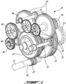
Fig. 2 is a schematic tridimensional view of a reduction gearbox according to a particular embodiment, which may be used in the engine ofFig. 1 ; -
Fig. 3 is a schematic cross-sectional view of the gearbox ofFig. 2 ; -
Fig. 4 is a schematic enlarged view of a portion of the gearbox ofFig. 2 , showing the gearbox in an engaged configuration; -
Fig. 5 is a schematic enlarged view of a portion of the gearbox ofFig. 2 , showing the gearbox in a disengaged configuration; and -
Fig. 6 is a schematic of pitch circles of the gears of the gearbox ofFig. 2 . -
Fig. 1 illustrates a turbopropgas turbine engine 10 of a type preferably provided for use in subsonic flights, generally comprising in serial flow communication anintake 12 through which air is drawn, acompressor section 14 for pressurizing the air, acombustor 16 in which the compressed air is mixed with fuel and ignited for generating an annular stream of hot combustion gases, and aturbine section 18 for extracting energy from the combustion gases. Apower shaft 15 connected to one or more turbine(s) of theturbines section 18 projects forwardly to transmit a driving force to anoutput shaft 19 including apropeller 21 via a reduction gearbox generally shown at 20. Thepower shaft 15 is also drivingly engaged through thereduction gearbox 20 to a plurality ofaccessories 22 and to agenerator 24, as will be further detailed below. - An exemplary embodiment of the
reduction gearbox 20 is shown inFigs. 2-6 . Thegearbox 20 is configured so as to be able to selectively drive thegenerator 24 andother accessories 22 together with theoutput shaft 19 andpropeller 21, or drive thegenerator 24 without driving theoutput shaft 19 and in a particular embodiment without driving theaccessories 22. This may allow theengine 10 to be used as an auxiliary power unit (APU) when on ground, which may eliminate the need for a separate APU to be provided in the aircraft. - Referring particularly to
Figs. 2-3 and6 , thepower shaft 15 has aninput pinion 26 connected thereto, and theoutput shaft 19 has anoutput gear 28 connected thereto. In the embodiment shown, theinput pinion 26 is directly connected to adrive shaft 30 which is configured as an extension of thepower shaft 15, i.e. coaxial with and directly connected to thepower shaft 15, and theoutput gear 28 is directly connected to theoutput shaft 19. Other configurations are also possible. - In the present specification, including claims, the term "drivingly engaged" is intended to include any engagement allowing two components to rotate together, at the same speed or at different speeds, and in the same direction or in different directions, including, but not limited to, direct connections, direct meshed engagement, engagement through meshing with one or more intermediate meshed element(s) (gear, pinion, etc.) and engagement through intermediate elements, e.g. idler gear.
- The
gearbox 20 has ainput gear 32 meshed with theinput pinion 26 of thepower shaft 15; in the embodiment shown, theinput gear 32 andinput pinion 26 are double helical gears. Thegearbox 20 also includes at least one output pinion 44 (two in the embodiment shown), each meshed with theoutput gear 28 of theoutput shaft 19; in the embodiment shown, theoutput pinions 44 andoutput gear 28 are also double helical gears. - The
gearbox 20 has agenerator drive gear 36 meshed with theinput gear 32, and which is also a helical gear. Thegenerator drive gear 36 is drivingly engaged to thegenerator 24. In the embodiment shown and referring also toFig. 6 , thegenerator drive gear 36 is an idler gear, mounted on a same shaft as anadditional idler gear 38 which is meshed with anadditional drive gear 40 directly connected to a rotatable shaft of thegenerator 22. Other configurations are also possible. - The
gearbox 20 is selectively configurable between an engaged configuration and a disengaged configuration. In the engaged configuration (Fig. 4 ), theinput gear 32 andoutput pinions 44 are drivingly engaged; in the disengaged configuration (Fig. 5 ), theinput gear 32 is rotatable independently of theoutput pinions 44. In the embodiment shown, the engagement between theinput gear 32 and theoutput pinions 44 is obtained through intermediate gears and pinions, as will be further detailed below. - Still referring to
Figs. 2-3 andFig. 6 , thegearbox 20 includes anintermediate pinion 34, which is drivingly engaged with theinput gear 32 in the engaged configuration and rotatable independently from theinput gear 32 in the disengaged configuration. The configuration of thegearbox 20 is thus changed by engaging or disengaging theinput gear 32 andintermediate pinion 34. - The
gearbox 20 of the embodiment shown further includes twointermediate gears 42 each drivingly engaged with a respective one of theoutput pinions 44. In the embodiment shown, thecorresponding output pinion 44 andintermediate gear 42 are drivingly engaged by a vernier spline coupling, such as to rotate together coaxially and at a same speed; the vernier spline couplings allow adjustment of load sharing between the two branches defined by the two sets of connectedpinion 44 andgear 42. Theintermediate gears 42 are meshed with theintermediate pinion 34; in the embodiment shown, theintermediate gears 42 andintermediate pinion 34 are spur gears. Alternately, a single set of drivingly engagedintermediate gear 42 andoutput pinion 44 may be provided. - The
gearbox 20 further includes anaccessory drive gear 46 meshed with one of theintermediate gears 42, and which is also a spur gear. Theaccessory drive gear 46 is drivingly engaged to one or more accessories 22 (e.g. hydraulic pump(s), propeller control components, gearbox oil pump, cooling fan, freon pump) of the aircraft. In the embodiment shown and referring particularly toFigs. 2 and6 , theaccessory drive gear 46 is an idler gear which is connected to a same shaft as an additionalidler spur gear 48 which is meshed with a first one of a respective series of meshedspur accessory gears 50, at least some of which being directly connected to a rotatable shaft of a respective accessory. Other configurations are also possible. - Although spur gear and double helical gears are shown and described, it is understood that any other adequate types of gears can be used in the
gearbox 20 and gears meshed therewith. In a particular embodiment, theinput pinion 26 andoutput gear 28 are axially fixed by thrust bearings of their respective shafts, and the intermediate spur pinion andgear gear gears input gear 32 and theoutput pinions 44 to float axially, and for the axial loads in each double helical mesh to be in equilibrium between the driving and driven gears. - Referring to
Figs. 4-5 , a particular embodiment for aconnection 52 allowing theintermediate pinion 34 andinput gear 32 to be selectively engageable and disengageable is shown and will be detailed below. It is understood that any other adequate type of connection or engagement can alternately be used. - Referring particularly to
Fig. 4 showing the engaged configuration, theintermediate pinion 34 andinput gear 32 are engaged through aslidable spline connection 52. When thespline connection 52 is engaged, theinput gear 32 andintermediate pinion 34 act as if connected to a same shaft, and are rotatable together coaxially and at a same speed. Theintermediate pinion 34 andinput gear 32 are relatively slidable so as to be able to disconnect thespline connection 52 for the disengaged configuration. - The
spline connection 52 is defined by two axially spaced apartteeth 54, 54' on each of theintermediate pinion 34 andinput gear 32, with theteeth 54, 54' of one of theintermediate pinion 34 andinput gear 32 defining a male spline (protuberance) while theteeth 54, 54' of the other of theintermediate pinion 34 andinput gear 32 define a female spline (slot), engaged one within the other in the engaged configuration. Theteeth 54, 54' are spaced apart an axial distance which is greater than the axial length of theteeth 54, 54'. Accordingly, in the disengaged configuration shown inFig. 5 , theteeth 54, 54' of theintermediate pinion 34 andinput gear 32 are disengaged and no longer axially aligned, and thus relatively rotatable without interference. - A clutch provides for the selective engagement of the
spline connection 52 between theintermediate pinion 34 andinput gear 32 to provide the relative sliding movement allowing to change the configuration of thegearbox 20. In the embodiment shown, the clutch includes ahydraulic actuator 56 including acylinder 58 attached to the housing of thegearbox 20, and apiston 60 slidable within thecylinder 58. Theinput gear 32 has a fixed axial position, and theintermediate pinion 34 is connected to thepiston 60. Theintermediate pinion 34 is thus axially movable with thepiston 60 to engage and disengage thespline connection 52. Thepiston 60 acts on theintermediate pinion 34 through a thrust split innerring ball bearing 62. Adedicated oil line 64 feeds anoil chamber 66 of thehydraulic cylinder 58 adjacent the head of thepiston 60. The clutch is thus activated by opening a valve (not shown) in theoil line 64, so that oil pressure in thechamber 66 acting on thepiston 60 moves theintermediate pinion 34 out of engagement with theinput gear 32. - In the embodiment shown, the
gearbox 20 is biased toward the engaged configuration. The oil pressure of theactuator 56 thus act against the biasing force of more spring(s) 68 (seeFig. 3 ), e.g. helical spring(s) upon movement toward the disengaged configuration. - The gears of the
reduction gearbox 20 thus define a transmission path having selectively engageable first and second portions, the first portion (which in the embodiment shown corresponds to the input gear 32) being meshed with theinput pinion 26 of thepower shaft 15 and with thegenerator drive gear 36 and the second portion (which in the embodiment shown includes theintermediate pinion 34, theintermediate gears 42 and the output pinions 44) being meshed with theoutput gear 28 of theoutput shaft 19. It is understood that other gear configurations than that shown can be provided in the first and second portions of the transmission path, including, but not limited to, a different number of gears and/or different types of gears and gear engagements. - In the engaged configuration, the first portion of the transmission path is drivingly engaged to the second portion of the transmission path, which allows the
input pinion 26 to drive thegenerator drive gear 36 andoutput gear 28 through thereduction gearbox 20; thegenerator 24 andpropeller 21 are thus driven together. In the disengaged configuration, the first portion of the transmission path is rotatable independently of the second portion of the transmission path because of the disconnectedspline connection 52 in thegearbox 20. This allows theinput pinion 26 to drive thegenerator drive gear 36 through thereduction gearbox 20 without driving theoutput gear 28; thegenerator 24 is thus driven without driving thepropeller 21. - With the
gearbox 20 in the disengaged configuration, theengine 10 may run at a setting required to provide pressurized air from thecompressor section 14 to meet the aircraft bleed requirements. - In the embodiment shown, the
accessory drive gear 46 is meshed with the second portion of the transmission path. Accordingly, when thegearbox 20 is in the engaged configuration, theaccessory drive gear 46 is drivable by theinput pinion 26, and when thegearbox 20 is in the disengaged configuration, theinput pinion 26 is rotatable without driving theaccessory drive gear 46. In cases when it would be desirable to driveaccessories 22 without driving thepropeller 21, theaccessory drive gear 46 can alternately be meshed with the first portion of the transmission path, or a respective accessory drive gear can be meshed with each portion of the transmission path so as to have only selected ones of theaccessories 22 being driven when rotation of thepropeller 21 is not driven. - Referring to
Fig. 6 , thegearbox 20 further includes abrake 70 selectively engageable with the second portion of the transmission path to selectively prevent rotation of thepropeller 21 when thegearbox 20 is in the disengaged configuration. In the embodiment shown, thebrake 70 includes a gear 72 (see alsoFig. 2 ) meshed with one of theintermediate gears 42 to selectively block its rotation. It is understood that thebrake 70 can engaged any other suitable element of thegearbox 20 or propeller assembly to allow for rotation of thepropeller 21 to be prevented. - In a particular embodiment, the gearbox can thus be configured to use a turboprop engine as an auxiliary power unit by maintaining an engagement of the first portion of the transmission path with the
generator 24 and with thepower shaft 15 while disengaging the second portion of the transmission path from the first portion of the transmission path. Disengaging the first portion of the transmission path from the second portion of the transmission path allows the first portion of the transmission path to be driven by thepower shaft 15 independently of the second portion of the transmission path. Rotation of thepropeller 21 is then prevented, for example by engaging thebrake 70 with the second portion of the transmission path. Thegenerator 24 can thus be driven independently of thepropeller 21. In the embodiment shown, disengaging the first and second portions of the transmission path includes axially sliding theintermediate pinion 34 to disengage theslidable spline connection 52 between theintermediate pinion 34 andinput gear 32, through actuation of thehydraulic actuator 56 against the biasing force of the spring(s) 68. - The
gearbox 20 advantageously allows theengine 10 to drive thegenerator 24 with thepower shaft 15 when the rotation of thepropeller 21 is prevented, i.e. to prevent rotation of thepropeller 21 without the need to prevent rotation of thepower shaft 15. In a particular embodiment, this allows for improved performances of theengine 10, as compared to a similar engine where thegenerator 24 is driven by the high pressure shaft with rotation of thepower shaft 15 being prevented. - The above description is meant to be exemplary only, and one skilled in the art will recognize that changes may be made to the embodiments described without departing from the scope of the invention disclosed. For example, the output gear could be used to drive a different load than a propeller. Still other modifications which fall within the scope of the present invention will be apparent to those skilled in the art, in light of a review of this disclosure, and such modifications are intended to fall within the appended claims.
Claims (15)
- A reduction gearbox (20) for an aircraft engine (10), the gearbox (20) comprising:an input pinion (26) configured to be driven by the aircraft engine (10);an input gear (32) meshed with the input pinion (26);a drive gear (36) meshed with the input gear (32);an output pinion (44), the reduction gearbox (20) being selectively configurable between an engaged configuration and a disengaged configuration, the input gear (32) and output pinion (44) being drivingly engaged in the engaged configuration, the input gear (32) being rotatable independently of the output pinion (44) in the disengaged configuration; andan output gear (28) meshed with the output pinion (44), the output gear (28) configured to drive an output shaft (19) of the aircraft engine (10).
- The reduction gearbox (20) as defined in claim 1, further comprising:an intermediate pinion (34) drivingly engaged to the input gear (32) in the engaged configuration and rotatable independently of the input gear (32) in the disengaged configuration; andan intermediate gear (42) meshed with the intermediate pinion (34), the intermediate gear (42) being drivingly engaged to the output pinion (44).
- The reduction gearbox (20) as defined in claim 2, further comprising a second drive gear (46) meshed with the intermediate gear (42).
- The reduction gearbox (20) as defined in claim 2 or 3, further comprising an additional intermediate gear (42) meshed with the intermediate pinion (34), and an additional output pinion (44) drivingly engaged with the additional intermediate gear (42), the output gear (28) being meshed with the additional output pinion (44).
- The reduction gearbox (20) as defined in claim 2, 3 or 4, wherein the intermediate pinion (34) and input gear (32) are engaged through a slidable spline connection (52), the intermediate pinion (34) and input gear (32) being relatively slidable so as to be interconnected by the spline connection (52) in the engaged configuration, the spline connection (52) being disconnected in the disengaged configuration.
- The reduction gearbox (20) as defined in claim 5, wherein one of the intermediate pinion (34) and input gear (32) is connected to a piston (60) of an actuator (56) actuable to provide the relative sliding movement between the engaged and disengaged configurations, and wherein, optionally, the piston (60) of the actuator (56) is actuable in one direction and biased in an opposed direction by a plurality of springs (68).
- The reduction gearbox (20) as defined in any preceding claim, further comprising a brake (70) selectively engageable with the reduction gearbox (20) to selectively prevent rotation of the output pinion (44).
- A turboprop engine (10) comprising:the reduction gearbox (20) of any of claims 1 to 6;a power shaft (15) rotatable by a turbine, the power shaft (15) connected to the input pinion (26);a generator (24) drivingly engaged to the drive gear (36);a propeller (21) rotatable by an output shaft (19), the output shaft (19) connected to the output gear (28), the reduction gearbox (20) having a plurality of drivingly engaged gears defining a transmission path, and the transmission path having a first portion meshed with the input pinion (26) and with the drive gear (36) and a second portion meshed with the output gear (28), wherein:in the engaged configuration, the first portion of the transmission path is drivingly engaged to the second portion of the transmission path, allowing the input pinion (26) to drive the drive gear (36) and output gear (28) through the reduction gearbox (20), andin the disengaged configuration, the first portion of the transmission path is rotatable independently of the second portion of the transmission path, allowing the input pinion (26) to drive the drive gear (36) through the reduction gearbox (20) without driving the output gear (28); anda brake (70) selectively engageable with the second portion of the transmission path to selectively prevent rotation of the propeller (21).
- The turboprop engine (10) as defined in claim 8, further comprising an accessory (22) drivingly engaged to an accessory drive gear (46), wherein the accessory drive gear (46) is meshed with the second portion of the transmission path, in the engaged configuration the accessory drive gear (46) is drivable by the input pinion (26), and in the disengaged configuration the input pinion (26) is rotatable without driving the accessory drive gear (46).
- The turboprop engine (10) as defined in claim 8 or 9, wherein the first portion of the transmission path is defined by the input gear (32) meshed with the input pinion (26) and with the drive gear (36), the input gear (32) being selectively engageable and disengageable from an adjacent gear of the second portion of the transmission path.
- The turboprop engine (10) as defined in claim 8, 9 or 10, wherein the first and second portions of the transmission path are biased toward the engaged configuration.
- A method of configuring a gearbox (20) for using a turboprop engine (10) as an auxiliary power unit, the gearbox (20) defining a transmission path between a power shaft (15) and a propeller (21) of the engine (10), the method comprising:maintaining an engagement of a first portion of the transmission path with a generator (24) and with the power shaft (15) while disengaging a second portion of the transmission path from the first portion of the transmission path, the second portion of the transmission path being drivingly engaged to the propeller (21), wherein disengaging the first portion of the transmission path from the second portion of the transmission path allows the first portion of the transmission path to be driven by the power shaft (15) independently of the second portion of the transmission path; andpreventing rotation of the propeller (21).
- The method as defined in claim 12, wherein preventing rotation of the propeller (21) includes engaging a brake (70) with the second portion of the transmission path.
- The method as defined in claim 12 or 13, wherein disengaging the second portion of the transmission path from the first portion of the transmission path includes disengaging a slidable spline connection (52) between two gears of the reduction gearbox (20).
- The method as defined in claim 14, wherein disengaging the slidable spline connection (52) includes producing a relative sliding movement between the two gears, and wherein, optionally, the relative sliding movement between the two gears is produced against a plurality of springs (68) biasing the transmission paths toward the engaged configuration.
Priority Applications (1)
| Application Number | Priority Date | Filing Date | Title |
|---|---|---|---|
| PL17175099T PL3257753T3 (en) | 2016-06-09 | 2017-06-08 | Reduction gearbox for aircraft engine |
Applications Claiming Priority (1)
| Application Number | Priority Date | Filing Date | Title |
|---|---|---|---|
| US15/177,783 US10400858B2 (en) | 2016-06-09 | 2016-06-09 | Reduction gearbox for aircraft engine |
Publications (2)
| Publication Number | Publication Date |
|---|---|
| EP3257753A1 true EP3257753A1 (en) | 2017-12-20 |
| EP3257753B1 EP3257753B1 (en) | 2019-05-22 |
Family
ID=59053971
Family Applications (1)
| Application Number | Title | Priority Date | Filing Date |
|---|---|---|---|
| EP17175099.5A Active EP3257753B1 (en) | 2016-06-09 | 2017-06-08 | Reduction gearbox for aircraft engine |
Country Status (4)
| Country | Link |
|---|---|
| US (1) | US10400858B2 (en) |
| EP (1) | EP3257753B1 (en) |
| CA (1) | CA2968553C (en) |
| PL (1) | PL3257753T3 (en) |
Cited By (1)
| Publication number | Priority date | Publication date | Assignee | Title |
|---|---|---|---|---|
| EP3584168A1 (en) * | 2018-06-20 | 2019-12-25 | Airbus Operations, S.L.U. | Turbomachinery for an aircraft |
Families Citing this family (12)
| Publication number | Priority date | Publication date | Assignee | Title |
|---|---|---|---|---|
| US11186378B2 (en) | 2019-03-29 | 2021-11-30 | Pratt & Whitney Canada Corp. | Hybrid aircraft propulsion power plants |
| CN111216884B (en) * | 2020-02-12 | 2022-11-15 | 西安爱生技术集团公司 | Automatic control device for engagement of box type launching unmanned aerial vehicle engine and propeller |
| US12241378B2 (en) * | 2021-01-26 | 2025-03-04 | Yantai Jereh Petroleum Equipment & Technologies Co., Ltd. | Gas turbine overspeed protection method and apparatus, electronic device and storage medium |
| US11867126B2 (en) | 2021-07-13 | 2024-01-09 | Pratt & Whitney Canada Corp. | Gas turbine engine and method of operation |
| US11905888B2 (en) | 2021-07-30 | 2024-02-20 | Pratt & Whitney Canada Corp. | Multi-engine system and power transfer between engines thereof |
| CN113639029B (en) * | 2021-08-16 | 2023-04-25 | 上海尚实航空发动机股份有限公司 | Vortex oar engine reduction gearbox unit body |
| US12378916B2 (en) * | 2022-11-18 | 2025-08-05 | Pratt & Whitney Canada Corp. | Engine power extraction system and method for using same |
| FR3145392B1 (en) * | 2023-01-31 | 2025-01-17 | Safran Trans Systems | TURBOMACHINE COMPRISING A SPEED REDUCER AND AT LEAST ONE ELECTRIC MACHINE. |
| FR3145391B1 (en) * | 2023-01-31 | 2025-04-25 | Safran Trans Systems | TURBOMACHINE COMPRISING A SPEED REDUCER INCORPORATING AN ELECTRIC MACHINE. |
| US12060832B1 (en) * | 2023-03-16 | 2024-08-13 | Pratt & Whitney Canada Corp. | Aircraft engine fluid system with shut-off valve |
| US12584446B2 (en) * | 2023-06-21 | 2026-03-24 | General Electric Company | Unidirectional fan brake for a gas turbine engine |
| US20260043355A1 (en) * | 2024-08-06 | 2026-02-12 | The Boeing Company | System to Selectively Transfer Power of a Turbine Engine |
Citations (2)
| Publication number | Priority date | Publication date | Assignee | Title |
|---|---|---|---|---|
| US20090227415A1 (en) * | 2008-03-06 | 2009-09-10 | Karem Aircraft, Inc. | Torque Balancing Gearbox |
| EP3002435A1 (en) * | 2014-10-03 | 2016-04-06 | Pratt & Whitney Canada Corp. | Accessory drive system for a gas turbine engine |
Family Cites Families (9)
| Publication number | Priority date | Publication date | Assignee | Title |
|---|---|---|---|---|
| GB2196390B (en) * | 1986-10-16 | 1991-06-26 | Rolls Royce Plc | Intake for turbopropeller gas turbine engine. |
| US7121078B2 (en) * | 2003-01-28 | 2006-10-17 | General Electric Company | Methods and apparatus for operating gas turbine engines |
| US20060137355A1 (en) | 2004-12-27 | 2006-06-29 | Pratt & Whitney Canada Corp. | Fan driven emergency generator |
| GB0809336D0 (en) | 2008-05-23 | 2008-07-02 | Rolls Royce Plc | A gas turbine engine arrangement |
| US20100162719A1 (en) * | 2008-12-31 | 2010-07-01 | Bowman Ray F | Gas turbine engine |
| GB0903423D0 (en) | 2009-03-02 | 2009-04-08 | Rolls Royce Plc | Variable drive gas turbine engine |
| US8943839B2 (en) | 2011-08-26 | 2015-02-03 | United Technologies Corporation | Gas turbine engine generator switchable drive |
| US9428267B2 (en) * | 2014-01-06 | 2016-08-30 | Sikorsky Aircraft Corporation | In-flight mechanically assisted turbine engine starting system |
| US10850863B2 (en) | 2014-03-04 | 2020-12-01 | Pratt & Whitney Canada Corp. | System and method for operating a multi-engine aircraft in an auxiliary power unit mode |
-
2016
- 2016-06-09 US US15/177,783 patent/US10400858B2/en active Active
-
2017
- 2017-05-25 CA CA2968553A patent/CA2968553C/en active Active
- 2017-06-08 EP EP17175099.5A patent/EP3257753B1/en active Active
- 2017-06-08 PL PL17175099T patent/PL3257753T3/en unknown
Patent Citations (2)
| Publication number | Priority date | Publication date | Assignee | Title |
|---|---|---|---|---|
| US20090227415A1 (en) * | 2008-03-06 | 2009-09-10 | Karem Aircraft, Inc. | Torque Balancing Gearbox |
| EP3002435A1 (en) * | 2014-10-03 | 2016-04-06 | Pratt & Whitney Canada Corp. | Accessory drive system for a gas turbine engine |
Cited By (1)
| Publication number | Priority date | Publication date | Assignee | Title |
|---|---|---|---|---|
| EP3584168A1 (en) * | 2018-06-20 | 2019-12-25 | Airbus Operations, S.L.U. | Turbomachinery for an aircraft |
Also Published As
| Publication number | Publication date |
|---|---|
| CA2968553C (en) | 2024-01-09 |
| PL3257753T3 (en) | 2020-03-31 |
| US20170356525A1 (en) | 2017-12-14 |
| CA2968553A1 (en) | 2017-12-09 |
| US10400858B2 (en) | 2019-09-03 |
| EP3257753B1 (en) | 2019-05-22 |
Similar Documents
| Publication | Publication Date | Title |
|---|---|---|
| EP3257753B1 (en) | Reduction gearbox for aircraft engine | |
| US12158111B2 (en) | Planetary gearbox for gas turbine engine | |
| EP2964921B1 (en) | Multi-shaft gas turbine engine | |
| US10113482B2 (en) | Gearbox for gas turbine engine | |
| EP3859134B1 (en) | Multi-engine aircraft and method of operating a multi-engine aircraft | |
| US10815900B2 (en) | Geared gas turbine engine | |
| US7758302B2 (en) | Device for the offtake of mechanical power between the HP and LP shafts of a double-shaft turbine engine | |
| EP2553251B1 (en) | Adaptive fan system for a variable cycle turbofan engine | |
| EP3121469A1 (en) | Drive shaft assembly | |
| CN109312668B (en) | Air turbine starter with decoupler | |
| US10683900B2 (en) | Clutch device for gas turbine engines | |
| CA3011586C (en) | Engine internal coupling arrangment | |
| US11603890B2 (en) | Driveline engagement system |
Legal Events
| Date | Code | Title | Description |
|---|---|---|---|
| PUAI | Public reference made under article 153(3) epc to a published international application that has entered the european phase |
Free format text: ORIGINAL CODE: 0009012 |
|
| STAA | Information on the status of an ep patent application or granted ep patent |
Free format text: STATUS: THE APPLICATION HAS BEEN PUBLISHED |
|
| AK | Designated contracting states |
Kind code of ref document: A1 Designated state(s): AL AT BE BG CH CY CZ DE DK EE ES FI FR GB GR HR HU IE IS IT LI LT LU LV MC MK MT NL NO PL PT RO RS SE SI SK SM TR |
|
| AX | Request for extension of the european patent |
Extension state: BA ME |
|
| STAA | Information on the status of an ep patent application or granted ep patent |
Free format text: STATUS: REQUEST FOR EXAMINATION WAS MADE |
|
| 17P | Request for examination filed |
Effective date: 20180619 |
|
| RBV | Designated contracting states (corrected) |
Designated state(s): AL AT BE BG CH CY CZ DE DK EE ES FI FR GB GR HR HU IE IS IT LI LT LU LV MC MK MT NL NO PL PT RO RS SE SI SK SM TR |
|
| GRAP | Despatch of communication of intention to grant a patent |
Free format text: ORIGINAL CODE: EPIDOSNIGR1 |
|
| STAA | Information on the status of an ep patent application or granted ep patent |
Free format text: STATUS: GRANT OF PATENT IS INTENDED |
|
| RIC1 | Information provided on ipc code assigned before grant |
Ipc: B64D 35/00 20060101AFI20181112BHEP |
|
| INTG | Intention to grant announced |
Effective date: 20181128 |
|
| GRAS | Grant fee paid |
Free format text: ORIGINAL CODE: EPIDOSNIGR3 |
|
| GRAA | (expected) grant |
Free format text: ORIGINAL CODE: 0009210 |
|
| STAA | Information on the status of an ep patent application or granted ep patent |
Free format text: STATUS: THE PATENT HAS BEEN GRANTED |
|
| AK | Designated contracting states |
Kind code of ref document: B1 Designated state(s): AL AT BE BG CH CY CZ DE DK EE ES FI FR GB GR HR HU IE IS IT LI LT LU LV MC MK MT NL NO PL PT RO RS SE SI SK SM TR |
|
| REG | Reference to a national code |
Ref country code: GB Ref legal event code: FG4D |
|
| REG | Reference to a national code |
Ref country code: CH Ref legal event code: EP |
|
| REG | Reference to a national code |
Ref country code: IE Ref legal event code: FG4D |
|
| REG | Reference to a national code |
Ref country code: DE Ref legal event code: R096 Ref document number: 602017004064 Country of ref document: DE |
|
| REG | Reference to a national code |
Ref country code: AT Ref legal event code: REF Ref document number: 1135801 Country of ref document: AT Kind code of ref document: T Effective date: 20190615 |
|
| REG | Reference to a national code |
Ref country code: NL Ref legal event code: MP Effective date: 20190522 |
|
| REG | Reference to a national code |
Ref country code: LT Ref legal event code: MG4D |
|
| PG25 | Lapsed in a contracting state [announced via postgrant information from national office to epo] |
Ref country code: ES Free format text: LAPSE BECAUSE OF FAILURE TO SUBMIT A TRANSLATION OF THE DESCRIPTION OR TO PAY THE FEE WITHIN THE PRESCRIBED TIME-LIMIT Effective date: 20190522 Ref country code: NL Free format text: LAPSE BECAUSE OF FAILURE TO SUBMIT A TRANSLATION OF THE DESCRIPTION OR TO PAY THE FEE WITHIN THE PRESCRIBED TIME-LIMIT Effective date: 20190522 Ref country code: LT Free format text: LAPSE BECAUSE OF FAILURE TO SUBMIT A TRANSLATION OF THE DESCRIPTION OR TO PAY THE FEE WITHIN THE PRESCRIBED TIME-LIMIT Effective date: 20190522 Ref country code: HR Free format text: LAPSE BECAUSE OF FAILURE TO SUBMIT A TRANSLATION OF THE DESCRIPTION OR TO PAY THE FEE WITHIN THE PRESCRIBED TIME-LIMIT Effective date: 20190522 Ref country code: AL Free format text: LAPSE BECAUSE OF FAILURE TO SUBMIT A TRANSLATION OF THE DESCRIPTION OR TO PAY THE FEE WITHIN THE PRESCRIBED TIME-LIMIT Effective date: 20190522 Ref country code: FI Free format text: LAPSE BECAUSE OF FAILURE TO SUBMIT A TRANSLATION OF THE DESCRIPTION OR TO PAY THE FEE WITHIN THE PRESCRIBED TIME-LIMIT Effective date: 20190522 Ref country code: PT Free format text: LAPSE BECAUSE OF FAILURE TO SUBMIT A TRANSLATION OF THE DESCRIPTION OR TO PAY THE FEE WITHIN THE PRESCRIBED TIME-LIMIT Effective date: 20190922 Ref country code: NO Free format text: LAPSE BECAUSE OF FAILURE TO SUBMIT A TRANSLATION OF THE DESCRIPTION OR TO PAY THE FEE WITHIN THE PRESCRIBED TIME-LIMIT Effective date: 20190822 Ref country code: SE Free format text: LAPSE BECAUSE OF FAILURE TO SUBMIT A TRANSLATION OF THE DESCRIPTION OR TO PAY THE FEE WITHIN THE PRESCRIBED TIME-LIMIT Effective date: 20190522 |
|
| PG25 | Lapsed in a contracting state [announced via postgrant information from national office to epo] |
Ref country code: LV Free format text: LAPSE BECAUSE OF FAILURE TO SUBMIT A TRANSLATION OF THE DESCRIPTION OR TO PAY THE FEE WITHIN THE PRESCRIBED TIME-LIMIT Effective date: 20190522 Ref country code: GR Free format text: LAPSE BECAUSE OF FAILURE TO SUBMIT A TRANSLATION OF THE DESCRIPTION OR TO PAY THE FEE WITHIN THE PRESCRIBED TIME-LIMIT Effective date: 20190823 Ref country code: RS Free format text: LAPSE BECAUSE OF FAILURE TO SUBMIT A TRANSLATION OF THE DESCRIPTION OR TO PAY THE FEE WITHIN THE PRESCRIBED TIME-LIMIT Effective date: 20190522 Ref country code: BG Free format text: LAPSE BECAUSE OF FAILURE TO SUBMIT A TRANSLATION OF THE DESCRIPTION OR TO PAY THE FEE WITHIN THE PRESCRIBED TIME-LIMIT Effective date: 20190822 |
|
| REG | Reference to a national code |
Ref country code: AT Ref legal event code: MK05 Ref document number: 1135801 Country of ref document: AT Kind code of ref document: T Effective date: 20190522 |
|
| PG25 | Lapsed in a contracting state [announced via postgrant information from national office to epo] |
Ref country code: RO Free format text: LAPSE BECAUSE OF FAILURE TO SUBMIT A TRANSLATION OF THE DESCRIPTION OR TO PAY THE FEE WITHIN THE PRESCRIBED TIME-LIMIT Effective date: 20190522 Ref country code: SK Free format text: LAPSE BECAUSE OF FAILURE TO SUBMIT A TRANSLATION OF THE DESCRIPTION OR TO PAY THE FEE WITHIN THE PRESCRIBED TIME-LIMIT Effective date: 20190522 Ref country code: EE Free format text: LAPSE BECAUSE OF FAILURE TO SUBMIT A TRANSLATION OF THE DESCRIPTION OR TO PAY THE FEE WITHIN THE PRESCRIBED TIME-LIMIT Effective date: 20190522 Ref country code: AT Free format text: LAPSE BECAUSE OF FAILURE TO SUBMIT A TRANSLATION OF THE DESCRIPTION OR TO PAY THE FEE WITHIN THE PRESCRIBED TIME-LIMIT Effective date: 20190522 Ref country code: DK Free format text: LAPSE BECAUSE OF FAILURE TO SUBMIT A TRANSLATION OF THE DESCRIPTION OR TO PAY THE FEE WITHIN THE PRESCRIBED TIME-LIMIT Effective date: 20190522 |
|
| REG | Reference to a national code |
Ref country code: DE Ref legal event code: R097 Ref document number: 602017004064 Country of ref document: DE |
|
| PG25 | Lapsed in a contracting state [announced via postgrant information from national office to epo] |
Ref country code: IT Free format text: LAPSE BECAUSE OF FAILURE TO SUBMIT A TRANSLATION OF THE DESCRIPTION OR TO PAY THE FEE WITHIN THE PRESCRIBED TIME-LIMIT Effective date: 20190522 Ref country code: SM Free format text: LAPSE BECAUSE OF FAILURE TO SUBMIT A TRANSLATION OF THE DESCRIPTION OR TO PAY THE FEE WITHIN THE PRESCRIBED TIME-LIMIT Effective date: 20190522 Ref country code: MC Free format text: LAPSE BECAUSE OF FAILURE TO SUBMIT A TRANSLATION OF THE DESCRIPTION OR TO PAY THE FEE WITHIN THE PRESCRIBED TIME-LIMIT Effective date: 20190522 |
|
| PLBE | No opposition filed within time limit |
Free format text: ORIGINAL CODE: 0009261 |
|
| REG | Reference to a national code |
Ref country code: BE Ref legal event code: MM Effective date: 20190630 |
|
| STAA | Information on the status of an ep patent application or granted ep patent |
Free format text: STATUS: NO OPPOSITION FILED WITHIN TIME LIMIT |
|
| PG25 | Lapsed in a contracting state [announced via postgrant information from national office to epo] |
Ref country code: TR Free format text: LAPSE BECAUSE OF FAILURE TO SUBMIT A TRANSLATION OF THE DESCRIPTION OR TO PAY THE FEE WITHIN THE PRESCRIBED TIME-LIMIT Effective date: 20190522 |
|
| 26N | No opposition filed |
Effective date: 20200225 |
|
| PG25 | Lapsed in a contracting state [announced via postgrant information from national office to epo] |
Ref country code: IE Free format text: LAPSE BECAUSE OF NON-PAYMENT OF DUE FEES Effective date: 20190608 |
|
| PG25 | Lapsed in a contracting state [announced via postgrant information from national office to epo] |
Ref country code: SI Free format text: LAPSE BECAUSE OF FAILURE TO SUBMIT A TRANSLATION OF THE DESCRIPTION OR TO PAY THE FEE WITHIN THE PRESCRIBED TIME-LIMIT Effective date: 20190522 Ref country code: LU Free format text: LAPSE BECAUSE OF NON-PAYMENT OF DUE FEES Effective date: 20190608 Ref country code: BE Free format text: LAPSE BECAUSE OF NON-PAYMENT OF DUE FEES Effective date: 20190630 |
|
| REG | Reference to a national code |
Ref country code: CH Ref legal event code: PL |
|
| PG25 | Lapsed in a contracting state [announced via postgrant information from national office to epo] |
Ref country code: CH Free format text: LAPSE BECAUSE OF NON-PAYMENT OF DUE FEES Effective date: 20200630 Ref country code: LI Free format text: LAPSE BECAUSE OF NON-PAYMENT OF DUE FEES Effective date: 20200630 |
|
| PG25 | Lapsed in a contracting state [announced via postgrant information from national office to epo] |
Ref country code: CY Free format text: LAPSE BECAUSE OF FAILURE TO SUBMIT A TRANSLATION OF THE DESCRIPTION OR TO PAY THE FEE WITHIN THE PRESCRIBED TIME-LIMIT Effective date: 20190522 |
|
| PG25 | Lapsed in a contracting state [announced via postgrant information from national office to epo] |
Ref country code: IS Free format text: LAPSE BECAUSE OF FAILURE TO SUBMIT A TRANSLATION OF THE DESCRIPTION OR TO PAY THE FEE WITHIN THE PRESCRIBED TIME-LIMIT Effective date: 20190922 |
|
| PG25 | Lapsed in a contracting state [announced via postgrant information from national office to epo] |
Ref country code: MT Free format text: LAPSE BECAUSE OF FAILURE TO SUBMIT A TRANSLATION OF THE DESCRIPTION OR TO PAY THE FEE WITHIN THE PRESCRIBED TIME-LIMIT Effective date: 20190522 Ref country code: HU Free format text: LAPSE BECAUSE OF FAILURE TO SUBMIT A TRANSLATION OF THE DESCRIPTION OR TO PAY THE FEE WITHIN THE PRESCRIBED TIME-LIMIT; INVALID AB INITIO Effective date: 20170608 |
|
| PG25 | Lapsed in a contracting state [announced via postgrant information from national office to epo] |
Ref country code: MK Free format text: LAPSE BECAUSE OF FAILURE TO SUBMIT A TRANSLATION OF THE DESCRIPTION OR TO PAY THE FEE WITHIN THE PRESCRIBED TIME-LIMIT Effective date: 20190522 |
|
| P01 | Opt-out of the competence of the unified patent court (upc) registered |
Effective date: 20230530 |
|
| PGFP | Annual fee paid to national office [announced via postgrant information from national office to epo] |
Ref country code: PL Payment date: 20250522 Year of fee payment: 9 Ref country code: DE Payment date: 20250520 Year of fee payment: 9 |
|
| PGFP | Annual fee paid to national office [announced via postgrant information from national office to epo] |
Ref country code: GB Payment date: 20250520 Year of fee payment: 9 |
|
| PGFP | Annual fee paid to national office [announced via postgrant information from national office to epo] |
Ref country code: FR Payment date: 20250520 Year of fee payment: 9 |
|
| PGFP | Annual fee paid to national office [announced via postgrant information from national office to epo] |
Ref country code: CZ Payment date: 20250528 Year of fee payment: 9 |