EP3257622A1 - Fixture for holding a part during a machining operation - Google Patents
Fixture for holding a part during a machining operation Download PDFInfo
- Publication number
- EP3257622A1 EP3257622A1 EP17171324.1A EP17171324A EP3257622A1 EP 3257622 A1 EP3257622 A1 EP 3257622A1 EP 17171324 A EP17171324 A EP 17171324A EP 3257622 A1 EP3257622 A1 EP 3257622A1
- Authority
- EP
- European Patent Office
- Prior art keywords
- fixture
- lever
- linkage arm
- engagement device
- fulcrum
- Prior art date
- Legal status (The legal status is an assumption and is not a legal conclusion. Google has not performed a legal analysis and makes no representation as to the accuracy of the status listed.)
- Granted
Links
Images


Classifications
-
- B—PERFORMING OPERATIONS; TRANSPORTING
- B25—HAND TOOLS; PORTABLE POWER-DRIVEN TOOLS; MANIPULATORS
- B25B—TOOLS OR BENCH DEVICES NOT OTHERWISE PROVIDED FOR, FOR FASTENING, CONNECTING, DISENGAGING, OR HOLDING
- B25B5/00—Clamps
- B25B5/06—Arrangements for positively actuating jaws
- B25B5/10—Arrangements for positively actuating jaws using screws
- B25B5/104—Arrangements for positively actuating jaws using screws with one screw and one clamping lever and one fulcrum element
- B25B5/108—Arrangements for positively actuating jaws using screws with one screw and one clamping lever and one fulcrum element the screw contacting one of the ends of the lever
-
- B—PERFORMING OPERATIONS; TRANSPORTING
- B23—MACHINE TOOLS; METAL-WORKING NOT OTHERWISE PROVIDED FOR
- B23Q—DETAILS, COMPONENTS, OR ACCESSORIES FOR MACHINE TOOLS, e.g. ARRANGEMENTS FOR COPYING OR CONTROLLING; MACHINE TOOLS IN GENERAL CHARACTERISED BY THE CONSTRUCTION OF PARTICULAR DETAILS OR COMPONENTS; COMBINATIONS OR ASSOCIATIONS OF METAL-WORKING MACHINES, NOT DIRECTED TO A PARTICULAR RESULT
- B23Q3/00—Devices holding, supporting, or positioning work or tools, of a kind normally removable from the machine
- B23Q3/02—Devices holding, supporting, or positioning work or tools, of a kind normally removable from the machine for mounting on a work-table, tool-slide, or analogous part
- B23Q3/06—Work-clamping means
- B23Q3/062—Work-clamping means adapted for holding workpieces having a special form or being made from a special material
-
- B—PERFORMING OPERATIONS; TRANSPORTING
- B25—HAND TOOLS; PORTABLE POWER-DRIVEN TOOLS; MANIPULATORS
- B25B—TOOLS OR BENCH DEVICES NOT OTHERWISE PROVIDED FOR, FOR FASTENING, CONNECTING, DISENGAGING, OR HOLDING
- B25B5/00—Clamps
- B25B5/006—Supporting devices for clamps
-
- B—PERFORMING OPERATIONS; TRANSPORTING
- B25—HAND TOOLS; PORTABLE POWER-DRIVEN TOOLS; MANIPULATORS
- B25B—TOOLS OR BENCH DEVICES NOT OTHERWISE PROVIDED FOR, FOR FASTENING, CONNECTING, DISENGAGING, OR HOLDING
- B25B5/00—Clamps
- B25B5/14—Clamps for work of special profile
-
- B—PERFORMING OPERATIONS; TRANSPORTING
- B25—HAND TOOLS; PORTABLE POWER-DRIVEN TOOLS; MANIPULATORS
- B25B—TOOLS OR BENCH DEVICES NOT OTHERWISE PROVIDED FOR, FOR FASTENING, CONNECTING, DISENGAGING, OR HOLDING
- B25B1/00—Vices
- B25B1/24—Details, e.g. jaws of special shape, slideways
- B25B1/2405—Construction of the jaws
- B25B1/2457—Construction of the jaws with auxiliary attachments
- B25B1/2463—Supports for the workpiece
Definitions
- the present invention is concerned with a fixture for holding a part during a machining operation. More particularly, the invention is concerned with a fixture for holding a part which includes a hooked or lipped portion and holding said part securely in position whilst leaving the surfaces to be machined accessible.
- the invention has particular application (but is not strictly limited to) the machining of seal segment carriers for gas turbine engines.
- Gas turbine engine parts are conventionally manufactured by an investment casting process. This process inherently has limits on how accurately dimensions, in particular small dimensions, can be made. Consequently, it is known to undertake additional machining operations on cast parts to, for example, refine dimensions, provide more intricate detail in features and improve surface finishing of the part.
- Figure 1 shows a prior known fixture.
- the fixture comprises a baseplate 1 having an orthogonally extending side wall 5.
- Three clamps are arranged to hold a part on one of three orthogonal planes X, Y and Z.
- a first clamp 6 clamping in an X-plane, a series of two clamps 2 and 3 clamping in a Y plane and a third clamp 4 clamping in a Z plane.
- the Y and Z clamps are pivotal into and out of position by means of pivot 2a, 3a, 4a and can be latched into position by means of catches 2b, 3b, 4b extending from the side wall 5 and baseplate 1.
- the third clamp Z also includes a hinge 4b allowing an end of the clamp to be raised and lowered with respect to the base plate 1.
- the X clamp is a screw jack clamp with a swivel face end allowing engagement onto an uneven surface.
- a fixture for holding a part comprising; a frame supporting a guide plate; a controlled engagement device passing through the guide plate and arranged to be advanced incrementally towards a first end of a fulcrum beam; a second end of the fulcrum beam connected to a linkage arm; the linkage arm passing through a gap in the guide plate; an end of the linkage arm distal to the fulcrum beam having mounted thereto a swivel clamp; a support arranged to face the swivel clamp and defining a space therebetween, the space configured to receive a part to be clamped in the fixture.
- a fulcrum beam (“lever”) is arranged to pivot about a pivot point ("fulcrum").
- the controlled engagement device is arranged to engage with the fulcrum beam on a first side of the pivot point and the linkage arm is connected to the lever on a second side of the fulcrum.
- the controlled engagement device is a bolt and the guide plate comprises a threaded orifice into which a mating thread of the bolt engages, the fastener being advanceable by means of screwing the bolt into the threaded orifice.
- the controlled engagement device has a rounded surface at an end which advances towards the lever.
- the frame includes a base plate towards which the controlled engagement device may advance whereby to clamp the component by advancing one end of the lever towards the base plate.
- the base plate may further include a rounded sprung plunger aligned with the axis of the controlled engagement device such that, on advancement of the controlled engagement device, the lever can be engaged between the base plate sprung plunger and the controlled engagement device.
- the fixture may further include a cradle arranged in the space between the support and the swivel clamp into which a part may be received.
- the frame may further be supplied with guides or stops arranged to restrict non-rotational movement of the linkage arm and/or the lever.
- Locators may be provided on the support and/or the cradle around which recesses in a part can be located.
- the locators may be arranged to serve as datum for machining of a part.
- the locators may be adjustable to allow accurate positioning of a datum.
- adjustable locators comprise threaded barrels arranged on screws, screwing of the barrel in either direction allows repositioning of a datum.
- the swivel clamp may be selectively shaped to provide a clamping force on appropriate surfaces of a part to be held in the fixture.
- the swivel clamp may include a replaceable pad such that pads of different shapes can be interchanged to suit different part geometries.
- connection between the linkage arm and the lever is configured to allow the linkage arm to be repositioned relative to a fulcrum.
- the connection comprises an elongate slot in the lever and a dowel which passes through the elongate slot and a dowel sized hole in the linkage arm.
- the dowel can slide to a desired position within the slot during clamping to allow the linkage arm to raise through the guide slot allowing movement of the linkage arm and lever together.
- the linkage arm may comprise a plurality of sized holes to allow further configurations of the fixture. This can optionally use a bolt in place of a dowel and also could have the plurality of hole sizes within the lever and an oversized hole within the linkage arm to allow movement.
- the fixture of the invention permits locking off of a part within the fixture by means of a single fastener.
- the arrangement uses the fulcrum and lever arrangement to apply a clamping force in a direction opposite to which the fastener is advanced against the lever. As the fastener is advanced it applies pressure to the lever which pivots on the fulcrum lifting the linkage arm.
- the arrangement locates the swivel clamp on the part repeatably to apply the required force to trap the part in place.
- Materials and shape of the fixture can be varied to suit specific part geometries and materials.
- the required force to be applied by the clamp can be calculated for a given application.
- Balance dowels and additional guides/stops can be positioned to suit part machining requirements.
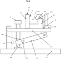
- the fixture of Figures 2 and 3 comprises a guide plate 21 having an aperture through which a controlled engagement device such as bolt 25 is threaded.
- the bolt 25 has a rounded end 25a which, when suitably advanced through the aperture engages with and pushes against a first end of a lever 22.
- a rounded sprung plunger 26 is fixed in axial alignment with the aperture and bolt 25 such that the lever 22 can be pushed against the sprung plunger 26 by the advancing bolt 25 until the mechanism is secured into a position against the component the sprung plunger 26 allows the lever 22 to return to its starting position once the controlled engagement device is retracted unclamping the component.
- the lever 22 is pivoted on fulcrum 22a.
- the lever 22 attaches to a first end of a linkage arm 23 which passes through a gap 28b in the guide plate 21.
- a swivel clamp 24 is mounted for rotation about the fulcrum 24a.
- the lever 22 tilts and, by means of the linkage arm 23, advances the swivel clamp 24 towards a support 27.
- the support 27 and a cradle 30 define a space 31 into which a part can be located.
- the swivel clamp 24 engages with a part located in the cradle 31 and secures the part in position.
- the rotational position of the swivel clamp can be locked independently.
- Advancement of the bolt 25 secures the lever 22, linkage arm 23 and swivel clamp 24 in spatial position.
- Stop 28 locates the component within the X direction on the fixture.
- a part may be locatable onto locators 32 which can serve as a datum for subsequent manufacturing operations. Some or all of the locators 32 may be adjustable, for example by screwing a threaded barrel in opposite directions along an inner screw to allow accurate positioning of the datum.
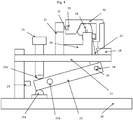
- Figure 4 shows a part 40 in position in the fixture of Figures 2 and 3 .
- the part locates on locators 32 and around swivel clamp 24.
- the swivel clamp 24 can be used to clamp the part 40 into position.
- the fixture is more compact whilst robust and low maintenance.
- the simplicity of the arrangement permits quick, easy and repeatable loading.
- the arrangement leaves multiple surfaces of a part accessible to machine tools reducing the need to reposition the part between machining or finishing operations.
- a further benefit of the arrangement arises from the use of linkages to put the required clamping force at a desired location on the part. This is in contrast to the use of maximum clamping forces which can result in surface damage to the part.
- the arrangement is particularly useful for providing repeatable loading against datum locations on hooked and lipped parts.
Landscapes
- Engineering & Computer Science (AREA)
- Mechanical Engineering (AREA)
- Jigs For Machine Tools (AREA)
- Machine Tool Units (AREA)
Abstract
Description
- The present invention is concerned with a fixture for holding a part during a machining operation. More particularly, the invention is concerned with a fixture for holding a part which includes a hooked or lipped portion and holding said part securely in position whilst leaving the surfaces to be machined accessible. The invention has particular application (but is not strictly limited to) the machining of seal segment carriers for gas turbine engines.
- Gas turbine engine parts are conventionally manufactured by an investment casting process. This process inherently has limits on how accurately dimensions, in particular small dimensions, can be made. Consequently, it is known to undertake additional machining operations on cast parts to, for example, refine dimensions, provide more intricate detail in features and improve surface finishing of the part.
-
Figure 1 shows a prior known fixture. As can be seen the fixture comprises abaseplate 1 having an orthogonally extendingside wall 5. Three clamps are arranged to hold a part on one of three orthogonal planes X, Y and Z. Afirst clamp 6 clamping in an X-plane, a series of twoclamps third clamp 4 clamping in a Z plane. The Y and Z clamps are pivotal into and out of position by means ofpivot catches side wall 5 andbaseplate 1. The third clamp Z also includes ahinge 4b allowing an end of the clamp to be raised and lowered with respect to thebase plate 1. The X clamp is a screw jack clamp with a swivel face end allowing engagement onto an uneven surface. - As can be seen, little of a clamped part is left accessible. Consequently a part may need to be repositioned in to fixtures multiple times for performing multiple machining/finishing operations. This is both time consuming and, since no one datum is fixed in position, the results after multiple operations are variable. Consequently, quality and conformity of parts to a desired specification may not be consistent. Accurate location of small parts is particularly challenging.
- It is an object of the invention to provide a fixture which can hold a part securely during machining operations and which provides access to multiple surfaces reducing the need for repositioning the part between multiple machining operations.
- In accordance with the present invention there is provided a fixture for holding a part, the fixture comprising;
a frame supporting a guide plate; a controlled engagement device passing through the guide plate and arranged to be advanced incrementally towards a first end of a fulcrum beam; a second end of the fulcrum beam connected to a linkage arm; the linkage arm passing through a gap in the guide plate; an end of the linkage arm distal to the fulcrum beam having mounted thereto a swivel clamp; a support arranged to face the swivel clamp and defining a space therebetween, the space configured to receive a part to be clamped in the fixture. - It will be understood that a fulcrum beam ("lever") is arranged to pivot about a pivot point ("fulcrum"). The controlled engagement device is arranged to engage with the fulcrum beam on a first side of the pivot point and the linkage arm is connected to the lever on a second side of the fulcrum.
- For example, the controlled engagement device is a bolt and the guide plate comprises a threaded orifice into which a mating thread of the bolt engages, the fastener being advanceable by means of screwing the bolt into the threaded orifice. Optionally the controlled engagement device has a rounded surface at an end which advances towards the lever. Optionally, the frame includes a base plate towards which the controlled engagement device may advance whereby to clamp the component by advancing one end of the lever towards the base plate. The base plate may further include a rounded sprung plunger aligned with the axis of the controlled engagement device such that, on advancement of the controlled engagement device, the lever can be engaged between the base plate sprung plunger and the controlled engagement device.
- The fixture may further include a cradle arranged in the space between the support and the swivel clamp into which a part may be received. The frame may further be supplied with guides or stops arranged to restrict non-rotational movement of the linkage arm and/or the lever.
- Locators may be provided on the support and/or the cradle around which recesses in a part can be located. The locators may be arranged to serve as datum for machining of a part. The locators may be adjustable to allow accurate positioning of a datum. For example, adjustable locators comprise threaded barrels arranged on screws, screwing of the barrel in either direction allows repositioning of a datum.
- The swivel clamp may be selectively shaped to provide a clamping force on appropriate surfaces of a part to be held in the fixture. The swivel clamp may include a replaceable pad such that pads of different shapes can be interchanged to suit different part geometries.
- Optionally, the connection between the linkage arm and the lever is configured to allow the linkage arm to be repositioned relative to a fulcrum. For example, the connection comprises an elongate slot in the lever and a dowel which passes through the elongate slot and a dowel sized hole in the linkage arm. The dowel can slide to a desired position within the slot during clamping to allow the linkage arm to raise through the guide slot allowing movement of the linkage arm and lever together. In a further option, the linkage arm may comprise a plurality of sized holes to allow further configurations of the fixture. This can optionally use a bolt in place of a dowel and also could have the plurality of hole sizes within the lever and an oversized hole within the linkage arm to allow movement.
- It will be appreciated that the fixture of the invention permits locking off of a part within the fixture by means of a single fastener. The arrangement uses the fulcrum and lever arrangement to apply a clamping force in a direction opposite to which the fastener is advanced against the lever. As the fastener is advanced it applies pressure to the lever which pivots on the fulcrum lifting the linkage arm. The arrangement locates the swivel clamp on the part repeatably to apply the required force to trap the part in place.
- Materials and shape of the fixture can be varied to suit specific part geometries and materials. The required force to be applied by the clamp can be calculated for a given application. Balance dowels and additional guides/stops can be positioned to suit part machining requirements.
- An embodiment of the invention will now be further described with reference to the accompanying Figures in which;
-
Figure 1 shows a prior art fixture; -
Figure 2 shows a side view of an embodiment of a fixture in accordance with the invention; -
Figure 3 shows a top view of the embodiment ofFigure 2 ; -
Figure 4 shows a side view of the embodiment ofFigures 2 and3 with a part clamped for machining. -
Figure 1 has been discussed above. - The fixture of
Figures 2 and3 comprises aguide plate 21 having an aperture through which a controlled engagement device such asbolt 25 is threaded. Thebolt 25 has arounded end 25a which, when suitably advanced through the aperture engages with and pushes against a first end of alever 22. Arounded sprung plunger 26 is fixed in axial alignment with the aperture andbolt 25 such that thelever 22 can be pushed against thesprung plunger 26 by the advancingbolt 25 until the mechanism is secured into a position against the component thesprung plunger 26 allows thelever 22 to return to its starting position once the controlled engagement device is retracted unclamping the component. Thelever 22 is pivoted onfulcrum 22a. At the other end, thelever 22 attaches to a first end of alinkage arm 23 which passes through agap 28b in theguide plate 21. At a second end of the linkage arm 23 aswivel clamp 24 is mounted for rotation about thefulcrum 24a. - As the
bolt 25 is advanced, thelever 22 tilts and, by means of thelinkage arm 23, advances theswivel clamp 24 towards asupport 27. Thesupport 27 and acradle 30 define aspace 31 into which a part can be located. As theswivel clamp 24 is advanced towards thesupport 27, it engages with a part located in thecradle 31 and secures the part in position. Optionally, the rotational position of the swivel clamp can be locked independently. Advancement of thebolt 25 secures thelever 22,linkage arm 23 andswivel clamp 24 in spatial position. Stop 28 locates the component within the X direction on the fixture. A part may be locatable ontolocators 32 which can serve as a datum for subsequent manufacturing operations. Some or all of thelocators 32 may be adjustable, for example by screwing a threaded barrel in opposite directions along an inner screw to allow accurate positioning of the datum. -
Figure 4 shows apart 40 in position in the fixture ofFigures 2 and3 . As can be seen the part locates onlocators 32 and aroundswivel clamp 24. By adjustment of thefastener 25, theswivel clamp 24 can be used to clamp thepart 40 into position. - Relative to prior art arrangements, the fixture is more compact whilst robust and low maintenance. The simplicity of the arrangement permits quick, easy and repeatable loading. The arrangement leaves multiple surfaces of a part accessible to machine tools reducing the need to reposition the part between machining or finishing operations.
- A further benefit of the arrangement arises from the use of linkages to put the required clamping force at a desired location on the part. This is in contrast to the use of maximum clamping forces which can result in surface damage to the part. The arrangement is particularly useful for providing repeatable loading against datum locations on hooked and lipped parts.
- It will be understood that the invention is not limited to the embodiments above-described and various modifications and improvements can be made without departing from the scope of the invention as defined by the appended claims. Except where mutually exclusive, any of the features may be employed separately or in combination with any other features and the disclosure extends to and includes all combinations and sub-combinations of one or more features described herein.
Claims (14)
- A fixture for holding a part (40), the fixture comprising;
a frame supporting a guide plate (21);
a controlled engagement device (25, 25a) passing through the guide plate (21) and arranged to be advanced incrementally towards a lever (22) on a first side of a fulcrum (26a);
on a second side of the fulcrum (26a), the lever (22) being connected to a linkage arm (23), the linkage arm (23) passing through a gap in the guide plate (21);
an end of the linkage arm (23) distal to the lever having mounted thereto a swivel clamp (24);
a support (27) arranged to face the swivel clamp (24) and defining a space (31) therebetween, the space (31) configured to receive the part to be clamped in the fixture. - A fixture as claimed in claim 1 wherein the controlled engagement device is a bolt (25) and the guide plate (21) comprises a threaded orifice into which a mating thread of the bolt engages (25), the controlled engagement device being advanceable by means of screwing the bolt (25) into the threaded orifice.
- A fixture as claimed in claim 1 or claim 2 wherein the controlled engagement device has a rounded surface (25a) at an end which advances towards the lever (22) on the first side of the fulcrum (26a).
- A fixture as claimed in any of claims 1 to 3 wherein the frame includes a base plate (26) towards which the controlled engagement device (25, 25a) is able to advance whereby to clamp the part (40) by moving the lever (22) towards the base plate (26) on the first side of the fulcrum (26a).
- A fixture as claimed in claim 4 wherein the base plate (26) bears the fulcrum (26a) in the form of a rounded sprung plunger aligned with the axis of movement of the controlled engagement device (25,25a) such that, on advancement of the controlled engagement device (25, 25a), the lever (22) can be engaged between the base plate sprung plunger (26a) and the controlled engagement device (25, 25a).
- A fixture as claimed in any preceding claim further comprising locators provided on the support (27) and/or a cradle (30) around which recesses (33)in the part (40) to be held in the fixture can be located.
- A fixture as claimed in claim 6 wherein the locators (32) are adjustable.
- A fixture as claimed in claim 7 wherein the locators (32) comprise threaded barrels arranged on screws, such that screwing of the barrel in either direction allows repositioning of a datum surface provided on an end of the barrel.
- A fixture as claimed in any preceding claim wherein the swivel clamp (24) is selectively shaped to provide a clamping force on appropriate surfaces of the part (40) to be held in the fixture.
- A fixture as claimed in any preceding claim wherein the connection between the linkage arm (23) and the lever (22) is configured to allow the linkage arm (23) to be repositioned by sliding relative to the fulcrum (26a).
- A fixture as claimed in claim 10 wherein the connection comprises an elongate slot (34) in the lever (22) a dowel (35) which passes through the elongate slot and a reamed dowel sized hole in the linkage arm (23).
- A fixture as claimed in claim 11 wherein the linkage arm (23) comprises a plurality of bolt sized holes to allow further configurations of the fixture.
- Use of a fixture according to any preceding claim to align and secure a part (40) leaving multiple surfaces accessible for machining and performing multiple machining operations on the part without repositioning the part in the fixture.
- Use of a fixture according to claim 13 wherein the part (40) is a hooked/lipped part and the hook/lip is arranged around the swivel clamp.
Applications Claiming Priority (1)
| Application Number | Priority Date | Filing Date | Title |
|---|---|---|---|
| GBGB1610235.2A GB201610235D0 (en) | 2016-06-13 | 2016-06-13 | Fixture for holding a part during a machining operation |
Publications (2)
| Publication Number | Publication Date |
|---|---|
| EP3257622A1 true EP3257622A1 (en) | 2017-12-20 |
| EP3257622B1 EP3257622B1 (en) | 2020-05-13 |
Family
ID=56894924
Family Applications (1)
| Application Number | Title | Priority Date | Filing Date |
|---|---|---|---|
| EP17171324.1A Active EP3257622B1 (en) | 2016-06-13 | 2017-05-16 | Fixture for holding a part during a machining operation |
Country Status (3)
| Country | Link |
|---|---|
| US (1) | US10569388B2 (en) |
| EP (1) | EP3257622B1 (en) |
| GB (1) | GB201610235D0 (en) |
Cited By (4)
| Publication number | Priority date | Publication date | Assignee | Title |
|---|---|---|---|---|
| CN107932373A (en) * | 2018-01-10 | 2018-04-20 | 博众精工科技股份有限公司 | A kind of four clamped edges linkage mechanism |
| CN109483286A (en) * | 2018-12-27 | 2019-03-19 | 宁波米诺机床有限公司 | A kind of high-accuracy clamp for vertical machining centre |
| WO2022057411A1 (en) * | 2020-09-21 | 2022-03-24 | 中国航发上海商用航空发动机制造有限责任公司 | Propping tool, bolt mounting device, and assembly method for high pressure compressor rotor |
| RU2817162C1 (en) * | 2020-09-21 | 2024-04-11 | Aecc Шанхай Коммершал Эйркрафт Энджин Маньюфэкчуринг Ко., Лтд. | Fastening tool, bolt setting device and method of assembling high-pressure compressor rotor |
Families Citing this family (4)
| Publication number | Priority date | Publication date | Assignee | Title |
|---|---|---|---|---|
| CN112548629A (en) * | 2020-12-16 | 2021-03-26 | 安徽盛泰电气有限公司 | Auxiliary tool for scraper turning |
| CN114227574A (en) * | 2021-12-29 | 2022-03-25 | 苏州航天紧固件有限公司 | Positioning tool for fastener production and processing |
| CN116619265B (en) * | 2023-05-16 | 2025-09-02 | 宝鸡中车时代工程机械有限公司 | Tooling for positioning front and rear cluster plate seats of rail vehicle traction beam and its use method |
| CN117464401A (en) * | 2023-11-10 | 2024-01-30 | 中国航发沈阳黎明航空发动机有限责任公司 | A clamping device used for drilling process holes while installing the engine |
Citations (3)
| Publication number | Priority date | Publication date | Assignee | Title |
|---|---|---|---|---|
| CN104400495A (en) * | 2014-11-25 | 2015-03-11 | 重庆成欧机械有限公司 | Milling, opening and clamping tool of motorcycle engine cylinder head |
| CN104440165A (en) * | 2014-11-19 | 2015-03-25 | 常州恒源钢结构工程有限公司 | Combined clamping mechanism |
| CN204353805U (en) * | 2014-12-09 | 2015-05-27 | 重庆共创二次供水设备有限责任公司 | Spool milling fixture |
Family Cites Families (7)
| Publication number | Priority date | Publication date | Assignee | Title |
|---|---|---|---|---|
| US1560748A (en) * | 1924-05-29 | 1925-11-10 | Crescent Machine Company | Work clamp for woodworking machines |
| US3039332A (en) * | 1960-07-06 | 1962-06-19 | Western Electric Co | Work securing and locating device |
| US3145746A (en) * | 1963-02-25 | 1964-08-25 | Nat Plastic Products Co Inc | Screen changing apparatus |
| GB1070153A (en) * | 1965-04-15 | 1967-05-24 | Carver & Co Eng | Improvements in work-piece clamping devices |
| US3574054A (en) * | 1968-08-06 | 1971-04-06 | Scott Paper Co | Method and apparatus for using wire strands as fourdrinier wire drainage elements |
| US7758295B2 (en) * | 2007-05-09 | 2010-07-20 | Datatronics Technology, Inc. | Handling device and method for the same |
| CN204277525U (en) | 2014-09-30 | 2015-04-22 | 洛阳拖研动力科技有限公司 | A kind of slotting attachment |
-
2016
- 2016-06-13 GB GBGB1610235.2A patent/GB201610235D0/en not_active Ceased
-
2017
- 2017-05-16 US US15/596,518 patent/US10569388B2/en not_active Expired - Fee Related
- 2017-05-16 EP EP17171324.1A patent/EP3257622B1/en active Active
Patent Citations (3)
| Publication number | Priority date | Publication date | Assignee | Title |
|---|---|---|---|---|
| CN104440165A (en) * | 2014-11-19 | 2015-03-25 | 常州恒源钢结构工程有限公司 | Combined clamping mechanism |
| CN104400495A (en) * | 2014-11-25 | 2015-03-11 | 重庆成欧机械有限公司 | Milling, opening and clamping tool of motorcycle engine cylinder head |
| CN204353805U (en) * | 2014-12-09 | 2015-05-27 | 重庆共创二次供水设备有限责任公司 | Spool milling fixture |
Cited By (6)
| Publication number | Priority date | Publication date | Assignee | Title |
|---|---|---|---|---|
| CN107932373A (en) * | 2018-01-10 | 2018-04-20 | 博众精工科技股份有限公司 | A kind of four clamped edges linkage mechanism |
| CN109483286A (en) * | 2018-12-27 | 2019-03-19 | 宁波米诺机床有限公司 | A kind of high-accuracy clamp for vertical machining centre |
| WO2022057411A1 (en) * | 2020-09-21 | 2022-03-24 | 中国航发上海商用航空发动机制造有限责任公司 | Propping tool, bolt mounting device, and assembly method for high pressure compressor rotor |
| JP2023542187A (en) * | 2020-09-21 | 2023-10-05 | 中国航発上海商用航空発動機製造有限責任公司 | Contact tool, bolt attachment device and high pressure compressor rotor assembly method |
| RU2817162C1 (en) * | 2020-09-21 | 2024-04-11 | Aecc Шанхай Коммершал Эйркрафт Энджин Маньюфэкчуринг Ко., Лтд. | Fastening tool, bolt setting device and method of assembling high-pressure compressor rotor |
| US11958149B2 (en) | 2020-09-21 | 2024-04-16 | Aecc Shanghai Commercial Aircraft Engine Manufacturing Co., Ltd. | Fastening tool, a bolt assembling device and a method for assembling a high pressure compressor rotor |
Also Published As
| Publication number | Publication date |
|---|---|
| US10569388B2 (en) | 2020-02-25 |
| GB201610235D0 (en) | 2016-07-27 |
| US20170355065A1 (en) | 2017-12-14 |
| EP3257622B1 (en) | 2020-05-13 |
Similar Documents
| Publication | Publication Date | Title |
|---|---|---|
| US10569388B2 (en) | Fixture for holding a part during a machining operation | |
| US6560890B1 (en) | Fixture for locating and clamping a part for laser drilling | |
| US6338477B1 (en) | Dual adjustable vise | |
| US9545704B2 (en) | Through cutting mill steady rest | |
| US9095958B2 (en) | Self centering dual direction clamping vise | |
| JPH0722790B2 (en) | A device for fixing elongated parts such as punches, dies or similar tools to the mounting plate of a bending press. | |
| US20150306721A1 (en) | Workpiece Holder Device and Method for Mounting a Workpiece in a Workpiece Holding Device | |
| US4020742A (en) | Adjustable stop device | |
| US5197721A (en) | Device for positioning workpieces in a milling machine vise | |
| US8096219B2 (en) | Apparatus for conveying a workpiece to make a straight-line cut | |
| US7134650B2 (en) | Precision vise | |
| JP3162063U (en) | Work fixing jig | |
| US20170312891A1 (en) | Clamping device | |
| US20170173762A1 (en) | System for clamping a part and method for sealing the inner casing of a low pressure rectifier of a turbomachine | |
| CN208083887U (en) | Round piece quick clamping tool structure | |
| CN104493590A (en) | Hydraulic flat tongs | |
| CN210649554U (en) | Novel anchor clamps for machine-building | |
| US6420679B1 (en) | Material holding fixture for laser engraving | |
| CN105050771A (en) | a clamp | |
| CN108044732A (en) | A kind of notcher | |
| US2454744A (en) | Multiple toggle clamping means for vises and the like | |
| CN212989039U (en) | Protective film tensile force testing machine | |
| CN216463111U (en) | A positioning and clamping device for machining | |
| US1382793A (en) | Machine-tool fixture | |
| CN104385176A (en) | Adjustable supporting fixture |
Legal Events
| Date | Code | Title | Description |
|---|---|---|---|
| PUAI | Public reference made under article 153(3) epc to a published international application that has entered the european phase |
Free format text: ORIGINAL CODE: 0009012 |
|
| STAA | Information on the status of an ep patent application or granted ep patent |
Free format text: STATUS: THE APPLICATION HAS BEEN PUBLISHED |
|
| AK | Designated contracting states |
Kind code of ref document: A1 Designated state(s): AL AT BE BG CH CY CZ DE DK EE ES FI FR GB GR HR HU IE IS IT LI LT LU LV MC MK MT NL NO PL PT RO RS SE SI SK SM TR |
|
| AX | Request for extension of the european patent |
Extension state: BA ME |
|
| STAA | Information on the status of an ep patent application or granted ep patent |
Free format text: STATUS: REQUEST FOR EXAMINATION WAS MADE |
|
| 17P | Request for examination filed |
Effective date: 20180615 |
|
| RBV | Designated contracting states (corrected) |
Designated state(s): AL AT BE BG CH CY CZ DE DK EE ES FI FR GB GR HR HU IE IS IT LI LT LU LV MC MK MT NL NO PL PT RO RS SE SI SK SM TR |
|
| STAA | Information on the status of an ep patent application or granted ep patent |
Free format text: STATUS: EXAMINATION IS IN PROGRESS |
|
| 17Q | First examination report despatched |
Effective date: 20190222 |
|
| GRAP | Despatch of communication of intention to grant a patent |
Free format text: ORIGINAL CODE: EPIDOSNIGR1 |
|
| STAA | Information on the status of an ep patent application or granted ep patent |
Free format text: STATUS: GRANT OF PATENT IS INTENDED |
|
| INTG | Intention to grant announced |
Effective date: 20200103 |
|
| RAP1 | Party data changed (applicant data changed or rights of an application transferred) |
Owner name: ROLLS-ROYCE PLC |
|
| GRAS | Grant fee paid |
Free format text: ORIGINAL CODE: EPIDOSNIGR3 |
|
| GRAA | (expected) grant |
Free format text: ORIGINAL CODE: 0009210 |
|
| STAA | Information on the status of an ep patent application or granted ep patent |
Free format text: STATUS: THE PATENT HAS BEEN GRANTED |
|
| AK | Designated contracting states |
Kind code of ref document: B1 Designated state(s): AL AT BE BG CH CY CZ DE DK EE ES FI FR GB GR HR HU IE IS IT LI LT LU LV MC MK MT NL NO PL PT RO RS SE SI SK SM TR |
|
| REG | Reference to a national code |
Ref country code: GB Ref legal event code: FG4D |
|
| REG | Reference to a national code |
Ref country code: CH Ref legal event code: EP |
|
| REG | Reference to a national code |
Ref country code: DE Ref legal event code: R096 Ref document number: 602017016327 Country of ref document: DE |
|
| REG | Reference to a national code |
Ref country code: AT Ref legal event code: REF Ref document number: 1269628 Country of ref document: AT Kind code of ref document: T Effective date: 20200615 |
|
| REG | Reference to a national code |
Ref country code: LT Ref legal event code: MG4D |
|
| REG | Reference to a national code |
Ref country code: NL Ref legal event code: MP Effective date: 20200513 |
|
| PG25 | Lapsed in a contracting state [announced via postgrant information from national office to epo] |
Ref country code: NO Free format text: LAPSE BECAUSE OF FAILURE TO SUBMIT A TRANSLATION OF THE DESCRIPTION OR TO PAY THE FEE WITHIN THE PRESCRIBED TIME-LIMIT Effective date: 20200813 Ref country code: FI Free format text: LAPSE BECAUSE OF FAILURE TO SUBMIT A TRANSLATION OF THE DESCRIPTION OR TO PAY THE FEE WITHIN THE PRESCRIBED TIME-LIMIT Effective date: 20200513 Ref country code: GR Free format text: LAPSE BECAUSE OF FAILURE TO SUBMIT A TRANSLATION OF THE DESCRIPTION OR TO PAY THE FEE WITHIN THE PRESCRIBED TIME-LIMIT Effective date: 20200814 Ref country code: LT Free format text: LAPSE BECAUSE OF FAILURE TO SUBMIT A TRANSLATION OF THE DESCRIPTION OR TO PAY THE FEE WITHIN THE PRESCRIBED TIME-LIMIT Effective date: 20200513 Ref country code: PT Free format text: LAPSE BECAUSE OF FAILURE TO SUBMIT A TRANSLATION OF THE DESCRIPTION OR TO PAY THE FEE WITHIN THE PRESCRIBED TIME-LIMIT Effective date: 20200914 Ref country code: IS Free format text: LAPSE BECAUSE OF FAILURE TO SUBMIT A TRANSLATION OF THE DESCRIPTION OR TO PAY THE FEE WITHIN THE PRESCRIBED TIME-LIMIT Effective date: 20200913 Ref country code: SE Free format text: LAPSE BECAUSE OF FAILURE TO SUBMIT A TRANSLATION OF THE DESCRIPTION OR TO PAY THE FEE WITHIN THE PRESCRIBED TIME-LIMIT Effective date: 20200513 |
|
| PG25 | Lapsed in a contracting state [announced via postgrant information from national office to epo] |
Ref country code: HR Free format text: LAPSE BECAUSE OF FAILURE TO SUBMIT A TRANSLATION OF THE DESCRIPTION OR TO PAY THE FEE WITHIN THE PRESCRIBED TIME-LIMIT Effective date: 20200513 Ref country code: RS Free format text: LAPSE BECAUSE OF FAILURE TO SUBMIT A TRANSLATION OF THE DESCRIPTION OR TO PAY THE FEE WITHIN THE PRESCRIBED TIME-LIMIT Effective date: 20200513 Ref country code: LV Free format text: LAPSE BECAUSE OF FAILURE TO SUBMIT A TRANSLATION OF THE DESCRIPTION OR TO PAY THE FEE WITHIN THE PRESCRIBED TIME-LIMIT Effective date: 20200513 Ref country code: BG Free format text: LAPSE BECAUSE OF FAILURE TO SUBMIT A TRANSLATION OF THE DESCRIPTION OR TO PAY THE FEE WITHIN THE PRESCRIBED TIME-LIMIT Effective date: 20200813 |
|
| REG | Reference to a national code |
Ref country code: AT Ref legal event code: MK05 Ref document number: 1269628 Country of ref document: AT Kind code of ref document: T Effective date: 20200513 |
|
| PG25 | Lapsed in a contracting state [announced via postgrant information from national office to epo] |
Ref country code: NL Free format text: LAPSE BECAUSE OF FAILURE TO SUBMIT A TRANSLATION OF THE DESCRIPTION OR TO PAY THE FEE WITHIN THE PRESCRIBED TIME-LIMIT Effective date: 20200513 Ref country code: AL Free format text: LAPSE BECAUSE OF FAILURE TO SUBMIT A TRANSLATION OF THE DESCRIPTION OR TO PAY THE FEE WITHIN THE PRESCRIBED TIME-LIMIT Effective date: 20200513 |
|
| PG25 | Lapsed in a contracting state [announced via postgrant information from national office to epo] |
Ref country code: ES Free format text: LAPSE BECAUSE OF FAILURE TO SUBMIT A TRANSLATION OF THE DESCRIPTION OR TO PAY THE FEE WITHIN THE PRESCRIBED TIME-LIMIT Effective date: 20200513 Ref country code: DK Free format text: LAPSE BECAUSE OF FAILURE TO SUBMIT A TRANSLATION OF THE DESCRIPTION OR TO PAY THE FEE WITHIN THE PRESCRIBED TIME-LIMIT Effective date: 20200513 Ref country code: EE Free format text: LAPSE BECAUSE OF FAILURE TO SUBMIT A TRANSLATION OF THE DESCRIPTION OR TO PAY THE FEE WITHIN THE PRESCRIBED TIME-LIMIT Effective date: 20200513 Ref country code: SM Free format text: LAPSE BECAUSE OF FAILURE TO SUBMIT A TRANSLATION OF THE DESCRIPTION OR TO PAY THE FEE WITHIN THE PRESCRIBED TIME-LIMIT Effective date: 20200513 Ref country code: IT Free format text: LAPSE BECAUSE OF FAILURE TO SUBMIT A TRANSLATION OF THE DESCRIPTION OR TO PAY THE FEE WITHIN THE PRESCRIBED TIME-LIMIT Effective date: 20200513 Ref country code: AT Free format text: LAPSE BECAUSE OF FAILURE TO SUBMIT A TRANSLATION OF THE DESCRIPTION OR TO PAY THE FEE WITHIN THE PRESCRIBED TIME-LIMIT Effective date: 20200513 Ref country code: LI Free format text: LAPSE BECAUSE OF NON-PAYMENT OF DUE FEES Effective date: 20200531 Ref country code: RO Free format text: LAPSE BECAUSE OF FAILURE TO SUBMIT A TRANSLATION OF THE DESCRIPTION OR TO PAY THE FEE WITHIN THE PRESCRIBED TIME-LIMIT Effective date: 20200513 Ref country code: CH Free format text: LAPSE BECAUSE OF NON-PAYMENT OF DUE FEES Effective date: 20200531 Ref country code: CZ Free format text: LAPSE BECAUSE OF FAILURE TO SUBMIT A TRANSLATION OF THE DESCRIPTION OR TO PAY THE FEE WITHIN THE PRESCRIBED TIME-LIMIT Effective date: 20200513 |
|
| REG | Reference to a national code |
Ref country code: DE Ref legal event code: R097 Ref document number: 602017016327 Country of ref document: DE |
|
| PG25 | Lapsed in a contracting state [announced via postgrant information from national office to epo] |
Ref country code: MC Free format text: LAPSE BECAUSE OF FAILURE TO SUBMIT A TRANSLATION OF THE DESCRIPTION OR TO PAY THE FEE WITHIN THE PRESCRIBED TIME-LIMIT Effective date: 20200513 Ref country code: PL Free format text: LAPSE BECAUSE OF FAILURE TO SUBMIT A TRANSLATION OF THE DESCRIPTION OR TO PAY THE FEE WITHIN THE PRESCRIBED TIME-LIMIT Effective date: 20200513 Ref country code: SK Free format text: LAPSE BECAUSE OF FAILURE TO SUBMIT A TRANSLATION OF THE DESCRIPTION OR TO PAY THE FEE WITHIN THE PRESCRIBED TIME-LIMIT Effective date: 20200513 |
|
| PLBE | No opposition filed within time limit |
Free format text: ORIGINAL CODE: 0009261 |
|
| REG | Reference to a national code |
Ref country code: BE Ref legal event code: MM Effective date: 20200531 |
|
| STAA | Information on the status of an ep patent application or granted ep patent |
Free format text: STATUS: NO OPPOSITION FILED WITHIN TIME LIMIT |
|
| PG25 | Lapsed in a contracting state [announced via postgrant information from national office to epo] |
Ref country code: LU Free format text: LAPSE BECAUSE OF NON-PAYMENT OF DUE FEES Effective date: 20200516 |
|
| 26N | No opposition filed |
Effective date: 20210216 |
|
| PG25 | Lapsed in a contracting state [announced via postgrant information from national office to epo] |
Ref country code: IE Free format text: LAPSE BECAUSE OF NON-PAYMENT OF DUE FEES Effective date: 20200516 |
|
| PG25 | Lapsed in a contracting state [announced via postgrant information from national office to epo] |
Ref country code: SI Free format text: LAPSE BECAUSE OF FAILURE TO SUBMIT A TRANSLATION OF THE DESCRIPTION OR TO PAY THE FEE WITHIN THE PRESCRIBED TIME-LIMIT Effective date: 20200513 Ref country code: BE Free format text: LAPSE BECAUSE OF NON-PAYMENT OF DUE FEES Effective date: 20200531 |
|
| PG25 | Lapsed in a contracting state [announced via postgrant information from national office to epo] |
Ref country code: TR Free format text: LAPSE BECAUSE OF FAILURE TO SUBMIT A TRANSLATION OF THE DESCRIPTION OR TO PAY THE FEE WITHIN THE PRESCRIBED TIME-LIMIT Effective date: 20200513 Ref country code: MT Free format text: LAPSE BECAUSE OF FAILURE TO SUBMIT A TRANSLATION OF THE DESCRIPTION OR TO PAY THE FEE WITHIN THE PRESCRIBED TIME-LIMIT Effective date: 20200513 Ref country code: CY Free format text: LAPSE BECAUSE OF FAILURE TO SUBMIT A TRANSLATION OF THE DESCRIPTION OR TO PAY THE FEE WITHIN THE PRESCRIBED TIME-LIMIT Effective date: 20200513 |
|
| PG25 | Lapsed in a contracting state [announced via postgrant information from national office to epo] |
Ref country code: MK Free format text: LAPSE BECAUSE OF FAILURE TO SUBMIT A TRANSLATION OF THE DESCRIPTION OR TO PAY THE FEE WITHIN THE PRESCRIBED TIME-LIMIT Effective date: 20200513 |
|
| P01 | Opt-out of the competence of the unified patent court (upc) registered |
Effective date: 20230528 |
|
| PGFP | Annual fee paid to national office [announced via postgrant information from national office to epo] |
Ref country code: FR Payment date: 20230523 Year of fee payment: 7 Ref country code: DE Payment date: 20230530 Year of fee payment: 7 |
|
| PGFP | Annual fee paid to national office [announced via postgrant information from national office to epo] |
Ref country code: GB Payment date: 20230523 Year of fee payment: 7 |
|
| REG | Reference to a national code |
Ref country code: DE Ref legal event code: R119 Ref document number: 602017016327 Country of ref document: DE |
|
| GBPC | Gb: european patent ceased through non-payment of renewal fee |
Effective date: 20240516 |
|
| PG25 | Lapsed in a contracting state [announced via postgrant information from national office to epo] |
Ref country code: DE Free format text: LAPSE BECAUSE OF NON-PAYMENT OF DUE FEES Effective date: 20241203 |
|
| PG25 | Lapsed in a contracting state [announced via postgrant information from national office to epo] |
Ref country code: FR Free format text: LAPSE BECAUSE OF NON-PAYMENT OF DUE FEES Effective date: 20240531 |
|
| PG25 | Lapsed in a contracting state [announced via postgrant information from national office to epo] |
Ref country code: GB Free format text: LAPSE BECAUSE OF NON-PAYMENT OF DUE FEES Effective date: 20240516 |