EP3257440A1 - Gas analysis system, liquid separator, and gas analyzer - Google Patents
Gas analysis system, liquid separator, and gas analyzer Download PDFInfo
- Publication number
- EP3257440A1 EP3257440A1 EP17174715.7A EP17174715A EP3257440A1 EP 3257440 A1 EP3257440 A1 EP 3257440A1 EP 17174715 A EP17174715 A EP 17174715A EP 3257440 A1 EP3257440 A1 EP 3257440A1
- Authority
- EP
- European Patent Office
- Prior art keywords
- liquid separator
- gas
- gas analyzer
- type
- magnet
- Prior art date
- Legal status (The legal status is an assumption and is not a legal conclusion. Google has not performed a legal analysis and makes no representation as to the accuracy of the status listed.)
- Granted
Links
Images

Classifications
-
- B—PERFORMING OPERATIONS; TRANSPORTING
- B01—PHYSICAL OR CHEMICAL PROCESSES OR APPARATUS IN GENERAL
- B01D—SEPARATION
- B01D53/00—Separation of gases or vapours; Recovering vapours of volatile solvents from gases; Chemical or biological purification of waste gases, e.g. engine exhaust gases, smoke, fumes, flue gases, aerosols
- B01D53/30—Controlling by gas-analysis apparatus
-
- A—HUMAN NECESSITIES
- A61—MEDICAL OR VETERINARY SCIENCE; HYGIENE
- A61B—DIAGNOSIS; SURGERY; IDENTIFICATION
- A61B5/00—Measuring for diagnostic purposes; Identification of persons
- A61B5/08—Measuring devices for evaluating the respiratory organs
- A61B5/082—Evaluation by breath analysis, e.g. determination of the chemical composition of exhaled breath
-
- A—HUMAN NECESSITIES
- A61—MEDICAL OR VETERINARY SCIENCE; HYGIENE
- A61B—DIAGNOSIS; SURGERY; IDENTIFICATION
- A61B5/00—Measuring for diagnostic purposes; Identification of persons
- A61B5/08—Measuring devices for evaluating the respiratory organs
- A61B5/097—Devices for facilitating collection of breath or for directing breath into or through measuring devices
-
- A—HUMAN NECESSITIES
- A61—MEDICAL OR VETERINARY SCIENCE; HYGIENE
- A61M—DEVICES FOR INTRODUCING MEDIA INTO, OR ONTO, THE BODY; DEVICES FOR TRANSDUCING BODY MEDIA OR FOR TAKING MEDIA FROM THE BODY; DEVICES FOR PRODUCING OR ENDING SLEEP OR STUPOR
- A61M16/00—Devices for influencing the respiratory system of patients by gas treatment, e.g. ventilators; Tracheal tubes
- A61M16/08—Bellows; Connecting tubes ; Water traps; Patient circuits
- A61M16/0808—Condensation traps
-
- B—PERFORMING OPERATIONS; TRANSPORTING
- B01—PHYSICAL OR CHEMICAL PROCESSES OR APPARATUS IN GENERAL
- B01D—SEPARATION
- B01D17/00—Separation of liquids, not provided for elsewhere, e.g. by thermal diffusion
- B01D17/06—Separation of liquids from each other by electricity
-
- A—HUMAN NECESSITIES
- A61—MEDICAL OR VETERINARY SCIENCE; HYGIENE
- A61B—DIAGNOSIS; SURGERY; IDENTIFICATION
- A61B2503/00—Evaluating a particular growth phase or type of persons or animals
- A61B2503/04—Babies, e.g. for SIDS detection
- A61B2503/045—Newborns, e.g. premature baby monitoring
-
- A—HUMAN NECESSITIES
- A61—MEDICAL OR VETERINARY SCIENCE; HYGIENE
- A61B—DIAGNOSIS; SURGERY; IDENTIFICATION
- A61B2562/00—Details of sensors; Constructional details of sensor housings or probes; Accessories for sensors
- A61B2562/02—Details of sensors specially adapted for in-vivo measurements
- A61B2562/0223—Magnetic field sensors
-
- A—HUMAN NECESSITIES
- A61—MEDICAL OR VETERINARY SCIENCE; HYGIENE
- A61B—DIAGNOSIS; SURGERY; IDENTIFICATION
- A61B2562/00—Details of sensors; Constructional details of sensor housings or probes; Accessories for sensors
- A61B2562/02—Details of sensors specially adapted for in-vivo measurements
- A61B2562/0247—Pressure sensors
-
- A—HUMAN NECESSITIES
- A61—MEDICAL OR VETERINARY SCIENCE; HYGIENE
- A61B—DIAGNOSIS; SURGERY; IDENTIFICATION
- A61B5/00—Measuring for diagnostic purposes; Identification of persons
- A61B5/05—Detecting, measuring or recording for diagnosis by means of electric currents or magnetic fields; Measuring using microwaves or radio waves
-
- A—HUMAN NECESSITIES
- A61—MEDICAL OR VETERINARY SCIENCE; HYGIENE
- A61M—DEVICES FOR INTRODUCING MEDIA INTO, OR ONTO, THE BODY; DEVICES FOR TRANSDUCING BODY MEDIA OR FOR TAKING MEDIA FROM THE BODY; DEVICES FOR PRODUCING OR ENDING SLEEP OR STUPOR
- A61M16/00—Devices for influencing the respiratory system of patients by gas treatment, e.g. ventilators; Tracheal tubes
- A61M16/0003—Accessories therefor, e.g. sensors, vibrators, negative pressure
- A61M2016/0027—Accessories therefor, e.g. sensors, vibrators, negative pressure pressure meter
-
- A—HUMAN NECESSITIES
- A61—MEDICAL OR VETERINARY SCIENCE; HYGIENE
- A61M—DEVICES FOR INTRODUCING MEDIA INTO, OR ONTO, THE BODY; DEVICES FOR TRANSDUCING BODY MEDIA OR FOR TAKING MEDIA FROM THE BODY; DEVICES FOR PRODUCING OR ENDING SLEEP OR STUPOR
- A61M2205/00—General characteristics of the apparatus
- A61M2205/75—General characteristics of the apparatus with filters
- A61M2205/7536—General characteristics of the apparatus with filters allowing gas passage, but preventing liquid passage, e.g. liquophobic, hydrophobic, water-repellent membranes
-
- A—HUMAN NECESSITIES
- A61—MEDICAL OR VETERINARY SCIENCE; HYGIENE
- A61M—DEVICES FOR INTRODUCING MEDIA INTO, OR ONTO, THE BODY; DEVICES FOR TRANSDUCING BODY MEDIA OR FOR TAKING MEDIA FROM THE BODY; DEVICES FOR PRODUCING OR ENDING SLEEP OR STUPOR
- A61M2230/00—Measuring parameters of the user
- A61M2230/40—Respiratory characteristics
- A61M2230/43—Composition of exhalation
- A61M2230/437—Composition of exhalation the anaesthetic agent concentration
Definitions
- the present invention relates to a gas analyzer which analyzes a gas acquired from a living body.
- the invention further relates to a liquid separator which is to be detachably attached to such a gas analyzer, and which separates the liquid component from the gas.
- the invention still further relates to a gas analysis system which includes the gas analyzer and the liquid separator.
- an apparatus which acquires a respiratory gas from a patient under surgery, and which measures the concentration of anesthesia gas contained in the respiratory gas.
- a liquid separator which is also called a water trap is attached to the gas analyzer.
- the liquid separator includes a hydrophobic filter. The water content contained in the respiratory gas of the patient is captured by the filter, and blocked from entering the gas analyzer.
- a liquid separator is disclosed, for example, in US 6,896,713 .
- the liquid separator and gas analysis instrument which are disclosed in US 6,896,713 include electric contacts, respectively. When the electric contacts are contacted with each other, it is detected that the liquid separator is attached to the gas analysis instrument. In the configuration depending on an electrical contact, an error in detection of the attachment state may be possibly caused by a contact failure.
- Fig. 1 shows the functional configuration of a gas analysis system of the embodiment.
- the gas analysis system 1 includes a gas analyzer 2 and a liquid separator 3.
- the gas analyzer 2 includes an analyzing section 21 and an interface 22.
- the liquid separator 3 is configured so as to be attachable to and detachable from the interface 22 of the gas analyzer 2.
- the liquid separator 3 is configured so as to separate a liquid component from a gas acquired from a living body.
- the liquid separator 3 includes an introduction port 31.
- a sampling tube 4 for guiding a respiratory gas (an example of the gas) of a patient (an example of the living body) is detachably connected to the introduction port 31.
- the liquid separator 3 includes a reservoir 32, a hydrophobic filter 33, and a gas passage 34.
- the introduction port 31 is opened in the the reservoir 32.
- the hydrophobic filter 33 separates the reservoir 32 and the gas passage 34 from each other.
- the liquid separator 3 includes a discharge port 35.
- the discharge port 35 communicates with the gas passage 34.
- the discharge port 35 is configured so as to be connectable to the interface 22 of the gas analyzer 2.
- the gas analyzer 2 includes a gas flow path 23.
- the analyzing section 21 and the interface 22 communicate with each other via the gas flow path 23.
- a flow path extending from the sampling tube 4 which is connected to the patient, to the analyzing section 21 through the liquid separator 3 is formed.
- the gas analyzer 2 includes a pump and suction interface which are not shown.
- the pump and the suction interface communicate with each other.
- the liquid separator 3 includes a suction port which is not shown.
- the suction port and the gas passage 34 communicate with each other.
- the suction port is connected to the suction interface.
- a gas flow path extending from the gas passage 34 to the pump is formed.
- the respiratory gas of the patient from which the water content is removed is sucked into the gas analyzer 2 from the discharge port 35 connected to the interface 22.
- the respiratory gas passes through the gas flow path 23 to reach the analyzing section 21.
- the analyzing section 21 is configured so as to analyze concentrations of carbon dioxide, oxygen, nitrous oxide , a volatile anesthetic agent, and the like which are contained in the respiratory gas.
- the liquid separator 3 includes a magnet 36.
- the gas analyzer 2 includes a magnetic sensor 24 and a determining section 25.
- the magnetic sensor 24 is configured so as to detect magnetism generated by the magnet 36.
- the determining section 25 is configured so as to determine that the liquid separator 3 is attached to the gas analyzer 2, based on the magnetism detected by the magnetic sensor 24.
- the magnet 36 approaches the magnetic sensor 24. This causes the magnitude of the magnetism detected by the magnetic sensor 24, to be increased.
- the determining section 25 can be configured so as to, in the case where the magnitude of the magnetism detected by the magnetic sensor 24 exceeds a threshold, determine that the liquid separator 3 is attached to the gas analyzer 2.
- the analyzing section 21 can be configured so as to perform a predetermined analysis, only in the case where the determining section 25 determines that the liquid separator 3 is attached to the gas analyzer.
- the attachment state of the liquid separator 3 with respect to the gas analyzer 2 can be detected in a non-contact manner. Unlike the technique which depends on an electrical contact, there is no possibility that an error in detection of the attachment state is caused by a contact failure. Consequently, the accuracy of detection of the attachment state of the liquid separator 3 with respect to the gas analyzer 2 can be improved.
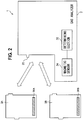
- the gas analysis system 1 of the embodiment can be configured so that, as shown in Fig. 2 , plural types of liquid separators can be attached to the gas analyzer 2.
- a liquid separator 3A for an adult, and a liquid separator 3B for a neonate can be attached to the gas analyzer 2.
- the liquid separator 3A includes a magnet 36A.
- the magnet 36A is disposed in the liquid separator 3A so that, for example, the N pole of the magnet 36A is directed toward the magnetic sensor 24 when the liquid separator 3A is attached to the gas analyzer 2.
- the liquid separator 3B includes a magnet 36B.
- the magnet 36B is disposed in the liquid separator 3B so that, for example, the S pole of the magnet 36B is directed toward the magnetic sensor when the liquid separator 3B is attached to the gas analyzer 2.
- the magnetic sensor 24 of the gas analyzer 2 is configured so as to detect the polarity which is exhibited by a magnet.
- the determining section 25 of the gas analyzer 2 is configured so as to determine the type of the attached liquid separator based on the magnet polarity detected by the magnetic sensor 24. In the example, when the magnetic sensor 24 detects the N pole, the determining section 25 determines that the liquid separator 3A for an adult is attached. When the magnetic sensor 24 detects the S pole, the determining section 25 determines that the liquid separator 3B for a neonate is attached. In other words, the polarity of each of the magnets 36A and 36B indicates the type of the liquid separator to which the magnet itself is attached.
- both the attachment state of the liquid separator 3 with respect to the gas analyzer 2, and the type of the liquid separator can be detected simply by disposing one magnet and one magnetic sensor. The number of components related to the detection is reduced, and therefore the possibility of occurrence of a failure or the like in the detection function can be lowered.
- an inexpensive Hall element can be used as the magnetic sensor 24. Therefore, the cost can be reduced in both the gas analyzer 2 and the liquid separator 3, with the result that the cost of constructing the gas analysis system 1 can be suppressed.
- the gas analyzer 2 can include a pressure sensor 26 and a checking section 27.
- the pressure sensor 26 is configured so as to detect the pressure of the gas flow path 23.
- the checking section 27 is configured so as to check whether the liquid separator 3 is correctly attached or not, based on a change of the pressure detected by the pressure sensor 26.
- the checking section 27 is configured so as to, in the case where such a situation occurs, detect an abnormality in the attachment of the liquid separator 3.
- the analyzing section 21 may be configured so as to, only when the determining section 25 determines that the liquid separator 3 is attached, and the checking section 27 confirms the correct attachment of the liquid separator 3, perform a predetermined analysis.
- the analyzing section 21 may be configured so as to, only when the determining section 25 determines that the liquid separator 3 is attached, and the checking section 27 confirms the correct attachment of the liquid separator 3, perform a predetermined analysis.
- at least one of visual notification, auditory notification, and notification by communication to an external apparatus such as a patient monitor
- the type of the liquid separator 3 i.e. the type for an adult, or that for a neonate is indicated depending on the polarity of the magnet 36 provided in the liquid separator 3.
- the type of the liquid separator 3 which is indicated by the polarity of the magnet 36 is adequately determined in accordance with the specification of the liquid separator 3 that is used in the gas analysis system 1.
- the type of the liquid separator 3 which is indicated by the magnet 36 provided in the liquid separator 3 is classified into two categories respectively corresponding to the possible polarities of the magnet 36. If the magnetic sensor 24 can be configured so as to distinguish magnitudes of the magnetic force in addition to or in place of the polarities, however, the type of the liquid separator 3 may be classified into three or more categories. Also in this case, both the attachment state of the liquid separator 3 with respect to the gas analyzer 2, and the type of the liquid separator can be detected simply by disposing one magnet and one magnetic sensor.
- the water content contained in the respiratory gas of the patient is separated by the liquid separator 3.
- the liquid component to be separated can be separated by the hydrophobic filter 33 of the liquid separator 3
- the gas to be acquired is not limited to the respiratory gas
- the liquid component to be separated is not limited to the water content.
- the embodiment is applied to the analysis in which a gas acquired from the human body is analyzed by the analyzing section 21, the invention may be applied also to an analysis in which a gas acquired from the body of an animal other than a human is analyzed by the analyzing section 21.
Landscapes
- Health & Medical Sciences (AREA)
- Life Sciences & Earth Sciences (AREA)
- Engineering & Computer Science (AREA)
- General Health & Medical Sciences (AREA)
- Animal Behavior & Ethology (AREA)
- Veterinary Medicine (AREA)
- Pulmonology (AREA)
- Biomedical Technology (AREA)
- Heart & Thoracic Surgery (AREA)
- Public Health (AREA)
- Chemical & Material Sciences (AREA)
- Physics & Mathematics (AREA)
- Medical Informatics (AREA)
- Biophysics (AREA)
- Physiology (AREA)
- Molecular Biology (AREA)
- Pathology (AREA)
- Surgery (AREA)
- Chemical Kinetics & Catalysis (AREA)
- Analytical Chemistry (AREA)
- Emergency Medicine (AREA)
- Hematology (AREA)
- Anesthesiology (AREA)
- General Chemical & Material Sciences (AREA)
- Oil, Petroleum & Natural Gas (AREA)
- Thermal Sciences (AREA)
- Investigating Or Analysing Biological Materials (AREA)
- Sampling And Sample Adjustment (AREA)
- Measurement Of The Respiration, Hearing Ability, Form, And Blood Characteristics Of Living Organisms (AREA)
- Investigating Or Analyzing Materials By The Use Of Magnetic Means (AREA)
Abstract
Description
- The present invention relates to a gas analyzer which analyzes a gas acquired from a living body. The invention further relates to a liquid separator which is to be detachably attached to such a gas analyzer, and which separates the liquid component from the gas. The invention still further relates to a gas analysis system which includes the gas analyzer and the liquid separator.
- As an example of a gas analyzer of this type, an apparatus is known which acquires a respiratory gas from a patient under surgery, and which measures the concentration of anesthesia gas contained in the respiratory gas.
- In order to prevent water vapor contained in the respiratory gas from being condensed and entering the interior of the gas analyzer, a liquid separator which is also called a water trap is attached to the gas analyzer. The liquid separator includes a hydrophobic filter. The water content contained in the respiratory gas of the patient is captured by the filter, and blocked from entering the gas analyzer. Such a liquid separator is disclosed, for example, in
US 6,896,713 . - The liquid separator and gas analysis instrument which are disclosed in
US 6,896,713 include electric contacts, respectively. When the electric contacts are contacted with each other, it is detected that the liquid separator is attached to the gas analysis instrument. In the configuration depending on an electrical contact, an error in detection of the attachment state may be possibly caused by a contact failure. - It is an object of the invention to improve the accuracy of detection of an attachment state of a liquid separator with respect to a gas analyzer.
-
- (1) According to an aspect of the invention, a gas analysis system includes a gas analyzer which analyzes a gas acquired from a living body and a liquid separator which is detachably attached to the gas analyzer, and which separates a liquid component from the gas. In the gas analysis system, the liquid separator includes a magnet, and the gas analyzer includes a magnetic sensor which detects magnetism generated by the magnet, and a determining section which, based on the magnetism detected by the magnetic sensor, determines that the liquid separator is attached to the gas analyzer.
According to the configuration (1), the attachment state of the liquid separator with respect to the gas analyzer can be detected in a non-contact manner. Unlike the technique which depends on an electrical contact, therefore, there is no possibility that an error in detection of the attachment state is caused by a contact failure. Consequently, the accuracy of detection of the attachment state of the liquid separator with respect to the gas analyzer can be improved. - (2) According to another aspect of the invention, a liquid separator is to be detachably attached to a gas analyzer that analyzes a gas acquired from a living body, and separates a liquid component from the gas. Further, the liquid separator includes a magnet which generates magnetism that is to be detected by a magnetic sensor provided in the gas analyzer.
- (3) According to another aspect of the invention, a gas analyzer to which a liquid separator separating a liquid component from a gas acquired from a living body is detachably attached includes a magnetic sensor and a determining section. The magnetic sensor detects magnetism generated by a magnet provided in the liquid separator, and the determining section determines that the liquid separator is attached to the gas analyzer based on the magnetism detected by the magnetic sensor.
-
-
Fig. 1 is a diagram showing the functional configuration of a gas analysis system of an embodiment. -
Fig. 2 is a diagram illustrating the operation of the gas analysis system. - Hereinafter, an embodiment will be described in detail with reference to the accompanying drawings.
Fig. 1 shows the functional configuration of a gas analysis system of the embodiment. The gas analysis system 1 includes agas analyzer 2 and a liquid separator 3. - The
gas analyzer 2 includes ananalyzing section 21 and aninterface 22. The liquid separator 3 is configured so as to be attachable to and detachable from theinterface 22 of thegas analyzer 2. The liquid separator 3 is configured so as to separate a liquid component from a gas acquired from a living body. - The liquid separator 3 includes an
introduction port 31. A sampling tube 4 for guiding a respiratory gas (an example of the gas) of a patient (an example of the living body) is detachably connected to theintroduction port 31. - The liquid separator 3 includes a
reservoir 32, ahydrophobic filter 33, and agas passage 34. Theintroduction port 31 is opened in the thereservoir 32. Thehydrophobic filter 33 separates thereservoir 32 and thegas passage 34 from each other. - The liquid separator 3 includes a
discharge port 35. Thedischarge port 35 communicates with thegas passage 34. Thedischarge port 35 is configured so as to be connectable to theinterface 22 of thegas analyzer 2. - The
gas analyzer 2 includes agas flow path 23. The analyzingsection 21 and theinterface 22 communicate with each other via thegas flow path 23. When thedischarge port 35 of the liquid separator 3 is connected to theinterface 22, a flow path extending from the sampling tube 4 which is connected to the patient, to the analyzingsection 21 through the liquid separator 3 is formed. - The
gas analyzer 2 includes a pump and suction interface which are not shown. The pump and the suction interface communicate with each other. On the other hand, the liquid separator 3 includes a suction port which is not shown. The suction port and thegas passage 34 communicate with each other. When the liquid separator 3 is attached to thegas analyzer 2, the suction port is connected to the suction interface. As a result, a gas flow path extending from thegas passage 34 to the pump is formed. - When the pump operates, a gas flow extending from the
introduction port 31 to thedischarge port 35 through thereservoir 32 and thegas passage 34 is produced. The water content (an example of the liquid component) contained in the respiratory gas of the patient which is introduced into the liquid separator 3 through theintroduction port 31 is blocked from passage by thehydrophobic filter 33, and accumulated in thereservoir 32. - The respiratory gas of the patient from which the water content is removed is sucked into the
gas analyzer 2 from thedischarge port 35 connected to theinterface 22. The respiratory gas passes through thegas flow path 23 to reach the analyzingsection 21. The analyzingsection 21 is configured so as to analyze concentrations of carbon dioxide, oxygen, nitrous oxide , a volatile anesthetic agent, and the like which are contained in the respiratory gas. - The liquid separator 3 includes a
magnet 36. Thegas analyzer 2 includes amagnetic sensor 24 and a determiningsection 25. Themagnetic sensor 24 is configured so as to detect magnetism generated by themagnet 36. The determiningsection 25 is configured so as to determine that the liquid separator 3 is attached to thegas analyzer 2, based on the magnetism detected by themagnetic sensor 24. - When the liquid separator 3 is attached to the
gas analyzer 2, themagnet 36 approaches themagnetic sensor 24. This causes the magnitude of the magnetism detected by themagnetic sensor 24, to be increased. For example, the determiningsection 25 can be configured so as to, in the case where the magnitude of the magnetism detected by themagnetic sensor 24 exceeds a threshold, determine that the liquid separator 3 is attached to thegas analyzer 2. - The analyzing
section 21 can be configured so as to perform a predetermined analysis, only in the case where the determiningsection 25 determines that the liquid separator 3 is attached to the gas analyzer. - According to the configuration, the attachment state of the liquid separator 3 with respect to the
gas analyzer 2 can be detected in a non-contact manner. Unlike the technique which depends on an electrical contact, there is no possibility that an error in detection of the attachment state is caused by a contact failure. Consequently, the accuracy of detection of the attachment state of the liquid separator 3 with respect to thegas analyzer 2 can be improved. - The gas analysis system 1 of the embodiment can be configured so that, as shown in
Fig. 2 , plural types of liquid separators can be attached to thegas analyzer 2. For example, aliquid separator 3A for an adult, and aliquid separator 3B for a neonate can be attached to thegas analyzer 2. - The
liquid separator 3A includes amagnet 36A. Themagnet 36A is disposed in theliquid separator 3A so that, for example, the N pole of themagnet 36A is directed toward themagnetic sensor 24 when theliquid separator 3A is attached to thegas analyzer 2. Theliquid separator 3B includes amagnet 36B. Themagnet 36B is disposed in theliquid separator 3B so that, for example, the S pole of themagnet 36B is directed toward the magnetic sensor when theliquid separator 3B is attached to thegas analyzer 2. - In this case, the
magnetic sensor 24 of thegas analyzer 2 is configured so as to detect the polarity which is exhibited by a magnet. The determiningsection 25 of thegas analyzer 2 is configured so as to determine the type of the attached liquid separator based on the magnet polarity detected by themagnetic sensor 24. In the example, when themagnetic sensor 24 detects the N pole, the determiningsection 25 determines that theliquid separator 3A for an adult is attached. When themagnetic sensor 24 detects the S pole, the determiningsection 25 determines that theliquid separator 3B for a neonate is attached. In other words, the polarity of each of themagnets - In a system in which the attachment state of a liquid separator is detected by means of an electrical contact, in the case where also the type of the liquid separator is to be detected, at least one electric contact for detecting the type is necessary in addition to an electric contact for detecting the attachment state. In the configuration of the embodiment, by contrast, both the attachment state of the liquid separator 3 with respect to the
gas analyzer 2, and the type of the liquid separator can be detected simply by disposing one magnet and one magnetic sensor. The number of components related to the detection is reduced, and therefore the possibility of occurrence of a failure or the like in the detection function can be lowered. - In the case where it is necessary to detect only the polarity of the magnet, an inexpensive Hall element can be used as the
magnetic sensor 24. Therefore, the cost can be reduced in both thegas analyzer 2 and the liquid separator 3, with the result that the cost of constructing the gas analysis system 1 can be suppressed. - As shown in
Fig. 1 , thegas analyzer 2 can include apressure sensor 26 and achecking section 27. Thepressure sensor 26 is configured so as to detect the pressure of thegas flow path 23. The checkingsection 27 is configured so as to check whether the liquid separator 3 is correctly attached or not, based on a change of the pressure detected by thepressure sensor 26. - In the case where the
discharge port 35 of the liquid separator 3 is not correctly connected to theinterface 22 of thegas analyzer 2, even when the pump operates, for example, the pressure of thegas flow path 23 does not show a predetermined change. The checkingsection 27 is configured so as to, in the case where such a situation occurs, detect an abnormality in the attachment of the liquid separator 3. - According to the configuration, while a non-contact detection system is employed, it is possible to detect more surely that the liquid separator 3 is correctly attached to the
gas analyzer 2. That is, the accuracy of detection of the attachment state of the liquid separator 3 with respect to thegas analyzer 2 can be further improved. - For example, the analyzing
section 21 may be configured so as to, only when the determiningsection 25 determines that the liquid separator 3 is attached, and thechecking section 27 confirms the correct attachment of the liquid separator 3, perform a predetermined analysis. In the case where an abnormality in the attachment of the liquid separator 3 is detected, at least one of visual notification, auditory notification, and notification by communication to an external apparatus (such as a patient monitor) may be performed. - The above-described embodiment is a mere example for facilitating understanding of the invention. The configuration of the embodiment may be adequately changed or improved without departing the spirit of the invention. It is obvious that equivalents are included within the technical scope of the invention.
- In the embodiment, the type of the liquid separator 3, i.e. the type for an adult, or that for a neonate is indicated depending on the polarity of the
magnet 36 provided in the liquid separator 3. However, the type of the liquid separator 3 which is indicated by the polarity of themagnet 36 is adequately determined in accordance with the specification of the liquid separator 3 that is used in the gas analysis system 1. - In the embodiment, the type of the liquid separator 3 which is indicated by the
magnet 36 provided in the liquid separator 3 is classified into two categories respectively corresponding to the possible polarities of themagnet 36. If themagnetic sensor 24 can be configured so as to distinguish magnitudes of the magnetic force in addition to or in place of the polarities, however, the type of the liquid separator 3 may be classified into three or more categories. Also in this case, both the attachment state of the liquid separator 3 with respect to thegas analyzer 2, and the type of the liquid separator can be detected simply by disposing one magnet and one magnetic sensor. - In the embodiment, the water content contained in the respiratory gas of the patient is separated by the liquid separator 3. As far as the liquid component to be separated can be separated by the
hydrophobic filter 33 of the liquid separator 3, the gas to be acquired is not limited to the respiratory gas, and the liquid component to be separated is not limited to the water content. - Although the embodiment is applied to the analysis in which a gas acquired from the human body is analyzed by the analyzing
section 21, the invention may be applied also to an analysis in which a gas acquired from the body of an animal other than a human is analyzed by the analyzingsection 21.
Claims (14)
- A gas analysis system comprising:a gas analyzer which analyzes a gas acquired from a living body; anda liquid separator which is detachably attached to the gas analyzer, and which separates a liquid component from the gas, whereinthe liquid separator includes a magnet, andthe gas analyzer includes:a magnetic sensor which detects magnetism generated by the magnet; anda determining section which, based on the magnetism detected by the magnetic sensor, determines that the liquid separator is attached to the gas analyzer.
- The gas analysis system according to claim 1, wherein
the magnet is configured to indicates a type of the liquid separator, and
the determining section determines the type based on the magnetism detected by the magnetic sensor. - The gas analysis system according to claim 2, wherein
the magnetic sensor includes a Hall element which detects a polarity of the magnet. - The gas analysis system according to claim 2 or 3, wherein
the type includes a type for an adult and a type for a neonate. - The gas analysis system according to any one of claims 1 to 4, wherein
the gas analyzer further includes:a pressure sensor that detects a pressure of a flow path through which the gas flows; anda checking section that checks whether the liquid separator is correctly attached or not, based on a change of the pressure detected by the pressure sensor. - A liquid separator which is to be detachably attached to a gas analyzer that analyzes a gas acquired from a living body, and which separates a liquid component from the gas, wherein
the liquid separator includes a magnet which generates magnetism that is to be detected by a magnetic sensor provided in the gas analyzer. - The liquid separator according to claim 6, wherein
the magnetism is set to indicate a type of the liquid separator itself. - The liquid separator according to claim 7, wherein
a polarity of the magnet is set to indicate the type. - The liquid separator according to claim 7 or 8, wherein
the type includes a type for an adult and a type for a neonate. - A gas analyzer to which a liquid separator is to be detachably attached, the liquid separator separating a liquid component from a gas acquired from a living body, wherein
the gas analyzer includes:a magnetic sensor which detects magnetism generated by a magnet provided in the liquid separator; anda determining section which, based on the magnetism detected by the magnetic sensor, determines that the liquid separator is attached to the gas analyzer. - The gas analyzer according to claim 10, wherein
the determining section determines a type of the liquid separator based on the magnetism detected by the magnetic sensor. - The gas analyzer according to claim 11, wherein
the magnetic sensor is a Hall element which detects a polarity that is exhibited by the magnet. - The gas analyzer according to claim 11 or 12, wherein
the type includes a type for an adult and a type for a neonate. - The gas analyzer according to any one of claims 10 to 13, wherein
the gas analyzer further includes:a pressure sensor that detects a pressure of a gas flow path through which the gas flows; anda checking section that checks whether the liquid separator is correctly attached or not, based on a change of the pressure detected by the pressure sensor.
Applications Claiming Priority (1)
| Application Number | Priority Date | Filing Date | Title |
|---|---|---|---|
| JP2016120195A JP6973993B2 (en) | 2016-06-16 | 2016-06-16 | Gas analyzers, liquid separators, and gas analyzers |
Publications (2)
| Publication Number | Publication Date |
|---|---|
| EP3257440A1 true EP3257440A1 (en) | 2017-12-20 |
| EP3257440B1 EP3257440B1 (en) | 2020-11-04 |
Family
ID=59030805
Family Applications (1)
| Application Number | Title | Priority Date | Filing Date |
|---|---|---|---|
| EP17174715.7A Active EP3257440B1 (en) | 2016-06-16 | 2017-06-07 | Gas analysis system, liquid separator, and gas analyzer |
Country Status (3)
| Country | Link |
|---|---|
| US (1) | US10376830B2 (en) |
| EP (1) | EP3257440B1 (en) |
| JP (1) | JP6973993B2 (en) |
Families Citing this family (1)
| Publication number | Priority date | Publication date | Assignee | Title |
|---|---|---|---|---|
| KR102239294B1 (en) * | 2019-03-28 | 2021-04-12 | 한국기계연구원 | System for measuring concentration of propofol and method for measuring the concentration of propofol using the same |
Citations (4)
| Publication number | Priority date | Publication date | Assignee | Title |
|---|---|---|---|---|
| US20030191405A1 (en) * | 2002-04-04 | 2003-10-09 | Ric Investments, Inc. | Sidestream gas sampling system with detachable sample cell |
| US6896713B1 (en) | 1999-02-02 | 2005-05-24 | Artema Medical Ab | Liquid separator with holder unit |
| WO2013070545A1 (en) * | 2011-11-07 | 2013-05-16 | Landy Toth | Metabolic and cardiopulmonary monitor |
| WO2014068000A1 (en) * | 2012-10-31 | 2014-05-08 | Maquet Critical Care Ab | A Breathing Apparatus and a Method therein |
Family Cites Families (14)
| Publication number | Priority date | Publication date | Assignee | Title |
|---|---|---|---|---|
| US3698159A (en) * | 1968-09-11 | 1972-10-17 | Hartmann & Braun Ag | Gas analyzer and mist separator |
| JPS5754859A (en) * | 1980-09-19 | 1982-04-01 | Hitachi Ltd | Gas analyzer |
| US4997463A (en) * | 1988-10-07 | 1991-03-05 | Frederick William Ricciardelli | Gas-liquid microvolume separating apparatus and method |
| JP3154078B2 (en) * | 1993-10-27 | 2001-04-09 | 日本光電工業株式会社 | Gas-liquid separator for respiratory gas analyzer |
| US6550347B2 (en) * | 2000-11-30 | 2003-04-22 | Bruce J. Bradley | Vacuum air component sampler |
| JP2004254139A (en) * | 2003-02-20 | 2004-09-09 | Nec Access Technica Ltd | Mobile terminal with camera |
| JP2010062969A (en) * | 2008-09-05 | 2010-03-18 | Rohm Co Ltd | Electronic apparatus, and removable unit |
| SE532941C2 (en) * | 2008-09-15 | 2010-05-18 | Phasein Ab | Gas sampling line for breathing gases |
| US8181648B2 (en) * | 2008-09-26 | 2012-05-22 | Nellcor Puritan Bennett Llc | Systems and methods for managing pressure in a breathing assistance system |
| US8302602B2 (en) * | 2008-09-30 | 2012-11-06 | Nellcor Puritan Bennett Llc | Breathing assistance system with multiple pressure sensors |
| JP2010223641A (en) * | 2009-03-20 | 2010-10-07 | Horiba Ltd | Fluorescent x-ray analyzer |
| JP5206997B2 (en) * | 2010-01-28 | 2013-06-12 | 日本光電工業株式会社 | Gas analyzer |
| CN105080285A (en) * | 2010-02-22 | 2015-11-25 | 克里蒂凯尔系统公司 | Inline water trap |
| EP2466306A1 (en) * | 2010-12-17 | 2012-06-20 | General Electric Company | Holder for a liquid separator and gas analyzer for analyzing respiratory gas samples |
-
2016
- 2016-06-16 JP JP2016120195A patent/JP6973993B2/en active Active
-
2017
- 2017-06-06 US US15/614,709 patent/US10376830B2/en active Active
- 2017-06-07 EP EP17174715.7A patent/EP3257440B1/en active Active
Patent Citations (4)
| Publication number | Priority date | Publication date | Assignee | Title |
|---|---|---|---|---|
| US6896713B1 (en) | 1999-02-02 | 2005-05-24 | Artema Medical Ab | Liquid separator with holder unit |
| US20030191405A1 (en) * | 2002-04-04 | 2003-10-09 | Ric Investments, Inc. | Sidestream gas sampling system with detachable sample cell |
| WO2013070545A1 (en) * | 2011-11-07 | 2013-05-16 | Landy Toth | Metabolic and cardiopulmonary monitor |
| WO2014068000A1 (en) * | 2012-10-31 | 2014-05-08 | Maquet Critical Care Ab | A Breathing Apparatus and a Method therein |
Also Published As
| Publication number | Publication date |
|---|---|
| JP6973993B2 (en) | 2021-12-01 |
| EP3257440B1 (en) | 2020-11-04 |
| US20170361269A1 (en) | 2017-12-21 |
| JP2017221514A (en) | 2017-12-21 |
| US10376830B2 (en) | 2019-08-13 |
Similar Documents
| Publication | Publication Date | Title |
|---|---|---|
| GB2552842B (en) | Aspirators | |
| US20210085213A1 (en) | Cannabis drug detection device | |
| US9974916B2 (en) | Sidestream respiratory gas sampling system with flexible accessories and removable water trap | |
| EP3177923B1 (en) | Removable tamper-resistant breath alcohol sampling system | |
| EP2914321B1 (en) | A breathing apparatus and a method therein | |
| US20190142303A1 (en) | Breath analysis systems and methods for screening infectious diseases | |
| CA2606883A1 (en) | Vehicle ignition interlock systems with mouth alcohol contamination sensor | |
| WO2009030957A1 (en) | Apparatus and method | |
| KR20160047565A (en) | Universal breath analysis sampling device | |
| US20100313887A1 (en) | Method for operating a rebreather | |
| CN108348715B (en) | Ventilator | |
| US10376830B2 (en) | Gas analysis system, liquid separator, and gas analyzer | |
| US8992430B2 (en) | Breath sampling system | |
| US5394881A (en) | Liquid ingress control for a gas monitor | |
| WO2023178454A1 (en) | Contact-free breath analysis device and method | |
| JP7189011B2 (en) | Exhaled gas detection device | |
| EP2466306A1 (en) | Holder for a liquid separator and gas analyzer for analyzing respiratory gas samples | |
| EP2363065A1 (en) | Gas analyzer | |
| EP1584345B1 (en) | Arrangement for analysing respiratory gases | |
| KR101057148B1 (en) | Portable blood analysis device | |
| KR20180103834A (en) | Personal gas monitor diagnostic system and method | |
| CN219699923U (en) | Side-stream end-of-call carbon dioxide detection device | |
| CN105168240B (en) | For treating the gaseous medication containing NO and delivery system of people's pulmonary hypertension | |
| JP2016138808A (en) | Gas chromatograph | |
| ZA202307817B (en) | Sensing system, method and device for non-invasively detecting chronic kidney disease from exhaled breath |
Legal Events
| Date | Code | Title | Description |
|---|---|---|---|
| PUAI | Public reference made under article 153(3) epc to a published international application that has entered the european phase |
Free format text: ORIGINAL CODE: 0009012 |
|
| STAA | Information on the status of an ep patent application or granted ep patent |
Free format text: STATUS: THE APPLICATION HAS BEEN PUBLISHED |
|
| AK | Designated contracting states |
Kind code of ref document: A1 Designated state(s): AL AT BE BG CH CY CZ DE DK EE ES FI FR GB GR HR HU IE IS IT LI LT LU LV MC MK MT NL NO PL PT RO RS SE SI SK SM TR |
|
| AX | Request for extension of the european patent |
Extension state: BA ME |
|
| STAA | Information on the status of an ep patent application or granted ep patent |
Free format text: STATUS: REQUEST FOR EXAMINATION WAS MADE |
|
| 17P | Request for examination filed |
Effective date: 20180606 |
|
| RBV | Designated contracting states (corrected) |
Designated state(s): AL AT BE BG CH CY CZ DE DK EE ES FI FR GB GR HR HU IE IS IT LI LT LU LV MC MK MT NL NO PL PT RO RS SE SI SK SM TR |
|
| STAA | Information on the status of an ep patent application or granted ep patent |
Free format text: STATUS: EXAMINATION IS IN PROGRESS |
|
| 17Q | First examination report despatched |
Effective date: 20190201 |
|
| GRAP | Despatch of communication of intention to grant a patent |
Free format text: ORIGINAL CODE: EPIDOSNIGR1 |
|
| STAA | Information on the status of an ep patent application or granted ep patent |
Free format text: STATUS: GRANT OF PATENT IS INTENDED |
|
| RIC1 | Information provided on ipc code assigned before grant |
Ipc: A61B 5/05 20060101ALN20200514BHEP Ipc: A61B 5/08 20060101AFI20200514BHEP Ipc: A61M 16/08 20060101ALN20200514BHEP |
|
| INTG | Intention to grant announced |
Effective date: 20200528 |
|
| GRAS | Grant fee paid |
Free format text: ORIGINAL CODE: EPIDOSNIGR3 |
|
| GRAA | (expected) grant |
Free format text: ORIGINAL CODE: 0009210 |
|
| STAA | Information on the status of an ep patent application or granted ep patent |
Free format text: STATUS: THE PATENT HAS BEEN GRANTED |
|
| AK | Designated contracting states |
Kind code of ref document: B1 Designated state(s): AL AT BE BG CH CY CZ DE DK EE ES FI FR GB GR HR HU IE IS IT LI LT LU LV MC MK MT NL NO PL PT RO RS SE SI SK SM TR |
|
| REG | Reference to a national code |
Ref country code: GB Ref legal event code: FG4D |
|
| REG | Reference to a national code |
Ref country code: CH Ref legal event code: EP |
|
| REG | Reference to a national code |
Ref country code: AT Ref legal event code: REF Ref document number: 1329763 Country of ref document: AT Kind code of ref document: T Effective date: 20201115 |
|
| REG | Reference to a national code |
Ref country code: IE Ref legal event code: FG4D |
|
| REG | Reference to a national code |
Ref country code: DE Ref legal event code: R096 Ref document number: 602017026650 Country of ref document: DE |
|
| REG | Reference to a national code |
Ref country code: NL Ref legal event code: MP Effective date: 20201104 |
|
| REG | Reference to a national code |
Ref country code: AT Ref legal event code: MK05 Ref document number: 1329763 Country of ref document: AT Kind code of ref document: T Effective date: 20201104 |
|
| PG25 | Lapsed in a contracting state [announced via postgrant information from national office to epo] |
Ref country code: RS Free format text: LAPSE BECAUSE OF FAILURE TO SUBMIT A TRANSLATION OF THE DESCRIPTION OR TO PAY THE FEE WITHIN THE PRESCRIBED TIME-LIMIT Effective date: 20201104 Ref country code: PT Free format text: LAPSE BECAUSE OF FAILURE TO SUBMIT A TRANSLATION OF THE DESCRIPTION OR TO PAY THE FEE WITHIN THE PRESCRIBED TIME-LIMIT Effective date: 20210304 Ref country code: NO Free format text: LAPSE BECAUSE OF FAILURE TO SUBMIT A TRANSLATION OF THE DESCRIPTION OR TO PAY THE FEE WITHIN THE PRESCRIBED TIME-LIMIT Effective date: 20210204 Ref country code: FI Free format text: LAPSE BECAUSE OF FAILURE TO SUBMIT A TRANSLATION OF THE DESCRIPTION OR TO PAY THE FEE WITHIN THE PRESCRIBED TIME-LIMIT Effective date: 20201104 Ref country code: GR Free format text: LAPSE BECAUSE OF FAILURE TO SUBMIT A TRANSLATION OF THE DESCRIPTION OR TO PAY THE FEE WITHIN THE PRESCRIBED TIME-LIMIT Effective date: 20210205 |
|
| PG25 | Lapsed in a contracting state [announced via postgrant information from national office to epo] |
Ref country code: SE Free format text: LAPSE BECAUSE OF FAILURE TO SUBMIT A TRANSLATION OF THE DESCRIPTION OR TO PAY THE FEE WITHIN THE PRESCRIBED TIME-LIMIT Effective date: 20201104 Ref country code: BG Free format text: LAPSE BECAUSE OF FAILURE TO SUBMIT A TRANSLATION OF THE DESCRIPTION OR TO PAY THE FEE WITHIN THE PRESCRIBED TIME-LIMIT Effective date: 20210204 Ref country code: LV Free format text: LAPSE BECAUSE OF FAILURE TO SUBMIT A TRANSLATION OF THE DESCRIPTION OR TO PAY THE FEE WITHIN THE PRESCRIBED TIME-LIMIT Effective date: 20201104 Ref country code: IS Free format text: LAPSE BECAUSE OF FAILURE TO SUBMIT A TRANSLATION OF THE DESCRIPTION OR TO PAY THE FEE WITHIN THE PRESCRIBED TIME-LIMIT Effective date: 20210304 Ref country code: PL Free format text: LAPSE BECAUSE OF FAILURE TO SUBMIT A TRANSLATION OF THE DESCRIPTION OR TO PAY THE FEE WITHIN THE PRESCRIBED TIME-LIMIT Effective date: 20201104 Ref country code: AT Free format text: LAPSE BECAUSE OF FAILURE TO SUBMIT A TRANSLATION OF THE DESCRIPTION OR TO PAY THE FEE WITHIN THE PRESCRIBED TIME-LIMIT Effective date: 20201104 Ref country code: ES Free format text: LAPSE BECAUSE OF FAILURE TO SUBMIT A TRANSLATION OF THE DESCRIPTION OR TO PAY THE FEE WITHIN THE PRESCRIBED TIME-LIMIT Effective date: 20201104 |
|
| REG | Reference to a national code |
Ref country code: LT Ref legal event code: MG9D |
|
| PG25 | Lapsed in a contracting state [announced via postgrant information from national office to epo] |
Ref country code: HR Free format text: LAPSE BECAUSE OF FAILURE TO SUBMIT A TRANSLATION OF THE DESCRIPTION OR TO PAY THE FEE WITHIN THE PRESCRIBED TIME-LIMIT Effective date: 20201104 |
|
| PG25 | Lapsed in a contracting state [announced via postgrant information from national office to epo] |
Ref country code: SK Free format text: LAPSE BECAUSE OF FAILURE TO SUBMIT A TRANSLATION OF THE DESCRIPTION OR TO PAY THE FEE WITHIN THE PRESCRIBED TIME-LIMIT Effective date: 20201104 Ref country code: RO Free format text: LAPSE BECAUSE OF FAILURE TO SUBMIT A TRANSLATION OF THE DESCRIPTION OR TO PAY THE FEE WITHIN THE PRESCRIBED TIME-LIMIT Effective date: 20201104 Ref country code: EE Free format text: LAPSE BECAUSE OF FAILURE TO SUBMIT A TRANSLATION OF THE DESCRIPTION OR TO PAY THE FEE WITHIN THE PRESCRIBED TIME-LIMIT Effective date: 20201104 Ref country code: CZ Free format text: LAPSE BECAUSE OF FAILURE TO SUBMIT A TRANSLATION OF THE DESCRIPTION OR TO PAY THE FEE WITHIN THE PRESCRIBED TIME-LIMIT Effective date: 20201104 Ref country code: SM Free format text: LAPSE BECAUSE OF FAILURE TO SUBMIT A TRANSLATION OF THE DESCRIPTION OR TO PAY THE FEE WITHIN THE PRESCRIBED TIME-LIMIT Effective date: 20201104 Ref country code: LT Free format text: LAPSE BECAUSE OF FAILURE TO SUBMIT A TRANSLATION OF THE DESCRIPTION OR TO PAY THE FEE WITHIN THE PRESCRIBED TIME-LIMIT Effective date: 20201104 |
|
| REG | Reference to a national code |
Ref country code: DE Ref legal event code: R097 Ref document number: 602017026650 Country of ref document: DE |
|
| PG25 | Lapsed in a contracting state [announced via postgrant information from national office to epo] |
Ref country code: DK Free format text: LAPSE BECAUSE OF FAILURE TO SUBMIT A TRANSLATION OF THE DESCRIPTION OR TO PAY THE FEE WITHIN THE PRESCRIBED TIME-LIMIT Effective date: 20201104 |
|
| PLBE | No opposition filed within time limit |
Free format text: ORIGINAL CODE: 0009261 |
|
| STAA | Information on the status of an ep patent application or granted ep patent |
Free format text: STATUS: NO OPPOSITION FILED WITHIN TIME LIMIT |
|
| 26N | No opposition filed |
Effective date: 20210805 |
|
| PG25 | Lapsed in a contracting state [announced via postgrant information from national office to epo] |
Ref country code: AL Free format text: LAPSE BECAUSE OF FAILURE TO SUBMIT A TRANSLATION OF THE DESCRIPTION OR TO PAY THE FEE WITHIN THE PRESCRIBED TIME-LIMIT Effective date: 20201104 Ref country code: NL Free format text: LAPSE BECAUSE OF FAILURE TO SUBMIT A TRANSLATION OF THE DESCRIPTION OR TO PAY THE FEE WITHIN THE PRESCRIBED TIME-LIMIT Effective date: 20201104 Ref country code: IT Free format text: LAPSE BECAUSE OF FAILURE TO SUBMIT A TRANSLATION OF THE DESCRIPTION OR TO PAY THE FEE WITHIN THE PRESCRIBED TIME-LIMIT Effective date: 20201104 |
|
| PG25 | Lapsed in a contracting state [announced via postgrant information from national office to epo] |
Ref country code: SI Free format text: LAPSE BECAUSE OF FAILURE TO SUBMIT A TRANSLATION OF THE DESCRIPTION OR TO PAY THE FEE WITHIN THE PRESCRIBED TIME-LIMIT Effective date: 20201104 |
|
| PG25 | Lapsed in a contracting state [announced via postgrant information from national office to epo] |
Ref country code: MC Free format text: LAPSE BECAUSE OF FAILURE TO SUBMIT A TRANSLATION OF THE DESCRIPTION OR TO PAY THE FEE WITHIN THE PRESCRIBED TIME-LIMIT Effective date: 20201104 |
|
| REG | Reference to a national code |
Ref country code: CH Ref legal event code: PL |
|
| GBPC | Gb: european patent ceased through non-payment of renewal fee |
Effective date: 20210607 |
|
| REG | Reference to a national code |
Ref country code: BE Ref legal event code: MM Effective date: 20210630 |
|
| PG25 | Lapsed in a contracting state [announced via postgrant information from national office to epo] |
Ref country code: LU Free format text: LAPSE BECAUSE OF NON-PAYMENT OF DUE FEES Effective date: 20210607 |
|
| PG25 | Lapsed in a contracting state [announced via postgrant information from national office to epo] |
Ref country code: LI Free format text: LAPSE BECAUSE OF NON-PAYMENT OF DUE FEES Effective date: 20210630 Ref country code: IE Free format text: LAPSE BECAUSE OF NON-PAYMENT OF DUE FEES Effective date: 20210607 Ref country code: GB Free format text: LAPSE BECAUSE OF NON-PAYMENT OF DUE FEES Effective date: 20210607 Ref country code: CH Free format text: LAPSE BECAUSE OF NON-PAYMENT OF DUE FEES Effective date: 20210630 |
|
| PG25 | Lapsed in a contracting state [announced via postgrant information from national office to epo] |
Ref country code: IS Free format text: LAPSE BECAUSE OF FAILURE TO SUBMIT A TRANSLATION OF THE DESCRIPTION OR TO PAY THE FEE WITHIN THE PRESCRIBED TIME-LIMIT Effective date: 20210304 Ref country code: FR Free format text: LAPSE BECAUSE OF NON-PAYMENT OF DUE FEES Effective date: 20210630 |
|
| PG25 | Lapsed in a contracting state [announced via postgrant information from national office to epo] |
Ref country code: BE Free format text: LAPSE BECAUSE OF NON-PAYMENT OF DUE FEES Effective date: 20210630 |
|
| PG25 | Lapsed in a contracting state [announced via postgrant information from national office to epo] |
Ref country code: HU Free format text: LAPSE BECAUSE OF FAILURE TO SUBMIT A TRANSLATION OF THE DESCRIPTION OR TO PAY THE FEE WITHIN THE PRESCRIBED TIME-LIMIT; INVALID AB INITIO Effective date: 20170607 |
|
| PG25 | Lapsed in a contracting state [announced via postgrant information from national office to epo] |
Ref country code: CY Free format text: LAPSE BECAUSE OF FAILURE TO SUBMIT A TRANSLATION OF THE DESCRIPTION OR TO PAY THE FEE WITHIN THE PRESCRIBED TIME-LIMIT Effective date: 20201104 |
|
| PG25 | Lapsed in a contracting state [announced via postgrant information from national office to epo] |
Ref country code: MK Free format text: LAPSE BECAUSE OF FAILURE TO SUBMIT A TRANSLATION OF THE DESCRIPTION OR TO PAY THE FEE WITHIN THE PRESCRIBED TIME-LIMIT Effective date: 20201104 |
|
| PG25 | Lapsed in a contracting state [announced via postgrant information from national office to epo] |
Ref country code: MT Free format text: LAPSE BECAUSE OF FAILURE TO SUBMIT A TRANSLATION OF THE DESCRIPTION OR TO PAY THE FEE WITHIN THE PRESCRIBED TIME-LIMIT Effective date: 20201104 |
|
| PGFP | Annual fee paid to national office [announced via postgrant information from national office to epo] |
Ref country code: DE Payment date: 20250429 Year of fee payment: 9 |
|
| PG25 | Lapsed in a contracting state [announced via postgrant information from national office to epo] |
Ref country code: TR Free format text: LAPSE BECAUSE OF FAILURE TO SUBMIT A TRANSLATION OF THE DESCRIPTION OR TO PAY THE FEE WITHIN THE PRESCRIBED TIME-LIMIT Effective date: 20201104 |