EP3257386A1 - Smoke generator and assembling method therefor - Google Patents
Smoke generator and assembling method therefor Download PDFInfo
- Publication number
- EP3257386A1 EP3257386A1 EP15881702.3A EP15881702A EP3257386A1 EP 3257386 A1 EP3257386 A1 EP 3257386A1 EP 15881702 A EP15881702 A EP 15881702A EP 3257386 A1 EP3257386 A1 EP 3257386A1
- Authority
- EP
- European Patent Office
- Prior art keywords
- support
- onto
- heating bodies
- assembling
- supporting pipe
- Prior art date
- Legal status (The legal status is an assumption and is not a legal conclusion. Google has not performed a legal analysis and makes no representation as to the accuracy of the status listed.)
- Granted
Links
Images



Classifications
-
- A—HUMAN NECESSITIES
- A24—TOBACCO; CIGARS; CIGARETTES; SIMULATED SMOKING DEVICES; SMOKERS' REQUISITES
- A24F—SMOKERS' REQUISITES; MATCH BOXES; SIMULATED SMOKING DEVICES
- A24F40/00—Electrically operated smoking devices; Component parts thereof; Manufacture thereof; Maintenance or testing thereof; Charging means specially adapted therefor
- A24F40/40—Constructional details, e.g. connection of cartridges and battery parts
- A24F40/46—Shape or structure of electric heating means
-
- A—HUMAN NECESSITIES
- A24—TOBACCO; CIGARS; CIGARETTES; SIMULATED SMOKING DEVICES; SMOKERS' REQUISITES
- A24F—SMOKERS' REQUISITES; MATCH BOXES; SIMULATED SMOKING DEVICES
- A24F40/00—Electrically operated smoking devices; Component parts thereof; Manufacture thereof; Maintenance or testing thereof; Charging means specially adapted therefor
- A24F40/40—Constructional details, e.g. connection of cartridges and battery parts
-
- A—HUMAN NECESSITIES
- A24—TOBACCO; CIGARS; CIGARETTES; SIMULATED SMOKING DEVICES; SMOKERS' REQUISITES
- A24F—SMOKERS' REQUISITES; MATCH BOXES; SIMULATED SMOKING DEVICES
- A24F40/00—Electrically operated smoking devices; Component parts thereof; Manufacture thereof; Maintenance or testing thereof; Charging means specially adapted therefor
- A24F40/70—Manufacture
-
- A—HUMAN NECESSITIES
- A61—MEDICAL OR VETERINARY SCIENCE; HYGIENE
- A61M—DEVICES FOR INTRODUCING MEDIA INTO, OR ONTO, THE BODY; DEVICES FOR TRANSDUCING BODY MEDIA OR FOR TAKING MEDIA FROM THE BODY; DEVICES FOR PRODUCING OR ENDING SLEEP OR STUPOR
- A61M11/00—Sprayers or atomisers specially adapted for therapeutic purposes
- A61M11/04—Sprayers or atomisers specially adapted for therapeutic purposes operated by the vapour pressure of the liquid to be sprayed or atomised
- A61M11/041—Sprayers or atomisers specially adapted for therapeutic purposes operated by the vapour pressure of the liquid to be sprayed or atomised using heaters
- A61M11/042—Sprayers or atomisers specially adapted for therapeutic purposes operated by the vapour pressure of the liquid to be sprayed or atomised using heaters electrical
-
- A—HUMAN NECESSITIES
- A61—MEDICAL OR VETERINARY SCIENCE; HYGIENE
- A61M—DEVICES FOR INTRODUCING MEDIA INTO, OR ONTO, THE BODY; DEVICES FOR TRANSDUCING BODY MEDIA OR FOR TAKING MEDIA FROM THE BODY; DEVICES FOR PRODUCING OR ENDING SLEEP OR STUPOR
- A61M15/00—Inhalators
- A61M15/06—Inhaling appliances shaped like cigars, cigarettes or pipes
-
- A—HUMAN NECESSITIES
- A24—TOBACCO; CIGARS; CIGARETTES; SIMULATED SMOKING DEVICES; SMOKERS' REQUISITES
- A24F—SMOKERS' REQUISITES; MATCH BOXES; SIMULATED SMOKING DEVICES
- A24F40/00—Electrically operated smoking devices; Component parts thereof; Manufacture thereof; Maintenance or testing thereof; Charging means specially adapted therefor
- A24F40/20—Devices using solid inhalable precursors
Definitions
- Smoking is not only harmful to health of smokers, but also pollutes surrounding environments.
- a suction device for heating tobacco to produce smoke by a means of non-burning is developed at now.
- the suction device can greatly reduce harmful substances (e.g., tar) that are sucked into human bodies by roasting solid tobacco at a lower temperature.
- harmful substances e.g., tar
- the novel suction device as a novel smoking device, is gradually popular for cigarette consumers.
- heating structures in the interior of most novel cigarette smoking devices are not reasonably arranged.
- the objective of the invention is to provide a smoke generator and assembling method for the smoke generator.
- the individual heating bodies in said smoke generator are independent of each other, and thus when one heating body is in failure, it can be replaced or repaired separately.
- Said assembling method has the advantages of simple and rapid process, high production efficiency and low reject ratio of finished products.
- the smoke generator as involved in the invention is adapted to heat solid smoking materials (e.g., to heat solid tobacco materials) by the means of electric heating, to produce smoke for human suctions.
- the solid smoking materials may be either tobacco materials in a powder form or a particulate form, or tobacco articles that are processed to have a constant shape.
- a gas stream flows into the cavity 11 through the gas inlet, and then it is discharged from the cavity 11 via the gas outlet 21.
- the supporting pipe 10 is made of metallic materials, and the heating bodies 60 are insulated from the supporting pipe 10.
- a plurality of through-holes 12 for gas entrance are disposed on the side of the supporting pipe 10, and the through hole 12 passes through the cavity 11.
- the assembling rod 91 is a part of an assembling tool, and the assembling tool comprises a substrate 92 and an assembling rod 91 disposed on the substrate 92.
- the second end 64 of each heating body 60 of the smoke generator 100 is divided into a first pin 61 and a second pin 62 that are adaptable for electrical connection to the electrodes of the external supply powder source, and the smoke generator 100 further comprises a non-conductive fastener 50 that is fastened in the gas inlet 31, and a base 40 that is engaged or sleeved onto the fastener 50.
- the first pin 61 of the second end 64 of each heating body 60 after being bent, is positioned in the position portion of the second support 30, and the plurality of the first pins 61 are brought into contact with each other, and the individual second pins 62 are intermittently fixed between the fastener 50 and the base 40.
- the heating bodies 60 are in a sheet form, and the number of the heating bodies 60 may be set to be more than three.
- the method for assembling the plurality of heating bodies may be conducted as follows: first of all, according to the step c), the heating bodies are assembled onto the supporting pipe 10 one by one; thereafter, according to the step d), each of the first ends 63 of the plurality of heating bodies 60 is bent and positioned onto the positioning portions, and then each of the first pins 61 of the second end 64 is bent and positioned on the positioning portions.
- the fastener 50 is used to fix the first pin 61 on each of the heating bodies 60 and to separate the first pins 61 from the second pins 62 to prevent false conductions.
- the base is used to intermittently fix the second pin of each heating body between the fastener and the base.
- the positioning portion of the first support 20 or the second support 30 is a groove that is adapted to contain the bent first end 63 or bent second end 64 of the heating bodies 60.
- the positioning portion on the first end 63 is a first groove 22, and the positioning portion of the second end 64 is the second groove 32.
- the smoke generator 100 further comprises a fixing cap 70 that engages the first support 20, and the method for assembling the smoke generator further comprises the step:
- a third aspect of the invention is concerned with a further method of assembling a smoke generator, wherein the smoke generator 100 comprises: a supporting pipe 10, a plurality of heating bodies 60 having a first end 63 and a second end 64 that are disposed in the supporting pipe 10, a first support 20 having an gas outlet 21 and a second support 30 having a gas inlet 31, the first support 20 and the second support 30 being respectively disposed at the two ends of the supporting pipe 10, and a plurality of positioning portions being disposed onto the first support 20 and the second support 30, wherein the first end 63 of each of the plurality of heating bodies 60 is disposed onto the first support 20 and bent onto the positioning portions of the first support 20, and the second end 64 of each of the plurality of heating bodies 60 is disposed on the second support 30 and bent onto the positioning portions of the second support 30; and the plurality of heating bodies 60 surrounds a cavity 11 that is adapted to be filled with smoking materials, wherein the smoke generator 100 further comprises a fixing cap 70 that engages the first support 20, comprising the steps of:
- the fixing cap 70 may be sleeved onto the assembling rod 91, and then the step b) is completed.
- the steps of detaching the supporting pipe 10 on which the plurality of heating bodies 60 have been arranged, and further sleeving the supporting pipe 10 after the fixing cap 70 is sleeved onto the assembling rod 91, are omitted (as shown in Figure 6 , when the heating bodies 60 are assembled, the fixing cap 70 has been sleeved onto the assembling rod 91).
- the assembling rod 91 is a part of an assembling tool, and the assembling tool comprises a substrate 92 and an assembling rod 91 disposed on the substrate 92.
- the second ends 64 of the individual heating bodies 60 of the smoke generator 100 are divided into a first pin 61 and second pin 62 that are adaptable for electrical connection to the electrodes of external supply powder source, and the smoke generator 100 further comprises a non-conductive fastener 50 that is fastened in the gas inlet 31, and a base 40 that is engaged or sleeved onto the fastener 50.
- the first pins 61 of the second end 64 of the individual heating bodies 60 after being bent, are positioned in the positioning portion of the second support 30 and the plurality of the first pins 61 are brought into contact with each other; the second pins 62 are intermittently fixed between the fastener 50 and the base 40.
- the positioning portion of the first support 20 or the second support 30 is a groove that is adapted to contain the bent first end 63 or bent second end 64 of the heating bodies 60.
- the positioning portion disposed on the first end 63 is a first groove 22, and the positioning portion disposed on the second end 64 is the second groove 32.
- the smoke generator and method for assembling the smoke generator according to the invention have the following advantageous effects:
- the example discloses a smoke generator 100 for assembling a smoke suction device in combination with the supply power source 200 (as shown in Fig. 10 ).
- the smoke generator comprises a supporting pipe 10 made of heat resistant materials, a plurality of heating bodies 60 having a first end 63 and a second end 64 that are disposed in the supporting pipe, a first support 20 having a gas outlet 21 and a second support 30 having a gas inlet 31, the first support 20 and the second support 30 being disposed on the two ends of the supporting pipe, wherein both the first support and the second support are installed with a plurality of positioning portions.
- the first end of the plurality of heating bodies is disposed on the first support and bent onto the positioning portion of the first support, and the second end is disposed on the second support and bent onto the positioning portion of the second support.
- the heating bodies 60 surrounds a cavity 11 that is adapted to be filled with solid smoking material 300. When the smoke generator 100 is in operation, the gas stream flows into the cavity 11 via the gas inlet 31, and discharged from the cavity 11 via the gas outlet 21.
- the smoke generator 100 further comprises a non-conductive fastener 50 that is partially fastened in the gas inlet 31, and the fastener 50 does not block the gas inlet 31.
- the fastener 50 is used to fix the individual fist pins 61 and separate the first pins 61 from the second pins 62 to prevent false contact conduction between the first pins 61 and the second pins 62 upon installation that can result in the rejection of the finished products.
- the fastener 50 is engaged with the base 40 on its outer surface, and the base 40 will not block the gas inlet 31.
- the base is used to fix the individual second pins 62 between the fastener 50 and the base 40.
- the base 40 and the fattener 50 may be connected by the means of the sleeving connection.
- the smoke generator 100 further comprises a fixing cap 70 that is engaged at the periphery of the first support 20, and the fixing cap 70 will not block the gas outlet 70.
- the fixing cap 70 presses onto the first end 63 of the heating bodies 60 to fix it.
- the supporting pipe 10 is made of a metallic material.
- the heating bodies 60 is supported by the first support 20 and the second support 30, and it is not in electric contact with the supporting pipe 20.
- the supporting pipe 10 also can be made of ceramics and other heat resistant materials.
- a plurality of through holes 12 are further disposed on the side of the supporting pipe 10, and the through holes 12 can pass through the cavity 11.
- the through holes 12 can be used for air entrance and have the same functions as the gas inlet 31.
- the objective of the through holes is to render the entrance of gases to the cavity 11 to be more gentle and uniform.
- Figs. 6, 7 , 8, and 9 are schematic views for illustrating the method for assembling the smoke generator 100.
- an assembling tool is usually used, and the assembling tool primarily comprises a substrate 92 and an assembling rod 91 disposed on the substrate 92.
- the size of the assembling rod 91 is adapted to the size of the cavity 11.
- the assembling method comprises the steps:
- the smoke generator 100 as shown in Fig. 1 comprises five heating bodies 60, a fixing cap 70, a fastener 50 and a base 40.
- the five heating bodies 60 are assembled onto the supporting pipe 10 one by one; then according to the step e), the first ends 63 of the five heating bodies 60 are bent into the groove 22 one by one, and then the first pins 61 on the second end 64 are bent into the groove 32 one by one.
- the solid smoking material 300 is solid tobacco. In other examples, the solid smoking material 300 may further be tobacco paste or herb.
- the assembling method comprises the steps:
Landscapes
- Health & Medical Sciences (AREA)
- Engineering & Computer Science (AREA)
- Life Sciences & Earth Sciences (AREA)
- Animal Behavior & Ethology (AREA)
- Anesthesiology (AREA)
- Biomedical Technology (AREA)
- Heart & Thoracic Surgery (AREA)
- Hematology (AREA)
- Veterinary Medicine (AREA)
- Public Health (AREA)
- General Health & Medical Sciences (AREA)
- Pulmonology (AREA)
- Bioinformatics & Cheminformatics (AREA)
- Resistance Heating (AREA)
- Devices For Medical Bathing And Washing (AREA)
- Feeding, Discharge, Calcimining, Fusing, And Gas-Generation Devices (AREA)
Abstract
Description
- The present invention relates to the smoking device field, particularly to a method for assembling a smoke generator.
- Smoking is not only harmful to health of smokers, but also pollutes surrounding environments. In order to reduce harms of smoking to the health of smokers and to reduce pollutions to the environments, a suction device for heating tobacco to produce smoke by a means of non-burning is developed at now. Compared to traditional cigarettes, the suction device can greatly reduce harmful substances (e.g., tar) that are sucked into human bodies by roasting solid tobacco at a lower temperature. For the above advantages, the novel suction device, as a novel smoking device, is gradually popular for cigarette consumers. However, in the prior art, heating structures in the interior of most novel cigarette smoking devices are not reasonably arranged. For example, a cylinder heater will repeatedly heat smoking articles so that the smoking articles will produce a burnt taste due to an overly high local temperature, thereby to influence consumer's mouth feels. There have been some heating devices that use common-end-type heaters in section, which are provided with a plurality of heating legs around the smoking articles. Upon each suction, only one of the heating legs is started to heat a sector of the smoking articles. However, such heaters in section usually are prepared by cutting a piece of metal sheet into a plurality of legs having a common end by a laser cutting process, and then rolling it into a common-end-type heater in section. Due to the design that the plurality of legs have a common end, when one heating leg is in failure, it is difficult to replace and repair it separately. Either the whole common-end-type heater in section has to be replaced, which can result in resource wastes, or it is used by putting up with the other heating legs, which will influence the application effects. In addition, for the accuracy issue of the laser cutting process, the consistence in the electric resistance of each leg is poor, for example, the variance of the electric resistance of each leg being about ±10%, which can influence the heating uniformity.
- Existing smoke suction devices available in the market usually include two assemblies of a supply power source and a smoke generator. Therein, the smoke generator has a complex structure, and processes for assembling it are also complex. Particularly, there are many heating parts in the smoke generator, and thus it is difficult to assure the reject ratio of finished products. Thus, the cost for industrial production of smoke generators is high.
- Directed to the above defects, there is a need in the art for a method of quickly and effectively assembling a smoke generator.
- The objective of the invention is to provide a smoke generator and assembling method for the smoke generator. The individual heating bodies in said smoke generator are independent of each other, and thus when one heating body is in failure, it can be replaced or repaired separately. Said assembling method has the advantages of simple and rapid process, high production efficiency and low reject ratio of finished products. In order to realize the above objective of the invention, the invention is provided with the following technical solution:
- A first aspect of the invention is concerned with a
smoke generator 100, comprising: a supportingpipe 10, a plurality ofheating bodies 60 having afirst end 63 and asecond end 64 that are disposed in the supportingpipe 10, afirst support 20 having angas outlet 21 and asecond support 30 having agas inlet 31, thefirst support 20 and thesecond support 30 being respectively disposed at the two ends of the supportingpipe 10, and a plurality of positioning portions being disposed onto thefirst support 20 and thesecond support 30, wherein thefirst end 63 of each of the plurality ofheating bodies 60 is disposed onto thefirst support 20 and bent onto the positioning portions of thefirst support 20, and thesecond end 64 of each of the plurality ofheating bodies 60 is disposed on thesecond support 30; thesecond end 64 of theheating bodies 60 includes afirst pin 61 and asecond pin 62, in which thesecond pin 62 extends out of thesecond support 30, and thefirst pin 61 is bent into an arc and then fixed onto the positioning portions of thesecond support 30; the plurality ofheating bodies 60 surrounds acavity 11 that is adapted to be filled with smoking materials; and a plurality of throughholes 12 for gas entrance are optionally disposed onto the sidewalls of the supportingpipe 10. - A second aspect of the invention is concerned with a method for assembling a smoke generator, wherein the
smoke generator 100 comprises: a supportingpipe 10, a plurality ofheating bodies 60 having afirst end 63 and asecond end 64 that are disposed in the supportingpipe 10, afirst support 20 having angas outlet 21 and asecond support 30 having agas inlet 31, thefirst support 20 and thesecond support 30 being respectively disposed at the two ends of the supportingpipe 10, and a plurality of positioning portions being disposed onto thefirst support 20 and thesecond support 30, wherein thefirst end 63 of each of the plurality ofheating bodies 60 is disposed onto thefirst support 20 and bent onto the positioning portions of thefirst support 20, and thesecond end 64 of each of the plurality ofheating bodies 60 is disposed on thesecond support 30 and bent onto the positioning portions of thesecond support 30; and the plurality ofheating bodies 60 surrounds acavity 11 that is adapted to be filled with smoking materials, the method for assembling the smoke generator comprising the steps of: - a). fixing a
first support 20 and asecond support 30 at two ends of a supportingpipe 10 respectively; - b). sleeving the supporting
pipe 10 obtained in the step a) onto an assemblingrod 91 adapted to pass through the supportingpipe 10; - c). inserting a
first end 63 of theheating bodies 60 into a gap between the supportingpipe 10 and the assemblingrod 91 along the end of thesecond support 30 until thefirst end 63 of theheating bodies 60 extends out of the end of thefirst support 20; - d). respectively bending two ends of the
heating bodies 60 onto positioning portions of thefirst support 20 andsecond support 30 to fix theheating bodies 60; and - e). successively fixing the
individual heating bodies 60 along the circumferential direction of the supportingpipe 10 onto thefirst support 30 and thesecond support 30, so that the plurality ofheating bodies 60 surround acavity 11 that is adapted to be filled with solid smoking materials. - The smoke generator as involved in the invention is adapted to heat solid smoking materials (e.g., to heat solid tobacco materials) by the means of electric heating, to produce smoke for human suctions. The solid smoking materials may be either tobacco materials in a powder form or a particulate form, or tobacco articles that are processed to have a constant shape. In the method, when the smoke generator is in operation, a gas stream flows into the
cavity 11 through the gas inlet, and then it is discharged from thecavity 11 via thegas outlet 21. Preferably, the supportingpipe 10 is made of metallic materials, and theheating bodies 60 are insulated from the supportingpipe 10. Preferably, a plurality of through-holes 12 for gas entrance are disposed on the side of the supportingpipe 10, and the throughhole 12 passes through thecavity 11. - In a preferred embodiment, the assembling
rod 91 is a part of an assembling tool, and the assembling tool comprises asubstrate 92 and anassembling rod 91 disposed on thesubstrate 92. - In a preferred embodiment, the
second end 64 of eachheating body 60 of thesmoke generator 100 is divided into afirst pin 61 and asecond pin 62 that are adaptable for electrical connection to the electrodes of the external supply powder source, and thesmoke generator 100 further comprises anon-conductive fastener 50 that is fastened in thegas inlet 31, and abase 40 that is engaged or sleeved onto thefastener 50. In the step d) of the method for assembling the smoke generator, thefirst pin 61 of thesecond end 64 of eachheating body 60, after being bent, is positioned in the position portion of thesecond support 30, and the plurality of thefirst pins 61 are brought into contact with each other, and the individualsecond pins 62 are intermittently fixed between thefastener 50 and thebase 40. Preferably, theheating bodies 60 are in a sheet form, and the number of theheating bodies 60 may be set to be more than three. The method for assembling the plurality of heating bodies may be conducted as follows: first of all, according to the step c), the heating bodies are assembled onto the supportingpipe 10 one by one; thereafter, according to the step d), each of thefirst ends 63 of the plurality ofheating bodies 60 is bent and positioned onto the positioning portions, and then each of thefirst pins 61 of thesecond end 64 is bent and positioned on the positioning portions. Therein, thefastener 50 is used to fix thefirst pin 61 on each of theheating bodies 60 and to separate thefirst pins 61 from thesecond pins 62 to prevent false conductions. The base is used to intermittently fix the second pin of each heating body between the fastener and the base. - In a preferred embodiment, the positioning portion of the
first support 20 or thesecond support 30 is a groove that is adapted to contain the bentfirst end 63 or bentsecond end 64 of theheating bodies 60. The positioning portion on thefirst end 63 is afirst groove 22, and the positioning portion of thesecond end 64 is thesecond groove 32. - In a preferred embodiment, the
smoke generator 100 further comprises afixing cap 70 that engages thefirst support 20, and the method for assembling the smoke generator further comprises the step: - f). detaching the supporting
pipe 10, further sleeving the supportingpipe 10 onto the assemblingrod 91 after thefixing cap 70 is sleeved onto the assemblingrod 91, and engaging thefixing cap 70 onto thefirst support 20 along the assemblingrod 91 while thefixing cap 70 is pressured onto thefirst end 63 of theheating bodies 60, wherein, thefixing cap 70 is adapted to compactly press the first end of the heating bodies, after being bent, onto the positioning portion of the first support. - A third aspect of the invention is concerned with a further method of assembling a smoke generator, wherein the
smoke generator 100 comprises: a supportingpipe 10, a plurality ofheating bodies 60 having afirst end 63 and asecond end 64 that are disposed in the supportingpipe 10, afirst support 20 having angas outlet 21 and asecond support 30 having agas inlet 31, thefirst support 20 and thesecond support 30 being respectively disposed at the two ends of the supportingpipe 10, and a plurality of positioning portions being disposed onto thefirst support 20 and thesecond support 30, wherein thefirst end 63 of each of the plurality ofheating bodies 60 is disposed onto thefirst support 20 and bent onto the positioning portions of thefirst support 20, and thesecond end 64 of each of the plurality ofheating bodies 60 is disposed on thesecond support 30 and bent onto the positioning portions of thesecond support 30; and the plurality ofheating bodies 60 surrounds acavity 11 that is adapted to be filled with smoking materials, wherein thesmoke generator 100 further comprises afixing cap 70 that engages thefirst support 20, comprising the steps of: - a). fixing a
first support 20 and asecond support 30 respectively at two ends of a supportingpipe 10; - b). sleeving a
fixing cap 70 onto an assemblingrod 91 that is adapted to pass through the supportingpipe 10; - c). sleeving the supporting
pipe 10 obtained in the step a) onto the assemblingrod 91, and engaging thefixing cap 70 onto thefirst support 20 along the assemblingrod 91. - d). inserting a
first end 63 of theheating bodies 60 into a gap between the supportingpipe 10 and the assemblingrod 91 along the end of thesecond support 30 until thefirst end 63 of theheating bodies 60 extends out of the end of thefirst support 20; - e). respectively bending two ends of the
heating bodies 60 onto positioning portions of thefirst support 20 andsecond support 30 to fix theheating bodies 60; and - f). successively fixing the
individual heating bodies 60 along the circumferential direction of the supportingpipe 10 onto thefirst support 20 and thesecond support 30, so that the plurality ofheating bodies 60 surround acavity 11 that is adapted to be filled with solid smoking materials, and pressing the fixingcap 70 onto thefirst end 63 of theheating bodies 60. - That is, relative to the method according to the second aspect of the invention, after the step a) is completed, the fixing
cap 70 may be sleeved onto the assemblingrod 91, and then the step b) is completed. At this time, the steps of detaching the supportingpipe 10 on which the plurality ofheating bodies 60 have been arranged, and further sleeving the supportingpipe 10 after the fixingcap 70 is sleeved onto the assemblingrod 91, are omitted (as shown inFigure 6 , when theheating bodies 60 are assembled, the fixingcap 70 has been sleeved onto the assembling rod 91). - In a preferred embodiment, the assembling
rod 91 is a part of an assembling tool, and the assembling tool comprises asubstrate 92 and an assemblingrod 91 disposed on thesubstrate 92. - In a preferred embodiment, the second ends 64 of the
individual heating bodies 60 of thesmoke generator 100 are divided into afirst pin 61 andsecond pin 62 that are adaptable for electrical connection to the electrodes of external supply powder source, and thesmoke generator 100 further comprises anon-conductive fastener 50 that is fastened in thegas inlet 31, and a base 40 that is engaged or sleeved onto thefastener 50. In the step e) of the method for assembling the smoke generator, thefirst pins 61 of thesecond end 64 of theindividual heating bodies 60, after being bent, are positioned in the positioning portion of thesecond support 30 and the plurality of thefirst pins 61 are brought into contact with each other; thesecond pins 62 are intermittently fixed between thefastener 50 and thebase 40. - In a preferred embodiment, the positioning portion of the
first support 20 or thesecond support 30 is a groove that is adapted to contain the bentfirst end 63 or bentsecond end 64 of theheating bodies 60. The positioning portion disposed on thefirst end 63 is afirst groove 22, and the positioning portion disposed on thesecond end 64 is thesecond groove 32. - As compared to the prior art, the smoke generator and method for assembling the smoke generator according to the invention have the following advantageous effects:
- 1. The plurality of heating bodies as involved in the invention, along the length direction of a smoking article, are dispose in a cavity that contains the smoking article. The internal side of each heating body is attached to the smoking article, and has a shape adaptive to the outer surface of the smoking article. Furthermore, the above plurality of heating bodies are uniformly distributed along the circumferential direction of the cavity. In such a structure, not only each heating body can be in a uniform contact with the surface of the smoking article, thereby to homogenously transmit heat to the smoking article, but also the plurality of heating bodies can form a heater in a whole to homogenously radiate heat to the smoking article from the around thereof. Each of the heating bodies are separated from each other, and thus its operation can be separately controlled by controlling electric circuit. Thus, burnt taste as produced due to an overly high local temperature of the smoking article is prevented so that produced smoke is assured to have a good mouth feel. For the design that the plurality of heating bodies are separate from each other, once one heating body is in failure, it can be replaced or repaired separately of each other, thereby to avoid senseless write-off of the other heating bodies that are in normal operation. In addition, since the individual heating bodies in the invention are separate from each other, it can be molded in bulk production by conventional forging or casting processes. Thus, the expensive laser cutting process may be avoided, and this not only can reduce production coast, but also can decrease the fluctuation of the electrical resistance between heating bodies to be about ± 3%, thereby to increase the heating consistence.
- 2. In the assembling method according to the invention, since the smoke generator in the invention are installed with a plurality of positioning portions on both the first support and the second support respective disposed at the two ends of the smoke generator, the smoke generator positions and fixes the plurality of heating bodies via the first and second supports. The first end of the plurality of heating bodies is disposed on the first support and bent onto the positioning portion of the first support, and the second end is disposed on the second support and bent onto the positioning portion of the second support. Thereby, the plurality of heating bodies surrounds a cavity that is adapted to be filled with smoking materials. Thus, by the positioning with the positioning portions, the movement of the heating bodies may be prevented, so as to better decrease the reject ratio in the finished smoke generators. Furthermore, the bending disposition way can have the advantageous effects of a simple assembling structure and a high production efficiency.
- 3. In the assembling method according to the invention, the plurality of heating bodies in the smoke generator is disposed in the cavity along the length direction of the smoking article. The internal side of each heating body is attached to the smoking article, and has a shape adaptive to the outer surface of the smoking article. Furthermore, the above plurality of heating bodies are uniformly distributed along the circumferential direction of the cavity. In such a structure, not only each heating body can be in a uniform contact with the surface of the smoking article, thereby to homogenously transmit heat to the smoking article, but also the plurality of heating bodies can form a heater in a whole to homogenously radiate heat to the smoking article from the around thereof. Each of the heating bodies are separate from each other, and thus its operation can be controlled by controlling electric circuit. Thus, burnt taste as produced due to an overly high local temperature of the smoking article is prevented so that produced smoke is assured to have a good mouth feel. For the design that the plurality of heating bodies are separate from each other, once one heating body is in failure, it can be replaced or repaired separately of each other, thereby to avoid senseless write-off of the other heating bodies that are in normal operation. In addition, since the individual heating bodies in the invention are separate from each other, it can be molded in bulk production by conventional forging or casting processes. Thus, the expensive laser cutting process may be avoided, and this not only can reduce production coast, but also can decrease the fluctuation of the electrical resistance between heating bodies to be about ±3%, thereby to increase the heating consistence.
-
-
Fig. 1 is a graphic diagram for the smoke generator in the invention; -
Fig. 2 is a sectional view for the smoke generator in the invention; -
Fig. 3 is an exploded structural schematic view for the smoke generator in the invention in which the heating bodies are detached; -
Fig. 4 is a structural schematic view for the heating bodies in the invention; -
Fig. 5 is a structural schematic view for the supporting pipe with through holes disposed thereon in the invention. -
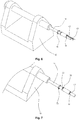
Fig. 6 is a structural schematic view when the heating bodies are installed during the process of assembling the smoke generator. -
Fig. 7 is a structural schematic view when one heating body is installed in the process for assembling the smoke generator. -
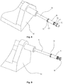
Fig. 8 is a structural schematic view when the fastener is installed in the process for assembling the smoke generator. -
Fig. 9 is a structural schematic view when the base is installed in the process for assembling the smoke generator. -
Fig. 10 is a sectional view for illustrating the structure of the smoke suction device comprising the smoke generator according to the invention. - In order to more clearly illustrate the technical problems to be solved by the invention, and the technical solution and advantageous effects thereof, the invention is further described in detail by combining the following examples and the drawings. It should be understood that the specific examples as described below are only used for explaining the invention, but not for restricting the invention.
- As shown in
Figs. 1 ,2 , and3 , the example discloses asmoke generator 100 for assembling a smoke suction device in combination with the supply power source 200 (as shown inFig. 10 ). The smoke generator comprises a supportingpipe 10 made of heat resistant materials, a plurality ofheating bodies 60 having afirst end 63 and asecond end 64 that are disposed in the supporting pipe, afirst support 20 having agas outlet 21 and asecond support 30 having agas inlet 31, thefirst support 20 and thesecond support 30 being disposed on the two ends of the supporting pipe, wherein both the first support and the second support are installed with a plurality of positioning portions. The first end of the plurality of heating bodies is disposed on the first support and bent onto the positioning portion of the first support, and the second end is disposed on the second support and bent onto the positioning portion of the second support. Theheating bodies 60 surrounds acavity 11 that is adapted to be filled withsolid smoking material 300. When thesmoke generator 100 is in operation, the gas stream flows into thecavity 11 via thegas inlet 31, and discharged from thecavity 11 via thegas outlet 21. - As shown in
Fig. 4 , in the example, theheating bodies 60 are in a sheet form, and the number of theheating bodies 60 is set to be five. The second ends 64 of theindividual heating bodies 60 are divided intofirst pins 61 andsecond pins 62 adaptable for electrical connection to the electrodes of externalsupply powder source 200, and the individualfirst pins 61, after being bent, are positioned onto thefirst support 20 and the individualfirst pins 61 are contacted with each other to form electrical connections. - Further, as shown in
Figs. 2 and3 , thesmoke generator 100 further comprises anon-conductive fastener 50 that is partially fastened in thegas inlet 31, and thefastener 50 does not block thegas inlet 31. Thefastener 50 is used to fix the individual fist pins 61 and separate thefirst pins 61 from thesecond pins 62 to prevent false contact conduction between thefirst pins 61 and the second pins 62 upon installation that can result in the rejection of the finished products. In the example, thefastener 50 is engaged with the base 40 on its outer surface, and the base 40 will not block thegas inlet 31. The base is used to fix the individualsecond pins 62 between thefastener 50 and thebase 40. In other examples, thebase 40 and thefattener 50 may be connected by the means of the sleeving connection. - As shown in
Fig. 3 , both thefirst support 20 and thesecond support 30 are installed with a plurality of positioning portions for fixing thefirst end 63 and thesecond end 64, and thefirst end 63 andsecond end 64 of theheating bodies 60 are bent onto the positioning portions of thefirst support 20 and thesecond support 30 respectively. In the example, thefirst support 20 is installed with agroove 22 adapted to contain the bent terminal portion of thefirst end 63 of theheating bodies 60 thereon, and thesecond support 30 is installed with agroove 32 adapted to contain the bend terminal portion of thefirst pins 61 of theheating bodies 60 thereon. Due to the installation regarding thegroove 22 on thefirst support 20 and thegroove 32 on thesecond support 30, after theheating bodies 60 are bent onto thefirst support 20 and thesecond support 30, it can prevent the movement of theindividual heating bodies 60 upon assembly, and assure the prepared finished products to have beneficial effect that a stable smoke quantity can be persistently produced. - In order to further fix the
heating bodies 60, as shown inFigs. 1 and2 , thesmoke generator 100 further comprises a fixingcap 70 that is engaged at the periphery of thefirst support 20, and the fixingcap 70 will not block thegas outlet 70. The fixingcap 70 presses onto thefirst end 63 of theheating bodies 60 to fix it. - In the example, the supporting
pipe 10 is made of a metallic material. Theheating bodies 60 is supported by thefirst support 20 and thesecond support 30, and it is not in electric contact with the supportingpipe 20. In other embodiments, the supportingpipe 10 also can be made of ceramics and other heat resistant materials. - As shown in
Figure 5 , a plurality of throughholes 12 are further disposed on the side of the supportingpipe 10, and the throughholes 12 can pass through thecavity 11. The through holes 12 can be used for air entrance and have the same functions as thegas inlet 31. The objective of the through holes is to render the entrance of gases to thecavity 11 to be more gentle and uniform. When theheating bodies 60 heat thesmoking material 300, smoke may be more quickly extracted. -
Figs. 6, 7 ,8, and 9 are schematic views for illustrating the method for assembling thesmoke generator 100. In the method, an assembling tool is usually used, and the assembling tool primarily comprises asubstrate 92 and an assemblingrod 91 disposed on thesubstrate 92. The size of the assemblingrod 91 is adapted to the size of thecavity 11. Particularly, the assembling method comprises the steps: - a). fixing a
first support 20 and asecond support 30 respectively at two ends of a supportingpipe 10; - b). sleeving a fixing
cap 70 onto an assemblingrod 91 that is adapted to pass through the supportingpipe 10; - c). sleeving the supporting
pipe 10 obtained in the step a) onto the assemblingrod 91, and engaging the fixingcap 70 onto thefirst support 20 along the assemblingrod 91; - d). inserting a
first end 63 of theheating bodies 60 into a gap between the supportingpipe 10 and the assemblingrod 91 along the end of thesecond support 30 until thefirst end 63 of theheating bodies 60 extends out of the end of thefirst support 20; - e). respectively bending two ends of the
heating bodies 60 onto positioning portions of thefirst support 20 andsecond support 30 to fix theheating bodies 60; and - f). successively fixing the
individual heating bodies 60 along the circumferential direction of the supportingpipe 10 onto thefirst support 30 and thesecond support 30, so that the plurality ofheating bodies 60 surround acavity 11 that is adapted to be filled with solid smoking materials, wherein thefirst pins 61 of thesecond end 64 of theindividual heating bodies 60, after being bent, are positioned on the positioning portions of thesecond support 30 and the plurality offirst pins 61 are contacted with each other, and thesecond pins 62 are intermittently fixed between thefastener 50 and thebase 40, and pressing the fixingcap 70 onto thefirst end 63 of theheating bodies 60. - For example, the
smoke generator 100 as shown inFig. 1 comprises fiveheating bodies 60, a fixingcap 70, afastener 50 and abase 40. Hence, after the step c) is completed, the fiveheating bodies 60, according to the step d), are assembled onto the supportingpipe 10 one by one; then according to the step e), the first ends 63 of the fiveheating bodies 60 are bent into thegroove 22 one by one, and then the first pins 61 on thesecond end 64 are bent into thegroove 32 one by one. - At last, as shown in
Figure 8 , thefastener 50 is sleeved onto the assemblingrod 91, and a part of thefastener 50 is installed into thegas inlet 31. Further, as shown inFigure 9 , thebase 40 engages the outer surface of thefattener 50. - In the example, the
solid smoking material 300 is solid tobacco. In other examples, thesolid smoking material 300 may further be tobacco paste or herb. - The assembling method comprises the steps:
- a). fixing a
first support 20 and asecond support 30 at two ends of a supportingpipe 10 respectively; - b). sleeving the supporting
pipe 10 obtained in the step a) onto an assemblingrod 91 adapted to pass through the supportingpipe 10; - c). inserting a
first end 63 of theheating bodies 60 into a gap between the supportingpipe 10 and the assemblingrod 91 along the end of thesecond support 30 until thefirst end 63 of theheating bodies 60 extends out of the end of thefirst support 20; - d). respectively bending two ends of the
heating bodies 60 onto positioning portions of thefirst support 20 andsecond support 30 to fix theheating bodies 60; - e). successively fixing the
individual heating bodies 60 along the circumferential direction of the supportingpipe 10 onto thefirst support 20 and thesecond support 30, so that the plurality ofheating bodies 60 surround acavity 11 that is adapted to be filled with solid smoking materials, wherein thefirst pins 61 of thesecond end 64 of theindividual heating bodies 60, after being bent, are positioned on the positioning portions of thesecond support 30 and the plurality offirst pins 61 are contacted with each other, and thesecond pins 62 are intermittently fixed between thefastener 50 and thebase 40; and - f). detaching the supporting
pipe 10, further sleeving the supportingpipe 10 onto the assemblingrod 91 after the fixingcap 70 is sleeved onto the assemblingrod 91, engaging the fixingcap 70 onto thefirst support 20 along the assemblingrod 91 and pressing the fixingcap 70 onto thefirst end 63 of theheating bodies 60. - The above specific examples are used to illustrate the principles and embodiments of the invention. It should be understood that the above embodiments are only used for aiding the understandings to the invention, and they cannot be understood to be restrict the invention. For a person skilled in the art, according to the concept of the invention, any slight variations or equivalent substitutions to the structural shape or configuration of the invention should be contained in the claimed protection scope.
Claims (10)
- A smoke generator, characterized in that the smoke generator (100) comprises: a supporting pipe (10), a plurality of heating bodies (60) having a first end (63) and a second end (64) that are disposed in the supporting pipe (10), a first support (20) having an gas outlet (21) and a second support (30) having a gas inlet (31), the first support (20) and the second support (30) being respectively disposed at the two ends of the supporting pipe (10), and a plurality of positioning portions being disposed onto the first support (20) and the second support (30), wherein the first end (63) of each of the plurality of heating bodies (60) is disposed onto the first support (20) and bent onto the positioning portions of the first support (20), and the second end (64) of each of the plurality of heating bodies (60) is disposed on the second support (30); the second end (64) of the heating bodies (60) includes a first pin (61) and a second pin (62), in which the second pin (62) extends out of the second support (30), and the first pin (61) is bent into an arc and then fixed onto the positioning portions of the second support (30); the plurality of heating bodies (60) surrounds a cavity (11) that is adapted to be filled with smoking materials; and a plurality of through holes (12) for gas entrance are optionally disposed onto the sidewalls of the supporting pipe (10).
- A method for assembling a smoke generator, wherein the smoke generator (100) comprises: a supporting pipe (10), a plurality of heating bodies (60) having a first end (63) and a second end (64) that are disposed in the supporting pipe (10), a first support (20) having an gas outlet (21) and a second support (30) having a gas inlet (31), the first support (20) and the second support (30) being respectively disposed at the two ends of the supporting pipe (10), and a plurality of positioning portions being disposed onto the first support (20) and the second support (30), wherein the first end (63) of each of the plurality of heating bodies (60) is disposed onto the first support (20) and bent onto the positioning portions of the first support (20), and the second end (64) of each of the plurality of heating bodies (60) is disposed on the second support (30) and bent onto the positioning portions of the second support (30); and the plurality of heating bodies (60) surrounds a cavity (11) that is adapted to be filled with smoking materials, characterized in that, the method for assembling the smoke generator comprises the steps of:a). fixing a first support (20) and a second support (30) at two ends of a supporting pipe (10) respectively;b). sleeving the supporting pipe (10) obtained in the step a) onto an assembling rod (91) adapted to pass through the supporting pipe (10);c). inserting a first end (63) of the heating bodies (60) into a gap between the supporting pipe (10) and the assembling rod (91) along the end of the second support (30) until the first end (63) of the heating bodies (60) extends out of the end of the first support (20);d). respectively bending two ends of the heating bodies (60) onto positioning portions of the first support (20) and second support (30) to fix the heating bodies (60); ande). successively fixing the individual heating bodies (60) along the circumferential direction of the supporting pipe (10) onto the first support (20) and the second support (30), so that the plurality of heating bodies (60) surround a cavity (11) that is adapted to be filled with solid smoking materials.
- The method for assembling a smoke generator according to claim 2, characterized in that the assembling rod (91) is a part of an assembling tool, and the assembling tool comprises a substrate (92) and an assembling rod (91) disposed on the substrate (92).
- The method for assembling a smoke generator according to claim 2, characterized in that the second end (64) of each heating body (60) of the smoke generator (100) is divided into a first pin (61) and a second pin (62) that are adaptable for electrical connection to the electrodes of the external supply powder source, and the smoke generator (100) further comprises a non-conductive fastener (50) that is fastened in the gas inlet (31), and a base (40) that is engaged or sleeved onto the fastener (50); in the step d) of the method for assembling the smoke generator, the first pin (61) of the second end (64) of each heating body (60), after being bent, is positioned onto the position portion of the second support (30), and the plurality of the first pins (61) are brought into contact with each other, and the individual second pins (62) are intermittently fixed between the fastener (50) and the base (40).
- The method for assembling a smoke generator according to claim 2, characterized in that the positioning portion of the first support (20) or the second support (30) is a groove that is adapted to contain the bent first end (63) or bent second end (64) of the heating bodies (60).
- The method for assembling a smoke generator according to claim 2, characterized in that the smoke generator (100) further comprises a fixing cap (70) that engages the first support (20), and the method for assembling the smoke generator further comprises the step:f). detaching the supporting pipe (10), further sleeving the supporting pipe (10) onto the assembling rod (91) after the fixing cap (70) is sleeved onto the assembling rod (91), and engaging the fixing cap (70) onto the first support (20) along the assembling rod (91) while the fixing cap (70) is pressured onto the first end (63) of the heating bodies (60).
- A method of assembling a smoke generator, wherein the smoke generator (100) comprises: a supporting pipe (10), a plurality of heating bodies (60) having a first end (63) and a second end (64) that are disposed in the supporting pipe (10), a first support (20) having an gas outlet (21) and a second support (30) having a gas inlet (31), the first support (20) and the second support (30) being respectively disposed at the two ends of the supporting pipe (10), and a plurality of positioning portions being disposed onto the first support (20) and the second support (30), wherein the first end (63) of each of the plurality of heating bodies (60) is disposed onto the first support (20) and bent onto the positioning portions of the first support (20), and the second end (64) of each of the plurality of heating bodies (60) is disposed on the second support (30) and bent onto the positioning portions of the second support (30); and the plurality of heating bodies (60) surrounds a cavity (11) that is adapted to be filled with smoking materials, wherein the smoke generator (100) further comprises a fixing cap (70) that engages the first support (20), characterized in that the method comprises the steps of:a). fixing a first support (20) and a second support (30) respectively at two ends of a supporting pipe (10);b). sleeving a fixing cap (70) onto an assembling rod (91) that is adapted to pass through the supporting pipe (10);c). sleeving the supporting pipe (10) obtained in the step a) onto the assembling rod (91), and engaging the fixing cap (70) onto the first support (20) along the assembling rod (91);d). inserting a first end (63) of the heating bodies (60) into a gap between the supporting pipe (10) and the assembling rod (91) along the end of the second support (30) until the first end (63) of the heating bodies (60) extends out of the end of the first support (20);e). respectively bending two ends of the heating bodies (60) onto positioning portions of the first support (20) and second support (30) to fix the heating bodies (60); andf). successively fixing the individual heating bodies (60) along the circumferential direction of the supporting pipe (10) onto the first support (20) and the second support (30), so that the plurality of heating bodies (60) surround a cavity (11) that is adapted to be filled with solid smoking materials, and pressing the fixing cap (70) onto the first end (63) of the heating bodies (60).
- The method for assembling a smoke generator according to claim 7, characterized in that the assembling rod (91) is a part of an assembling tool, and the assembling tool comprises a substrate (92) and an assembling rod (91) disposed on the substrate (92).
- The method for assembling a smoke generator according to claim 7, characterized in that the second end (64) of each heating body (60) of the smoke generator (100) is divided into a first pin (61) and a second pin (62) that are adaptable for electrical connection to the electrodes of the external supply powder source, and the smoke generator (100) further comprises a non-conductive fastener (50) that is fastened in the gas inlet (31), and a base (40) that is engaged or sleeved onto the fastener (50); in the step e) of the method for assembling the smoke generator, the first pin (61) of the second end (64) of each heating body (60), after being bent, is positioned onto the position portion of the second support (30), and the plurality of the first pins (61) are brought into contact with each other, and the individual second pins (62) are intermittently fixed between the fastener (50) and the base (40).
- The method of assembling a smoke generator according to claim 7, characterized in that the positioning portion of the first support (20) or the second support (30) is a groove that is adapted to contain the bent first end (63) or bent second end (64) of the heating bodies (60).
Priority Applications (2)
| Application Number | Priority Date | Filing Date | Title |
|---|---|---|---|
| PL15881702T PL3257386T3 (en) | 2015-02-11 | 2015-06-23 | Smoke generator and assembling method therefor |
| RSP20191087 RS59279B1 (en) | 2015-02-11 | 2015-06-23 | Smoke generator and assembling method therefor |
Applications Claiming Priority (3)
| Application Number | Priority Date | Filing Date | Title |
|---|---|---|---|
| CN201520098744.1U CN204426695U (en) | 2015-02-11 | 2015-02-11 | Be applicable to the heater heating smoking article |
| CN201510112097.XA CN104770893B (en) | 2015-03-13 | 2015-03-13 | A kind of assemble method of aerosol producer |
| PCT/CN2015/082079 WO2016127541A1 (en) | 2015-02-11 | 2015-06-23 | Smoke generator and assembling method therefor |
Publications (3)
| Publication Number | Publication Date |
|---|---|
| EP3257386A1 true EP3257386A1 (en) | 2017-12-20 |
| EP3257386A4 EP3257386A4 (en) | 2018-08-01 |
| EP3257386B1 EP3257386B1 (en) | 2019-06-19 |
Family
ID=56614061
Family Applications (1)
| Application Number | Title | Priority Date | Filing Date |
|---|---|---|---|
| EP15881702.3A Not-in-force EP3257386B1 (en) | 2015-02-11 | 2015-06-23 | Smoke generator and assembling method therefor |
Country Status (11)
| Country | Link |
|---|---|
| EP (1) | EP3257386B1 (en) |
| JP (1) | JP6368866B2 (en) |
| KR (1) | KR101957877B1 (en) |
| DE (1) | DE202015009477U1 (en) |
| DK (1) | DK3257386T3 (en) |
| ES (1) | ES2744185T3 (en) |
| HU (1) | HUE045994T2 (en) |
| PL (1) | PL3257386T3 (en) |
| PT (1) | PT3257386T (en) |
| RS (1) | RS59279B1 (en) |
| WO (1) | WO2016127541A1 (en) |
Cited By (5)
| Publication number | Priority date | Publication date | Assignee | Title |
|---|---|---|---|---|
| WO2020038780A1 (en) * | 2018-08-22 | 2020-02-27 | Philip Morris Products S.A. | Heater assembly with anchoring legs |
| WO2023065333A1 (en) * | 2021-10-22 | 2023-04-27 | Philip Morris Products S.A. | System and method for assembly of a heater module for an aerosol generating device |
| WO2024068886A1 (en) * | 2022-09-30 | 2024-04-04 | Nicoventures Trading Limited | Aerosol provision device |
| US12022869B2 (en) | 2018-10-12 | 2024-07-02 | Jt International S.A. | Aerosol generation device, and heating chamber therefor |
| US12256780B2 (en) | 2019-12-19 | 2025-03-25 | Philip Morris Products S.A. | Cartridge for an aerosol-generating system, an aerosol-generating system including a cartridge, and a method of manufacturing a heater assembly and cartridge for an aerosol-generating system |
Families Citing this family (26)
| Publication number | Priority date | Publication date | Assignee | Title |
|---|---|---|---|---|
| CA3063034C (en) | 2017-05-11 | 2021-04-13 | Kt&G Corporation | Vaporizer and aerosol generation device including same |
| KR20180124739A (en) | 2017-05-11 | 2018-11-21 | 주식회사 케이티앤지 | An aerosol generating device for controlling the temperature of a heater according to the type of cigarette and method thereof |
| KR20190049391A (en) | 2017-10-30 | 2019-05-09 | 주식회사 케이티앤지 | Aerosol generating apparatus having heater |
| KR102180421B1 (en) | 2017-10-30 | 2020-11-18 | 주식회사 케이티앤지 | Apparatus for generating aerosols |
| KR102138245B1 (en) | 2017-10-30 | 2020-07-28 | 주식회사 케이티앤지 | Aerosol generating apparatus |
| KR102057216B1 (en) | 2017-10-30 | 2019-12-18 | 주식회사 케이티앤지 | An apparatus for generating aerosols and A heater assembly therein |
| WO2019088587A2 (en) * | 2017-10-30 | 2019-05-09 | 주식회사 케이티앤지 | Aerosol generation device and heater for aerosol generation device |
| KR102141648B1 (en) * | 2017-10-30 | 2020-08-05 | 주식회사 케이티앤지 | An apparatus for generating aerosols and a method for controlling the apparatus |
| US11528936B2 (en) | 2017-10-30 | 2022-12-20 | Kt&G Corporation | Aerosol generating device |
| JP6840291B2 (en) | 2017-10-30 | 2021-03-10 | ケイティー アンド ジー コーポレイション | Aerosol generator |
| CN111182802A (en) | 2017-10-30 | 2020-05-19 | 韩国烟草人参公社 | Optical module and aerosol-generating device comprising the same |
| KR102057215B1 (en) | 2017-10-30 | 2019-12-18 | 주식회사 케이티앤지 | Method and apparatus for generating aerosols |
| HUE066012T2 (en) | 2017-10-30 | 2024-07-28 | Kt & G Corp | Aerosol generating device and method for controlling same |
| KR102138246B1 (en) | 2017-10-30 | 2020-07-28 | 주식회사 케이티앤지 | Vaporizer and aerosol generating apparatus comprising the same |
| WO2019088580A2 (en) | 2017-10-30 | 2019-05-09 | 주식회사 케이티앤지 | Aerosol generating device |
| KR101959227B1 (en) * | 2018-01-02 | 2019-03-19 | 주식회사 바이퍼 | Apparatus for atomizing electronic cigarette |
| KR102274248B1 (en) | 2018-04-24 | 2021-07-07 | 주식회사 아모센스 | heater assembly for cigarette type electronic device and cigarette type electronic device including the same |
| US12458064B2 (en) | 2018-08-15 | 2025-11-04 | Nicoventures Trading Limited | Apparatus for heating an article including an aerosolizable medium, a method of manufacturing the apparatus and an aerosolizable material article for use with the apparatus |
| CN109007984B (en) * | 2018-09-17 | 2025-01-07 | 深圳市合元科技有限公司 | Heating element and heater |
| KR102381055B1 (en) * | 2019-12-20 | 2022-03-31 | 주식회사 이엠텍 | Heating film assembly of microparticle generator |
| CN113115990A (en) * | 2020-01-15 | 2021-07-16 | 深圳市合元科技有限公司 | Aerosol generating device and infrared emitter |
| CN118119302A (en) * | 2021-12-06 | 2024-05-31 | 日本烟草产业株式会社 | Aerosol Generating System |
| WO2023105558A1 (en) * | 2021-12-06 | 2023-06-15 | 日本たばこ産業株式会社 | Aerosol generation system |
| EP4403055A4 (en) * | 2021-12-06 | 2025-07-02 | Japan Tobacco Inc | AEROSOL GENERATION SYSTEM |
| KR102833034B1 (en) * | 2022-03-04 | 2025-07-11 | 주식회사 이엠텍 | Heater for aerosol generator |
| EP4656075A1 (en) * | 2023-03-31 | 2025-12-03 | Japan Tobacco Inc. | Aerosol generation device |
Family Cites Families (13)
| Publication number | Priority date | Publication date | Assignee | Title |
|---|---|---|---|---|
| US5665262A (en) * | 1991-03-11 | 1997-09-09 | Philip Morris Incorporated | Tubular heater for use in an electrical smoking article |
| ATE121909T1 (en) * | 1991-03-11 | 1995-05-15 | Philip Morris Prod | FLAVOR PRODUCING ITEMS. |
| US5505214A (en) * | 1991-03-11 | 1996-04-09 | Philip Morris Incorporated | Electrical smoking article and method for making same |
| US5591368A (en) * | 1991-03-11 | 1997-01-07 | Philip Morris Incorporated | Heater for use in an electrical smoking system |
| CR4906A (en) * | 1993-09-10 | 1994-09-09 | Philip Morris Prod | ELECTRIC SMOKING SYSTEM TO DISTRIBUTE FLAVORS AND METHOD FOR ITS MANUFACTURE |
| CN102326869B (en) * | 2011-05-12 | 2013-04-03 | 陈志平 | Atomization nozzle of electronic atomization inhaler |
| CN202456410U (en) * | 2011-11-22 | 2012-10-03 | 深圳市合元科技有限公司 | Atomization device of electronic cigarette |
| AU2012360817B2 (en) * | 2011-12-30 | 2017-09-07 | Philip Morris Products S.A. | Aerosol generating device with improved temperature distribution |
| US20140261487A1 (en) * | 2013-03-14 | 2014-09-18 | R. J. Reynolds Tobacco Company | Electronic smoking article with improved storage and transport of aerosol precursor compositions |
| CN103504478B (en) * | 2013-05-07 | 2016-01-27 | 深圳市合元科技有限公司 | Electronic smoke atomizer and electronic cigarette |
| CN203505586U (en) * | 2013-09-29 | 2014-04-02 | 云南昆船数码科技有限公司 | Non-combustion smogless electronic cigarette |
| CN203505592U (en) * | 2013-11-13 | 2014-04-02 | 深圳市克莱鹏科技有限公司 | Electronic cigarette atomizer |
| CN203748673U (en) * | 2013-12-30 | 2014-08-06 | 深圳市合元科技有限公司 | Smoke generator and electronic cigarette comprising same |
-
2015
- 2015-06-23 EP EP15881702.3A patent/EP3257386B1/en not_active Not-in-force
- 2015-06-23 RS RSP20191087 patent/RS59279B1/en unknown
- 2015-06-23 PT PT15881702T patent/PT3257386T/en unknown
- 2015-06-23 PL PL15881702T patent/PL3257386T3/en unknown
- 2015-06-23 ES ES15881702T patent/ES2744185T3/en active Active
- 2015-06-23 WO PCT/CN2015/082079 patent/WO2016127541A1/en not_active Ceased
- 2015-06-23 HU HUE15881702A patent/HUE045994T2/en unknown
- 2015-06-23 DK DK15881702.3T patent/DK3257386T3/en active
- 2015-06-23 JP JP2017548253A patent/JP6368866B2/en not_active Expired - Fee Related
- 2015-06-23 DE DE202015009477.5U patent/DE202015009477U1/en not_active Expired - Lifetime
- 2015-06-23 KR KR1020177024037A patent/KR101957877B1/en not_active Expired - Fee Related
Cited By (7)
| Publication number | Priority date | Publication date | Assignee | Title |
|---|---|---|---|---|
| WO2020038780A1 (en) * | 2018-08-22 | 2020-02-27 | Philip Morris Products S.A. | Heater assembly with anchoring legs |
| RU2756265C1 (en) * | 2018-08-22 | 2021-09-28 | Филип Моррис Продактс С.А. | Heater assembly with mounting legs |
| US11957173B2 (en) | 2018-08-22 | 2024-04-16 | Philip Morris Products S.A. | Heater assembly with anchoring legs |
| US12022869B2 (en) | 2018-10-12 | 2024-07-02 | Jt International S.A. | Aerosol generation device, and heating chamber therefor |
| US12256780B2 (en) | 2019-12-19 | 2025-03-25 | Philip Morris Products S.A. | Cartridge for an aerosol-generating system, an aerosol-generating system including a cartridge, and a method of manufacturing a heater assembly and cartridge for an aerosol-generating system |
| WO2023065333A1 (en) * | 2021-10-22 | 2023-04-27 | Philip Morris Products S.A. | System and method for assembly of a heater module for an aerosol generating device |
| WO2024068886A1 (en) * | 2022-09-30 | 2024-04-04 | Nicoventures Trading Limited | Aerosol provision device |
Also Published As
| Publication number | Publication date |
|---|---|
| RS59279B1 (en) | 2019-10-31 |
| JP2018504918A (en) | 2018-02-22 |
| HUE045994T2 (en) | 2020-01-28 |
| KR20170117444A (en) | 2017-10-23 |
| KR101957877B1 (en) | 2019-03-13 |
| JP6368866B2 (en) | 2018-08-01 |
| DK3257386T3 (en) | 2019-09-09 |
| ES2744185T3 (en) | 2020-02-24 |
| PL3257386T3 (en) | 2019-12-31 |
| EP3257386B1 (en) | 2019-06-19 |
| PT3257386T (en) | 2019-09-13 |
| WO2016127541A1 (en) | 2016-08-18 |
| EP3257386A4 (en) | 2018-08-01 |
| DE202015009477U1 (en) | 2017-11-02 |
Similar Documents
| Publication | Publication Date | Title |
|---|---|---|
| EP3257386B1 (en) | Smoke generator and assembling method therefor | |
| CN104770893B (en) | A kind of assemble method of aerosol producer | |
| CN104770895B (en) | Heater and aerosol producer for tobacco product | |
| EP3078283A1 (en) | Tobacco heating device | |
| TWI612908B (en) | Method for manufacturing atomization unit and atomization unit | |
| CN204377931U (en) | Adopt the electronic smoke atomizer of two interchangeable atomising head of heating wire | |
| CN104770894B (en) | Aerosol producer and fume extraction device | |
| CN107529822B (en) | Electronic device for generating smoke and method for generating smoke | |
| CN204070571U (en) | Baking-type atomizer and electronic cigarette | |
| WO2018205247A1 (en) | Cigarette flue-curing device | |
| US20240251856A1 (en) | Heating structure of aerosol generating device and aerosol generating device | |
| CN206586400U (en) | Heating member, atomizer and electronic cigarette | |
| JP6978580B2 (en) | Heaters for aerosol generators and aerosol generators | |
| CN208175984U (en) | A kind of electronic atomization device | |
| CN106572702A (en) | electronic cigarette | |
| CN209931485U (en) | Cigarette heater and electric heating smoking device | |
| CN111743208A (en) | Atomizer core heating oil guide fixing component and its forming method | |
| WO2020024751A1 (en) | Atomizing device and electronic cigarette | |
| CN207075560U (en) | Device for flue-cured tobacco | |
| CN204483027U (en) | Aerosol producer | |
| CN206390305U (en) | A kind of Convective Heating electronic cigarette flue-cured tobacco | |
| CN209825227U (en) | Heating body device for heating non-burning smoking set | |
| CN206880074U (en) | Electronic cigarette atomizing cored structure and electronic smoke atomizer using metal felt as heat generating components | |
| CN110384261A (en) | It is a kind of to heat the smoking set that do not burn | |
| CN204146322U (en) | Baking-type atomizer and there is the electronic cigarette of this atomizer |
Legal Events
| Date | Code | Title | Description |
|---|---|---|---|
| STAA | Information on the status of an ep patent application or granted ep patent |
Free format text: STATUS: THE INTERNATIONAL PUBLICATION HAS BEEN MADE |
|
| PUAI | Public reference made under article 153(3) epc to a published international application that has entered the european phase |
Free format text: ORIGINAL CODE: 0009012 |
|
| STAA | Information on the status of an ep patent application or granted ep patent |
Free format text: STATUS: REQUEST FOR EXAMINATION WAS MADE |
|
| 17P | Request for examination filed |
Effective date: 20170911 |
|
| AK | Designated contracting states |
Kind code of ref document: A1 Designated state(s): AL AT BE BG CH CY CZ DE DK EE ES FI FR GB GR HR HU IE IS IT LI LT LU LV MC MK MT NL NO PL PT RO RS SE SI SK SM TR |
|
| AX | Request for extension of the european patent |
Extension state: BA ME |
|
| DAV | Request for validation of the european patent (deleted) | ||
| DAX | Request for extension of the european patent (deleted) | ||
| A4 | Supplementary search report drawn up and despatched |
Effective date: 20180702 |
|
| RIC1 | Information provided on ipc code assigned before grant |
Ipc: A24F 47/00 20060101AFI20180626BHEP |
|
| GRAP | Despatch of communication of intention to grant a patent |
Free format text: ORIGINAL CODE: EPIDOSNIGR1 |
|
| STAA | Information on the status of an ep patent application or granted ep patent |
Free format text: STATUS: GRANT OF PATENT IS INTENDED |
|
| INTG | Intention to grant announced |
Effective date: 20181213 |
|
| RIN1 | Information on inventor provided before grant (corrected) |
Inventor name: YUAN, DALIN Inventor name: SHANG, SHANZHAI Inventor name: SUN, ZHIYONG Inventor name: YANG, LIU Inventor name: ZHU, DONGLAI Inventor name: MIAO, MINGMING Inventor name: TANG, JIANGUO Inventor name: LIAO, XIAOXIANG Inventor name: ZHAO, WEI Inventor name: ZHENG, XUDONG Inventor name: CHEN, YONGKUAN Inventor name: LI, SHOUBO Inventor name: LEI, PING Inventor name: YANG, JI Inventor name: XIANG, NENGJUN |
|
| GRAS | Grant fee paid |
Free format text: ORIGINAL CODE: EPIDOSNIGR3 |
|
| GRAJ | Information related to disapproval of communication of intention to grant by the applicant or resumption of examination proceedings by the epo deleted |
Free format text: ORIGINAL CODE: EPIDOSDIGR1 |
|
| GRAL | Information related to payment of fee for publishing/printing deleted |
Free format text: ORIGINAL CODE: EPIDOSDIGR3 |
|
| STAA | Information on the status of an ep patent application or granted ep patent |
Free format text: STATUS: REQUEST FOR EXAMINATION WAS MADE |
|
| GRAR | Information related to intention to grant a patent recorded |
Free format text: ORIGINAL CODE: EPIDOSNIGR71 |
|
| STAA | Information on the status of an ep patent application or granted ep patent |
Free format text: STATUS: GRANT OF PATENT IS INTENDED |
|
| GRAA | (expected) grant |
Free format text: ORIGINAL CODE: 0009210 |
|
| STAA | Information on the status of an ep patent application or granted ep patent |
Free format text: STATUS: THE PATENT HAS BEEN GRANTED |
|
| INTC | Intention to grant announced (deleted) | ||
| INTG | Intention to grant announced |
Effective date: 20190509 |
|
| AK | Designated contracting states |
Kind code of ref document: B1 Designated state(s): AL AT BE BG CH CY CZ DE DK EE ES FI FR GB GR HR HU IE IS IT LI LT LU LV MC MK MT NL NO PL PT RO RS SE SI SK SM TR |
|
| REG | Reference to a national code |
Ref country code: GB Ref legal event code: FG4D |
|
| REG | Reference to a national code |
Ref country code: CH Ref legal event code: EP |
|
| REG | Reference to a national code |
Ref country code: IE Ref legal event code: FG4D |
|
| REG | Reference to a national code |
Ref country code: DE Ref legal event code: R096 Ref document number: 602015032517 Country of ref document: DE |
|
| REG | Reference to a national code |
Ref country code: AT Ref legal event code: REF Ref document number: 1144356 Country of ref document: AT Kind code of ref document: T Effective date: 20190715 |
|
| REG | Reference to a national code |
Ref country code: RO Ref legal event code: EPE |
|
| REG | Reference to a national code |
Ref country code: NL Ref legal event code: FP |
|
| REG | Reference to a national code |
Ref country code: DK Ref legal event code: T3 Effective date: 20190904 |
|
| REG | Reference to a national code |
Ref country code: SE Ref legal event code: TRGR |
|
| REG | Reference to a national code |
Ref country code: CH Ref legal event code: NV Representative=s name: VALIPAT S.A. C/O BOVARD SA NEUCHATEL, CH Ref country code: PT Ref legal event code: SC4A Ref document number: 3257386 Country of ref document: PT Date of ref document: 20190913 Kind code of ref document: T Free format text: AVAILABILITY OF NATIONAL TRANSLATION Effective date: 20190827 |
|
| PG25 | Lapsed in a contracting state [announced via postgrant information from national office to epo] |
Ref country code: LT Free format text: LAPSE BECAUSE OF FAILURE TO SUBMIT A TRANSLATION OF THE DESCRIPTION OR TO PAY THE FEE WITHIN THE PRESCRIBED TIME-LIMIT Effective date: 20190619 Ref country code: FI Free format text: LAPSE BECAUSE OF FAILURE TO SUBMIT A TRANSLATION OF THE DESCRIPTION OR TO PAY THE FEE WITHIN THE PRESCRIBED TIME-LIMIT Effective date: 20190619 Ref country code: AL Free format text: LAPSE BECAUSE OF FAILURE TO SUBMIT A TRANSLATION OF THE DESCRIPTION OR TO PAY THE FEE WITHIN THE PRESCRIBED TIME-LIMIT Effective date: 20190619 Ref country code: HR Free format text: LAPSE BECAUSE OF FAILURE TO SUBMIT A TRANSLATION OF THE DESCRIPTION OR TO PAY THE FEE WITHIN THE PRESCRIBED TIME-LIMIT Effective date: 20190619 Ref country code: NO Free format text: LAPSE BECAUSE OF FAILURE TO SUBMIT A TRANSLATION OF THE DESCRIPTION OR TO PAY THE FEE WITHIN THE PRESCRIBED TIME-LIMIT Effective date: 20190919 |
|
| REG | Reference to a national code |
Ref country code: LT Ref legal event code: MG4D |
|
| PG25 | Lapsed in a contracting state [announced via postgrant information from national office to epo] |
Ref country code: LV Free format text: LAPSE BECAUSE OF FAILURE TO SUBMIT A TRANSLATION OF THE DESCRIPTION OR TO PAY THE FEE WITHIN THE PRESCRIBED TIME-LIMIT Effective date: 20190619 |
|
| REG | Reference to a national code |
Ref country code: GR Ref legal event code: EP Ref document number: 20190402765 Country of ref document: GR Effective date: 20191128 |
|
| REG | Reference to a national code |
Ref country code: HU Ref legal event code: AG4A Ref document number: E045994 Country of ref document: HU |
|
| PG25 | Lapsed in a contracting state [announced via postgrant information from national office to epo] |
Ref country code: EE Free format text: LAPSE BECAUSE OF FAILURE TO SUBMIT A TRANSLATION OF THE DESCRIPTION OR TO PAY THE FEE WITHIN THE PRESCRIBED TIME-LIMIT Effective date: 20190619 Ref country code: SK Free format text: LAPSE BECAUSE OF FAILURE TO SUBMIT A TRANSLATION OF THE DESCRIPTION OR TO PAY THE FEE WITHIN THE PRESCRIBED TIME-LIMIT Effective date: 20190619 |
|
| REG | Reference to a national code |
Ref country code: ES Ref legal event code: FG2A Ref document number: 2744185 Country of ref document: ES Kind code of ref document: T3 Effective date: 20200224 |
|
| PG25 | Lapsed in a contracting state [announced via postgrant information from national office to epo] |
Ref country code: IS Free format text: LAPSE BECAUSE OF FAILURE TO SUBMIT A TRANSLATION OF THE DESCRIPTION OR TO PAY THE FEE WITHIN THE PRESCRIBED TIME-LIMIT Effective date: 20191019 Ref country code: SM Free format text: LAPSE BECAUSE OF FAILURE TO SUBMIT A TRANSLATION OF THE DESCRIPTION OR TO PAY THE FEE WITHIN THE PRESCRIBED TIME-LIMIT Effective date: 20190619 |
|
| PG25 | Lapsed in a contracting state [announced via postgrant information from national office to epo] |
Ref country code: MC Free format text: LAPSE BECAUSE OF FAILURE TO SUBMIT A TRANSLATION OF THE DESCRIPTION OR TO PAY THE FEE WITHIN THE PRESCRIBED TIME-LIMIT Effective date: 20190619 |
|
| PG25 | Lapsed in a contracting state [announced via postgrant information from national office to epo] |
Ref country code: IE Free format text: LAPSE BECAUSE OF NON-PAYMENT OF DUE FEES Effective date: 20190623 |
|
| PG25 | Lapsed in a contracting state [announced via postgrant information from national office to epo] |
Ref country code: IS Free format text: LAPSE BECAUSE OF FAILURE TO SUBMIT A TRANSLATION OF THE DESCRIPTION OR TO PAY THE FEE WITHIN THE PRESCRIBED TIME-LIMIT Effective date: 20200224 Ref country code: LU Free format text: LAPSE BECAUSE OF NON-PAYMENT OF DUE FEES Effective date: 20190623 |
|
| REG | Reference to a national code |
Ref country code: DE Ref legal event code: R097 Ref document number: 602015032517 Country of ref document: DE |
|
| PLBE | No opposition filed within time limit |
Free format text: ORIGINAL CODE: 0009261 |
|
| STAA | Information on the status of an ep patent application or granted ep patent |
Free format text: STATUS: NO OPPOSITION FILED WITHIN TIME LIMIT |
|
| PG2D | Information on lapse in contracting state deleted |
Ref country code: IS |
|
| PGFP | Annual fee paid to national office [announced via postgrant information from national office to epo] |
Ref country code: PT Payment date: 20200612 Year of fee payment: 6 Ref country code: DK Payment date: 20200622 Year of fee payment: 6 Ref country code: TR Payment date: 20200618 Year of fee payment: 6 Ref country code: CZ Payment date: 20200615 Year of fee payment: 6 Ref country code: GR Payment date: 20200619 Year of fee payment: 6 |
|
| 26N | No opposition filed |
Effective date: 20200603 |
|
| PG25 | Lapsed in a contracting state [announced via postgrant information from national office to epo] |
Ref country code: SI Free format text: LAPSE BECAUSE OF FAILURE TO SUBMIT A TRANSLATION OF THE DESCRIPTION OR TO PAY THE FEE WITHIN THE PRESCRIBED TIME-LIMIT Effective date: 20190619 |
|
| PGFP | Annual fee paid to national office [announced via postgrant information from national office to epo] |
Ref country code: SE Payment date: 20200625 Year of fee payment: 6 Ref country code: PL Payment date: 20200615 Year of fee payment: 6 Ref country code: HU Payment date: 20200609 Year of fee payment: 6 Ref country code: NL Payment date: 20200622 Year of fee payment: 6 Ref country code: RS Payment date: 20200611 Year of fee payment: 6 Ref country code: BG Payment date: 20200625 Year of fee payment: 6 |
|
| PGFP | Annual fee paid to national office [announced via postgrant information from national office to epo] |
Ref country code: AT Payment date: 20200618 Year of fee payment: 6 |
|
| PGFP | Annual fee paid to national office [announced via postgrant information from national office to epo] |
Ref country code: CH Payment date: 20200630 Year of fee payment: 6 |
|
| PG25 | Lapsed in a contracting state [announced via postgrant information from national office to epo] |
Ref country code: CY Free format text: LAPSE BECAUSE OF FAILURE TO SUBMIT A TRANSLATION OF THE DESCRIPTION OR TO PAY THE FEE WITHIN THE PRESCRIBED TIME-LIMIT Effective date: 20190619 |
|
| PG25 | Lapsed in a contracting state [announced via postgrant information from national office to epo] |
Ref country code: MT Free format text: LAPSE BECAUSE OF FAILURE TO SUBMIT A TRANSLATION OF THE DESCRIPTION OR TO PAY THE FEE WITHIN THE PRESCRIBED TIME-LIMIT Effective date: 20190619 |
|
| PGFP | Annual fee paid to national office [announced via postgrant information from national office to epo] |
Ref country code: IT Payment date: 20210630 Year of fee payment: 7 Ref country code: FR Payment date: 20210621 Year of fee payment: 7 Ref country code: RO Payment date: 20210617 Year of fee payment: 7 Ref country code: DE Payment date: 20210630 Year of fee payment: 7 |
|
| PGFP | Annual fee paid to national office [announced via postgrant information from national office to epo] |
Ref country code: GB Payment date: 20210623 Year of fee payment: 7 Ref country code: BE Payment date: 20210621 Year of fee payment: 7 |
|
| PGFP | Annual fee paid to national office [announced via postgrant information from national office to epo] |
Ref country code: ES Payment date: 20210722 Year of fee payment: 7 |
|
| REG | Reference to a national code |
Ref country code: DK Ref legal event code: EBP Effective date: 20210630 |
|
| REG | Reference to a national code |
Ref country code: SE Ref legal event code: EUG |
|
| PG25 | Lapsed in a contracting state [announced via postgrant information from national office to epo] |
Ref country code: CZ Free format text: LAPSE BECAUSE OF NON-PAYMENT OF DUE FEES Effective date: 20210623 Ref country code: RS Free format text: LAPSE BECAUSE OF NON-PAYMENT OF DUE FEES Effective date: 20210623 Ref country code: PT Free format text: LAPSE BECAUSE OF NON-PAYMENT OF DUE FEES Effective date: 20211223 |
|
| REG | Reference to a national code |
Ref country code: CH Ref legal event code: PL |
|
| REG | Reference to a national code |
Ref country code: NL Ref legal event code: MM Effective date: 20210701 |
|
| REG | Reference to a national code |
Ref country code: AT Ref legal event code: MM01 Ref document number: 1144356 Country of ref document: AT Kind code of ref document: T Effective date: 20210623 |
|
| PG25 | Lapsed in a contracting state [announced via postgrant information from national office to epo] |
Ref country code: LI Free format text: LAPSE BECAUSE OF NON-PAYMENT OF DUE FEES Effective date: 20210630 Ref country code: HU Free format text: LAPSE BECAUSE OF NON-PAYMENT OF DUE FEES Effective date: 20210624 Ref country code: CH Free format text: LAPSE BECAUSE OF NON-PAYMENT OF DUE FEES Effective date: 20210630 Ref country code: BG Free format text: LAPSE BECAUSE OF NON-PAYMENT OF DUE FEES Effective date: 20211231 Ref country code: AT Free format text: LAPSE BECAUSE OF NON-PAYMENT OF DUE FEES Effective date: 20210623 |
|
| PG25 | Lapsed in a contracting state [announced via postgrant information from national office to epo] |
Ref country code: SE Free format text: LAPSE BECAUSE OF NON-PAYMENT OF DUE FEES Effective date: 20210624 Ref country code: NL Free format text: LAPSE BECAUSE OF NON-PAYMENT OF DUE FEES Effective date: 20210701 Ref country code: GR Free format text: LAPSE BECAUSE OF NON-PAYMENT OF DUE FEES Effective date: 20220105 |
|
| PG25 | Lapsed in a contracting state [announced via postgrant information from national office to epo] |
Ref country code: MK Free format text: LAPSE BECAUSE OF FAILURE TO SUBMIT A TRANSLATION OF THE DESCRIPTION OR TO PAY THE FEE WITHIN THE PRESCRIBED TIME-LIMIT Effective date: 20190619 |
|
| PG25 | Lapsed in a contracting state [announced via postgrant information from national office to epo] |
Ref country code: DK Free format text: LAPSE BECAUSE OF NON-PAYMENT OF DUE FEES Effective date: 20210630 |
|
| REG | Reference to a national code |
Ref country code: DE Ref legal event code: R119 Ref document number: 602015032517 Country of ref document: DE |
|
| PG25 | Lapsed in a contracting state [announced via postgrant information from national office to epo] |
Ref country code: RO Free format text: LAPSE BECAUSE OF NON-PAYMENT OF DUE FEES Effective date: 20220623 |
|
| REG | Reference to a national code |
Ref country code: BE Ref legal event code: MM Effective date: 20220630 |
|
| GBPC | Gb: european patent ceased through non-payment of renewal fee |
Effective date: 20220623 |
|
| PG25 | Lapsed in a contracting state [announced via postgrant information from national office to epo] |
Ref country code: FR Free format text: LAPSE BECAUSE OF NON-PAYMENT OF DUE FEES Effective date: 20220630 |
|
| PG25 | Lapsed in a contracting state [announced via postgrant information from national office to epo] |
Ref country code: PL Free format text: LAPSE BECAUSE OF NON-PAYMENT OF DUE FEES Effective date: 20210623 Ref country code: GB Free format text: LAPSE BECAUSE OF NON-PAYMENT OF DUE FEES Effective date: 20220623 Ref country code: DE Free format text: LAPSE BECAUSE OF NON-PAYMENT OF DUE FEES Effective date: 20230103 Ref country code: BE Free format text: LAPSE BECAUSE OF NON-PAYMENT OF DUE FEES Effective date: 20220630 |
|
| PG25 | Lapsed in a contracting state [announced via postgrant information from national office to epo] |
Ref country code: IT Free format text: LAPSE BECAUSE OF NON-PAYMENT OF DUE FEES Effective date: 20220623 |
|
| REG | Reference to a national code |
Ref country code: ES Ref legal event code: FD2A Effective date: 20230731 |
|
| PG25 | Lapsed in a contracting state [announced via postgrant information from national office to epo] |
Ref country code: ES Free format text: LAPSE BECAUSE OF NON-PAYMENT OF DUE FEES Effective date: 20220624 |
|
| PG25 | Lapsed in a contracting state [announced via postgrant information from national office to epo] |
Ref country code: TR Free format text: LAPSE BECAUSE OF NON-PAYMENT OF DUE FEES Effective date: 20210623 |