EP3256770B1 - Leitungsrohr mit thermischer dämmung - Google Patents
Leitungsrohr mit thermischer dämmung Download PDFInfo
- Publication number
- EP3256770B1 EP3256770B1 EP16705894.0A EP16705894A EP3256770B1 EP 3256770 B1 EP3256770 B1 EP 3256770B1 EP 16705894 A EP16705894 A EP 16705894A EP 3256770 B1 EP3256770 B1 EP 3256770B1
- Authority
- EP
- European Patent Office
- Prior art keywords
- barrier
- outer shell
- polymer
- layer
- thermal insulation
- Prior art date
- Legal status (The legal status is an assumption and is not a legal conclusion. Google has not performed a legal analysis and makes no representation as to the accuracy of the status listed.)
- Active
Links
Images
Classifications
-
- F—MECHANICAL ENGINEERING; LIGHTING; HEATING; WEAPONS; BLASTING
- F16—ENGINEERING ELEMENTS AND UNITS; GENERAL MEASURES FOR PRODUCING AND MAINTAINING EFFECTIVE FUNCTIONING OF MACHINES OR INSTALLATIONS; THERMAL INSULATION IN GENERAL
- F16L—PIPES; JOINTS OR FITTINGS FOR PIPES; SUPPORTS FOR PIPES, CABLES OR PROTECTIVE TUBING; MEANS FOR THERMAL INSULATION IN GENERAL
- F16L59/00—Thermal insulation in general
- F16L59/14—Arrangements for the insulation of pipes or pipe systems
- F16L59/143—Pre-insulated pipes
-
- F—MECHANICAL ENGINEERING; LIGHTING; HEATING; WEAPONS; BLASTING
- F16—ENGINEERING ELEMENTS AND UNITS; GENERAL MEASURES FOR PRODUCING AND MAINTAINING EFFECTIVE FUNCTIONING OF MACHINES OR INSTALLATIONS; THERMAL INSULATION IN GENERAL
- F16L—PIPES; JOINTS OR FITTINGS FOR PIPES; SUPPORTS FOR PIPES, CABLES OR PROTECTIVE TUBING; MEANS FOR THERMAL INSULATION IN GENERAL
- F16L59/00—Thermal insulation in general
- F16L59/14—Arrangements for the insulation of pipes or pipe systems
- F16L59/153—Arrangements for the insulation of pipes or pipe systems for flexible pipes
Definitions
- the invention relates to a thermally insulated conduit according to the preamble of claim 1. Furthermore, the invention relates to a method for producing thermally insulated conduits according to claim 7 or 12.
- Thermally insulated pipes or conduits with a thermal barrier coating or several thermal barrier coatings are known; as well as processes for their preparation. So are off EP-0 897 788 A1 and from EP-2 213 440 A1 Process for the continuous production of thermally insulated conduits known.
- Out EP-2 248 648 A1 For example, a method of making single, rigid pipe sections is known.
- Out DE-100 21 523 A1 are thermally insulated pipes with a barrier layer of a polymeric material and an outer tube made of a crosslinked polymeric material known. Such thermally insulated pipes have proven themselves.
- the polyurethane composition which is generally used as an insulating material, changes its gas composition over time. This is done by diffusion of nitrogen and oxygen from the air into the foam and by diffusion of the foam or cell gases originally contained in the foam, in particular carbon dioxide, out of the foam.
- the air gases have a significantly higher thermal conductivity than the originally contained carbon dioxide.
- so-called Barrier layers to integrate into the conduit.
- metallic layers may be used or layers which consist of one or more polymeric materials. This is described eg in the EP-1 355 103 A1 or the EP-2 340 929 A1 ,
- PVDC polyvinylidene dichloride
- EVOH ethylene vinyl alcohol
- EVOH ethylene glycol
- the barrier effect of EVOH is highly dependent on the specific composition of the copolymer. With increasing content of vinyl alcohol, the barrier effect increases, but for the polymer is always brittle. This is undesirable especially in applications where conduits are to be bent.
- Another big disadvantage of EVOH is that a bonding agent is always necessary.
- an additional layer of adhesion promoter is mandatory. In the case of a continuous production, as z. B.
- EP-0 897 788 A1 this would mean that in the simplest case on the film surrounding the PU foam first an adhesion promoter layer would be applied, then the EVOH layer, then another layer of adhesion promoter and only then would the extrusion of the actual PE jacket take place.
- EP-2 340 929 A1 shows the variant in which the barrier layer is between two thinner layers of the PE jacket, which may be desirable to mechanically better protect the barrier layer.
- the layer sequence PE sheath / adhesion promoter / EVOH / adhesion promoter / PE sheath can only be achieved by a five-layer coextrusion. The necessity of the adhesion promoter thus increases the equipment expense and the costs enormously.
- moldings and connectors are used.
- coverings are used as moldings, as in WO 2008/019791 A1 described.
- it can be used as connectors sleeves, in particular to to connect rigid pipes together. Even with such moldings and connectors, the problems mentioned.
- the barrier is arranged as a layer between the thermal insulation and the outer shell.
- the barrier can also be arranged as a layer in the outer jacket. It is also possible for the barrier to be formed by the outer jacket.
- the barrier is formed from a polymer which contains polyketones or consists of polyketones.
- the polymer layer comprises polyketones and blends of polyketones and laminates containing polyketones.
- polyketones includes the simple polyketones (PK) in which R 1 and R 2 are each independently alkyl (such as 1,2-ethyl and 1,2-propyl).
- Simple polyketones are available by catalytic reaction of carbon monoxide with the corresponding alkenes, such as propene and / or ethene.
- Such polyketones are commercially available, for example, under the trade name Akrotek.
- Such simple ketones are also referred to as aliphatic ketones.
- polyketones also includes the polyether ketones (PEK) in which R 1 is alkyl ether or aryl ether and R 2 is alkyl or aryl.
- PEK polyether ketones
- Polyether ketones also include their derivatives, such as PEEK, PEKK.
- the term includes polyether ketones in which R 1 is aryl ether and R 2 is or aryl.
- Such polyketones are also referred to as aromatic polyketones.
- Polyether ketones are obtainable, for example, by reacting bi-substituted alkyl or aryl ketones with diols or biphenols. Such polyketones are commercially available, for example, under the trade name Victrex.
- alkyl is in particular unsubstituted C 1 -C 4 -alkyl; the term aryl is especially phenyl and naphthyl.
- the skilled person is aware of polyketone-based polymers and these are commercial products.
- the Korean company Hyosung produces a base polymer. It is a terpolymer consisting of ethylene, propylene and carbon monoxide or a copolymer formed from ethylene and carbon monoxide.
- Various companies process This base polymer and offer corresponding formulations in the form of granules, which can then be further processed in extrusion or injection molding.
- the companies Ria-Polymers GmbH or Akro-Plastik can be cited as suppliers.
- the above-mentioned aliphatic ketones have been shown to be more suitable for the production process described by way of adjustment and are therefore preferred.
- the conduit may be a corrugated tube or may be a rigid straight tube.
- the inner tube may be made of polymeric materials or metallic materials, preferably of polymeric materials. Such materials are known per se and include in particular polyolefins, such as cross-linked polyethylene.
- the barrier is preferably a layer which has a thickness of 50 ⁇ m to 300 ⁇ m.
- the barrier may have a thickness of 0.5 mm to 5 mm.
- the invention is further based on the object to provide an improved method for producing a conduit.
- the barrier between the foamed thermal barrier coating and the inside of the outer shell is introduced in such a way that the tube is formed from the polymer.
- the barrier is applied by co-extrusion together with the outer jacket. This can be done so that the barrier is applied directly to the tube. In another embodiment, this can be done so that first a layer of the outer jacket, followed by the barrier and followed by at least a second layer of the outer jacket is applied.
- the method can be carried out in such a way that additionally a barrier, such as described, follows in the radial direction after the thermal insulation.
- the invention is further based on the object to provide an improved batch process which avoids the disadvantages mentioned.
- the barrier can be applied to the inside of the outer tube.
- the outer tube may already have been provided with such a barrier during its production.
- the barrier may alternatively or additionally be provided in the outer tube.
- the barrier is preferably provided as a layer with a thickness of 50 ⁇ m to 300 ⁇ m.
- the material of the outer tube contains or consists of the polymer.
- a barrier with or made of polyketones has good barrier properties against nitrogen, carbon dioxide, hydrocarbons (e.g., cyclopentane), and hydrofluoroolefins (HFO) propellants.
- a barrier thus also allows use in combination with currently not generally customary thermal insulation foams.
- the barrier according to the present invention can be used well even at high humidity.
- EP-0 897 788 A1 shown known system for the continuous production of thermally insulated pipes.
- the inner tube 2 is unwound.
- a plastic film 5 is from a supply 4 to the inner tube 2 supplied and formed into a tube 6 with a bonded or welded longitudinal seam, which lays around the inner tube.
- a foaming plastic mixture preferably based on polyurethane, introduced, in particular with a gun 7.
- the inner tube, the hose and the foaming polyurethane are fed to a mold 9 with a plurality of mold halves 9a and 9b.
- the pressure of the PU foam presses the tube 6 against the mold and the thermal insulation formed by the PU foam adopts the shape predefined by the mold, for example a corrugated mold, and, after sufficient curing in the mold, emerges from the mold in this mold 9 off.
- the mold tube 10 On the emerging from the mold tube 10, the outer shell 13 is extruded by means of an extruder 12.
- the finished, thermally insulated corrugated tube 14 can be rolled up due to its flexibility on rollers.
- a corrugation is pressed into the tube 14 after the extrusion of the outer jacket.
- the continuous production of smooth tubes according to the above method can also be used to form straight rigid tubes which are cut to length in the desired length from the continuously produced, non-corrugated tube.
- FIG. 2 shows this known procedure roughly schematically in longitudinal section with the inner tube 2, which is held straight by train, represented by the arrows F, within an outer tube 33, which forms the outer jacket 13 of the finished conduit.
- a Häumlanze 39 the thermal insulation foam is introduced into the intermediate space 40 between the tubes.
- the centering of the inner tube can also be done in a known manner by spacers instead of centering by traction.
- the described procedures are known to the person skilled in the art and will not be explained further here. If the following discussion refers to the production of thermally insulated conduits, all known production processes are meant and encompassed.
- a barrier is introduced into the thermally insulated pipe. If this is seen outside the thermal insulation in the radial direction, it prevents the escape of gas from the foam material into the environment and the entry of gas from the environment into the foam material.
- the barrier may additionally be applied to the inner tube or formed by the inner tube itself. In this case, it prevents the penetration of (steam) water diffusing from the inner tube into the thermal insulation.
- the thickness of the barrier layer can vary within a wide range, suitable thicknesses of 30-3000 microns, preferably 50-300 microns. Surprisingly, it was found that the o.g. Polyketones achieve a suitable barrier effect even at these low thicknesses. If the barrier is formed by the outer casing itself and / or by the inner tube itself, its thickness can be, for example, in the range of 0.5 mm to 5 mm.
- the barrier layer can be provided with an additional adhesion promoter.
- the barrier layer is preferably free of adhesion promoter. As mentioned above, it is particularly advantageous to dispense with the use of adhesion promoters in the production process of the pipes described here.
- the barrier is likewise arranged between the thermal insulation foam and the outer casing.
- non-corrugated rigid tube sections are produced as thermally insulated line pipes which are cut to length by a continuously produced line pipe, the barrier between the heat insulation and the outer jacket is also arranged in these line pipes.
- the properties of the polyketone-containing or polyketone barrier which in these examples is a barrier layer provided by the film, can be determined by the choice of film 5.
- Polyketone films are commercially available, for example from Lipp-Terler GmbH, Austria. A thickness of the barrier of 50 to 300 ⁇ m is preferred. Accordingly, the film thickness is selected.
- the barrier during application of the outer jacket 13 by means of the corresponding produced for coextrusion extruder 12 are produced.
- a coextrusion of at least three layers and in particular of exactly three layers takes place.
- at least one layer of the outer shell material in particular a PE layer, is applied first directly to the thermal insulation formed from insulating foam and foil 5.
- at least one layer of the polyketone-containing polymer is applied or a layer of the polymer consisting of polyketones is applied.
- the barrier is applied as a layer of the polyketone-containing polymer or a layer of polyketone polymer directly to the thermal insulation (or on the film 5 of the thermal insulation), without first another outer shell material is applied and then this is the barrier Applied outer jacket material.
- the barrier or the layer of the polyketone-containing polymer or a layer of the polymer consisting of polyketones as the innermost layer or inner wall of the outer tube 33 as it is formed by coextrusion or in the formation of the outer tube 33 by coextrusion the barrier within the outer tube is formed so that it lies between layers of the outer tube material, which are for example PE layers.
- the barrier then lies directly between two PE layers of the outer tube 33, without intervening adhesion promoter layers.
- the barrier may additionally be formed by a layer on the outside of the inner tube 2 or by the inner tube itself, if it is formed from the barrier material.
- the inner tube may already have been provided with the barrier during production, so that it is already present in the inner tube located on the roller 1.
- the barrier can also be provided by an extrusion process or a coating process by spraying or dipping between the roll 1 and the formation of the film tube with the barrier.
- the barrier may also be applied to the inner tube 2 prior to the formation of the foil tube in such a way that a foil made of a polymer containing polyketones or consisting of polyketones is wound onto the inner tube. The barrier is then formed by this film layer on which subsequently the foam of the thermal insulation comes to rest.
- the inner tube can also be provided in all the aforementioned ways with an outer barrier of a polyketone or polyketones existing polymer, so for example also by wrapping with a foil before the inner tube is centered in the outer tube.
- the inner tube may consist of the polymer.
- FIGS. 3 and 4 each show roughly schematically a section through a thermally insulated conduit, the FIG. 3 should represent a flexible corrugated pipe and FIG. 4 a smooth rigid tube. In each case only the part of the section above the central longitudinal axis L of the conduit is shown. The representation is roughly schematic and the elements shown are not shown to scale. In both figures, different variants of the barrier are shown as examples in the areas A, B and C, respectively. In a real conduit, of course, along the longitudinal axis of the tube in each case only one of these variants is present or at most cumulatively more of the variants are present, but it is not the sequence A, C, B present, as in the FIGS. 3 and 4 where this is shown so only for the simplified explanation of various examples.
- the inner tube 2 which may be an inner tube made of plastic or metal, is surrounded by the thermal insulation 20, which is in particular the aforementioned PU foam.
- the outer shell 13 which is a according to FIG. 1 may be extruded outer jacket or from the previously prepared tube 33 according to FIG. 2 is formed.
- FIG. 3 is a corrugated pipe shown and in the area A of FIG. 3 the barrier 31 can be seen, which, as explained above, has been placed so that it lies between the thermal insulation 20 and the outer jacket. This may have been effected so that the film 5 or the tube 6 has the barrier properties. Or it may have been so effected that the extrusion of the outer shell has begun with the extrusion of a barrier or that the tube 33 has exhibited the barrier inside. In FIG. 4 this placement of the barrier 31 is also shown in area A for a smooth conduit.
- the procedure is such that the barrier is arranged between extruded layers 12 or 13 during extrusion of the outer jacket 13 through the extruder 12, then the situation arises as in region C of the conduit of FIG Figures 3 or 4 is shown.
- the barrier 31 is located inside the outer jacket 13. In particular, it lies directly between two layers of the outer jacket material without additional adhesion promoter layers. Not shown is another variant in which the barrier forms the outermost layer of the outer shell, which is also possible is.
- the variants of the areas A and B can also be combined so that both a barrier 31 lies on the thermal insulation and a further barrier 31 is arranged in the outer jacket.
- barrier In area C of FIG. 3 or from FIG. 4 Another variant is suggested for the formation of the barrier.
- the polyketone-containing polymer or the polymer consisting of polyketones has been used directly to form the outer shell 13 and the tube 33, respectively.
- the barrier is then no "layer" within the outer shell of other material but is formed by the outer shell 13 itself.
- the outer sheath is formed entirely of a polymer consisting of polyketones, a barrier results which consists of the entire outer sheath. In the areas C, this is indicated by the symbols which are drawn in the outer jacket.
- FIG. 3 and FIG. 4 is in a short section at the left end of the figures, a barrier 31 'indicated, which lies on the inner tube.
- This barrier 31 ' applied as a layer or as a film layer, may be present or not and may be provided alone or combined with all variants of the barrier in the radial direction above the thermal insulation, ie with the variants in the areas A, B or C. ,
- FIG. 5 shows a part 30 of a cover device made of plastic, as according to WO 2008/019791 A1 is known to be used for enclosing the junction of thermally insulated pipes. At the junction of the pipes have been released from the thermal insulation, so that the respective inner tubes could be connected. To restore the thermal insulation is therefore introduced in a known manner, a PU foam in the cover device and fills the space between the inner wall of the cover device and the interconnected pipes. It can also be provided that a layer of the polyketone-containing polymer or a layer of the polymer consisting of polyketones is provided on the inside of the cover device and / or inside the material of the cover device so that the part 30 can be positioned according to FIG FIG.
- the covering device can also be formed from a polymer containing polyketones or be formed from a polymer consisting of polyketones, so that the part according to FIG. 5 in section, as the outer shell 13 in the area C of FIG. 4 .
- a shell according to FIG. 5 can also be provided a sleeve for the known connection of thermally insulated pipes.
- the sleeve may also comprise a barrier of a polyketone-containing polymer or a barrier of a polymer consisting of polyketones.
- the barrier according to the present invention With the barrier according to the present invention, a good barrier effect against the gases of the air (oxygen and nitrogen) and against the gases contained in the PU foam, especially carbon dioxide is achieved. Moreover, this barrier is not strongly dependent on moisture for its diffusion behavior. In addition, it is achieved that the barrier requires no adhesion promoter to adhere to the relevant materials such as PE. Furthermore, the polyketone-containing or polyketone-based material is not too brittle, whereby the risk of cracking under mechanical stress is low.
- the permeation of oxygen, nitrogen, carbon dioxide and water vapor was measured by commercially available films consisting of aliphatic polyketone.
- PK1 and PK2 Films were used by two different manufacturers, designated PK1 and PK2, each containing> 50% by weight of aliphatic polyketones of the formula (I).
- the film PK1 with a layer thickness of 0.050 mm
- the film PK2 with a layer thickness of 0.100 mm.
- the stated measurement results are normalized to the layer thickness of 0.050 mm.
- the given measured values are the average of two single measurements.
- the permeation of oxygen and nitrogen were measured according to ISO15105-2: 2003, Annex A, 23 ° C, 50% r.F.
- the permeation of carbon dioxide was measured in accordance with ISO15105-2: 2003, Annex A, 23 ° C, 0% r.F.
- the measurement of the permeation of water vapor was carried out according to the standard ISO15106-3: 2005, 23 ° C, 85% RH.
Landscapes
- Engineering & Computer Science (AREA)
- General Engineering & Computer Science (AREA)
- Mechanical Engineering (AREA)
- Thermal Insulation (AREA)
Description
- Die Erfindung betrifft ein thermisch gedämmtes Leitungsrohr gemäss Oberbegriff des Anspruchs 1. Ferner betrifft die Erfindung ein Verfahren zur Herstellung von thermisch gedämmten Leitungsrohren nach Anspruch 7 oder 12.
- Thermisch gedämmte Leitungsrohre bzw. Leitungsrohre mit einer Wärmedämmschicht oder mehreren Wärmedämmschichten sind bekannt; ebenso Verfahren zu deren Herstellung. So sind aus
EP-0 897 788 A1 und ausEP-2 213 440 A1 Verfahren zur kontinuierlichen Herstellung von thermisch gedämmten Leitungsrohren bekannt. AusEP-2 248 648 A1 ist ein Verfahren zur Herstellung von einzelnen, starren Rohrabschnitten bekannt. AusDE-100 21 523 A1 sind thermisch gedämmte Leitungsrohre mit einer Sperrschicht aus einem polymeren Werkstoff und einem Aussenrohr aus einem vernetzen polymeren Werkstoff bekannt. Solche thermisch gedämmten Rohre haben sich bewährt. - Bei solchen Rohrsystemen verändert sich bei dem in der Regel als Dämmmaterial verwendeten Polyurethanschaum (PU-Schaum) im Laufe der Zeit dessen Gaszusammensetzung. Dies geschieht durch Diffusion von Stickstoff und Sauerstoff aus der Luft in den Schaum hinein und durch Diffusion der ursprünglich im Schaum enthaltenen Schäum- bzw. Zellgase, insbesondere Kohlendioxid, aus dem Schaum heraus. Die Luftgase haben eine deutlich höhere thermische Leitfähigkeit als das ursprünglich enthaltene Kohlendioxid. Um diese Diffusionsprozesse zu minimieren wurde vorgeschlagen, sogenannte Barriereschichten in das Leitungsrohr zu integrieren. Dabei können metallische Schichten zur Anwendung kommen oder Schichten, die aus einem oder mehreren polymeren Materialien bestehen. Dies ist z.B. beschrieben in der
EP-1 355 103 A1 oder derEP-2 340 929 A1 . - Bei der Verwendung von metallischen Schichten wird nicht nur der Gasaustausch vollständig unterbunden, was erwünscht ist, sondern es wird auch Wasserdampf komplett an der Diffusion gehindert. Dies ist bei der Verwendung von Innenrohren aus Kunststoff problematisch, da durch diese dauerhaft meist warmes Wasser fliesst, weshalb durch deren Wände beständig eine, wenn auch nur geringe Menge, Wasserdampf migriert. Dieser Wasserdampf muss die Möglichkeit haben nach aussen zu dringen bzw. mit der Umgebung ins Gleichgewicht zu kommen, weil sich sonst im Laufe der Zeit Wasser in der Wärmedämmung des Leitungsrohrs anreichern würde. Dadurch würde die thermische Leitfähigkeit deutlich ansteigen.
- Bisher sind für thermisch gedämmte Rohrsysteme Barriereschichten aus Poylvinylidendichlorid (PVDC) und Ethylenvinylalkohol (EVOH) diskutiert worden. Problematisch an PVDC ist die Tatsache, dass ab einer Temperatur im Bereich von 200 °C bereits Zersetzung eintritt. Für den Betrieb der Rohre ist das unkritisch, jedoch bei der Herstellung thermisch gedämmter Leitungsrohre ist das ein ernstzunehmendes Hindernis. Weil die Bariereschicht als Teil des Mantels verarbeitbar sein soll, muss sie gemeinsam mit dem eigentlichen Mantelmaterial, typischerweise Polyethylen (PE), verarbeitet werden. Bei der Extrusion von PE sind Temperaturen von 170 - 190 °C üblich, die sehr nahe an der Zersetzungstemperatur des PVDC liegen, welches dabei gesundheitsschädliche Gase freisetzen kann. In einem kontinuierlichen Produktionsprozess ist das wegen der dann notwendigen Investitionen in die entsprechende Infrastruktur und dem Risiko für die Produktionsmitarbeiter höchst unerwünscht. Darüber hinaus sind die Barriereeigenschaften nicht so gut wie diejenigen von EVOH.
- Bei EVOH ist indes eine starke Abhängigkeit der Barriereeigenschaften von den Umgebungsbedingungen gegeben, insbesondere von der Luftfeuchtigkeit. Zudem ist die Barrierewirkung von EVOH stark abhängig von der konkreten Zusammensetzung des Copolymers. Mit steigendem Gehalt an Vinylalkohol nimmt die Barrierewirkung zwar zu, aber dafür wird das Polymer auch immer spröder. Dies ist insbesondere bei Anwendungen, wo Leitungsrohre gebogen werden sollen, nicht erwünscht. Ein grosser Nachteil von EVOH ist weiterhin, dass immer ein Haftvermittler notwendig ist. Bei der Aufbringung von EVOH auf eine PE-Mantelschicht, beispielsweise durch Extrusion, ist eine zusätzliche Schicht eines Haftvermittlers zwingend. Für den Fall einer kontinuierlichen Produktion, wie sie z. B. in der
EP-0 897 788 A1 beschrieben ist, würde das bedeuten, dass im einfachsten Fall auf die den PU-Schaum umgebende Folie zunächst eine Haftvermittler Schicht aufgebracht würde, dann die EVOH Schicht, dann eine weitere Schicht Haftvermittler und erst dann würde die Extrusion des eigentlichen PE-Mantels erfolgen. Allein für die polymere Barriere würde also eine Dreischicht-Coextrusion benötigt.EP-2 340 929 A1 zeigt die Variante, bei der die Barriereschicht zwischen zwei dünneren Schichten des PE Mantels liegt, was erwünscht sein kann, um die Barriereschicht mechanisch besser zu schützen. In diesem Fall ist die Schichtabfolge PE-Mantel / Haftvermittler / EVOH / Haftvermittler / PE-Mantel nur durch eine Fünfschicht-Coextrusion zu erreichen. Die Notwendigkeit des Haftvermittlers erhöht also den apparativen Aufwand und die Kosten enorm. - Zur Verbindung von thermisch isolierten Rohren werden Formteile und Verbindungsstücke verwendet. Insbesondere werden als Formteile Abdeckschalen verwendet, wie in
WO 2008/019791 A1 beschrieben. Oder es werden als Verbindungsstücke Muffen verwendet, insbesondere um starre Rohre miteinander zu verbinden. Auch bei solchen Formteilen und Verbindungsstücken stellen sich die genannten Probleme. - Es ist Aufgabe der Erfindung ein thermisch gedämmtes Leitungsrohr zu schaffen, welches die genannten Nachteile nicht aufweist.
- Dies wird durch ein thermisch gedämmtes Leitungsrohr mit dem kennzeichnenden Merkmal des Anspruchs 1 erreicht.
- Es hat sich gezeigt, dass ein Leitungsrohr der eingangs genannten Art, bei dem die Barriere ein Polymer umfasst, welches Polyketone enthält oder aus Polyketonen besteht, die Anforderungen sehr gut erfüllt.
- Bevorzugt ist die Barriere als Schicht zwischen der Wärmedämmung und dem Aussenmantel angeordnet. Die Barriere kann aber auch als Schicht im Aussenmantel angeordnet sein Es ist auch möglich, dass die Barriere vom Aussenmantel gebildet wird.
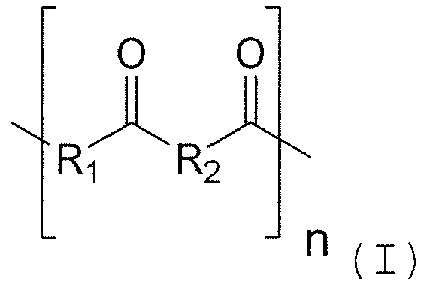
- Erfindungsgemäss wird die Barriere aus einem Polymer gebildet, welches Polyketone enthält oder aus Polyketonen besteht. Entsprechend umfasst die Polymerschicht Polyketone und Blends von Polyketonen sowie Laminate enthaltend Polyketone. Polyketone sind an sich bekannte Materialien und charakterisiert durch die Keto-Gruppe (C=O) in der Polymerkette. Polyketone umfassen somit Polymere, welche zu 50 - 100 Gew.%, bevorzugt zu 90-100 Gew.% Struktureinheiten der Formel (I) enthalten

- Der Begriff Polyketone umfasst die einfachen Polyketone (PK) in welchen R1 und R2 unabhängig voneinander jeweils für Alkyl (wie 1,2-Ethyl und 1,2-Propyl) steht. Einfache Polyketone sind durch katalytische Umsetzung von Kohlenmonoxid mit den entsprechenden Alkenen, wie Propen und/oder Ethen, erhältlich. Solche Polyketone sind bspw. unter dem Handelsnamen Akrotek kommerziell erhältlich. Solche einfachen Ketone werden auch als aliphatische Ketone bezeichnet.
- Der Begriff Polyketone umfasst ferner die Polyetherketone (PEK) in welchen R1 für Alkylether oder Arylether und R2 für Alkyl oder Aryl steht. Polyetherketone umfassen auch deren Derivate, wie PEEK, PEKK. In einer Ausführungsform umfasst der Begriff Polyetherketone in denen R1 für Arylether und R2 für oder Aryl steht solche Polyketone werden auch als aromatische Polyketone bezeichnet. Polyetherketone sind bspw. durch Umsetzung von bi-substituierten Alkyl- bzw. Arylketonen mit Diolen bzw. Biphenolen erhältlich. Solche Polyketone sind bspw. unter dem Handelsnamen Victrex kommerziell erhältlich.
- Der Begriff Alkyl steht insbesondere für unsubstituiertes C1-C4 Alkyl; der Begriff Aryl steht insbesondere für Phenyl und Naphtyl.
- Dem Fachmann sind auf Polyketonen basierende Polymere bekannt und diese sind Handelsprodukte. So stellt die koreanische Fa. Hyosung ein Basispolymer her. Es handelt sich um ein Terpolymer bestehend aus Ethylen, Propylen und Kohlenmonoxid oder ein Copolymer gebildet aus Ethylen und Kohlenmonoxid. Verschiedene Firmen verarbeiten dieses Basispolymer und bieten entsprechende Rezepturen in Form von Granulaten an, die dann in Extrusion oder Spritzguss weiterverarbeitet werden können. Es können die Firmen Ria-Polymers GmbH oder Akro-Plastik als Lieferanten genannt werden. Die vorstehend genannten aliphatischen Ketone haben sich als besser geeignet für das nachstellend beschriebene Herstellungsverfahren gezeigt und sind daher bevorzugt.
- Das Leitungsrohr kann ein Wellrohr sein oder kann ein starres gerades Rohrstück sein.
- Das Innenrohr kann aus polymerem Werkstoffen oder metallischem Werkstoffen, bevorzugt aus polymeren Werkstoffen bestehen. Solche Materialien sind an sich bekannt und umfassen insbesondere Polyolefine, wie vernetztes Polyethylen.
- Bevorzugt ist die Barriere eine Schicht, welche eine Dicke von 50 µm bis 300 µm aufweist. Die Barriere kann eine Dicke von 0,5 mm bis 5 mm aufweisen.
- Das Leitungsrohr ist bevorzugt so gebildet, dass das Polymer zu 50 - 100 Gew.%, bevorzugt zu 90-100 Gew.% Struktureinheiten der Formel (I) enthält

- worin R1 und R2 unabhängig voneinander für Alkyl, insbesondere Ethyl und Propyl steht oder
- worin R1 für Alkylether oder Arylether und R2 für Alkyl oder Aryl steht.
- Der Erfindung liegt weiter die Aufgabe zu Grunde, ein verbessertes Verfahren zur Herstellung eines Leitungsrohrs zu schaffen.
- Dies wird bei einem Verfahren zur Herstellung eines thermisch gedämmten Leitungsrohrs gemäss Anspruch 1 mit mindestens einem Innenrohr, einer Wärmedämmschicht und einem Aussenmantel, wobei
- das mindestens eine Innenrohr kontinuierlich von einem Vorrat abgezogen und mit einer zu einem Schlauch geformten Kunststofffolie umhüllt wird,
- in den Raum zwischen Innenrohr und Schlauch ein aufschäumbarer Kunststoff als Wärmedämmschicht eingebracht wird,
- das Innenrohr und der Schlauch in ein aus mitlaufenden Formteilen gebildetes Werkzeug eingebracht werden und dieses Werkzeug an dessen Ende verlassen, und danach
- auf die Oberfläche des Schlauches der Aussenmantel extrudiert wird,
- Es zeigt sich, dass ein so gebildetes Leitungsrohr die zuvor geschilderten Nachteile vermeidet.
- Bevorzugt wird die Barriere zwischen der aufgeschäumten Wärmedämmschicht und der Innenseite des Aussenmantels derart eingebracht, indem der Schlauch aus dem Polymer gebildet wird.
- In einer anderen Ausführung des Verfahrens wird die Barriere durch Coextrusion zusammen mit dem Aussenmantel aufgebracht. Dies kann so erfolgen, dass die Barriere direkt auf den Schlauch aufgebracht wird. In einer anderen Ausführung kann dies so erfolgen, dass zunächst eine Schicht des Aussenmantels, gefolgt durch die Barriere und gefolgt durch mindestens eine zweite Schicht des Aussenmantels aufgebracht wird.
- Das Verfahren kann so ausgeführt werden, dass zusätzlich eine Barriere, wie geschildert, in radialer Richtung nach der Wärmedämmung folgt.
- Der Erfindung liegt ferner die Aufgabe zu Grunde ein verbessertes diskontinuierliches Verfahren zu schaffen, welches die genannten Nachteile vermeidet.
- Dies erfolgt bei einem Verfahren zur Herstellung eines thermisch gedämmten Leitungsrohrs mit mindestens einem Innenrohr, einer Wärmedämmschicht und einem Aussenmantel, wobei ein Innenrohr innerhalb eines Aussenrohrs zentriert wird - was auf verschiedene an sich bekannte Weise erfolgen kann - und der Raum zwischen dem Innenrohr und dem Aussenrohr mit einem thermisch dämmenden, geschäumten Kunststoffmaterial gefüllt wird, insbesondere mit einem PU-Schaum gefüllt wird, dadurch, dass bei der Herstellung eine Barriere aus einem Polymer zwischen der aufgeschäumten Wärmedämmschicht und der Aussenseite des Aussenmantels eingebracht wird, welches Polymer Polyketone enthält oder aus Polyketonen besteht.
- Die Barriere kann an der Innenseite des Aussenrohrs aufgebracht werden. Insbesondere kann das Aussenrohr bereits bei seiner Herstellung mit einer solchen Barriere versehen worden sein. Die Barriere kann alternativ oder zusätzlich im Aussenrohr vorgesehen werden. Bevorzugt wird die Barriere als Schicht mit einer Dicke von 50 um bis 300 µm vorgesehen.
- Es kann auch vorgesehen sein, dass das Material des Aussenrohrs das Polymer enthält oder aus diesem besteht.
- Das Verfahren wird bevorzugt so durchgeführt, dass das Polymer zu 50 - 100 Gew.%, bevorzugt zu 90-100 Gew.% Struktureinheiten der Formel (I) enthält

- worin R1 und R2 unabhängig voneinander für Alkyl, insbesondere Ethyl und Propyl steht oder
- worin R1 für Alkylether oder Arylether und R2 für Alkyl oder Aryl steht.
- Es zeigt sich, dass eine Barriere mit oder aus Polyketonen gute Barriereeigenschaften gegen Stickstoff, Kohlendioxid, Treibmittel auf der Basis von Kohlenwasserstoffen (z.B. Cyclopentan) und gegen Hydrofluorolefine (HFO) aufweist. Eine solche Barriere erlaubt somit auch den Einsatz in Kombination mit derzeit noch nicht allgemein üblichen Wärmedämmschäumen. Ferner ist die Barriere gemäss der vorliegenden Erfindung auch bei hoher Luftfeuchtigkeit gut einsetzbar.
- Weitere Ausgestaltungen, Vorteile und Anwendungen der Erfindung ergeben sich aus den abhängigen Ansprüchen und aus der nun folgenden Beschreibung anhand der Figuren. Dabei zeigen:
-
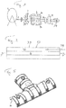
Figur 1 schematisch eine Vorrichtung zur kontinuierlichen Herstellung von thermisch gedämmten Rohren; -
Figur 2 zeigt schematisch die Herstellung von einzelnen starren thermisch gedämmten Rohrstücken; -
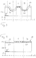
Figur 3 zeigt schematisch Beispiele für den Schichtaufbau eines thermisch gedämmten flexiblen Leitungsrohrs mit einer gewellten Form der Wärmedämmung und des Aussenmantels; -
Figur 4 zeigt schematisch Beispiele für den Schichtaufbau eines thermisch gedämmten starren Leitungsrohrs mit einem glatten Aussenmantel; und -
Figur 5 zeigt ein Formteil zur Abdeckung der Verbindung thermisch gedämmter Leitungsrohre. - In
Figur 1 ist die ausEP-0 897 788 A1 bekannte Anlage zur kontinuierlichen Herstellung von thermisch gedämmten Leitungsrohren dargestellt. Von einer Vorratsrolle 1 wird das Innenrohr 2 abgewickelt. Eine Kunststoff-Folie 5 wird von einem Vorrat 4 dem Innenrohr 2 zugeführt und zu einem Schlauch 6 mit einer verklebten oder verschweissten Längsnaht geformt, welcher sich um das Innenrohr legt. In den Raum zwischen Innenrohr 2 und Schlauch 6 wird ein aufschäumendes Kunststoffgemisch, vorzugsweise auf Polyurethanbasis, eingebracht, insbesondere mit einer Pistole 7. Das Innenrohr, der Schlauch und das aufschäumende Polyurethan werden einem Formwerkzeug 9 mit einer Vielzahl von Formhälften 9a und 9b zugeführt. Der Druck des PU-Schaums presst den Schlauch 6 gegen das Formwerkzeug und die von dem PU-Schaum gebildete thermische Dämmung nimmt die vom Formwerkzeug vorgegebene Form an, zum Beispiel eine gewellte Form, und tritt nach genügender Aushärtung im Formwerkzeug in dieser Form aus dem Formwerkzeug 9 aus. Es kann insbesondere auch eine glatte, insbesondere zylindrische Form ohne Wellung erzeugt werden. Auf das aus dem Formwerkzeug austretende Rohr 10 wird mittels eines Extruders 12 der Aussenmantel 13 aufextrudiert. Das fertige, thermisch gedämmte Wellrohr 14 kann auf Grund seiner Flexibilität auf Rollen aufgerollt werden. In einer ausWO 2010/085906 A1 bekannten Abwandlung des Verfahrens, wird nach dem Extrudieren des Aussenmantels eine Wellung in das Rohr 14 eingepresst. Diese Herstellungsarten sind bekannt und haben sich bewährt. - Die kontinuierliche Herstellung von glatten Rohren nach dem obigen Verfahren kann auch zur Bildung von geraden starren Rohren verwendet werden, welche in der gewünschten Länge vom kontinuierlich hergestellten, ungewellten Rohr abgelängt werden.
- Eine weitere Herstellart für starre gerade Rohre ist aus
WO 2010/127463 A1 bekannt, wobei das Innenrohr innerhalb des Aussenmantels durch Zug gerade gehalten und der Raum zwischen Innenrohr und Aussenmantel mittels mindestens einer manuell bedienten Schäumlanze ausgeschäumt wird.Figur 2 zeigt dieses bekannte Vorgehen grob schematisch im Längsschnitt mit dem Innenrohr 2, welches durch Zug, dargestellt durch die Pfeile F, innerhalb eines Aussenrohrs 33, welches den Aussenmantel 13 des fertigen Leitungsrohrs bildet, gerade gehalten wird. Mittels einer Schäumlanze 39 wird der Wärmedämmschaum in den Zwischenraum 40 zwischen den Rohren eingebracht. Die Zentrierung des Innenrohrs kann auch auf bekannte Weise durch Abstandshalter erfolgen anstelle der Zentrierung durch Zugkraft. Die erläuterten Vorgehensweisen sind dem Fachmann bekannt und werden hier nicht weiter erläutert. Wenn nachfolgend von der Herstellung von thermisch gedämmten Leitungsrohren gesprochen wird, so sind alle bekannten Herstellverfahren gemeint und umfasst. - Gemäss der vorliegenden Erfindung wird eine Barriere in das thermisch gedämmte Rohr eingebracht. Liegt diese in radialer Richtung gesehen ausserhalb der Wärmedämmung, so verhindert sie das Austreten von Gas aus dem Schaummaterial in die Umgebung und das Eintreten von Gas aus der Umgebung in das Schaummaterial. Die Barriere kann zusätzlich auch auf dem Innenrohr aufgebracht sein oder vom Innenrohr selber gebildet sein. In diesem Fall verhindert sie das Eindringen von aus dem Innenrohr diffundierendem (Wasser-) Dampf in die Wärmedämmung .
- Die Dicke der Barriereschicht kann in einem breiten Bereich variieren, geeignet sind Dicken von 30-3000 µm, bevorzugt 50-300 µm. Überraschend wurde gefunden, dass die o.g. Polyketone selbst bei diesen geringen Dicken eine für die Anwendung angemessene Barrierewirkung erzielen. Wird die Barriere vom Aussenmantel selber und/oder vom Innenrohr selber gebildet, so kann deren Dicke zum Beispiel im Bereich von 0,5 mm bis 5 mm liegen.
- Die Barriereschicht kann mit einem zusätzlichen Haftvermittler versehen werden. Bevorzugt ist die Barriereschicht jedoch frei von Haftvermittler. Wie eingangs erwähnt, ist es besonders vorteilhaft im Herstellungsverfahren der hier beschriebenen Leitungsrohre auf die Verwendung von Haftvermittlern zu verzichten.
- Bei der Herstellung eines Wellrohrs mit dem generellen Ablauf gemäss
Figur 1 kann dies so erfolgen, dass die Kunststoff-Folie 5, die zum Schlauch 6 geformt wird, eine Polyketone enthaltende oder aus Polyketonen bestehende Kunststoff-Folie ist. Damit entsteht die Barriere als eine vom Schlauch 6 gebildete Schicht, die den Polyurethanschaum umgibt. Das aus dem Formwerkzeug 9 austretende Rohr 10 ist bereits vor dem Extruder 12 mit der Barriere versehen und der Aussenmantel 13 wird auf die Barriere extrudiert. Dabei wird keine Haftvermittlerschicht benötigt, so dass der Aussenmantel 13 direkt auf die Barriere extrudiert werden kann. Das fertige Wellrohr 14 weist somit eine Barriereschicht auf, die zwischen dem Wärmedämmschaum und dem Aussenmantel liegt und mit Schaum und Mantel durch die Herstellung verbunden ist. - Wird auf die erläuterte Weise zunächst ein ungewelltes oder gewelltes Rohr erzeugt, in welches in einem nachfolgenden Schritt eine Wellung eingepresst wird, so ist die Barriere ebenfalls zwischen dem Wärmedämmschaum und dem Aussenmantel angeordnet.
- Werden auf die erläuterte Weise ungewellte starre Rohrabschnitte als thermisch gedämmte Leitungsrohre erzeugt, die von einem kontinuierlich hergestellten Leitungsrohr abgelängt werden, so ist auch bei diesen Leitungsrohren die Barriere zwischen der Wärmedämmung und dem Aussenmantel angeordnet.
- In allen Fällen können die Eigenschaften der Polyketone enthaltenden oder aus Polyketonen bestehenden Barriere, die bei diesen Beispielen eine durch die Folie gegebene Barriereschicht ist, durch die Wahl der Folie 5 bestimmt werden. Polyketon-Folien sind im Handel erhältlich, zum Beispiel von der Firma Lipp-Terler GmbH, Österreich. Bevorzugt ist eine Dicke der Barriere von 50 bis 300 µm. Entsprechend wird die Foliendicke gewählt.
- Alternativ oder zusätzlich kann bei den erläuterten kontinuierlichen Verfahren die Barriere beim Aufbringen des Aussenmantels 13 mittels des entsprechend für Coextrusion ausgeführten Extruders 12 erzeugt werden. In einer ersten Ausführung findet eine Coextrusion von mindestens drei Schichten und insbesondere von genau drei Schichten statt. Bei dieser Ausführung wird zunächst direkt auf die aus Dämmschaum und Folie 5 gebildete Wärmedämmung mindestens eine Schicht des Aussenmantelmaterials, insbesondere eine PE-Schicht aufgebracht. Darauf folgend, insbesondere direkt darauf folgend, ohne eine Haftvermittlerschicht, wird mindestens eine Schicht des Polyketone enthaltenden Polymers aufgebracht oder eine Schicht des aus Polyketonen bestehenden Polymers aufgebracht. Darauf folgt mindestens eine weitere Schicht des Aussenmantelmaterials, insbesondere des PE-Materials, und dies insbesondere direkt, ohne dass dazwischen eine Haftvermittlerschicht aufgebracht wird. In einer anderen Ausführung findet eine Coextrusion von mindestens zwei Schichten statt und insbesondere von genau zwei Schichten. Zunächst wird dabei die Barriere als Schicht des Polyketone enthaltenden Polymers oder eine Schicht des aus Polyketonen bestehenden Polymers direkt auf die Wärmedämmung (bzw. auf die Folie 5 der Wärmedämmung) aufgebracht, ohne dass zunächst ein anderes Aussenmantelmaterial aufgebracht wird und danach wird auf diese Barriere das Aussenmantelmaterial aufgebracht.
- Wird das Leitungsrohr als starres Leitungsrohrstück gemäss
Figur 2 hergestellt, so wird die Barriere bzw. die Schicht des Polyketone enthaltenden Polymers oder eine Schicht des aus Polyketonen bestehenden Polymers als innerste Schicht bzw. Innenwandung des Aussenrohrs 33 bei dessen Bildung durch Coextrusion hergestellt oder bei der Bildung des Aussenrohrs 33 durch Coextrusion wird die Barriere innerhalb des Aussenrohrs gebildet, so dass sie zwischen Schichten des Aussenrohrmaterial liegt, die z.B. PE-Schichten sind. Insbesondere liegt dann die Barriere direkt zwischen zwei PE-Schichten des Aussenrohrs 33, ohne dazwischenliegende Haftvermittlerschichten. In allen Fällen kann die Barriere zusätzlich von einer Schicht auf der Aussenseite des Innenrohrs 2 gebildet sein oder vom Innenrohr selber, wenn es aus dem Barrierematerial gebildet ist. Das Innenrohr kann bereits bei der Herstellung mit der Barriere versehen worden sein, so dass diese bereits bei dem auf der Rolle 1 befindlichen Innenrohr vorhanden ist. Die Barriere kann aber auch durch einen Extrusionsprozess oder einen Beschichtungsprozess durch Sprühen oder Tauchen zwischen der Rolle 1 und der Bildung des Folienschlauchs mit der Barriere versehen werden. Ferner kann die Barriere beim Innenrohr 2 vor der Bildung des Folienschlauchs auch derart aufgebracht werden, dass auf das Innenrohr eine Folie aus einem Polymer gewickelt wird, welches Polyketone enthält oder aus Polyketonen besteht. Die Barriere wird dann durch diese Folienlage gebildet, auf welche nachfolgend der Schaum der Wärmedämmung zu liegen kommt. Bei der Herstellung eines starren Rohrs durch Zentrierung eines Innenrohrs innerhalb eines Aussenrohrs (durch Abstandshalter oder durch Zugkraft, wie erläutert) kann das Innenrohr ebenfalls auf alle erwähnten Arten mit einer äusseren Barriere aus einem Polyketone enthaltenden oder aus Polyketonen bestehendem Polymer versehen werden, also zum Beispiel ebenfalls durch Umwickeln mit einer Folie, bevor das Innenrohr in dem Aussenrohr zentriert wird. Ebenso kann das Innenrohr aus dem Polymer bestehen. - Die
Figuren 3 und 4 zeigen jeweils grob schematisch einen Schnitt durch ein thermisch gedämmtes Leitungsrohr, wobei dieFigur 3 ein flexibles Wellrohr darstellen soll undFigur 4 ein glattes starres Rohr. Es ist jeweils nur der Teil des Schnitts oberhalb der Mittellängsachse L des Leitungsrohrs dargestellt. Die Darstellung ist grob schematisch und die gezeigten Elemente sind nicht massstäblich gezeigt. In beiden Figuren sind verschiedene Varianten der Barriere als Beispiele in den Bereichen A bzw. B bzw. C dargestellt. In einem realen Leitungsrohr ist natürlich entlang der Längsachse des Rohrs jeweils nur eine diese Varianten vorhanden oder allenfalls sind kumulativ mehrere der Varianten vorhanden, es ist aber nicht die Abfolge A, C, B vorhanden, wie in denFiguren 3 und 4 , wo dies nur zur vereinfachten Erläuterung verschiedener Beispiele so dargestellt ist. Zwischen den Bereichen A, B und C ist in den Figuren keine Barriere dargestellt. Das Innenrohr 2, welches ein Innenrohr aus Kunststoff oder Metall sein kann, ist von der Wärmedämmung 20 umgeben, welche insbesondere der zuvor erwähnte PU-Schaum ist. Über der Wärmedämmung 20 liegt der Aussenmantel 13, welcher ein gemässFigur 1 extrudierter Aussenmantel sein kann oder von dem zuvor hergestellten Rohr 33 gemässFigur 2 gebildet ist. - In
Figur 3 ist ein Wellrohr dargestellt und im Bereich A vonFigur 3 ist die Barriere 31 ersichtlich, welche, wie oben erläutert, so platziert worden ist, dass sie zwischen der Wärmedämmung 20 und dem Aussenmantel liegt. Dies kann so bewirkt worden sein, dass die Folie 5 bzw. der Schlauch 6 die Barriereeigenschaften hat. Oder es kann so bewirkt worden sein, dass die Extrusion des Aussenmantels mit der Extrusion einer Barriere begonnen hat oder dass das Rohr 33 innen die Barriere aufgewiesen hat. InFigur 4 ist diese Platzierung der Barriere 31 ebenfalls im Bereich A für ein glattes Leitungsrohr dargestellt. - Wird so vorgegangen, dass die Barriere während der Extrusion des Aussenmantels 13 durch den Extruder 12 oder bei der Herstellung des Rohrs 33 zwischen anderen Materialschichten des Aussenmantels bzw. des Rohrs 33 angeordnet wird, so ergibt sich die Situation wie sie im Bereich C des Leitungsrohrs der
Figuren 3 bzw. 4 dargestellt ist. Die Barriere 31 befindet sich innerhalb des Aussenmantels 13. Insbesondere liegt sie direkt zwischen zwei Schichten des Aussenmantelmaterials ohne zusätzliche Haftvermittlerschichten. Nicht dargestellt ist eine weitere Variante, bei welcher die Barriere die äusserste Schicht des Aussenmantels bildet, was ebenfalls möglich ist. Die Varianten der Bereiche A und B können auch kombiniert sein, so dass sowohl eine Barriere 31 auf der Wärmedämmung liegt als auch eine weitere Barriere 31 im Aussenmantel angeordnet ist. - Im Bereich C von
Figur 3 bzw. vonFigur 4 ist eine weitere Variante für die Bildung der Barriere angedeutet. In diesem Fall ist das Polyketone enthaltende Polymer oder das aus Polyketonen bestehende Polymer direkt zur Bildung des Aussenmantels 13 bzw. des Rohrs 33 verwendet worden. Die Barriere ist dann keine "Schicht" innerhalb des Aussenmantels aus anderem Material sondern wird vom Aussenmantel 13 selber gebildet. Insbesondere, wenn der Aussenmantel vollständig aus einem aus Polyketonen bestehenden Polymer gebildet wird, ergibt sich eine Barriere, die aus dem ganzen Aussenmantel besteht. In den Bereichen C ist dies durch die Symbole angedeutet, die im Aussenmantel eingezeichnet sind. - In
Figur 3 und Figur 4 ist in einem kurzen Abschnitt am linken Ende der Figuren eine Barriere 31' angedeutet, die auf dem Innenrohr liegt. Diese Barriere 31', aufgebracht als Schicht oder als Folienlage, kann vorhanden sein oder nicht und sie kann alleine vorgesehen sein oder mit allen Varianten der Barriere in radialer Richtung oberhalb der Wärmedämmung kombiniert sein, also mit den Varianten in den Bereichen A, B oder C. -
Figur 5 zeigt einen Teil 30 einer Abdeckungsvorrichtung aus Kunststoff, wie sie gemässWO 2008/019791 A1 bekanntermassen zum Umschliessen der Verbindungsstelle von thermisch gedämmten Leitungsrohren verwendet wird. An deren Verbindungsstelle sind die Leitungsrohre von der Wärmedämmung befreit worden, damit die jeweiligen Innenrohre verbunden werden konnten. Zur Wiederherstellung der thermischen Dämmung wird deshalb auf bekannte Weise ein PU-Schaum in die Abdeckungsvorrichtung eingebracht und füllt den Raum zwischen der Innenwand der Abdeckungsvorrichtung und den miteinander verbundenen Leitungsrohren. Es kann auch vorgesehen, dass eine Schicht des Polyketone enthaltenden Polymers oder eine Schicht des aus Polyketonen bestehenden Polymers an der Innenseite der Abdeckungsvorrichtung und/oder innerhalb des Materials der Abdeckungsvorrichtung vorgesehen ist so dass sich das Teil 30 gemässFigur 5 im Schnitt so darstellt, wie der Aussenmantel 13 mit der Barriere 30 im Bereich A vonFigur 4 oder wie der Aussenmantel mit der Barriere 30 im Bereich B vonFigur 4 . Die Abdeckungsvorrichtung kann auch aus einem Polyketone enthaltenden Polymer gebildet sein oder einem aus Polyketonen bestehenden Polymer gebildet sein, so dass sich das Teil gemässFigur 5 im Schnitt so darstellt, wie der Aussenmantel 13 im Bereich C vonFigur 4 . Anstelle einer Schale gemässFigur 5 kann auch eine Muffe zur an sich bekannten Verbindung von thermisch gedämmten Leitungsrohren vorgesehen sein. Auch die Muffe kann eine Barriere aus einem Polyketone enthaltendem Polymer aufweisen oder eine Barriere aus einem aus Polyketonen bestehendem Polymer. - Mit der Barriere gemäss der vorliegenden Erfindung, wird eine gute Barrierewirkung gegen die Gase der Luft (Sauerstoff und Stickstoff) und gegen die im PU-Schaum enthaltenen Gase, vor allem Kohlendioxid erzielt. Zudem ist diese Barriere bezüglich ihres Diffusionsverhaltens nicht stark abhängig von Feuchtigkeit. Ausserdem wird erzielt, dass die Barriere keine Haftvermittler benötigt um auf den relevanten Materialien wie PE zu haften. Ferner ist das Polyketone enthaltende oder aus Polyketonen bestehende Material nicht zu spröde, wodurch die Gefahr der Rissbildung bei mechanischer Beanspruchung gering ist.
- Während in der vorliegenden Anmeldung bevorzugte Ausführungen der Erfindung beschrieben sind, ist darauf hinzuweisen, dass die Erfindung nicht auf diese beschränkt ist und in auch anderer Weise innerhalb des Umfangs der folgenden Ansprüche ausgeführt werden kann.
- Die Erfindung wird anhand des nachfolgenden Beispiels näher erläutert.
- Gemessen wurde die Permeation von Sauerstoff, Stickstoff, Kohlendioxid und Wasserdampf durch handelsübliche Folien bestehend aus aliphatischen Polyketon.
- Zur Anwendung kamen Folien von zwei verschiedenen Herstellern, gekennzeichnet als PK1 und PK2, jeweils enthaltend >50 Gew.% aliphatische Polyketone der Formel (I). Die Folie PK1 mit einer Schichtdicke von 0.050 mm, die Folie PK2 mit einer Schichtdicke von 0.100 mm. Die angegeben Messergebnisse sind normiert auf die Schichtdicke von 0.050 mm. Die angegeben Messwerte sind der Durchschnitt aus zwei Einzelmessungen. Die Messung der Permeation von Sauerstoff und Stickstoff erfolgten gemäss der Norm ISO15105-2:2003, Annex A, 23 °C, 50 %r.F. Die Messung der Permeation von Kohlendioxid erfolgten gemäss der Norm ISO15105-2:2003, Annex A, 23 °C, 0 %r.F. Die Messung der Permeation von Wasserdampf erfolgte gemäss der Norm ISO15106-3:2005, 23 °C, 85 %r.F.
- Zum Vergleich dazu sind die Werte für gewöhnliches Polyethylen geringer Dichte angegeben. Diese Werte entnommen sind entnommen: PU Magazin, Dez/Jan 2005/2006, Jahrgang 05, S. 264-267, ebenfalls normiert auf eine Schichtdicke von 0.050 mm.
Tabelle 1: Permeation in cm3/m2*Tag*bar; normiert auf 0.050 mm Schichtdicke PK 1 PK 2 PE-LD gemäss Erfindung gemäss SdT Sauerstoff 12.9 19.8 4800 Stickstoff 7.50 6.60 1240 Kohlendioxid 298 120.6 16800 Wasserdampf 53.9 24.8 - Es zeigt sich, dass die Permeationswerte für aliphatisches Polyketon gemäss Folien PK1 und PK2 um Grössenordnungen besser sind.
Claims (15)
- Thermisch gedämmtes Leitungsrohr (14),
umfassend mindestens ein Innenrohr (2), mindestens eine um das Innenrohr herum angeordnete Wärmedämmung (20) und mindestens einen um die Wärmedämmung herum angeordneten Aussenmantel (13) sowie
umfassend mindestens eine Barriere aus Kunststoff, welche ein Polymer umfasst, das Polyketone enthält oder aus Polyketonen besteht
dadurch gekennzeichnet, dass die Barriere als Schicht, welche die Diffusion von Gasen aus der Wärmedämmung hinaus und in die Wärmedämmung hinein reduziert,(i) zwischen der Wärmedämmung und dem Aussenmantel angeordnet ist; oder(ii) im Aussenmantel angeordnet ist. - Leitungsrohr nach Anspruch 1, dadurch gekennzeichnet, dass das Polymer zu 50 - 100 Gew.%, bevorzugt zu 90-100 Gew.% Struktureinheiten der Formel (I) enthält

- Leitungsrohr nach Anspruch 1, dadurch gekennzeichnet, dass die Barriere
als Schicht auf der Wärmedämmung und/oder als Schicht auf der Innenseite des Aussenmantels angeordnet ist; oder
vom Aussenmantel gebildet wird. - Leitungsrohr nach einem der Ansprüche 1 bis 3,
dadurch gekennzeichnet, dass
das Leitungsrohr ein Wellrohr ist; oder
das Leitungsrohr ein starres gerades Rohrstück ist. - Leitungsrohr nach einem der Ansprüche 1 bis 4, dadurch gekennzeichnet, dass
die Barriere eine Schicht ist, welche eine Dicke von 50 µm bis 300 µm aufweist; oder
die Barriere vom Aussenmantel gebildet wird und eine Dicke von 0,5 mm bis 5 mm aufweist. - Leitungsrohr nach einem der Ansprüche 1 bis 5, dadurch gekennzeichnet, dass das Polymer zu 50 - 100 Gew.%, bevorzugt zu 90-100 Gew.% Struktureinheiten der Formel (I) enthält

- Verfahren zur Herstellung eines thermisch gedämmten Leitungsrohrs (14) gemäss Anspruch 1 mit mindestens einem Innenrohr, einer Wärmedämmschicht und einem Aussenmantel, wobei- das mindestens eine Innenrohr kontinuierlich von einem Vorrat abgezogen und mit einer zu einem Schlauch geformten Kunststofffolie umhüllt wird,- in den Raum zwischen Innenrohr und Schlauch ein aufschäumbarer Kunststoff als Wärmedämmschicht eingebracht wird,- das Innenrohr und der Schlauch in ein aus mitlaufenden Formteilen gebildetes Werkzeug eingebracht werden und dieses Werkzeug an dessen Ende verlassen, und danach- auf die Oberfläche des Schlauches der Aussenmantel extrudiert wird,dadurch gekennzeichnet, dass bei der Herstellung(A) eine Barriere aus einem Polymer zwischen der aufgeschäumten Wärmedämmschicht und der Aussenseite des Aussenmantels eingebracht wird, oder(B) dass der Aussenmantel aus dem Polymer gebildet wird oder(C) dass der Aussenmantel aus dem Polymer besteht;und wobei besagtes Polymer Polyketone enthält oder aus Polyketonen besteht.
- Verfahren nach Anspruch 7, dadurch gekennzeichnet, dass die Barriere zwischen der aufgeschäumten Wärmedämmschicht und der Innenseite des Aussenmantels eingebracht wird, indem der Schlauch aus dem Polymer gebildet wird.
- Verfahren nach Anspruch 7, dadurch gekennzeichnet, dass die Barriere durch Coextrusion zusammen mit dem Aussenmantel aufgebracht wird.
- Verfahren nach Anspruch 9, dadurch gekennzeichnet, dass die Barriere direkt auf den Schlauch aufgebracht wird.
- Verfahren nach Anspruch 9, dadurch gekennzeichnet, dass zunächst eine Schicht des Aussenmantels, gefolgt durch die Barriere und gefolgt durch mindestens eine zweite Schicht des Aussenmantels aufgebracht wird.
- Diskontinuierliches Verfahren zur Herstellung eines thermisch gedämmten Leitungsrohrs (14) nach Anspruch 1 mit mindestens einem Innenrohr, einer Wärmedämmschicht und einem Aussenmantel, wobei- ein Innenrohr innerhalb eines Aussenrohrs zentriert wird und- der Raum zwischen dem Innenrohr und dem Aussenrohr mit einem thermisch dämmenden, geschäumten Kunststoffmaterial gefüllt wird,dadurch gekennzeichnet, dass bei der Herstellung eine Barriere aus einem Polymer zwischen der aufgeschäumten Wärmedämmschicht und der Aussenseite des Aussenmantels eingebracht wird,
und wobei das Polymer Polyketone enthält oder aus Polyketonen besteht. - Verfahren nach Anspruch 12, dadurch gekennzeichnet,
dass die Barriere an der Innenseite des Aussenrohrs aufgebracht ist; und / oder.
dass die Barriere im Aussenrohr vorgesehen ist. - Verfahren nach Anspruch 12, dadurch gekennzeichnet, dass das Material des Aussenrohrs das Polymer enthält oder aus diesem besteht.
- Verfahren nach einem der Ansprüche 7 bis 14, dadurch gekennzeichnet, dass das Polymer zu 50 - 100 Gew.%, bevorzugt zu 90-100 Gew.% Struktureinheiten der Formel (I) enthält
Applications Claiming Priority (2)
| Application Number | Priority Date | Filing Date | Title |
|---|---|---|---|
| CH00181/15A CH710709A1 (de) | 2015-02-11 | 2015-02-11 | Leitungsrohr mit thermischer Dämmung. |
| PCT/CH2016/000027 WO2016127267A1 (de) | 2015-02-11 | 2016-02-09 | Leitungsrohr mit thermischer dämmung |
Publications (2)
| Publication Number | Publication Date |
|---|---|
| EP3256770A1 EP3256770A1 (de) | 2017-12-20 |
| EP3256770B1 true EP3256770B1 (de) | 2019-07-10 |
Family
ID=55409655
Family Applications (1)
| Application Number | Title | Priority Date | Filing Date |
|---|---|---|---|
| EP16705894.0A Active EP3256770B1 (de) | 2015-02-11 | 2016-02-09 | Leitungsrohr mit thermischer dämmung |
Country Status (4)
| Country | Link |
|---|---|
| EP (1) | EP3256770B1 (de) |
| CH (1) | CH710709A1 (de) |
| DK (1) | DK3256770T3 (de) |
| WO (1) | WO2016127267A1 (de) |
Families Citing this family (5)
| Publication number | Priority date | Publication date | Assignee | Title |
|---|---|---|---|---|
| DE202017007631U1 (de) | 2016-07-20 | 2023-10-27 | Brugg Rohr Ag Holding | Thermisch gedämmte Mediumrohre mit HFO - haltigem Zellgas |
| CH712779A1 (de) * | 2016-07-20 | 2018-01-31 | Brugg Rohr Ag Holding | Barriereschichten. |
| CH712780B1 (de) | 2016-07-20 | 2020-03-13 | Brugg Rohr Ag Holding | Thermisch gedämmte Mediumrohre mit HFO-haltigem Zellgas. |
| DE102018109210B4 (de) | 2018-04-18 | 2020-10-08 | German Pipe Industrie- und Fernwärmetechnik GmbH | Thermisch gedämmtes Rohr und Verfahren zu seiner Herstellung |
| RU2721373C1 (ru) * | 2019-12-14 | 2020-05-19 | Вадим Дмитриевич Зеленов | Подвеска транспортного средства с динамическим управлением наклоном колес и кузова в сторону поворота |
Family Cites Families (14)
| Publication number | Priority date | Publication date | Assignee | Title |
|---|---|---|---|---|
| DE3305216C2 (de) * | 1983-02-16 | 1986-04-10 | Westfalia Separator Ag, 4740 Oelde | Zentrifuge mit einer selbstentleerenden Schleudertrommel |
| US5499528A (en) * | 1994-09-26 | 1996-03-19 | W. L. Gore & Associates, Inc. | Apparatus for measuring hot gas content |
| DE19629678A1 (de) * | 1996-07-23 | 1998-01-29 | Brugg Rohrsysteme Gmbh | Verfahren zur Herstellung eines wärmeisolierten Leitungsrohres |
| DE20022368U1 (de) * | 2000-05-03 | 2001-09-06 | Rehau Ag + Co, 95111 Rehau | Rohr |
| DE10021523C2 (de) * | 2000-05-03 | 2003-05-28 | Rehau Ag & Co | Rohr |
| DK1355103T3 (en) | 2002-04-05 | 2019-01-28 | Logstor As | Preinsulated pipe |
| DE202006012463U1 (de) | 2006-08-12 | 2007-12-27 | Rehau Ag + Co. | Abdeckungsvorrichtung |
| WO2008113362A1 (en) * | 2007-03-16 | 2008-09-25 | Nkt Flexibles I/S | A flexible pipe |
| FR2917149B1 (fr) * | 2007-06-07 | 2011-03-11 | Tubest Flexible Solutions | Tubulure flexible a tuyau onduleux et protection mecanique externe |
| DE202008014092U1 (de) * | 2008-10-23 | 2010-03-11 | Rehau Ag + Co | Rohr |
| EP2213440A1 (de) | 2009-01-29 | 2010-08-04 | Brugg Rohr AG, Holding | Verfahren zur Herstellung eines wärmeisolierten Leitungsrohres |
| ES2568044T3 (es) | 2009-05-05 | 2016-04-27 | Brugg Rohr Ag, Holding | Procedimiento y dispositivo para la fabricación de una tubería aislada térmicamente |
| DE102010022354A1 (de) * | 2009-12-23 | 2011-06-30 | isoplus Fernwärmetechnik GmbH, 99706 | Kunststoffmantelrohr und Verfahren zu dessen Herstellung |
| GB2513759B (en) * | 2014-07-25 | 2015-05-13 | Thermaflue Systems Ltd | Improved safety shield for a pipe joint |
-
2015
- 2015-02-11 CH CH00181/15A patent/CH710709A1/de not_active Application Discontinuation
-
2016
- 2016-02-09 EP EP16705894.0A patent/EP3256770B1/de active Active
- 2016-02-09 DK DK16705894.0T patent/DK3256770T3/da active
- 2016-02-09 WO PCT/CH2016/000027 patent/WO2016127267A1/de not_active Ceased
Non-Patent Citations (1)
| Title |
|---|
| None * |
Also Published As
| Publication number | Publication date |
|---|---|
| DK3256770T3 (da) | 2019-10-14 |
| WO2016127267A1 (de) | 2016-08-18 |
| CH710709A1 (de) | 2016-08-15 |
| EP3256770A1 (de) | 2017-12-20 |
Similar Documents
| Publication | Publication Date | Title |
|---|---|---|
| EP0897788B1 (de) | Verfahren zur Herstellung eines wärmeisolierten Leitungsrohres | |
| DE69831870T2 (de) | Koaxialkabel und sein herstellungsverfahren | |
| CH653950A5 (de) | Verfahren zur herstellung eines waermeisolierten leitungsrohres. | |
| WO2016127267A1 (de) | Leitungsrohr mit thermischer dämmung | |
| EP3758910B1 (de) | Verfahren und vorrichtung zur herstellung eines wärmegedämmten leitungsrohrs | |
| EP3433093B1 (de) | Thermisch gedämmte mediumrohre mit hfo-haltigem zellgas | |
| EP3112124B1 (de) | Verfahren zur beschichtung einer rohrleitung | |
| DE202017007709U1 (de) | Klebstoff-Übertragungsschlauch mit einer Sperrschicht | |
| EP1471299B1 (de) | Wärmeisoliertes Leitungsrohr | |
| DE3530187C2 (de) | Verfahren und Vorrichtung zur Herstellung von thermisch isolierten Leitungsrohren | |
| EP2964996B1 (de) | Wärmegedämmtes gewelltes leitungsrohr | |
| EP1371469A2 (de) | Verfahren zur Herstellung eines wärmeisolierten Leitungsrohres | |
| EP2466185A1 (de) | Kunststoffverbundrohr, seine Verwendung und Verfahren zu seiner Herstellung | |
| DE3216463A1 (de) | Verfahren zum herstellen eines flexiblen fernwaermeleitungsrohres | |
| DE1289297B (de) | Verfahren und Vorrichtung zur kontinuierlichen Herstellung mehrschichtiger Schlaeuche aus thermoplastischen Kunststoffen nach dem Extrusionsverfahren | |
| DE2700478C2 (de) | Verfahren zur Herstellung eines wärme- und schallisolierten Leitungsrohres | |
| DE2338431C2 (de) | Verfahren zur Ummantelung eines länglichen Gegenstandes | |
| DE202014100764U1 (de) | Schrumpfmuffe mit Diffusionssperre | |
| EP1640652B1 (de) | Thermisch isoliertes, flexibles Leitungsrohr und Verfahren zur und Vorrichtung für die Herstellung eines Leitungsrohrs | |
| EP2431158A1 (de) | Verfahren zur Herstellung thermisch isolierter Rohre, insbesondere Kupferrohre | |
| DE102012211651A1 (de) | Verfahren zur Herstellung eines Wickelrohrs | |
| DE202017007631U1 (de) | Thermisch gedämmte Mediumrohre mit HFO - haltigem Zellgas | |
| EP4324632B1 (de) | Verfahren und herstellungsanlage zur herstellung eines wärmeisolierten leitungsrohrs | |
| DE3120719C2 (de) |
Legal Events
| Date | Code | Title | Description |
|---|---|---|---|
| STAA | Information on the status of an ep patent application or granted ep patent |
Free format text: STATUS: THE INTERNATIONAL PUBLICATION HAS BEEN MADE |
|
| PUAI | Public reference made under article 153(3) epc to a published international application that has entered the european phase |
Free format text: ORIGINAL CODE: 0009012 |
|
| STAA | Information on the status of an ep patent application or granted ep patent |
Free format text: STATUS: REQUEST FOR EXAMINATION WAS MADE |
|
| 17P | Request for examination filed |
Effective date: 20170904 |
|
| AK | Designated contracting states |
Kind code of ref document: A1 Designated state(s): AL AT BE BG CH CY CZ DE DK EE ES FI FR GB GR HR HU IE IS IT LI LT LU LV MC MK MT NL NO PL PT RO RS SE SI SK SM TR |
|
| AX | Request for extension of the european patent |
Extension state: BA ME |
|
| DAV | Request for validation of the european patent (deleted) | ||
| DAX | Request for extension of the european patent (deleted) | ||
| STAA | Information on the status of an ep patent application or granted ep patent |
Free format text: STATUS: EXAMINATION IS IN PROGRESS |
|
| 17Q | First examination report despatched |
Effective date: 20180928 |
|
| GRAP | Despatch of communication of intention to grant a patent |
Free format text: ORIGINAL CODE: EPIDOSNIGR1 |
|
| STAA | Information on the status of an ep patent application or granted ep patent |
Free format text: STATUS: GRANT OF PATENT IS INTENDED |
|
| INTG | Intention to grant announced |
Effective date: 20190322 |
|
| GRAS | Grant fee paid |
Free format text: ORIGINAL CODE: EPIDOSNIGR3 |
|
| GRAA | (expected) grant |
Free format text: ORIGINAL CODE: 0009210 |
|
| STAA | Information on the status of an ep patent application or granted ep patent |
Free format text: STATUS: THE PATENT HAS BEEN GRANTED |
|
| AK | Designated contracting states |
Kind code of ref document: B1 Designated state(s): AL AT BE BG CH CY CZ DE DK EE ES FI FR GB GR HR HU IE IS IT LI LT LU LV MC MK MT NL NO PL PT RO RS SE SI SK SM TR |
|
| REG | Reference to a national code |
Ref country code: GB Ref legal event code: FG4D Free format text: NOT ENGLISH |
|
| REG | Reference to a national code |
Ref country code: CH Ref legal event code: EP Ref country code: AT Ref legal event code: REF Ref document number: 1153951 Country of ref document: AT Kind code of ref document: T Effective date: 20190715 |
|
| REG | Reference to a national code |
Ref country code: DE Ref legal event code: R096 Ref document number: 502016005459 Country of ref document: DE |
|
| REG | Reference to a national code |
Ref country code: IE Ref legal event code: FG4D Free format text: LANGUAGE OF EP DOCUMENT: GERMAN |
|
| REG | Reference to a national code |
Ref country code: SE Ref legal event code: TRGR |
|
| REG | Reference to a national code |
Ref country code: DK Ref legal event code: T3 Effective date: 20191011 |
|
| REG | Reference to a national code |
Ref country code: NL Ref legal event code: MP Effective date: 20190710 |
|
| REG | Reference to a national code |
Ref country code: LT Ref legal event code: MG4D |
|
| PG25 | Lapsed in a contracting state [announced via postgrant information from national office to epo] |
Ref country code: NO Free format text: LAPSE BECAUSE OF FAILURE TO SUBMIT A TRANSLATION OF THE DESCRIPTION OR TO PAY THE FEE WITHIN THE PRESCRIBED TIME-LIMIT Effective date: 20191010 Ref country code: LT Free format text: LAPSE BECAUSE OF FAILURE TO SUBMIT A TRANSLATION OF THE DESCRIPTION OR TO PAY THE FEE WITHIN THE PRESCRIBED TIME-LIMIT Effective date: 20190710 Ref country code: PT Free format text: LAPSE BECAUSE OF FAILURE TO SUBMIT A TRANSLATION OF THE DESCRIPTION OR TO PAY THE FEE WITHIN THE PRESCRIBED TIME-LIMIT Effective date: 20191111 Ref country code: HR Free format text: LAPSE BECAUSE OF FAILURE TO SUBMIT A TRANSLATION OF THE DESCRIPTION OR TO PAY THE FEE WITHIN THE PRESCRIBED TIME-LIMIT Effective date: 20190710 Ref country code: BG Free format text: LAPSE BECAUSE OF FAILURE TO SUBMIT A TRANSLATION OF THE DESCRIPTION OR TO PAY THE FEE WITHIN THE PRESCRIBED TIME-LIMIT Effective date: 20191010 Ref country code: NL Free format text: LAPSE BECAUSE OF FAILURE TO SUBMIT A TRANSLATION OF THE DESCRIPTION OR TO PAY THE FEE WITHIN THE PRESCRIBED TIME-LIMIT Effective date: 20190710 |
|
| PG25 | Lapsed in a contracting state [announced via postgrant information from national office to epo] |
Ref country code: AL Free format text: LAPSE BECAUSE OF FAILURE TO SUBMIT A TRANSLATION OF THE DESCRIPTION OR TO PAY THE FEE WITHIN THE PRESCRIBED TIME-LIMIT Effective date: 20190710 Ref country code: LV Free format text: LAPSE BECAUSE OF FAILURE TO SUBMIT A TRANSLATION OF THE DESCRIPTION OR TO PAY THE FEE WITHIN THE PRESCRIBED TIME-LIMIT Effective date: 20190710 Ref country code: GR Free format text: LAPSE BECAUSE OF FAILURE TO SUBMIT A TRANSLATION OF THE DESCRIPTION OR TO PAY THE FEE WITHIN THE PRESCRIBED TIME-LIMIT Effective date: 20191011 Ref country code: RS Free format text: LAPSE BECAUSE OF FAILURE TO SUBMIT A TRANSLATION OF THE DESCRIPTION OR TO PAY THE FEE WITHIN THE PRESCRIBED TIME-LIMIT Effective date: 20190710 Ref country code: ES Free format text: LAPSE BECAUSE OF FAILURE TO SUBMIT A TRANSLATION OF THE DESCRIPTION OR TO PAY THE FEE WITHIN THE PRESCRIBED TIME-LIMIT Effective date: 20190710 |
|
| PG25 | Lapsed in a contracting state [announced via postgrant information from national office to epo] |
Ref country code: TR Free format text: LAPSE BECAUSE OF FAILURE TO SUBMIT A TRANSLATION OF THE DESCRIPTION OR TO PAY THE FEE WITHIN THE PRESCRIBED TIME-LIMIT Effective date: 20190710 |
|
| PG25 | Lapsed in a contracting state [announced via postgrant information from national office to epo] |
Ref country code: RO Free format text: LAPSE BECAUSE OF FAILURE TO SUBMIT A TRANSLATION OF THE DESCRIPTION OR TO PAY THE FEE WITHIN THE PRESCRIBED TIME-LIMIT Effective date: 20190710 Ref country code: PL Free format text: LAPSE BECAUSE OF FAILURE TO SUBMIT A TRANSLATION OF THE DESCRIPTION OR TO PAY THE FEE WITHIN THE PRESCRIBED TIME-LIMIT Effective date: 20190710 Ref country code: EE Free format text: LAPSE BECAUSE OF FAILURE TO SUBMIT A TRANSLATION OF THE DESCRIPTION OR TO PAY THE FEE WITHIN THE PRESCRIBED TIME-LIMIT Effective date: 20190710 Ref country code: IT Free format text: LAPSE BECAUSE OF FAILURE TO SUBMIT A TRANSLATION OF THE DESCRIPTION OR TO PAY THE FEE WITHIN THE PRESCRIBED TIME-LIMIT Effective date: 20190710 |
|
| PG25 | Lapsed in a contracting state [announced via postgrant information from national office to epo] |
Ref country code: CZ Free format text: LAPSE BECAUSE OF FAILURE TO SUBMIT A TRANSLATION OF THE DESCRIPTION OR TO PAY THE FEE WITHIN THE PRESCRIBED TIME-LIMIT Effective date: 20190710 Ref country code: SM Free format text: LAPSE BECAUSE OF FAILURE TO SUBMIT A TRANSLATION OF THE DESCRIPTION OR TO PAY THE FEE WITHIN THE PRESCRIBED TIME-LIMIT Effective date: 20190710 Ref country code: SK Free format text: LAPSE BECAUSE OF FAILURE TO SUBMIT A TRANSLATION OF THE DESCRIPTION OR TO PAY THE FEE WITHIN THE PRESCRIBED TIME-LIMIT Effective date: 20190710 |
|
| REG | Reference to a national code |
Ref country code: DE Ref legal event code: R097 Ref document number: 502016005459 Country of ref document: DE |
|
| PLBE | No opposition filed within time limit |
Free format text: ORIGINAL CODE: 0009261 |
|
| STAA | Information on the status of an ep patent application or granted ep patent |
Free format text: STATUS: NO OPPOSITION FILED WITHIN TIME LIMIT |
|
| 26N | No opposition filed |
Effective date: 20200603 |
|
| PG25 | Lapsed in a contracting state [announced via postgrant information from national office to epo] |
Ref country code: SI Free format text: LAPSE BECAUSE OF FAILURE TO SUBMIT A TRANSLATION OF THE DESCRIPTION OR TO PAY THE FEE WITHIN THE PRESCRIBED TIME-LIMIT Effective date: 20190710 |
|
| GBPC | Gb: european patent ceased through non-payment of renewal fee |
Effective date: 20200209 |
|
| REG | Reference to a national code |
Ref country code: BE Ref legal event code: MM Effective date: 20200229 |
|
| PG25 | Lapsed in a contracting state [announced via postgrant information from national office to epo] |
Ref country code: LU Free format text: LAPSE BECAUSE OF NON-PAYMENT OF DUE FEES Effective date: 20200209 Ref country code: MC Free format text: LAPSE BECAUSE OF FAILURE TO SUBMIT A TRANSLATION OF THE DESCRIPTION OR TO PAY THE FEE WITHIN THE PRESCRIBED TIME-LIMIT Effective date: 20190710 |
|
| PG25 | Lapsed in a contracting state [announced via postgrant information from national office to epo] |
Ref country code: IE Free format text: LAPSE BECAUSE OF NON-PAYMENT OF DUE FEES Effective date: 20200209 Ref country code: GB Free format text: LAPSE BECAUSE OF NON-PAYMENT OF DUE FEES Effective date: 20200209 |
|
| PG25 | Lapsed in a contracting state [announced via postgrant information from national office to epo] |
Ref country code: BE Free format text: LAPSE BECAUSE OF NON-PAYMENT OF DUE FEES Effective date: 20200229 |
|
| REG | Reference to a national code |
Ref country code: AT Ref legal event code: MM01 Ref document number: 1153951 Country of ref document: AT Kind code of ref document: T Effective date: 20210209 |
|
| PG25 | Lapsed in a contracting state [announced via postgrant information from national office to epo] |
Ref country code: AT Free format text: LAPSE BECAUSE OF NON-PAYMENT OF DUE FEES Effective date: 20210209 |
|
| PG25 | Lapsed in a contracting state [announced via postgrant information from national office to epo] |
Ref country code: MT Free format text: LAPSE BECAUSE OF FAILURE TO SUBMIT A TRANSLATION OF THE DESCRIPTION OR TO PAY THE FEE WITHIN THE PRESCRIBED TIME-LIMIT Effective date: 20190710 Ref country code: CY Free format text: LAPSE BECAUSE OF FAILURE TO SUBMIT A TRANSLATION OF THE DESCRIPTION OR TO PAY THE FEE WITHIN THE PRESCRIBED TIME-LIMIT Effective date: 20190710 |
|
| PG25 | Lapsed in a contracting state [announced via postgrant information from national office to epo] |
Ref country code: MK Free format text: LAPSE BECAUSE OF FAILURE TO SUBMIT A TRANSLATION OF THE DESCRIPTION OR TO PAY THE FEE WITHIN THE PRESCRIBED TIME-LIMIT Effective date: 20190710 |
|
| P01 | Opt-out of the competence of the unified patent court (upc) registered |
Effective date: 20230328 |
|
| REG | Reference to a national code |
Ref country code: CH Ref legal event code: U11 Free format text: ST27 STATUS EVENT CODE: U-0-0-U10-U11 (AS PROVIDED BY THE NATIONAL OFFICE) Effective date: 20260301 |
|
| PGFP | Annual fee paid to national office [announced via postgrant information from national office to epo] |
Ref country code: SE Payment date: 20260228 Year of fee payment: 11 |
|
| PGFP | Annual fee paid to national office [announced via postgrant information from national office to epo] |
Ref country code: DE Payment date: 20260303 Year of fee payment: 11 Ref country code: DK Payment date: 20260225 Year of fee payment: 11 |
|
| PGFP | Annual fee paid to national office [announced via postgrant information from national office to epo] |
Ref country code: FI Payment date: 20260228 Year of fee payment: 11 |
|
| PGFP | Annual fee paid to national office [announced via postgrant information from national office to epo] |
Ref country code: FR Payment date: 20260225 Year of fee payment: 11 Ref country code: IS Payment date: 20260130 Year of fee payment: 11 |
|
| PGFP | Annual fee paid to national office [announced via postgrant information from national office to epo] |
Ref country code: CH Payment date: 20260301 Year of fee payment: 11 |