EP3256619B2 - Use of a fixture comprising magnetic means for holding rotary symmetric workpieces - Google Patents
Use of a fixture comprising magnetic means for holding rotary symmetric workpieces Download PDFInfo
- Publication number
- EP3256619B2 EP3256619B2 EP16706999.6A EP16706999A EP3256619B2 EP 3256619 B2 EP3256619 B2 EP 3256619B2 EP 16706999 A EP16706999 A EP 16706999A EP 3256619 B2 EP3256619 B2 EP 3256619B2
- Authority
- EP
- European Patent Office
- Prior art keywords
- magnet
- workpiece
- magnetic
- holding
- fixture
- Prior art date
- Legal status (The legal status is an assumption and is not a legal conclusion. Google has not performed a legal analysis and makes no representation as to the accuracy of the status listed.)
- Active
Links
Images


Classifications
-
- C—CHEMISTRY; METALLURGY
- C23—COATING METALLIC MATERIAL; COATING MATERIAL WITH METALLIC MATERIAL; CHEMICAL SURFACE TREATMENT; DIFFUSION TREATMENT OF METALLIC MATERIAL; COATING BY VACUUM EVAPORATION, BY SPUTTERING, BY ION IMPLANTATION OR BY CHEMICAL VAPOUR DEPOSITION, IN GENERAL; INHIBITING CORROSION OF METALLIC MATERIAL OR INCRUSTATION IN GENERAL
- C23C—COATING METALLIC MATERIAL; COATING MATERIAL WITH METALLIC MATERIAL; SURFACE TREATMENT OF METALLIC MATERIAL BY DIFFUSION INTO THE SURFACE, BY CHEMICAL CONVERSION OR SUBSTITUTION; COATING BY VACUUM EVAPORATION, BY SPUTTERING, BY ION IMPLANTATION OR BY CHEMICAL VAPOUR DEPOSITION, IN GENERAL
- C23C14/00—Coating by vacuum evaporation, by sputtering or by ion implantation of the coating forming material
- C23C14/22—Coating by vacuum evaporation, by sputtering or by ion implantation of the coating forming material characterised by the process of coating
- C23C14/50—Substrate holders
- C23C14/505—Substrate holders for rotation of the substrates
-
- C—CHEMISTRY; METALLURGY
- C23—COATING METALLIC MATERIAL; COATING MATERIAL WITH METALLIC MATERIAL; CHEMICAL SURFACE TREATMENT; DIFFUSION TREATMENT OF METALLIC MATERIAL; COATING BY VACUUM EVAPORATION, BY SPUTTERING, BY ION IMPLANTATION OR BY CHEMICAL VAPOUR DEPOSITION, IN GENERAL; INHIBITING CORROSION OF METALLIC MATERIAL OR INCRUSTATION IN GENERAL
- C23C—COATING METALLIC MATERIAL; COATING MATERIAL WITH METALLIC MATERIAL; SURFACE TREATMENT OF METALLIC MATERIAL BY DIFFUSION INTO THE SURFACE, BY CHEMICAL CONVERSION OR SUBSTITUTION; COATING BY VACUUM EVAPORATION, BY SPUTTERING, BY ION IMPLANTATION OR BY CHEMICAL VAPOUR DEPOSITION, IN GENERAL
- C23C16/00—Chemical coating by decomposition of gaseous compounds, without leaving reaction products of surface material in the coating, i.e. chemical vapour deposition [CVD] processes
- C23C16/44—Chemical coating by decomposition of gaseous compounds, without leaving reaction products of surface material in the coating, i.e. chemical vapour deposition [CVD] processes characterised by the method of coating
- C23C16/458—Chemical coating by decomposition of gaseous compounds, without leaving reaction products of surface material in the coating, i.e. chemical vapour deposition [CVD] processes characterised by the method of coating characterised by the method used for supporting substrates in the reaction chamber
- C23C16/4581—Chemical coating by decomposition of gaseous compounds, without leaving reaction products of surface material in the coating, i.e. chemical vapour deposition [CVD] processes characterised by the method of coating characterised by the method used for supporting substrates in the reaction chamber characterised by material of construction or surface finish of the means for supporting the substrate
-
- C—CHEMISTRY; METALLURGY
- C23—COATING METALLIC MATERIAL; COATING MATERIAL WITH METALLIC MATERIAL; CHEMICAL SURFACE TREATMENT; DIFFUSION TREATMENT OF METALLIC MATERIAL; COATING BY VACUUM EVAPORATION, BY SPUTTERING, BY ION IMPLANTATION OR BY CHEMICAL VAPOUR DEPOSITION, IN GENERAL; INHIBITING CORROSION OF METALLIC MATERIAL OR INCRUSTATION IN GENERAL
- C23C—COATING METALLIC MATERIAL; COATING MATERIAL WITH METALLIC MATERIAL; SURFACE TREATMENT OF METALLIC MATERIAL BY DIFFUSION INTO THE SURFACE, BY CHEMICAL CONVERSION OR SUBSTITUTION; COATING BY VACUUM EVAPORATION, BY SPUTTERING, BY ION IMPLANTATION OR BY CHEMICAL VAPOUR DEPOSITION, IN GENERAL
- C23C16/00—Chemical coating by decomposition of gaseous compounds, without leaving reaction products of surface material in the coating, i.e. chemical vapour deposition [CVD] processes
- C23C16/44—Chemical coating by decomposition of gaseous compounds, without leaving reaction products of surface material in the coating, i.e. chemical vapour deposition [CVD] processes characterised by the method of coating
- C23C16/50—Chemical coating by decomposition of gaseous compounds, without leaving reaction products of surface material in the coating, i.e. chemical vapour deposition [CVD] processes characterised by the method of coating using electric discharges
-
- H—ELECTRICITY
- H01—ELECTRIC ELEMENTS
- H01J—ELECTRIC DISCHARGE TUBES OR DISCHARGE LAMPS
- H01J37/00—Discharge tubes with provision for introducing objects or material to be exposed to the discharge, e.g. for the purpose of examination or processing thereof
- H01J37/32—Gas-filled discharge tubes
- H01J37/32431—Constructional details of the reactor
- H01J37/32715—Workpiece holder
-
- H—ELECTRICITY
- H01—ELECTRIC ELEMENTS
- H01J—ELECTRIC DISCHARGE TUBES OR DISCHARGE LAMPS
- H01J2237/00—Discharge tubes exposing object to beam, e.g. for analysis treatment, etching, imaging
- H01J2237/32—Processing objects by plasma generation
- H01J2237/33—Processing objects by plasma generation characterised by the type of processing
- H01J2237/332—Coating
- H01J2237/3321—CVD [Chemical Vapor Deposition]
Definitions
- the patent relates to the use of fixtures comprising a magnet arrangement in order to hold workpieces made of materials which can be attracted by magnetic forces and a method that uses the magnetic fixtures in plasma assisted vacuum processes. Furthermore the patent relates to the use of the fixtures for holding workpieces for conducting vacuum plasma treatments on surfaces of the workpieces.
- fixtures according to the patent are particularly advantageous for holding workpieces which are to be coated with diamond like carbon (DLC) layers deposited by using plasma assisted chemical vapor deposition (PACVD), since the inventive use of fixtures allow avoiding the generation of undesirable side plasmas which typically negatively affect the characteristics of the DLC coatings formed on the workpiece surfaces.
- DLC diamond like carbon
- PSVD plasma assisted chemical vapor deposition
- the plasma assistance is widely used to treat surfaces of tools, components, automotive parts, consumer products or medical devices by e.g. plasma surface activation, plasma etching, or plasma-assisted coating deposition as well as nitriding.
- the deposition of amorphous carbon coatings typically involves several plasma assisted process steps, like substrate etching in non-reactive atmosphere and deposition of amorphous carbon by plasma assisted vacuum deposition in reactive or non-reactive atmosphere.
- Amorphous carbon coatings consisting of a disordered network of carbon atoms with a mixture of both sp 3 - and sp 2 -coordinated bonds, are commonly referred as diamond like carbon coatings or DLC.
- DLC diamond like carbon coatings
- those coatings can exhibit tailor-made physical, chemical or tribological properties for a huge range of industrial applications such as protective coatings on cutting and forming tools, wear and friction reducing components and parts in automotive industry, decorative applications, or corrosion and wear minimizing applications in biomedical or consumer products.
- DLC coatings including hydrogen-free (i.e. a-C coatings), hydrogenated or non-metal doped DLC (i.e. a-C:H coatings) or metal doped DLC (i.e. a-C:H:Me coatings), also tetrahedral amporhous carbon (i.e. ta-C coatings) can be found.
- deposition techniques can be used to synthesize the DLC coating of choice on a wide range of substrate materials.
- deposition methods such as physical vapor deposition (PVD) processes, chemical vapor deposition (CVD), pulsed laser deposition (PLD) or also cathodic arc evaporation (CAE) are known for deposition of carbon coatings, often with the aid of additional plasmas at the substrate surface during coating growth, which allows for lowering the deposition temperature and thus a broader range of substrate materials.
- the whole coating material or at least coating constituents are transferred from a target material in a predominantly direct line of sight towards the workpiece. This typically results in a geometric coating thickness dependence from the substrate/workpiece geometry and/or workpiece alignment towards the particle flow during growth, which is significantly different to CVD or plasma assisted CVD (PACVD) processes which can provide a more or less uniform thickness on all free surfaces.
- CVD plasma assisted CVD
- the substrates can be mounted in a deposition chamber by substrate holding means, referred as fixtures in the following, which all have in common to hold the substrate in an optimal position during deposition as well as during transfer into and from the deposition chamber.
- the fixtures are often required to perform a single-, two- or even three-fold rotation during the deposition process with respect to the main symmetry axis of the deposition chamber.
- EP1881086A1 A more sophisticated approach for mounting a high number of workpieces in an industrial batch coating machine is given in EP1881086A1 , where the use of magnetic fixtures for chain pins is disclosed. It is shown that rotary symmetric steel parts can be mounted on substrate holders that exhibit each one permanent magnet in direct contact with the base of the workpiece. The holding forces between the magnetic fixture and the chain pin are chosen high enough to keep the pins in a constant position perpendicular to the first rotation axis of the rotating fixture holder.
- fixtures comprising magnetic means according to the state of the art unfortunately results in the generation of undesirable side plasmas during plasma assisted vacuum processes where a plasma is activated at the surfaces of the workpiece to be treated and also at surfaces of fixture parts, such as e.g. during deposition of DLC coatings by means of PACVD.
- the objective of the invention is solved by the use of the fixture system according to claim 1 and the method of plasma treatment according to claim 6.
- the inventors had the idea of constructing a fixture system comprising magnetic means but arranged in such a manner that the magnetic forces between the magnetic fixture and the workpiece can be sufficiently high to hold the workpiece but at the same time with the least possible impact in the magnetic field along the main axis of the workpiece in order to avoid inhomogenous coating thicknesses and coating properties of the coated substrate resulting from inhomogenous plasma conditions (produced for example by generation of undesirable side plasmas) at the surface of the workpiece.
- fixtures to hold workpieces comprise magnetic means in order to fix the workpiece to the holder.
- magnetic means in order to fix the workpiece to the holder.
- the magnetic field of such magnetic means leak into the surrounding environment of the fixture.
- the magnetic field established by the magnetic means should not effect on plasma condition.
- the plasma tends to be instable in the presence of additional magnetic fields originating from the fixtures.
- the patent discloses a fixture system which is in particular advantageous for holding parts or workpieces to be treated by means of a plasma assisted vacuum process, in particular during deposition of diamond like carbon films by PACVD.
- rotary symmetric parts e.g. plungers, needles or pins
- the used fixture system uses a simple magnetic arrangement in order to hold the coated substrates without negatively affecting the plasma conditions at the substrate surface.
- the magnetic field is almost exclusively confined within the workpiece-magnet fixture contact zone and thus unintended side plasmas due to a magnetic leak are prevented in this region.
- This enables in particular for deposition of DLC coatings with Optimum adhesion, highest coating thickness and property homogeneity along the surface of the coated part.
- a magnetic arrangement is set up in such a way that, together with the workpiece inserted into the fixture, the magnetic field is confined within a closed loop established by magnetic and/or ferromagnetic materials.
- FIG. 1 A schematic drawing of a magnetic fixture in figure 1 represents the state of the art, where a permanent magnet 51 is assembled on a fixture base 2.
- the magnet 51 is surrounded in radial direction by a shell 5, whose purpose is not further defined in literature.
- Such fixtures can be typically loaded in a separate multi-fixture holder plate, which is not shown here.
- Such holder plates are usually arranged on top of each other and undergo a two-fold rotation in a common batch-type coating machine, as they are fixed on a rotating carousel with fixed transmission.
- the rotary motion of the two-fold rotating multi-fixture tree is used to rotate the individual magnetic fixtures by stroking a gear ring 3 with a so called "flicker finger".
- the coating thickness of the DLC coating is significantly higher at the top of the workpiece, in our example a pin, compared to the surface area that is closer to the contact zone of the magnet fixture. Also the mechanical properties of the DLC coating are significantly different along the main axis of the coated pin, which can lead to premature failure during application.
- the magnetic holding forces are sufficiently high to enable the positioning of the workpiece upright, meaning the main axis of the coated workpiece is pointing towards the top of the deposition chamber, thus 0°, or in other cases the main workpiece axis is inclined to an arbitrary angle between 0° and 180°, which means that the workpiece can be mounted headfirst.
- the strength of a magnetic field can be understood to scale with the gradient of the magnetic field lines. It is thus a preferred embodiment of the present invention that the magnetic field of the fixture-workpiece combination can be mostly confined within the workpiece and adjacent magnet assembly, which avoids unintended side plasmas during plasma assisted vacuum processes, in particular PACVD, and thus improves the coating thickness distribution and coating property homogeneity along the main axis of the workpiece.
- a solid non-magnetic spacer material 55 as schematically indicated in Figure 3 , radially separates the permanent magnet 51 from the magnet yoke 6.
- the polarities of the magnets 51 can deviate from the orientation shown in Figures 2 and 3 , respectively, and has to be optimized for the individual plasma assisted vacuum process (e.g. in terms of the workpiece-fixture geometry, used materials, fixture and rotation concept).
- the non-magnetic spacer is preferably made of non-magnetic steel, as for instance 1.4301 or 1.4305, but can also be produced of non-magnetic ceramic material or a non-magnetic polymer.
- the magnet yoke 6 is preferably made of a ferromagnetic material, such as ferritic steel (e.g. 1.0718).
- the fixture base 2 is made of stainless, or austenitic, steel.
- the fixture base can also be made of ferritic steel or cast iron, which however requires a careful adaption of the overall magnetic concept of the magnet fixture, fixture mount at the carousel etc., as described below.
- the quantitative measurement of a magnetic field is difficult and depends on many factors, like. e.g. the geometry of workpiece, fixture and magnet assembly, as well as the used material combination of workpiece, magnets and other fixture parts, and the measurement method itself. Hence, the inventors believe that the local measured Gauss-value is not suitable to exactly define the claims of the invention.
- the characteristics of the coated and/or treated article can be used. Additionally the following embodiment should be regarded as particularly important. It is thus a preferred embodiment of the invention that the geometric relationship between magnet 51, air gap 53 and magnet yoke 6 has to be chosen in a way that the magnetic field is mostly confined within the workpiece-fixture combination so that following conditions are fulfilled:
- the air gap 53 ensures an equal distance between the magnet 51 and the yoke 6 radially and axially along the symmetry axis of the permanent magnet 51.
- a contact between magnet and yoke has to be enabled at the bottom side of the magnet in direction away from the workpiece.
- the magnetic yoke encloses the permanent magnet only circumferentially but not in direction towards the workpiece.
- the magnetic field lines thus enter the workpiece at the bottom side of the workpiece, at the contact zone of workpiece-fixture, and also preferably exit at the bottom side in order to create a closed loop of magnetic field lines with the magnet yoke.
- Figure 4 shows the setup used according to the present invention.
- a magnet In order to fix a substrate or part or workpiece 1 on fixtures during deposition, a magnet is needed and the magnet has to be submerged in a non- magnetic cover. As it is better not to detect any magnet field at the outside of the magnet protecting cover 4 except the top face which is in direction towards the work- piece. So it is better to adjust the magnet assembly in a way that a closed loop of magnet lines is created within the combination fixture-workpiece.
- a closed loop of magnet lines can be realized if magnets have to be arranged in opposite directions from their neighbored magnets and a magnet link plate (magnetic substance) is placed underneath the magnets.
- the quantity of arranged magnets has to be of even number.
- the present invention is very advantageous as undesirable side plasmas are avoided. Such undesirable side plasmas typically negatively affect the characteristics of the DLC coatings.
- FIG. 4 shows the magnet assembly according to the description above.
- the magnetic fixture is composed of a plurality of permanent magnets 61, which are submerged in the non-magnetic cover 4 and positioned on a magnet link plate 63.
- the permanent magnets are arranged pairwise with opposite magnetic polarities, as visible along the cross-section line A-A in the schematic drawing of 4.
- a good magnetic confinement of the magnetic field can be achieved within the magnetic fixture and the workpiece and simultaneously the magnetic field lines preferably expand only in vertical direction towards the workpiece and towards the magnetic link plate and exhibit thus a magnetic "closed loop".
- the geometric relationship between magnets 61, the arrangement of alternating polarities of adjacent magnets, the magnet link plate 63, has to be chosen in a way that the magnetic field is mostly confined within the workpiece-fixture combination so that following conditions are fulfilled:
- the used magnetic fixture is covered by a non-magnetic cover, preferably made of a corrosion resistant material such as stainless steel (e.g. 1.4301, 1.4305), that shields the magnet assembly from being coated during deposition and effectively protects the magnet assembly during chemical and/or mechanical cleaning.
- a corrosion resistant material such as stainless steel (e.g. 1.4301, 1.4305)
- the permanent magnets are made of strong hard magnetic material as e.g. Samarium-Cobalt alloy (SmCo) or the like.
- the used permanent magnets exhibit a Curie-Temperature of higher than 450°C in order to maintain the magnetic forces during a plasma assisted vacuum process.
- This high Curie-Temperature has the advantage that at lower process temperatures, in particular during deposition of DLC at e.g. 250 - 300 °C, the magnetic holding forces are more or less constant.
- the magnet link plate is made of steel (i.e. 1.4034) or any comparable magnetic material that allows for a magnetic link.
- the permanent magnets are arranged adjacent to each other but with alternate polarities. Further the set of magnets used have to be of even number, e.g. 2, 4, etc.
- a further preferred embodiment of the present invention is that the coating thickness distribution of the coated parts is within a range of 20 % of the average thickness of the coating along the mantle surface of the workpiece.
- the mantle surface hereby is defined as the surface of the workpiece along the main rotation axis of the workpiece.
- the magnetic fixtures can undergo a three-fold rotation with respect to the main axis of the deposition chamber. This achieved that the two-fold rotation of the multi-fixture holder passively triggers the individual three-fold rotation of the individual magnetic fixtures by stroking the gear ring 3 with fixed "flicker fingers".
- an additional transmission assembly can be used to achieve a three-fold rotation of the magnetic fixtures at a fixed rotation speed. In this case the gear ring 3 is used to rotate the magnetic fixtures in a controlled and continuous manner.
- the radial dimension of the magnet assemblies should be in total equal or slightly less than the radial dimension of the rotary symmetric workpiece. It is thus a preferred embodiment the outer radius of the magnet yoke should be in the range of 100 % to 50 % of the radial dimension of the workpiece.
- the inner radius of the magnet yoke, as well as the thickness of the air gap, or non-magnetic spacer, respectively, is defined by its functionality as described above.
- the outer radius of the magnet yoke or magnet pairs should be at maximum 10 mm and at minimum 5 mm.
- the magnet assembly can be used in any sort of reactive or non-reactive plasma assisted vacuum process, in particular treatments like etching, nitriding, carburizing, or coating deposition processes, where a plasma is active at the workpiece surface and side plasmas are unintended.
- a method according to any of the embodiments described above comprising a coating step, in which the workpieces are coated with a coating layer exhibiting a layer thickness variation of equal or less than 20% compared to the mean coating layer thickness measured at the mantle surface of the workpiece.
- a method according to any of the embodiments described above comprising a coating step, in which the workpieces are coated with a coating layer exhibiting a layer hardness variation of equal or less than 20% compared to the mean coating layer hardness measured at the mantle surface of the workpiece.
Landscapes
- Chemical & Material Sciences (AREA)
- Engineering & Computer Science (AREA)
- Chemical Kinetics & Catalysis (AREA)
- Materials Engineering (AREA)
- Mechanical Engineering (AREA)
- Metallurgy (AREA)
- Organic Chemistry (AREA)
- Physics & Mathematics (AREA)
- General Chemical & Material Sciences (AREA)
- Plasma & Fusion (AREA)
- Analytical Chemistry (AREA)
- Chemical Vapour Deposition (AREA)
- Physical Vapour Deposition (AREA)
- Electromagnetism (AREA)
- Power Engineering (AREA)
- Drying Of Semiconductors (AREA)
Description
- The patent relates to the use of fixtures comprising a magnet arrangement in order to hold workpieces made of materials which can be attracted by magnetic forces and a method that uses the magnetic fixtures in plasma assisted vacuum processes. Furthermore the patent relates to the use of the fixtures for holding workpieces for conducting vacuum plasma treatments on surfaces of the workpieces.
- The use of fixtures according to the patent are particularly advantageous for holding workpieces which are to be coated with diamond like carbon (DLC) layers deposited by using plasma assisted chemical vapor deposition (PACVD), since the inventive use of fixtures allow avoiding the generation of undesirable side plasmas which typically negatively affect the characteristics of the DLC coatings formed on the workpiece surfaces.
- Among the huge variety of reactive and non-reactive plasma processes, the plasma assistance is widely used to treat surfaces of tools, components, automotive parts, consumer products or medical devices by e.g. plasma surface activation, plasma etching, or plasma-assisted coating deposition as well as nitriding.
- As one example the deposition of amorphous carbon coatings typically involves several plasma assisted process steps, like substrate etching in non-reactive atmosphere and deposition of amorphous carbon by plasma assisted vacuum deposition in reactive or non-reactive atmosphere.
- Amorphous carbon coatings, consisting of a disordered network of carbon atoms with a mixture of both sp3- and sp2-coordinated bonds, are commonly referred as diamond like carbon coatings or DLC. Depending on their predominant bonding character, those coatings can exhibit tailor-made physical, chemical or tribological properties for a huge range of industrial applications such as protective coatings on cutting and forming tools, wear and friction reducing components and parts in automotive industry, decorative applications, or corrosion and wear minimizing applications in biomedical or consumer products. Among the different DLC coatings, including hydrogen-free (i.e. a-C coatings), hydrogenated or non-metal doped DLC (i.e. a-C:H coatings) or metal doped DLC (i.e. a-C:H:Me coatings), also tetrahedral amporhous carbon (i.e. ta-C coatings) can be found.
- In order to achieve optimal results during application, various deposition techniques can be used to synthesize the DLC coating of choice on a wide range of substrate materials. Typically deposition methods such as physical vapor deposition (PVD) processes, chemical vapor deposition (CVD), pulsed laser deposition (PLD) or also cathodic arc evaporation (CAE) are known for deposition of carbon coatings, often with the aid of additional plasmas at the substrate surface during coating growth, which allows for lowering the deposition temperature and thus a broader range of substrate materials.
- In most PVD processes, such as CAE, PLD or Sputtering, the whole coating material or at least coating constituents are transferred from a target material in a predominantly direct line of sight towards the workpiece. This typically results in a geometric coating thickness dependence from the substrate/workpiece geometry and/or workpiece alignment towards the particle flow during growth, which is significantly different to CVD or plasma assisted CVD (PACVD) processes which can provide a more or less uniform thickness on all free surfaces.
- In general the substrates can be mounted in a deposition chamber by substrate holding means, referred as fixtures in the following, which all have in common to hold the substrate in an optimal position during deposition as well as during transfer into and from the deposition chamber. Depending on workpiece size and shape, coating material, and deposition parameters, the fixtures are often required to perform a single-, two- or even three-fold rotation during the deposition process with respect to the main symmetry axis of the deposition chamber.
- While in some of the above mentioned plasma assisted vacuum process techniques the presence of the plasma at the workpiece is of subordinated importance, in PACVD the plasma conditions at the substrate surface of the workpiece to be coated become of major importance to reach good adhesion, homogenous coating properties, and thicknesses throughout the substrate surface. Especially for precision components or automotive parts with rotary symmetry along the main axis of the workpiece, such as e.g. needles, pins or plungers, a high uniformity of coating properties is inevitably necessary to achieve optimum results during application. For this reason the substrate mount becomes a crucial part of the overall process assembly in e.g. DLC coating processes, where plasmas are active at the tools or substrate surface during etching as well as the deposition process itself
- In many cases it is sufficient to use clamps, hooks or plate/cup-shaped fixtures to mount the workpiece in the deposition chamber and enable for substrate rotation as explained above. However shadowing effects in the vicinity of the contact zone between the mechanical substrate holder and the workpiece surface can lead to inhomogeneities of coating thicknesses and coating properties which has to be avoided wherever possible.
- Recently, the use of two-fold rotating magnetic holders has been disclosed in
US8152971 B2 for mounting cemented carbide inserts. This approach enables for small contact zones between the workpiece and the substrate holder and avoids the mechanical interaction and thus shadowing effects at the functional surface of the coated part. As described inUS8152971 B2 the magnetic field enhancement at corners and edges was further found to increase the coating thickness at edges and corners of the cutting tools, which enabled for higher tool lifetime in turning operations. Unfortunately, such magnetic fixtures with undefined magnetic field lines are not suitable for deposition of DLC by PACVD processes on high-end automotive parts and precision components as the inhomogenous magnetic field of the substrate mount would lead to inhomogenous plasma conditions over the workpiece surface. Especially if the workpieces exhibit rotary symmetry and highest accuracy in terms of coating thickness distribution and homogenous coating properties over the surface of the coated parts this approach cannot meet the requirements. - A more sophisticated approach for mounting a high number of workpieces in an industrial batch coating machine is given in
EP1881086A1 , where the use of magnetic fixtures for chain pins is disclosed. It is shown that rotary symmetric steel parts can be mounted on substrate holders that exhibit each one permanent magnet in direct contact with the base of the workpiece. The holding forces between the magnetic fixture and the chain pin are chosen high enough to keep the pins in a constant position perpendicular to the first rotation axis of the rotating fixture holder. This approach however results in an inhomogenous magnetic field along the main axis or rotation axis of the pins due to the fact that the magnetic field lines expand from the magnetic south pole of the permanent magnet and "enter" at the base of the part throughout the workpiece and will find their end in the magnetic north pole, which is located on the opposite side of the contact zone between pin and fixture. This creates an "open" magnetic field over the workpiece and the magnetic fixture holder, which can be referred as magnetic leak and will inherently result in detrimental inhomogeneities of the magnetic field distribution and thus the surrounding plasma conditions along the workpiece axis. - The use of the above mentioned fixtures comprising magnetic means according to the state of the art unfortunately results in the generation of undesirable side plasmas during plasma assisted vacuum processes where a plasma is activated at the surfaces of the workpiece to be treated and also at surfaces of fixture parts, such as e.g. during deposition of DLC coatings by means of PACVD.
- It is thus necessary to find a solution for avoiding generation of undesirable side plasmas during the conduction of plasma assisted vacuum processes, where a reactive or non-reactive plasma is active at the substrate surface in order to accomplish a homogenous treatment of the surface of the workpiece as well as production of coatings having homogeneous properties along the complete coated surfaces independent from the distance between the contact zone of the substrate to be coated and the holding fixture.
- Another, not yet mentioned, requirement for the fixture is the stability against corrosive and abrasive media because of inevitable regular cleaning cycles of industrial coating equipment. This is often performed by sand blasting of the coated fixtures and/or wet chemical cleaning in aggressive media.
- The objective of the invention is solved by the use of the fixture system according to
claim 1 and the method of plasma treatment according toclaim 6. The inventors had the idea of constructing a fixture system comprising magnetic means but arranged in such a manner that the magnetic forces between the magnetic fixture and the workpiece can be sufficiently high to hold the workpiece but at the same time with the least possible impact in the magnetic field along the main axis of the workpiece in order to avoid inhomogenous coating thicknesses and coating properties of the coated substrate resulting from inhomogenous plasma conditions (produced for example by generation of undesirable side plasmas) at the surface of the workpiece. - As already mentioned above quite often fixtures to hold workpieces comprise magnetic means in order to fix the workpiece to the holder. For some applications however it has to be avoided that the magnetic field of such magnetic means leak into the surrounding environment of the fixture. For example in the context of PVD or PACVD the magnetic field established by the magnetic means should not effect on plasma condition.
- Especially as fixtures are typically moving within the coating chamber during deposition in order to establish a homogeneous coating, the plasma tends to be instable in the presence of additional magnetic fields originating from the fixtures.
- The patent discloses a fixture system which is in particular advantageous for holding parts or workpieces to be treated by means of a plasma assisted vacuum process, in particular during deposition of diamond like carbon films by PACVD. Especially rotary symmetric parts (e.g. plungers, needles or pins), are in the focus of the current invention as the used fixture system uses a simple magnetic arrangement in order to hold the coated substrates without negatively affecting the plasma conditions at the substrate surface. Thereby the magnetic field is almost exclusively confined within the workpiece-magnet fixture contact zone and thus unintended side plasmas due to a magnetic leak are prevented in this region. This enables in particular for deposition of DLC coatings with Optimum adhesion, highest coating thickness and property homogeneity along the surface of the coated part.
- According to the solution of the present invention, a magnetic arrangement is set up in such a way that, together with the workpiece inserted into the fixture, the magnetic field is confined within a closed loop established by magnetic and/or ferromagnetic materials.
- The present invention and preferred embodiments of the present invention will be explained in the following and exemplarily supported by figures. The following explanations and examples are not intended to limit the present invention but only to help to understand the invention and to show ways in which the invention can be put into practice.
-
Figure 1 shows the setup of a fixture as commonly used today. With this setup the magnetic field is leaking into the neighborhood of the fixture and negatively affecting the plasma used during vapor deposition. -
Figure 2 shows one example of a magnetic fixture with amagnetic yoke 6 andair gap 53 between thepermanent magnet 51 and thenon-magnetic cover 4. -
Figure 3 shows one example of a magnetic fixture with amagnetic yoke 6 and anon-magnetic spacer 55 between thepermanent magnet 51 and thenon-magnetic cover 4. -
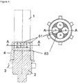
Figure 4 shows an example of a magnetic fixture with severalpermanent magnets 61 on amagnet link plate 63 inside thenon-magnetic cover 4. - A schematic drawing of a magnetic fixture in
figure 1 represents the state of the art, where apermanent magnet 51 is assembled on afixture base 2. Themagnet 51 is surrounded in radial direction by ashell 5, whose purpose is not further defined in literature. Such fixtures can be typically loaded in a separate multi-fixture holder plate, which is not shown here. Such holder plates are usually arranged on top of each other and undergo a two-fold rotation in a common batch-type coating machine, as they are fixed on a rotating carousel with fixed transmission. In order to achieve a three-fold rotation, the rotary motion of the two-fold rotating multi-fixture tree is used to rotate the individual magnetic fixtures by stroking agear ring 3 with a so called "flicker finger". - By using a magnetic fixture assembly as schematically shown in
Figure 1 , the coating thickness of the DLC coating is significantly higher at the top of the workpiece, in our example a pin, compared to the surface area that is closer to the contact zone of the magnet fixture. Also the mechanical properties of the DLC coating are significantly different along the main axis of the coated pin, which can lead to premature failure during application. - This negative implications of existing magnetic holders on plasma assisted vacuum processes can be overcome by using the proposed magnetic assemblies, in particular for the deposition of DLC coatings as explained in the following.
- The inventors surprisingly found that a significantly lower magnetic field around the workpiece-fixture contact zone is created, while maintaining sufficiently high magnetic holding forces to carry a
workpiece 1, if amagnet yoke 6 is installed in the magnet fixture radially separated from thepermanent magnet 51 by anair gap 53. A schematic drawing of such an assembly is presented inFigure 2 , where also anon-magnetic cover 4 of the magnet fixture is indicated. - First tests using a DLC coating process in an Oerlikon Balzers deposition plant have indicated that the homogeneity of the coating properties and thicknesses, as well as adhesion of the DLC coating can significantly be improved compared to a state-of-the-art magnet fixture. It was found that the utilization of a state-of-the-art magnet fixture, that creates a magnetic leak at the contact zone workpiece-fixture, exhibits a coating thickness difference of more than 40 % between the thickness of the mantle surface in the topmost region of the workpiece compared to the thickness at the workpiece region closest to the contact zone workpiece-fixture. If the magnet assembly is used in the magnet fixture, a significantly more homogenous distribution of coating thickness with only a variation of equal or less than 20% can be achieved.
- The magnetic holding forces are sufficiently high to enable the positioning of the workpiece upright, meaning the main axis of the coated workpiece is pointing towards the top of the deposition chamber, thus 0°, or in other cases the main workpiece axis is inclined to an arbitrary angle between 0° and 180°, which means that the workpiece can be mounted headfirst.
- The strength of a magnetic field can be understood to scale with the gradient of the magnetic field lines. It is thus a preferred embodiment of the present invention that the magnetic field of the fixture-workpiece combination can be mostly confined within the workpiece and adjacent magnet assembly, which avoids unintended side plasmas during plasma assisted vacuum processes, in particular PACVD, and thus improves the coating thickness distribution and coating property homogeneity along the main axis of the workpiece.
- A solid
non-magnetic spacer material 55, as schematically indicated inFigure 3 , radially separates thepermanent magnet 51 from themagnet yoke 6. - The polarities of the
magnets 51 can deviate from the orientation shown inFigures 2 and3 , respectively, and has to be optimized for the individual plasma assisted vacuum process (e.g. in terms of the workpiece-fixture geometry, used materials, fixture and rotation concept). - The non-magnetic spacer is preferably made of non-magnetic steel, as for instance 1.4301 or 1.4305, but can also be produced of non-magnetic ceramic material or a non-magnetic polymer.
- As an embodiment of the current invention the
magnet yoke 6 is preferably made of a ferromagnetic material, such as ferritic steel (e.g. 1.0718). - Another embodiment of the invention is that the
fixture base 2 is made of stainless, or austenitic, steel. Alternatively the fixture base can also be made of ferritic steel or cast iron, which however requires a careful adaption of the overall magnetic concept of the magnet fixture, fixture mount at the carousel etc., as described below. - The quantitative measurement of a magnetic field is difficult and depends on many factors, like. e.g. the geometry of workpiece, fixture and magnet assembly, as well as the used material combination of workpiece, magnets and other fixture parts, and the measurement method itself. Hence, the inventors believe that the local measured Gauss-value is not suitable to exactly define the claims of the invention.
- In order to properly describe the intended use of the magnet fixture, as well as the corresponding method using the fixture, the characteristics of the coated and/or treated article can be used. Additionally the following embodiment should be regarded as particularly important. It is thus a preferred embodiment of the invention that the geometric relationship between
magnet 51,air gap 53 andmagnet yoke 6 has to be chosen in a way that the magnetic field is mostly confined within the workpiece-fixture combination so that following conditions are fulfilled: - The magnetic field strength is sufficiently high to fix the workpiece,
- the magnetic field outside the workpiece is limited in a way that no undesired side plasma is active during plasma treatment and/or deposition,
- the magnet yoke material is not magnetically saturated.
- The same geometric/magnetic relationship applies mutatis mutandis for the situation with
magnet yoke 6 andnon-magnetic spacer 55. - It is also a preferred embodiment of the current invention that the
air gap 53 ensures an equal distance between themagnet 51 and theyoke 6 radially and axially along the symmetry axis of thepermanent magnet 51. A contact between magnet and yoke has to be enabled at the bottom side of the magnet in direction away from the workpiece. - The magnetic yoke encloses the permanent magnet only circumferentially but not in direction towards the workpiece. The magnetic field lines thus enter the workpiece at the bottom side of the workpiece, at the contact zone of workpiece-fixture, and also preferably exit at the bottom side in order to create a closed loop of magnetic field lines with the magnet yoke.
- Another example, employing the same inventive idea by avoiding unintended side plasmas during plasma assisted vacuum processing, but enabling for even higher holding forces is schematically shown in
Figure 4 . -
Figure 4 shows the setup used according to the present invention. In order to fix a substrate or part orworkpiece 1 on fixtures during deposition, a magnet is needed and the magnet has to be submerged in a non- magnetic cover. As it is better not to detect any magnet field at the outside of themagnet protecting cover 4 except the top face which is in direction towards the work- piece. So it is better to adjust the magnet assembly in a way that a closed loop of magnet lines is created within the combination fixture-workpiece. - As a preferred embodiment a closed loop of magnet lines can be realized if magnets have to be arranged in opposite directions from their neighbored magnets and a magnet link plate (magnetic substance) is placed underneath the magnets. The quantity of arranged magnets has to be of even number.
- With the arrangement according to
figure 4 the magnetic field outside the fixture-workpiece combination was measured and found to be weak. It means that the magnetic field was sufficiently low for avoiding the generation of a side plasma in this region. - Especially when DLC coatings using PACVD are to be applied, the present invention is very advantageous as undesirable side plasmas are avoided. Such undesirable side plasmas typically negatively affect the characteristics of the DLC coatings.
-
Figure 4 shows the magnet assembly according to the description above. The magnetic fixture is composed of a plurality ofpermanent magnets 61, which are submerged in thenon-magnetic cover 4 and positioned on amagnet link plate 63. The permanent magnets are arranged pairwise with opposite magnetic polarities, as visible along the cross-section line A-A in the schematic drawing of 4. A good magnetic confinement of the magnetic field can be achieved within the magnetic fixture and the workpiece and simultaneously the magnetic field lines preferably expand only in vertical direction towards the workpiece and towards the magnetic link plate and exhibit thus a magnetic "closed loop". - It is another preferred embodiment that the geometric relationship between
magnets 61, the arrangement of alternating polarities of adjacent magnets, themagnet link plate 63, has to be chosen in a way that the magnetic field is mostly confined within the workpiece-fixture combination so that following conditions are fulfilled: - the magnetic field strength is sufficiently high to fix the workpiece,
- the magnetic field outside the workpiece is limited in a way that no undesired side plasma is active during plasma treatment and/or deposition,
- the magnet link plate material is not magnetically saturated.
- It is an embodiment of the invention that the used magnetic fixture is covered by a non-magnetic cover, preferably made of a corrosion resistant material such as stainless steel (e.g. 1.4301, 1.4305), that shields the magnet assembly from being coated during deposition and effectively protects the magnet assembly during chemical and/or mechanical cleaning.
- In another embodiment of the invention the permanent magnets are made of strong hard magnetic material as e.g. Samarium-Cobalt alloy (SmCo) or the like.
- It is another embodiment of the invention that the used permanent magnets exhibit a Curie-Temperature of higher than 450°C in order to maintain the magnetic forces during a plasma assisted vacuum process. This high Curie-Temperature has the advantage that at lower process temperatures, in particular during deposition of DLC at e.g. 250 - 300 °C, the magnetic holding forces are more or less constant.
- In another preferred embodiment the magnet link plate is made of steel (i.e. 1.4034) or any comparable magnetic material that allows for a magnetic link.
- It is also a preferred embodiment of the present invention that the permanent magnets are arranged adjacent to each other but with alternate polarities. Further the set of magnets used have to be of even number, e.g. 2, 4, etc.
- A further preferred embodiment of the present invention is that the coating thickness distribution of the coated parts is within a range of 20 % of the average thickness of the coating along the mantle surface of the workpiece. The mantle surface hereby is defined as the surface of the workpiece along the main rotation axis of the workpiece.
- In another preferred embodiment of the present invention the magnetic fixtures can undergo a three-fold rotation with respect to the main axis of the deposition chamber. This achieved that the two-fold rotation of the multi-fixture holder passively triggers the individual three-fold rotation of the individual magnetic fixtures by stroking the
gear ring 3 with fixed "flicker fingers". Alternatively, an additional transmission assembly can be used to achieve a three-fold rotation of the magnetic fixtures at a fixed rotation speed. In this case thegear ring 3 is used to rotate the magnetic fixtures in a controlled and continuous manner. - The inventors found that the radial dimension of the magnet assemblies, should be in total equal or slightly less than the radial dimension of the rotary symmetric workpiece. It is thus a preferred embodiment the outer radius of the magnet yoke should be in the range of 100 % to 50 % of the radial dimension of the workpiece. The inner radius of the magnet yoke, as well as the thickness of the air gap, or non-magnetic spacer, respectively, is defined by its functionality as described above.
- The same range applies mutatis mutandis for the outer radial dimension of the above mentioned magnet pairs and the connecting magnet link plate, which should be thus in the range of 100 % to 50 % of the radial dimension of the workpiece.
- In other words, if the workpiece is a pin of diameter 20 mm, the outer radius of the magnet yoke or magnet pairs should be at maximum 10 mm and at minimum 5 mm.
- It is thus an embodiment of the invention that the magnet assembly can be used in any sort of reactive or non-reactive plasma assisted vacuum process, in particular treatments like etching, nitriding, carburizing, or coating deposition processes, where a plasma is active at the workpiece surface and side plasmas are unintended.
- The utilization of the magnet fixtures turned out to be of particular advantage for the deposition of DLC in PACVD processes.
- A method according to any of the embodiments described above comprising a coating step, in which the workpieces are coated with a coating layer exhibiting a layer thickness variation of equal or less than 20% compared to the mean coating layer thickness measured at the mantle surface of the workpiece.
- A method according to any of the embodiments described above comprising a coating step, in which the workpieces are coated with a coating layer exhibiting a layer hardness variation of equal or less than 20% compared to the mean coating layer hardness measured at the mantle surface of the workpiece.
Claims (11)
- Use of a fixture system comprising several parts,at least one of the parts being a holding part for holding a workpiece comprising ferromagnetic substances, said workpiece comprising a body with two ends and exhibiting along a rotary axis a symmetric shape with a radial dimension and with surfaces that can be treated by means of a plasma assisted vacuum treatment process,said holding part comprising a magnetic means which generate a magnetic field with a magnetic force in the rotatory axis direction which is high enough for holding the workpiece if the workpiece is placed on a holding surface of the holding part in such a manner that one of its ends is in contact with the holding surface of the holding part,characterized in that:
the magnetic means of the holding part are designed and arranged in such a manner that magnetic field lines of the generated magnetic field are confined to the space occupied with parts of the fixture system or body of the workpiece,wherein the holding part comprises a fixture base (2) and either a magnet yoke (6) or a magnet link plate (63) and a non-magnetic cover (4) forming a holding surfacewherein:
if comprising magnet yoke (6):the magnet yoke (6) comprising an opening, an outer diameter and an inner diameter,said magnet yoke being placed between a surface of the fixture base and the holding surface of the holding part in a manner that said opening is positioned in the opposite side to the fixture base,at least one magnet (51) placed inside the magnet yoke (6) in a manner that the at least one magnet (51) is kept circumferentially at equal distance from the magnet yoke (6) by an air gap (53) or by a non-magnetic spacer (55),whereas the non-magnetic cover (4) completely caps the opening of the magnet yoke
andif comprising link plate (63):the magnet link plate (63) placed between a surface of the fixture base and the holding surface of the holding part, and at least one pair of magnets (61) placed between the magnet link plate (63) and the holding surface of the holding part in a manner that each magnet of said at least one pair of magnets (61) is positioned next to each other with opposite polarities and forming an outer diameter,whereas the non-magnetic cover (4) completely caps the at least one pair of magnets and the magnet link platefor treatment of the workpiece by means of a plasma assisted vacuum treatment process that way that a generation of side plasmas caused by magnetic field lines of the generating magnetic field during the execution of the treatment is avoided. - A use of a fixture system according to claim 1, characterized in that: - if comprising magnet yoke (6), the outer radius regarding the outer diameter of the magnet yoke (6) is in the range of 100% to 50% of the radial dimension of the workpiece body,
or- if comprising magnet link plate (63), the outer radius regarding the outer diameter formed by the pair of magnets (61) is in the range of 100% to 50%of the radial dimension of the workpiece body. - A use of a fixture system according to claim 1 or claim 2, characterized in that the holding part comprises a non-magnetic cover (4) comprising stainless steel, which is used as holding surface.
- A use of a fixture system according to any of the preceding claims, characterized in that one or more magnets comprised in the holding part are permanent magnets which are made of hard magnetic material.
- A use of a fixture system according to claim 4, characterized in that the hard magnetic material has a Curie-Temperature of above 450°C.
- Method for plasma treatment of at least one workpiece having a body comprising ferromagnetic substances and two ends and exhibiting along a rotary axis a symmetric shape with a radial dimension and with surfaces to be treated by means of a plasma assisted vacuum treatment process, comprising the generation of plasma in the proximity of the substrate, wherein a fixture system is used for holding the workpieces during the execution of the plasma assisted vacuum treatment process which comprises the generation of plasma in the proximity of the surfaces to be treatedthat comprises several parts, at least one of the parts being a holding part for holding said workpiece, said holding part comprising magnetic means which generate a magnetic field with a magnetic force in the rotatory axis direction which is high enough for holding the workpiece if the workpiece is placed on a holding surface of the holding part in such a manner that one of its ends is in contact with the holding surface of the holding part,whereas the magnetic means of the holding part are designed and arranged in such a manner that magnetic field lines of the generated magnetic field are confined to the space occupied with parts of the fixture system or body of the workpiece, wherein the holding part comprises a fixture base (2) and either a magnet yoke (6) or a magnet link plate (63), and a non-magnetic cover (4) forming a holding surfacewherein:- if comprising magnet yoke (6): the magnet yoke (6) comprising an opening, an outer diameter and an inner diameter, said magnet yoke being placed between a surface of the fixture base and the holding surface of the holding part in a manner that said opening is positioned in the opposite side to the fixture base, at least one magnet (51) placed inside the magnet yoke (6) in a manner that the at least one magnet (51) is kept circumferentially at equal distance from the magnet yoke (6) by an air gap (53) or by a non-magnetic spacer (55),whereas the non-magnetic cover (4) completely caps the opening of the magnet yoke
and- if comprising link plate (63): the magnet link plate (63) placed between a surface of the fixture base and the holding surface of the holding part, and at least one pair of magnets (61) placed between the magnet link plate (63) and the holding surface of the holding part in a manner that each magnet of said at least one pair of magnets (61) is positioned next to each other with opposite polarities and forming an outer diameter,whereas the non-magnetic cover (4) completely caps the at least one pair of magnets and the magnet link plateso that by using said fixture system a generation of side plasmas caused by magnetic field lines produced by magnetic means comprised in the fixture system during the execution of a plasma treatment is avoided. - Method according to claim 6, wherein the process comprises a coating process carried out for depositing at least one coating layer along a mantle surface of the workpiece to be coated by means of a plasma assisted vacuum deposition process, in particular a PACVD process, said coating process comprising the generation of plasma in the proximity of the surface to be coated, wherein by using said fixture system a generation of side plasmas caused by magnetic field lines produced by magnetic means comprised in the fixture system, which can affect the properties of the coating layer deposited along the surfaces to be coated, is avoided.
- Method according to claim 6 or 7, characterized in that the workpieces are rotated symmetrically regarding at least one axis during the execution of the process.
- Method according to any of the preceding claims 6 to 8, characterized in that the workpieces are components or automotive parts, especially pins, needles, plungers.
- Method according to any of the preceding claims 7 to 9, characterized in that the coated workpieces are coated with at least one coating layer exhibiting a layer thickness variation of equal or less than 20% compared to the mean coating layer thickness measured at the mantle surface of the workpiece.
- Method according to any of the preceding claims 7 to 10, characterized in that the coated workpieces are coated with at least one coating layer exhibiting a layer hardness variation of equal or less than 20% compared to the mean coating layer hardness measured at the mantle surface of the workpiece.
Applications Claiming Priority (2)
| Application Number | Priority Date | Filing Date | Title |
|---|---|---|---|
| US201562115725P | 2015-02-13 | 2015-02-13 | |
| PCT/EP2016/053176 WO2016128579A1 (en) | 2015-02-13 | 2016-02-15 | Fixture comprising magnetic means for holding rotary symmetric workpieces |
Publications (3)
| Publication Number | Publication Date |
|---|---|
| EP3256619A1 EP3256619A1 (en) | 2017-12-20 |
| EP3256619B1 EP3256619B1 (en) | 2018-09-26 |
| EP3256619B2 true EP3256619B2 (en) | 2022-06-22 |
Family
ID=55446744
Family Applications (1)
| Application Number | Title | Priority Date | Filing Date |
|---|---|---|---|
| EP16706999.6A Active EP3256619B2 (en) | 2015-02-13 | 2016-02-15 | Use of a fixture comprising magnetic means for holding rotary symmetric workpieces |
Country Status (8)
| Country | Link |
|---|---|
| US (2) | US11131024B2 (en) |
| EP (1) | EP3256619B2 (en) |
| JP (1) | JP6861160B2 (en) |
| KR (1) | KR102529360B1 (en) |
| CN (1) | CN107430977B (en) |
| ES (1) | ES2703692T5 (en) |
| TR (1) | TR201820029T4 (en) |
| WO (1) | WO2016128579A1 (en) |
Families Citing this family (7)
| Publication number | Priority date | Publication date | Assignee | Title |
|---|---|---|---|---|
| USD881242S1 (en) * | 2018-01-29 | 2020-04-14 | Oerlikon Surface Solutions Ag, Pfaffikon | Tool holder |
| CN114144543B (en) * | 2019-07-26 | 2024-08-13 | 欧瑞康表面处理解决方案股份公司普费菲孔 | Fixtures for cylindrical and long substrates in PVD processes |
| CN110760812B (en) * | 2019-12-02 | 2024-05-28 | 江苏铁锚玻璃股份有限公司 | Hemispherical glass outer surface coating device and coating method |
| DE102019135182A1 (en) * | 2019-12-19 | 2021-06-24 | Oerlikon Surface Solutions Ag, Pfäffikon | Holding device for holding a substrate |
| DE102019135183A1 (en) * | 2019-12-19 | 2021-06-24 | Oerlikon Surface Solutions Ag, Pfäffikon | Holding system for holding substrates |
| CN114345641B (en) * | 2021-12-24 | 2024-03-26 | 苏州微比特自动化有限公司 | Coating curing production line and coating curing method thereof |
| KR102891279B1 (en) * | 2025-03-13 | 2025-11-25 | 박창하 | Filtered Arc Device for Improving Coating Uniformity |
Family Cites Families (21)
| Publication number | Priority date | Publication date | Assignee | Title |
|---|---|---|---|---|
| US2287286A (en) * | 1938-08-13 | 1942-06-23 | Karl Otto Goettsch | Magnetic chuck |
| US2884698A (en) * | 1956-06-06 | 1959-05-05 | Emanuel S Klausner Inc | Magnetic holding device |
| US3320563A (en) * | 1965-01-21 | 1967-05-16 | Wade Stevenson | Magnetic driving implement with cupshaped magnetic portion for greater holding strength |
| US4664572A (en) * | 1985-04-03 | 1987-05-12 | Mitsubishi Jukogyo Kabushiki Kaisha | Chip disposer |
| DE3601543A1 (en) * | 1986-01-20 | 1987-07-23 | Interatom | Magnetic rotation device |
| IT1212127B (en) * | 1986-07-28 | 1989-11-08 | Cardone Tecnomagnetica | MAGNETOPERMANENT ANCHORAGE EQUIPMENT. |
| JPH03101206A (en) * | 1989-09-14 | 1991-04-26 | Fuji Photo Film Co Ltd | Sputtering device |
| JPH0794711B2 (en) * | 1990-05-24 | 1995-10-11 | ナノテック株式会社 | Rotary table for ion plating device |
| ES2188006T3 (en) * | 1997-09-29 | 2003-06-16 | Unaxis Trading Ag | INSTALLATION OF EMPTY COATING AND COUPLING PROVISION AND PROCEDURE FOR THE MANUFACTURE OF WORK PIECES. |
| ITMI981109A1 (en) * | 1998-05-20 | 1999-11-20 | Claudio Vicentelli | MODULES FOR THE REALIZATION OF MAGNETIC ANCHORING ASSEMBLIES AND RELATED ASSEMBLIES |
| US6299740B1 (en) * | 2000-01-19 | 2001-10-09 | Veeco Instrument, Inc. | Sputtering assembly and target therefor |
| KR100439474B1 (en) * | 2001-09-12 | 2004-07-09 | 삼성전자주식회사 | Sputtering apparatus for depositing a film |
| WO2006094496A2 (en) * | 2005-03-11 | 2006-09-14 | Iwis Motorsysteme Gmbh & Co. Kg | Wear resistance improved chain and a method for the production thereof |
| DE102006032959B3 (en) | 2006-07-17 | 2007-12-27 | JOH. WINKLHOFER & SÖHNE GMBH & Co. KG | Workpiece support for a vacuum coating installation comprises a support body having radially protruding magnetic holding bodies with a holding surface for workpieces to be coated |
| JP2008266681A (en) * | 2007-04-17 | 2008-11-06 | Shinko Seiki Co Ltd | Surface treatment apparatus |
| US8129040B2 (en) | 2007-05-16 | 2012-03-06 | Oerlikon Trading Ag, Truebbach | Cutting tool |
| FR2922358B1 (en) * | 2007-10-16 | 2013-02-01 | Hydromecanique & Frottement | PROCESS FOR THE SURFACE TREATMENT OF AT LEAST ONE PIECE USING ELEMENTARY ELECTRONIC CYCLOTRON RESONANCE PLASMA SOURCES |
| AT12021U1 (en) * | 2010-04-14 | 2011-09-15 | Plansee Se | COATING SOURCE AND METHOD FOR THE PRODUCTION THEREOF |
| EP2839052A4 (en) * | 2012-04-19 | 2015-06-10 | Intevac Inc | DOUBLE MASK ARRANGEMENT FOR MANUFACTURING SOLAR CELL |
| MY170824A (en) * | 2012-04-26 | 2019-09-04 | Intevac Inc | System architecture for vacuum processing |
| JP5880474B2 (en) * | 2013-03-01 | 2016-03-09 | 株式会社デンソー | Vacuum deposition system |
-
2016
- 2016-02-15 KR KR1020177022592A patent/KR102529360B1/en active Active
- 2016-02-15 US US15/550,130 patent/US11131024B2/en active Active
- 2016-02-15 EP EP16706999.6A patent/EP3256619B2/en active Active
- 2016-02-15 JP JP2017542154A patent/JP6861160B2/en active Active
- 2016-02-15 TR TR2018/20029T patent/TR201820029T4/en unknown
- 2016-02-15 WO PCT/EP2016/053176 patent/WO2016128579A1/en not_active Ceased
- 2016-02-15 ES ES16706999T patent/ES2703692T5/en active Active
- 2016-02-15 CN CN201680010132.XA patent/CN107430977B/en active Active
-
2021
- 2021-09-10 US US17/471,728 patent/US20220028667A1/en active Pending
Also Published As
| Publication number | Publication date |
|---|---|
| CN107430977B (en) | 2020-03-24 |
| CN107430977A (en) | 2017-12-01 |
| ES2703692T3 (en) | 2019-03-12 |
| JP2018505315A (en) | 2018-02-22 |
| EP3256619B1 (en) | 2018-09-26 |
| KR20170117078A (en) | 2017-10-20 |
| US20180030595A1 (en) | 2018-02-01 |
| WO2016128579A1 (en) | 2016-08-18 |
| TR201820029T4 (en) | 2019-02-21 |
| JP6861160B2 (en) | 2021-04-21 |
| US11131024B2 (en) | 2021-09-28 |
| ES2703692T5 (en) | 2022-10-26 |
| US20220028667A1 (en) | 2022-01-27 |
| EP3256619A1 (en) | 2017-12-20 |
| KR102529360B1 (en) | 2023-05-04 |
Similar Documents
| Publication | Publication Date | Title |
|---|---|---|
| US20220028667A1 (en) | Fixture comprising magnetic means for holding rotary symmetric workpieces | |
| EP2628817B1 (en) | A coated article of martensitic steel and a method of forming a coated article of steel | |
| US10801102B1 (en) | Cathode assemblies and sputtering systems | |
| USRE33530E (en) | Process and apparatus for the coating of shaped articles by cathode sputtering | |
| US20080308416A1 (en) | Sputtering target having increased life and sputtering uniformity | |
| JP2010511788A (en) | Vacuum coating apparatus for forming a homogeneous PVD coating | |
| EP3880862B1 (en) | Tilted magnetron in a pvd sputtering deposition chamber | |
| KR20180049057A (en) | Vacuum processing apparatus and vacuum processing substrate manufacturing method | |
| CN108374154B (en) | Diamond-like carbon coating preparation device with composite magnetic field and application thereof | |
| KR20100001086A (en) | Hybrid plasma pvd coating apparatus and coating method thereby | |
| JP5880474B2 (en) | Vacuum deposition system | |
| KR20140108617A (en) | Ion plating apparatus for depositing DLC thin film | |
| KR20240092923A (en) | Surface coating apparatus using arc discharge | |
| KR20050022764A (en) | Multilayer Coating Process for High Speed Machining Tools | |
| JP2018145509A (en) | Semiconductor manufacturing apparatus | |
| WO2017026343A1 (en) | Sputtering apparatus and film formation method | |
| Yee et al. | Cylindrical magnetron sputtering in a ferromagnetic cylinder | |
| KR102156499B1 (en) | Arc Source Apparatus | |
| KR100777645B1 (en) | Diamond carbon coating device and manufacturing method | |
| CN112272858A (en) | Machine for depositing material by cathode sputtering technique | |
| WO2022073581A1 (en) | Tumbling protector for cathodes and method for compensating a tumbling of a cathode | |
| KR20130088604A (en) | Ion plating apparatus for depositing dlc thin film | |
| SK288278B6 (en) | Method and apparatus for surface treating of inner areas of cylindrical bodies |
Legal Events
| Date | Code | Title | Description |
|---|---|---|---|
| STAA | Information on the status of an ep patent application or granted ep patent |
Free format text: STATUS: THE INTERNATIONAL PUBLICATION HAS BEEN MADE |
|
| PUAI | Public reference made under article 153(3) epc to a published international application that has entered the european phase |
Free format text: ORIGINAL CODE: 0009012 |
|
| STAA | Information on the status of an ep patent application or granted ep patent |
Free format text: STATUS: REQUEST FOR EXAMINATION WAS MADE |
|
| 17P | Request for examination filed |
Effective date: 20170913 |
|
| AK | Designated contracting states |
Kind code of ref document: A1 Designated state(s): AL AT BE BG CH CY CZ DE DK EE ES FI FR GB GR HR HU IE IS IT LI LT LU LV MC MK MT NL NO PL PT RO RS SE SI SK SM TR |
|
| AX | Request for extension of the european patent |
Extension state: BA ME |
|
| RIN1 | Information on inventor provided before grant (corrected) |
Inventor name: BECKER, JUERGEN Inventor name: KEPLINGER, CHRISTIAN Inventor name: KIM, DONG-JU Inventor name: VESTER, ARMIN |
|
| DAV | Request for validation of the european patent (deleted) | ||
| DAX | Request for extension of the european patent (deleted) | ||
| GRAP | Despatch of communication of intention to grant a patent |
Free format text: ORIGINAL CODE: EPIDOSNIGR1 |
|
| STAA | Information on the status of an ep patent application or granted ep patent |
Free format text: STATUS: GRANT OF PATENT IS INTENDED |
|
| INTG | Intention to grant announced |
Effective date: 20180625 |
|
| GRAS | Grant fee paid |
Free format text: ORIGINAL CODE: EPIDOSNIGR3 |
|
| GRAA | (expected) grant |
Free format text: ORIGINAL CODE: 0009210 |
|
| STAA | Information on the status of an ep patent application or granted ep patent |
Free format text: STATUS: THE PATENT HAS BEEN GRANTED |
|
| AK | Designated contracting states |
Kind code of ref document: B1 Designated state(s): AL AT BE BG CH CY CZ DE DK EE ES FI FR GB GR HR HU IE IS IT LI LT LU LV MC MK MT NL NO PL PT RO RS SE SI SK SM TR |
|
| REG | Reference to a national code |
Ref country code: GB Ref legal event code: FG4D |
|
| REG | Reference to a national code |
Ref country code: CH Ref legal event code: EP |
|
| REG | Reference to a national code |
Ref country code: AT Ref legal event code: REF Ref document number: 1046135 Country of ref document: AT Kind code of ref document: T Effective date: 20181015 |
|
| REG | Reference to a national code |
Ref country code: IE Ref legal event code: FG4D |
|
| REG | Reference to a national code |
Ref country code: DE Ref legal event code: R096 Ref document number: 602016006074 Country of ref document: DE |
|
| REG | Reference to a national code |
Ref country code: RO Ref legal event code: EPE |
|
| REG | Reference to a national code |
Ref country code: NL Ref legal event code: FP |
|
| PG25 | Lapsed in a contracting state [announced via postgrant information from national office to epo] |
Ref country code: BG Free format text: LAPSE BECAUSE OF FAILURE TO SUBMIT A TRANSLATION OF THE DESCRIPTION OR TO PAY THE FEE WITHIN THE PRESCRIBED TIME-LIMIT Effective date: 20181226 Ref country code: GR Free format text: LAPSE BECAUSE OF FAILURE TO SUBMIT A TRANSLATION OF THE DESCRIPTION OR TO PAY THE FEE WITHIN THE PRESCRIBED TIME-LIMIT Effective date: 20181227 Ref country code: LT Free format text: LAPSE BECAUSE OF FAILURE TO SUBMIT A TRANSLATION OF THE DESCRIPTION OR TO PAY THE FEE WITHIN THE PRESCRIBED TIME-LIMIT Effective date: 20180926 Ref country code: RS Free format text: LAPSE BECAUSE OF FAILURE TO SUBMIT A TRANSLATION OF THE DESCRIPTION OR TO PAY THE FEE WITHIN THE PRESCRIBED TIME-LIMIT Effective date: 20180926 Ref country code: NO Free format text: LAPSE BECAUSE OF FAILURE TO SUBMIT A TRANSLATION OF THE DESCRIPTION OR TO PAY THE FEE WITHIN THE PRESCRIBED TIME-LIMIT Effective date: 20181226 |
|
| REG | Reference to a national code |
Ref country code: SE Ref legal event code: TRGR |
|
| REG | Reference to a national code |
Ref country code: LT Ref legal event code: MG4D |
|
| PG25 | Lapsed in a contracting state [announced via postgrant information from national office to epo] |
Ref country code: LV Free format text: LAPSE BECAUSE OF FAILURE TO SUBMIT A TRANSLATION OF THE DESCRIPTION OR TO PAY THE FEE WITHIN THE PRESCRIBED TIME-LIMIT Effective date: 20180926 Ref country code: HR Free format text: LAPSE BECAUSE OF FAILURE TO SUBMIT A TRANSLATION OF THE DESCRIPTION OR TO PAY THE FEE WITHIN THE PRESCRIBED TIME-LIMIT Effective date: 20180926 Ref country code: AL Free format text: LAPSE BECAUSE OF FAILURE TO SUBMIT A TRANSLATION OF THE DESCRIPTION OR TO PAY THE FEE WITHIN THE PRESCRIBED TIME-LIMIT Effective date: 20180926 |
|
| REG | Reference to a national code |
Ref country code: ES Ref legal event code: FG2A Ref document number: 2703692 Country of ref document: ES Kind code of ref document: T3 Effective date: 20190312 |
|
| PG25 | Lapsed in a contracting state [announced via postgrant information from national office to epo] |
Ref country code: EE Free format text: LAPSE BECAUSE OF FAILURE TO SUBMIT A TRANSLATION OF THE DESCRIPTION OR TO PAY THE FEE WITHIN THE PRESCRIBED TIME-LIMIT Effective date: 20180926 Ref country code: PL Free format text: LAPSE BECAUSE OF FAILURE TO SUBMIT A TRANSLATION OF THE DESCRIPTION OR TO PAY THE FEE WITHIN THE PRESCRIBED TIME-LIMIT Effective date: 20180926 Ref country code: IS Free format text: LAPSE BECAUSE OF FAILURE TO SUBMIT A TRANSLATION OF THE DESCRIPTION OR TO PAY THE FEE WITHIN THE PRESCRIBED TIME-LIMIT Effective date: 20190126 |
|
| PG25 | Lapsed in a contracting state [announced via postgrant information from national office to epo] |
Ref country code: PT Free format text: LAPSE BECAUSE OF FAILURE TO SUBMIT A TRANSLATION OF THE DESCRIPTION OR TO PAY THE FEE WITHIN THE PRESCRIBED TIME-LIMIT Effective date: 20190126 Ref country code: SM Free format text: LAPSE BECAUSE OF FAILURE TO SUBMIT A TRANSLATION OF THE DESCRIPTION OR TO PAY THE FEE WITHIN THE PRESCRIBED TIME-LIMIT Effective date: 20180926 |
|
| REG | Reference to a national code |
Ref country code: DE Ref legal event code: R026 Ref document number: 602016006074 Country of ref document: DE |
|
| PLBI | Opposition filed |
Free format text: ORIGINAL CODE: 0009260 |
|
| PLAX | Notice of opposition and request to file observation + time limit sent |
Free format text: ORIGINAL CODE: EPIDOSNOBS2 |
|
| 26 | Opposition filed |
Opponent name: IHI IONBOND AG Effective date: 20190626 |
|
| PG25 | Lapsed in a contracting state [announced via postgrant information from national office to epo] |
Ref country code: DK Free format text: LAPSE BECAUSE OF FAILURE TO SUBMIT A TRANSLATION OF THE DESCRIPTION OR TO PAY THE FEE WITHIN THE PRESCRIBED TIME-LIMIT Effective date: 20180926 |
|
| PG25 | Lapsed in a contracting state [announced via postgrant information from national office to epo] |
Ref country code: MC Free format text: LAPSE BECAUSE OF FAILURE TO SUBMIT A TRANSLATION OF THE DESCRIPTION OR TO PAY THE FEE WITHIN THE PRESCRIBED TIME-LIMIT Effective date: 20180926 Ref country code: LU Free format text: LAPSE BECAUSE OF NON-PAYMENT OF DUE FEES Effective date: 20190215 Ref country code: SI Free format text: LAPSE BECAUSE OF FAILURE TO SUBMIT A TRANSLATION OF THE DESCRIPTION OR TO PAY THE FEE WITHIN THE PRESCRIBED TIME-LIMIT Effective date: 20180926 |
|
| REG | Reference to a national code |
Ref country code: BE Ref legal event code: MM Effective date: 20190228 |
|
| REG | Reference to a national code |
Ref country code: IE Ref legal event code: MM4A |
|
| PLBB | Reply of patent proprietor to notice(s) of opposition received |
Free format text: ORIGINAL CODE: EPIDOSNOBS3 |
|
| PG25 | Lapsed in a contracting state [announced via postgrant information from national office to epo] |
Ref country code: IE Free format text: LAPSE BECAUSE OF NON-PAYMENT OF DUE FEES Effective date: 20190215 |
|
| PG25 | Lapsed in a contracting state [announced via postgrant information from national office to epo] |
Ref country code: BE Free format text: LAPSE BECAUSE OF NON-PAYMENT OF DUE FEES Effective date: 20190228 |
|
| PG25 | Lapsed in a contracting state [announced via postgrant information from national office to epo] |
Ref country code: MT Free format text: LAPSE BECAUSE OF NON-PAYMENT OF DUE FEES Effective date: 20190215 |
|
| REG | Reference to a national code |
Ref country code: AT Ref legal event code: UEP Ref document number: 1046135 Country of ref document: AT Kind code of ref document: T Effective date: 20180926 |
|
| PLAY | Examination report in opposition despatched + time limit |
Free format text: ORIGINAL CODE: EPIDOSNORE2 |
|
| PLBC | Reply to examination report in opposition received |
Free format text: ORIGINAL CODE: EPIDOSNORE3 |
|
| PLAL | Information related to reply to examination report in opposition modified |
Free format text: ORIGINAL CODE: EPIDOSCORE3 |
|
| PG25 | Lapsed in a contracting state [announced via postgrant information from national office to epo] |
Ref country code: CY Free format text: LAPSE BECAUSE OF FAILURE TO SUBMIT A TRANSLATION OF THE DESCRIPTION OR TO PAY THE FEE WITHIN THE PRESCRIBED TIME-LIMIT Effective date: 20180926 |
|
| PLAP | Information related to despatch of examination report in opposition + time limit deleted |
Free format text: ORIGINAL CODE: EPIDOSDORE2 |
|
| PLAT | Information related to reply to examination report in opposition deleted |
Free format text: ORIGINAL CODE: EPIDOSDORE3 |
|
| PLAY | Examination report in opposition despatched + time limit |
Free format text: ORIGINAL CODE: EPIDOSNORE2 |
|
| PLBC | Reply to examination report in opposition received |
Free format text: ORIGINAL CODE: EPIDOSNORE3 |
|
| PG25 | Lapsed in a contracting state [announced via postgrant information from national office to epo] |
Ref country code: HU Free format text: LAPSE BECAUSE OF FAILURE TO SUBMIT A TRANSLATION OF THE DESCRIPTION OR TO PAY THE FEE WITHIN THE PRESCRIBED TIME-LIMIT; INVALID AB INITIO Effective date: 20160215 |
|
| REG | Reference to a national code |
Ref country code: CH Ref legal event code: PK Free format text: TITEL |
|
| PUAH | Patent maintained in amended form |
Free format text: ORIGINAL CODE: 0009272 |
|
| STAA | Information on the status of an ep patent application or granted ep patent |
Free format text: STATUS: PATENT MAINTAINED AS AMENDED |
|
| 27A | Patent maintained in amended form |
Effective date: 20220622 |
|
| AK | Designated contracting states |
Kind code of ref document: B2 Designated state(s): AL AT BE BG CH CY CZ DE DK EE ES FI FR GB GR HR HU IE IS IT LI LT LU LV MC MK MT NL NO PL PT RO RS SE SI SK SM TR |
|
| REG | Reference to a national code |
Ref country code: DE Ref legal event code: R102 Ref document number: 602016006074 Country of ref document: DE |
|
| PG25 | Lapsed in a contracting state [announced via postgrant information from national office to epo] |
Ref country code: MK Free format text: LAPSE BECAUSE OF FAILURE TO SUBMIT A TRANSLATION OF THE DESCRIPTION OR TO PAY THE FEE WITHIN THE PRESCRIBED TIME-LIMIT Effective date: 20180926 |
|
| REG | Reference to a national code |
Ref country code: NL Ref legal event code: FP |
|
| REG | Reference to a national code |
Ref country code: SE Ref legal event code: RPEO |
|
| REG | Reference to a national code |
Ref country code: SK Ref legal event code: T5 Ref document number: E 29779 Country of ref document: SK Ref country code: ES Ref legal event code: DC2A Ref document number: 2703692 Country of ref document: ES Kind code of ref document: T5 Effective date: 20221026 |
|
| REG | Reference to a national code |
Ref country code: AT Ref legal event code: UEP Ref document number: 1046135 Country of ref document: AT Kind code of ref document: T Effective date: 20220622 |
|
| PGFP | Annual fee paid to national office [announced via postgrant information from national office to epo] |
Ref country code: NL Payment date: 20250224 Year of fee payment: 10 |
|
| PGFP | Annual fee paid to national office [announced via postgrant information from national office to epo] |
Ref country code: DE Payment date: 20250226 Year of fee payment: 10 |
|
| PGFP | Annual fee paid to national office [announced via postgrant information from national office to epo] |
Ref country code: FI Payment date: 20250224 Year of fee payment: 10 Ref country code: RO Payment date: 20250130 Year of fee payment: 10 |
|
| PGFP | Annual fee paid to national office [announced via postgrant information from national office to epo] |
Ref country code: ES Payment date: 20250317 Year of fee payment: 10 |
|
| PGFP | Annual fee paid to national office [announced via postgrant information from national office to epo] |
Ref country code: SE Payment date: 20250224 Year of fee payment: 10 |
|
| PGFP | Annual fee paid to national office [announced via postgrant information from national office to epo] |
Ref country code: AT Payment date: 20250217 Year of fee payment: 10 Ref country code: CH Payment date: 20250301 Year of fee payment: 10 |
|
| PGFP | Annual fee paid to national office [announced via postgrant information from national office to epo] |
Ref country code: FR Payment date: 20250224 Year of fee payment: 10 Ref country code: CZ Payment date: 20250130 Year of fee payment: 10 |
|
| PGFP | Annual fee paid to national office [announced via postgrant information from national office to epo] |
Ref country code: IT Payment date: 20250225 Year of fee payment: 10 Ref country code: SK Payment date: 20250131 Year of fee payment: 10 Ref country code: GB Payment date: 20250218 Year of fee payment: 10 |
|
| PGFP | Annual fee paid to national office [announced via postgrant information from national office to epo] |
Ref country code: TR Payment date: 20250130 Year of fee payment: 10 |