EP3256352B1 - Intra-shop connectivity system and method - Google Patents
Intra-shop connectivity system and method Download PDFInfo
- Publication number
- EP3256352B1 EP3256352B1 EP16709179.2A EP16709179A EP3256352B1 EP 3256352 B1 EP3256352 B1 EP 3256352B1 EP 16709179 A EP16709179 A EP 16709179A EP 3256352 B1 EP3256352 B1 EP 3256352B1
- Authority
- EP
- European Patent Office
- Prior art keywords
- paint
- vehicle
- shop
- information
- service
- Prior art date
- Legal status (The legal status is an assumption and is not a legal conclusion. Google has not performed a legal analysis and makes no representation as to the accuracy of the status listed.)
- Active
Links
Images


Classifications
-
- G—PHYSICS
- G05—CONTROLLING; REGULATING
- G05B—CONTROL OR REGULATING SYSTEMS IN GENERAL; FUNCTIONAL ELEMENTS OF SUCH SYSTEMS; MONITORING OR TESTING ARRANGEMENTS FOR SUCH SYSTEMS OR ELEMENTS
- G05B15/00—Systems controlled by a computer
- G05B15/02—Systems controlled by a computer electric
-
- B—PERFORMING OPERATIONS; TRANSPORTING
- B05—SPRAYING OR ATOMISING IN GENERAL; APPLYING FLUENT MATERIALS TO SURFACES, IN GENERAL
- B05B—SPRAYING APPARATUS; ATOMISING APPARATUS; NOZZLES
- B05B12/00—Arrangements for controlling delivery; Arrangements for controlling the spray area
- B05B12/08—Arrangements for controlling delivery; Arrangements for controlling the spray area responsive to condition of liquid or other fluent material to be discharged, of ambient medium or of target ; responsive to condition of spray devices or of supply means, e.g. pipes, pumps or their drive means
- B05B12/12—Arrangements for controlling delivery; Arrangements for controlling the spray area responsive to condition of liquid or other fluent material to be discharged, of ambient medium or of target ; responsive to condition of spray devices or of supply means, e.g. pipes, pumps or their drive means responsive to conditions of ambient medium or target, e.g. humidity, temperature position or movement of the target relative to the spray apparatus
- B05B12/122—Arrangements for controlling delivery; Arrangements for controlling the spray area responsive to condition of liquid or other fluent material to be discharged, of ambient medium or of target ; responsive to condition of spray devices or of supply means, e.g. pipes, pumps or their drive means responsive to conditions of ambient medium or target, e.g. humidity, temperature position or movement of the target relative to the spray apparatus responsive to presence or shape of target
-
- B—PERFORMING OPERATIONS; TRANSPORTING
- B01—PHYSICAL OR CHEMICAL PROCESSES OR APPARATUS IN GENERAL
- B01F—MIXING, e.g. DISSOLVING, EMULSIFYING OR DISPERSING
- B01F33/00—Other mixers; Mixing plants; Combinations of mixers
- B01F33/80—Mixing plants; Combinations of mixers
- B01F33/84—Mixing plants with mixing receptacles receiving material dispensed from several component receptacles, e.g. paint tins
- B01F33/844—Mixing plants with mixing receptacles receiving material dispensed from several component receptacles, e.g. paint tins with means for customizing the mixture on the point of sale, e.g. by sensing, receiving or analysing information about the characteristics of the mixture to be made
- B01F33/8442—Mixing plants with mixing receptacles receiving material dispensed from several component receptacles, e.g. paint tins with means for customizing the mixture on the point of sale, e.g. by sensing, receiving or analysing information about the characteristics of the mixture to be made using a computer for controlling information and converting it in a formula and a set of operation instructions, e.g. on the point of sale
-
- B—PERFORMING OPERATIONS; TRANSPORTING
- B05—SPRAYING OR ATOMISING IN GENERAL; APPLYING FLUENT MATERIALS TO SURFACES, IN GENERAL
- B05B—SPRAYING APPARATUS; ATOMISING APPARATUS; NOZZLES
- B05B12/00—Arrangements for controlling delivery; Arrangements for controlling the spray area
- B05B12/08—Arrangements for controlling delivery; Arrangements for controlling the spray area responsive to condition of liquid or other fluent material to be discharged, of ambient medium or of target ; responsive to condition of spray devices or of supply means, e.g. pipes, pumps or their drive means
- B05B12/084—Arrangements for controlling delivery; Arrangements for controlling the spray area responsive to condition of liquid or other fluent material to be discharged, of ambient medium or of target ; responsive to condition of spray devices or of supply means, e.g. pipes, pumps or their drive means responsive to condition of liquid or other fluent material already sprayed on the target, e.g. coating thickness, weight or pattern
-
- B—PERFORMING OPERATIONS; TRANSPORTING
- B05—SPRAYING OR ATOMISING IN GENERAL; APPLYING FLUENT MATERIALS TO SURFACES, IN GENERAL
- B05B—SPRAYING APPARATUS; ATOMISING APPARATUS; NOZZLES
- B05B12/00—Arrangements for controlling delivery; Arrangements for controlling the spray area
- B05B12/14—Arrangements for controlling delivery; Arrangements for controlling the spray area for supplying a selected one of a plurality of liquids or other fluent materials or several in selected proportions to a spray apparatus, e.g. to a single spray outlet
- B05B12/1418—Arrangements for controlling delivery; Arrangements for controlling the spray area for supplying a selected one of a plurality of liquids or other fluent materials or several in selected proportions to a spray apparatus, e.g. to a single spray outlet for supplying several liquids or other fluent materials in selected proportions to a single spray outlet
-
- B—PERFORMING OPERATIONS; TRANSPORTING
- B05—SPRAYING OR ATOMISING IN GENERAL; APPLYING FLUENT MATERIALS TO SURFACES, IN GENERAL
- B05B—SPRAYING APPARATUS; ATOMISING APPARATUS; NOZZLES
- B05B12/00—Arrangements for controlling delivery; Arrangements for controlling the spray area
- B05B12/14—Arrangements for controlling delivery; Arrangements for controlling the spray area for supplying a selected one of a plurality of liquids or other fluent materials or several in selected proportions to a spray apparatus, e.g. to a single spray outlet
- B05B12/149—Arrangements for controlling delivery; Arrangements for controlling the spray area for supplying a selected one of a plurality of liquids or other fluent materials or several in selected proportions to a spray apparatus, e.g. to a single spray outlet characterised by colour change manifolds or valves therefor
-
- G—PHYSICS
- G06—COMPUTING OR CALCULATING; COUNTING
- G06Q—INFORMATION AND COMMUNICATION TECHNOLOGY [ICT] SPECIALLY ADAPTED FOR ADMINISTRATIVE, COMMERCIAL, FINANCIAL, MANAGERIAL OR SUPERVISORY PURPOSES; SYSTEMS OR METHODS SPECIALLY ADAPTED FOR ADMINISTRATIVE, COMMERCIAL, FINANCIAL, MANAGERIAL OR SUPERVISORY PURPOSES, NOT OTHERWISE PROVIDED FOR
- G06Q10/00—Administration; Management
- G06Q10/08—Logistics, e.g. warehousing, loading or distribution; Inventory or stock management
- G06Q10/087—Inventory or stock management, e.g. order filling, procurement or balancing against orders
-
- G—PHYSICS
- G06—COMPUTING OR CALCULATING; COUNTING
- G06Q—INFORMATION AND COMMUNICATION TECHNOLOGY [ICT] SPECIALLY ADAPTED FOR ADMINISTRATIVE, COMMERCIAL, FINANCIAL, MANAGERIAL OR SUPERVISORY PURPOSES; SYSTEMS OR METHODS SPECIALLY ADAPTED FOR ADMINISTRATIVE, COMMERCIAL, FINANCIAL, MANAGERIAL OR SUPERVISORY PURPOSES, NOT OTHERWISE PROVIDED FOR
- G06Q30/00—Commerce
- G06Q30/06—Buying, selling or leasing transactions
- G06Q30/0601—Electronic shopping [e-shopping]
- G06Q30/0621—Electronic shopping [e-shopping] by configuring or customising goods or services
-
- B—PERFORMING OPERATIONS; TRANSPORTING
- B05—SPRAYING OR ATOMISING IN GENERAL; APPLYING FLUENT MATERIALS TO SURFACES, IN GENERAL
- B05B—SPRAYING APPARATUS; ATOMISING APPARATUS; NOZZLES
- B05B7/00—Spraying apparatus for discharge of liquids or other fluent materials from two or more sources, e.g. of liquid and air, of powder and gas
- B05B7/02—Spray pistols; Apparatus for discharge
-
- B—PERFORMING OPERATIONS; TRANSPORTING
- B05—SPRAYING OR ATOMISING IN GENERAL; APPLYING FLUENT MATERIALS TO SURFACES, IN GENERAL
- B05B—SPRAYING APPARATUS; ATOMISING APPARATUS; NOZZLES
- B05B9/00—Spraying apparatus for discharge of liquids or other fluent material, without essentially mixing with gas or vapour
- B05B9/01—Spray pistols, discharge devices
Definitions
- the present disclosure relates generally to service shops and various tools and equipment used in service shops.
- Service shops such as paint shops or service shops, may employ a number of processes and operators working simultaneously to accomplish jobs for customers.
- the different processes being done by different operators may involve disjointed technologies in which there is little operator to operator communication through the shop as a whole. The lack of communication may result in bottlenecks that are unrecognized and cause inefficiencies throughout the service shop Examples of known systems are described in e.g. WO 2011/163579 A1 , WO 2011/163583 A1 and US 2007/032965 .
- the disclosed embodiments include systems and methods used within a service shop (e.g., body shop, paint shop, etc.) to unify and streamline the service and repair of components by the shop.
- the service shop may thus include an intra-shop connectivity system that communicates with various systems (paint sprayer, paint mixer, central component intake kiosk, etc.) to obtain location, time, color, repair, and other information about the components.
- various systems paint sprayer, paint mixer, central component intake kiosk, etc.
- a service shop may be able to centrally locate and monitor the service of each vehicle.
- bottlenecks in service and repair, usage amount of paint and finishes, and other information may be tracked to eliminate slow-down and enable smart decisions concerning purchases and customer service by the service shop.
- the intra-shop connectivity system is introduced in context of a service shop for vehicle repair and service, yet the disclosed embodiments may be used in any service shop or facility with any suitable tools and equipment.
- FIG. 1 is a block diagram of an embodiment of an intra-shop connectivity intra-shop connectivity system 10.
- the intra-shop connectivity system 10 includes a server 12 that connects and/or communicates with various components and subsystems of the intra-shop connectivity system 10.
- the server 12 may include a processor 14 and storage 16 to store and distribute the information collected by the various components and subsystems of the intra-shop connectivity system 10.
- the processor 14 may provide the processing capability to execute the operating system, programs, user and application interfaces, and any other functions of the server 12.
- the processor 14 may include one or more microprocessors, such as one or more "general-purpose" microprocessors, one or more special-purpose microprocessors or ASICS, or some combination of such processing components.
- the processor 14 may include one or more reduced instruction set (RISC) processors, as well as graphics processors, video processors, audio processors, and the like.
- the processors 18 may be communicatively coupled to one or more data buses or chipsets for transferring data and instructions between various components of the server 12.
- the storage 16 may include volatile or non-volatile memory configured to store information such as identification information (e.g., vehicle identification number, manufacturer's part number, model number, etc.), ordered job (e.g., job code or identification number), order date, order time, scheduled time of job completion, color of paint (e.g., paint code or identification number), replacement parts that have been ordered, owner's identification and contact information, assigned operator, or other information relating to a vehicle 18.
- identification information e.g., vehicle identification number, manufacturer's part number, model number, etc.
- ordered job e.g., job code or identification number
- order date e.g., order time, scheduled time of job completion
- color of paint e.
- the vehicle 18 may be a customer's vehicle 18 that is, for example, submitted for service at the service shop. Identification information such as make, model, color, prior services, etc. may be collected and input into an intake terminal 20.
- the intake terminal 20 may include a desktop computer located, for example, at a front entrance/checkout location where customers interact with employees of the service shop.
- the intake terminal may be a personal electronic device (PED), such as a tablet computer, smartphone, laptop, etc.
- the intra-shop connectivity system 10 may include an internet protocol 22 configured to download and upload information (e.g., the identification information) from the internet (wired or wireless). For example, a customer may input the identification information via a web interface before bringing the vehicle 18 to the service shop. Additionally, information about suggested repairs, pricing estimates and results, expected time for completion of repairs, and other information about the vehicle 18 and the service provided by the service shop may be communicated to a customer through the internet 22.
- Local-area network devices may also be connected to the server 12 from within the service shop.
- the intra-shop connectivity system 10 may include sensors 24 that detect useful information, such as a location of the vehicle 18, repair start and end times, environmental conditions (e.g., temperature, humidity, pressure, etc.), among others.
- the system may also include personal electronic devices (PEDs) 26 that wirelessly connect to the server 12.
- PEDs personal electronic devices
- Employees may use the PED 26 to interact with the server 12 from anywhere within the service shop. For example, a paint technician may use the PED 26 to lookup information on the server 12 to determine which vehicle 18 is next in the queue for repairs.
- the intra-shop connectivity system 10 may also include a sprayer/scanner 28 configured to scan information and perform operations within the service shop.
- the sprayer/scanner 28 may include on-board circuitry components that store and process data for conveyance to the server 12.
- the sprayer/scanner may include a processor 36, memory 37, network circuitry 38, and a scanner 60 (explained in detail below).
- the server 12 may also be configured to interact with components or subsystems of the intra-shop connectivity system 10 to automatically start processes within the service shop, improving efficiency.
- the intra-shop connectivity system 10 may include a paint mixer system 30 that automatically mixes an amount of paint when the sensor 24, PED 26, etc detects a job is ready for painting.
- the paint mixer system 30, like the sprayer/scanner 28, may include on-board circuitry components that store and process data received from the server 12.
- the paint mixer system 30 may include a processor 32, a memory 33, and/or network circuitry 34.
- the color and/or amount of paint to be either fed to the sprayer/scanner 28 or dispensed for use with a gravity or suction feed sprayer/scanner 28 may be determined by input from an employee, or may be based on the identification information previously entered into the server 12 (e.g., through the intake terminal 20, internet 22, sensors 24, PED 26, or sprayer/scanner 28).
- each component of the intra-shop connectivity system 10 may cooperatively provide information rather than having all pieces of information stored in multiple physical and digital locations, or having some pieces of information in one location while other information is in a different location.
- FIG. 2 is a perspective view of an embodiment of the sprayer/scanner 28 that may be used as part of the intra-shop connectivity intra-shop connectivity system 10 of FIG. 1 .
- the sprayer/scanner 28 may be directly connected to the paint mixer system 30 via a hose 40 that may supply paint and/or air pressure to the sprayer/scanner 28.
- the sprayer/scanner 28 is an airless spray coating gun or an air-assisted spray coating gun (e.g., a spray gun that atomizes the liquid with air atomization mechanisms.)
- the sprayer/scanner 28 may receive air through the hose 40 while receiving paint that has been mixed in the paint mixer 30 but is dispensed for use with a gravity or suction feed spray-gun.
- the gravity feed spray-gun container may be disposable or metal reusable containers.
- the paint mixer 30 may possibly mix the paint in a separate location and then the container may be attached to the sprayer/scanner 28.
- an air-assisted spray coating gun may also include air jets configured to shape the liquid spray in the desired pattern, e.g., flat, conical, hollow, and so forth.
- the sprayer/scanner 28 may include a head assembly 42 coupled to a body assembly 44.
- the illustrated body assembly 44 includes a handle 46, an air supply coupling 48 disposed at the handle 20, and a liquid supply coupling 49.
- the body assembly 44 also includes a trigger 50 rotatably coupled to a pivot joint 52.
- the trigger 50 is movably coupled to an air valve assembly 54 and a liquid valve assembly 56, such that the trigger simultaneously controls the passage of air and liquid through the sprayer/scanner 28.
- the body assembly 44 includes a scanner initiation assembly 58 in close proximity to the trigger 50.
- the scanner initiation assembly 58 enables a user to initiate a scanning operation by a scanner 60.
- the scanner initiation assembly 58 may be located proximately to the trigger 50 to enable quick activation of the scanner 60, while holding the sprayer/scanner 28.
- the scanner 60 may be activated to identify (e.g., scan) a code on the vehicle 18, vehicle replacement parts, paint containers or other service related goods.
- the scanner 60 may scan an identification label 62 with identification information printed on it and attached to the vehicle 18.
- the label 62 may include a bar code, quick response (QR) code, a radio frequency identification code (RFID tag), an alphanumeric code, an alphanumeric information label, or other device with or containing a scanable indicia.
- the scanner 60 may include a bar code scanner, a QR code scanner, an RFID tag scanner, or any combination thereof.
- the scanner 60 may identify a vehicle identification number (V.I.N.) of the vehicle 18 through a digital image of the V.I.N. location.
- the scanner 60 may include a camera that enables color detection of the component (e.g., vehicle 18).
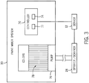
- FIG. 3 is a schematic diagram of an embodiment of the paint mixer system 30 that may be used as part of the intra-shop connectivity system 10 of FIG. 1 .
- the paint mixer system 30 may be connected to the server 12 via a controller 70 that has a processor 72 and memory 74.
- the processor 72 may receive instructions electronically from the server 12 and/or the scanner 60 (e.g., paint quantity, paint color, ratio of plural components of paint to mix to achieve paint color, time to mix paint, scheduled time to complete mix of paint, etc.) while the memory 74 may store instructions for mixing paint.
- paint when "paint" is used in describing the paint mixer, it may be understood that other liquids may also be used in the mixer such as hardeners, lacquers, stains, waxes, etc.
- the paint mixer system 30 also includes a pump 76 that pressurizes the paint for conveyance to the sprayer/scanner 28.
- the paint mixer system 30 may include a pump 76 that provides only air to the sprayer/scanner 28.
- the pump 76 may pump paint from one or more color reservoirs 78 that include different colored paint.
- the controller 70 uses the information in the memory 74 to control the amount and type of paint to mix from the color reservoirs 78, for example to match the color of the vehicle 18.
- the processor 72 may receive the correct colors and amounts to be fixed from the server 12.
- the color information that the controller 70 tries to match may come from a manufacturer's list, a picture taken by the scanner 60, a previously performed job for the vehicle 18, or a color manually selected by an operator.
- the paint mixer system 30 may begin mixing paint as soon as a signal is received from the server 12, which in turn may send a signal as soon as receiving a signal from the sprayer/scanner 28.
- a paint technician may scan the vehicle 18, begin paint preparations, while the paint mixer system 30 prepares the paint.
- the paint mixer may save material costs by accurately monitoring and measuring the paint that is used by the sprayer/scanner 28.
- the paint mixer system 30 may mix an amount of paint so that no paint is left over after the vehicle 18 is painted.
- the paint mixer system 30 may concurrently mix and pump the paint in real time so that only unmixed paint is left over after completion of the paint job.
- the server 12 may have information about how much paint should be used for a given component (e.g., a panel of the vehicle 18.) For example, the information may be based on past usage rates within the service shop, environmental conditions currently being detected using sensors 24 (e.g., thermometer, barometer, hygrometer, etc.) in the service shop, personal experience of the employees of the service shop, or other information.
- the paint mixer system 30 may mix a batch of paint based on similar criteria, the batch may be delivered to the sprayer/scanner 28 through a gravity feed container.
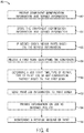
- FIG. 4 is a flow chart of a method 80 that may be used by the intra-shop connectivity intra-shop connectivity system 10 of FIG. 1 .
- the method 80 begins when the intra-shop connectivity system 10 receives 82 component identification information and service information.
- the identification information as disclosed above, may be entered into the intake terminal 20, on the internet 22, through sensors 24, or through the PEDs 26.
- the service information may include entries such as the repair to be done (e.g., paint panel, bumper, etc.), the desired time frame, color and amount, and/or employee assignment (e.g., who is assigned to do the service job).
- the intra-shop connectivity system 10 stores 84 the vehicle information and service information.
- the method 80 may be repeated for additional components, and/or may be repeated for the same component to store identification information at a second time (e.g., a second scan indicating an end time of the service job).
- the intra-shop connectivity system 10 may store the information on the server 12, so that any device (e.g., intake terminal 20, PED 26, etc.) in the intra-shop connectivity system 10 may access the vehicle and service information. For example, a manager may retrieve information to monitor a job to be done.
- the intra-shop connectivity system 10 and server 12 may receive and store information for any number of components, depending only on the amount of storage 16 (e.g., memory) within the server 12.
- the internet protocol 22 may also be utilized, if needed, to order 86 parts based on the service needs entered into the intra-shop connectivity system 10. For example, the server 12 may monitor the spare vehicle parts that are on hand in the service shop and order more parts automatically based on a programmed need.
- the intra-shop connectivity system 10 may be programmed to have a certain minimum number in the shop (e.g., 5, 10, 15, or more). If the number of parts is less than the minimum number, the intra-shop connectivity system 10 will order 92 over the internet. Additionally, the repair parts may be ordered 86 for specific repairs at the time that the information about the vehicle 18 and/or the repair is stored 84. Additionally, the internet protocol 22 may be used to deliver timing and location information to a secure website. This would enable a customer to look up or be notified when the vehicle 18 has started service or repairs, when parts have been ordered or have arrived, or when the service job has finished and the vehicle 18 is ready to be picked up. Specifically, the server 12 may also utilize the internet protocol 22 to send a first message indicating that the repair has started, and a second message indicating that the repair has ended.
- a certain minimum number in the shop e.g., 5, 10, 15, or more. If the number of parts is less than the minimum number, the intra-shop connectivity system 10 will order 92 over the internet. Additionally
- the intra-shop connectivity system 10 receives 88 a first scan identifying the vehicle 18.
- the intra-shop connectivity system 10 may receive 88 the scan at the sprayer/scanner 28.
- the scanner 60 receives the scan of the code, picture, or other identifying feature which may be used to determine 90 a job start time, a type of repair, a type of paint job, or any combination thereof based on the first scan.
- the intra-shop connectivity system 10 and/or the server 12 may then send 92 the paint job information to the paint mixer system 30 to prepare the paint for application to the vehicle 18, or dispense the mixed paint for use in a gravity feed container or suction feed container (disposable or reusable).
- the paint mixer system 30 may provide significant timing and material savings for the service shop.
- the information may be provided 94 to the internet 22 and other components of the intra-shop connectivity system 10 (e.g., intake terminal 20, PED 26, etc.).
- the information may be provided to the internet via a secured web portal such that each customer may securely view information regarding their vehicle 18 securely and privately.
- the intra-shop connectivity system 10 may also monitor 96 a residual amount of paint to determine whether an excess amount of paint was mixed.
- the monitoring over a long period of time and many paint jobs may enable the service shop to refine the amount that the intra-shop connectivity system 10 prepares (i.e., the amount that the server 12 instructs that paint mixer system 30 to mix).
- the residual amount of paint may be linked and correlated to environmental conditions, manufacturer recommendations, certain employees, and/or individual sprayer/scanners 28. That is, the residual amount of paint may change when the weather is humid/dry or windy, or the residual amount of paint may be consistently high for certain manufacturers and/or specific panels on certain vehicles 18. Also, certain employees may show signs of using too much or too little paint for the paints jobs that they do. Monitoring the residual amount of paint and correlating with the conditions may increase the accuracy with which the intra-shop connectivity system 10 mixes paint.
Landscapes
- Business, Economics & Management (AREA)
- Engineering & Computer Science (AREA)
- Economics (AREA)
- Accounting & Taxation (AREA)
- Finance (AREA)
- General Physics & Mathematics (AREA)
- Physics & Mathematics (AREA)
- Development Economics (AREA)
- Marketing (AREA)
- Strategic Management (AREA)
- General Business, Economics & Management (AREA)
- Theoretical Computer Science (AREA)
- Chemical & Material Sciences (AREA)
- General Engineering & Computer Science (AREA)
- Entrepreneurship & Innovation (AREA)
- Human Resources & Organizations (AREA)
- Operations Research (AREA)
- Quality & Reliability (AREA)
- Tourism & Hospitality (AREA)
- Chemical Kinetics & Catalysis (AREA)
- Analytical Chemistry (AREA)
- Automation & Control Theory (AREA)
- Management, Administration, Business Operations System, And Electronic Commerce (AREA)
- Application Of Or Painting With Fluid Materials (AREA)
- Spray Control Apparatus (AREA)
- Traffic Control Systems (AREA)
- Mobile Radio Communication Systems (AREA)
- Telephonic Communication Services (AREA)
Description
- The present disclosure relates generally to service shops and various tools and equipment used in service shops.
- Service shops, such as paint shops or service shops, may employ a number of processes and operators working simultaneously to accomplish jobs for customers. In many instances, the different processes being done by different operators may involve disjointed technologies in which there is little operator to operator communication through the shop as a whole. The lack of communication may result in bottlenecks that are unrecognized and cause inefficiencies throughout the service shop Examples of known systems are described in e.g.
WO 2011/163579 A1 ,WO 2011/163583 A1 andUS 2007/032965 . - Certain embodiments commensurate in scope with the originally claimed invention are summarized below. These embodiments are not intended to limit the scope of the claimed invention, but rather these embodiments are intended only to provide a brief summary of possible forms of the invention. Indeed, the invention may encompass a variety of forms that may be similar to or different from the embodiments set forth below.
- In a first aspect of the present invention, there is provided a system as set out in appended claim 1.
- In a second aspect of the present invention, there is provided a method as set out in appended claim 6.
- These and other features, aspects, and advantages of the present disclosure will become better understood when the following detailed description is read with reference to the accompanying drawings in which like characters represent like parts throughout the drawings.
-
FIG. 1 is a block diagram of an embodiment of an intra-shop connectivity system; -
FIG. 2 is a perspective view of an embodiment of a sprayer that may be used as part of the intra-shop connectivity system ofFIG. 1 ; -
FIG. 3 is a schematic diagram of an embodiment of a paint mixer system that may be used as part of the intra-shop connectivity system ofFIG. 1 ; and -
FIG. 4 is a flow chart of a method that may be used by the intra-shop connectivity system ofFIG. 1 . - One or more specific embodiments of the present disclosure will be described below. In an effort to provide a concise description of these embodiments, all features of an actual implementation may not be described in the specification. It should be appreciated that in the development of any such actual implementation, as in any engineering or design project, numerous implementation-specific decisions must be made to achieve the developers' specific goals, such as compliance with system-related and business-related constraints, which may vary from one implementation to another. Moreover, it should be appreciated that such a development effort might be complex and time consuming, but would nevertheless be a routine undertaking of design, fabrication, and manufacture for those of ordinary skill having the benefit of this disclosure.
- When introducing elements of various embodiments of the present disclosure, the articles "a," "an," "the," and "said" are intended to mean that there are one or more of the elements. The terms "comprising," "including," and "having" are intended to be inclusive and mean that there may be additional elements other than the listed elements. Any examples of operating parameters and/or environmental conditions are not exclusive of other parameters/conditions of the disclosed embodiments.
- As discussed in detail below, the disclosed embodiments include systems and methods used within a service shop (e.g., body shop, paint shop, etc.) to unify and streamline the service and repair of components by the shop. The service shop may thus include an intra-shop connectivity system that communicates with various systems (paint sprayer, paint mixer, central component intake kiosk, etc.) to obtain location, time, color, repair, and other information about the components. Thus, rather than relying on paper charts and notifications, a service shop may be able to centrally locate and monitor the service of each vehicle. Furthermore, bottlenecks in service and repair, usage amount of paint and finishes, and other information may be tracked to eliminate slow-down and enable smart decisions concerning purchases and customer service by the service shop. In the following discussion, the intra-shop connectivity system is introduced in context of a service shop for vehicle repair and service, yet the disclosed embodiments may be used in any service shop or facility with any suitable tools and equipment.
-
FIG. 1 is a block diagram of an embodiment of an intra-shop connectivityintra-shop connectivity system 10. Theintra-shop connectivity system 10 includes aserver 12 that connects and/or communicates with various components and subsystems of theintra-shop connectivity system 10. Theserver 12 may include aprocessor 14 andstorage 16 to store and distribute the information collected by the various components and subsystems of theintra-shop connectivity system 10. Theprocessor 14 may provide the processing capability to execute the operating system, programs, user and application interfaces, and any other functions of theserver 12. Theprocessor 14 may include one or more microprocessors, such as one or more "general-purpose" microprocessors, one or more special-purpose microprocessors or ASICS, or some combination of such processing components. For example, theprocessor 14 may include one or more reduced instruction set (RISC) processors, as well as graphics processors, video processors, audio processors, and the like. As will be appreciated, theprocessors 18 may be communicatively coupled to one or more data buses or chipsets for transferring data and instructions between various components of theserver 12. Thestorage 16 may include volatile or non-volatile memory configured to store information such as identification information (e.g., vehicle identification number, manufacturer's part number, model number, etc.), ordered job (e.g., job code or identification number), order date, order time, scheduled time of job completion, color of paint (e.g., paint code or identification number), replacement parts that have been ordered, owner's identification and contact information, assigned operator, or other information relating to avehicle 18. - The
vehicle 18 may be a customer'svehicle 18 that is, for example, submitted for service at the service shop. Identification information such as make, model, color, prior services, etc. may be collected and input into anintake terminal 20. Theintake terminal 20 may include a desktop computer located, for example, at a front entrance/checkout location where customers interact with employees of the service shop. In some embodiments, the intake terminal may be a personal electronic device (PED), such as a tablet computer, smartphone, laptop, etc. In addition to theintake terminal 20, theintra-shop connectivity system 10 may include aninternet protocol 22 configured to download and upload information (e.g., the identification information) from the internet (wired or wireless). For example, a customer may input the identification information via a web interface before bringing thevehicle 18 to the service shop. Additionally, information about suggested repairs, pricing estimates and results, expected time for completion of repairs, and other information about thevehicle 18 and the service provided by the service shop may be communicated to a customer through theinternet 22. - Local-area network devices may also be connected to the
server 12 from within the service shop. As an example, theintra-shop connectivity system 10 may includesensors 24 that detect useful information, such as a location of thevehicle 18, repair start and end times, environmental conditions (e.g., temperature, humidity, pressure, etc.), among others. The system may also include personal electronic devices (PEDs) 26 that wirelessly connect to theserver 12. Employees may use the PED 26 to interact with theserver 12 from anywhere within the service shop. For example, a paint technician may use thePED 26 to lookup information on theserver 12 to determine whichvehicle 18 is next in the queue for repairs. Since the PED 26 may receive this information from theserver 12 at any location within the service shop, the paint technician does not have to check a paper list that may be located far away or may be misplaced. The PED 26 ensures that each employee, manager, and/or customer has access to all information that has been entered into theserver 12. As explained in detail below, theintra-shop connectivity system 10 may also include a sprayer/scanner 28 configured to scan information and perform operations within the service shop. The sprayer/scanner 28 may include on-board circuitry components that store and process data for conveyance to theserver 12. For example, the sprayer/scanner may include aprocessor 36,memory 37,network circuitry 38, and a scanner 60 (explained in detail below). - In some embodiments, the
server 12 may also be configured to interact with components or subsystems of theintra-shop connectivity system 10 to automatically start processes within the service shop, improving efficiency. For example, theintra-shop connectivity system 10 may include apaint mixer system 30 that automatically mixes an amount of paint when thesensor 24, PED 26, etc detects a job is ready for painting. Thepaint mixer system 30, like the sprayer/scanner 28, may include on-board circuitry components that store and process data received from theserver 12. For example, thepaint mixer system 30 may include aprocessor 32, amemory 33, and/ornetwork circuitry 34. - The color and/or amount of paint to be either fed to the sprayer/
scanner 28 or dispensed for use with a gravity or suction feed sprayer/scanner 28 may be determined by input from an employee, or may be based on the identification information previously entered into the server 12 (e.g., through theintake terminal 20,internet 22,sensors 24,PED 26, or sprayer/scanner 28). Thus, each component of theintra-shop connectivity system 10 may cooperatively provide information rather than having all pieces of information stored in multiple physical and digital locations, or having some pieces of information in one location while other information is in a different location. -
FIG. 2 is a perspective view of an embodiment of the sprayer/scanner 28 that may be used as part of the intra-shop connectivityintra-shop connectivity system 10 ofFIG. 1 . The sprayer/scanner 28 may be directly connected to thepaint mixer system 30 via ahose 40 that may supply paint and/or air pressure to the sprayer/scanner 28. In certain embodiments, the sprayer/scanner 28 is an airless spray coating gun or an air-assisted spray coating gun (e.g., a spray gun that atomizes the liquid with air atomization mechanisms.) In certain other embodiments, the sprayer/scanner 28 may receive air through thehose 40 while receiving paint that has been mixed in thepaint mixer 30 but is dispensed for use with a gravity or suction feed spray-gun. For example, the gravity feed spray-gun container may be disposable or metal reusable containers. In such embodiments, thepaint mixer 30 may possibly mix the paint in a separate location and then the container may be attached to the sprayer/scanner 28. In operation, an air-assisted spray coating gun may also include air jets configured to shape the liquid spray in the desired pattern, e.g., flat, conical, hollow, and so forth. - Furthermore, the sprayer/
scanner 28 may include ahead assembly 42 coupled to abody assembly 44. The illustratedbody assembly 44 includes ahandle 46, anair supply coupling 48 disposed at thehandle 20, and aliquid supply coupling 49. Thebody assembly 44 also includes atrigger 50 rotatably coupled to a pivot joint 52. In turn, thetrigger 50 is movably coupled to an air valve assembly 54 and aliquid valve assembly 56, such that the trigger simultaneously controls the passage of air and liquid through the sprayer/scanner 28. In addition, thebody assembly 44 includes ascanner initiation assembly 58 in close proximity to thetrigger 50. Thescanner initiation assembly 58 enables a user to initiate a scanning operation by ascanner 60. Thescanner initiation assembly 58 may be located proximately to thetrigger 50 to enable quick activation of thescanner 60, while holding the sprayer/scanner 28. In operation, thescanner 60 may be activated to identify (e.g., scan) a code on thevehicle 18, vehicle replacement parts, paint containers or other service related goods. For example, thescanner 60 may scan anidentification label 62 with identification information printed on it and attached to thevehicle 18. For example, thelabel 62 may include a bar code, quick response (QR) code, a radio frequency identification code (RFID tag), an alphanumeric code, an alphanumeric information label, or other device with or containing a scanable indicia. Accordingly, thescanner 60 may include a bar code scanner, a QR code scanner, an RFID tag scanner, or any combination thereof. In some embodiments, thescanner 60 may identify a vehicle identification number (V.I.N.) of thevehicle 18 through a digital image of the V.I.N. location. In still further embodiments, thescanner 60 may include a camera that enables color detection of the component (e.g., vehicle 18). -
FIG. 3 is a schematic diagram of an embodiment of thepaint mixer system 30 that may be used as part of theintra-shop connectivity system 10 ofFIG. 1 . Thepaint mixer system 30 may be connected to theserver 12 via acontroller 70 that has aprocessor 72 andmemory 74. Theprocessor 72 may receive instructions electronically from theserver 12 and/or the scanner 60 (e.g., paint quantity, paint color, ratio of plural components of paint to mix to achieve paint color, time to mix paint, scheduled time to complete mix of paint, etc.) while thememory 74 may store instructions for mixing paint. As an aside, when "paint" is used in describing the paint mixer, it may be understood that other liquids may also be used in the mixer such as hardeners, lacquers, stains, waxes, etc. Thepaint mixer system 30 also includes apump 76 that pressurizes the paint for conveyance to the sprayer/scanner 28. In gravity feed embodiments of the sprayer/scanner 28, thepaint mixer system 30 may include apump 76 that provides only air to the sprayer/scanner 28. Thepump 76 may pump paint from one ormore color reservoirs 78 that include different colored paint. In operation, thecontroller 70 uses the information in thememory 74 to control the amount and type of paint to mix from thecolor reservoirs 78, for example to match the color of thevehicle 18. In some embodiments, theprocessor 72 may receive the correct colors and amounts to be fixed from theserver 12. The color information that thecontroller 70 tries to match may come from a manufacturer's list, a picture taken by thescanner 60, a previously performed job for thevehicle 18, or a color manually selected by an operator. Thepaint mixer system 30 may begin mixing paint as soon as a signal is received from theserver 12, which in turn may send a signal as soon as receiving a signal from the sprayer/scanner 28. Thus, in practice, a paint technician may scan thevehicle 18, begin paint preparations, while thepaint mixer system 30 prepares the paint. - Additionally, the paint mixer may save material costs by accurately monitoring and measuring the paint that is used by the sprayer/
scanner 28. For example, thepaint mixer system 30 may mix an amount of paint so that no paint is left over after thevehicle 18 is painted. In some embodiments, rather than mixing a batch of paint, with extra to ensure coverage, thepaint mixer system 30 may concurrently mix and pump the paint in real time so that only unmixed paint is left over after completion of the paint job. In some embodiments, theserver 12 may have information about how much paint should be used for a given component (e.g., a panel of thevehicle 18.) For example, the information may be based on past usage rates within the service shop, environmental conditions currently being detected using sensors 24 (e.g., thermometer, barometer, hygrometer, etc.) in the service shop, personal experience of the employees of the service shop, or other information. In additional embodiments, thepaint mixer system 30 may mix a batch of paint based on similar criteria, the batch may be delivered to the sprayer/scanner 28 through a gravity feed container. -
FIG. 4 is a flow chart of amethod 80 that may be used by the intra-shop connectivityintra-shop connectivity system 10 ofFIG. 1 . Themethod 80 begins when theintra-shop connectivity system 10 receives 82 component identification information and service information. The identification information, as disclosed above, may be entered into theintake terminal 20, on theinternet 22, throughsensors 24, or through thePEDs 26. The service information may include entries such as the repair to be done (e.g., paint panel, bumper, etc.), the desired time frame, color and amount, and/or employee assignment (e.g., who is assigned to do the service job). After the information is received 82, theintra-shop connectivity system 10stores 84 the vehicle information and service information. Themethod 80 may be repeated for additional components, and/or may be repeated for the same component to store identification information at a second time (e.g., a second scan indicating an end time of the service job). - The
intra-shop connectivity system 10 may store the information on theserver 12, so that any device (e.g.,intake terminal 20,PED 26, etc.) in theintra-shop connectivity system 10 may access the vehicle and service information. For example, a manager may retrieve information to monitor a job to be done. Theintra-shop connectivity system 10 andserver 12 may receive and store information for any number of components, depending only on the amount of storage 16 (e.g., memory) within theserver 12. Theinternet protocol 22 may also be utilized, if needed, to order 86 parts based on the service needs entered into theintra-shop connectivity system 10. For example, theserver 12 may monitor the spare vehicle parts that are on hand in the service shop and order more parts automatically based on a programmed need. That is, for a given type of part (e.g., car battery), theintra-shop connectivity system 10 may be programmed to have a certain minimum number in the shop (e.g., 5, 10, 15, or more). If the number of parts is less than the minimum number, theintra-shop connectivity system 10 will order 92 over the internet. Additionally, the repair parts may be ordered 86 for specific repairs at the time that the information about thevehicle 18 and/or the repair is stored 84. Additionally, theinternet protocol 22 may be used to deliver timing and location information to a secure website. This would enable a customer to look up or be notified when thevehicle 18 has started service or repairs, when parts have been ordered or have arrived, or when the service job has finished and thevehicle 18 is ready to be picked up. Specifically, theserver 12 may also utilize theinternet protocol 22 to send a first message indicating that the repair has started, and a second message indicating that the repair has ended. - After storing, the
intra-shop connectivity system 10 receives 88 a first scan identifying thevehicle 18. For example, theintra-shop connectivity system 10 may receive 88 the scan at the sprayer/scanner 28. Thescanner 60 receives the scan of the code, picture, or other identifying feature which may be used to determine 90 a job start time, a type of repair, a type of paint job, or any combination thereof based on the first scan. Theintra-shop connectivity system 10 and/or theserver 12 may then send 92 the paint job information to thepaint mixer system 30 to prepare the paint for application to thevehicle 18, or dispense the mixed paint for use in a gravity feed container or suction feed container (disposable or reusable). As described above, thepaint mixer system 30 may provide significant timing and material savings for the service shop. Once the information has been stored 84 or received 88 by theintra-shop connectivity system 10, the information may be provided 94 to theinternet 22 and other components of the intra-shop connectivity system 10 (e.g.,intake terminal 20,PED 26, etc.). The information may be provided to the internet via a secured web portal such that each customer may securely view information regarding theirvehicle 18 securely and privately. - The
intra-shop connectivity system 10 may also monitor 96 a residual amount of paint to determine whether an excess amount of paint was mixed. The monitoring over a long period of time and many paint jobs may enable the service shop to refine the amount that theintra-shop connectivity system 10 prepares (i.e., the amount that theserver 12 instructs thatpaint mixer system 30 to mix). The residual amount of paint may be linked and correlated to environmental conditions, manufacturer recommendations, certain employees, and/or individual sprayer/scanners 28. That is, the residual amount of paint may change when the weather is humid/dry or windy, or the residual amount of paint may be consistently high for certain manufacturers and/or specific panels oncertain vehicles 18. Also, certain employees may show signs of using too much or too little paint for the paints jobs that they do. Monitoring the residual amount of paint and correlating with the conditions may increase the accuracy with which theintra-shop connectivity system 10 mixes paint. - The systems and methods disclosed herein provide benefits in time and material savings in service shops. Uniform information throughout the service shop provides employees with an accurate idea of what they are expected to work on next and gives them the material and tools they need to quickly finish one job and begin the next. While the invention may be susceptible to various modifications and alternative forms, specific embodiments have been shown by way of example in the drawings and have been described in detail herein. However, it should be understood that the invention is not intended to be limited to the particular forms disclosed. Rather, the invention is to cover all modifications, equivalents, and alternatives falling within the scope of the invention as defined by the following appended claims.
Claims (14)
- A system, comprising:
an intra-shop connectivity system (10) configured to be positioned within a service shop, comprising:a terminal (20) configured to intake a vehicle into the service shop by receiving vehicle identification information associated with the vehicle;a server (12) comprising a processor and a volatile or non-volatile memory, the server configured to store vehicle data associated with the vehicle, wherein the vehicle data comprises the vehicle identification information, ordered job information, color of paint for the vehicle, assigned operator, job start time, and job end time; anda scanner (60) of a spray gun of a coating system, wherein the scanner is configured to scan a scannable indicia of the vehicle to identify the vehicle and relay the vehicle identification information to the server;wherein the intra-shop connectivity system is configured to control an amount and color of paint supplied to the spray gun in the service shop based at least in part on the vehicle identification information. - The system of claim 1, comprising the coating system, wherein the coating system comprises a paint mixer (30) configured to trigger mixing of paint in response to identification of the vehicle by the scanner.
- The system of claim 2, wherein the amount and color of paint are determined by the server.
- The system of claim 1, wherein the intra-shop connectivity system comprises sensors (24) to determine environmental conditions within the service shop and convey the environmental conditions to the server, and the amount of paint is determined based in part on the environmental conditions.
- The system of claim 1, wherein the server comprises an internet communication protocol configured to deliver the vehicle data to a secure website.
- A method (80), comprising:receiving (82), with a processor (32) located within a service shop, identification information and service information relating to a coating process for a vehicle within the service shop;storing (84) the identification information and the service information on a server (12) within the service shop accessible from a plurality of locations within the service shop;receiving (88), from a first scanner (60) of a spray gun of a coating system within the service shop, a first scan of a scannable indicia of the vehicle, the first scan enabling the processor to determine a start time of a repair, a type of repair, a type of paint job, or any combination thereof, and providing an identification of the vehicle; anddetermining (90), with the processor and based on the identification information, an amount of paint to be supplied to the spray gun within the service shop and a color of paint to be supplied to the spray gun within the service shop.
- The method of claim 6, comprising automatically ordering (86) repair parts based on the service information.
- The method of claim 6, further comprising sending (92) a signal to a paint mixer (30), wherein the signal comprises information relating to the color of paint and the amount of paint.
- The method of claim 8, wherein the information is automatically determined, with the processor, based on the identification information and the service information.
- The method of claim 8, comprising receiving, from sensors (24), signals indicative of environmental conditions, wherein the information is based at least in part on the environmental conditions.
- The method of claim 8, wherein the information is based at least in part on previous amounts and corresponding excess amounts of paint.
- The method of claim 8, comprising providing (94) the start time of the repair, the coating process, or any combination thereof, and the identification of the vehicle to an internet website.
- The method of claim 6, comprising receiving (82), from the first scanner or a second scanner (28), a second scan identifying the vehicle, wherein the second scan indicates an end time of the repair.
- The method of claim 6, comprising monitoring (96) a residual amount of paint leftover after the coating process ends.
Applications Claiming Priority (3)
| Application Number | Priority Date | Filing Date | Title |
|---|---|---|---|
| US201562115529P | 2015-02-12 | 2015-02-12 | |
| US15/040,911 US10324428B2 (en) | 2015-02-12 | 2016-02-10 | Intra-shop connectivity system |
| PCT/US2016/017624 WO2016130852A1 (en) | 2015-02-12 | 2016-02-11 | Intra-shop connectivity system and method |
Publications (2)
| Publication Number | Publication Date |
|---|---|
| EP3256352A1 EP3256352A1 (en) | 2017-12-20 |
| EP3256352B1 true EP3256352B1 (en) | 2021-05-12 |
Family
ID=55521800
Family Applications (1)
| Application Number | Title | Priority Date | Filing Date |
|---|---|---|---|
| EP16709179.2A Active EP3256352B1 (en) | 2015-02-12 | 2016-02-11 | Intra-shop connectivity system and method |
Country Status (9)
| Country | Link |
|---|---|
| US (1) | US10324428B2 (en) |
| EP (1) | EP3256352B1 (en) |
| JP (1) | JP6659709B2 (en) |
| CN (1) | CN107635673B (en) |
| AU (1) | AU2016219217B2 (en) |
| BR (1) | BR112017015927A2 (en) |
| CA (1) | CA2974834A1 (en) |
| MX (1) | MX2017010268A (en) |
| WO (1) | WO2016130852A1 (en) |
Families Citing this family (3)
| Publication number | Priority date | Publication date | Assignee | Title |
|---|---|---|---|---|
| CN109622334A (en) * | 2018-12-18 | 2019-04-16 | 浙江鼎澈科技股份有限公司 | A kind of intelligent Web vehicle paint quickly repairs assembly line |
| EP4051438B1 (en) * | 2019-10-31 | 2024-10-23 | Carlisle Fluid Technologies, LLC | Systems and methods for improved fluid gun delivery systems |
| EP4168959A1 (en) | 2020-06-18 | 2023-04-26 | PPG Industries Ohio Inc. | Coating composition scale network device |
Family Cites Families (46)
| Publication number | Priority date | Publication date | Assignee | Title |
|---|---|---|---|---|
| US4722625A (en) | 1985-09-26 | 1988-02-02 | Triune Automated Painting Systems | Remote control device for powered painting system |
| SE458749B (en) | 1988-05-18 | 1989-05-08 | Bengtsson Bengt Goeran | PROCEDURE AND DEVICE FOR REGULATION OF SPRAYING OF COATING MATERIAL |
| US5099687A (en) | 1990-12-21 | 1992-03-31 | Graco Inc. | Electrically neutral flow measurement system |
| US5636653A (en) | 1995-12-01 | 1997-06-10 | Perception Incorporated | Fluid metering apparatus and method |
| DE19738141C2 (en) | 1997-09-01 | 2003-06-05 | Wagner Int | Control system of a coating system with a LON bus structure |
| US6073055A (en) * | 1997-11-10 | 2000-06-06 | Basf Corporation | Computerized virtual paint manufacturing and application system |
| US6149071A (en) | 1998-06-10 | 2000-11-21 | Global Metering Solutions, Llc | Flow control system for spray applications |
| JP2000085864A (en) | 1998-09-09 | 2000-03-28 | Osaka Ship Building Co Ltd | Delivery system |
| US6996509B2 (en) * | 1998-10-19 | 2006-02-07 | Ford Global Technologies, Llc | Paint spray particle trajectory analysis method and system |
| DE19848640C2 (en) | 1998-10-22 | 2000-10-19 | Graco Verfahrenstechnik Gmbh | Method and device for dosing and mixing different components |
| WO2001064325A1 (en) | 2000-03-02 | 2001-09-07 | Graco Minnesota Inc. | Electronic plural component proportioner |
| US7743055B2 (en) | 2000-03-28 | 2010-06-22 | E.I. Du Pont De Nemours And Company | Digital display of color and appearance and the use thereof |
| FR2809334B1 (en) | 2000-05-29 | 2003-02-28 | Eisenmann Sarl | SPRAYING DEVICE FOR SPRAYING A COATING PRODUCT |
| US20020007237A1 (en) * | 2000-06-14 | 2002-01-17 | Phung Tam A. | Method and system for the diagnosis of vehicles |
| US7363100B2 (en) | 2000-08-03 | 2008-04-22 | Nordson Corporation | Material application system with remote access |
| US6628829B1 (en) | 2000-08-08 | 2003-09-30 | Richard Jeffrey Chasen | Method and system for matching a surface color |
| US6500262B1 (en) | 2000-10-31 | 2002-12-31 | Nordson Corporation | Remote control device for painting system |
| US6564154B1 (en) * | 2000-11-28 | 2003-05-13 | Steelcase Development Corporation | Monitoring system |
| US7024285B2 (en) | 2001-05-09 | 2006-04-04 | Spraying Systems Co. | Object-oriented operating system for a spray controller |
| JP4348895B2 (en) * | 2002-03-29 | 2009-10-21 | トヨタ自動車株式会社 | System and management method for managing paint quality of automobile body group |
| US7017834B2 (en) * | 2002-08-15 | 2006-03-28 | Santa Cruz Cathy D | Liquid storage, dispensing, mixing, application, system and method of use |
| US20040087153A1 (en) | 2002-10-31 | 2004-05-06 | Yan Du | Method of etching a silicon-containing dielectric material |
| JP4619019B2 (en) | 2003-04-21 | 2011-01-26 | 関西ペイント株式会社 | Paint supply method and apparatus |
| JP2007502703A (en) | 2003-08-18 | 2007-02-15 | ノードソン コーポレーション | Wireless operator interface for material application system |
| ATE535312T1 (en) * | 2003-08-21 | 2011-12-15 | Bae Systems Plc | IMPROVEMENTS IN OR RELATING TO SPRAY COATING |
| US7264160B2 (en) | 2004-01-14 | 2007-09-04 | E.I. Du Pont De Nemours And Company | Process for monitoring production of compositions |
| US7822845B2 (en) | 2004-01-14 | 2010-10-26 | E. I. Du Pont De Nemours & Co. | Monitoring device used for producing compositions |
| DE102005010835A1 (en) | 2005-03-07 | 2006-09-14 | Itw Gema Ag | Spray coating control unit |
| US20070032965A1 (en) | 2005-07-20 | 2007-02-08 | Basf Corporation | System and method for determining a paint formula with a portable device |
| US20070145113A1 (en) * | 2005-11-30 | 2007-06-28 | Wiredtime.Com, Inc. | Barcode based time and location tracking method and system |
| DE102006056879A1 (en) | 2006-12-01 | 2008-06-05 | Dürr Systems GmbH | Error logging procedure for a coating plant |
| US7792661B1 (en) | 2007-02-14 | 2010-09-07 | Symantec Corporation | Realtime feature adaptation responsive to dynamically gathered usability information |
| WO2008121358A1 (en) | 2007-03-29 | 2008-10-09 | E. I. Du Pont De Nemours And Company | System for color match and digital color display |
| US20120109660A1 (en) | 2007-10-23 | 2012-05-03 | Gann Xu | Integrated process and system for cosmetic vehicle repairs |
| JP5029286B2 (en) | 2007-10-25 | 2012-09-19 | マツダ株式会社 | Cartridge type painting system |
| US8037844B2 (en) | 2007-10-31 | 2011-10-18 | Nordson Corporation | Spray gun having display and control members on gun |
| JP2009154087A (en) | 2007-12-26 | 2009-07-16 | Toshiba Elevator Co Ltd | Coating system for elevator panel article, and processing-coating system for elevator panel article |
| US8109685B1 (en) | 2008-08-26 | 2012-02-07 | John Vito | Liquid dispenser with interchangeable head and remote operating mechanism |
| US20100319176A1 (en) | 2009-06-23 | 2010-12-23 | E. I. Du Pont De Nemours And Company | Smart system for vehicle cosmetic repair |
| US8561921B1 (en) | 2009-10-16 | 2013-10-22 | Steve C. Showman | Plural component mixing system |
| IT1398982B1 (en) | 2010-03-17 | 2013-03-28 | Etatron D S Spa | PISTON STROKE CONTROL DEVICE FOR A DOSING PUMP FOR AUTOMATIC ADJUSTMENT OF THE HIGH PERFORMANCE FLOW RATE. |
| EP2585959A4 (en) | 2010-06-25 | 2015-07-29 | Coatings Foreign Ip Co Llc | System for producing and delivering matching color coating and use thereof |
| WO2011163579A1 (en) | 2010-06-25 | 2011-12-29 | E. I. Du Pont De Nemours And Company | Process for producing and delivering matching color coating and use thereof |
| WO2012037267A1 (en) | 2010-09-17 | 2012-03-22 | Steven Nielsen | Methods and apparatus for dispensing material and electronically tracking same |
| US8782026B2 (en) * | 2011-03-31 | 2014-07-15 | Honda Motor Co., Ltd. | Color harmony with process and environmental feedback |
| EP2641661B1 (en) | 2012-03-20 | 2016-05-11 | Hexagon Technology Center GmbH | Graphical application system |
-
2016
- 2016-02-10 US US15/040,911 patent/US10324428B2/en not_active Expired - Fee Related
- 2016-02-11 AU AU2016219217A patent/AU2016219217B2/en not_active Ceased
- 2016-02-11 BR BR112017015927-9A patent/BR112017015927A2/en not_active IP Right Cessation
- 2016-02-11 WO PCT/US2016/017624 patent/WO2016130852A1/en not_active Ceased
- 2016-02-11 EP EP16709179.2A patent/EP3256352B1/en active Active
- 2016-02-11 CA CA2974834A patent/CA2974834A1/en not_active Abandoned
- 2016-02-11 MX MX2017010268A patent/MX2017010268A/en unknown
- 2016-02-11 JP JP2017542134A patent/JP6659709B2/en active Active
- 2016-02-11 CN CN201680009785.6A patent/CN107635673B/en not_active Expired - Fee Related
Non-Patent Citations (1)
| Title |
|---|
| None * |
Also Published As
| Publication number | Publication date |
|---|---|
| CN107635673B (en) | 2020-01-10 |
| JP2018507774A (en) | 2018-03-22 |
| CN107635673A (en) | 2018-01-26 |
| US10324428B2 (en) | 2019-06-18 |
| MX2017010268A (en) | 2017-11-28 |
| WO2016130852A1 (en) | 2016-08-18 |
| AU2016219217B2 (en) | 2019-02-21 |
| AU2016219217A1 (en) | 2017-08-10 |
| BR112017015927A2 (en) | 2018-03-27 |
| CA2974834A1 (en) | 2016-08-18 |
| US20160239003A1 (en) | 2016-08-18 |
| JP6659709B2 (en) | 2020-03-04 |
| EP3256352A1 (en) | 2017-12-20 |
Similar Documents
| Publication | Publication Date | Title |
|---|---|---|
| EP2872262B2 (en) | System and method for automated production, application and evaluation of coating compositions | |
| US10324428B2 (en) | Intra-shop connectivity system | |
| KR102897857B1 (en) | Dye dispensing system | |
| US20160228901A1 (en) | Spray tool system | |
| US12521740B2 (en) | Portable low-pressure airless sprayer | |
| JP2018077651A (en) | Recycled paint production support device, regenerated paint production support method and program | |
| US20070079755A1 (en) | Material application system having component with wireless identification capabilities | |
| JP2025124712A (en) | Production management system, production management program | |
| US20190202197A1 (en) | Processing machine system and method for operating a processing machine system | |
| WO2023233306A1 (en) | Method and system for applying coatings | |
| EP2655084B1 (en) | Paint chip dispenser | |
| JP7245665B2 (en) | Lubricant sales system | |
| US20090112347A1 (en) | Article Marking System | |
| US20240416378A1 (en) | A spray booth | |
| AU2006308778B2 (en) | Article marking system | |
| Pawtucket | Custom Aerosol Packaging Piqua, Ohio | |
| DE102015002086A1 (en) | Devices with a device for triggering an order process and method for triggering an order process | |
| DE202015001287U1 (en) | Devices with a device for triggering an ordering process | |
| CN108021116A (en) | A kind of intelligence transfer device |
Legal Events
| Date | Code | Title | Description |
|---|---|---|---|
| STAA | Information on the status of an ep patent application or granted ep patent |
Free format text: STATUS: THE INTERNATIONAL PUBLICATION HAS BEEN MADE |
|
| PUAI | Public reference made under article 153(3) epc to a published international application that has entered the european phase |
Free format text: ORIGINAL CODE: 0009012 |
|
| STAA | Information on the status of an ep patent application or granted ep patent |
Free format text: STATUS: REQUEST FOR EXAMINATION WAS MADE |
|
| 17P | Request for examination filed |
Effective date: 20170725 |
|
| AK | Designated contracting states |
Kind code of ref document: A1 Designated state(s): AL AT BE BG CH CY CZ DE DK EE ES FI FR GB GR HR HU IE IS IT LI LT LU LV MC MK MT NL NO PL PT RO RS SE SI SK SM TR |
|
| AX | Request for extension of the european patent |
Extension state: BA ME |
|
| DAV | Request for validation of the european patent (deleted) | ||
| DAX | Request for extension of the european patent (deleted) | ||
| STAA | Information on the status of an ep patent application or granted ep patent |
Free format text: STATUS: EXAMINATION IS IN PROGRESS |
|
| 17Q | First examination report despatched |
Effective date: 20190301 |
|
| GRAP | Despatch of communication of intention to grant a patent |
Free format text: ORIGINAL CODE: EPIDOSNIGR1 |
|
| STAA | Information on the status of an ep patent application or granted ep patent |
Free format text: STATUS: GRANT OF PATENT IS INTENDED |
|
| RIC1 | Information provided on ipc code assigned before grant |
Ipc: B05B 12/12 20060101ALI20201125BHEP Ipc: B01F 13/10 20060101ALI20201125BHEP Ipc: B05B 7/02 20060101ALI20201125BHEP Ipc: B60S 5/00 20060101AFI20201125BHEP Ipc: G06Q 10/08 20120101ALI20201125BHEP Ipc: G06Q 30/06 20120101ALI20201125BHEP Ipc: G06Q 10/00 20120101ALI20201125BHEP Ipc: B05B 12/14 20060101ALI20201125BHEP Ipc: B05B 9/01 20060101ALI20201125BHEP |
|
| INTG | Intention to grant announced |
Effective date: 20201209 |
|
| GRAS | Grant fee paid |
Free format text: ORIGINAL CODE: EPIDOSNIGR3 |
|
| GRAA | (expected) grant |
Free format text: ORIGINAL CODE: 0009210 |
|
| STAA | Information on the status of an ep patent application or granted ep patent |
Free format text: STATUS: THE PATENT HAS BEEN GRANTED |
|
| AK | Designated contracting states |
Kind code of ref document: B1 Designated state(s): AL AT BE BG CH CY CZ DE DK EE ES FI FR GB GR HR HU IE IS IT LI LT LU LV MC MK MT NL NO PL PT RO RS SE SI SK SM TR |
|
| REG | Reference to a national code |
Ref country code: GB Ref legal event code: FG4D |
|
| REG | Reference to a national code |
Ref country code: CH Ref legal event code: EP |
|
| REG | Reference to a national code |
Ref country code: DE Ref legal event code: R096 Ref document number: 602016057726 Country of ref document: DE |
|
| REG | Reference to a national code |
Ref country code: IE Ref legal event code: FG4D |
|
| REG | Reference to a national code |
Ref country code: AT Ref legal event code: REF Ref document number: 1391998 Country of ref document: AT Kind code of ref document: T Effective date: 20210615 |
|
| REG | Reference to a national code |
Ref country code: LT Ref legal event code: MG9D |
|
| REG | Reference to a national code |
Ref country code: AT Ref legal event code: MK05 Ref document number: 1391998 Country of ref document: AT Kind code of ref document: T Effective date: 20210512 |
|
| REG | Reference to a national code |
Ref country code: NL Ref legal event code: MP Effective date: 20210512 |
|
| PG25 | Lapsed in a contracting state [announced via postgrant information from national office to epo] |
Ref country code: HR Free format text: LAPSE BECAUSE OF FAILURE TO SUBMIT A TRANSLATION OF THE DESCRIPTION OR TO PAY THE FEE WITHIN THE PRESCRIBED TIME-LIMIT Effective date: 20210512 Ref country code: AT Free format text: LAPSE BECAUSE OF FAILURE TO SUBMIT A TRANSLATION OF THE DESCRIPTION OR TO PAY THE FEE WITHIN THE PRESCRIBED TIME-LIMIT Effective date: 20210512 Ref country code: BG Free format text: LAPSE BECAUSE OF FAILURE TO SUBMIT A TRANSLATION OF THE DESCRIPTION OR TO PAY THE FEE WITHIN THE PRESCRIBED TIME-LIMIT Effective date: 20210812 Ref country code: FI Free format text: LAPSE BECAUSE OF FAILURE TO SUBMIT A TRANSLATION OF THE DESCRIPTION OR TO PAY THE FEE WITHIN THE PRESCRIBED TIME-LIMIT Effective date: 20210512 Ref country code: LT Free format text: LAPSE BECAUSE OF FAILURE TO SUBMIT A TRANSLATION OF THE DESCRIPTION OR TO PAY THE FEE WITHIN THE PRESCRIBED TIME-LIMIT Effective date: 20210512 |
|
| PG25 | Lapsed in a contracting state [announced via postgrant information from national office to epo] |
Ref country code: LV Free format text: LAPSE BECAUSE OF FAILURE TO SUBMIT A TRANSLATION OF THE DESCRIPTION OR TO PAY THE FEE WITHIN THE PRESCRIBED TIME-LIMIT Effective date: 20210512 Ref country code: GR Free format text: LAPSE BECAUSE OF FAILURE TO SUBMIT A TRANSLATION OF THE DESCRIPTION OR TO PAY THE FEE WITHIN THE PRESCRIBED TIME-LIMIT Effective date: 20210813 Ref country code: IS Free format text: LAPSE BECAUSE OF FAILURE TO SUBMIT A TRANSLATION OF THE DESCRIPTION OR TO PAY THE FEE WITHIN THE PRESCRIBED TIME-LIMIT Effective date: 20210912 Ref country code: PT Free format text: LAPSE BECAUSE OF FAILURE TO SUBMIT A TRANSLATION OF THE DESCRIPTION OR TO PAY THE FEE WITHIN THE PRESCRIBED TIME-LIMIT Effective date: 20210913 Ref country code: NO Free format text: LAPSE BECAUSE OF FAILURE TO SUBMIT A TRANSLATION OF THE DESCRIPTION OR TO PAY THE FEE WITHIN THE PRESCRIBED TIME-LIMIT Effective date: 20210812 Ref country code: PL Free format text: LAPSE BECAUSE OF FAILURE TO SUBMIT A TRANSLATION OF THE DESCRIPTION OR TO PAY THE FEE WITHIN THE PRESCRIBED TIME-LIMIT Effective date: 20210512 Ref country code: SE Free format text: LAPSE BECAUSE OF FAILURE TO SUBMIT A TRANSLATION OF THE DESCRIPTION OR TO PAY THE FEE WITHIN THE PRESCRIBED TIME-LIMIT Effective date: 20210512 Ref country code: RS Free format text: LAPSE BECAUSE OF FAILURE TO SUBMIT A TRANSLATION OF THE DESCRIPTION OR TO PAY THE FEE WITHIN THE PRESCRIBED TIME-LIMIT Effective date: 20210512 |
|
| PG25 | Lapsed in a contracting state [announced via postgrant information from national office to epo] |
Ref country code: NL Free format text: LAPSE BECAUSE OF FAILURE TO SUBMIT A TRANSLATION OF THE DESCRIPTION OR TO PAY THE FEE WITHIN THE PRESCRIBED TIME-LIMIT Effective date: 20210512 |
|
| PG25 | Lapsed in a contracting state [announced via postgrant information from national office to epo] |
Ref country code: SM Free format text: LAPSE BECAUSE OF FAILURE TO SUBMIT A TRANSLATION OF THE DESCRIPTION OR TO PAY THE FEE WITHIN THE PRESCRIBED TIME-LIMIT Effective date: 20210512 Ref country code: SK Free format text: LAPSE BECAUSE OF FAILURE TO SUBMIT A TRANSLATION OF THE DESCRIPTION OR TO PAY THE FEE WITHIN THE PRESCRIBED TIME-LIMIT Effective date: 20210512 Ref country code: DK Free format text: LAPSE BECAUSE OF FAILURE TO SUBMIT A TRANSLATION OF THE DESCRIPTION OR TO PAY THE FEE WITHIN THE PRESCRIBED TIME-LIMIT Effective date: 20210512 Ref country code: CZ Free format text: LAPSE BECAUSE OF FAILURE TO SUBMIT A TRANSLATION OF THE DESCRIPTION OR TO PAY THE FEE WITHIN THE PRESCRIBED TIME-LIMIT Effective date: 20210512 Ref country code: EE Free format text: LAPSE BECAUSE OF FAILURE TO SUBMIT A TRANSLATION OF THE DESCRIPTION OR TO PAY THE FEE WITHIN THE PRESCRIBED TIME-LIMIT Effective date: 20210512 Ref country code: RO Free format text: LAPSE BECAUSE OF FAILURE TO SUBMIT A TRANSLATION OF THE DESCRIPTION OR TO PAY THE FEE WITHIN THE PRESCRIBED TIME-LIMIT Effective date: 20210512 Ref country code: ES Free format text: LAPSE BECAUSE OF FAILURE TO SUBMIT A TRANSLATION OF THE DESCRIPTION OR TO PAY THE FEE WITHIN THE PRESCRIBED TIME-LIMIT Effective date: 20210512 |
|
| REG | Reference to a national code |
Ref country code: DE Ref legal event code: R097 Ref document number: 602016057726 Country of ref document: DE |
|
| PLBE | No opposition filed within time limit |
Free format text: ORIGINAL CODE: 0009261 |
|
| STAA | Information on the status of an ep patent application or granted ep patent |
Free format text: STATUS: NO OPPOSITION FILED WITHIN TIME LIMIT |
|
| 26N | No opposition filed |
Effective date: 20220215 |
|
| PG25 | Lapsed in a contracting state [announced via postgrant information from national office to epo] |
Ref country code: IS Free format text: LAPSE BECAUSE OF FAILURE TO SUBMIT A TRANSLATION OF THE DESCRIPTION OR TO PAY THE FEE WITHIN THE PRESCRIBED TIME-LIMIT Effective date: 20210912 Ref country code: AL Free format text: LAPSE BECAUSE OF FAILURE TO SUBMIT A TRANSLATION OF THE DESCRIPTION OR TO PAY THE FEE WITHIN THE PRESCRIBED TIME-LIMIT Effective date: 20210512 |
|
| PG25 | Lapsed in a contracting state [announced via postgrant information from national office to epo] |
Ref country code: IT Free format text: LAPSE BECAUSE OF FAILURE TO SUBMIT A TRANSLATION OF THE DESCRIPTION OR TO PAY THE FEE WITHIN THE PRESCRIBED TIME-LIMIT Effective date: 20210512 |
|
| PG25 | Lapsed in a contracting state [announced via postgrant information from national office to epo] |
Ref country code: MC Free format text: LAPSE BECAUSE OF FAILURE TO SUBMIT A TRANSLATION OF THE DESCRIPTION OR TO PAY THE FEE WITHIN THE PRESCRIBED TIME-LIMIT Effective date: 20210512 |
|
| REG | Reference to a national code |
Ref country code: CH Ref legal event code: PL |
|
| REG | Reference to a national code |
Ref country code: BE Ref legal event code: MM Effective date: 20220228 |
|
| PG25 | Lapsed in a contracting state [announced via postgrant information from national office to epo] |
Ref country code: LU Free format text: LAPSE BECAUSE OF NON-PAYMENT OF DUE FEES Effective date: 20220211 |
|
| PG25 | Lapsed in a contracting state [announced via postgrant information from national office to epo] |
Ref country code: FR Free format text: LAPSE BECAUSE OF NON-PAYMENT OF DUE FEES Effective date: 20220228 |
|
| PG25 | Lapsed in a contracting state [announced via postgrant information from national office to epo] |
Ref country code: LI Free format text: LAPSE BECAUSE OF NON-PAYMENT OF DUE FEES Effective date: 20220228 Ref country code: IE Free format text: LAPSE BECAUSE OF NON-PAYMENT OF DUE FEES Effective date: 20220211 Ref country code: CH Free format text: LAPSE BECAUSE OF NON-PAYMENT OF DUE FEES Effective date: 20220228 |
|
| PG25 | Lapsed in a contracting state [announced via postgrant information from national office to epo] |
Ref country code: BE Free format text: LAPSE BECAUSE OF NON-PAYMENT OF DUE FEES Effective date: 20220228 |
|
| REG | Reference to a national code |
Ref country code: DE Ref legal event code: R081 Ref document number: 602016057726 Country of ref document: DE Owner name: CARLISLE FLUID TECHNOLOGIES, LLC (N.D.GES. D. , US Free format text: FORMER OWNER: CARLISLE FLUID TECHNOLOGIES, INC., CHARLOTTE, NC, US |
|
| PG25 | Lapsed in a contracting state [announced via postgrant information from national office to epo] |
Ref country code: HU Free format text: LAPSE BECAUSE OF FAILURE TO SUBMIT A TRANSLATION OF THE DESCRIPTION OR TO PAY THE FEE WITHIN THE PRESCRIBED TIME-LIMIT; INVALID AB INITIO Effective date: 20160211 |
|
| REG | Reference to a national code |
Ref country code: GB Ref legal event code: 732E Free format text: REGISTERED BETWEEN 20240314 AND 20240320 |
|
| PG25 | Lapsed in a contracting state [announced via postgrant information from national office to epo] |
Ref country code: MK Free format text: LAPSE BECAUSE OF FAILURE TO SUBMIT A TRANSLATION OF THE DESCRIPTION OR TO PAY THE FEE WITHIN THE PRESCRIBED TIME-LIMIT Effective date: 20210512 Ref country code: CY Free format text: LAPSE BECAUSE OF FAILURE TO SUBMIT A TRANSLATION OF THE DESCRIPTION OR TO PAY THE FEE WITHIN THE PRESCRIBED TIME-LIMIT Effective date: 20210512 |
|
| PG25 | Lapsed in a contracting state [announced via postgrant information from national office to epo] |
Ref country code: TR Free format text: LAPSE BECAUSE OF FAILURE TO SUBMIT A TRANSLATION OF THE DESCRIPTION OR TO PAY THE FEE WITHIN THE PRESCRIBED TIME-LIMIT Effective date: 20210512 |
|
| PG25 | Lapsed in a contracting state [announced via postgrant information from national office to epo] |
Ref country code: MT Free format text: LAPSE BECAUSE OF FAILURE TO SUBMIT A TRANSLATION OF THE DESCRIPTION OR TO PAY THE FEE WITHIN THE PRESCRIBED TIME-LIMIT Effective date: 20210512 |
|
| PGFP | Annual fee paid to national office [announced via postgrant information from national office to epo] |
Ref country code: GB Payment date: 20260219 Year of fee payment: 11 |
|
| PGFP | Annual fee paid to national office [announced via postgrant information from national office to epo] |
Ref country code: DE Payment date: 20260218 Year of fee payment: 11 |