EP3256284B1 - Method for overlap laser welding - Google Patents
Method for overlap laser welding Download PDFInfo
- Publication number
- EP3256284B1 EP3256284B1 EP16708193.4A EP16708193A EP3256284B1 EP 3256284 B1 EP3256284 B1 EP 3256284B1 EP 16708193 A EP16708193 A EP 16708193A EP 3256284 B1 EP3256284 B1 EP 3256284B1
- Authority
- EP
- European Patent Office
- Prior art keywords
- metal part
- laser
- weld
- metal
- pulse
- Prior art date
- Legal status (The legal status is an assumption and is not a legal conclusion. Google has not performed a legal analysis and makes no representation as to the accuracy of the status listed.)
- Active
Links
Images



Classifications
-
- B—PERFORMING OPERATIONS; TRANSPORTING
- B23—MACHINE TOOLS; METAL-WORKING NOT OTHERWISE PROVIDED FOR
- B23K—SOLDERING OR UNSOLDERING; WELDING; CLADDING OR PLATING BY SOLDERING OR WELDING; CUTTING BY APPLYING HEAT LOCALLY, e.g. FLAME CUTTING; WORKING BY LASER BEAM
- B23K26/00—Working by laser beam, e.g. welding, cutting or boring
- B23K26/02—Positioning or observing the workpiece, e.g. with respect to the point of impact; Aligning, aiming or focusing the laser beam
- B23K26/06—Shaping the laser beam, e.g. by masks or multi-focusing
- B23K26/062—Shaping the laser beam, e.g. by masks or multi-focusing by direct control of the laser beam
- B23K26/0622—Shaping the laser beam, e.g. by masks or multi-focusing by direct control of the laser beam by shaping pulses
-
- B—PERFORMING OPERATIONS; TRANSPORTING
- B23—MACHINE TOOLS; METAL-WORKING NOT OTHERWISE PROVIDED FOR
- B23K—SOLDERING OR UNSOLDERING; WELDING; CLADDING OR PLATING BY SOLDERING OR WELDING; CUTTING BY APPLYING HEAT LOCALLY, e.g. FLAME CUTTING; WORKING BY LASER BEAM
- B23K26/00—Working by laser beam, e.g. welding, cutting or boring
- B23K26/08—Devices involving relative movement between laser beam and workpiece
- B23K26/082—Scanning systems, i.e. devices involving movement of the laser beam relative to the laser head
-
- B—PERFORMING OPERATIONS; TRANSPORTING
- B23—MACHINE TOOLS; METAL-WORKING NOT OTHERWISE PROVIDED FOR
- B23K—SOLDERING OR UNSOLDERING; WELDING; CLADDING OR PLATING BY SOLDERING OR WELDING; CUTTING BY APPLYING HEAT LOCALLY, e.g. FLAME CUTTING; WORKING BY LASER BEAM
- B23K26/00—Working by laser beam, e.g. welding, cutting or boring
- B23K26/14—Working by laser beam, e.g. welding, cutting or boring using a fluid stream, e.g. a jet of gas, in conjunction with the laser beam; Nozzles therefor
-
- B—PERFORMING OPERATIONS; TRANSPORTING
- B23—MACHINE TOOLS; METAL-WORKING NOT OTHERWISE PROVIDED FOR
- B23K—SOLDERING OR UNSOLDERING; WELDING; CLADDING OR PLATING BY SOLDERING OR WELDING; CUTTING BY APPLYING HEAT LOCALLY, e.g. FLAME CUTTING; WORKING BY LASER BEAM
- B23K26/00—Working by laser beam, e.g. welding, cutting or boring
- B23K26/20—Bonding
- B23K26/21—Bonding by welding
- B23K26/22—Spot welding
-
- B—PERFORMING OPERATIONS; TRANSPORTING
- B23—MACHINE TOOLS; METAL-WORKING NOT OTHERWISE PROVIDED FOR
- B23K—SOLDERING OR UNSOLDERING; WELDING; CLADDING OR PLATING BY SOLDERING OR WELDING; CUTTING BY APPLYING HEAT LOCALLY, e.g. FLAME CUTTING; WORKING BY LASER BEAM
- B23K26/00—Working by laser beam, e.g. welding, cutting or boring
- B23K26/20—Bonding
- B23K26/21—Bonding by welding
- B23K26/24—Seam welding
- B23K26/244—Overlap seam welding
-
- B—PERFORMING OPERATIONS; TRANSPORTING
- B23—MACHINE TOOLS; METAL-WORKING NOT OTHERWISE PROVIDED FOR
- B23K—SOLDERING OR UNSOLDERING; WELDING; CLADDING OR PLATING BY SOLDERING OR WELDING; CUTTING BY APPLYING HEAT LOCALLY, e.g. FLAME CUTTING; WORKING BY LASER BEAM
- B23K26/00—Working by laser beam, e.g. welding, cutting or boring
- B23K26/20—Bonding
- B23K26/32—Bonding taking account of the properties of the material involved
- B23K26/323—Bonding taking account of the properties of the material involved involving parts made of dissimilar metallic material
Definitions
- This invention relates to a method for laser welding.
- the invention has particular application for welding dissimilar metals, bright metals, and for welding in consumer electronics, electronics packaging, energy storage, ornamental designs, and medical devices.
- the function of the beam on a bright material approximates a discreet function with a very narrow operating window from beam hold-off (reflection) and absorption.
- the surface reflects substantially all of the laser light.
- the surface reflectivity is overcome by sufficient laser intensity, a melt of the surface is initiated.
- the reflectivity then almost immediately transitions from its original highly reflective condition of more than 80% reflectivity to a lower value, which for some metals, can be less than 50% reflectivity. This causes the melt pool on the surface to grow extremely rapidly. It is consequently very difficult to control.
- the present preferred method of laser welding of copper and other bright metals such as gold and silver involves the use of lasers that emit at visible green wavelengths.
- the most common lasers are frequency doubled 1064nm lasers that emit at 532nm. This is because the reflectivity of bright metals is usually significantly lower at 532nm than at near infrared wavelengths.
- the laser joining of bright metals with such lasers produces welds that are repeatable and consistent but at the cost of efficiency, complexity, and costs associated with frequency doubling. In some applications, it is necessary to combine a laser emitting at 532nm with a second laser at 1064nm in order to increase efficiency and productivity.
- Such dual wavelength systems require closed loop monitoring of the laser welding process using sophisticated beam monitoring and real time analysis in order to analyze and tailor the structure of the weld.
- Such diagnostic devices use video analysis of the back reflected light and the weld pool characteristics in order to provide feedback to the laser controller. These systems are complex and expensive.
- United States Patent No. US 8,378,255 describes a laser beam irradiation apparatus which can accurately perform a linear welding.
- a series of spot welds are formed using a flash pumped YAG laser.
- the shape of the cross section of the laser beam is rectangular.
- German patent application, DE 10 2012 008 940 describes a method for joining at least two workpieces of identical or dissimilar metallic materials to a component by means of a continuously emitting laser beam by forming a weld along a joining surface by partially absorbing the laser beam in an area of the joining surface and a molten bath.
- a key hole is formed in the workpiece, and the key hole is oscillated in a circular motion when forming the weld.
- EP 1 779 962 describes a method for welding thin plates of different metals. A series of spot welds are formed using either laser beams or electron beams.
- JP 2002 316282 A describes a laser welding process requiring two lasers. A first pulse laser is used to melt the surface of the workpiece, and a second laser is used for welding the workpiece.
- the invention provides a method for laser welding a first metal part to a second metal part, which method comprises: placing the first metal part on the second metal part; providing a laser arranged to emit a laser beam in the form of laser pulses that have pulse widths in the range 1ns to 1000ns; providing a scanner for scanning the laser beam with respect to a metal surface of the first metal part; providing an objective lens for focusing the laser pulses onto the metal surface; providing a controller that is adapted to control the scanner such it moves the laser beam with respect to the metal surface, causing the laser to emit the laser pulses, focusing the laser pulses that have the pulse widths in the range 1ns to 1000ns with a spot size and a pulse fluence that cause the formation of a plurality of melt pools in the first metal part and heat stakes in the second metal part, wherein each heat stake extends from a different one of the melt pools and has a distal end, adapting the controller to space the focussed spots apart by a distance that is small enough to cause the melt pools to
- the invention is particularly attractive because the weld can be formed from two dissimilar metals, one of which can be a bright metal, and can be formed through direct interaction between the materials and a laser beam.
- the metals can also have different melting points.
- the resulting weld is robust, repeatable, can be electrically conductive, and has no weaknesses caused by intermetallics.
- the spot size may be between 25 ⁇ m and 100 ⁇ m.
- the spot size may be between 30 ⁇ m and 60 ⁇ m.
- the laser may be configured to provide a pulse energy of 10mJ or less.
- the pulse energy may be 1mJ or less.
- the laser weld may be autogenous.
- the heat stake may have a width that is less than or equal to half its depth.
- the first metal part may be coated.
- the first metal part may comprise multiple layers.
- the second metal part may comprise multiple layers.
- the first metal part and the second metal part may be formed from the same metal.
- the first metal part and the second metal part may be formed from different metals.
- the first metal part may comprise copper or a copper alloy.
- the first metal part may comprise a metal selected from the group comprising copper, aluminium, gold, silver, platinum, nickel, titanium, stainless steel, and an alloy containing one of the preceding metals such as bronze, brass, nickel-titanium, and amorphous alloys.
- the first metal part may have a reflectivity greater than 80%.
- the first metal part may melt when exposed to a pulse energy of 10mJ or less.
- the second metal part may comprise nickel plated steel.
- the second metal part may comprise steel.
- the first metal part may have a thickness in a weld region of no more than 2mm.
- the thickness may be less than 1mm.
- the thickness may be less than 0.5mm.
- the second metal part may have a thickness in a weld region of at least 100 ⁇ m.
- the thickness of the second metal part in the weld region may be less than 0.5mm.
- a Young's modulus of the first metal part may be less than a Young's modulus of the second metal part.
- the first metal part may comprise a first metal and the second metal part may comprise a second metal, and the first metal may be substantially more ductile than the second metal.
- the heat stakes may be in the form of a spiral.
- the distance may be such that the focussed spots overlap with each other in at least one direction.
- Examples of articles that can be produced are beverage cans, tabs on beverage cans, mobile phones, tablet computers, televisions, machinery, and jewellery.
- Figure 1 shows apparatus for laser welding a first metal part 1 to a second metal part 2, which apparatus comprises a laser 3, a scanner 4, an objective lens 5 and a controller 12.
- the laser 3 emits a laser beam 6 in the form of laser pulses 21.
- the laser beam 6 is shown being delivered to the scanner 4 via an optical fibre cable 14 and a collimation optic 15.
- the collimation optic 15 expands and collimates the laser beam 6 and inputs the laser beam 6 into the scanner 4.
- the scanner 4 is for moving the laser beam with respect to a metal surface 7 of the first metal part 1.
- the objective lens 5 focuses the laser beam 6 onto the metal surface 7.
- the controller 12 controls the scanner 4 such that it moves the laser beam 6 with respect to the metal surface 7 to form a plurality of focussed spots 16 on the metal surface 7.
- the laser pulses 21 can be characterized by an instantaneous peak power 22, an average power 23, a pulse shape 24, a pulse energy 25, a pulse width 26, and a pulse repetition frequency F R 27. It is important to select the laser 1 such that sufficient peak power 22 can be obtained to overcome the reflectivity of the metal surface 7 in order to ensure sufficient coupling of the pulse energy 25 with the metal surface 7 is achieved in order to melt the metal surface 7.
- Figure 3 shows a spot 31 having a spot size 34 formed by focussing the laser beam 6 onto the metal surface 7.
- the optical intensity 32 is the power per unit area of the laser beam 6.
- the optical intensity 32 varies across the radius of the spot 31 from a peak intensity 39 at its centre, to a 1/e 2 intensity 33 and to zero.
- the spot size 34 is typically taken as the 1/e 2 diameter of the spot 31, which is the diameter at which the optical intensity 32 falls to the 1/e 2 intensity 33 on either side of the peak intensity 39.
- the area 35 of the spot 31 is typically taken as the cross-sectional area of the spot 31 within the 1/e 2 diameter.
- Pulse fluence 36 is defined as the energy per unit area of the spot 31 on the surface 7. Pulse fluence is typically measured in J/cm 2 , and is an important parameter for laser welding because weld quality is highly influenced by the pulse fluence 36. The optimum pulse fluence 36 for a particular weld varies between different materials and material thicknesses. The optimum pulse fluence 36 for welding a metal piece part can be determined through experimentation.
- the apparatus focuses the laser pulses 21 with a spot size 34 and a pulse fluence 36 that causes the formation of a plurality of melt pools 19 in the first metal part 1 and heat stakes 17 in the second metal part 2.
- Each heat stake 17 extends from a different one of the melt pools 19 and has a distal end 101.
- the controller 12 controls the scanner 4 such that the focussed spots 16 are spaced apart by a distance 18 that is small enough to cause the melt pools 19 to overlap and that is large enough to ensure the distal ends 101 of the heat stakes 17 are distinct and separate from each other in at least one direction 108.
- Each heat stake 17 is formed by at least one of the pulses 21, the number of pulses 21 being dependent on the pulse fluence 36. Ten to one hundred pulses 21 are typically used for a laser with 1mJ pulse energy 25.
- the distance 18 between the centres of the focussed spots 16 will approximate the distance between the centres of the respective heat stakes 17.
- the controller 12 can cause the scanner 4 to hold the focussed spot 16 still during the formation of each of the heat stakes 17. Alternatively, the controller 12 can cause the scanner 4 to dither the focussed spot 16 during the formation of each of the heat stakes 17, preferably by an amount less than the distance 18.
- the distance 18 is typically 20 ⁇ m to 150 ⁇ m, and preferably 40 ⁇ m to 100 ⁇ m.
- the overlapping melt pools 19 and the heat stakes 17 form a composite weld 100.
- Figure 1 shows the focussed spots 16 as black circles, and the weld 100 in cross section within a three dimensional depiction.
- the melt pools 19 are shown melted together without boundaries between them, and an interface is shown between the melt pools 19 and the heat stakes 17.
- Metallurgical studies have demonstrated that both the melt pools 19 and the heat stakes 17 may comprise material that is from both first metal part 1 and the second metal part 2. Good mixing of the metals can be achieved.
- the distal ends 101 of the heat stakes 17 are shown as ending in a sharp point. However this is not necessarily so; the distal ends 101 may be substantially curved and may be fragmented such that they have more than one end.
- Successive focussed laser spots 16 may be separated as shown in Figure 16 such that the separation 161 between the centres of the laser spots 16 is greater than the spot size 34.
- successive focussed laser spots 16 may overlap as shown in Figure 17 such that the separation 161 is less than the spot size 34.
- the focussed laser spot 16 may represent a single laser pulse 21 or multiple laser pulses 21.
- the distal ends 101 of the heat stakes 17 do not form a substantially smooth weld in all directions; the heat stakes 17 may be at least partially separate from each other in at least one direction 108. Alternatively, the heat stakes 17 may be at least partially separate from each other in all directions substantially parallel to the metal surface 7.
- welding it is meant a connection made by welding or joining.
- a shield gas 106 may be applied over the weld 100 from a gas supply 107 in order to prevent the weld 100 oxidising or to keep the weld 100 clean.
- the shield gas 106 can be argon, helium, nitrogen, or other gases commonly used in laser welding.
- the shield gas 106 may be mixtures of the aforementioned gases.
- the gas supply 107 may comprise a gas bottle, a nozzle, and a flow control regulator.
- the weld 100 has a substantially jagged surface at the distal ends 101 of the heat stakes 17. This is in direct contrast with conventional welding practice in which a smooth distal end of the weld is thought to be advantageous. A weld line that is not smooth is believed to be a cause for concern in the prior art.
- the apparatus is preferably such that the laser pulses 21 are in synchronism with a control signal 13 used to control the scanner 4. This may be achieved by using a synchronisation signal into the controller 12, or by adapting the controller 12 such that the controller also controls the laser 3.
- the scanner 4 can be the galvanometric scan head shown in Figure 1 .
- the scanner 4 can be a moveable two-dimensional or three-dimensional translation stage, or a robot arm.
- the scanner 4 is shown as comprising a first mirror 8 for moving the laser beam 6 in a first direction 10, and a second mirror 9 for scanning the laser beam 6 in a second direction 11.
- the first and the second mirrors 8, 9 would typically be attached to galvanometers (not shown).
- the scanner 4 and the objective lens 5 may be part of a processing optics known by persons skilled in the art.
- the processing optic may have additional optical elements like tiled mirrors, additional focus control and/or beam shaping optics.
- the laser 3 can be a fibre laser, a solid state rod laser, a solid state disk laser, or a gas laser such as a carbon dioxide laser.
- the laser 3 can be a nanosecond laser.
- the laser 3 is preferably a rare-earth-doped nanosecond pulsed fibre laser, such as a ytterbium doped fibre laser, an erbium-doped (or erbium ytterbium doped) fibre laser, a holmium-doped fibre laser, or a thulium doped fibre laser. These lasers emit laser radiation in the 1 ⁇ m, 1.5 ⁇ m, 2 ⁇ m and 2 ⁇ m wavelength windows respectively.
- a nanosecond pulsed laser it is meant a laser that can emit pulses having pulse widths 26 in the range 1ns to 1000ns. Such lasers may also be able to emit shorter pulses, and longer pulses, and may also be able to emit continuous wave radiation. Such lasers are different from prior art millisecond lasers that are conventionally used for welding. Millisecond lasers can generally form a weld by emitting a single pulse.
- the method comprises: placing the first metal part 1 on the second metal part 2; providing the laser 3 for emitting the laser beam 6 in the form of the laser pulses 21; providing the scanner 4 for moving the laser beam 6 with respect to the metal surface 7 of the first metal part 1; focussing the laser beam 6 onto the metal surface 7; providing the controller 12 that is adapted to control the scanner 4 such it moves the laser beam 6 with respect to the metal surface 7, configuring the apparatus to focus the laser pulses 21 with the spot size 34 and the pulse fluence 36 that cause the formation of the plurality of the melt pools 19 in the first metal part 1 and the heat stakes 17 in the second metal part 2, wherein each heat stake 17 extends from a different one of the melt pools 19 and has a distal end 101, and adapting the controller 4 to space the focussed spots 16 apart by the distance 18 that is small enough to cause the melt pools 19 to overlap and that is large
- the method may include the step of providing the shield gas 106 and the gas supply 107, and applying the shield gas 106 over the weld 100.
- the shield gas 106 can be argon, helium, nitrogen, or other gases commonly used in laser welding.
- the shield gas 106 may be mixtures of the aforementioned gases.
- the gas supply 107 may comprise a gas bottle, a nozzle, and a flow control regulator.
- reflective metals which is meant to mean metals having a reflectivity greater than 80% at an emission wavelength 102 of the laser 3 at the temperature at which the first metal part 1 is processed.
- the laser weld 100 formed by the apparatus or the method of the invention may be autogenous, that is, no other materials other than the first and the second metal parts 1, 2 are added to form the weld.
- the first metal part 1 may have a thickness 104 in a region of the weld 100 of no more than 5mm.
- the thickness 104 may be less than 2mm.
- the thickness 104 may be less than 1mm.
- the thickness 104 may be less than 0.5mm.
- the second metal part 2 may have a thickness 105 in the region of the weld 100.
- the thickness 105 may be at least 100 ⁇ m.
- the thickness 105 may be less than 0.5mm.
- the heat stake 17 may have a width 41 that is at most half its depth 42. This is advantageous because it allows the heat stake 17 to penetrate further and may allow the first metal part 1 to grip the second metal part 2 better.
- the first metal part 1 may comprise a metal part 51 which is coated with a coating 52.
- the coating 52 may be a metal plating such as nickel or chrome, or may be a chemically-induced coating formed by processes such as anodization.
- the coating 52 may be a polymer coating.
- the first metal part 1 may comprise multiple layers 61 as shown with reference to Figure 6 .
- the multiple layers 61 may be folded sheets of the same metal, layers of the same metal, or layers of different metals.
- the second metal part 2 may comprise multiple layers 62.
- the multiple layers 62 may be folded sheets of the same metal, layers of the same metal, or layers of different metals.
- the layers 61 may comprise the same metal as the layers 62, or different metals.
- the weld 100 is shown joining the first metal part 1 to the second metal part 2.
- the weld 100 is shown partially penetrating the second metal part 2.
- FIG 7 shows a laser weld 70 between the first metal part 1 and the second metal part 2 using prior art techniques, including for example, laser welding with a green laser using a single high-energy pulse of 100mJ or more.
- the weld 70 has a much larger mass than one of the individual melt pools 19 plus its associated heat stake 17 shown with reference to Figure 1 , and consequently takes a longer period to cool down. This results in metallic mixing in a weld pool 75, the formation of an associated boundary layer 71, and an area around the weld 70 that is affected by the heat but where the metals have not flowed - the so-called heat affected zone (HAZ) 72.
- HAZ heat affected zone
- the mechanical properties of the heat affected zone 72 can be substantially degraded as a result of thermal heat tempering, which tempering should generally be minimized.
- the heat affected zone 72 is generally visible (for example after etching with acid) on both the top surface 73 of the first metal part 1 and the bottom surface 74 of the second metal part 2.
- the boundary layer 71 when welding steel to steel, can result in carbon formation along grain boundary interfaces, thereby providing a pathway for fracturing the weld 100.
- the boundary layer 71 when welding dissimilar metals may comprise intermetallics with a grain structure reflecting the cooling time from fusion to solidification. Such intermetallics are often brittle in nature, and therefore represent a weak point in the weld 70. Thus the existence of the large boundary layer 71 and the heat affected zone 72 are not desirable in either the welding of similar metals or the welding of dissimilar metals.
- the mechanical properties of the material comprising the weld pool 75 are likely to be weaker than the properties of the base materials that comprise the first metal part 1 and the second metal part 2.
- Heat affected zones 72 are also of a concern if they affect the appearance or chemical composition of the first and second metal parts 1, 2.
- FIG 8 depicts a top view of the weld 100 shown in Figure 1 .
- a heat affected zone 81 is usually visible (possibly after chemical etching).
- the laser 1 and the laser pulse parameters shown with reference to Figures 2 and 3 there is generally no heat affected zone visible on the bottom surface. This is because the heat stakes 17 each have significantly less mass than the weld 70, and consequently cool more rapidly.
- the lack of intermetallic layers and a heat affected zone that extends through the second metal part 2 provide great advantages over prior art welding techniques.
- the second metal part 2 shown in Figure 9 may comprise a metal part 92 which is coated with a coating 93.
- the coating 93 may be a metal plating such as nickel or chrome, or may be a chemically-induced coating such as an anodization.
- the first metal part 1 may be a tab 91 such as found in beverage cans. The tab 91 is shown welded to the second metal part 2 with the weld 100.
- Beverage cans are often made from thin sheets of aluminium that are less than 250 ⁇ m in thickness.
- the coating 93 would be a polymer coating usually applied before the weld 100 is formed. It is important that the method of forming the weld 100 does not degrade the coating 93.
- the apparatus and method of the present invention achieves this by virtue of the heat stakes 17, shown with reference to Figure 1 , as there is less heat generated in the second metal part 2 compared to a prior art weld.
- the first metal part 1 and the second metal part 2 may be formed from the same metal.
- the metal may be aluminium or copper, or alloys thereof.
- the first metal part 1 and the second metal part 2 may be formed from different metals.
- the first metal part 1 may comprise copper or a copper alloy.
- the first metal part 1 may comprise a metal selected from the group comprising copper, aluminium, gold, silver, platinum, nickel, titanium, stainless steel, and an alloy containing one of the preceding metals such as bronze, brass, nickel-titanium, and amorphous alloys.
- the first metal part 1 may have a reflectivity 103 greater than 80% at the wavelength (A) 102 emitted by the laser 3.
- Figure 1 shows the wavelength 102 being 1060nm; this is intended to be non-limiting.
- Ytterbium pulsed fibre lasers are especially attractive to use as the laser 3; these emit in the wavelength range from approximately 1030 nm to approximately 1100nm.
- the laser 3 can also be an erbium doped, or erbium ytterbium co-doped fibre laser, each emitting at around 1550nm, or a holmium or thulium doped fibre laser emitting at around 2000nm.
- the use of lasers emitting at 1500nm and 2000nm provide eye safety advantages that are important in certain applications. There are also many other laser types that emit in the near infra-red wavelengths.
- the spot size 34 may be 25 ⁇ m to 100 ⁇ m, and preferably 30 ⁇ m to 60 ⁇ m.
- the first metal part 1 may melt when exposed to a pulse energy 25 of 10mJ or less.
- the pulse energy 25 may be 4 mJ or less.
- the pulse energy 25 may be 1mJ or less.
- the pulse energy may be 100 ⁇ J or less.
- the pulse energy may be 10 ⁇ J or less. Thicker materials require larger pulse energies 25 than thinner materials.
- the first metal part 1 may comprise copper.
- the second metal part 2 may comprise nickel plated steel.
- the first metal part 1 may comprise aluminium.
- the second metal part 2 may comprise steel.
- the first metal part 1 may be defined by a Young's modulus which is less than a Young's modulus of the second metal part 2.
- the first metal part 1 may comprise a first metal and the second metal part 2 may comprise a second metal.
- the Young's modulus of the first metal may be less than a Young's modulus of the second metal.
- the first metal may be substantially more ductile than the second metal. This has important advantages if the weld 100 is repeatedly strained since the heat stakes 17 will be more resistant to metal fatigue resulting in failure.
- the heat stakes 17 are preferably formed in a line that is not linear in order to increase the shear strength of the weld 100.
- the heat stakes 17 may be formed in the form of a spiral 110 as shown with reference to Figure 10 .
- the spiral 110 is formed by causing the controller 12 to move the laser beam 6 in a trajectory 117 that is in the form of the spiral 110, and which has a first location 111 shown as being in the inside of the spiral, and a second location 112, shown as being on the outside of the spiral. It is generally preferred that the spiral trajectory 117 starts from the first location 111, but may alternatively start from the second location 112.
- Figure 11 shows a cross section through the resulting weld 116, which cross section is beneath the overlapping melt pools 19, shown with reference to Figure 1 .
- the successive focussed spots 16 are separated by the distance 161 which is greater than the spot size 34.
- the laser 3 is pulsed at least once, and preferably between ten to one hundred times, on each of the focussed spots 16. By this means, it is possible to control the amount of heat being injected into each part of the weld 116 very precisely, thus allowing the strength of the weld 116 to be optimised.
- the choice of whether to commence from the first location 111 or the second location 112 can be determined experimentally from the strength of the resulting weld 116.
- a distance 113 is shown between the centres of two of the heat stakes 17, and a distance 114 between centres of adjacent spiral arms 115.
- the distance 113 can be less than 100 ⁇ m, less than 75 ⁇ m, and preferably less than 50 ⁇ m.
- the distance 114 can be less than 250 ⁇ m, less than 200 ⁇ m, less than 150 ⁇ m, and preferably less than 100 ⁇ m. Optimizing the distances 113, 114 can be achieved experimentally by measuring physical parameters such as peel strength, shear strength, and electrical contact resistance.
- Figure 12 shows the first metal part 1 welded to the second metal part 2 with three of the welds 100.
- the welds 100 can be the spiral weld 116 shown with reference to Figure 11 .
- the welds 100 can have a diameter 122 of between 0.5 to 2mm, and preferably between 0.75 to 1.5mm. By using a plurality of the welds 100, more strength and rigidity is obtained.
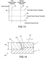
- Figure 13 shows a graph of pulse fluence 36 and absorbed energy density 133, where the absorbed energy density 133 is the total pulse energy 25 absorbed by the first and the second metal parts 1, 2 per unit surface area by the laser pulses 21.
- a pulse fluence 36 that is at least equal to the first pulse fluence threshold 131. This is in order to initiate coupling of the laser beam 6 to the metal surface 7, and the melting of the metal surface 7.
- the remaining pulses 21 should have a pulse fluence that is at least equal to the second pulse fluence threshold 132.
- the second pulse fluence threshold 132 can be substantially less than the first pulse fluence threshold 131.
- the second pulse fluence threshold 132 can be between two and ten times smaller than the first pulse fluence threshold 131. As each of the pulses 121 is absorbed, they contribute to the absorbed energy density 133.
- the absorbed energy density 133 absorbed at each of the focussed locations 16 should be at least equal to the first energy density threshold 134 at which the laser stake 17 begins to penetrate the second metal part 2, but less than the second energy density threshold 135 at which the weld 100 becomes unacceptably brittle.
- Figure 14 shows a key hold weld 140 that joins the first metal part 1 to the second metal part 2.
- the laser beam 6 not only melts the first and the second metal parts 1, 2 to form molten metal 143, but also produces vapour (not shown).
- the dissipating vapour exerts pressure on the molten metal 143 and partially displaces it.
- the result is a deep, narrow, vapour filled hole called the keyhole 141.
- Such a process may be involved in the formation of the heat stakes 17 in the apparatus and method of the invention.
- the key hole 141 is surrounded by the molten metal 143, and moves with the laser beam 6 in the direction 142 that the laser beam 6 is scanned.
- the molten metal 143 solidifies behind the key hole 141 as it moves, forming a weld seam 144.
- the weld seam 144 is deep and narrow.
- the weld depth 145 may be up to ten times greater than the weld width 151 shown with reference to Figure 15 .
- the laser beam 6 is absorbed with high efficiency in the key hole 141 as it is reflected multiple times.
- the apparatus and method of the invention extend to the case in which the heat stake 17 forms a continuous weld 156, as shown with reference to Figure 15 .
- the controller 12 has controlled the scanner 4 to scan the laser beam 6 in the spiral 110 shown with reference to Figure 10 such that successive focussed spots 16 shown with reference to Figure 17 overlap.
- the focussed spots 16 have resulted in the heat stake 17 that is continuous in the direction of the spiral arms 115, but which is at least partially separate in a radial direction 157.
- the radial direction 157 can be the direction 108 in Figure 1 .
- the weld 100 shown with reference to Figures 1 and 12 can be the continuous weld 156 of Figure 15 .
- the weld 100 may be formed with the key hole 141 described with reference to Figure 14 .
- the laser 3 was a nanosecond ytterbium-doped fibre laser, model SPI G4 70EP-Z manufactured by SPI Lasers UK Ltd of Victoria, England.
- the laser 3 is a master oscillator power amplifier having excellent control over the laser parameters shown in Figure 2 , namely the peak power 22, the average power 23, the pulse shape 24, the pulse energy 25, the pulse width 26, and the pulse repetition frequency F R 27.
- the scanner 4 was a galvanometer-scanner model Super Scan II manufactured by Raylase of Kunststoff, Germany with a 10mm beam aperture (not shown).
- the controller 12 comprised a desktop computer with a Windows 8 operating system on which SCAPS scanner application software licensed by SCAPS GmbH of Munich, Germany was used to program, operate, and store the code for the scanner 4 for steering the laser beam 6.
- the lens 5 was a 163mm focal length F-theta lens.
- the collimator 15 had a 75mm focal length.
- the lens 5, the collimator 15, and the scanner 4 were configured to form and translate the laser beam 6 onto the surface 7 of the first metal part 1 with a focused spot 16 having a spot size 34 of 40 ⁇ m and an area 35 of 1.256 x 10 -5 cm 2 .
- the first metal part 1 was copper grade C110 with a 150 ⁇ m thickness
- the second metal part 2 was aluminium grade 5052 with a 500 ⁇ m thickness.
- the pulse shape 24, the pulse energy 25, the pulse width 26, and the pulse fluence 36 it was decided to scan the laser beam 6 at a linear speed of 50mm/s over the metal surface 7 and with the distance 161 (shown with reference to Figure 17 ) between successive of the focussed spots 16 of 0.7 ⁇ m (measured centre to centre). This corresponds to the pulse repetition frequency 27 of 70kHz.
- the appropriate control parameters were then fed into the controller 12 and the laser 3 set up accordingly,
- the laser beam 6 was repetitively pulsed at the pulse repetition frequency 27 of 70kHz, and scanned over the metal surface 7 in the spiral 110 shown with reference to Figure 10 .
- the spiral was formed with a 50mm/s linear speed.
- the total lengh of the spiral 110 was 15.8 mm, and was formed from the first location 111 to the second location 112.
- the diameter 122 of the weld 100 was 1 mm.
- the pulse width 26 was 115 ns at full width half maximum FWHM and 520 ns at 10% of instantaneous peak power 22.
- Total pulse energy 25 was 1 mJ with an average power 23 of 70 W and a peak power 22 of 5 kW.
- Each laser pulse 21 had a peak power intensity of 3.98 x 10 +8 W/cm 2 with a pulse fluence 36 of 79.6 J/cm 2 .
- a shield gas mixture 106 was used of 50% Argon and 50% Helium supplied thorough a flow control regulator at 10 cubic feet per hour from a 6mm diameter copper nozzle 107 over the weld 100.
- the weld 100 that was formed is of the type shown in Figure 15 .
- the heat stakes 17 form a continuous line along the spiral, and are at least partially separated in a radial direction 157 across the spiral, corresponding to the direction 108 shown in Figure 1 .
- the weld pools 19 are continuous across the entire surface area of the weld 100, though as shown in Figure 1 , the surface of the weld 100 is not smooth. Observation of the welds 100 revealed aluminium colouring on its top surface, 103, indicating that the metals have mixed in the weld. The welds 100 were observed to be extremely strong for their size.
- the first metal part 1 was copper grade C110 with a 150 ⁇ m thickness
- the second metal part 2 was also copper grade C110 with a 150um thickness.
- the first metal part 1 was stainless steel grade 304 with a 250um thickness 104 and the second part 2 was grade stainless steel 304 with a 250um thickness 105.
- the pulse shape 24, the pulse energy 25, the pulse width 26, and the pulse fluence 36 it was decided to scan the laser beam 6 at a linear speed of 225mm/s over the metal surface 7 and with the distance 161 (shown with reference to Figure 17 ) between successive of the focussed spots 16 of 0.225 ⁇ m (measured centre to centre). This corresponds to the pulse repetition frequency 27 of 1MHz.
- the appropriate control parameters were then fed into the controller 12 and the laser 3 set up accordingly,
- the laser beam 6 was repetitively pulsed at the pulse repetition frequency 27 of 1MHz, and scanned over the metal surface 7 in the spiral 110 shown with reference to Figure 10 .
- the spiral 110 was formed with a 225 mm/s linear speed.
- the spiral 110 was formed from the first location 111 to the second location 112.
- the diameter 122 of the weld 100 was 1 mm.
- the pulse width 26 was 9 ns at full width half maximum FWHM and 9 ns at 10% of instantaneous peak power 22.
- Total pulse energy 25 was 7 ⁇ J with an average power 23 of 70 W and a peak power 22 of 8 kW.
- Each laser pulse 21 had a peak power intensity of 6.36 x 10 +8 W/cm 2 with a pulse fluence 36 of 5.6 J/cm 2 .
- a shield gas mixture 106 was used of 50% Argon and 50% Helium supplied thorough a low control regulator at 10 cubic feet per hour from a 6mm diameter copper nozzle 107 over the weld 100.
- the weld 100 that was formed is of the type shown in Figure 15 .
- the heat stakes 17 form a continuous line along the spiral, and are at least partially separated in a radial direction 157 across the spiral, corresponding to the direction 108 shown in Figure 1 .
- the weld pools 19 are continuous across the entire surface area of the weld 100, though as shown in Figure 1 , the surface of the weld 100 is not smooth.
- the weld 100 resembled a traditional lap weld, with excellent mixing of the metals, but almost negligible heat affected zone 72 (shown with reference to Figure 7 ).
- the continuous heat stakes 17 did extend from the weld, resulting in an uneven surface as shown in Figure 1 across the radius 157 of the weld 100.
- the extension of the heat stakes 17 from the weld 100 was substantially less than observed for the copper aluminium and copper copper welds of Examples 1 and 2 respectively.
- the welds 100 were observed to be extremely strong for their size.
Landscapes
- Physics & Mathematics (AREA)
- Optics & Photonics (AREA)
- Engineering & Computer Science (AREA)
- Plasma & Fusion (AREA)
- Mechanical Engineering (AREA)
- Laser Beam Processing (AREA)
Description
- This invention relates to a method for laser welding. The invention has particular application for welding dissimilar metals, bright metals, and for welding in consumer electronics, electronics packaging, energy storage, ornamental designs, and medical devices.
- Joining of bright metals such as gold, copper, aluminium, platinum and silver by laser welding in the near infrared spectrum (800nm to 2500nm) presents a challenge, as the surface of bright metals are highly reflective with poor absorbance. To overcome the surface reflectivity and initiate coupling of the laser's energy into the metal surface, it is necessary to use laser beams with high power densities.
- The function of the beam on a bright material approximates a discreet function with a very narrow operating window from beam hold-off (reflection) and absorption. At first the surface reflects substantially all of the laser light. However, once the surface reflectivity is overcome by sufficient laser intensity, a melt of the surface is initiated. The reflectivity then almost immediately transitions from its original highly reflective condition of more than 80% reflectivity to a lower value, which for some metals, can be less than 50% reflectivity. This causes the melt pool on the surface to grow extremely rapidly. It is consequently very difficult to control.
- The challenge is increased when welding thin and low mass sections. Such high power densities are often detrimental, leading to over penetration of the laser beam and resulting unreliable joints. Conversely, if near infrared lasers are operated at lower power densities with beam intensities at or just above the absorbance limits, then this generally results in weak or absent welds as a result of inconsistent and random coupling of the laser beam to the metal surface.
- The present preferred method of laser welding of copper and other bright metals such as gold and silver, involves the use of lasers that emit at visible green wavelengths. The most common lasers are frequency doubled 1064nm lasers that emit at 532nm. This is because the reflectivity of bright metals is usually significantly lower at 532nm than at near infrared wavelengths. The laser joining of bright metals with such lasers produces welds that are repeatable and consistent but at the cost of efficiency, complexity, and costs associated with frequency doubling. In some applications, it is necessary to combine a laser emitting at 532nm with a second laser at 1064nm in order to increase efficiency and productivity. Such dual wavelength systems require closed loop monitoring of the laser welding process using sophisticated beam monitoring and real time analysis in order to analyze and tailor the structure of the weld. Such diagnostic devices use video analysis of the back reflected light and the weld pool characteristics in order to provide feedback to the laser controller. These systems are complex and expensive.
- The use of green lasers has been adopted to perform weld joints of bright metals without specifically addressing the application of joining dissimilar metals. Conventional welding of dissimilar metals relies on specific control of the dilution of the metals at the interface and resulting thermal conditions to minimize mixing of the dissimilar metals which results in so-called intermetallics in the joint. A large intermetallic region is prone to fracture from stresses acting on the joint and the fracture propagates through the entire joint until failure.
- Laser welding with continuous wave and pulsed lasers is well known, with either a continuous weld front, or overlapping spot welds in which the weld forms a continuous seam. Defects in the materials caused by the welding process create weaknesses, and are unacceptable in the majority of applications. Pulsed welds are typically formed using microsecond and millisecond pulses, generating melt which resolidifies to form the weld. When welding dissimilar materials, the weld interface can contain intermetallics, which are a compound formed from the two materials being joined, and are typically brittle and undesirable in nature, and the weld can therefore break along this intermetallic layer.
-
United States Patent No. US 8,378,255 describes a laser beam irradiation apparatus which can accurately perform a linear welding. A series of spot welds are formed using a flash pumped YAG laser. The shape of the cross section of the laser beam is rectangular. - German patent application,
DE 10 2012 008 940 describes a method for joining at least two workpieces of identical or dissimilar metallic materials to a component by means of a continuously emitting laser beam by forming a weld along a joining surface by partially absorbing the laser beam in an area of the joining surface and a molten bath. A key hole is formed in the workpiece, and the key hole is oscillated in a circular motion when forming the weld. -
- Japanese patent application,
JP 2002 316282 A - There is a need for a simpler solution for joining bright and dissimilar metals and alloys without problems caused in the joint interface. The method should be able to produce consistent and predictive results on each joint. The resulting weld should have no reliability issues associated with intermetallics.
- There is a need for an apparatus and method for laser welding that avoids the aforementioned problems.
- The invention provides a method for laser welding a first metal part to a second metal part, which method comprises: placing the first metal part on the second metal part; providing a laser arranged to emit a laser beam in the form of laser pulses that have pulse widths in the range 1ns to 1000ns; providing a scanner for scanning the laser beam with respect to a metal surface of the first metal part; providing an objective lens for focusing the laser pulses onto the metal surface; providing a controller that is adapted to control the scanner such it moves the laser beam with respect to the metal surface, causing the laser to emit the laser pulses, focusing the laser pulses that have the pulse widths in the range 1ns to 1000ns with a spot size and a pulse fluence that cause the formation of a plurality of melt pools in the first metal part and heat stakes in the second metal part, wherein each heat stake extends from a different one of the melt pools and has a distal end, adapting the controller to space the focussed spots apart by a distance that is small enough to cause the melt pools to overlap and that is large enough to ensure the distal end of the heat stakes are distinct and separate from each other in at least one direction, and wherein the first metal part has a reflectivity greater than 80% at a wavelength emitted by the laser.
- The invention is particularly attractive because the weld can be formed from two dissimilar metals, one of which can be a bright metal, and can be formed through direct interaction between the materials and a laser beam. The metals can also have different melting points. The resulting weld is robust, repeatable, can be electrically conductive, and has no weaknesses caused by intermetallics.
- The spot size may be between 25µm and 100µm. The spot size may be between 30µm and 60µm.
- The laser may be configured to provide a pulse energy of 10mJ or less. The pulse energy may be 1mJ or less.
- The laser may provide between ten to one hundred pulses on the focussed spot.
- The laser weld may be autogenous.
- The heat stake may have a width that is less than or equal to half its depth.
- The first metal part may be coated.
- The first metal part may comprise multiple layers.
- The second metal part may comprise multiple layers.
- The first metal part and the second metal part may be formed from the same metal. The first metal part and the second metal part may be formed from different metals.
- The first metal part may comprise copper or a copper alloy.
- The first metal part may comprise a metal selected from the group comprising copper, aluminium, gold, silver, platinum, nickel, titanium, stainless steel, and an alloy containing one of the preceding metals such as bronze, brass, nickel-titanium, and amorphous alloys.
- The first metal part may have a reflectivity greater than 80%.
- The first metal part may melt when exposed to a pulse energy of 10mJ or less.
- When the first metal part comprises copper, the second metal part may comprise nickel plated steel. When the first metal part comprises aluminium, the second metal part may comprise steel.
- The first metal part may have a thickness in a weld region of no more than 2mm. The thickness may be less than 1mm. The thickness may be less than 0.5mm.
- The second metal part may have a thickness in a weld region of at least 100µm. The thickness of the second metal part in the weld region may be less than 0.5mm.
- A Young's modulus of the first metal part may be less than a Young's modulus of the second metal part.
- The first metal part may comprise a first metal and the second metal part may comprise a second metal, and the first metal may be substantially more ductile than the second metal.
- The heat stakes may be in the form of a spiral.
- The distance may be such that the focussed spots overlap with each other in at least one direction.
- Examples of articles that can be produced are beverage cans, tabs on beverage cans, mobile phones, tablet computers, televisions, machinery, and jewellery.
- Embodiments of the invention will now be described solely by way of example and with reference to the accompanying drawings in which:
-
Figure 1 shows apparatus for use in the method according to the present invention; -
Figure 2 shows a pulsed laser waveform; -
Figure 3 shows a laser beam that has been focussed onto a surface; -
Figure 4 shows a heat stake; -
Figure 5 shows a first metal part that is coated with a coating; -
Figure 6 shows a first metal part that comprises multiple layers; -
Figure 7 shows a prior art weld not according to the present invention; -
Figure 8 shows a weld according to the present invention that comprises a heat affected zone; -
Figure 9 shows a first metal part in the form of a tab welded to a second metal part; -
Figure 10 shows a welding trajectory in the form of a spiral; -
Figure 11 shows a weld in the form of a spiral comprising individual heat stakes; -
Figure 12 shows a first metal part joined to a second metal part using three welds; -
Figure 13 shows a graph of pulse fluence versus absorbed energy density; -
Figure 14 shows a key hole weld; -
Figure 15 shows a weld in the form of a continuous spiral; -
Figure 16 shows two separated focussed laser spots; and -
Figure 17 shows two overlapping focussed laser spots. -
Figure 1 shows apparatus for laser welding afirst metal part 1 to asecond metal part 2, which apparatus comprises alaser 3, ascanner 4, anobjective lens 5 and acontroller 12. Thelaser 3 emits alaser beam 6 in the form oflaser pulses 21. Thelaser beam 6 is shown being delivered to thescanner 4 via anoptical fibre cable 14 and acollimation optic 15. Thecollimation optic 15 expands and collimates thelaser beam 6 and inputs thelaser beam 6 into thescanner 4. Thescanner 4 is for moving the laser beam with respect to ametal surface 7 of thefirst metal part 1. Theobjective lens 5 focuses thelaser beam 6 onto themetal surface 7. Thecontroller 12 controls thescanner 4 such that it moves thelaser beam 6 with respect to themetal surface 7 to form a plurality of focussedspots 16 on themetal surface 7. - As shown with reference to
Figure 2 , thelaser pulses 21 can be characterized by aninstantaneous peak power 22, anaverage power 23, apulse shape 24, apulse energy 25, apulse width 26, and a pulserepetition frequency F R 27. It is important to select thelaser 1 such thatsufficient peak power 22 can be obtained to overcome the reflectivity of themetal surface 7 in order to ensure sufficient coupling of thepulse energy 25 with themetal surface 7 is achieved in order to melt themetal surface 7. -
Figure 3 shows aspot 31 having aspot size 34 formed by focussing thelaser beam 6 onto themetal surface 7. Theoptical intensity 32 is the power per unit area of thelaser beam 6. Theoptical intensity 32 varies across the radius of thespot 31 from apeak intensity 39 at its centre, to a 1/e2 intensity 33 and to zero. Thespot size 34 is typically taken as the 1/e2 diameter of thespot 31, which is the diameter at which theoptical intensity 32 falls to the 1/e2 intensity 33 on either side of thepeak intensity 39. Thearea 35 of thespot 31 is typically taken as the cross-sectional area of thespot 31 within the 1/e2 diameter. -
Pulse fluence 36 is defined as the energy per unit area of thespot 31 on thesurface 7. Pulse fluence is typically measured in J/cm2, and is an important parameter for laser welding because weld quality is highly influenced by thepulse fluence 36. Theoptimum pulse fluence 36 for a particular weld varies between different materials and material thicknesses. Theoptimum pulse fluence 36 for welding a metal piece part can be determined through experimentation. - Referring again to
Figure 1 , the apparatus focuses thelaser pulses 21 with aspot size 34 and apulse fluence 36 that causes the formation of a plurality of melt pools 19 in thefirst metal part 1 andheat stakes 17 in thesecond metal part 2. Eachheat stake 17 extends from a different one of the melt pools 19 and has adistal end 101. Thecontroller 12 controls thescanner 4 such that the focussedspots 16 are spaced apart by adistance 18 that is small enough to cause the melt pools 19 to overlap and that is large enough to ensure the distal ends 101 of the heat stakes 17 are distinct and separate from each other in at least onedirection 108. - Each
heat stake 17 is formed by at least one of thepulses 21, the number ofpulses 21 being dependent on thepulse fluence 36. Ten to one hundredpulses 21 are typically used for a laser with1mJ pulse energy 25. Thedistance 18 between the centres of the focussedspots 16 will approximate the distance between the centres of the respective heat stakes 17. Thecontroller 12 can cause thescanner 4 to hold the focussedspot 16 still during the formation of each of the heat stakes 17. Alternatively, thecontroller 12 can cause thescanner 4 to dither the focussedspot 16 during the formation of each of the heat stakes 17, preferably by an amount less than thedistance 18. Thedistance 18 is typically 20µm to 150µm, and preferably 40µm to 100µm. - The overlapping melt pools 19 and the heat stakes 17 form a
composite weld 100. For clarity,Figure 1 shows the focussedspots 16 as black circles, and theweld 100 in cross section within a three dimensional depiction. The melt pools 19 are shown melted together without boundaries between them, and an interface is shown between the melt pools 19 and the heat stakes 17. Metallurgical studies have demonstrated that both the melt pools 19 and the heat stakes 17 may comprise material that is from bothfirst metal part 1 and thesecond metal part 2. Good mixing of the metals can be achieved. There is generally no well defined boundary between the melt pools 19 and the heat stakes 17. The distal ends 101 of the heat stakes 17 are shown as ending in a sharp point. However this is not necessarily so; the distal ends 101 may be substantially curved and may be fragmented such that they have more than one end. - Successive focussed laser spots 16 may be separated as shown in
Figure 16 such that theseparation 161 between the centres of the laser spots 16 is greater than thespot size 34. Alternatively, successive focussed laser spots 16 may overlap as shown inFigure 17 such that theseparation 161 is less than thespot size 34. InFigures 16 and 17 , the focussedlaser spot 16 may represent asingle laser pulse 21 ormultiple laser pulses 21. - By "distinct and separate from each other", it is meant that the distal ends 101 of the heat stakes 17 do not form a substantially smooth weld in all directions; the heat stakes 17 may be at least partially separate from each other in at least one
direction 108. Alternatively, the heat stakes 17 may be at least partially separate from each other in all directions substantially parallel to themetal surface 7. By "weld" it is meant a connection made by welding or joining. - A
shield gas 106 may be applied over theweld 100 from agas supply 107 in order to prevent theweld 100 oxidising or to keep theweld 100 clean.. Theshield gas 106 can be argon, helium, nitrogen, or other gases commonly used in laser welding. Theshield gas 106 may be mixtures of the aforementioned gases. Thegas supply 107 may comprise a gas bottle, a nozzle, and a flow control regulator. - The
weld 100 has a substantially jagged surface at the distal ends 101 of the heat stakes 17. This is in direct contrast with conventional welding practice in which a smooth distal end of the weld is thought to be advantageous. A weld line that is not smooth is believed to be a cause for concern in the prior art. - The apparatus is preferably such that the
laser pulses 21 are in synchronism with acontrol signal 13 used to control thescanner 4. This may be achieved by using a synchronisation signal into thecontroller 12, or by adapting thecontroller 12 such that the controller also controls thelaser 3. - The
scanner 4 can be the galvanometric scan head shown inFigure 1 . Alternatively or additionally, thescanner 4 can be a moveable two-dimensional or three-dimensional translation stage, or a robot arm. Thescanner 4 is shown as comprising afirst mirror 8 for moving thelaser beam 6 in afirst direction 10, and asecond mirror 9 for scanning thelaser beam 6 in asecond direction 11. The first and thesecond mirrors scanner 4 and theobjective lens 5 may be part of a processing optics known by persons skilled in the art. The processing optic may have additional optical elements like tiled mirrors, additional focus control and/or beam shaping optics. - The
laser 3 can be a fibre laser, a solid state rod laser, a solid state disk laser, or a gas laser such as a carbon dioxide laser. Thelaser 3 can be a nanosecond laser. Thelaser 3 is preferably a rare-earth-doped nanosecond pulsed fibre laser, such as a ytterbium doped fibre laser, an erbium-doped (or erbium ytterbium doped) fibre laser, a holmium-doped fibre laser, or a thulium doped fibre laser. These lasers emit laser radiation in the 1µm, 1.5µm, 2µm and 2µm wavelength windows respectively. By a nanosecond pulsed laser, it is meant a laser that can emit pulses havingpulse widths 26 in the range 1ns to 1000ns. Such lasers may also be able to emit shorter pulses, and longer pulses, and may also be able to emit continuous wave radiation. Such lasers are different from prior art millisecond lasers that are conventionally used for welding. Millisecond lasers can generally form a weld by emitting a single pulse. - A method according to the invention and for laser welding the
first metal part 1 to thesecond metal part 2, will now be described solely by way of example and with reference toFigure 1 . The method comprises: placing thefirst metal part 1 on thesecond metal part 2; providing thelaser 3 for emitting thelaser beam 6 in the form of thelaser pulses 21; providing thescanner 4 for moving thelaser beam 6 with respect to themetal surface 7 of thefirst metal part 1; focussing thelaser beam 6 onto themetal surface 7; providing thecontroller 12 that is adapted to control thescanner 4 such it moves thelaser beam 6 with respect to themetal surface 7, configuring the apparatus to focus thelaser pulses 21 with thespot size 34 and thepulse fluence 36 that cause the formation of the plurality of the melt pools 19 in thefirst metal part 1 and the heat stakes 17 in thesecond metal part 2, wherein eachheat stake 17 extends from a different one of the melt pools 19 and has adistal end 101, and adapting thecontroller 4 to space the focussedspots 16 apart by thedistance 18 that is small enough to cause the melt pools 19 to overlap and that is large enough to ensure the distal ends of the heat stakes 17 are distinct and separate from each other in at least onedirection 108. - The method may include the step of providing the
shield gas 106 and thegas supply 107, and applying theshield gas 106 over theweld 100. Theshield gas 106 can be argon, helium, nitrogen, or other gases commonly used in laser welding. Theshield gas 106 may be mixtures of the aforementioned gases. Thegas supply 107 may comprise a gas bottle, a nozzle, and a flow control regulator. - In the following, frequent reference will be made to "reflective metals", which is meant to mean metals having a reflectivity greater than 80% at an
emission wavelength 102 of thelaser 3 at the temperature at which thefirst metal part 1 is processed. - The
laser weld 100 formed by the apparatus or the method of the invention may be autogenous, that is, no other materials other than the first and thesecond metal parts - The
first metal part 1 may have athickness 104 in a region of theweld 100 of no more than 5mm. Thethickness 104 may be less than 2mm. Thethickness 104 may be less than 1mm. Thethickness 104 may be less than 0.5mm. Thesecond metal part 2 may have athickness 105 in the region of theweld 100. Thethickness 105 may be at least 100µm. Thethickness 105 may be less than 0.5mm. - Referring to
Figure 4 , theheat stake 17 may have awidth 41 that is at most half itsdepth 42. This is advantageous because it allows theheat stake 17 to penetrate further and may allow thefirst metal part 1 to grip thesecond metal part 2 better. - As shown in
Figure 5 , thefirst metal part 1 may comprise ametal part 51 which is coated with acoating 52. Thecoating 52 may be a metal plating such as nickel or chrome, or may be a chemically-induced coating formed by processes such as anodization. Thecoating 52 may be a polymer coating. - The
first metal part 1 may comprisemultiple layers 61 as shown with reference toFigure 6 . Themultiple layers 61 may be folded sheets of the same metal, layers of the same metal, or layers of different metals. Alternatively or additionally, thesecond metal part 2 may comprisemultiple layers 62. Themultiple layers 62 may be folded sheets of the same metal, layers of the same metal, or layers of different metals. Thelayers 61 may comprise the same metal as thelayers 62, or different metals. Theweld 100 is shown joining thefirst metal part 1 to thesecond metal part 2. Theweld 100 is shown partially penetrating thesecond metal part 2. -
Figure 7 shows alaser weld 70 between thefirst metal part 1 and thesecond metal part 2 using prior art techniques, including for example, laser welding with a green laser using a single high-energy pulse of 100mJ or more. Theweld 70 has a much larger mass than one of the individual melt pools 19 plus its associatedheat stake 17 shown with reference toFigure 1 , and consequently takes a longer period to cool down. This results in metallic mixing in aweld pool 75, the formation of an associatedboundary layer 71, and an area around theweld 70 that is affected by the heat but where the metals have not flowed - the so-called heat affected zone (HAZ) 72. The mechanical properties of the heat affectedzone 72 can be substantially degraded as a result of thermal heat tempering, which tempering should generally be minimized. The heat affectedzone 72 is generally visible (for example after etching with acid) on both thetop surface 73 of thefirst metal part 1 and thebottom surface 74 of thesecond metal part 2. - The
boundary layer 71, when welding steel to steel, can result in carbon formation along grain boundary interfaces, thereby providing a pathway for fracturing theweld 100. Similarly, theboundary layer 71 when welding dissimilar metals may comprise intermetallics with a grain structure reflecting the cooling time from fusion to solidification. Such intermetallics are often brittle in nature, and therefore represent a weak point in theweld 70. Thus the existence of thelarge boundary layer 71 and the heat affectedzone 72 are not desirable in either the welding of similar metals or the welding of dissimilar metals. - Whether the
weld 70 is formed from similar metals or dissimilar metals, the mechanical properties of the material comprising theweld pool 75 are likely to be weaker than the properties of the base materials that comprise thefirst metal part 1 and thesecond metal part 2. Heat affectedzones 72 are also of a concern if they affect the appearance or chemical composition of the first andsecond metal parts - The problems associated with
intermetallic layers 71 and heat affectedzones 72 increase when welding thin sheet metals. Other issues concerning the time taken for welds to cool down include damage to coatings such as polymers on the first andsecond metal parts -
Figure 8 depicts a top view of theweld 100 shown inFigure 1 . A heat affectedzone 81 is usually visible (possibly after chemical etching). However, with proper selection of thelaser 1 and the laser pulse parameters shown with reference toFigures 2 and 3 , there is generally no heat affected zone visible on the bottom surface. This is because the heat stakes 17 each have significantly less mass than theweld 70, and consequently cool more rapidly. Similarly, there is little or no evidence ofintermetallic layers 71 surrounding the heat stakes 17. The lack of intermetallic layers and a heat affected zone that extends through thesecond metal part 2 provide great advantages over prior art welding techniques. - The
second metal part 2 shown inFigure 9 may comprise ametal part 92 which is coated with acoating 93. Thecoating 93 may be a metal plating such as nickel or chrome, or may be a chemically-induced coating such as an anodization. Thefirst metal part 1 may be atab 91 such as found in beverage cans. Thetab 91 is shown welded to thesecond metal part 2 with theweld 100. - Beverage cans are often made from thin sheets of aluminium that are less than 250µm in thickness. In a beverage can, the
coating 93 would be a polymer coating usually applied before theweld 100 is formed. It is important that the method of forming theweld 100 does not degrade thecoating 93. The apparatus and method of the present invention achieves this by virtue of the heat stakes 17, shown with reference toFigure 1 , as there is less heat generated in thesecond metal part 2 compared to a prior art weld. - Referring again to
Figure 1 , thefirst metal part 1 and thesecond metal part 2 may be formed from the same metal. The metal may be aluminium or copper, or alloys thereof. Alternatively, thefirst metal part 1 and thesecond metal part 2 may be formed from different metals. - The
first metal part 1 may comprise copper or a copper alloy. - The
first metal part 1 may comprise a metal selected from the group comprising copper, aluminium, gold, silver, platinum, nickel, titanium, stainless steel, and an alloy containing one of the preceding metals such as bronze, brass, nickel-titanium, and amorphous alloys. - The
first metal part 1 may have areflectivity 103 greater than 80% at the wavelength (A) 102 emitted by thelaser 3.Figure 1 shows thewavelength 102 being 1060nm; this is intended to be non-limiting. Ytterbium pulsed fibre lasers are especially attractive to use as thelaser 3; these emit in the wavelength range from approximately 1030 nm to approximately 1100nm. Thelaser 3 can also be an erbium doped, or erbium ytterbium co-doped fibre laser, each emitting at around 1550nm, or a holmium or thulium doped fibre laser emitting at around 2000nm. The use of lasers emitting at 1500nm and 2000nm provide eye safety advantages that are important in certain applications. There are also many other laser types that emit in the near infra-red wavelengths. - The
spot size 34 may be 25µm to 100µm, and preferably 30µm to 60µm. - The
first metal part 1 may melt when exposed to apulse energy 25 of 10mJ or less. Thepulse energy 25 may be 4 mJ or less. Thepulse energy 25 may be 1mJ or less. The pulse energy may be 100µJ or less. The pulse energy may be 10µJ or less. Thicker materials requirelarger pulse energies 25 than thinner materials. - The
first metal part 1 may comprise copper. Thesecond metal part 2 may comprise nickel plated steel. - The
first metal part 1 may comprise aluminium. Thesecond metal part 2 may comprise steel. - The
first metal part 1 may be defined by a Young's modulus which is less than a Young's modulus of thesecond metal part 2. - The
first metal part 1 may comprise a first metal and thesecond metal part 2 may comprise a second metal. The Young's modulus of the first metal may be less than a Young's modulus of the second metal. Advantageously, the first metal may be substantially more ductile than the second metal. This has important advantages if theweld 100 is repeatedly strained since the heat stakes 17 will be more resistant to metal fatigue resulting in failure. - The heat stakes 17 are preferably formed in a line that is not linear in order to increase the shear strength of the
weld 100. For example, the heat stakes 17 may be formed in the form of a spiral 110 as shown with reference toFigure 10 . Thespiral 110 is formed by causing thecontroller 12 to move thelaser beam 6 in atrajectory 117 that is in the form of thespiral 110, and which has afirst location 111 shown as being in the inside of the spiral, and asecond location 112, shown as being on the outside of the spiral. It is generally preferred that thespiral trajectory 117 starts from thefirst location 111, but may alternatively start from thesecond location 112.Figure 11 shows a cross section through the resultingweld 116, which cross section is beneath the overlapping melt pools 19, shown with reference toFigure 1 . As shown with reference toFigure 16 , the successive focussedspots 16 are separated by thedistance 161 which is greater than thespot size 34. It is preferred that thelaser 3 is pulsed at least once, and preferably between ten to one hundred times, on each of the focussed spots 16. By this means, it is possible to control the amount of heat being injected into each part of theweld 116 very precisely, thus allowing the strength of theweld 116 to be optimised. The choice of whether to commence from thefirst location 111 or thesecond location 112 can be determined experimentally from the strength of the resultingweld 116. InFigure 11 , adistance 113 is shown between the centres of two of the heat stakes 17, and adistance 114 between centres of adjacentspiral arms 115. Thedistance 113 can be less than 100µm, less than 75µm, and preferably less than 50µm. Thedistance 114 can be less than 250µm, less than 200µm, less than 150µm, and preferably less than 100µm. Optimizing thedistances -
Figure 12 shows thefirst metal part 1 welded to thesecond metal part 2 with three of thewelds 100. Thewelds 100 can be thespiral weld 116 shown with reference toFigure 11 . Thewelds 100 can have adiameter 122 of between 0.5 to 2mm, and preferably between 0.75 to 1.5mm. By using a plurality of thewelds 100, more strength and rigidity is obtained. -
Figure 13 shows a graph ofpulse fluence 36 and absorbedenergy density 133, where the absorbedenergy density 133 is thetotal pulse energy 25 absorbed by the first and thesecond metal parts laser pulses 21. In order to initiate theweld 100 shown with reference toFigure 1 , it is necessary to use apulse fluence 36 that is at least equal to the firstpulse fluence threshold 131. This is in order to initiate coupling of thelaser beam 6 to themetal surface 7, and the melting of themetal surface 7. Once themetal surface 7 has begun to melt, the remainingpulses 21 should have a pulse fluence that is at least equal to the secondpulse fluence threshold 132. The secondpulse fluence threshold 132 can be substantially less than the firstpulse fluence threshold 131. For afirst metal part 1 with high reflectivity, that is, reflectivities at the wavelength of thelaser beam 6 greater than 80%, the secondpulse fluence threshold 132 can be between two and ten times smaller than the firstpulse fluence threshold 131. As each of the pulses 121 is absorbed, they contribute to the absorbedenergy density 133. The absorbedenergy density 133 absorbed at each of thefocussed locations 16 should be at least equal to the firstenergy density threshold 134 at which thelaser stake 17 begins to penetrate thesecond metal part 2, but less than the secondenergy density threshold 135 at which theweld 100 becomes unacceptably brittle. It can be seen that by varying the pulse parameters shown with reference toFigures 2 and 3 , the number of pulses, and thedistances 18 between focussedspots 16, there is a great controllability of theweld 100, and moreover, greater control over its formation, and therefore mechanical properties, than prior art techniques. -
Figure 14 shows akey hold weld 140 that joins thefirst metal part 1 to thesecond metal part 2. In this process, thelaser beam 6 not only melts the first and thesecond metal parts molten metal 143, but also produces vapour (not shown). The dissipating vapour exerts pressure on themolten metal 143 and partially displaces it. The result is a deep, narrow, vapour filled hole called thekeyhole 141. Such a process may be involved in the formation of the heat stakes 17 in the apparatus and method of the invention. - The
key hole 141 is surrounded by themolten metal 143, and moves with thelaser beam 6 in thedirection 142 that thelaser beam 6 is scanned. Themolten metal 143 solidifies behind thekey hole 141 as it moves, forming aweld seam 144. Theweld seam 144 is deep and narrow. Theweld depth 145 may be up to ten times greater than theweld width 151 shown with reference toFigure 15 . Thelaser beam 6 is absorbed with high efficiency in thekey hole 141 as it is reflected multiple times. - The apparatus and method of the invention extend to the case in which the
heat stake 17 forms acontinuous weld 156, as shown with reference toFigure 15 . Here thecontroller 12 has controlled thescanner 4 to scan thelaser beam 6 in thespiral 110 shown with reference toFigure 10 such that successive focussedspots 16 shown with reference toFigure 17 overlap. The focussedspots 16 have resulted in theheat stake 17 that is continuous in the direction of thespiral arms 115, but which is at least partially separate in aradial direction 157. Theradial direction 157 can be thedirection 108 inFigure 1 . As shown by the cross section inFigure 1 , it is preferred that the melt pools 19 overlap. Theweld 100 shown with reference toFigures 1 and12 can be thecontinuous weld 156 ofFigure 15 . Theweld 100 may be formed with thekey hole 141 described with reference toFigure 14 . - The method of the invention will now be described with reference to the apparatus and method described with reference to
Figure 1 and to the non-limiting examples set out below. Thelaser 3 was a nanosecond ytterbium-doped fibre laser, model SPI G4 70EP-Z manufactured by SPI Lasers UK Ltd of Southampton, England. Thelaser 3 is a master oscillator power amplifier having excellent control over the laser parameters shown inFigure 2 , namely thepeak power 22, theaverage power 23, thepulse shape 24, thepulse energy 25, thepulse width 26, and the pulserepetition frequency F R 27. Thescanner 4 was a galvanometer-scanner model Super Scan II manufactured by Raylase of Munich, Germany with a 10mm beam aperture (not shown). Thecontroller 12 comprised a desktop computer with aWindows 8 operating system on which SCAPS scanner application software licensed by SCAPS GmbH of Munich, Germany was used to program, operate, and store the code for thescanner 4 for steering thelaser beam 6. Thelens 5 was a 163mm focal length F-theta lens. Thecollimator 15 had a 75mm focal length. Thelens 5, thecollimator 15, and thescanner 4 were configured to form and translate thelaser beam 6 onto thesurface 7 of thefirst metal part 1 with afocused spot 16 having aspot size 34 of 40µm and anarea 35 of 1.256 x 10⁻⁵ cm2. - With reference to
Figure 12 , thefirst metal part 1 was copper grade C110 with a 150µm thickness, and thesecond metal part 2 was aluminium grade 5052 with a 500µm thickness. Following experimentation to determine thepeak power 22, thepulse shape 24, thepulse energy 25, thepulse width 26, and thepulse fluence 36, it was decided to scan thelaser beam 6 at a linear speed of 50mm/s over themetal surface 7 and with the distance 161 (shown with reference toFigure 17 ) between successive of the focussedspots 16 of 0.7µm (measured centre to centre). This corresponds to thepulse repetition frequency 27 of 70kHz. The appropriate control parameters were then fed into thecontroller 12 and thelaser 3 set up accordingly, Thelaser beam 6 was repetitively pulsed at thepulse repetition frequency 27 of 70kHz, and scanned over themetal surface 7 in thespiral 110 shown with reference toFigure 10 . The spiral was formed with a 50mm/s linear speed. The total lengh of thespiral 110 was 15.8 mm, and was formed from thefirst location 111 to thesecond location 112. Thediameter 122 of theweld 100 was 1 mm. Thepulse width 26 was 115 ns at full width half maximum FWHM and 520 ns at 10% ofinstantaneous peak power 22.Total pulse energy 25 was 1 mJ with anaverage power 23 of 70 W and apeak power 22 of 5 kW. Eachlaser pulse 21 had a peak power intensity of 3.98 x 10+8W/cm2 with apulse fluence 36 of 79.6 J/cm2. Ashield gas mixture 106 was used of 50% Argon and 50% Helium supplied thorough a flow control regulator at 10 cubic feet per hour from a 6mmdiameter copper nozzle 107 over theweld 100. Theweld 100 that was formed is of the type shown inFigure 15 . The heat stakes 17 form a continuous line along the spiral, and are at least partially separated in aradial direction 157 across the spiral, corresponding to thedirection 108 shown inFigure 1 . The weld pools 19 are continuous across the entire surface area of theweld 100, though as shown inFigure 1 , the surface of theweld 100 is not smooth. Observation of thewelds 100 revealed aluminium colouring on its top surface, 103, indicating that the metals have mixed in the weld. Thewelds 100 were observed to be extremely strong for their size. - With reference to
Figure 12 , thefirst metal part 1 was copper grade C110 with a 150µm thickness, and thesecond metal part 2 was also copper grade C110 with a 150um thickness. After experimentation, it was determined that the same process parameters could be used as described with reference to Example 1. The resulting welds were observed to be extremely strong for their size. - With reference to
Figure 12 , thefirst metal part 1 was stainless steel grade 304 with a250um thickness 104 and thesecond part 2 was grade stainless steel 304 with a250um thickness 105. Following experimentation to determine thepeak power 22, thepulse shape 24, thepulse energy 25, thepulse width 26, and thepulse fluence 36, it was decided to scan thelaser beam 6 at a linear speed of 225mm/s over themetal surface 7 and with the distance 161 (shown with reference toFigure 17 ) between successive of the focussedspots 16 of 0.225µm (measured centre to centre). This corresponds to thepulse repetition frequency 27 of 1MHz. The appropriate control parameters were then fed into thecontroller 12 and thelaser 3 set up accordingly, Thelaser beam 6 was repetitively pulsed at thepulse repetition frequency 27 of 1MHz, and scanned over themetal surface 7 in thespiral 110 shown with reference toFigure 10 . Thespiral 110 was formed with a 225 mm/s linear speed. Thespiral 110 was formed from thefirst location 111 to thesecond location 112. Thediameter 122 of theweld 100 was 1 mm. Thepulse width 26 was 9 ns at full width half maximum FWHM and 9 ns at 10% ofinstantaneous peak power 22.Total pulse energy 25 was 7 µJ with anaverage power 23 of 70 W and apeak power 22 of 8 kW. Eachlaser pulse 21 had a peak power intensity of 6.36 x 10+8 W/cm2 with apulse fluence 36 of 5.6 J/cm2. Ashield gas mixture 106 was used of 50% Argon and 50% Helium supplied thorough a low control regulator at 10 cubic feet per hour from a 6mmdiameter copper nozzle 107 over theweld 100. Theweld 100 that was formed is of the type shown inFigure 15 . The heat stakes 17 form a continuous line along the spiral, and are at least partially separated in aradial direction 157 across the spiral, corresponding to thedirection 108 shown inFigure 1 . The weld pools 19 are continuous across the entire surface area of theweld 100, though as shown inFigure 1 , the surface of theweld 100 is not smooth. Because of the different parameters being used, theweld 100 resembled a traditional lap weld, with excellent mixing of the metals, but almost negligible heat affected zone 72 (shown with reference toFigure 7 ). However, the continuous heat stakes 17 did extend from the weld, resulting in an uneven surface as shown inFigure 1 across theradius 157 of theweld 100. However the extension of the heat stakes 17 from theweld 100 was substantially less than observed for the copper aluminium and copper copper welds of Examples 1 and 2 respectively. Thewelds 100 were observed to be extremely strong for their size. - It is to be appreciated that the embodiments of the invention described above with reference to the accompanying drawings have been given by way of example only and that modifications and additional steps and components may be provided to enhance performance.
Claims (21)
- A method for laser welding a first metal part (1) to a second metal part (2), which method comprises:• placing the first metal part (1) on the second metal part (2),• providing a laser (3) arranged to emit a laser beam (6) in the form of laser pulses (21) that have pulse widths (26) in the range 1ns to 1000ns,• providing a scanner (4) for scanning the laser beam (6) with respect to a metal surface (7) of the first metal part (1),• providing an objective lens (5) for focusing the laser pulses (21) onto the metal surface (7),• providing a controller (12) that is adapted to control the scanner (4) such that it moves the laser beam (6) with respect to the metal surface (7),• causing the laser (3) to emit the laser pulses (21),• focusing the laser pulses (21) that have the pulse widths (26) in the range 1ns to 1000ns with a spot size (34) and a pulse fluence (36) that cause the formation of a plurality of melt pools (19) in the first metal part (1) and heat stakes (17) in the second metal part (2), wherein each heat stake (17) extends from a different one of the melt pools (19) and has a distal end (101),• adapting the controller (12) to space the focussed spots (16) apart by a distance (18) that is small enough to cause the melt pools (19) to overlap and that is large enough to ensure the distal end (101) of the heat stakes (17) are distinct and separate from each other in at least one direction (108), and• wherein the first metal part (1) has a reflectivity (103) greater than 80% at a wavelength (102) emitted by the laser (3).
- A method according to claim 1 wherein the spot size (34) is between 25µm and 100µm.
- A method according to claim 2 wherein the spot size (34) is between 30µm and 60µm.
- A method according to any one of claims 1 to 3 wherein the laser (3) is configured to provide a pulse energy (25) of 10mJ or less.
- A method according to claim 4 wherein the pulse energy (25) is 1mJ or less.
- A method according to any one of claims 1 to 5 wherein the laser (3) provides between ten to one hundred pulses on the focussed spot (34).
- A method according to any one of claims 1 - 6 wherein the laser weld is autogenous.
- A method according to any one of claims 1 - 7, wherein the heat stake (17) has a width (41) that is less than or equal to half its depth (42).
- A method according to any one of claims 1 - 8 wherein the first metal part (1) is coated.
- A method according to any one claims 1 - 9 wherein the first metal part (1) comprises multiple layers (61).
- A method according to any one of claims 1 - 10 wherein the second metal part (2) comprises multiple layers (62).
- A method according to any one of claims 1 - 11 wherein the first metal part (1) and the second metal part (2) are formed from different metals.
- A method according to any one of claims 1 - 12 wherein the first metal part (1) comprises a metal selected from the group comprising copper, aluminium, gold, silver, platinum, nickel, titanium, stainless steel, and an alloy containing one of the preceding metals.
- A method according to claim 13, wherein the first metal part (1) comprises aluminium and the second metal part (2) comprises steel.
- A method according to any one of claims 1 - 14, wherein the first metal part (1) has a thickness (104) in a weld region of no more than 2mm.
- A method according to claim 15 wherein the thickness (104) is less than 1mm.
- A method according to claim 16 wherein the thickness (104) is less than 0.5mm.
- A method according to any one of claims 1 - 17 wherein the second metal part (2) has a thickness (105) in a weld region of at least 100µm.
- A method according to claim 18 wherein the thickness (105) of the second metal part (2) in the weld region is less than 0.5mm.
- A method according to any one of claims 1 - 19 wherein the heat stakes (17) are in the form of a spiral (110).
- A method according to any one of claims 1 - 20 wherein the distance (18) is such that the focussed spots (16) overlap with each other in at least one direction (108).
Applications Claiming Priority (2)
| Application Number | Priority Date | Filing Date | Title |
|---|---|---|---|
| GBGB1502149.6A GB201502149D0 (en) | 2015-02-09 | 2015-02-09 | Apparatus and method for laser welding |
| PCT/GB2016/000029 WO2016128705A1 (en) | 2015-02-09 | 2016-02-08 | Apparatus and method for overlap laser welding |
Publications (3)
| Publication Number | Publication Date |
|---|---|
| EP3256284A1 EP3256284A1 (en) | 2017-12-20 |
| EP3256284C0 EP3256284C0 (en) | 2025-04-02 |
| EP3256284B1 true EP3256284B1 (en) | 2025-04-02 |
Family
ID=52746373
Family Applications (1)
| Application Number | Title | Priority Date | Filing Date |
|---|---|---|---|
| EP16708193.4A Active EP3256284B1 (en) | 2015-02-09 | 2016-02-08 | Method for overlap laser welding |
Country Status (7)
| Country | Link |
|---|---|
| US (1) | US10668565B2 (en) |
| EP (1) | EP3256284B1 (en) |
| JP (1) | JP6993879B2 (en) |
| KR (1) | KR102248769B1 (en) |
| CN (2) | CN208342006U (en) |
| GB (1) | GB201502149D0 (en) |
| WO (1) | WO2016128705A1 (en) |
Families Citing this family (35)
| Publication number | Priority date | Publication date | Assignee | Title |
|---|---|---|---|---|
| US10940562B2 (en) * | 2017-01-31 | 2021-03-09 | Nuburu, Inc. | Methods and systems for welding copper using blue laser |
| DE102016212057A1 (en) * | 2016-07-01 | 2018-01-04 | Bayerische Motoren Werke Aktiengesellschaft | Method for welding components |
| CN106346135A (en) * | 2016-11-04 | 2017-01-25 | 广东国玉科技有限公司 | Different material laser welding method |
| JP6484272B2 (en) * | 2017-03-17 | 2019-03-13 | 株式会社フジクラ | Laser processing apparatus and laser processing method |
| WO2019131828A1 (en) * | 2017-12-28 | 2019-07-04 | 株式会社フジクラ | Welding structure, wiring board equipped with metal piece, and welding method |
| DE102018102523B4 (en) * | 2018-02-05 | 2019-10-10 | Scansonic Mi Gmbh | Welding method and laser welding device for joining foil-like workpieces |
| US11504801B2 (en) * | 2018-08-24 | 2022-11-22 | Phoenix Laser Solutions | Bimetallic joining with powdered metal fillers |
| DE102018215069A1 (en) * | 2018-09-05 | 2020-03-05 | Robert Bosch Gmbh | Method for connecting individual film-shaped foils of a battery foil stack |
| JP7192363B2 (en) * | 2018-09-28 | 2022-12-20 | マツダ株式会社 | LASER WELDING METHOD AND LASER WELDING APPARATUS |
| JP7110907B2 (en) * | 2018-10-26 | 2022-08-02 | トヨタ自動車株式会社 | Lap welding method for dissimilar metal members |
| JP6989549B2 (en) * | 2019-03-13 | 2022-01-05 | フタバ産業株式会社 | Manufacturing method of the joint |
| US10926347B2 (en) * | 2019-03-25 | 2021-02-23 | Packless Industries | Autogenous submerged liquid diffusion welding of titanium |
| DE102019211581A1 (en) * | 2019-08-01 | 2021-02-04 | Trumpf Laser Gmbh | Process for welding a copper-aluminum connection |
| JP7305502B2 (en) * | 2019-09-26 | 2023-07-10 | 株式会社ダイヘン | Laser-arc hybrid welding equipment |
| CN111230298B (en) * | 2020-01-21 | 2023-03-21 | 中国科学院物理研究所 | Application of nanosecond laser and welding method of amorphous alloy material |
| CN115697622B (en) * | 2020-06-04 | 2026-04-14 | 古河电气工业株式会社 | Welding method, welding device, metal laminate, electric component, and electric product |
| DE102020214505A1 (en) | 2020-11-18 | 2022-05-19 | Robert Bosch Gesellschaft mit beschränkter Haftung | Device and method for connecting components |
| CN113199147A (en) * | 2021-04-21 | 2021-08-03 | 上海工程技术大学 | Laser deep melting spot welding process for aluminum/steel dissimilar metal |
| CN113290315A (en) * | 2021-05-12 | 2021-08-24 | 深圳市艾雷激光科技有限公司 | Method, apparatus, controller and readable storage medium for welding battery electrode |
| TWI834045B (en) * | 2021-06-25 | 2024-03-01 | 台達電子工業股份有限公司 | Laser welding system using dynamic light spot size and method thereof |
| CN114054957B (en) * | 2021-07-06 | 2025-03-11 | 武汉帝尔激光科技股份有限公司 | Laser welding method and system for dissimilar metal films |
| KR20230058754A (en) * | 2021-10-25 | 2023-05-03 | 주식회사 엘지에너지솔루션 | Cylindrical Battery Cell with Spiral Welding Part and Battery Module Comprising the Same |
| CN114346429A (en) * | 2021-12-27 | 2022-04-15 | 深圳泰德激光技术股份有限公司 | Thin material laser welding method |
| CN114406469B (en) * | 2022-03-03 | 2024-09-24 | 吉林大学 | Laser welding of steel and aluminum alloy using nickel-based high entropy alloy intermediate layer |
| CN114985924A (en) * | 2022-05-19 | 2022-09-02 | 深圳泰德激光技术股份有限公司 | A kind of laser welding method and component of thin material |
| JP2024013085A (en) * | 2022-07-19 | 2024-01-31 | 矢崎総業株式会社 | Metal plate joining method, busbar module manufacturing method, and battery module manufacturing method |
| CN115476056B (en) * | 2022-10-14 | 2026-02-10 | 北京慧骨医学科技有限公司 | Laser beam spot determination method, device, electronic equipment and storage medium |
| CN116275521A (en) * | 2023-04-03 | 2023-06-23 | 合肥国轩高科动力能源有限公司 | A kind of welding method of battery surge plate |
| GB202312217D0 (en) * | 2023-08-09 | 2023-09-20 | Trumpf Laser Uk Ltd | A weld |
| CN117182277A (en) * | 2023-09-26 | 2023-12-08 | 北京星航机电装备有限公司 | A welding structure and method for dissimilar metal structural parts |
| CN117182368A (en) * | 2023-09-26 | 2023-12-08 | 北京星航机电装备有限公司 | A method to prevent composite welding cracks of dissimilar metal structural parts |
| CN117564468B (en) * | 2023-11-13 | 2024-07-05 | 东北电力大学 | Pulse laser welding method for metal material sheet with targeting cooperative preheating |
| DE102023004942A1 (en) * | 2023-11-30 | 2025-06-05 | Mercedes-Benz Group AG | Process for laser beam welding of components |
| JP2025179428A (en) * | 2024-05-28 | 2025-12-10 | リョービ株式会社 | Laser welding method for dissimilar metals and dissimilar metal joint |
| CN119897596B (en) * | 2025-04-01 | 2025-08-05 | 浙江摩克激光智能装备有限公司 | Dissimilar metal welding method, welding system and copper substrate |
Citations (1)
| Publication number | Priority date | Publication date | Assignee | Title |
|---|---|---|---|---|
| JP2002316282A (en) * | 2001-04-18 | 2002-10-29 | Matsushita Electric Ind Co Ltd | Laser processing method and apparatus |
Family Cites Families (57)
| Publication number | Priority date | Publication date | Assignee | Title |
|---|---|---|---|---|
| US4873415A (en) * | 1988-02-02 | 1989-10-10 | Raycon Corporation | Method for welding galvanized material |
| US5502292A (en) * | 1994-08-04 | 1996-03-26 | Midwest Research Institute | Method for laser welding ultra-thin metal foils |
| US6285002B1 (en) | 1999-05-10 | 2001-09-04 | Bryan Kok Ann Ngoi | Three dimensional micro machining with a modulated ultra-short laser pulse |
| JP4659300B2 (en) * | 2000-09-13 | 2011-03-30 | 浜松ホトニクス株式会社 | Laser processing method and semiconductor chip manufacturing method |
| TW516981B (en) * | 2000-12-22 | 2003-01-11 | Koninkl Philips Electronics Nv | Method of laser welding |
| AU2002253572A1 (en) * | 2001-04-27 | 2002-11-11 | Honda Giken Kogyo Kabushiki Kaisha | Method and appratus for laser beam welding of overlapping sheets |
| FR2830477B1 (en) * | 2001-10-09 | 2004-02-06 | Usinor | METHOD AND DEVICE FOR COVERING WELDING USING A HIGH ENERGY DENSITY BEAM OF TWO COATED SHEETS |
| US20050155956A1 (en) | 2002-08-30 | 2005-07-21 | Sumitomo Heavy Industries, Ltd. | Laser processing method and processing device |
| JP2004255435A (en) | 2003-02-27 | 2004-09-16 | Suzuki Motor Corp | Laser welding apparatus and method |
| US6906281B2 (en) * | 2003-03-03 | 2005-06-14 | Dana Corporation | Method for laser welding of metal |
| ATE375023T1 (en) * | 2003-04-29 | 2007-10-15 | Spi Lasers Uk Ltd | LASER DEVICE FOR MATERIAL PROCESSING |
| US7154064B2 (en) * | 2003-12-08 | 2006-12-26 | General Motors Corporation | Method of improving weld quality |
| EP1547719A3 (en) | 2003-12-26 | 2009-01-28 | Semiconductor Energy Laboratory Co., Ltd. | Laser irradiation apparatus, laser irradiation method, and method for manufacturing crystalline semiconductor film |
| DE102004005358B4 (en) * | 2004-02-03 | 2007-03-22 | Daimlerchrysler Ag | Process for the laser processing of coated sheets and coated sheet metal |
| JP4200177B2 (en) * | 2004-08-06 | 2008-12-24 | 浜松ホトニクス株式会社 | Laser processing method and semiconductor device |
| US20090223940A1 (en) * | 2004-08-09 | 2009-09-10 | Nec Corporation | Different metallic thin plates welding method, bimetallic thin plates jointing element, electric device, and electric device assembly |
| US20090283505A1 (en) * | 2005-07-13 | 2009-11-19 | Dr Industries | Interface suspension for alloy based laser welding |
| US7626138B2 (en) * | 2005-09-08 | 2009-12-01 | Imra America, Inc. | Transparent material processing with an ultrashort pulse laser |
| US9138913B2 (en) * | 2005-09-08 | 2015-09-22 | Imra America, Inc. | Transparent material processing with an ultrashort pulse laser |
| US8106329B2 (en) * | 2007-05-18 | 2012-01-31 | Gsi Group Corporation | Laser processing of conductive links |
| US8116341B2 (en) * | 2007-05-31 | 2012-02-14 | Electro Scientific Industries, Inc. | Multiple laser wavelength and pulse width process drilling |
| KR101587941B1 (en) * | 2007-11-19 | 2016-01-22 | 가부시키가이샤 아마다미야치 | Laser light application device |
| CN102307699B (en) * | 2009-02-09 | 2015-07-15 | 浜松光子学株式会社 | Cutting method of object to be processed |
| JP5525601B2 (en) * | 2009-06-04 | 2014-06-18 | コアレイズ オーワイ | Substrate processing method using laser |
| EP2465634B1 (en) * | 2009-08-11 | 2021-11-10 | Hamamatsu Photonics K.K. | Laser machining device and laser machining method |
| EP2470325A4 (en) * | 2009-09-24 | 2017-07-05 | Electro Scientific Industries, Inc. | Method and apparatus to scribe a line in a thin film material using a burst of laser pulses with beneficial pulse shape |
| KR101116638B1 (en) * | 2009-12-15 | 2012-03-07 | 주식회사 성우하이텍 | Laser welding method for steel sheet |
| FI123860B (en) * | 2010-05-18 | 2013-11-29 | Corelase Oy | Method for sealing and contacting substrates with laser light |
| JP5578935B2 (en) * | 2010-05-20 | 2014-08-27 | 株式会社アマダミヤチ | Fiber laser processing equipment |
| EP2588268B1 (en) * | 2010-07-01 | 2019-02-20 | Magna International Inc. | Laser-based lap welding of sheet metal components using laser induced protuberances to control gap |
| DE102010039893A1 (en) | 2010-08-27 | 2012-03-01 | Robert Bosch Gmbh | Joining body, comprises first and second joining partners, which are partially connected to each other along connecting zone with weld seam |
| KR101240980B1 (en) * | 2010-11-18 | 2013-03-11 | 기아자동차주식회사 | Method for checking quality of laser welding and equipment thereof |
| US9688533B2 (en) * | 2011-01-31 | 2017-06-27 | The Regents Of The University Of California | Using millisecond pulsed laser welding in MEMS packaging |
| JP2012170989A (en) * | 2011-02-22 | 2012-09-10 | Suzuki Motor Corp | Laser lap welding method |
| JP5902400B2 (en) * | 2011-04-26 | 2016-04-13 | トヨタ自動車株式会社 | LASER WELDING DEVICE, LASER WELDING METHOD, MANUFACTURING METHOD FOR STEEL SHEET LAMINATE, AND WELDING STRUCTURE BY LASER WELDING LAMINATE |
| US9821408B2 (en) * | 2011-09-16 | 2017-11-21 | Hamamatsu Photonics K.K. | Laser machining method and laser machining device |
| KR101272050B1 (en) * | 2011-11-11 | 2013-06-07 | 주식회사 성우하이텍 | Method of laser welding |
| DE102012008940B4 (en) * | 2012-05-08 | 2022-03-24 | Fraunhofer-Gesellschaft zur Förderung der angewandten Forschung e.V. | Process for joining at least two workpieces |
| JP2014041927A (en) * | 2012-08-22 | 2014-03-06 | Hamamatsu Photonics Kk | Method for cutting workpiece |
| JP6101513B2 (en) * | 2012-12-27 | 2017-03-22 | 株式会社アマダミヤチ | Metal foil lap joint method and joint structure |
| CA2905616C (en) * | 2013-03-13 | 2021-08-24 | Queen's University At Kingston | Methods and systems for characterizing laser machining properties by measuring keyhole dynamics using interferometry |
| US9067278B2 (en) * | 2013-03-29 | 2015-06-30 | Photon Automation, Inc. | Pulse spread laser |
| US20160016261A1 (en) * | 2013-03-29 | 2016-01-21 | Photon Automation, Inc. | Laser welding system and method |
| DE102013104548B3 (en) | 2013-05-03 | 2014-03-20 | Scansonic Mi Gmbh | Device, useful for thermally joining workpieces by filler material, comprises a feed device designed to feed a filler material at a feeding position, and a beam guiding device including a scanner mirror and a reflection device |
| DE102013015710A1 (en) * | 2013-09-20 | 2014-07-24 | Daimler Ag | Producing welded joint between two components, comprises generating weld seam by laser welding in overlapping region of components, completely melting first and second component and forming weld seam profile in spiral or meandering manner |
| US9463992B2 (en) * | 2013-11-06 | 2016-10-11 | Advalue Photonics, Inc. | Laser processing system using broad band pulsed lasers |
| US9815730B2 (en) * | 2013-12-17 | 2017-11-14 | Corning Incorporated | Processing 3D shaped transparent brittle substrate |
| US9701563B2 (en) * | 2013-12-17 | 2017-07-11 | Corning Incorporated | Laser cut composite glass article and method of cutting |
| US9850160B2 (en) * | 2013-12-17 | 2017-12-26 | Corning Incorporated | Laser cutting of display glass compositions |
| US10442719B2 (en) * | 2013-12-17 | 2019-10-15 | Corning Incorporated | Edge chamfering methods |
| JP5982652B2 (en) | 2014-04-15 | 2016-08-31 | パナソニックIpマネジメント株式会社 | Dissimilar metal joint |
| CN105855706B (en) * | 2015-02-09 | 2018-02-13 | 司浦爱激光技术英国有限公司 | laser weld |
| CN107250073B (en) * | 2015-02-13 | 2020-10-30 | 日本板硝子株式会社 | Glass for laser processing and method for producing glass with holes using same |
| US9889526B2 (en) * | 2015-07-03 | 2018-02-13 | Sungwoo Hitech Co., Ltd. | Laser welding method for welding dissimilar metal plates |
| KR20180030609A (en) * | 2015-07-09 | 2018-03-23 | 오르보테크 엘티디. | Control of LIFT discharge angle |
| EP3351339B1 (en) * | 2015-09-15 | 2024-06-19 | Panasonic Intellectual Property Management Co., Ltd. | Weld structure of metal member and welding process |
| JP6605277B2 (en) * | 2015-09-29 | 2019-11-13 | 浜松ホトニクス株式会社 | Laser processing method and laser processing apparatus |
-
2015
- 2015-02-09 GB GBGB1502149.6A patent/GB201502149D0/en not_active Ceased
-
2016
- 2016-02-08 JP JP2017541803A patent/JP6993879B2/en active Active
- 2016-02-08 US US15/549,526 patent/US10668565B2/en active Active
- 2016-02-08 WO PCT/GB2016/000029 patent/WO2016128705A1/en not_active Ceased
- 2016-02-08 CN CN201690000581.1U patent/CN208342006U/en not_active Expired - Lifetime
- 2016-02-08 KR KR1020177025371A patent/KR102248769B1/en active Active
- 2016-02-08 EP EP16708193.4A patent/EP3256284B1/en active Active
- 2016-02-08 CN CN201920035739.4U patent/CN209754269U/en not_active Expired - Lifetime
Patent Citations (1)
| Publication number | Priority date | Publication date | Assignee | Title |
|---|---|---|---|---|
| JP2002316282A (en) * | 2001-04-18 | 2002-10-29 | Matsushita Electric Ind Co Ltd | Laser processing method and apparatus |
Also Published As
| Publication number | Publication date |
|---|---|
| EP3256284C0 (en) | 2025-04-02 |
| JP6993879B2 (en) | 2022-01-14 |
| GB201502149D0 (en) | 2015-03-25 |
| EP3256284A1 (en) | 2017-12-20 |
| US20180029163A1 (en) | 2018-02-01 |
| WO2016128705A1 (en) | 2016-08-18 |
| KR102248769B1 (en) | 2021-05-04 |
| CN208342006U (en) | 2019-01-08 |
| KR20170116118A (en) | 2017-10-18 |
| CN209754269U (en) | 2019-12-10 |
| US10668565B2 (en) | 2020-06-02 |
| JP2018505059A (en) | 2018-02-22 |
Similar Documents
| Publication | Publication Date | Title |
|---|---|---|
| US10668565B2 (en) | Apparatus and method for overlap laser welding | |
| JP7095039B2 (en) | welded part | |
| EP3110592B1 (en) | Multple-laser distinct wavelengths and pulse durations processing | |
| EP1430987B1 (en) | Laser-induced plasma micromachining | |
| CN106312314A (en) | Double laser beam welding system and method | |
| JP4352143B2 (en) | Method and apparatus for preventing or repairing hole defects in laser spot welding | |
| Naeem | Developments in laser microwelding technology | |
| EP3702090A1 (en) | Weldment manufacturing method, weldment manufacturing system, and weldment | |
| Kelkar | Pulsed laser welding | |
| JP2020015052A (en) | Welding method, welding equipment, and welded steel plate | |
| JP2024539110A (en) | LOW HAZARD LASER WELDING SYSTEM AND METHOD WITH DIMPLING CAPABILITY - Patent application | |
| WO2025032168A2 (en) | A weld | |
| Parker et al. | A study of high-speed remote micro-processing with a galvanometer based fiber laser | |
| Naeem et al. | Micro welding of thin metals with low power pulsed Nd: YAG laser | |
| Capostagno | Joining of dissimilar and bright metals with nanosecond nir pulsed fiber lasers | |
| WO2024034535A1 (en) | Laser welding device, and laser welding method |
Legal Events
| Date | Code | Title | Description |
|---|---|---|---|
| STAA | Information on the status of an ep patent application or granted ep patent |
Free format text: STATUS: THE INTERNATIONAL PUBLICATION HAS BEEN MADE |
|
| PUAI | Public reference made under article 153(3) epc to a published international application that has entered the european phase |
Free format text: ORIGINAL CODE: 0009012 |
|
| STAA | Information on the status of an ep patent application or granted ep patent |
Free format text: STATUS: REQUEST FOR EXAMINATION WAS MADE |
|
| 17P | Request for examination filed |
Effective date: 20170808 |
|
| AK | Designated contracting states |
Kind code of ref document: A1 Designated state(s): AL AT BE BG CH CY CZ DE DK EE ES FI FR GB GR HR HU IE IS IT LI LT LU LV MC MK MT NL NO PL PT RO RS SE SI SK SM TR |
|
| AX | Request for extension of the european patent |
Extension state: BA ME |
|
| DAV | Request for validation of the european patent (deleted) | ||
| DAX | Request for extension of the european patent (deleted) | ||
| STAA | Information on the status of an ep patent application or granted ep patent |
Free format text: STATUS: EXAMINATION IS IN PROGRESS |
|
| 17Q | First examination report despatched |
Effective date: 20210527 |
|
| RAP3 | Party data changed (applicant data changed or rights of an application transferred) |
Owner name: TRUMPF LASER UK LIMITED |
|
| GRAP | Despatch of communication of intention to grant a patent |
Free format text: ORIGINAL CODE: EPIDOSNIGR1 |
|
| STAA | Information on the status of an ep patent application or granted ep patent |
Free format text: STATUS: GRANT OF PATENT IS INTENDED |
|
| INTG | Intention to grant announced |
Effective date: 20241126 |
|
| GRAS | Grant fee paid |
Free format text: ORIGINAL CODE: EPIDOSNIGR3 |
|
| GRAA | (expected) grant |
Free format text: ORIGINAL CODE: 0009210 |
|
| STAA | Information on the status of an ep patent application or granted ep patent |
Free format text: STATUS: THE PATENT HAS BEEN GRANTED |
|
| AK | Designated contracting states |
Kind code of ref document: B1 Designated state(s): AL AT BE BG CH CY CZ DE DK EE ES FI FR GB GR HR HU IE IS IT LI LT LU LV MC MK MT NL NO PL PT RO RS SE SI SK SM TR |
|
| REG | Reference to a national code |
Ref country code: GB Ref legal event code: FG4D |
|
| REG | Reference to a national code |
Ref country code: CH Ref legal event code: EP |
|
| REG | Reference to a national code |
Ref country code: DE Ref legal event code: R096 Ref document number: 602016091752 Country of ref document: DE |
|
| REG | Reference to a national code |
Ref country code: IE Ref legal event code: FG4D |
|
| U01 | Request for unitary effect filed |
Effective date: 20250429 |
|
| U07 | Unitary effect registered |
Designated state(s): AT BE BG DE DK EE FI FR IT LT LU LV MT NL PT RO SE SI Effective date: 20250507 |
|
| PG25 | Lapsed in a contracting state [announced via postgrant information from national office to epo] |
Ref country code: ES Free format text: LAPSE BECAUSE OF FAILURE TO SUBMIT A TRANSLATION OF THE DESCRIPTION OR TO PAY THE FEE WITHIN THE PRESCRIBED TIME-LIMIT Effective date: 20250402 |
|
| PG25 | Lapsed in a contracting state [announced via postgrant information from national office to epo] |
Ref country code: GR Free format text: LAPSE BECAUSE OF FAILURE TO SUBMIT A TRANSLATION OF THE DESCRIPTION OR TO PAY THE FEE WITHIN THE PRESCRIBED TIME-LIMIT Effective date: 20250703 Ref country code: NO Free format text: LAPSE BECAUSE OF FAILURE TO SUBMIT A TRANSLATION OF THE DESCRIPTION OR TO PAY THE FEE WITHIN THE PRESCRIBED TIME-LIMIT Effective date: 20250702 |
|
| PG25 | Lapsed in a contracting state [announced via postgrant information from national office to epo] |
Ref country code: PL Free format text: LAPSE BECAUSE OF FAILURE TO SUBMIT A TRANSLATION OF THE DESCRIPTION OR TO PAY THE FEE WITHIN THE PRESCRIBED TIME-LIMIT Effective date: 20250402 |
|
| PG25 | Lapsed in a contracting state [announced via postgrant information from national office to epo] |
Ref country code: HR Free format text: LAPSE BECAUSE OF FAILURE TO SUBMIT A TRANSLATION OF THE DESCRIPTION OR TO PAY THE FEE WITHIN THE PRESCRIBED TIME-LIMIT Effective date: 20250402 |
|
| PG25 | Lapsed in a contracting state [announced via postgrant information from national office to epo] |
Ref country code: RS Free format text: LAPSE BECAUSE OF FAILURE TO SUBMIT A TRANSLATION OF THE DESCRIPTION OR TO PAY THE FEE WITHIN THE PRESCRIBED TIME-LIMIT Effective date: 20250702 |
|
| PG25 | Lapsed in a contracting state [announced via postgrant information from national office to epo] |
Ref country code: IS Free format text: LAPSE BECAUSE OF FAILURE TO SUBMIT A TRANSLATION OF THE DESCRIPTION OR TO PAY THE FEE WITHIN THE PRESCRIBED TIME-LIMIT Effective date: 20250802 |
|
| PG25 | Lapsed in a contracting state [announced via postgrant information from national office to epo] |
Ref country code: SM Free format text: LAPSE BECAUSE OF FAILURE TO SUBMIT A TRANSLATION OF THE DESCRIPTION OR TO PAY THE FEE WITHIN THE PRESCRIBED TIME-LIMIT Effective date: 20250402 |
|
| PG25 | Lapsed in a contracting state [announced via postgrant information from national office to epo] |
Ref country code: CZ Free format text: LAPSE BECAUSE OF FAILURE TO SUBMIT A TRANSLATION OF THE DESCRIPTION OR TO PAY THE FEE WITHIN THE PRESCRIBED TIME-LIMIT Effective date: 20250402 |
|
| PG25 | Lapsed in a contracting state [announced via postgrant information from national office to epo] |
Ref country code: SK Free format text: LAPSE BECAUSE OF FAILURE TO SUBMIT A TRANSLATION OF THE DESCRIPTION OR TO PAY THE FEE WITHIN THE PRESCRIBED TIME-LIMIT Effective date: 20250402 |
|
| PLBE | No opposition filed within time limit |
Free format text: ORIGINAL CODE: 0009261 |
|
| STAA | Information on the status of an ep patent application or granted ep patent |
Free format text: STATUS: NO OPPOSITION FILED WITHIN TIME LIMIT |
|
| REG | Reference to a national code |
Ref country code: CH Ref legal event code: L10 Free format text: ST27 STATUS EVENT CODE: U-0-0-L10-L00 (AS PROVIDED BY THE NATIONAL OFFICE) Effective date: 20260211 |
|
| REG | Reference to a national code |
Ref country code: CH Ref legal event code: U11 Free format text: ST27 STATUS EVENT CODE: U-0-0-U10-U11 (AS PROVIDED BY THE NATIONAL OFFICE) Effective date: 20260301 |
|
| 26N | No opposition filed |
Effective date: 20260105 |
|
| U20 | Renewal fee for the european patent with unitary effect paid |
Year of fee payment: 11 Effective date: 20260225 |
|
| PGFP | Annual fee paid to national office [announced via postgrant information from national office to epo] |
Ref country code: GB Payment date: 20260219 Year of fee payment: 11 |
|
| PGFP | Annual fee paid to national office [announced via postgrant information from national office to epo] |
Ref country code: CH Payment date: 20260301 Year of fee payment: 11 |