EP3255886A2 - Imaging systems and methods - Google Patents
Imaging systems and methods Download PDFInfo
- Publication number
- EP3255886A2 EP3255886A2 EP17174676.1A EP17174676A EP3255886A2 EP 3255886 A2 EP3255886 A2 EP 3255886A2 EP 17174676 A EP17174676 A EP 17174676A EP 3255886 A2 EP3255886 A2 EP 3255886A2
- Authority
- EP
- European Patent Office
- Prior art keywords
- mask
- electromagnetic radiation
- elements
- qualities
- received
- Prior art date
- Legal status (The legal status is an assumption and is not a legal conclusion. Google has not performed a legal analysis and makes no representation as to the accuracy of the status listed.)
- Granted
Links
Images



Classifications
-
- G—PHYSICS
- G02—OPTICS
- G02B—OPTICAL ELEMENTS, SYSTEMS OR APPARATUS
- G02B5/00—Optical elements other than lenses
- G02B5/20—Filters
- G02B5/201—Filters in the form of arrays
-
- G—PHYSICS
- G02—OPTICS
- G02B—OPTICAL ELEMENTS, SYSTEMS OR APPARATUS
- G02B5/00—Optical elements other than lenses
- G02B5/20—Filters
-
- G—PHYSICS
- G02—OPTICS
- G02B—OPTICAL ELEMENTS, SYSTEMS OR APPARATUS
- G02B5/00—Optical elements other than lenses
- G02B5/30—Polarising elements
-
- H—ELECTRICITY
- H04—ELECTRIC COMMUNICATION TECHNIQUE
- H04N—PICTORIAL COMMUNICATION, e.g. TELEVISION
- H04N25/00—Circuitry of solid-state image sensors [SSIS]; Control thereof
- H04N25/10—Circuitry of solid-state image sensors [SSIS]; Control thereof for transforming different wavelengths into image signals
- H04N25/11—Arrangement of colour filter arrays [CFA]; Filter mosaics
-
- H—ELECTRICITY
- H04—ELECTRIC COMMUNICATION TECHNIQUE
- H04N—PICTORIAL COMMUNICATION, e.g. TELEVISION
- H04N25/00—Circuitry of solid-state image sensors [SSIS]; Control thereof
- H04N25/10—Circuitry of solid-state image sensors [SSIS]; Control thereof for transforming different wavelengths into image signals
- H04N25/11—Arrangement of colour filter arrays [CFA]; Filter mosaics
- H04N25/13—Arrangement of colour filter arrays [CFA]; Filter mosaics characterised by the spectral characteristics of the filter elements
- H04N25/133—Arrangement of colour filter arrays [CFA]; Filter mosaics characterised by the spectral characteristics of the filter elements including elements passing panchromatic light, e.g. filters passing white light
-
- H—ELECTRICITY
- H04—ELECTRIC COMMUNICATION TECHNIQUE
- H04N—PICTORIAL COMMUNICATION, e.g. TELEVISION
- H04N25/00—Circuitry of solid-state image sensors [SSIS]; Control thereof
- H04N25/40—Extracting pixel data from image sensors by controlling scanning circuits, e.g. by modifying the number of pixels sampled or to be sampled
- H04N25/44—Extracting pixel data from image sensors by controlling scanning circuits, e.g. by modifying the number of pixels sampled or to be sampled by partially reading an SSIS array
- H04N25/445—Extracting pixel data from image sensors by controlling scanning circuits, e.g. by modifying the number of pixels sampled or to be sampled by partially reading an SSIS array by skipping some contiguous pixels within the read portion of the array
-
- H—ELECTRICITY
- H04—ELECTRIC COMMUNICATION TECHNIQUE
- H04N—PICTORIAL COMMUNICATION, e.g. TELEVISION
- H04N2209/00—Details of colour television systems
- H04N2209/04—Picture signal generators
- H04N2209/041—Picture signal generators using solid-state devices
- H04N2209/042—Picture signal generators using solid-state devices having a single pick-up sensor
- H04N2209/045—Picture signal generators using solid-state devices having a single pick-up sensor using mosaic colour filter
Definitions
- the present disclosure relates to imaging systems and methods, and more particularly to collecting high resolution image data for one or more qualities of light with masked sensor arrangements.
- the qualities of light include intensity, wavelength, and polarization.
- Image reconstruction is commonly used in numerous technical areas to acquire information regarding objects of interest within a background environment.
- surveillance aircraft commonly capture image data at multiple wavelengths, which must be reconstructed to provide information.
- This image data is generally captured quickly, and the accuracy, spatial resolution, and dynamic range must be as high as possible.
- Image data is generally acquired using a sensor array, e.g., a camera, which may be provided with a filter.
- the filter typically breaks the incoming light into different levels. For example, some sensor arrays break incoming light into different intensity levels, although different spectral levels (i.e. the colors red, blue, green, for instance) may be separated by the filter. It is also known to use different filters to separate other qualities within the light, such as polarization, the result of which is that information peculiar to a given level of the quality of light and conveyed independently of other levels reaches the sensor, and is thereby selectively captured in the image data.
- filters e.g., a Bayer filter, are generally provided in regular pattern for light in the human-visible portion of the visible spectrum.
- An imaging method includes receiving electromagnetic radiation with a plurality of qualities from a scene to be captured at a mask and passing a first portion of the received electromagnetic radiation having the plurality of qualities present in the received electromagnetic radiation through the mask. One or more qualities of the received electromagnetic radiation are removed from a second portion of the received electromagnetic radiation, and the second portion of the received electromagnetic radiation absent the one or more removed qualities is passed through the mask.
- the method can include receiving the first portion of the electromagnetic radiation and the second portion of the electromagnetic radiation at a sensor array optically coupled to the mask.
- the method can include simultaneously passing the first portion of the electromagnetic radiation and the second portion of the electromagnetic radiation through the mask.
- the first portion of the electromagnetic radiation and the second portion of the electromagnetic radiation can be received at spatially separate portions of a sensor array optically coupled to the mask.
- removing the one or more qualities can include filtering the received electromagnetic radiation according to a polarization quality.
- the first portion can include all polarization qualities of the received electromagnetic radiation.
- Removing the one or more qualities can include filtering the received electromagnetic radiation according to an intensity quality.
- the first portion can include all intensity qualities of the received electromagnetic radiation.
- Removing the one or more qualities can include filtering the received electromagnetic radiation according to a spectral quality.
- the first portion can include all spectral qualities of the received electromagnetic radiation.
- the method can include removing from a third portion of the electromagnetic radiation one or more of the plurality of qualities of the electromagnetic radiation using the mask.
- the third portion of the electromagnetic radiation can be passed through the mask.
- An image can be reconstructed using the second portion of the electromagnetic radiation and the third portion of the electromagnetic radiation based on the first portion of the electromagnetic radiation.
- An imaging system includes a sensor array with a plurality of pixels and a mask optically coupled to the sensor array.
- the mask includes a plurality of first mask elements and a plurality of second mask elements, the plurality of first mask elements are spatially distributed among the plurality of second mask elements.
- the second mask elements remove one or more qualities of electromagnetic radiation received at respective second mask elements.
- the first mask elements pass all qualities of electromagnetic radiation received at respective first mask elements.
- the second mask elements can remove one or more polarization quality, spectral quality, or intensity quality from received electromagnetic radiation.
- the mask can include equivalent numbers of first mask elements and the second mask elements, more first mask elements than second mask elements, or fewer first mask elements than second mask elements.
- the mask can include a plurality of third mask elements, each third mask element removing a quality from received electromagnetic different than that removed from each of the plurality of second mask elements and passed by each of the plurality of first mask elements.
- a mask for an imaging system includes a plurality of first mask elements and a plurality of second mask elements distributed among the first mask elements. Each first mask element passes all qualities of electromagnetic radiation received at a respective first mask element. Each second mask element removes one or more polarization quality from electromagnetic radiation received at a respective second mask element.
- FIG. 1 a partial view of an exemplary embodiment of an imaging system in accordance with the disclosure is shown in Fig. 1 and is designated generally by reference character 100.
- Other embodiments of imaging systems, image reconstruction methods, and masks for imaging systems in accordance with the disclosure, or aspects thereof, are provided in Figs. 2 - 5 , as will be described.
- the systems and methods described herein can be used for reconstructing high dynamic range, high precision, or high resolution images using joint reconstruction constrained by a spatially distributed all-polarization, full-intensity or wide-spectra image data, however the present disclosure is not limited to polarization, intensity, or spectral joint reconstruction imaging systems or methods in general.
- imaging system 100 includes a sensor array 102 with a plurality of pixels 104 and a mask 106.
- Mask 106 is optically coupled to sensor array 102 and includes a plurality of all-pass elements 108 and a plurality of filter elements 110.
- the plurality of all-pass elements 108 are interspersed among the plurality of filter elements 110.
- Each of the plurality of all-pass elements 108 are configured and adapted to pass all qualities of electromagnetic radiation 10 from a scene to be imaged 12 received at the respective all-pass element to sensor array 102.
- Each of the plurality of filter elements are configured and adapted to filter one or more quality of electromagnetic radiation 10 from the scene to be imaged 12.
- qualities of electromagnetic radiation can include, without limitation, polarization qualities, intensity qualities, and /or spectral qualities.
- Mask 106 receives electromagnetic radiation and separates the received electromagnetic radiation based upon the spatial distribution of all-pass elements 108 among filter elements 110. Separation may be on the basis of qualities of light, and may include polarization, intensity level, spectral level (e.g., the colors red, blue, green, for instance), or other qualities within the light.
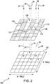
- Exemplary sensor array 102 illustrated as detached from mask 106, receives rays 14 and 16 from scene 12, filtered spatially according to the distribution of all-pass elements 108, and generates a spatially random patchwork image 18.
- the different qualities in the resulting images are geometrically randomly spaced, geometrically pseudo-randomly spaced, or geometrically spaced according to a particular distribution corresponding to the spatial irregularity of mask 106.
- Exemplary mask 106 is illustrated having a spatially pseudo-random plurality of all-pass elements 108, a plurality of first filter elements 110, a plurality of second filter elements 112, a plurality of third filter elements 114, and a fourth plurality of filter elements 116.
- Each all-pass element 108 passes all polarizations of light received at respective all-pass elements 108 to sensor array 102.
- Each first filter element 110 passes 0-degree polarization light received at mask 106 to sensor array 102.
- Each second filter element 112 passes 45-degree polarization light received at mask 106 to sensor array 102.
- Each third filter element 114 passes 90-degree polarization light received at mask 106 to sensor array 102.
- Each fourth filter element 116 passes 135-degree polarization light received at mask 106 to sensor array 102.
- Mask 106 is shown detached from sensor array 102 for illustration purposes; as will be appreciated mask 106 can be attached to sensor array 102.
- Light rays 22, 24, 26, and 28 from scene 12 are filtered by polarization filter elements 110, 112, 114, and 116 to produce filtered light rays 32, 34, 36, and 38 resulting in a patchwork image 18.
- Light ray 20 passes through all-pass element 108 resulting a light ray 30 containing all polarization of light.
- the different polarizations in the resulting images may be irregularly spaced or geometrically unordered, corresponding to the spatial irregularity of mask 106.
- filter elements 32, 34, 36, and 38 comprise bandpass or bandstop filters for different wavelengths, then the resulting images are a pseudo-random patchwork by wavelength. If filter elements 32, 34, 36, and 38 comprise different attenuations, then the resulting images are a pseudo-random patchwork by intensity, etc. It will be shown that these pseudo-random patchwork images may be reconstructed into, e.g., a high precision image, with higher accuracy than previously known.
- mask 106 may be associated with a sensor or camera 118 containing sensor array 102 and communicating with a processor or computer 120. Scene 12 to be captured is shown reconstructed and displayed at 122 on computer 120.
- the use of the pseudo-randomly ordered mask 106 with all-pass elements 108 provides benefits, as will be described below. Particularly when utilized in combination with modern reconstruction algorithms, more accurate images are provided.
- Communication between camera 118 and computer 120 may be a wired channel or alternatively may be any other optical, wireless, radio channel, or any other type of channel capable of transmitting images and videos between two points including links involving the World Wide Web (www) or the internet.
- the pseudo-random imaging reconstruction depends critically on a mathematical property called sparsity.
- Sparsity is a property whereby some data, e.g., an image, may be represented by only a few non-zero numbers (also called coefficients) which multiply an appropriate set of basis functions.
- Natural imagery is known to be sparse because these images can be compressed (using relatively few coefficients and Fourier or Wavelet basis functions) and accurately reconstructed from these few coefficients.
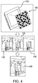
- three images 122, 124, and 126 may be reconstructed from three distinct pseudo-random images corresponding to three different polarization filters with shared (constraining) information corresponding to all-pass elements 108 (shown in Fig. 1 ).
- an image corresponding to the all-pass elements 128 may be reconstructed and may act as a constraint on the reconstruction of the three images 122, 124, and 126.
- the reconstruction of images 122, 124, and 126 is more accurate than would otherwise by the case due to the common constraint for each image imposed by the information shared by the three images.
- a mask 206 is shown.
- Mask 206 is similar to mask 106 and may be additionally a time-varying mask.
- mask 206 includes a first filter element 212 with a plurality of apertures 210, a second filter element 214 is a plurality of apertures 210, and a third filter element 216 with a plurality of apertures 210.
- Apertures 210 allow received electromagnetic radiation to pass unfiltered through a given filter element, and may traverse each filter element of mask 206 according to the registration of filter elements 212, 214, and 216.
- aligned apertures in each filter element form respective all-pass elements within mask 206.
- First filter element 212 filters received electromagnetic radiation according to a first quality at locations outside of apertures 210. Electromagnetic radiation received by first filter element 212 at apertures 210 is passed along imaging axis I and towards a sensor array as described above. This can include passing the electromagnetic radiation to second filter element 214, which is axially stacked below (relative to the received electromagnetic radiation) first filter element 212 along imaging axis I, according to the registration of first filter element 212 with second filter element 214.
- Second filter element 214 filters received electromagnetic radiation according to a second quality different from the first quality at locations outside of apertures 210. Electromagnetic radiation received by second filter element 214 at apertures 210 is passed along imaging axis I and towards the underlying sensor array. This can include passing the electromagnetic radiation to third filter element 216, which is axially stacked below (relative to the received electromagnetic radiation) second filter element 214 along imaging axis I, according to the registration of second filter element 214 with third filter element 216.
- Third filter element 216 filters received electromagnetic radiation according to a third quality, which is different from the first and second qualities, at locations outside of apertures 210. Electromagnetic radiation received by third filter element 216 at apertures 210 is passed along imaging axis I and towards the underlying sensor array.
- position of one filter element may be changed relative to the other filter elements.
- Position can be changed by rotating R the filter element about imaging axis I, as shown in Fig. 5B .
- Position can be changed by shifting S the filter element relative to the imaging axis I, as also shown in Fig. 5B .
- Changing the position of one of the filter elements relative to the other filter elements changes the location apertures 210 in relation to the other filter elements and apertures, improving accuracy in image reconstruction by changing over to the location of all-pass information in the images associated with each filter element.
- This disclosure creates a pseudo-randomly ordered mask having an array of all-pass and mask elements that selectively filter according polarization level where each pixel of a sensor (e.g., an imaging chip) is covered by one mask element.
- An image of a natural scene is captured through the mask.
- the pixels corresponding to a given polarization level are called a pseudo-random image.
- For each exposure then, there are several pseudo-random images each corresponding to the pixels of each level, e.g., a first level corresponding to a first polarization and a second level corresponding to a second polarization.
- computational methods are used to reconstruct the desired high dynamic range (HDR), high precision, and/or high accuracy image. While this exposition is primarily with respect to multi-polarization reconstruction, the invention applies equally to multispectral imaging, multi-intensity imaging, direction of arrival imaging, and other imaging where the incoming electromagnetic or acoustic waves may be separated by filters.
- N pseudo-random images for any scene corresponding to N polarizations, each pseudo-random image being related to the other pseudo random images by the information corresponding to the spatial locations of all-pass elements 108.
- N pseudo-random images For each exposure, then, there are N pseudo-random images each corresponding to the pixels of one polarization level where one of the levels is all polarizations.
- each pixel of an imaging chip comprising n-by-m pixels is covered by an n-by-m size mask where each pixel of the imaging chip is covered by exactly one mask location and, therefore, one polarization element or one all-pass element.
- multiple imaging chip pixels may be covered by one mask location, e.g., if the mask is of size n/2 by m/2.
- the mask and imaging chip pixels need not be exactly aligned nor adjacent to each other.
- the method of generating a pseudo-random mask may vary.
- different transparency levels, colors, polarizations, etc. are assigned independently at each mask location and uniformly throughout the mask.
- mask levels can be correlated and uniformly distributed on average.
- the magnitude of the spatial variation of mask levels in a subset of adjacent locations is the key parameter of a distribution that may control the statistical properties of the mask. This exemplary distribution depends on the number of mask locations in the subset and on a correlation function. Specifically, in the former case of the independently distributed mask levels, the squared magnitude of spatial variation may be directly proportional to the number of mask levels in the subset. In the latter case of correlated distributions this dependence can be modified.
- a reconstruction algorithm is then used.
- One embodiment may use a well-known low-rank matrix completion algorithm.
- Another is to apply a dictionary learning algorithm for image inpainting.
- the different qualities of scenes can be reconstructed independently (called independent reconstruction) or, preferably, by joint optimization (called joint reconstruction).
- the independent reconstruction approach reconstructs each quality of the scene independently, using only responses of the pixels corresponding to one mask level.
- the joint reconstruction approach reconstructs all qualities of the scene at once, implicitly or explicitly assuming that the structure of the scene qualities are related and using the responses of pixels corresponding to a plurality of mask levels.
- Independent reconstruction algorithms are well known in the art.
- the novel joint reconstruction can provide better reconstruction accuracy than independent reconstruction, particularly by adding constraints based on the all-pass elements.
- An imaging method employing mask 106 includes receiving electromagnetic radiation, e.g., light, with a plurality of qualities from a scene to be captured at a mask, e.g., mask 106 (shown in Fig. 1 ). A first portion of the received electromagnetic radiation is passed without filtering through the mask. A second portion of the received electromagnetic radiation is passed through the mask having one or more qualities removed from the light.
- the all-pass elements are spatially distributed among the plurality of filter elements such that a pseudo-random image is acquired. An image is thereafter reconstructed jointly with the all-pass data as a constraint on the reconstruction, e.g., the sum of separate polarization images must equal the all-pass image.
- the methods and systems of the present disclosure provide for imaging methods, imaging systems, and masks for imaging systems with superior properties including improved accuracy reconstruction of images, e.g., high-dynamic range images, multi-polarization images, and/or multi-spectral images, from filtered images. While the apparatus and methods of the subject disclosure have been shown and described with reference to preferred embodiments, those skilled in the art will readily appreciate that changes and/or modifications may be made thereto without departing from the scope of the subject disclosure.
Landscapes
- Physics & Mathematics (AREA)
- General Physics & Mathematics (AREA)
- Optics & Photonics (AREA)
- Engineering & Computer Science (AREA)
- Multimedia (AREA)
- Signal Processing (AREA)
- Spectroscopy & Molecular Physics (AREA)
- Studio Devices (AREA)
- Image Processing (AREA)
- Apparatus For Radiation Diagnosis (AREA)
- Investigating, Analyzing Materials By Fluorescence Or Luminescence (AREA)
Abstract
Description
- The present disclosure relates to imaging systems and methods, and more particularly to collecting high resolution image data for one or more qualities of light with masked sensor arrangements. The qualities of light include intensity, wavelength, and polarization.
- Image reconstruction is commonly used in numerous technical areas to acquire information regarding objects of interest within a background environment. As an example, surveillance aircraft commonly capture image data at multiple wavelengths, which must be reconstructed to provide information. This image data is generally captured quickly, and the accuracy, spatial resolution, and dynamic range must be as high as possible.
- Image data is generally acquired using a sensor array, e.g., a camera, which may be provided with a filter. The filter typically breaks the incoming light into different levels. For example, some sensor arrays break incoming light into different intensity levels, although different spectral levels (i.e. the colors red, blue, green, for instance) may be separated by the filter. It is also known to use different filters to separate other qualities within the light, such as polarization, the result of which is that information peculiar to a given level of the quality of light and conveyed independently of other levels reaches the sensor, and is thereby selectively captured in the image data. Such filters, e.g., a Bayer filter, are generally provided in regular pattern for light in the human-visible portion of the visible spectrum.
- Such conventional methods and systems have generally been considered satisfactory for their intended purpose. However, there is still a need in the art for improved filters, image sensors employing such filters, and methods of reconstructing images using image data collected by such image sensors. The present disclosure provides a solution for this need.
- An imaging method includes receiving electromagnetic radiation with a plurality of qualities from a scene to be captured at a mask and passing a first portion of the received electromagnetic radiation having the plurality of qualities present in the received electromagnetic radiation through the mask. One or more qualities of the received electromagnetic radiation are removed from a second portion of the received electromagnetic radiation, and the second portion of the received electromagnetic radiation absent the one or more removed qualities is passed through the mask.
- In certain embodiments, the method can include receiving the first portion of the electromagnetic radiation and the second portion of the electromagnetic radiation at a sensor array optically coupled to the mask. The method can include simultaneously passing the first portion of the electromagnetic radiation and the second portion of the electromagnetic radiation through the mask. The first portion of the electromagnetic radiation and the second portion of the electromagnetic radiation can be received at spatially separate portions of a sensor array optically coupled to the mask.
- It is also contemplated that, in accordance with certain embodiments, removing the one or more qualities can include filtering the received electromagnetic radiation according to a polarization quality. The first portion can include all polarization qualities of the received electromagnetic radiation. Removing the one or more qualities can include filtering the received electromagnetic radiation according to an intensity quality. The first portion can include all intensity qualities of the received electromagnetic radiation. Removing the one or more qualities can include filtering the received electromagnetic radiation according to a spectral quality. The first portion can include all spectral qualities of the received electromagnetic radiation.
- In accordance with certain embodiments, the method can include removing from a third portion of the electromagnetic radiation one or more of the plurality of qualities of the electromagnetic radiation using the mask. The third portion of the electromagnetic radiation can be passed through the mask. An image can be reconstructed using the second portion of the electromagnetic radiation and the third portion of the electromagnetic radiation based on the first portion of the electromagnetic radiation.
- An imaging system includes a sensor array with a plurality of pixels and a mask optically coupled to the sensor array. The mask includes a plurality of first mask elements and a plurality of second mask elements, the plurality of first mask elements are spatially distributed among the plurality of second mask elements. The second mask elements remove one or more qualities of electromagnetic radiation received at respective second mask elements. The first mask elements pass all qualities of electromagnetic radiation received at respective first mask elements.
- In embodiments, the second mask elements can remove one or more polarization quality, spectral quality, or intensity quality from received electromagnetic radiation. The mask can include equivalent numbers of first mask elements and the second mask elements, more first mask elements than second mask elements, or fewer first mask elements than second mask elements. The mask can include a plurality of third mask elements, each third mask element removing a quality from received electromagnetic different than that removed from each of the plurality of second mask elements and passed by each of the plurality of first mask elements.
- A mask for an imaging system includes a plurality of first mask elements and a plurality of second mask elements distributed among the first mask elements. Each first mask element passes all qualities of electromagnetic radiation received at a respective first mask element. Each second mask element removes one or more polarization quality from electromagnetic radiation received at a respective second mask element.
- These and other features of the systems and methods of the subject disclosure will become more readily apparent to those skilled in the art from the following detailed description of the preferred embodiments taken in conjunction with the drawings.
- So that those skilled in the art to which the subject disclosure appertains will readily understand how to make and use the devices and methods of the subject disclosure without undue experimentation, embodiments thereof will be described in detail herein below with reference to certain figures, wherein:
-
Fig. 1 is a schematic view of an exemplary embodiment of an imaging system constructed in accordance with the present disclosure, showing a mask with all-pass element optically coupled to a sensor array; -
Fig. 2 is a schematic view of the imaging system ofFig. 1 , schematically showing the imaging system capturing difference qualities of electromagnetic radiation for reconstructing an image of a scene to be captured; -
Fig. 3 is schematic view of an image reconstruction step, showing images being reconstructed using differently filtered portions of light and shared information at selected image locations; -
Fig. 4 is schematic view of an imaging method, showing distinct images corresponding to a group of all-pass elements, a group of filter elements filtering according to a first polarization, a second group of filter elements filtering according to a second polarization and a third group of filter elements filtering according to a third polarization; and -
Figs. 5A and 5B are schematic views of second embodiment of a mask, showing a time-varying mask. - Reference will now be made to the drawings wherein like reference numerals identify similar structural features or aspects of the subject disclosure. For purposes of explanation and illustration, and not limitation, a partial view of an exemplary embodiment of an imaging system in accordance with the disclosure is shown in
Fig. 1 and is designated generally byreference character 100. Other embodiments of imaging systems, image reconstruction methods, and masks for imaging systems in accordance with the disclosure, or aspects thereof, are provided inFigs. 2 - 5 , as will be described. The systems and methods described herein can be used for reconstructing high dynamic range, high precision, or high resolution images using joint reconstruction constrained by a spatially distributed all-polarization, full-intensity or wide-spectra image data, however the present disclosure is not limited to polarization, intensity, or spectral joint reconstruction imaging systems or methods in general. - As shown in
Fig. 1 ,imaging system 100 includes asensor array 102 with a plurality ofpixels 104 and amask 106.Mask 106 is optically coupled tosensor array 102 and includes a plurality of all-pass elements 108 and a plurality offilter elements 110. The plurality of all-pass elements 108 are interspersed among the plurality offilter elements 110. Each of the plurality of all-pass elements 108 are configured and adapted to pass all qualities ofelectromagnetic radiation 10 from a scene to be imaged 12 received at the respective all-pass element tosensor array 102. Each of the plurality of filter elements are configured and adapted to filter one or more quality ofelectromagnetic radiation 10 from the scene to be imaged 12. As used herein qualities of electromagnetic radiation can include, without limitation, polarization qualities, intensity qualities, and /or spectral qualities. -
Mask 106 receives electromagnetic radiation and separates the received electromagnetic radiation based upon the spatial distribution of all-pass elements 108 amongfilter elements 110. Separation may be on the basis of qualities of light, and may include polarization, intensity level, spectral level (e.g., the colors red, blue, green, for instance), or other qualities within the light.Exemplary sensor array 102, illustrated as detached frommask 106, receivesrays scene 12, filtered spatially according to the distribution of all-pass elements 108, and generates a spatiallyrandom patchwork image 18. As can be appreciated, the different qualities in the resulting images are geometrically randomly spaced, geometrically pseudo-randomly spaced, or geometrically spaced according to a particular distribution corresponding to the spatial irregularity ofmask 106. - Referring to
Fig. 2 details ofimaging system 100 are shown.Exemplary mask 106 is illustrated having a spatially pseudo-random plurality of all-pass elements 108, a plurality offirst filter elements 110, a plurality ofsecond filter elements 112, a plurality of third filter elements 114, and a fourth plurality offilter elements 116. Each all-pass element 108 passes all polarizations of light received at respective all-pass elements 108 tosensor array 102. Eachfirst filter element 110 passes 0-degree polarization light received atmask 106 tosensor array 102. Eachsecond filter element 112 passes 45-degree polarization light received atmask 106 tosensor array 102. Each third filter element 114 passes 90-degree polarization light received atmask 106 tosensor array 102. Eachfourth filter element 116 passes 135-degree polarization light received atmask 106 tosensor array 102.Mask 106 is shown detached fromsensor array 102 for illustration purposes; as will be appreciatedmask 106 can be attached tosensor array 102. Light rays 22, 24, 26, and 28 fromscene 12 are filtered bypolarization filter elements patchwork image 18.Light ray 20 passes through all-pass element 108 resulting alight ray 30 containing all polarization of light. As can be appreciated, the different polarizations in the resulting images may be irregularly spaced or geometrically unordered, corresponding to the spatial irregularity ofmask 106. Iffilter elements filter elements - As shown in
Fig. 3 ,mask 106 may be associated with a sensor orcamera 118 containingsensor array 102 and communicating with a processor orcomputer 120.Scene 12 to be captured is shown reconstructed and displayed at 122 oncomputer 120. The use of the pseudo-randomly orderedmask 106 with all-pass elements 108 provides benefits, as will be described below. Particularly when utilized in combination with modern reconstruction algorithms, more accurate images are provided. Communication betweencamera 118 andcomputer 120 may be a wired channel or alternatively may be any other optical, wireless, radio channel, or any other type of channel capable of transmitting images and videos between two points including links involving the World Wide Web (www) or the internet. - The pseudo-random imaging reconstruction depends critically on a mathematical property called sparsity. Sparsity is a property whereby some data, e.g., an image, may be represented by only a few non-zero numbers (also called coefficients) which multiply an appropriate set of basis functions. Natural imagery is known to be sparse because these images can be compressed (using relatively few coefficients and Fourier or Wavelet basis functions) and accurately reconstructed from these few coefficients.
- As shown in
Fig. 4 , threeimages Fig. 1 ). Conceptually, an image corresponding to the all-pass elements 128 may be reconstructed and may act as a constraint on the reconstruction of the threeimages images - Referring to
Figs. 5A and 5B , amask 206 is shown.Mask 206 is similar to mask 106 and may be additionally a time-varying mask. In thisrespect mask 206 includes afirst filter element 212 with a plurality ofapertures 210, asecond filter element 214 is a plurality ofapertures 210, and athird filter element 216 with a plurality ofapertures 210.Apertures 210 allow received electromagnetic radiation to pass unfiltered through a given filter element, and may traverse each filter element ofmask 206 according to the registration offilter elements mask 206. -
First filter element 212 filters received electromagnetic radiation according to a first quality at locations outside ofapertures 210. Electromagnetic radiation received byfirst filter element 212 atapertures 210 is passed along imaging axis I and towards a sensor array as described above. This can include passing the electromagnetic radiation tosecond filter element 214, which is axially stacked below (relative to the received electromagnetic radiation)first filter element 212 along imaging axis I, according to the registration offirst filter element 212 withsecond filter element 214. -
Second filter element 214 filters received electromagnetic radiation according to a second quality different from the first quality at locations outside ofapertures 210. Electromagnetic radiation received bysecond filter element 214 atapertures 210 is passed along imaging axis I and towards the underlying sensor array. This can include passing the electromagnetic radiation tothird filter element 216, which is axially stacked below (relative to the received electromagnetic radiation)second filter element 214 along imaging axis I, according to the registration ofsecond filter element 214 withthird filter element 216. -
Third filter element 216 filters received electromagnetic radiation according to a third quality, which is different from the first and second qualities, at locations outside ofapertures 210. Electromagnetic radiation received bythird filter element 216 atapertures 210 is passed along imaging axis I and towards the underlying sensor array. - As electromagnetic radiation is received by
mask 206, position of one filter element may be changed relative to the other filter elements. Position can be changed by rotating R the filter element about imaging axis I, as shown inFig. 5B . Position can be changed by shifting S the filter element relative to the imaging axis I, as also shown inFig. 5B . Changing the position of one of the filter elements relative to the other filter elements changes thelocation apertures 210 in relation to the other filter elements and apertures, improving accuracy in image reconstruction by changing over to the location of all-pass information in the images associated with each filter element. - This disclosure creates a pseudo-randomly ordered mask having an array of all-pass and mask elements that selectively filter according polarization level where each pixel of a sensor (e.g., an imaging chip) is covered by one mask element. An image of a natural scene is captured through the mask. The pixels corresponding to a given polarization level are called a pseudo-random image. For each exposure, then, there are several pseudo-random images each corresponding to the pixels of each level, e.g., a first level corresponding to a first polarization and a second level corresponding to a second polarization. From the acquired pseudo-random images, computational methods are used to reconstruct the desired high dynamic range (HDR), high precision, and/or high accuracy image. While this exposition is primarily with respect to multi-polarization reconstruction, the invention applies equally to multispectral imaging, multi-intensity imaging, direction of arrival imaging, and other imaging where the incoming electromagnetic or acoustic waves may be separated by filters.
- For polarization imaging, a mask of N discrete different polarization levels is created. There are, therefore, N pseudo-random images for any scene corresponding to N polarizations, each pseudo-random image being related to the other pseudo random images by the information corresponding to the spatial locations of all-
pass elements 108. For each exposure, then, there are N pseudo-random images each corresponding to the pixels of one polarization level where one of the levels is all polarizations. For each pseudo-random image (corresponding to each polarization level), there are a limited number of observed pixels (1/N), from which to reconstruct the whole image. - In the exemplary embodiment each pixel of an imaging chip comprising n-by-m pixels is covered by an n-by-m size mask where each pixel of the imaging chip is covered by exactly one mask location and, therefore, one polarization element or one all-pass element. In an alternative embodiment, multiple imaging chip pixels may be covered by one mask location, e.g., if the mask is of size n/2 by m/2. In yet another embodiment, the mask and imaging chip pixels need not be exactly aligned nor adjacent to each other.
- The method of generating a pseudo-random mask may vary. In one example, different transparency levels, colors, polarizations, etc. are assigned independently at each mask location and uniformly throughout the mask. In more general case, mask levels can be correlated and uniformly distributed on average. The magnitude of the spatial variation of mask levels in a subset of adjacent locations is the key parameter of a distribution that may control the statistical properties of the mask. This exemplary distribution depends on the number of mask locations in the subset and on a correlation function. Specifically, in the former case of the independently distributed mask levels, the squared magnitude of spatial variation may be directly proportional to the number of mask levels in the subset. In the latter case of correlated distributions this dependence can be modified.
- A reconstruction algorithm is then used. One embodiment may use a well-known low-rank matrix completion algorithm. Another is to apply a dictionary learning algorithm for image inpainting. The different qualities of scenes can be reconstructed independently (called independent reconstruction) or, preferably, by joint optimization (called joint reconstruction). The independent reconstruction approach reconstructs each quality of the scene independently, using only responses of the pixels corresponding to one mask level. The joint reconstruction approach reconstructs all qualities of the scene at once, implicitly or explicitly assuming that the structure of the scene qualities are related and using the responses of pixels corresponding to a plurality of mask levels. Independent reconstruction algorithms are well known in the art. The novel joint reconstruction can provide better reconstruction accuracy than independent reconstruction, particularly by adding constraints based on the all-pass elements.
- An imaging
method employing mask 106 includes receiving electromagnetic radiation, e.g., light, with a plurality of qualities from a scene to be captured at a mask, e.g., mask 106 (shown inFig. 1 ). A first portion of the received electromagnetic radiation is passed without filtering through the mask. A second portion of the received electromagnetic radiation is passed through the mask having one or more qualities removed from the light. The all-pass elements are spatially distributed among the plurality of filter elements such that a pseudo-random image is acquired. An image is thereafter reconstructed jointly with the all-pass data as a constraint on the reconstruction, e.g., the sum of separate polarization images must equal the all-pass image. - The methods and systems of the present disclosure, as described above and shown in the drawings, provide for imaging methods, imaging systems, and masks for imaging systems with superior properties including improved accuracy reconstruction of images, e.g., high-dynamic range images, multi-polarization images, and/or multi-spectral images, from filtered images. While the apparatus and methods of the subject disclosure have been shown and described with reference to preferred embodiments, those skilled in the art will readily appreciate that changes and/or modifications may be made thereto without departing from the scope of the subject disclosure.
Claims (15)
- An imaging method, comprising:receiving electromagnetic radiation with a plurality of qualities from a scene to be captured;passing a first portion of the electromagnetic radiation having the plurality of qualities through a mask; andremoving one or more of the plurality of qualities from a second portion of the electromagnetic radiation by passing the second portion of the electromagnetic radiation through the mask.
- An imaging method as recited in claim 1, further comprising receiving the first portion of the electromagnetic radiation and the second portion of the electromagnetic radiation at a sensor array optically coupled to the mask.
- An imaging method as recited in any preceding claim, further comprising simultaneously passing the first portion of the electromagnetic radiation and the second portion of the electromagnetic radiation through the mask.
- An imaging method as recited in any preceding claim, further comprising receiving the first portion of the electromagnetic radiation and the second portion of the electromagnetic radiation at spatially separate portions of a sensor array optically coupled to the mask.
- An imaging method as recited in any preceding claim, wherein removing the one or more quality from the second portion of the electromagnetic radiation includes filtering the received electromagnetic radiation according to a polarization quality;
optionally wherein the first portion of the electromagnetic radiation passed through the mask includes all polarization qualities of the received electromagnetic radiation. - An imaging method as recited in any preceding claim, wherein removing the one or more quality from the second portion of the electromagnetic radiation includes filtering the received electromagnetic radiation according to an intensity quality;
optionally wherein the first portion of the electromagnetic radiation passed through the mask includes all intensity qualities of the received electromagnetic radiation. - An imaging method as recited in any preceding claim, wherein removing the one or more quality from the second portion of the electromagnetic radiation includes filtering the received electromagnetic radiation according to a spectral quality;
optionally wherein the first portion of the electromagnetic radiation passed through the mask includes all spectral qualities of the received electromagnetic radiation. - A method as recited in any preceding claim, further comprising:removing from a third portion of the electromagnetic radiation one or more of the plurality of qualities of the electromagnetic radiation by passing the third portion of the electromagnetic radiation through the mask; andreconstructing an image using the second portion of the electromagnetic radiation and the third portion of the electromagnetic radiation based on the first portion of the electromagnetic radiation.
- A method as recited in any preceding claim, further comprising shifting the mask relative to the received electromagnetic radiation;
or further comprising rotating the mask relative to the received electromagnetic radiation. - An imaging system, comprising:a sensor array with a plurality of pixels; anda mask optically coupled to the sensor array, wherein the mask comprises a plurality of first mask elements and a plurality of second mask elements,wherein the plurality of first mask elements are spatially distributed among the plurality of second mask elements,wherein the plurality of second mask elements remove one or more qualities of electromagnetic radiation received at respective second mask elements,wherein the plurality of first mask elements pass all qualities of electromagnetic radiation received at respective first mask elements.
- An imaging system as recited in claim 10, wherein the second mask elements filter according a quality of light selected from polarization, spectral, and intensity.
- An imaging system as recited in claim 10 or claim 11, wherein the mask includes a plurality of third mask elements, each of the third mask elements removing a quality from received electromagnetic different than that removed from each of the plurality of second mask elements and passed by each of the plurality of first mask elements.
- A mask for an imaging system, comprising:a plurality of all-pass elements, each all-pass element passing all qualities of electromagnetic radiation received at the respective all-pass element; anda plurality of filter elements distributed among the plurality of all-pass elements, each filter element removing one or more quality from electromagnetic radiation received at the respective filter element;optionally wherein the mask comprises (a) equivalent numbers of first mask elements and the second mask elements, (b) a greater number of first mask elements than second mask elements, or (c) a smaller number of first mask elements than second mask elements.
- A mask as recited in claim 13, wherein each of the plurality of all-pass elements is fixed relative to each of the plurality of the filter elements.
- A mask as recited in claim 13 or claim 14, wherein the plurality of filter elements comprises a first filter element and second filter element, the second filter element underlying the first filter element, and one or more of the plurality of all-pass elements comprising an aperture defined by the first filter element in registration with an aperture defined by the second filter element.
Applications Claiming Priority (1)
| Application Number | Priority Date | Filing Date | Title |
|---|---|---|---|
| US15/175,877 US10048413B2 (en) | 2016-06-07 | 2016-06-07 | Imaging systems and methods |
Publications (3)
| Publication Number | Publication Date |
|---|---|
| EP3255886A2 true EP3255886A2 (en) | 2017-12-13 |
| EP3255886A3 EP3255886A3 (en) | 2018-02-28 |
| EP3255886B1 EP3255886B1 (en) | 2020-09-02 |
Family
ID=59239764
Family Applications (1)
| Application Number | Title | Priority Date | Filing Date |
|---|---|---|---|
| EP17174676.1A Active EP3255886B1 (en) | 2016-06-07 | 2017-06-07 | Imaging systems and methods |
Country Status (2)
| Country | Link |
|---|---|
| US (1) | US10048413B2 (en) |
| EP (1) | EP3255886B1 (en) |
Cited By (1)
| Publication number | Priority date | Publication date | Assignee | Title |
|---|---|---|---|---|
| CN113557709A (en) * | 2019-04-19 | 2021-10-26 | 索尼集团公司 | Imaging apparatus, image processing apparatus, and image processing method |
Families Citing this family (10)
| Publication number | Priority date | Publication date | Assignee | Title |
|---|---|---|---|---|
| US11056518B2 (en) * | 2016-08-18 | 2021-07-06 | Sony Corporation | Imaging apparatus and imaging method |
| JP2020067625A (en) * | 2018-10-26 | 2020-04-30 | 国立大学法人九州工業大学 | Optical device |
| JP7333943B2 (en) * | 2019-06-26 | 2023-08-28 | 国立研究開発法人産業技術総合研究所 | Polarizing element having wire grid structure and manufacturing method thereof |
| CN111292264B (en) * | 2020-01-21 | 2023-04-21 | 武汉大学 | Image high dynamic range reconstruction method based on deep learning |
| WO2022080121A1 (en) * | 2020-10-16 | 2022-04-21 | ソニーグループ株式会社 | Polarized light imaging device, binary mask, image processing system, and image processing method |
| WO2022239326A1 (en) * | 2021-05-12 | 2022-11-17 | ソニーグループ株式会社 | Imaging device, and method for operating imaging device |
| US11256987B1 (en) * | 2021-06-02 | 2022-02-22 | SambaNova Systems, Inc. | Memory efficient dropout, with reordering of dropout mask elements |
| US11328209B1 (en) | 2021-06-02 | 2022-05-10 | SambaNova Systems, Inc. | Dual cycle tensor dropout in a neural network |
| US12289507B2 (en) | 2021-11-08 | 2025-04-29 | Sensors Unlimited, Inc. | Neuromorphic compressive sensing in low-light environment |
| CN115346074B (en) * | 2022-09-02 | 2023-06-16 | 北京百度网讯科技有限公司 | Training method, image processing device, electronic equipment and storage medium |
Family Cites Families (14)
| Publication number | Priority date | Publication date | Assignee | Title |
|---|---|---|---|---|
| US5548333A (en) * | 1993-12-10 | 1996-08-20 | Nikon Corporation | Color mixing prevention and color balance setting device and method for a field-sequential color television camera |
| JP2002290843A (en) | 2001-03-26 | 2002-10-04 | Olympus Optical Co Ltd | Image input device |
| FR2917559B1 (en) | 2007-06-12 | 2009-12-25 | Centre Nat Rech Scient | DIGITAL IMAGE SENSOR, METHOD FOR ACQUIRING AND RECONSTRUCTING IMAGES, AND SYSTEM FOR IMPLEMENTING SAME |
| JP5428509B2 (en) | 2009-05-11 | 2014-02-26 | ソニー株式会社 | Two-dimensional solid-state imaging device and polarized light data processing method in two-dimensional solid-state imaging device |
| US8345144B1 (en) * | 2009-07-15 | 2013-01-01 | Adobe Systems Incorporated | Methods and apparatus for rich image capture with focused plenoptic cameras |
| US20110109773A1 (en) | 2009-11-10 | 2011-05-12 | General Electric Company | System and method for adaptive nonlinear compressed visual sensing |
| EP2502423A2 (en) * | 2009-11-20 | 2012-09-26 | Mritunjay Singh | Method and system for compressive color image sampling and reconstruction |
| US20130070138A1 (en) | 2010-02-22 | 2013-03-21 | Richard G Baraniuk | Number Of Pixels In Detector Arrays Using Compressive Sensing |
| WO2013114888A1 (en) | 2012-02-02 | 2013-08-08 | パナソニック株式会社 | Imaging device |
| US9110240B2 (en) * | 2013-03-05 | 2015-08-18 | Rambus Inc. | Phase gratings with odd symmetry for high-resolution lensed and lensless optical sensing |
| US9488444B2 (en) * | 2013-04-29 | 2016-11-08 | Raytheon Company | Time-multiplexed broadband and multi-filtered electro-optic sensor |
| US8917327B1 (en) | 2013-10-04 | 2014-12-23 | icClarity, Inc. | Method to use array sensors to measure multiple types of data at full resolution of the sensor |
| US9300865B2 (en) | 2014-01-24 | 2016-03-29 | Goodrich Corporation | Random imaging |
| US9467628B2 (en) * | 2014-08-26 | 2016-10-11 | Sensors Unlimited, Inc. | High dynamic range image sensor |
-
2016
- 2016-06-07 US US15/175,877 patent/US10048413B2/en active Active
-
2017
- 2017-06-07 EP EP17174676.1A patent/EP3255886B1/en active Active
Non-Patent Citations (1)
| Title |
|---|
| None |
Cited By (4)
| Publication number | Priority date | Publication date | Assignee | Title |
|---|---|---|---|---|
| CN113557709A (en) * | 2019-04-19 | 2021-10-26 | 索尼集团公司 | Imaging apparatus, image processing apparatus, and image processing method |
| EP3937476A4 (en) * | 2019-04-19 | 2022-05-04 | Sony Group Corporation | Image capturing device, image processing device, and image processing method |
| US11997398B2 (en) | 2019-04-19 | 2024-05-28 | Sony Group Corporation | Imaging apparatus, image processing apparatus, and image processing method |
| CN113557709B (en) * | 2019-04-19 | 2024-08-02 | 索尼集团公司 | Imaging apparatus, image processing apparatus, and image processing method |
Also Published As
| Publication number | Publication date |
|---|---|
| US10048413B2 (en) | 2018-08-14 |
| EP3255886A3 (en) | 2018-02-28 |
| EP3255886B1 (en) | 2020-09-02 |
| US20170351012A1 (en) | 2017-12-07 |
Similar Documents
| Publication | Publication Date | Title |
|---|---|---|
| EP3255886B1 (en) | Imaging systems and methods | |
| US10274420B2 (en) | Compact multifunctional system for imaging spectroscopy | |
| EP2715447B1 (en) | System and method for extending depth of field in a lens system by use of color-dependent wavefront coding | |
| US8027041B1 (en) | Compact snapshot multispectral imaging system | |
| US9300865B2 (en) | Random imaging | |
| US8203114B2 (en) | Adaptive spatial-spectral processing (ASSP) | |
| US9811051B2 (en) | Apparatus and method for performing in-line lens-free digital holography of an object | |
| US9426401B2 (en) | Mechanisms for obtaining information from a scene | |
| JP6297234B1 (en) | Compound eye imaging apparatus, image processing method, program, and recording medium | |
| US20210084219A1 (en) | Image-capturing apparatus, image-capturing method, and image-capturing device | |
| US20180182069A1 (en) | Dual-sensor hyperspectral motion imaging system | |
| RU2595759C2 (en) | Method and image capturing device and simultaneous extraction of depth | |
| CN115152205A (en) | Camera device and method | |
| US20180286906A1 (en) | Image generation device and imaging device | |
| US11092489B2 (en) | Wide-angle computational imaging spectroscopy method and apparatus | |
| EP3232473B1 (en) | Masked pixel arrays | |
| Rueda et al. | Compressive spectral imaging based on colored coded apertures | |
| US12532085B2 (en) | Computational high-speed hyperspectral infrared camera system | |
| US9699394B2 (en) | Filter arrangement for image sensor | |
| Arja et al. | Seeing like a cephalopod: Colour vision with a monochrome event camera | |
| Picone et al. | Analysis of masks for compressed acquisitions in variational-based pansharpening | |
| HK1192328B (en) | System and method for extending depth of field in a lens system by use of color-dependent wavefront coding |
Legal Events
| Date | Code | Title | Description |
|---|---|---|---|
| PUAI | Public reference made under article 153(3) epc to a published international application that has entered the european phase |
Free format text: ORIGINAL CODE: 0009012 |
|
| STAA | Information on the status of an ep patent application or granted ep patent |
Free format text: STATUS: THE APPLICATION HAS BEEN PUBLISHED |
|
| AK | Designated contracting states |
Kind code of ref document: A2 Designated state(s): AL AT BE BG CH CY CZ DE DK EE ES FI FR GB GR HR HU IE IS IT LI LT LU LV MC MK MT NL NO PL PT RO RS SE SI SK SM TR |
|
| AX | Request for extension of the european patent |
Extension state: BA ME |
|
| PUAL | Search report despatched |
Free format text: ORIGINAL CODE: 0009013 |
|
| AK | Designated contracting states |
Kind code of ref document: A3 Designated state(s): AL AT BE BG CH CY CZ DE DK EE ES FI FR GB GR HR HU IE IS IT LI LT LU LV MC MK MT NL NO PL PT RO RS SE SI SK SM TR |
|
| AX | Request for extension of the european patent |
Extension state: BA ME |
|
| RIC1 | Information provided on ipc code assigned before grant |
Ipc: H04N 9/04 20060101AFI20180123BHEP |
|
| STAA | Information on the status of an ep patent application or granted ep patent |
Free format text: STATUS: REQUEST FOR EXAMINATION WAS MADE |
|
| STAA | Information on the status of an ep patent application or granted ep patent |
Free format text: STATUS: EXAMINATION IS IN PROGRESS |
|
| 17P | Request for examination filed |
Effective date: 20180823 |
|
| RBV | Designated contracting states (corrected) |
Designated state(s): AL AT BE BG CH CY CZ DE DK EE ES FI FR GB GR HR HU IE IS IT LI LT LU LV MC MK MT NL NO PL PT RO RS SE SI SK SM TR |
|
| 17Q | First examination report despatched |
Effective date: 20180918 |
|
| GRAP | Despatch of communication of intention to grant a patent |
Free format text: ORIGINAL CODE: EPIDOSNIGR1 |
|
| STAA | Information on the status of an ep patent application or granted ep patent |
Free format text: STATUS: GRANT OF PATENT IS INTENDED |
|
| INTG | Intention to grant announced |
Effective date: 20200312 |
|
| GRAS | Grant fee paid |
Free format text: ORIGINAL CODE: EPIDOSNIGR3 |
|
| GRAA | (expected) grant |
Free format text: ORIGINAL CODE: 0009210 |
|
| STAA | Information on the status of an ep patent application or granted ep patent |
Free format text: STATUS: THE PATENT HAS BEEN GRANTED |
|
| AK | Designated contracting states |
Kind code of ref document: B1 Designated state(s): AL AT BE BG CH CY CZ DE DK EE ES FI FR GB GR HR HU IE IS IT LI LT LU LV MC MK MT NL NO PL PT RO RS SE SI SK SM TR |
|
| REG | Reference to a national code |
Ref country code: GB Ref legal event code: FG4D |
|
| REG | Reference to a national code |
Ref country code: AT Ref legal event code: REF Ref document number: 1310180 Country of ref document: AT Kind code of ref document: T Effective date: 20200915 Ref country code: CH Ref legal event code: EP |
|
| REG | Reference to a national code |
Ref country code: DE Ref legal event code: R096 Ref document number: 602017022630 Country of ref document: DE |
|
| REG | Reference to a national code |
Ref country code: IE Ref legal event code: FG4D |
|
| REG | Reference to a national code |
Ref country code: LT Ref legal event code: MG4D |
|
| PG25 | Lapsed in a contracting state [announced via postgrant information from national office to epo] |
Ref country code: HR Free format text: LAPSE BECAUSE OF FAILURE TO SUBMIT A TRANSLATION OF THE DESCRIPTION OR TO PAY THE FEE WITHIN THE PRESCRIBED TIME-LIMIT Effective date: 20200902 Ref country code: SE Free format text: LAPSE BECAUSE OF FAILURE TO SUBMIT A TRANSLATION OF THE DESCRIPTION OR TO PAY THE FEE WITHIN THE PRESCRIBED TIME-LIMIT Effective date: 20200902 Ref country code: GR Free format text: LAPSE BECAUSE OF FAILURE TO SUBMIT A TRANSLATION OF THE DESCRIPTION OR TO PAY THE FEE WITHIN THE PRESCRIBED TIME-LIMIT Effective date: 20201203 Ref country code: FI Free format text: LAPSE BECAUSE OF FAILURE TO SUBMIT A TRANSLATION OF THE DESCRIPTION OR TO PAY THE FEE WITHIN THE PRESCRIBED TIME-LIMIT Effective date: 20200902 Ref country code: NO Free format text: LAPSE BECAUSE OF FAILURE TO SUBMIT A TRANSLATION OF THE DESCRIPTION OR TO PAY THE FEE WITHIN THE PRESCRIBED TIME-LIMIT Effective date: 20201202 Ref country code: BG Free format text: LAPSE BECAUSE OF FAILURE TO SUBMIT A TRANSLATION OF THE DESCRIPTION OR TO PAY THE FEE WITHIN THE PRESCRIBED TIME-LIMIT Effective date: 20201202 Ref country code: LT Free format text: LAPSE BECAUSE OF FAILURE TO SUBMIT A TRANSLATION OF THE DESCRIPTION OR TO PAY THE FEE WITHIN THE PRESCRIBED TIME-LIMIT Effective date: 20200902 |
|
| REG | Reference to a national code |
Ref country code: NL Ref legal event code: MP Effective date: 20200902 |
|
| REG | Reference to a national code |
Ref country code: AT Ref legal event code: MK05 Ref document number: 1310180 Country of ref document: AT Kind code of ref document: T Effective date: 20200902 |
|
| PG25 | Lapsed in a contracting state [announced via postgrant information from national office to epo] |
Ref country code: LV Free format text: LAPSE BECAUSE OF FAILURE TO SUBMIT A TRANSLATION OF THE DESCRIPTION OR TO PAY THE FEE WITHIN THE PRESCRIBED TIME-LIMIT Effective date: 20200902 Ref country code: PL Free format text: LAPSE BECAUSE OF FAILURE TO SUBMIT A TRANSLATION OF THE DESCRIPTION OR TO PAY THE FEE WITHIN THE PRESCRIBED TIME-LIMIT Effective date: 20200902 Ref country code: RS Free format text: LAPSE BECAUSE OF FAILURE TO SUBMIT A TRANSLATION OF THE DESCRIPTION OR TO PAY THE FEE WITHIN THE PRESCRIBED TIME-LIMIT Effective date: 20200902 |
|
| PG25 | Lapsed in a contracting state [announced via postgrant information from national office to epo] |
Ref country code: CZ Free format text: LAPSE BECAUSE OF FAILURE TO SUBMIT A TRANSLATION OF THE DESCRIPTION OR TO PAY THE FEE WITHIN THE PRESCRIBED TIME-LIMIT Effective date: 20200902 Ref country code: PT Free format text: LAPSE BECAUSE OF FAILURE TO SUBMIT A TRANSLATION OF THE DESCRIPTION OR TO PAY THE FEE WITHIN THE PRESCRIBED TIME-LIMIT Effective date: 20210104 Ref country code: RO Free format text: LAPSE BECAUSE OF FAILURE TO SUBMIT A TRANSLATION OF THE DESCRIPTION OR TO PAY THE FEE WITHIN THE PRESCRIBED TIME-LIMIT Effective date: 20200902 Ref country code: EE Free format text: LAPSE BECAUSE OF FAILURE TO SUBMIT A TRANSLATION OF THE DESCRIPTION OR TO PAY THE FEE WITHIN THE PRESCRIBED TIME-LIMIT Effective date: 20200902 Ref country code: SM Free format text: LAPSE BECAUSE OF FAILURE TO SUBMIT A TRANSLATION OF THE DESCRIPTION OR TO PAY THE FEE WITHIN THE PRESCRIBED TIME-LIMIT Effective date: 20200902 |
|
| PG25 | Lapsed in a contracting state [announced via postgrant information from national office to epo] |
Ref country code: ES Free format text: LAPSE BECAUSE OF FAILURE TO SUBMIT A TRANSLATION OF THE DESCRIPTION OR TO PAY THE FEE WITHIN THE PRESCRIBED TIME-LIMIT Effective date: 20200902 Ref country code: AL Free format text: LAPSE BECAUSE OF FAILURE TO SUBMIT A TRANSLATION OF THE DESCRIPTION OR TO PAY THE FEE WITHIN THE PRESCRIBED TIME-LIMIT Effective date: 20200902 Ref country code: AT Free format text: LAPSE BECAUSE OF FAILURE TO SUBMIT A TRANSLATION OF THE DESCRIPTION OR TO PAY THE FEE WITHIN THE PRESCRIBED TIME-LIMIT Effective date: 20200902 Ref country code: IS Free format text: LAPSE BECAUSE OF FAILURE TO SUBMIT A TRANSLATION OF THE DESCRIPTION OR TO PAY THE FEE WITHIN THE PRESCRIBED TIME-LIMIT Effective date: 20210102 |
|
| REG | Reference to a national code |
Ref country code: DE Ref legal event code: R097 Ref document number: 602017022630 Country of ref document: DE |
|
| PG25 | Lapsed in a contracting state [announced via postgrant information from national office to epo] |
Ref country code: SK Free format text: LAPSE BECAUSE OF FAILURE TO SUBMIT A TRANSLATION OF THE DESCRIPTION OR TO PAY THE FEE WITHIN THE PRESCRIBED TIME-LIMIT Effective date: 20200902 |
|
| PLBE | No opposition filed within time limit |
Free format text: ORIGINAL CODE: 0009261 |
|
| STAA | Information on the status of an ep patent application or granted ep patent |
Free format text: STATUS: NO OPPOSITION FILED WITHIN TIME LIMIT |
|
| 26N | No opposition filed |
Effective date: 20210603 |
|
| PG25 | Lapsed in a contracting state [announced via postgrant information from national office to epo] |
Ref country code: DK Free format text: LAPSE BECAUSE OF FAILURE TO SUBMIT A TRANSLATION OF THE DESCRIPTION OR TO PAY THE FEE WITHIN THE PRESCRIBED TIME-LIMIT Effective date: 20200902 Ref country code: SI Free format text: LAPSE BECAUSE OF FAILURE TO SUBMIT A TRANSLATION OF THE DESCRIPTION OR TO PAY THE FEE WITHIN THE PRESCRIBED TIME-LIMIT Effective date: 20200902 |
|
| PG25 | Lapsed in a contracting state [announced via postgrant information from national office to epo] |
Ref country code: IT Free format text: LAPSE BECAUSE OF FAILURE TO SUBMIT A TRANSLATION OF THE DESCRIPTION OR TO PAY THE FEE WITHIN THE PRESCRIBED TIME-LIMIT Effective date: 20200902 |
|
| REG | Reference to a national code |
Ref country code: DE Ref legal event code: R119 Ref document number: 602017022630 Country of ref document: DE |
|
| PG25 | Lapsed in a contracting state [announced via postgrant information from national office to epo] |
Ref country code: MC Free format text: LAPSE BECAUSE OF FAILURE TO SUBMIT A TRANSLATION OF THE DESCRIPTION OR TO PAY THE FEE WITHIN THE PRESCRIBED TIME-LIMIT Effective date: 20200902 |
|
| REG | Reference to a national code |
Ref country code: CH Ref legal event code: PL |
|
| REG | Reference to a national code |
Ref country code: BE Ref legal event code: MM Effective date: 20210630 |
|
| PG25 | Lapsed in a contracting state [announced via postgrant information from national office to epo] |
Ref country code: LU Free format text: LAPSE BECAUSE OF NON-PAYMENT OF DUE FEES Effective date: 20210607 |
|
| PG25 | Lapsed in a contracting state [announced via postgrant information from national office to epo] |
Ref country code: LI Free format text: LAPSE BECAUSE OF NON-PAYMENT OF DUE FEES Effective date: 20210630 Ref country code: IE Free format text: LAPSE BECAUSE OF NON-PAYMENT OF DUE FEES Effective date: 20210607 Ref country code: DE Free format text: LAPSE BECAUSE OF NON-PAYMENT OF DUE FEES Effective date: 20220101 Ref country code: CH Free format text: LAPSE BECAUSE OF NON-PAYMENT OF DUE FEES Effective date: 20210630 |
|
| PG25 | Lapsed in a contracting state [announced via postgrant information from national office to epo] |
Ref country code: BE Free format text: LAPSE BECAUSE OF NON-PAYMENT OF DUE FEES Effective date: 20210630 |
|
| PG25 | Lapsed in a contracting state [announced via postgrant information from national office to epo] |
Ref country code: HU Free format text: LAPSE BECAUSE OF FAILURE TO SUBMIT A TRANSLATION OF THE DESCRIPTION OR TO PAY THE FEE WITHIN THE PRESCRIBED TIME-LIMIT; INVALID AB INITIO Effective date: 20170607 |
|
| P01 | Opt-out of the competence of the unified patent court (upc) registered |
Effective date: 20230522 |
|
| PG25 | Lapsed in a contracting state [announced via postgrant information from national office to epo] |
Ref country code: NL Free format text: LAPSE BECAUSE OF NON-PAYMENT OF DUE FEES Effective date: 20200923 Ref country code: CY Free format text: LAPSE BECAUSE OF FAILURE TO SUBMIT A TRANSLATION OF THE DESCRIPTION OR TO PAY THE FEE WITHIN THE PRESCRIBED TIME-LIMIT Effective date: 20200902 |
|
| PG25 | Lapsed in a contracting state [announced via postgrant information from national office to epo] |
Ref country code: MK Free format text: LAPSE BECAUSE OF FAILURE TO SUBMIT A TRANSLATION OF THE DESCRIPTION OR TO PAY THE FEE WITHIN THE PRESCRIBED TIME-LIMIT Effective date: 20200902 |
|
| PG25 | Lapsed in a contracting state [announced via postgrant information from national office to epo] |
Ref country code: TR Free format text: LAPSE BECAUSE OF FAILURE TO SUBMIT A TRANSLATION OF THE DESCRIPTION OR TO PAY THE FEE WITHIN THE PRESCRIBED TIME-LIMIT Effective date: 20200902 |
|
| PG25 | Lapsed in a contracting state [announced via postgrant information from national office to epo] |
Ref country code: MT Free format text: LAPSE BECAUSE OF FAILURE TO SUBMIT A TRANSLATION OF THE DESCRIPTION OR TO PAY THE FEE WITHIN THE PRESCRIBED TIME-LIMIT Effective date: 20200902 |
|
| PGFP | Annual fee paid to national office [announced via postgrant information from national office to epo] |
Ref country code: GB Payment date: 20250520 Year of fee payment: 9 |
|
| PGFP | Annual fee paid to national office [announced via postgrant information from national office to epo] |
Ref country code: FR Payment date: 20250520 Year of fee payment: 9 |