EP3255746B1 - Foldable cable tray - Google Patents
Foldable cable tray Download PDFInfo
- Publication number
- EP3255746B1 EP3255746B1 EP17174944.3A EP17174944A EP3255746B1 EP 3255746 B1 EP3255746 B1 EP 3255746B1 EP 17174944 A EP17174944 A EP 17174944A EP 3255746 B1 EP3255746 B1 EP 3255746B1
- Authority
- EP
- European Patent Office
- Prior art keywords
- cable tray
- rung
- rungs
- locking
- foldable cable
- Prior art date
- Legal status (The legal status is an assumption and is not a legal conclusion. Google has not performed a legal analysis and makes no representation as to the accuracy of the status listed.)
- Active
Links
Images



Classifications
-
- H—ELECTRICITY
- H02—GENERATION; CONVERSION OR DISTRIBUTION OF ELECTRIC POWER
- H02G—INSTALLATION OF ELECTRIC CABLES OR LINES, OR OF COMBINED OPTICAL AND ELECTRIC CABLES OR LINES
- H02G3/00—Installations of electric cables or lines or protective tubing therefor in or on buildings, equivalent structures or vehicles
- H02G3/02—Details
- H02G3/04—Protective tubing or conduits, e.g. cable ladders or cable troughs
- H02G3/0456—Ladders or other supports
-
- F—MECHANICAL ENGINEERING; LIGHTING; HEATING; WEAPONS; BLASTING
- F16—ENGINEERING ELEMENTS AND UNITS; GENERAL MEASURES FOR PRODUCING AND MAINTAINING EFFECTIVE FUNCTIONING OF MACHINES OR INSTALLATIONS; THERMAL INSULATION IN GENERAL
- F16L—PIPES; JOINTS OR FITTINGS FOR PIPES; SUPPORTS FOR PIPES, CABLES OR PROTECTIVE TUBING; MEANS FOR THERMAL INSULATION IN GENERAL
- F16L3/00—Supports for pipes, cables or protective tubing, e.g. hangers, holders, clamps, cleats, clips, brackets
- F16L3/26—Supports for pipes, cables or protective tubing, e.g. hangers, holders, clamps, cleats, clips, brackets specially adapted for supporting the pipes all along their length, e.g. pipe channels or ducts
-
- E—FIXED CONSTRUCTIONS
- E06—DOORS, WINDOWS, SHUTTERS, OR ROLLER BLINDS IN GENERAL; LADDERS
- E06C—LADDERS
- E06C1/00—Ladders in general
- E06C1/02—Ladders in general with rigid longitudinal member or members
- E06C1/38—Special constructions of ladders, e.g. ladders with more or less than two longitudinal members, ladders with movable rungs or other treads, longitudinally-foldable ladders
- E06C1/383—Foldable ladders in which the longitudinal members are brought together on folding
-
- H—ELECTRICITY
- H02—GENERATION; CONVERSION OR DISTRIBUTION OF ELECTRIC POWER
- H02G—INSTALLATION OF ELECTRIC CABLES OR LINES, OR OF COMBINED OPTICAL AND ELECTRIC CABLES OR LINES
- H02G3/00—Installations of electric cables or lines or protective tubing therefor in or on buildings, equivalent structures or vehicles
- H02G3/02—Details
- H02G3/06—Joints for connecting lengths of protective tubing or channels, to each other or to casings, e.g. to distribution boxes; Ensuring electrical continuity in the joint
- H02G3/0608—Joints for connecting non cylindrical conduits, e.g. channels
Definitions
- the present invention relates to cable trays, and more particularly, to foldable cable trays configured for ease of transportation and for storage.
- a cable tray supports electric cables used for power distribution and communication in the wiring of various facilities or commercial buildings.
- each of cable trays currently available in the market includes a pair of parallel side rails and a plurality of transverse rungs secured between the parallel side rails to fix the spacing between them. These rungs are typically welded or bolted to the side rails in a fixed manner such that there cannot be any movement between the rungs and side rails. Because of this rigid design and configuration of the available cable trays, shipping of the cable trays is normally performed by stacking the cable trays one over the other, which creates large amounts of air volume. Thus, this shipping method is inefficient and not desirable. Relevant prior art is disclosed in NL7904309 , GB1253577 and WO2008120247 .
- the cable tray of the present invention is according claim 1.
- the foldable cable tray In use of the foldable cable tray according to the invention, first, the foldable cable tray is arranged from the folded into the unfolded position such that the plurality of rungs are perpendicular to each of the first and second side rails. Then, an installer adjusts the plurality of rungs to set a desired width of the foldable cable tray by extending or retracting the plurality of rungs. Once the installer has set the desired width, the locking device is applied to secure the plurality of rungs to the first and second side rails in a fixed manner.
- a foldable cable tray according to the present invention allows the foldable cable tray to be shipped efficiently and conveniently, while reducing space needed for transportation.
- each of the plurality of rungs includes: a first rung member having opposite ends; and a second rung member having opposite ends, the second rung member slidably mounted within the first rung member for telescopic movement such that each of the plurality of rungs can be retracted or extended.
- each of the plurality of rungs is movably attached at a first end portion of the first rung member and a second end portion of the second rung member to the first and second side rails, respectively.
- a first rung mounting hole, a first rung locking hole and a first angular cut are defined at the first end portion of the first rung member.
- a second rung mounting hole, a second rung locking hole and a second angular cut are defined at the second end portion of the second rung member.
- a movement device is inserted through each of the first and second rung mounting holes to attach each of the plurality of rungs to the first and second side rails, enabling pivotal movement of each of the plurality of rungs therewith.
- the movement device is a riveted joint or the likes.
- the locking device is a locking pin, bolt and nut, locking rod, locking tab, L-bracket with channel nut and bolt, L-bracket with securing flange, locking clamp with bolt and nut, or L-bracket with locking tab.
- the plurality of rungs are substantially perpendicular to each of the first and second side rails.
- the plurality of rungs are near parallel to each of the first and second side rails.
- each of the first and second side rails includes: a web having first and second ends; and an upper flange disposed at the first end of the web; and a lower flange disposed at the second end of the web, wherein the upper and lower flanges are substantially perpendicular to the web.
- the lower flange defines a plurality of lower flange mounting holes through which the movement device is inserted from the bottom of each of the plurality of lower flange mounting holes to provide pivotal movement for the plurality of rungs.
- the lower flange defines a plurality of lower flange locking holes through which the locking device is inserted to lock the plurality of rungs to the first and second side rails.
- each of the lower flange locking hole is positioned closely adjacent to each corresponding lower flange mounting hole.
- the plurality of lower flange mounting holes are uniformly spaced apart at a predetermined interval across the entire length of the lower flange.
- the plurality of lower flange locking holes are uniformly spaced apart at a predetermined interval across the entire length of the lower flange.
- a shoulder is formed integrally from the inner surface of the web between the upper and lower flanges and extends across the entire length of the web.
- Another aspect of the invention relates to a method of installing a foldable cable tray includes unfolding the foldable cable tray, adjusting a plurality of rungs to set a desired width of the foldable cable tray by retracting or extending the plurality of rungs, and applying a locking device to affix the plurality of rungs to side rails.
- the plurality of rungs may be telescopic.
- the locking device may be a locking pin, bolt and nut, locking rod, locking tab, L-bracket with channel nut and bolt, L-bracket with securing flange, locking clamp with bolt and nut, or L-bracket with locking tab.
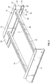
- a foldable cable tray 10 includes parallel first and second side rails 12, 14, a plurality of rungs 16 adapted to connect between the first and second side rails 12, 14 to fix a spacing therebetween, and a locking device 18.
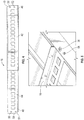
- the foldable cable tray 10 has a movable design/configuration between the plurality of rungs 16 and the first and second side rails 12, 14 that allows the foldable cable tray 10 to transit between unfolded ( Figure 1 ) and folded ( Figure 2 ) positions.
- each of the first and second side rails 12, 14 includes a generally vertical web 20 having first and second ends 22, 24, horizontal upper and lower flanges 26, 28 connected and separated by the web 20, and a shoulder 30 protruding outwardly from an inner surface 32 of the web 20.
- the upper and lower flanges 26, 28 are disposed at first and second ends 22, 24 of the web 20, respectively, and are substantially perpendicular to the first and second side rails 12, 14, respectively.
- the lower flange 28 includes a plurality of lower flange mounting holes 34 through which a movement device 36 may be inserted from the bottom of each of the plurality of lower flange mounting holes 34 to provide pivotal movement for the plurality of rungs 16.
- the movement device 36 could be a riveted joint or other device suitable for providing pivotal movement.
- the plurality of lower flange mounting holes 34 in the lower flange 28 are uniformly spaced apart at a predetermined interval across the entire length of the lower flange 28.
- a plurality of lower flange locking holes 38 are defined in the lower flange 28 each of which is positioned closely adjacent to each corresponding lower flange mounting hole 34.
- the locking device 18 may be inserted through any one of the plurality of lower flange locking holes 38 to secure the plurality of rungs 16 to the first and second side rails 12, 14 and prevent the plurality of rungs 16 from moving.
- the locking device 18 is applied to the first and last rungs to secure the plurality of rungs 16.
- the plurality of lower flange locking holes 38 are uniformly spaced apart at a predetermined interval across the entire length of the lower flange 28.
- the shoulder 30 is formed integrally from the inner surface 32 of the web 20 between the upper and lower flanges 26, 28 and extends across the entire length of the web 20. Spacing between the shoulder 30 and lower flange 28 is dimensioned to closely fit end portions of the plurality of rungs 16 therebetween.
- each of the plurality of rungs 16 includes a first rung member 42, a second rung member 44 and a rung locking device a first rung member 42, a second rung member.
- Contours of the first and second rung members 42, 44 are substantially identical except that the second rung member 44 is slightly smaller, thereby allowing the second rung member 44 to be fitted within the first rung member 42 and slidable therewithin.
- the second rung member 44 is slidably mounted for telescopic movement within the first rung member 42 such that it can be retracted or extended, as desired.
- this telescopic movement of the plurality of rungs 16 allows the foldable cable tray 10 to have a variable width during
- each of the plurality of rungs is an elongated channel extending between opposite ends (not shown).
- each of the plurality of rungs 16 is movably attached at a first end portion 46 of the first rung member 42 and a second end portion 48 of the second rung member 44 to the first and second side rails 12, 14, respectively.
- This movable connection with the first and second side rails 12, 14 allows each rung 16 to have pivotal movement therewith.
- the first and second end portions 46, 48 include a first angular cut 49 and a second angular cut 51, respectively, to allow each of the plurality of rungs 16 to pivotally move with the side rails 12, 14.
- the pivotal movement permits the foldable cable tray 10 to transit between the unfolded and folded positions.
- the plurality of rungs 16 are substantially perpendicular to each of the first and second side rails 12, 14, whereas in the folded position, the plurality of rungs 16 are near parallel to each of the first and second side rails 12, 14.
- a first rung mounting hole 50 and a first rung locking hole 52 are defined at the first end portion 46 of the first rung member 42, and a second rung mounting hole 54 and a second rung locking hole 56 are defined at the second end portion 48 of the second rung member 44.
- the first and second rung mounting holes 50, 54 are aligned with one of the plurality of lower flange mounting holes 34 in the first and second side rails 12, 14, respectively.
- the movement device 36 is then inserted through the aligned holes 34, 50, 54 to movably attach each of the plurality of rungs 16 and enable pivotal movement of each of the plurality of rungs 16 therewith.
- the foldable cable tray 10 is designed and configured to include a locking pin 58 as the locking device 18.
- the foldable cable tray 10 can be configured to include a bolt and nut device ( Figure 6 ) 60, locking rod device ( Figure 7 ) 62, locking tab device ( Figure 8 ) 64, L-bracket with channel nut and bolts device ( Figure 9 ) 66, L-bracket with securing flange device ( Figure 10 ) 68, locking clamp with bolt and nut device ( Figure 11 ) 70, or L-bracket with locking tab device ( Figure 12 ) 72.
- the first side rail 12, second side rail 14 and plurality of rungs 16 are made of one or more materials having suitable properties for a desired application, including strength, weight, rigidity, etc. Metal is generally preferred. Additionally, while each side rail 12, 14 is preferably in I-shape, it will be appreciated that other designs and configurations could be used for each side rail 12, 14 such as a C-shape or Z-shape, as deemed suitable for a given application factors.
- the first side rail 12, second side rail 14, and web 20 have substantially flat surfaces.
- the first and second side rails 12, 14 are substantially identical. Additionally, the upper and lower flanges 26, 28 are substantially identical.
- the foldable cable tray 10 In use of the foldable cable tray 10, first, the foldable cable tray 10 is arranged in the unfolded position such that the plurality of rungs 16 are perpendicular to each of the first and second side rails 12, 14. Then, an installer adjusts the plurality of rungs 16 to set a desired width of the foldable cable tray 10 by extending or retracting the plurality of rungs 16. Once the installer has set the desired width, the locking device 18 is applied to secure the plurality of rungs 16 to the first and second side rails 12, 14 in a fixed manner.
- a foldable cable tray according to the present invention allows the foldable cable tray to be shipped efficiently and conveniently, while reducing space needed for transportation.
Landscapes
- Engineering & Computer Science (AREA)
- General Engineering & Computer Science (AREA)
- Architecture (AREA)
- Civil Engineering (AREA)
- Structural Engineering (AREA)
- Mechanical Engineering (AREA)
- Details Of Indoor Wiring (AREA)
Description
- The present invention relates to cable trays, and more particularly, to foldable cable trays configured for ease of transportation and for storage.
- A cable tray supports electric cables used for power distribution and communication in the wiring of various facilities or commercial buildings. Generally, each of cable trays currently available in the market includes a pair of parallel side rails and a plurality of transverse rungs secured between the parallel side rails to fix the spacing between them. These rungs are typically welded or bolted to the side rails in a fixed manner such that there cannot be any movement between the rungs and side rails. Because of this rigid design and configuration of the available cable trays, shipping of the cable trays is normally performed by stacking the cable trays one over the other, which creates large amounts of air volume. Thus, this shipping method is inefficient and not desirable. Relevant prior art is disclosed in
NL7904309 GB1253577 WO2008120247 . - Accordingly, although various cable trays are available currently in the market, further improvements are possible to efficiently transport the cable trays.
- The cable tray of the present invention is according claim 1.
- In use of the foldable cable tray according to the invention, first, the foldable cable tray is arranged from the folded into the unfolded position such that the plurality of rungs are perpendicular to each of the first and second side rails. Then, an installer adjusts the plurality of rungs to set a desired width of the foldable cable tray by extending or retracting the plurality of rungs. Once the installer has set the desired width, the locking device is applied to secure the plurality of rungs to the first and second side rails in a fixed manner.
- From the foregoing, it will be appreciated that a foldable cable tray according to the present invention allows the foldable cable tray to be shipped efficiently and conveniently, while reducing space needed for transportation.
- In a possible embodiment of the foldable cable tray according to the invention, each of the plurality of rungs includes: a first rung member having opposite ends; and a second rung member having opposite ends, the second rung member slidably mounted within the first rung member for telescopic movement such that each of the plurality of rungs can be retracted or extended.
- According to the invention each of the plurality of rungs is movably attached at a first end portion of the first rung member and a second end portion of the second rung member to the first and second side rails, respectively.
- According to the invention a first rung mounting hole, a first rung locking hole and a first angular cut are defined at the first end portion of the first rung member.
- According to the invention a second rung mounting hole, a second rung locking hole and a second angular cut are defined at the second end portion of the second rung member.
- According to the invention a movement device is inserted through each of the first and second rung mounting holes to attach each of the plurality of rungs to the first and second side rails, enabling pivotal movement of each of the plurality of rungs therewith.
- In a further embodiment, the movement device is a riveted joint or the likes.
- In a possible embodiment of the foldable cable tray according to the invention, the locking device is a locking pin, bolt and nut, locking rod, locking tab, L-bracket with channel nut and bolt, L-bracket with securing flange, locking clamp with bolt and nut, or L-bracket with locking tab.
- In a possible embodiment of the foldable cable tray according to the invention, in the unfolded position, the plurality of rungs are substantially perpendicular to each of the first and second side rails.
- In a possible embodiment of the foldable cable tray according to the invention, in the folded position, the plurality of rungs are near parallel to each of the first and second side rails.
- In a possible embodiment of the foldable cable tray according to the invention, each of the first and second side rails includes: a web having first and second ends; and an upper flange disposed at the first end of the web; and a lower flange disposed at the second end of the web, wherein the upper and lower flanges are substantially perpendicular to the web.
- In a further embodiment the lower flange defines a plurality of lower flange mounting holes through which the movement device is inserted from the bottom of each of the plurality of lower flange mounting holes to provide pivotal movement for the plurality of rungs.
- According to the invention the lower flange defines a plurality of lower flange locking holes through which the locking device is inserted to lock the plurality of rungs to the first and second side rails.
- In a further embodiment, each of the lower flange locking hole is positioned closely adjacent to each corresponding lower flange mounting hole.
- In a further embodiment, the plurality of lower flange mounting holes are uniformly spaced apart at a predetermined interval across the entire length of the lower flange.
- In a further embodiment the plurality of lower flange locking holes are uniformly spaced apart at a predetermined interval across the entire length of the lower flange.
- In a further embodiment a shoulder is formed integrally from the inner surface of the web between the upper and lower flanges and extends across the entire length of the web.
- Another aspect of the invention relates to a method of installing a foldable cable tray includes unfolding the foldable cable tray, adjusting a plurality of rungs to set a desired width of the foldable cable tray by retracting or extending the plurality of rungs, and applying a locking device to affix the plurality of rungs to side rails.
- In this method the plurality of rungs may be telescopic.
- In this method the locking device may be a locking pin, bolt and nut, locking rod, locking tab, L-bracket with channel nut and bolt, L-bracket with securing flange, locking clamp with bolt and nut, or L-bracket with locking tab.
- These and other aspects of the present invention will be better understood in view of the drawings and following detailed description.
-
-
Figure 1 is a perspective view of the foldable cable tray, according to an embodiment of the present invention, in an unfolded position; -
Figure 2 is a perspective view of the foldable cable tray inFigure 1 in a folded position; -
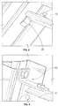
Figure 3 a partially-exploded perspective view of the foldable cable tray inFigure 1 ; -
Figure 4 is a perspective view of the rung inFigure 1 ; -
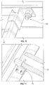
Figure 5 is a perspective view of the foldable cable tray ofFigure 1 with the locking pin as a locking device; -
Figure 6 is a perspective view of the foldable cable tray with the bolt and nut as a locking device; -
Figure 7 is a perspective view of the foldable cable tray with the locking rod as a locking device; -
Figure 8 is a perspective view of the foldable cable tray of with the locking tabs as a locking device; -
Figure 9 is a perspective view of the foldable cable tray with the L-bracket with channel nut and bolts as a locking device; -
Figure 10 is a perspective view of the foldable cable tray with the L-bracket with securing flange as a locking device; -
Figure 11 is a perspective view of the foldable cable tray with the locking clamp with bolt and nut as a locking device; and -
Figure 12 is a perspective view of the foldable cable tray with the L-bracket with locking tab as a locking device. - According to an embodiment of the present invention, referring to
Figures 1-3 , afoldable cable tray 10 includes parallel first andsecond side rails rungs 16 adapted to connect between the first andsecond side rails locking device 18. Thefoldable cable tray 10 has a movable design/configuration between the plurality ofrungs 16 and the first andsecond side rails foldable cable tray 10 to transit between unfolded (Figure 1 ) and folded (Figure 2 ) positions. - Referring to more particularly
Figure 3 , each of the first andsecond side rails vertical web 20 having first andsecond ends lower flanges web 20, and ashoulder 30 protruding outwardly from aninner surface 32 of theweb 20. The upper andlower flanges second ends web 20, respectively, and are substantially perpendicular to the first andsecond side rails - Referring again to
Figure 3 , in the depicted embodiment, thelower flange 28 includes a plurality of lowerflange mounting holes 34 through which amovement device 36 may be inserted from the bottom of each of the plurality of lowerflange mounting holes 34 to provide pivotal movement for the plurality ofrungs 16. Themovement device 36 could be a riveted joint or other device suitable for providing pivotal movement. The plurality of lowerflange mounting holes 34 in thelower flange 28 are uniformly spaced apart at a predetermined interval across the entire length of thelower flange 28. - In addition, a plurality of lower
flange locking holes 38 are defined in thelower flange 28 each of which is positioned closely adjacent to each corresponding lowerflange mounting hole 34. When thefoldable cable tray 10 is in the unfolded position, thelocking device 18, as will be describe in greater detail below, may be inserted through any one of the plurality of lowerflange locking holes 38 to secure the plurality ofrungs 16 to the first andsecond side rails rungs 16 from moving. Preferably, thelocking device 18 is applied to the first and last rungs to secure the plurality ofrungs 16. Similar to the plurality of lowerflange mounting holes 34, the plurality of lowerflange locking holes 38 are uniformly spaced apart at a predetermined interval across the entire length of thelower flange 28. - The
shoulder 30 is formed integrally from theinner surface 32 of theweb 20 between the upper andlower flanges web 20. Spacing between theshoulder 30 andlower flange 28 is dimensioned to closely fit end portions of the plurality ofrungs 16 therebetween. - Referring to
Figure 4 , in the depicted embodiment, each of the plurality ofrungs 16 includes afirst rung member 42, asecond rung member 44 and a rung locking device afirst rung member 42, a second rung member. Contours of the first andsecond rung members second rung member 44 is slightly smaller, thereby allowing thesecond rung member 44 to be fitted within thefirst rung member 42 and slidable therewithin. In other words, thesecond rung member 44 is slidably mounted for telescopic movement within thefirst rung member 42 such that it can be retracted or extended, as desired. Advantageously, this telescopic movement of the plurality ofrungs 16 allows thefoldable cable tray 10 to have a variable width during - its installation. Once a desired width is set, the rung locking device (not shown) may be applied to secure the first and
second rung members - Referring to
Figures 3 and4 , each of the plurality ofrungs 16 is movably attached at afirst end portion 46 of thefirst rung member 42 and asecond end portion 48 of thesecond rung member 44 to the first and second side rails 12, 14, respectively. This movable connection with the first and second side rails 12, 14 allows eachrung 16 to have pivotal movement therewith. The first andsecond end portions angular cut 49 and a second angular cut 51, respectively, to allow each of the plurality ofrungs 16 to pivotally move with the side rails 12, 14. As stated above, the pivotal movement permits thefoldable cable tray 10 to transit between the unfolded and folded positions. When thefoldable cable tray 10 is in the unfolded position, the plurality ofrungs 16 are substantially perpendicular to each of the first and second side rails 12, 14, whereas in the folded position, the plurality ofrungs 16 are near parallel to each of the first and second side rails 12, 14. - A first
rung mounting hole 50 and a firstrung locking hole 52 are defined at thefirst end portion 46 of thefirst rung member 42, and a secondrung mounting hole 54 and a secondrung locking hole 56 are defined at thesecond end portion 48 of thesecond rung member 44. To secure each of the plurality ofrungs 16, the first and secondrung mounting holes flange mounting holes 34 in the first and second side rails 12, 14, respectively. Themovement device 36 is then inserted through the alignedholes rungs 16 and enable pivotal movement of each of the plurality ofrungs 16 therewith. - In the depicted embodiment, as shown in
Figure 5 , thefoldable cable tray 10 is designed and configured to include a lockingpin 58 as the lockingdevice 18. Alternately, a variety of other designs and configurations for thelocking device 18 could be implemented within thefoldable cable tray 10. For example, thefoldable cable tray 10 can be configured to include a bolt and nut device (Figure 6 ) 60, locking rod device (Figure 7 ) 62, locking tab device (Figure 8 ) 64, L-bracket with channel nut and bolts device (Figure 9 ) 66, L-bracket with securing flange device (Figure 10 ) 68, locking clamp with bolt and nut device (Figure 11 ) 70, or L-bracket with locking tab device (Figure 12 ) 72. - The
first side rail 12,second side rail 14 and plurality ofrungs 16 are made of one or more materials having suitable properties for a desired application, including strength, weight, rigidity, etc. Metal is generally preferred. Additionally, while eachside rail side rail first side rail 12,second side rail 14, andweb 20 have substantially flat surfaces. The first and second side rails 12, 14 are substantially identical. Additionally, the upper andlower flanges - In use of the
foldable cable tray 10, first, thefoldable cable tray 10 is arranged in the unfolded position such that the plurality ofrungs 16 are perpendicular to each of the first and second side rails 12, 14. Then, an installer adjusts the plurality ofrungs 16 to set a desired width of thefoldable cable tray 10 by extending or retracting the plurality ofrungs 16. Once the installer has set the desired width, the lockingdevice 18 is applied to secure the plurality ofrungs 16 to the first and second side rails 12, 14 in a fixed manner. - From the foregoing, it will be appreciated that a foldable cable tray according to the present invention allows the foldable cable tray to be shipped efficiently and conveniently, while reducing space needed for transportation.
- In general, the foregoing description is provided for exemplary and illustrative purposes; the present invention is not necessarily limited thereto. Rather, those skilled in the art will appreciate that additional modifications, as well as adaptations for particular circumstances, will fall within the scope of the invention as herein shown and described and of the claims appended hereto.
Claims (13)
- A foldable cable tray (10) comprising:a first side rail (12);a second side rail (14), the second side rail (14) parallel to the first side rail (12);each of the first and the second side rails (12, 14) including a web (20) and a lower flange (28);each of the lower flanges (28) comprising a plurality of lower flange locking holes (38) and a plurality of lower flange mounting holes (34);a plurality of rungs (16) movably connected to the first and second side rails (12, 14) to transit the foldable cable tray (10) between unfolded and folded positions;
each of the plurality of rungs (16) comprising a rung mounting hole (50, 54) and a rung locking hole (52, 56) at a first end portion (46) and at a second end portion (48) thereof;a locking device (18) configured to lock each of the plurality of rungs (16) to the lower flange (28) of the first and second side rails (12, 14) by inserting the locking device (18) through the lower flange locking hole (38) and the rung locking hole (52, 56) when the foldable cable tray (10) is in the unfolded position anda plurality of movement devices (36), each movement device (36) of the plurality of movement devices (36) being secured in the rung mounting hole (50, 54) of a rung (16) of the plurality of rungs (16) and to the lower flange (28) of the first and second side rails (12, 14) to enable pivotal movement of each of the plurality of rungs (16) as the foldable cable tray (10) is displaced between unfolded and folded positions, the locking device (18) being insertable into both the lower flange locking hole (38) and the rung locking hole (52, 56) upon the foldable cable tray (10) being displaced to the unfolded position; and wherein the foldable cable tray (10) is lockable in the unfolded position upon insertion of the locking device (18) through any one of the plurality of lower flange locking holes (38) in the lower flange (28) and into an adjacent rung locking hole (52, 56) of any of the plurality of rungs (16) to prevent the plurality of rungs (16) from being moved;characterized in that a first angular cut (49) and a second angular cut (51) are defined at the first end portion (46) and at the second end portion (48) of each of the plurality of rung members (16) respectively, to allow them to pivotally move with respect to the side rails (12, 4). - The foldable cable tray of claim 1, wherein each of the plurality of rungs (16) includes:a first rung member (42) having opposite ends; anda second rung member (44) having opposite ends, the second rung member (44) slidably mounted within the first rung member (42) for telescopic movement such that each of the plurality of rungs (16) can be retracted or extended.
- The foldable cable tray of claim 2, wherein the first rung mounting hole (50), the first rung locking hole (52) and a first angular cut (49) are defined at the first end portion (46) of the first rung member (42), the first angular cut (49) configured to allow pivotal displacement of the rung (16).
- The foldable cable tray of claim 2 or 3, wherein the second rung mounting hole (54), the second rung locking hole (56) and a second angular cut (51) are defined at the second end portion (48) of the second rung member (44), the second angular cut (49) configured to allow pivotal displacement of the rung (16).
- The foldable cable tray of claim 4, wherein the movement device (36) is a riveted joint or the likes.
- The foldable cable tray of any one of the preceding claims, wherein the locking device (18) is a locking pin (58), bolt and nut (60), locking rod (62), locking tab(64), L-bracket with channel nut and bolt (66), L-bracket with securing flange (68), locking clamp with bolt and nut (70), or L-bracket with locking tab (72).
- The foldable cable tray of any one of the preceding claims, wherein, in the unfolded position, the plurality of rungs (16) are perpendicular to each of the first and second side rails (12, 14), and/or, wherein, in the folded position, the plurality of rungs (16) are near parallel to each of the first and second side rails (12, 14).
- The foldable cable tray of any one of the preceding claims, wherein the web (20) has first and second ends (22, 24);
an upper flange (26) is disposed at the first end (22) of the web (20); and
the lower flange (28) is disposed at the second end (24) of the web (20), and
wherein the upper and lower flanges (26, 28) are perpendicular to the web (20). - The foldable cable tray of claim 8, wherein each of the lower flange locking holes (38) is positioned closely adjacent to each corresponding lower flange mounting hole (34).
- The foldable cable tray of claim 9, wherein the plurality of lower flange mounting holes (34) are uniformly spaced apart at a predetermined interval across the entire length of the lower flange (28).
- The foldable cable tray of claim 9, wherein the plurality of lower flange locking holes (38) are uniformly spaced apart at a predetermined interval across the entire length of the lower flange (28).
- The foldable cable tray of any one of the claims 8-11, wherein a shoulder (30) is formed integrally from the inner surface (32) of the web (20) between the upper and lower flanges (26, 28) and extends across the entire length of the web (20).
- A method of installing the foldable cable tray (10) of claim 1, the method comprising:unfolding the foldable cable tray (10);adjusting the plurality of rungs (16) to set a desired width of the foldable cable tray (10) by retracting or extending the plurality of rungs (16), wherein a first angular cut (49) and a second angular cut (51) are defined at end portions (46, 48) of each of the rungs (16) to allow each of the plurality of rungs (16) to pivotally move with respect to the side rails (12, 14);selecting, from the plurality of flange locking holes (38) in both of the first and second rails (12, 14), a flange locking hole (38) in the first side rail (12) and a flange hole (38) in the second side rail (14) that are to each receive insertion of the locking device (18); andapplying the locking device (18) to the selected flange hole (38) and in the first side rail (12) and another locking device (18) in the second side rail (14) to affix the plurality of rungs (16) to the side rails (12, 14).
Applications Claiming Priority (1)
| Application Number | Priority Date | Filing Date | Title |
|---|---|---|---|
| US201662347280P | 2016-06-08 | 2016-06-08 |
Publications (2)
| Publication Number | Publication Date |
|---|---|
| EP3255746A1 EP3255746A1 (en) | 2017-12-13 |
| EP3255746B1 true EP3255746B1 (en) | 2020-09-30 |
Family
ID=59055008
Family Applications (1)
| Application Number | Title | Priority Date | Filing Date |
|---|---|---|---|
| EP17174944.3A Active EP3255746B1 (en) | 2016-06-08 | 2017-06-08 | Foldable cable tray |
Country Status (3)
| Country | Link |
|---|---|
| US (1) | US10128642B2 (en) |
| EP (1) | EP3255746B1 (en) |
| SG (1) | SG10201704653QA (en) |
Families Citing this family (4)
| Publication number | Priority date | Publication date | Assignee | Title |
|---|---|---|---|---|
| US10128642B2 (en) | 2016-06-08 | 2018-11-13 | Thomas & Betts International Llc | Foldable cable tray |
| CN107831807B (en) * | 2017-10-26 | 2020-06-19 | 合肥超越电器有限责任公司 | Temperature controller with lateral folding protection concentrator |
| CN112332328A (en) * | 2020-10-22 | 2021-02-05 | 浙江一舟电子科技股份有限公司 | Wiring support capable of adjusting width of wire groove |
| CA3138070A1 (en) * | 2021-11-08 | 2023-05-08 | Abb Schweiz Ag | Cable tray |
Family Cites Families (43)
| Publication number | Priority date | Publication date | Assignee | Title |
|---|---|---|---|---|
| US3414081A (en) | 1967-05-18 | 1968-12-03 | Albert F. Wedvik | Contractible ladder |
| GB1253577A (en) | 1969-07-15 | 1971-11-17 | Boucher And Company Ltd | Improvements relating to tray or duct members for supporting service cables and the like |
| US3598349A (en) | 1969-11-13 | 1971-08-10 | Dracon Ind | Cable trough |
| NL7904309A (en) | 1979-05-31 | 1980-12-02 | Gouda Holland Holdings Sa | Ladder shaped frame for cable trunking - has adjustable members for anchoring brackets on upright of longitudinal members with locking pins |
| US4463829A (en) | 1982-02-25 | 1984-08-07 | Ariy Grin | Foldable ladder |
| US4678060A (en) | 1986-08-25 | 1987-07-07 | Pugliese Joseph A | Collapsible ladder device |
| US5201488A (en) | 1988-12-23 | 1993-04-13 | Hadbavny David L | Telescoping tubular body |
| US5060757A (en) | 1990-07-11 | 1991-10-29 | Naturaland Trust | Adjustable rungs for ladder |
| US5060892A (en) | 1990-09-24 | 1991-10-29 | Glen Dougherty | Plumbing hanger bracket assembly |
| DE9115650U1 (en) | 1991-12-18 | 1992-03-12 | Yang, Chin-Hui, Hsin Tien City, Taipeh | Adjustable conductor cable ceiling duct |
| US5465929A (en) | 1993-08-19 | 1995-11-14 | B-Line Systems, Inc. | Ladder-type cable tray system |
| US5593115A (en) | 1994-06-15 | 1997-01-14 | Lewis; James M. | Pipe hanger |
| US6402096B1 (en) | 1997-11-06 | 2002-06-11 | Sioux Chief Mfg. Co., Inc. | Apparatus for supporting conduit between building members |
| US6070742A (en) | 1998-10-28 | 2000-06-06 | Dell Usa, L.P. | Multi-segment, nesting, low profile cable management arm |
| US6129179A (en) | 1999-09-10 | 2000-10-10 | Rooney; William V. | Laterally extensible ladder |
| US6739795B1 (en) | 2000-05-25 | 2004-05-25 | Adc Telecommunications, Inc. | Telescoping trough |
| US6457559B1 (en) | 2000-07-26 | 2002-10-01 | Mark R. Schlueter | Foldable ladder |
| US6536558B2 (en) | 2001-02-16 | 2003-03-25 | Harold E. Price | Folding ladder |
| US6547192B2 (en) * | 2001-02-26 | 2003-04-15 | Cooper Technologies Company | Cable tray junction |
| US6585195B2 (en) * | 2001-04-25 | 2003-07-01 | Adc Telecommunications, Inc. | Cable management system including variable segments |
| US6598753B2 (en) | 2001-10-12 | 2003-07-29 | Tseng Yi Ming | Foldable umbrella stand |
| US6644601B2 (en) | 2001-10-16 | 2003-11-11 | General Electric Company | Cable tray stand |
| US6715584B2 (en) | 2002-08-05 | 2004-04-06 | Valere R. Ostyn | Escape ladder |
| US7554819B2 (en) * | 2004-10-15 | 2009-06-30 | King Slide Works Co., Ltd. | Cable management arm assembly |
| US7712615B2 (en) * | 2004-10-15 | 2010-05-11 | King Slide Works Co., Ltd. | Support slide assembly for cable management arm |
| CN1995684A (en) | 2006-12-31 | 2007-07-11 | 天津市金锚集团有限责任公司 | Collapsible single ladder |
| WO2008120247A1 (en) | 2007-03-29 | 2008-10-09 | Top Glass S.P.A. | Cable conduit for electrical cables amd similar objects |
| TW200912172A (en) | 2007-09-06 | 2009-03-16 | King Slide Works Co Ltd | Supporting device of wire-arranging frame |
| WO2010059743A1 (en) * | 2008-11-19 | 2010-05-27 | Hoffman Enclosures, Inc. | Variable angle fitting |
| DK200900012U3 (en) | 2008-11-28 | 2009-05-25 | Nielsen Otto Martinus | Collapsible ladder |
| US20100181440A1 (en) * | 2009-01-21 | 2010-07-22 | Ortronics, Inc. | Articulated Cable Management Systems and Methods For Use Thereof |
| US8540090B2 (en) | 2009-05-19 | 2013-09-24 | Panduit Corp. | Telescoping wire cable tray system |
| US20120037453A1 (en) | 2010-08-16 | 2012-02-16 | Francisco Flecha | Collapsible ladder and method |
| US8839906B1 (en) | 2011-10-28 | 2014-09-23 | Ricky Jason Furr | Adjustable span stabilizer for ladders |
| TWM449433U (en) | 2012-06-20 | 2013-03-21 | Echostreams Innovative Solutions | Wire organizing holder and its casing segment |
| US8959843B2 (en) | 2012-11-12 | 2015-02-24 | Eco-Built Homes, LLC | Telescoping frame system for portable home or other structure |
| US8844212B1 (en) | 2013-05-18 | 2014-09-30 | Eco-Built Homes, LLC | Telescoping frame system for portable home or other structure |
| US8555558B1 (en) | 2012-11-12 | 2013-10-15 | Eco-Built Homes LLC | Telescoping frame system for portable home or other structure |
| US9022326B2 (en) | 2013-03-15 | 2015-05-05 | Securus, Inc. | Pipe holder and support |
| CN203850763U (en) | 2014-04-09 | 2014-09-24 | 安徽中德机床股份有限公司 | Foldable cable tray |
| US9068394B1 (en) | 2014-10-10 | 2015-06-30 | Grover J. Geiselman, III | Space saving ladder |
| TWI544861B (en) * | 2015-02-17 | 2016-08-01 | The improved structure of the management device | |
| US10128642B2 (en) | 2016-06-08 | 2018-11-13 | Thomas & Betts International Llc | Foldable cable tray |
-
2017
- 2017-06-01 US US15/610,976 patent/US10128642B2/en active Active
- 2017-06-07 SG SG10201704653QA patent/SG10201704653QA/en unknown
- 2017-06-08 EP EP17174944.3A patent/EP3255746B1/en active Active
Non-Patent Citations (1)
| Title |
|---|
| None * |
Also Published As
| Publication number | Publication date |
|---|---|
| SG10201704653QA (en) | 2018-01-30 |
| EP3255746A1 (en) | 2017-12-13 |
| US10128642B2 (en) | 2018-11-13 |
| US20170358910A1 (en) | 2017-12-14 |
Similar Documents
| Publication | Publication Date | Title |
|---|---|---|
| US10128642B2 (en) | Foldable cable tray | |
| US10145128B2 (en) | Interlocking work platform system and method | |
| US20170159948A1 (en) | Supporting an object at a window of a building by applying opposing forces to an interior surface and an exterior surface of the building | |
| US11767162B2 (en) | Modular facility formation system and shipping method | |
| US20130213907A1 (en) | Framework of an electrical panel or enclosure | |
| US20100154351A1 (en) | Tower of a wind power plant | |
| KR20160117473A (en) | Bottom assembly for the frame of a switch cabinet | |
| US20170222416A1 (en) | Mounting brace assembly for mounting an electrical box | |
| US9915096B2 (en) | Garage door ladder storage devices and methods thereof | |
| US20170171650A1 (en) | Connection device for loudspeaker boxes, arrangement of loudspeaker boxes suspended below one another, and method and transport cart for setting up the arrangement | |
| US8616513B2 (en) | Bracket having overhanging support elements for supporting an electrical box | |
| US20240364084A1 (en) | Splice plate assembly for cable tray | |
| CA2690024A1 (en) | Dynamic hinge for ladder | |
| US8387339B2 (en) | Adjustable wall support system and method | |
| EP1696084A1 (en) | Telescopic rail for use in forming a guard or safety barrier for builders' trestles | |
| EP2709221B1 (en) | Cable track | |
| EP3607164B1 (en) | Ladder with telescopic stabilizer | |
| US20180127244A1 (en) | Elevator counterweight assembly | |
| US8702069B1 (en) | Guard rail system | |
| RS57935B1 (en) | Cable support segment connector as adapter for a cable support system | |
| GB2537440A (en) | A void safety system | |
| IT201900009891A1 (en) | Adjustable support platform. | |
| US20160326756A1 (en) | Platform system | |
| EP2962932A1 (en) | Bridge adapted for accessing an aircraft compartment via a manhole | |
| CN216301498U (en) | Rotor type aircraft support carrying platform |
Legal Events
| Date | Code | Title | Description |
|---|---|---|---|
| PUAI | Public reference made under article 153(3) epc to a published international application that has entered the european phase |
Free format text: ORIGINAL CODE: 0009012 |
|
| STAA | Information on the status of an ep patent application or granted ep patent |
Free format text: STATUS: REQUEST FOR EXAMINATION WAS MADE |
|
| 17P | Request for examination filed |
Effective date: 20170608 |
|
| AK | Designated contracting states |
Kind code of ref document: A1 Designated state(s): AL AT BE BG CH CY CZ DE DK EE ES FI FR GB GR HR HU IE IS IT LI LT LU LV MC MK MT NL NO PL PT RO RS SE SI SK SM TR |
|
| AX | Request for extension of the european patent |
Extension state: BA ME |
|
| RBV | Designated contracting states (corrected) |
Designated state(s): AL AT BE BG CH CY CZ DE DK EE ES FI FR GB GR HR HU IE IS IT LI LT LU LV MC MK MT NL NO PL PT RO RS SE SI SK SM TR |
|
| STAA | Information on the status of an ep patent application or granted ep patent |
Free format text: STATUS: EXAMINATION IS IN PROGRESS |
|
| 17Q | First examination report despatched |
Effective date: 20190506 |
|
| GRAP | Despatch of communication of intention to grant a patent |
Free format text: ORIGINAL CODE: EPIDOSNIGR1 |
|
| STAA | Information on the status of an ep patent application or granted ep patent |
Free format text: STATUS: GRANT OF PATENT IS INTENDED |
|
| RIC1 | Information provided on ipc code assigned before grant |
Ipc: H02G 3/06 20060101ALN20200305BHEP Ipc: E06C 1/383 20060101ALN20200305BHEP Ipc: H02G 3/04 20060101AFI20200305BHEP |
|
| INTG | Intention to grant announced |
Effective date: 20200402 |
|
| RIN1 | Information on inventor provided before grant (corrected) |
Inventor name: NASH, TYLER Inventor name: DINH, CONG THANH Inventor name: THOMAS, MATHEW Inventor name: CARDIN, DANIEL |
|
| GRAS | Grant fee paid |
Free format text: ORIGINAL CODE: EPIDOSNIGR3 |
|
| RIN1 | Information on inventor provided before grant (corrected) |
Inventor name: THOMAS, MATHEW Inventor name: DINH, CONG THANH Inventor name: CARDIN, DANIEL Inventor name: NASH, TYLER |
|
| GRAA | (expected) grant |
Free format text: ORIGINAL CODE: 0009210 |
|
| STAA | Information on the status of an ep patent application or granted ep patent |
Free format text: STATUS: THE PATENT HAS BEEN GRANTED |
|
| AK | Designated contracting states |
Kind code of ref document: B1 Designated state(s): AL AT BE BG CH CY CZ DE DK EE ES FI FR GB GR HR HU IE IS IT LI LT LU LV MC MK MT NL NO PL PT RO RS SE SI SK SM TR |
|
| REG | Reference to a national code |
Ref country code: CH Ref legal event code: EP Ref country code: GB Ref legal event code: FG4D |
|
| RIN1 | Information on inventor provided before grant (corrected) |
Inventor name: CARDIN, DANIEL Inventor name: NASH, TYLER Inventor name: DINH, CONG THANH Inventor name: THOMAS, MATHEW |
|
| REG | Reference to a national code |
Ref country code: AT Ref legal event code: REF Ref document number: 1319768 Country of ref document: AT Kind code of ref document: T Effective date: 20201015 |
|
| REG | Reference to a national code |
Ref country code: DE Ref legal event code: R096 Ref document number: 602017024450 Country of ref document: DE |
|
| REG | Reference to a national code |
Ref country code: IE Ref legal event code: FG4D |
|
| PG25 | Lapsed in a contracting state [announced via postgrant information from national office to epo] |
Ref country code: HR Free format text: LAPSE BECAUSE OF FAILURE TO SUBMIT A TRANSLATION OF THE DESCRIPTION OR TO PAY THE FEE WITHIN THE PRESCRIBED TIME-LIMIT Effective date: 20200930 Ref country code: BG Free format text: LAPSE BECAUSE OF FAILURE TO SUBMIT A TRANSLATION OF THE DESCRIPTION OR TO PAY THE FEE WITHIN THE PRESCRIBED TIME-LIMIT Effective date: 20201230 Ref country code: SE Free format text: LAPSE BECAUSE OF FAILURE TO SUBMIT A TRANSLATION OF THE DESCRIPTION OR TO PAY THE FEE WITHIN THE PRESCRIBED TIME-LIMIT Effective date: 20200930 Ref country code: FI Free format text: LAPSE BECAUSE OF FAILURE TO SUBMIT A TRANSLATION OF THE DESCRIPTION OR TO PAY THE FEE WITHIN THE PRESCRIBED TIME-LIMIT Effective date: 20200930 Ref country code: NO Free format text: LAPSE BECAUSE OF FAILURE TO SUBMIT A TRANSLATION OF THE DESCRIPTION OR TO PAY THE FEE WITHIN THE PRESCRIBED TIME-LIMIT Effective date: 20201230 Ref country code: GR Free format text: LAPSE BECAUSE OF FAILURE TO SUBMIT A TRANSLATION OF THE DESCRIPTION OR TO PAY THE FEE WITHIN THE PRESCRIBED TIME-LIMIT Effective date: 20201231 |
|
| REG | Reference to a national code |
Ref country code: AT Ref legal event code: MK05 Ref document number: 1319768 Country of ref document: AT Kind code of ref document: T Effective date: 20200930 |
|
| PG25 | Lapsed in a contracting state [announced via postgrant information from national office to epo] |
Ref country code: LV Free format text: LAPSE BECAUSE OF FAILURE TO SUBMIT A TRANSLATION OF THE DESCRIPTION OR TO PAY THE FEE WITHIN THE PRESCRIBED TIME-LIMIT Effective date: 20200930 Ref country code: RS Free format text: LAPSE BECAUSE OF FAILURE TO SUBMIT A TRANSLATION OF THE DESCRIPTION OR TO PAY THE FEE WITHIN THE PRESCRIBED TIME-LIMIT Effective date: 20200930 |
|
| REG | Reference to a national code |
Ref country code: NL Ref legal event code: MP Effective date: 20200930 |
|
| REG | Reference to a national code |
Ref country code: LT Ref legal event code: MG4D |
|
| PG25 | Lapsed in a contracting state [announced via postgrant information from national office to epo] |
Ref country code: EE Free format text: LAPSE BECAUSE OF FAILURE TO SUBMIT A TRANSLATION OF THE DESCRIPTION OR TO PAY THE FEE WITHIN THE PRESCRIBED TIME-LIMIT Effective date: 20200930 Ref country code: SM Free format text: LAPSE BECAUSE OF FAILURE TO SUBMIT A TRANSLATION OF THE DESCRIPTION OR TO PAY THE FEE WITHIN THE PRESCRIBED TIME-LIMIT Effective date: 20200930 Ref country code: LT Free format text: LAPSE BECAUSE OF FAILURE TO SUBMIT A TRANSLATION OF THE DESCRIPTION OR TO PAY THE FEE WITHIN THE PRESCRIBED TIME-LIMIT Effective date: 20200930 Ref country code: NL Free format text: LAPSE BECAUSE OF FAILURE TO SUBMIT A TRANSLATION OF THE DESCRIPTION OR TO PAY THE FEE WITHIN THE PRESCRIBED TIME-LIMIT Effective date: 20200930 Ref country code: CZ Free format text: LAPSE BECAUSE OF FAILURE TO SUBMIT A TRANSLATION OF THE DESCRIPTION OR TO PAY THE FEE WITHIN THE PRESCRIBED TIME-LIMIT Effective date: 20200930 Ref country code: RO Free format text: LAPSE BECAUSE OF FAILURE TO SUBMIT A TRANSLATION OF THE DESCRIPTION OR TO PAY THE FEE WITHIN THE PRESCRIBED TIME-LIMIT Effective date: 20200930 Ref country code: PT Free format text: LAPSE BECAUSE OF FAILURE TO SUBMIT A TRANSLATION OF THE DESCRIPTION OR TO PAY THE FEE WITHIN THE PRESCRIBED TIME-LIMIT Effective date: 20210201 |
|
| PG25 | Lapsed in a contracting state [announced via postgrant information from national office to epo] |
Ref country code: IS Free format text: LAPSE BECAUSE OF FAILURE TO SUBMIT A TRANSLATION OF THE DESCRIPTION OR TO PAY THE FEE WITHIN THE PRESCRIBED TIME-LIMIT Effective date: 20210130 Ref country code: PL Free format text: LAPSE BECAUSE OF FAILURE TO SUBMIT A TRANSLATION OF THE DESCRIPTION OR TO PAY THE FEE WITHIN THE PRESCRIBED TIME-LIMIT Effective date: 20200930 Ref country code: ES Free format text: LAPSE BECAUSE OF FAILURE TO SUBMIT A TRANSLATION OF THE DESCRIPTION OR TO PAY THE FEE WITHIN THE PRESCRIBED TIME-LIMIT Effective date: 20200930 Ref country code: AL Free format text: LAPSE BECAUSE OF FAILURE TO SUBMIT A TRANSLATION OF THE DESCRIPTION OR TO PAY THE FEE WITHIN THE PRESCRIBED TIME-LIMIT Effective date: 20200930 Ref country code: AT Free format text: LAPSE BECAUSE OF FAILURE TO SUBMIT A TRANSLATION OF THE DESCRIPTION OR TO PAY THE FEE WITHIN THE PRESCRIBED TIME-LIMIT Effective date: 20200930 |
|
| PG25 | Lapsed in a contracting state [announced via postgrant information from national office to epo] |
Ref country code: SK Free format text: LAPSE BECAUSE OF FAILURE TO SUBMIT A TRANSLATION OF THE DESCRIPTION OR TO PAY THE FEE WITHIN THE PRESCRIBED TIME-LIMIT Effective date: 20200930 |
|
| REG | Reference to a national code |
Ref country code: DE Ref legal event code: R097 Ref document number: 602017024450 Country of ref document: DE |
|
| PLBE | No opposition filed within time limit |
Free format text: ORIGINAL CODE: 0009261 |
|
| STAA | Information on the status of an ep patent application or granted ep patent |
Free format text: STATUS: NO OPPOSITION FILED WITHIN TIME LIMIT |
|
| PG25 | Lapsed in a contracting state [announced via postgrant information from national office to epo] |
Ref country code: DK Free format text: LAPSE BECAUSE OF FAILURE TO SUBMIT A TRANSLATION OF THE DESCRIPTION OR TO PAY THE FEE WITHIN THE PRESCRIBED TIME-LIMIT Effective date: 20200930 |
|
| 26N | No opposition filed |
Effective date: 20210701 |
|
| PG25 | Lapsed in a contracting state [announced via postgrant information from national office to epo] |
Ref country code: IT Free format text: LAPSE BECAUSE OF FAILURE TO SUBMIT A TRANSLATION OF THE DESCRIPTION OR TO PAY THE FEE WITHIN THE PRESCRIBED TIME-LIMIT Effective date: 20200930 |
|
| PG25 | Lapsed in a contracting state [announced via postgrant information from national office to epo] |
Ref country code: SI Free format text: LAPSE BECAUSE OF FAILURE TO SUBMIT A TRANSLATION OF THE DESCRIPTION OR TO PAY THE FEE WITHIN THE PRESCRIBED TIME-LIMIT Effective date: 20200930 |
|
| PG25 | Lapsed in a contracting state [announced via postgrant information from national office to epo] |
Ref country code: MC Free format text: LAPSE BECAUSE OF FAILURE TO SUBMIT A TRANSLATION OF THE DESCRIPTION OR TO PAY THE FEE WITHIN THE PRESCRIBED TIME-LIMIT Effective date: 20200930 |
|
| REG | Reference to a national code |
Ref country code: CH Ref legal event code: PL |
|
| REG | Reference to a national code |
Ref country code: BE Ref legal event code: MM Effective date: 20210630 |
|
| PG25 | Lapsed in a contracting state [announced via postgrant information from national office to epo] |
Ref country code: LU Free format text: LAPSE BECAUSE OF NON-PAYMENT OF DUE FEES Effective date: 20210608 |
|
| PG25 | Lapsed in a contracting state [announced via postgrant information from national office to epo] |
Ref country code: LI Free format text: LAPSE BECAUSE OF NON-PAYMENT OF DUE FEES Effective date: 20210630 Ref country code: IE Free format text: LAPSE BECAUSE OF NON-PAYMENT OF DUE FEES Effective date: 20210608 Ref country code: CH Free format text: LAPSE BECAUSE OF NON-PAYMENT OF DUE FEES Effective date: 20210630 |
|
| PG25 | Lapsed in a contracting state [announced via postgrant information from national office to epo] |
Ref country code: IS Free format text: LAPSE BECAUSE OF FAILURE TO SUBMIT A TRANSLATION OF THE DESCRIPTION OR TO PAY THE FEE WITHIN THE PRESCRIBED TIME-LIMIT Effective date: 20210130 |
|
| PG25 | Lapsed in a contracting state [announced via postgrant information from national office to epo] |
Ref country code: BE Free format text: LAPSE BECAUSE OF NON-PAYMENT OF DUE FEES Effective date: 20210630 |
|
| PG25 | Lapsed in a contracting state [announced via postgrant information from national office to epo] |
Ref country code: HU Free format text: LAPSE BECAUSE OF FAILURE TO SUBMIT A TRANSLATION OF THE DESCRIPTION OR TO PAY THE FEE WITHIN THE PRESCRIBED TIME-LIMIT; INVALID AB INITIO Effective date: 20170608 |
|
| PG25 | Lapsed in a contracting state [announced via postgrant information from national office to epo] |
Ref country code: CY Free format text: LAPSE BECAUSE OF FAILURE TO SUBMIT A TRANSLATION OF THE DESCRIPTION OR TO PAY THE FEE WITHIN THE PRESCRIBED TIME-LIMIT Effective date: 20200930 |
|
| PG25 | Lapsed in a contracting state [announced via postgrant information from national office to epo] |
Ref country code: MK Free format text: LAPSE BECAUSE OF FAILURE TO SUBMIT A TRANSLATION OF THE DESCRIPTION OR TO PAY THE FEE WITHIN THE PRESCRIBED TIME-LIMIT Effective date: 20200930 |
|
| PG25 | Lapsed in a contracting state [announced via postgrant information from national office to epo] |
Ref country code: MT Free format text: LAPSE BECAUSE OF FAILURE TO SUBMIT A TRANSLATION OF THE DESCRIPTION OR TO PAY THE FEE WITHIN THE PRESCRIBED TIME-LIMIT Effective date: 20200930 |
|
| PGFP | Annual fee paid to national office [announced via postgrant information from national office to epo] |
Ref country code: DE Payment date: 20250618 Year of fee payment: 9 |
|
| PGFP | Annual fee paid to national office [announced via postgrant information from national office to epo] |
Ref country code: GB Payment date: 20250618 Year of fee payment: 9 |
|
| PGFP | Annual fee paid to national office [announced via postgrant information from national office to epo] |
Ref country code: FR Payment date: 20250625 Year of fee payment: 9 |
|
| PG25 | Lapsed in a contracting state [announced via postgrant information from national office to epo] |
Ref country code: TR Free format text: LAPSE BECAUSE OF FAILURE TO SUBMIT A TRANSLATION OF THE DESCRIPTION OR TO PAY THE FEE WITHIN THE PRESCRIBED TIME-LIMIT Effective date: 20200930 |