EP3255705A1 - Electrode assembly including electrode plates with electrode plate extensions - Google Patents
Electrode assembly including electrode plates with electrode plate extensions Download PDFInfo
- Publication number
- EP3255705A1 EP3255705A1 EP17174483.2A EP17174483A EP3255705A1 EP 3255705 A1 EP3255705 A1 EP 3255705A1 EP 17174483 A EP17174483 A EP 17174483A EP 3255705 A1 EP3255705 A1 EP 3255705A1
- Authority
- EP
- European Patent Office
- Prior art keywords
- electrode
- electrode plate
- tab
- separator
- positive
- Prior art date
- Legal status (The legal status is an assumption and is not a legal conclusion. Google has not performed a legal analysis and makes no representation as to the accuracy of the status listed.)
- Granted
Links
Images

Classifications
-
- H—ELECTRICITY
- H01—ELECTRIC ELEMENTS
- H01M—PROCESSES OR MEANS, e.g. BATTERIES, FOR THE DIRECT CONVERSION OF CHEMICAL ENERGY INTO ELECTRICAL ENERGY
- H01M10/00—Secondary cells; Manufacture thereof
- H01M10/04—Construction or manufacture in general
- H01M10/0436—Small-sized flat cells or batteries for portable equipment
-
- H—ELECTRICITY
- H01—ELECTRIC ELEMENTS
- H01M—PROCESSES OR MEANS, e.g. BATTERIES, FOR THE DIRECT CONVERSION OF CHEMICAL ENERGY INTO ELECTRICAL ENERGY
- H01M10/00—Secondary cells; Manufacture thereof
- H01M10/05—Accumulators with non-aqueous electrolyte
- H01M10/052—Li-accumulators
- H01M10/0525—Rocking-chair batteries, i.e. batteries with lithium insertion or intercalation in both electrodes; Lithium-ion batteries
-
- H—ELECTRICITY
- H01—ELECTRIC ELEMENTS
- H01M—PROCESSES OR MEANS, e.g. BATTERIES, FOR THE DIRECT CONVERSION OF CHEMICAL ENERGY INTO ELECTRICAL ENERGY
- H01M10/00—Secondary cells; Manufacture thereof
- H01M10/04—Construction or manufacture in general
- H01M10/0431—Cells with wound or folded electrodes
-
- H—ELECTRICITY
- H01—ELECTRIC ELEMENTS
- H01M—PROCESSES OR MEANS, e.g. BATTERIES, FOR THE DIRECT CONVERSION OF CHEMICAL ENERGY INTO ELECTRICAL ENERGY
- H01M10/00—Secondary cells; Manufacture thereof
- H01M10/04—Construction or manufacture in general
- H01M10/045—Cells or batteries with folded plate-like electrodes
-
- H—ELECTRICITY
- H01—ELECTRIC ELEMENTS
- H01M—PROCESSES OR MEANS, e.g. BATTERIES, FOR THE DIRECT CONVERSION OF CHEMICAL ENERGY INTO ELECTRICAL ENERGY
- H01M10/00—Secondary cells; Manufacture thereof
- H01M10/05—Accumulators with non-aqueous electrolyte
- H01M10/058—Construction or manufacture
-
- H—ELECTRICITY
- H01—ELECTRIC ELEMENTS
- H01M—PROCESSES OR MEANS, e.g. BATTERIES, FOR THE DIRECT CONVERSION OF CHEMICAL ENERGY INTO ELECTRICAL ENERGY
- H01M10/00—Secondary cells; Manufacture thereof
- H01M10/05—Accumulators with non-aqueous electrolyte
- H01M10/058—Construction or manufacture
- H01M10/0583—Construction or manufacture of accumulators with folded construction elements except wound ones, i.e. folded positive or negative electrodes or separators, e.g. with "Z"-shaped electrodes or separators
-
- H—ELECTRICITY
- H01—ELECTRIC ELEMENTS
- H01M—PROCESSES OR MEANS, e.g. BATTERIES, FOR THE DIRECT CONVERSION OF CHEMICAL ENERGY INTO ELECTRICAL ENERGY
- H01M10/00—Secondary cells; Manufacture thereof
- H01M10/05—Accumulators with non-aqueous electrolyte
- H01M10/058—Construction or manufacture
- H01M10/0585—Construction or manufacture of accumulators having only flat construction elements, i.e. flat positive electrodes, flat negative electrodes and flat separators
-
- H—ELECTRICITY
- H01—ELECTRIC ELEMENTS
- H01M—PROCESSES OR MEANS, e.g. BATTERIES, FOR THE DIRECT CONVERSION OF CHEMICAL ENERGY INTO ELECTRICAL ENERGY
- H01M10/00—Secondary cells; Manufacture thereof
- H01M10/05—Accumulators with non-aqueous electrolyte
- H01M10/058—Construction or manufacture
- H01M10/0587—Construction or manufacture of accumulators having only wound construction elements, i.e. wound positive electrodes, wound negative electrodes and wound separators
-
- H—ELECTRICITY
- H01—ELECTRIC ELEMENTS
- H01M—PROCESSES OR MEANS, e.g. BATTERIES, FOR THE DIRECT CONVERSION OF CHEMICAL ENERGY INTO ELECTRICAL ENERGY
- H01M50/00—Constructional details or processes of manufacture of the non-active parts of electrochemical cells other than fuel cells, e.g. hybrid cells
- H01M50/40—Separators; Membranes; Diaphragms; Spacing elements inside cells
- H01M50/46—Separators, membranes or diaphragms characterised by their combination with electrodes
-
- H—ELECTRICITY
- H01—ELECTRIC ELEMENTS
- H01M—PROCESSES OR MEANS, e.g. BATTERIES, FOR THE DIRECT CONVERSION OF CHEMICAL ENERGY INTO ELECTRICAL ENERGY
- H01M50/00—Constructional details or processes of manufacture of the non-active parts of electrochemical cells other than fuel cells, e.g. hybrid cells
- H01M50/50—Current conducting connections for cells or batteries
- H01M50/531—Electrode connections inside a battery casing
- H01M50/538—Connection of several leads or tabs of wound or folded electrode stacks
-
- H—ELECTRICITY
- H01—ELECTRIC ELEMENTS
- H01M—PROCESSES OR MEANS, e.g. BATTERIES, FOR THE DIRECT CONVERSION OF CHEMICAL ENERGY INTO ELECTRICAL ENERGY
- H01M50/00—Constructional details or processes of manufacture of the non-active parts of electrochemical cells other than fuel cells, e.g. hybrid cells
- H01M50/50—Current conducting connections for cells or batteries
- H01M50/531—Electrode connections inside a battery casing
- H01M50/54—Connection of several leads or tabs of plate-like electrode stacks, e.g. electrode pole straps or bridges
-
- Y—GENERAL TAGGING OF NEW TECHNOLOGICAL DEVELOPMENTS; GENERAL TAGGING OF CROSS-SECTIONAL TECHNOLOGIES SPANNING OVER SEVERAL SECTIONS OF THE IPC; TECHNICAL SUBJECTS COVERED BY FORMER USPC CROSS-REFERENCE ART COLLECTIONS [XRACs] AND DIGESTS
- Y02—TECHNOLOGIES OR APPLICATIONS FOR MITIGATION OR ADAPTATION AGAINST CLIMATE CHANGE
- Y02E—REDUCTION OF GREENHOUSE GAS [GHG] EMISSIONS, RELATED TO ENERGY GENERATION, TRANSMISSION OR DISTRIBUTION
- Y02E60/00—Enabling technologies; Technologies with a potential or indirect contribution to GHG emissions mitigation
- Y02E60/10—Energy storage using batteries
-
- Y—GENERAL TAGGING OF NEW TECHNOLOGICAL DEVELOPMENTS; GENERAL TAGGING OF CROSS-SECTIONAL TECHNOLOGIES SPANNING OVER SEVERAL SECTIONS OF THE IPC; TECHNICAL SUBJECTS COVERED BY FORMER USPC CROSS-REFERENCE ART COLLECTIONS [XRACs] AND DIGESTS
- Y02—TECHNOLOGIES OR APPLICATIONS FOR MITIGATION OR ADAPTATION AGAINST CLIMATE CHANGE
- Y02P—CLIMATE CHANGE MITIGATION TECHNOLOGIES IN THE PRODUCTION OR PROCESSING OF GOODS
- Y02P70/00—Climate change mitigation technologies in the production process for final industrial or consumer products
- Y02P70/50—Manufacturing or production processes characterised by the final manufactured product
Definitions
- the present disclosure relates to an electrode assembly including electrode plates with electrode plate extensions coupled to each other.
- lithium secondary batteries which exhibit high energy density, high operating potential, a long cycle life and a low self-discharging rate, have been commercialized and widely used.
- Secondary batteries are classified into a cylindrical or rectangular battery in which an electrode assembly is included in a cylindrical or rectangular metal can and a pouch-type battery in which an electrode assembly is included in a pouch-type case made of an aluminum laminate sheet, depending on the shape of the battery case.
- the electrode assembly included in the battery case is a power generation device capable of charging and discharging, having a laminate structure composed of a positive electrode, a separator and a negative electrode.
- the electrode assembly is classified into a jelly-roll electrode assembly in which a positive electrode and a negative electrode with an elongated sheet form are rolled with a separator being interposed between them, a stacked electrode assembly in which a plurality of positive and negative electrodes of a predetermined size are sequentially stacked with a separator being interposed therebetween, and a stacked-folded electrode assembly in which stacked unit cells are wound with a separating film.
- the electrode assembly of the stacked structure and the electrode assembly of the stacked-folded structure have a common feature in that many electrodes are stacked.
- FIG. 1 a general structure of the stacked electrode assembly is shown in FIG. 1 .
- a stacked electrode assembly 10 has a laminate structure composed of a positive electrode, a separator and a negative electrode.
- Positive electrodes 12, 13 and negative electrodes 22 and 23 have positive electrode tabs 14 and 15 and negative electrode tabs 24 and 25 which are formed to protrude outwards, and the positive electrode tabs 14 and 15 and the negative electrode tabs 24 and 25 are formed in mutually opposite directions.
- the plurality of positive electrodes 12, 13 and negative electrodes 22, 23 are stacked with a separator 32 being interposed between the positive electrode 12 and the negative electrode 22.
- the positive electrode tabs 14, 15 are coupled to a single positive electrode lead 42
- the negative electrode tabs 24 and 25 are coupled to a single negative electrode lead 44.
- the plurality of positive electrode tabs 14 and 15 and the positive electrode lead 42 are generally coupled to each other by welding.
- positive electrode tab welding portions 16 are respectively formed at the positive electrode tabs 14 and 15
- negative electrode tab welding portions 26 are respectively formed at the negative electrode tabs 24, 25.
- the positive electrode, the separator and the negative electrode are closely adhered to each other by means of lamination without performing welding separately.
- the positive electrode, the separator and the negative electrode are closely adhered to each other only through lamination, and thus when a lithium secondary battery capable of repeatedly charging and discharging is used for a long period, the thickness of the entire electrode plates varies due to contraction and expansion of the entire electrode plates during charging and discharging.
- a swelling phenomenon may occur among the positive electrode, the separator and the negative electrode, which are laminated.
- a non-contact region is formed among the positive electrode, the separator and the negative electrode, which are laminated, and a dendrite is generated in the non-contact region. Also, lithium ions are continuously deposited at the site where the dendrite is generated.
- the thickness of the positive electrode and the negative electrode is gradually increased due to the lithium ions continuously deposited at the site where the dendrite is generated, and accordingly a swelling phenomenon among the positive electrode, the separator and the negative electrode becomes worse. This may increase the thickness of the entire battery cell, and, in some cases, a short circuit occurs due to the dendrite.
- the present disclosure is designed to solve the problems of the related art and to accomplish the technical object requested from the past.
- the inventors of the present disclosure have conducted intensive research and various experiments and found that a swelling phenomenon among a positive electrode, a separator and a negative electrode, which are laminated, can be prevented if electrode plate extensions coupled to each other are formed at electrode plates of an electrode assembly, and then have reached the present disclosure.
- an electrode assembly according to the present disclosure has a structure in which a plurality of electrode plates are stacked so that a separator is interposed between a positive electrode plate and a negative electrode plate, wherein each of the electrode plates includes an electrode tab protruding outwards at one side thereof for coupling with an electrode lead,
- At least one electrode plate of the positive electrode plate and the negative electrode plate extends relatively longer than the separator at one end of the electrode plate where the electrode tab is located to form the electrode plate extension protruding out of the separator, and wherein the electrode plate extensions of the same polarity are coupled to each other.
- Electrode plate extensions may be formed in a variety of ways, for example, in a notching process of forming electrode tabs at the electrode plate.
- the electrode assembly may have a stacked-folded structure in which a plurality of unit cells including at least one positive electrode plate and at least one negative electrode plate are rolled with a separating film, or a laminated-stacked structure in which a plurality of unit cells are stacked with a separator being interposed therein.
- the electrode plate extensions of the same polarity may be coupled to each other by welding, and the welding may be, for example, resistance welding, ultrasonic welding or laser welding, without being limited thereto. Therefore, any method can be used as long as the electrode plate extensions of the same polarity can be coupled.
- the electrode plate extension is formed on at least one electrode plate of the positive electrode plate and the negative electrode plate, and in detail, a positive electrode plate extension and a negative electrode plate extension may be formed at the positive electrode plate and the negative electrode plate, respectively.
- the positive electrode tab and the negative electrode tab may be formed to protrude outwards from different sides of the electrode assembly to reduce the possibility of contact with the electrode plate extensions having an opposite polarity.
- the positive electrode tab and the negative electrode tab may be formed to protrude outwards at opposite sides of the electrode assembly on the basis of the center of the electrode assembly.
- the electrode tab may be positioned at the center of the entire electrode plate, based on the width of the electrode plate, and both sides of one end of the electrode plate where the electrode tab protrudes outwards may be classified into a first electrode plate end and a second electrode plate end on the basis of the electrode tab, and the electrode plate extension may be formed on at least one of the first electrode plate end and the second electrode plate end.
- the electrode plate extension of the positive electrode plates may be formed at the same position so that the electrode plate extensions of the positive electrode plates may be combined entirely, and the electrode plate extensions of the negative electrode plates may be formed at the same position.
- the electrode plate extensions facing each other may be formed in the same shape, but any shape may also be used as long as edges thereof may be superimposed on each other in a vertical direction, and the shape may be changed as selected by a manufacturer and according to the shape of the device.
- a left side of the electrode tab is called a first electrode plate end
- a right side of the electrode tab may be called a second electrode plate end.
- all of the positive electrode plates may be configured so that all electrode plate extensions are formed at the first electrode plate end or all electrode plate extensions are formed at the second electrode plate end.
- the electrode plate extensions respectively formed at the positive electrode plates may be entirely formed at the same position and superimposed, the electrode plate extensions of the positive electrode plates may be simultaneously coupled to each other by means of welding or the like.
- the possibility of the electrode plate extensions formed at the positive electrode plates to be located close to the electrode plate extensions formed at the negative electrode plates may be greatly reduced.
- the electrode plate extensions may be formed at the first electrode plate end and the second electrode plate end, respectively.
- the electrode plate extensions are formed at the first electrode plate end and the second electrode plate end at both sides of the electrode tab, a contact area a coupling area between the positive electrode plates may be increased, and accordingly a strong coupling force may be provided between the electrode plates.
- the positive electrode tab and the negative electrode tab may be formed to protrude outwards from the same side of the electrode assembly.
- the positive electrode tab may be formed at one portion on the same side of the electrode assembly to protrude outwards, and the negative electrode tab is formed at an opposite portion on the same side to protrude outwards.
- the electrode plate extensions of the positive electrode plate and the negative electrode plate may be positioned between the positive electrode tab and the negative electrode tab when being observed in a horizontal direction.
- the electrode plate extensions of the positive electrode plates may be formed entirely at the same position and the plate extension positions of the negative electrode plates may be formed entirely at the same position so that the electrode plate extensions of the positive electrode plates may be coupled together.
- the electrode plate extensions of the positive electrode plates and the electrode plate extensions of the negative electrode plates may be arranged apart from each other by a predetermined distance to prevent contact between them.
- the electrode plate extensions of the positive electrode plates and the electrode plate extensions of the negative electrode plates may have any shape.
- the electrode plate extensions of the electrode plates may be subjected to an insulation treatment such as adhesion of an insulation sheet, coating of an insulating material, or the like, in order to fundamentally prevent an electrical short circuit.
- a size of the electrode plate extension may be 1% to 20% of on a planar area of the electrode plate.
- the size of the electrode plate extension is less than 1%, the welding area is not easy because an area for coupling the electrode plate extensions is narrow, which may not meet a coupling force desired by a manufacturer.
- the size of the electrode plate extension is greater than 20%, the size of the electrode plate extension where the electrode active material is not coated is too large as compared with the area of the electrode plate, which may reduce the energy density of the battery, and the size of the electrode assembly may be increased due to the volume occupied by the electrode plate extensions.
- a width of the electrode plate extension may be 100% to 500% of a width of the electrode tab.
- the width of the electrode plate extension is less than 100% based on the width of the electrode tab, it is not easy to perform the welding operation because the area for coupling the electrode plate extensions is small, which may not meet a coupling force desired by a manufacturer.
- the width of the electrode plate extension exceeds 500% of the width of the electrode tab, the width of the electrode plate extension may exceed the width of the electrode plate, undesirably, when the width of the electrode tab and the width of the electrode plate are taken into consideration.
- a length of the electrode plate extension extending relatively longer than the separator may be 5% to 50% of a length of the electrode tab.
- the length of the electrode plate extension is less than 5% based on the length of the electrode tab, the area for coupling the electrode plate extensions becomes inevitably narrowed, which may not meet a coupling force desired by a manufacturer.
- the length of the electrode plate extension is formed to exceed 50% based on the length of the electrode tab, the battery energy density may be reduced since a region not contributing to the battery capacity becomes excessively large, and the size of the electrode assembly may be increased due to the volume occupied by the electrode plate extensions, undesirably.
- the present disclosure also provides a battery cell comprising the electrode assembly and a device comprising at least one battery cell as above.
- the structure of the battery cell and the device as well as their manufacturing methods are well known in the art and thus not described in detail here.
- the electrode assembly including the electrode plates with electrode plate extensions coupled to each other may prevent a swelling phenomenon among the positive electrode plate, the separator and the negative electrode plate even during repetitive charging and discharging processes, and thus it is possible to suppress a dendrite phenomenon and accordingly prevent the increase in thickness of the battery cell and the possibility of a short circuit.
- FIG. 2 is a diagram showing (a) a structure composed of a positive electrode plate and a separator and (b) a structure composed of a negative electrode plate and a separator, where electrode plate extensions are formed according to an embodiment of the present disclosure.
- FIG. 2a shows a structure where the single negative electrode plate 150 is stacked on the single separator 130
- FIG. 2b shows a structure where the single positive electrode plate 110 is stacked on the single separator 130.
- the size of the separator 130 is generally greater than the size of the positive electrode plate 110 and the negative electrode plate 150.
- a positive electrode tab 112 and a negative electrode tab 152 are respectively formed at the positive electrode plate 110 and the negative electrode plate 150 to protrude out of the separator 130 for coupling with an electrode lead (not shown).
- the positive electrode tab 112 and the negative electrode tab 152 are formed at opposite sides of the separator 130, and an electrode lead coupling portion 112a is respectively formed at ends of the positive electrode tab 112 and the negative electrode tab 152 for coupling with an electrode lead (not shown).
- one end of the positive electrode plate 110 is composed of a first electrode plate end 114 and a second electrode plate end 116.
- Electrode plate extensions 120 is respectively formed at the first electrode plate end 114 and the second electrode plate end 116 to extend relatively longer than the separator 130 so as to protrude and expose out of the separator 130.
- the electrode plate extensions 120 formed at both sides based on the positive electrode tab 112 are coupled to electrode plate extensions (not shown) of upper and lower positive electrode plates which face each other.
- one end of the negative electrode plate 150 is also composed of a first electrode plate end 154 and a second electrode plate end 156 on the basis of the negative electrode tab 152 protruding outwards.
- Electrode plate extensions 140 are respectively formed at the first electrode plate end 154 and the second electrode plate end 156 to extend relatively longer than the separator 130 so as to protrude and expose out of the separator 130.
- the electrode plate extensions 140 formed at the negative electrode plate 150 are also coupled to the electrode plate extensions of the upper and lower negative electrode plates to face each other, similar to the electrode plate extensions 120 formed at the positive electrode plate.
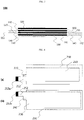
- FIG. 3 is a diagram showing an electrode assembly including electrode plates with electrode plate extensions coupled to each other according to an embodiment of the present disclosure.
- the negative electrode plate 150 and the positive electrode plate 110 are alternately stacked in the order of a negative electrode plate, a separator and a positive electrode plate, and the separator 130 is interposed between the negative electrode plate 150 and the positive electrode plate 110.
- This may be understood from the structure where a separator and a negative electrode plate are stacked and the structure where a separator and a positive electrode plate are stacked as shown in FIGS. 2a and 2b .
- the positive electrode tab 112 and the negative electrode tab 152 are formed at opposite sides of the electrode assembly 100 based on the center of the electrode assembly 100.
- the electrode plate extensions 120 and 140 are respectively formed at the positive electrode plate 110 and the negative electrode plate 150, the electrode plate extensions 120 of the positive electrode plates, which face each other, are coupled to each other, and the electrode plate extensions 140 of the negative electrode plates, which face each other, are coupled to each other.
- the electrode plate extensions 120 and 140 formed respectively at the positive electrode plate 110 and the negative electrode plate 150 have the same shape. In some cases, the electrode plate extensions 120, 140 may be shaped to coincide with each other when they are bent by pressure for mutual coupling.
- FIG. 4 is a diagram showing (a) a structure of a positive electrode plate and a separator and (b) a structure of a negative electrode plate and a separator, where electrode plate extensions are formed according to another embodiment of the present disclosure.
- the positive electrode tab 212 formed at the positive electrode plate 210 and the negative electrode tab 252 formed at the negative electrode plate 250 are formed to protrude outwards from the same side of the electrode assembly, and electrode lead coupling portions 212a, 252a are formed at ends of the positive electrode tab 212 and the negative electrode tab 252, respectively, for coupling with electrode leads (not shown).
- the electrode plate extensions 220, 240 of the positive electrode plate and the negative electrode plate are also formed to protrude outwards from the same side of the electrode assembly.
- the electrode plate extensions 220, 240 of the positive electrode plate and the negative electrode plate are positioned between the positive electrode tab 212 and the negative electrode tab 252, and the electrode plate extensions 220 of the positive electrode plate and the electrode plate extensions 240 of the negative electrode plate, which are stacked to face each other in a vertical direction, are coupled to each other by means of welding.
- the electrode plate extensions 220, 240 of the electrode plates may also be formed so that the electrode plate extensions 220 of the positive electrode plate face themselves and the electrode plate extensions 240 of the negative electrode plate face themselves.
- the electrode plate extension 220 of the positive electrode plate and the electrode plate extension 240 of the negative electrode plate are spaced apart from each other by a predetermined distance in order to prevent an electrical short, and accordingly the electrode plate extension 220 of the negative electrode plate and the electrode plate extension 240 are formed not to be in contact with each other.
Landscapes
- Chemical & Material Sciences (AREA)
- Chemical Kinetics & Catalysis (AREA)
- Electrochemistry (AREA)
- General Chemical & Material Sciences (AREA)
- Engineering & Computer Science (AREA)
- Manufacturing & Machinery (AREA)
- Materials Engineering (AREA)
- Secondary Cells (AREA)
- Connection Of Batteries Or Terminals (AREA)
Abstract
Description
- The present application claims priority to
Korean Patent Application No. 10-2016-0070419 filed on June 7, 2016 - The present disclosure relates to an electrode assembly including electrode plates with electrode plate extensions coupled to each other.
- Along with technology development and increased demands for mobile devices, there has been a rapid increase in demand for secondary batteries as energy sources. Among such secondary batteries, lithium secondary batteries, which exhibit high energy density, high operating potential, a long cycle life and a low self-discharging rate, have been commercialized and widely used.
- Secondary batteries are classified into a cylindrical or rectangular battery in which an electrode assembly is included in a cylindrical or rectangular metal can and a pouch-type battery in which an electrode assembly is included in a pouch-type case made of an aluminum laminate sheet, depending on the shape of the battery case.
- In addition, the electrode assembly included in the battery case is a power generation device capable of charging and discharging, having a laminate structure composed of a positive electrode, a separator and a negative electrode. The electrode assembly is classified into a jelly-roll electrode assembly in which a positive electrode and a negative electrode with an elongated sheet form are rolled with a separator being interposed between them, a stacked electrode assembly in which a plurality of positive and negative electrodes of a predetermined size are sequentially stacked with a separator being interposed therebetween, and a stacked-folded electrode assembly in which stacked unit cells are wound with a separating film. The electrode assembly of the stacked structure and the electrode assembly of the stacked-folded structure have a common feature in that many electrodes are stacked.
- Among them, a general structure of the stacked electrode assembly is shown in
FIG. 1 . - Referring to
FIG. 1 , a stackedelectrode assembly 10 has a laminate structure composed of a positive electrode, a separator and a negative electrode.Positive electrodes negative electrodes positive electrode tabs negative electrode tabs positive electrode tabs negative electrode tabs - Also, the plurality of
positive electrodes negative electrodes separator 32 being interposed between thepositive electrode 12 and thenegative electrode 22. In addition, thepositive electrode tabs positive electrode lead 42, and thenegative electrode tabs negative electrode lead 44. - In this case, the plurality of
positive electrode tabs positive electrode lead 42 are generally coupled to each other by welding. Thus, positive electrodetab welding portions 16 are respectively formed at thepositive electrode tabs tab welding portions 26 are respectively formed at thenegative electrode tabs - On the other hand, the positive electrode, the separator and the negative electrode are closely adhered to each other by means of lamination without performing welding separately.
- Therefore, in the conventional stacked electrode assembly, the positive electrode, the separator and the negative electrode are closely adhered to each other only through lamination, and thus when a lithium secondary battery capable of repeatedly charging and discharging is used for a long period, the thickness of the entire electrode plates varies due to contraction and expansion of the entire electrode plates during charging and discharging.
- Specifically, due to repetitive charging and discharging, a swelling phenomenon may occur among the positive electrode, the separator and the negative electrode, which are laminated.
- Accordingly, a non-contact region is formed among the positive electrode, the separator and the negative electrode, which are laminated, and a dendrite is generated in the non-contact region. Also, lithium ions are continuously deposited at the site where the dendrite is generated.
- In addition, the thickness of the positive electrode and the negative electrode is gradually increased due to the lithium ions continuously deposited at the site where the dendrite is generated, and accordingly a swelling phenomenon among the positive electrode, the separator and the negative electrode becomes worse. This may increase the thickness of the entire battery cell, and, in some cases, a short circuit occurs due to the dendrite.
- Therefore, there is a high need for a technique for preventing a swelling phenomenon among the positive electrode, the separator and the negative electrode, which are laminated, in order to prevent the risk of thickness increase and short circuit of a battery cell while ensuring stable operation of the battery cell.
- The present disclosure is designed to solve the problems of the related art and to accomplish the technical object requested from the past.
- The inventors of the present disclosure have conducted intensive research and various experiments and found that a swelling phenomenon among a positive electrode, a separator and a negative electrode, which are laminated, can be prevented if electrode plate extensions coupled to each other are formed at electrode plates of an electrode assembly, and then have reached the present disclosure.
- Therefore, an electrode assembly according to the present disclosure has a structure in which a plurality of electrode plates are stacked so that a separator is interposed between a positive electrode plate and a negative electrode plate,
wherein each of the electrode plates includes an electrode tab protruding outwards at one side thereof for coupling with an electrode lead, - wherein at least one electrode plate of the positive electrode plate and the negative electrode plate extends relatively longer than the separator at one end of the electrode plate where the electrode tab is located to form the electrode plate extension protruding out of the separator, and
wherein the electrode plate extensions of the same polarity are coupled to each other. - Accordingly, in the structure where a positive electrode plate, a separator and a negative electrode plate structure are stacked repeatedly, since the electrode plates of the same polarity are firmly coupled to each other by the electrode plate extensions, it is possible to prevent a swelling phenomenon among the positive electrode plate, the separator and the negative electrode plate even though charging and discharging are repeated.
- These electrode plate extensions may be formed in a variety of ways, for example, in a notching process of forming electrode tabs at the electrode plate.
- The electrode assembly may have a stacked-folded structure in which a plurality of unit cells including at least one positive electrode plate and at least one negative electrode plate are rolled with a separating film, or a laminated-stacked structure in which a plurality of unit cells are stacked with a separator being interposed therein.
- In an embodiment, the electrode plate extensions of the same polarity may be coupled to each other by welding, and the welding may be, for example, resistance welding, ultrasonic welding or laser welding, without being limited thereto. Therefore, any method can be used as long as the electrode plate extensions of the same polarity can be coupled.
- As described above, the electrode plate extension is formed on at least one electrode plate of the positive electrode plate and the negative electrode plate, and in detail, a positive electrode plate extension and a negative electrode plate extension may be formed at the positive electrode plate and the negative electrode plate, respectively.
- In this structure, the positive electrode tab and the negative electrode tab may be formed to protrude outwards from different sides of the electrode assembly to reduce the possibility of contact with the electrode plate extensions having an opposite polarity.
- In an embodiment, the positive electrode tab and the negative electrode tab may be formed to protrude outwards at opposite sides of the electrode assembly on the basis of the center of the electrode assembly.
- In this structure, the electrode tab may be positioned at the center of the entire electrode plate, based on the width of the electrode plate, and both sides of one end of the electrode plate where the electrode tab protrudes outwards may be classified into a first electrode plate end and a second electrode plate end on the basis of the electrode tab, and the electrode plate extension may be formed on at least one of the first electrode plate end and the second electrode plate end.
- In this regard, when the electrode plates are stacked vertically, the electrode plate extension of the positive electrode plates may be formed at the same position so that the electrode plate extensions of the positive electrode plates may be combined entirely, and the electrode plate extensions of the negative electrode plates may be formed at the same position.
- In addition, the electrode plate extensions facing each other may be formed in the same shape, but any shape may also be used as long as edges thereof may be superimposed on each other in a vertical direction, and the shape may be changed as selected by a manufacturer and according to the shape of the device.
- With respect to the location of the electrode plate extensions, assuming that a left side of the electrode tab is called a first electrode plate end, a right side of the electrode tab may be called a second electrode plate end.
- In this case, all of the positive electrode plates may be configured so that all electrode plate extensions are formed at the first electrode plate end or all electrode plate extensions are formed at the second electrode plate end.
- Since the electrode plate extensions respectively formed at the positive electrode plates may be entirely formed at the same position and superimposed, the electrode plate extensions of the positive electrode plates may be simultaneously coupled to each other by means of welding or the like.
- As described above, when the positive electrode tabs and the negative electrode tabs are located on different sides of the electrode assembly, the possibility of the electrode plate extensions formed at the positive electrode plates to be located close to the electrode plate extensions formed at the negative electrode plates may be greatly reduced.
- In an embodiment, in order to more firmly couple the positive electrode plate, the separator and the negative electrode plate, the electrode plate extensions may be formed at the first electrode plate end and the second electrode plate end, respectively.
- If the electrode plate extensions are formed at the first electrode plate end and the second electrode plate end at both sides of the electrode tab, a contact area a coupling area between the positive electrode plates may be increased, and accordingly a strong coupling force may be provided between the electrode plates.
- In another embodiment, the positive electrode tab and the negative electrode tab may be formed to protrude outwards from the same side of the electrode assembly.
- In this structure, the positive electrode tab may be formed at one portion on the same side of the electrode assembly to protrude outwards, and the negative electrode tab is formed at an opposite portion on the same side to protrude outwards.
- If the positive electrode tab and the negative electrode tab are formed in this structure, the electrode plate extensions of the positive electrode plate and the negative electrode plate may be positioned between the positive electrode tab and the negative electrode tab when being observed in a horizontal direction.
- In this case, when the electrode plates are stacked in a vertical direction, the electrode plate extensions of the positive electrode plates may be formed entirely at the same position and the plate extension positions of the negative electrode plates may be formed entirely at the same position so that the electrode plate extensions of the positive electrode plates may be coupled together.
- In addition, in order to achieve electrical insulation between the positive electrode plate and the negative electrode plate, when being observed in a horizontal direction, the electrode plate extensions of the positive electrode plates and the electrode plate extensions of the negative electrode plates may be arranged apart from each other by a predetermined distance to prevent contact between them.
- As described above, if the electrode plate extensions of the positive electrode plates and the electrode plate extensions of the negative electrode plates are spaced apart and their comers are overlapped when they are stacked in a vertical direction, the electrode plate extensions of the positive electrode plates and the electrode plate extensions of the negative electrode plates may have any shape.
- On occasions, the electrode plate extensions of the electrode plates may be subjected to an insulation treatment such as adhesion of an insulation sheet, coating of an insulating material, or the like, in order to fundamentally prevent an electrical short circuit.
- In an embodiment, a size of the electrode plate extension may be 1% to 20% of on a planar area of the electrode plate.
- If the size of the electrode plate extension is less than 1%, the welding area is not easy because an area for coupling the electrode plate extensions is narrow, which may not meet a coupling force desired by a manufacturer. On the contrary, if the size of the electrode plate extension is greater than 20%, the size of the electrode plate extension where the electrode active material is not coated is too large as compared with the area of the electrode plate, which may reduce the energy density of the battery, and the size of the electrode assembly may be increased due to the volume occupied by the electrode plate extensions.
- In an embodiment, a width of the electrode plate extension may be 100% to 500% of a width of the electrode tab.
- If the width of the electrode plate extension is less than 100% based on the width of the electrode tab, it is not easy to perform the welding operation because the area for coupling the electrode plate extensions is small, which may not meet a coupling force desired by a manufacturer. On the contrary, if the width of the electrode plate extension exceeds 500% of the width of the electrode tab, the width of the electrode plate extension may exceed the width of the electrode plate, undesirably, when the width of the electrode tab and the width of the electrode plate are taken into consideration.
- In an embodiment, a length of the electrode plate extension extending relatively longer than the separator may be 5% to 50% of a length of the electrode tab.
- If the length of the electrode plate extension is less than 5% based on the length of the electrode tab, the area for coupling the electrode plate extensions becomes inevitably narrowed, which may not meet a coupling force desired by a manufacturer. On the contrary, if the length of the electrode plate extension is formed to exceed 50% based on the length of the electrode tab, the battery energy density may be reduced since a region not contributing to the battery capacity becomes excessively large, and the size of the electrode assembly may be increased due to the volume occupied by the electrode plate extensions, undesirably.
- The present disclosure also provides a battery cell comprising the electrode assembly and a device comprising at least one battery cell as above. The structure of the battery cell and the device as well as their manufacturing methods are well known in the art and thus not described in detail here.
- As described above, the electrode assembly including the electrode plates with electrode plate extensions coupled to each other according to the present disclosure may prevent a swelling phenomenon among the positive electrode plate, the separator and the negative electrode plate even during repetitive charging and discharging processes, and thus it is possible to suppress a dendrite phenomenon and accordingly prevent the increase in thickness of the battery cell and the possibility of a short circuit.
-
-
FIG. 1 is a perspective view showing a general structure of an electrode assembly of a stacked structure. -
FIG. 2 is a diagram showing a structure composed of a positive electrode plate and a separator and a structure composed of a negative electrode plate and a separator, where electrode plate extensions are formed according to an embodiment of the present disclosure. -
FIG. 3 is a diagram showing an electrode assembly including electrode plates with electrode plate extensions coupled to each other according to an embodiment of the present disclosure. -
FIG. 4 is a diagram showing a structure of a positive electrode plate and a separator and a structure of a negative electrode plate and a separator, where electrode plate extensions are formed according to an embodiment of the present disclosure. - Hereinafter, an embodiment of the present disclosure will be described in detail with reference to the accompanying drawings, but the scope of the present disclosure is not limited thereto.
-
FIG. 2 is a diagram showing (a) a structure composed of a positive electrode plate and a separator and (b) a structure composed of a negative electrode plate and a separator, where electrode plate extensions are formed according to an embodiment of the present disclosure. - Regarding an electrode assembly in which a
positive electrode plate 110, aseparator 130 and anegative electrode plate 150 are repetitively stacked,FIG. 2a shows a structure where the singlenegative electrode plate 150 is stacked on thesingle separator 130, andFIG. 2b shows a structure where the singlepositive electrode plate 110 is stacked on thesingle separator 130. - At this time, in order to prevent an electric short circuit caused by the contact between positive electrode plates and negative electrode plates, which are repetitively stacked, the size of the
separator 130 is generally greater than the size of thepositive electrode plate 110 and thenegative electrode plate 150. - Referring to
FIG. 2 , apositive electrode tab 112 and anegative electrode tab 152 are respectively formed at thepositive electrode plate 110 and thenegative electrode plate 150 to protrude out of theseparator 130 for coupling with an electrode lead (not shown). - The
positive electrode tab 112 and thenegative electrode tab 152 are formed at opposite sides of theseparator 130, and an electrodelead coupling portion 112a is respectively formed at ends of thepositive electrode tab 112 and thenegative electrode tab 152 for coupling with an electrode lead (not shown). - At this time, based on the
positive electrode tab 112 protruding outwards, one end of thepositive electrode plate 110 is composed of a firstelectrode plate end 114 and a secondelectrode plate end 116.Electrode plate extensions 120 is respectively formed at the firstelectrode plate end 114 and the secondelectrode plate end 116 to extend relatively longer than theseparator 130 so as to protrude and expose out of theseparator 130. - The
electrode plate extensions 120 formed at both sides based on thepositive electrode tab 112 are coupled to electrode plate extensions (not shown) of upper and lower positive electrode plates which face each other. - Similarly, one end of the
negative electrode plate 150 is also composed of a firstelectrode plate end 154 and a secondelectrode plate end 156 on the basis of thenegative electrode tab 152 protruding outwards.Electrode plate extensions 140 are respectively formed at the firstelectrode plate end 154 and the secondelectrode plate end 156 to extend relatively longer than theseparator 130 so as to protrude and expose out of theseparator 130. - The
electrode plate extensions 140 formed at thenegative electrode plate 150 are also coupled to the electrode plate extensions of the upper and lower negative electrode plates to face each other, similar to theelectrode plate extensions 120 formed at the positive electrode plate. -
FIG. 3 is a diagram showing an electrode assembly including electrode plates with electrode plate extensions coupled to each other according to an embodiment of the present disclosure. - Referring to
FIG. 3 , thenegative electrode plate 150 and thepositive electrode plate 110 are alternately stacked in the order of a negative electrode plate, a separator and a positive electrode plate, and theseparator 130 is interposed between thenegative electrode plate 150 and thepositive electrode plate 110. This may be understood from the structure where a separator and a negative electrode plate are stacked and the structure where a separator and a positive electrode plate are stacked as shown inFIGS. 2a and 2b . - The
positive electrode tab 112 and thenegative electrode tab 152 are formed at opposite sides of theelectrode assembly 100 based on the center of theelectrode assembly 100. - As shown in
FIG. 3 , theelectrode plate extensions positive electrode plate 110 and thenegative electrode plate 150, theelectrode plate extensions 120 of the positive electrode plates, which face each other, are coupled to each other, and theelectrode plate extensions 140 of the negative electrode plates, which face each other, are coupled to each other. - The
electrode plate extensions positive electrode plate 110 and thenegative electrode plate 150 have the same shape. In some cases, theelectrode plate extensions -
FIG. 4 is a diagram showing (a) a structure of a positive electrode plate and a separator and (b) a structure of a negative electrode plate and a separator, where electrode plate extensions are formed according to another embodiment of the present disclosure. - Referring to
FIG. 4 , different from the structure composed of a separator and a negative electrode plate and the structure composed of a separator and a positive electrode plate shown inFIG. 2 , thepositive electrode tab 212 formed at thepositive electrode plate 210 and thenegative electrode tab 252 formed at thenegative electrode plate 250 are formed to protrude outwards from the same side of the electrode assembly, and electrodelead coupling portions positive electrode tab 212 and thenegative electrode tab 252, respectively, for coupling with electrode leads (not shown). - The
electrode plate extensions - Specifically, after the
electrode plates electrode plate extensions positive electrode tab 212 and thenegative electrode tab 252, and theelectrode plate extensions 220 of the positive electrode plate and theelectrode plate extensions 240 of the negative electrode plate, which are stacked to face each other in a vertical direction, are coupled to each other by means of welding. - Though not shown in
FIG. 4 , theelectrode plate extensions electrode plate extensions 220 of the positive electrode plate face themselves and theelectrode plate extensions 240 of the negative electrode plate face themselves. - At this time, the
electrode plate extension 220 of the positive electrode plate and theelectrode plate extension 240 of the negative electrode plate are spaced apart from each other by a predetermined distance in order to prevent an electrical short, and accordingly theelectrode plate extension 220 of the negative electrode plate and theelectrode plate extension 240 are formed not to be in contact with each other. - Various changes and modifications can be made based on the above disclosure within the scope of the present disclosure by those having ordinary skill in the art.
Claims (14)
- An electrode assembly in which a plurality of electrode plates are stacked so that a separator is interposed between a positive electrode plate and a negative electrode plate,
wherein each of the electrode plates includes an electrode tab protruding outwards at one side thereof for coupling with an electrode lead,
wherein at least one electrode plate of the positive electrode plate and the negative electrode plate extends relatively longer than the separator at one end of the electrode plate where the electrode tab is located to form an electrode plate extension protruding out of the separator, and
wherein the electrode plate extensions of the same polarity are coupled to each other. - The electrode assembly according to claim 1,
wherein the electrode assembly has a stacked structure in which a plurality of electrode plates are stacked sequentially. - The electrode assembly according to claim 1,
wherein the electrode assembly has a stacked-folded structure in which a plurality of unit cells including at least one positive electrode plate and at least one negative electrode plate are rolled with a separating film, or a laminated-stacked structure in which a plurality of unit cells are stacked with a separator being interposed therein. - The electrode assembly according to claim 1,
wherein the electrode plate extensions of the same polarity are coupled to each other by welding. - The electrode assembly according to claim 1,
wherein both sides of one end of the electrode plate where the electrode tab protrudes outwards are classified into a first electrode plate end and a second electrode plate end on the basis of the electrode tab, and the electrode plate extension is formed on at least one of the first electrode plate end and the second electrode plate end. - The electrode assembly according to claim 5,
wherein the electrode plate extension is formed at the first electrode plate end and the second electrode plate end, respectively. - The electrode assembly according to claim 1,
wherein a size of the electrode plate extension is 1% to 20% of a planar area of the electrode plate. - The electrode assembly according to claim 1,
wherein a width of the electrode plate extension is 100% to 500% of a width of the electrode tab. - The electrode assembly according to claim 1,
wherein a length of the electrode plate extension extending relatively longer than the separator is 5% to 50% of a length of the electrode tab. - The electrode assembly according to claim 1,
wherein a positive electrode plate extension and a negative electrode plate extension are respectively formed at the positive electrode plate and the negative electrode plate. - The electrode assembly according to claim 1,
wherein the positive electrode tab and the negative electrode tab protrude outwards at different sides of the electrode assembly. - The electrode assembly according to claim 11,
wherein the positive electrode tab and the negative electrode tab protrude outwards at opposite sides of the electrode assembly on the basis of the center of the electrode assembly. - A battery cell, comprising an electrode assembly defined in any of claims 1 to 12.
- A device, comprising at least one battery cell defined in claim 13.
Priority Applications (1)
| Application Number | Priority Date | Filing Date | Title |
|---|---|---|---|
| PL17174483T PL3255705T3 (en) | 2016-06-07 | 2017-06-06 | Electrode assembly with electrode plates with electrode plate extension |
Applications Claiming Priority (1)
| Application Number | Priority Date | Filing Date | Title |
|---|---|---|---|
| KR1020160070419A KR102125059B1 (en) | 2016-06-07 | 2016-06-07 | Electrode Assembly Comprising Electrode Plates Having Electrode Plate Extending Part |
Publications (2)
| Publication Number | Publication Date |
|---|---|
| EP3255705A1 true EP3255705A1 (en) | 2017-12-13 |
| EP3255705B1 EP3255705B1 (en) | 2018-10-17 |
Family
ID=59009628
Family Applications (1)
| Application Number | Title | Priority Date | Filing Date |
|---|---|---|---|
| EP17174483.2A Active EP3255705B1 (en) | 2016-06-07 | 2017-06-06 | Electrode assembly including electrode plates with electrode plate extensions |
Country Status (4)
| Country | Link |
|---|---|
| US (2) | US10381628B2 (en) |
| EP (1) | EP3255705B1 (en) |
| KR (1) | KR102125059B1 (en) |
| PL (1) | PL3255705T3 (en) |
Cited By (1)
| Publication number | Priority date | Publication date | Assignee | Title |
|---|---|---|---|---|
| EP4517896A3 (en) * | 2023-08-28 | 2025-05-07 | Samsung Sdi Co., Ltd. | Rechargeable battery |
Families Citing this family (6)
| Publication number | Priority date | Publication date | Assignee | Title |
|---|---|---|---|---|
| KR102384970B1 (en) * | 2018-08-13 | 2022-04-11 | 주식회사 엘지에너지솔루션 | Electrode and method for electrode manufacture for the same |
| KR102824735B1 (en) * | 2020-11-02 | 2025-06-24 | 주식회사 엘지에너지솔루션 | Electrode with Excellent Weldability Between Electrode Lead and Electrode Tabs and Method for Manufacturing Same |
| KR102851450B1 (en) * | 2020-11-26 | 2025-08-26 | 주식회사 엘지에너지솔루션 | Electrode assembly and secondary battery including the same |
| JP7726454B2 (en) * | 2022-01-04 | 2025-08-20 | エルジー エナジー ソリューション リミテッド | Electrode assembly including a negative electrode with an extension |
| JP2026504269A (en) * | 2022-12-22 | 2026-02-04 | エルジー エナジー ソリューション リミテッド | Battery cells |
| WO2025147150A1 (en) * | 2024-01-03 | 2025-07-10 | 주식회사 엘지에너지솔루션 | Anode for lithium metal battery, electrode assembly for lithium metal battery, and lithium metal battery |
Citations (4)
| Publication number | Priority date | Publication date | Assignee | Title |
|---|---|---|---|---|
| US20080070102A1 (en) * | 2004-05-31 | 2008-03-20 | Nissan Motor Co., Ltd. | Assembled Battery and Manufacturing Method Thereof |
| US20100173194A1 (en) * | 2007-07-20 | 2010-07-08 | Naoko Fujiya | Electric energy storage device and manufactruing method thereof |
| US20130266845A1 (en) * | 2012-04-04 | 2013-10-10 | Mitsubishi Heavy Industries, Ltd. | Battery |
| KR20160070419A (en) | 2014-12-10 | 2016-06-20 | 순천대학교 산학협력단 | Fabrication apparatus of metal product and method thereof |
Family Cites Families (12)
| Publication number | Priority date | Publication date | Assignee | Title |
|---|---|---|---|---|
| JPH07335246A (en) | 1994-06-03 | 1995-12-22 | Toyota Autom Loom Works Ltd | Cell and manufacture thereof |
| JP4468170B2 (en) * | 2002-07-25 | 2010-05-26 | 株式会社東芝 | Nonaqueous electrolyte secondary battery |
| KR100496303B1 (en) | 2003-05-19 | 2005-06-17 | 삼성에스디아이 주식회사 | Battery umit and lithium secondary battery applying the same |
| JP3972205B2 (en) * | 2003-11-06 | 2007-09-05 | 日本電気株式会社 | Stacked battery |
| JP5076639B2 (en) * | 2007-05-22 | 2012-11-21 | 日産自動車株式会社 | Secondary battery and vehicle equipped with the same |
| DE102007063181B4 (en) * | 2007-08-06 | 2010-12-30 | Daimler Ag | Single cell for a battery and method for its production |
| KR101254691B1 (en) * | 2010-08-17 | 2013-04-15 | 주식회사 엘지화학 | Secondary electric cell with enhanced lead structure |
| JP5656069B2 (en) * | 2010-12-13 | 2015-01-21 | ソニー株式会社 | Secondary battery, battery pack, electronic device, electric tool, electric vehicle and power storage system |
| JP5844052B2 (en) * | 2011-02-04 | 2016-01-13 | 三洋電機株式会社 | Multilayer battery and method for manufacturing the same |
| US8908522B2 (en) | 2012-04-30 | 2014-12-09 | Fujitsu Limited | Transmission rate control |
| JP6307827B2 (en) | 2013-09-30 | 2018-04-11 | 日産自動車株式会社 | Electric device manufacturing apparatus and electric device manufacturing method |
| KR20150043093A (en) | 2013-10-14 | 2015-04-22 | 주식회사 엘지화학 | Electrode lead and secondary battery comprising the same |
-
2016
- 2016-06-07 KR KR1020160070419A patent/KR102125059B1/en active Active
-
2017
- 2017-06-06 PL PL17174483T patent/PL3255705T3/en unknown
- 2017-06-06 EP EP17174483.2A patent/EP3255705B1/en active Active
- 2017-06-06 US US15/614,759 patent/US10381628B2/en not_active Ceased
-
2021
- 2021-08-10 US US17/398,678 patent/USRE50254E1/en active Active
Patent Citations (4)
| Publication number | Priority date | Publication date | Assignee | Title |
|---|---|---|---|---|
| US20080070102A1 (en) * | 2004-05-31 | 2008-03-20 | Nissan Motor Co., Ltd. | Assembled Battery and Manufacturing Method Thereof |
| US20100173194A1 (en) * | 2007-07-20 | 2010-07-08 | Naoko Fujiya | Electric energy storage device and manufactruing method thereof |
| US20130266845A1 (en) * | 2012-04-04 | 2013-10-10 | Mitsubishi Heavy Industries, Ltd. | Battery |
| KR20160070419A (en) | 2014-12-10 | 2016-06-20 | 순천대학교 산학협력단 | Fabrication apparatus of metal product and method thereof |
Cited By (1)
| Publication number | Priority date | Publication date | Assignee | Title |
|---|---|---|---|---|
| EP4517896A3 (en) * | 2023-08-28 | 2025-05-07 | Samsung Sdi Co., Ltd. | Rechargeable battery |
Also Published As
| Publication number | Publication date |
|---|---|
| KR102125059B1 (en) | 2020-06-19 |
| US20170352858A1 (en) | 2017-12-07 |
| USRE50254E1 (en) | 2024-12-31 |
| EP3255705B1 (en) | 2018-10-17 |
| PL3255705T3 (en) | 2019-05-31 |
| KR20170138253A (en) | 2017-12-15 |
| US10381628B2 (en) | 2019-08-13 |
Similar Documents
| Publication | Publication Date | Title |
|---|---|---|
| USRE50254E1 (en) | Electrode assembly including electrode plates with electrode plate extensions | |
| US9431679B2 (en) | Electrode assembly having stepped portion, as well as battery cell, battery pack, and device including the electrode assembly | |
| KR101379957B1 (en) | A Stepwise Electrode Assembly, and a Battery Cell, Battery Pack and Device Comprising the Same | |
| CN109792071B (en) | Method for producing an electrode stack for a battery cell and battery cell | |
| KR101792572B1 (en) | Battery Cell Having Electrode Coated with Insulating Material | |
| US9786874B2 (en) | Electrode having round corner | |
| KR102361705B1 (en) | Rechargeable battery having cover | |
| KR101637071B1 (en) | Electrode assembly having partly folded function and battery cell including the same | |
| KR102754017B1 (en) | Negative plate, electrode assembly including the same, and method of manufacturing the negative plate and electorde assembly | |
| WO2008010656A1 (en) | Electrode assembly having stable lead-tap joint and electrochemical cell containing them | |
| EP3349286B1 (en) | Electrode assembly including electrode plates with coupled additional taps formed thereon | |
| EP3614477A1 (en) | Electrode assembly and battery comprising same | |
| EP2779296A1 (en) | Secondary battery including multiple electrode assemblies | |
| KR101482385B1 (en) | Stepwise Cell Assembly | |
| KR101706319B1 (en) | Electrode Assembly and Composite Electrode Assembly of Stair-like Structure | |
| CN110192292B (en) | Battery cell and method of manufacturing battery cell | |
| KR20150040437A (en) | Jelly-Roll Type Electrode Assembly of Low Resistance And Secondary Battery Comprising the Same | |
| KR102256465B1 (en) | Electrode Assembly Folded with Zig-Zag form | |
| KR20170014476A (en) | Cylindrical Secondary Battery Having Circular Electrode | |
| JP2016085844A (en) | Power storage device | |
| KR102340101B1 (en) | Battery and method for manufcturing the same |
Legal Events
| Date | Code | Title | Description |
|---|---|---|---|
| PUAI | Public reference made under article 153(3) epc to a published international application that has entered the european phase |
Free format text: ORIGINAL CODE: 0009012 |
|
| STAA | Information on the status of an ep patent application or granted ep patent |
Free format text: STATUS: REQUEST FOR EXAMINATION WAS MADE |
|
| 17P | Request for examination filed |
Effective date: 20170606 |
|
| AK | Designated contracting states |
Kind code of ref document: A1 Designated state(s): AL AT BE BG CH CY CZ DE DK EE ES FI FR GB GR HR HU IE IS IT LI LT LU LV MC MK MT NL NO PL PT RO RS SE SI SK SM TR |
|
| AX | Request for extension of the european patent |
Extension state: BA ME |
|
| REG | Reference to a national code |
Ref country code: DE Ref legal event code: R079 Ref document number: 602017000637 Country of ref document: DE Free format text: PREVIOUS MAIN CLASS: H01M0002160000 Ipc: H01M0010052500 |
|
| GRAP | Despatch of communication of intention to grant a patent |
Free format text: ORIGINAL CODE: EPIDOSNIGR1 |
|
| STAA | Information on the status of an ep patent application or granted ep patent |
Free format text: STATUS: GRANT OF PATENT IS INTENDED |
|
| RIC1 | Information provided on ipc code assigned before grant |
Ipc: H01M 2/16 20060101ALI20180420BHEP Ipc: H01M 10/0587 20100101ALI20180420BHEP Ipc: H01M 10/04 20060101ALI20180420BHEP Ipc: H01M 10/0583 20100101ALI20180420BHEP Ipc: H01M 2/26 20060101ALI20180420BHEP Ipc: H01M 10/0585 20100101ALI20180420BHEP Ipc: H01M 10/0525 20100101AFI20180420BHEP |
|
| INTG | Intention to grant announced |
Effective date: 20180529 |
|
| GRAS | Grant fee paid |
Free format text: ORIGINAL CODE: EPIDOSNIGR3 |
|
| GRAA | (expected) grant |
Free format text: ORIGINAL CODE: 0009210 |
|
| STAA | Information on the status of an ep patent application or granted ep patent |
Free format text: STATUS: THE PATENT HAS BEEN GRANTED |
|
| AK | Designated contracting states |
Kind code of ref document: B1 Designated state(s): AL AT BE BG CH CY CZ DE DK EE ES FI FR GB GR HR HU IE IS IT LI LT LU LV MC MK MT NL NO PL PT RO RS SE SI SK SM TR |
|
| REG | Reference to a national code |
Ref country code: GB Ref legal event code: FG4D |
|
| REG | Reference to a national code |
Ref country code: CH Ref legal event code: EP |
|
| REG | Reference to a national code |
Ref country code: IE Ref legal event code: FG4D |
|
| REG | Reference to a national code |
Ref country code: AT Ref legal event code: REF Ref document number: 1055059 Country of ref document: AT Kind code of ref document: T Effective date: 20181115 |
|
| REG | Reference to a national code |
Ref country code: DE Ref legal event code: R096 Ref document number: 602017000637 Country of ref document: DE |
|
| REG | Reference to a national code |
Ref country code: NL Ref legal event code: MP Effective date: 20181017 |
|
| REG | Reference to a national code |
Ref country code: LT Ref legal event code: MG4D |
|
| REG | Reference to a national code |
Ref country code: AT Ref legal event code: MK05 Ref document number: 1055059 Country of ref document: AT Kind code of ref document: T Effective date: 20181017 |
|
| PG25 | Lapsed in a contracting state [announced via postgrant information from national office to epo] |
Ref country code: NL Free format text: LAPSE BECAUSE OF FAILURE TO SUBMIT A TRANSLATION OF THE DESCRIPTION OR TO PAY THE FEE WITHIN THE PRESCRIBED TIME-LIMIT Effective date: 20181017 |
|
| PG25 | Lapsed in a contracting state [announced via postgrant information from national office to epo] |
Ref country code: NO Free format text: LAPSE BECAUSE OF FAILURE TO SUBMIT A TRANSLATION OF THE DESCRIPTION OR TO PAY THE FEE WITHIN THE PRESCRIBED TIME-LIMIT Effective date: 20190117 Ref country code: BG Free format text: LAPSE BECAUSE OF FAILURE TO SUBMIT A TRANSLATION OF THE DESCRIPTION OR TO PAY THE FEE WITHIN THE PRESCRIBED TIME-LIMIT Effective date: 20190117 Ref country code: FI Free format text: LAPSE BECAUSE OF FAILURE TO SUBMIT A TRANSLATION OF THE DESCRIPTION OR TO PAY THE FEE WITHIN THE PRESCRIBED TIME-LIMIT Effective date: 20181017 Ref country code: LT Free format text: LAPSE BECAUSE OF FAILURE TO SUBMIT A TRANSLATION OF THE DESCRIPTION OR TO PAY THE FEE WITHIN THE PRESCRIBED TIME-LIMIT Effective date: 20181017 Ref country code: AT Free format text: LAPSE BECAUSE OF FAILURE TO SUBMIT A TRANSLATION OF THE DESCRIPTION OR TO PAY THE FEE WITHIN THE PRESCRIBED TIME-LIMIT Effective date: 20181017 Ref country code: IS Free format text: LAPSE BECAUSE OF FAILURE TO SUBMIT A TRANSLATION OF THE DESCRIPTION OR TO PAY THE FEE WITHIN THE PRESCRIBED TIME-LIMIT Effective date: 20190217 Ref country code: ES Free format text: LAPSE BECAUSE OF FAILURE TO SUBMIT A TRANSLATION OF THE DESCRIPTION OR TO PAY THE FEE WITHIN THE PRESCRIBED TIME-LIMIT Effective date: 20181017 Ref country code: LV Free format text: LAPSE BECAUSE OF FAILURE TO SUBMIT A TRANSLATION OF THE DESCRIPTION OR TO PAY THE FEE WITHIN THE PRESCRIBED TIME-LIMIT Effective date: 20181017 Ref country code: HR Free format text: LAPSE BECAUSE OF FAILURE TO SUBMIT A TRANSLATION OF THE DESCRIPTION OR TO PAY THE FEE WITHIN THE PRESCRIBED TIME-LIMIT Effective date: 20181017 |
|
| PG25 | Lapsed in a contracting state [announced via postgrant information from national office to epo] |
Ref country code: AL Free format text: LAPSE BECAUSE OF FAILURE TO SUBMIT A TRANSLATION OF THE DESCRIPTION OR TO PAY THE FEE WITHIN THE PRESCRIBED TIME-LIMIT Effective date: 20181017 Ref country code: SE Free format text: LAPSE BECAUSE OF FAILURE TO SUBMIT A TRANSLATION OF THE DESCRIPTION OR TO PAY THE FEE WITHIN THE PRESCRIBED TIME-LIMIT Effective date: 20181017 Ref country code: RS Free format text: LAPSE BECAUSE OF FAILURE TO SUBMIT A TRANSLATION OF THE DESCRIPTION OR TO PAY THE FEE WITHIN THE PRESCRIBED TIME-LIMIT Effective date: 20181017 Ref country code: GR Free format text: LAPSE BECAUSE OF FAILURE TO SUBMIT A TRANSLATION OF THE DESCRIPTION OR TO PAY THE FEE WITHIN THE PRESCRIBED TIME-LIMIT Effective date: 20190118 Ref country code: PT Free format text: LAPSE BECAUSE OF FAILURE TO SUBMIT A TRANSLATION OF THE DESCRIPTION OR TO PAY THE FEE WITHIN THE PRESCRIBED TIME-LIMIT Effective date: 20190217 |
|
| REG | Reference to a national code |
Ref country code: DE Ref legal event code: R097 Ref document number: 602017000637 Country of ref document: DE |
|
| PG25 | Lapsed in a contracting state [announced via postgrant information from national office to epo] |
Ref country code: DK Free format text: LAPSE BECAUSE OF FAILURE TO SUBMIT A TRANSLATION OF THE DESCRIPTION OR TO PAY THE FEE WITHIN THE PRESCRIBED TIME-LIMIT Effective date: 20181017 Ref country code: CZ Free format text: LAPSE BECAUSE OF FAILURE TO SUBMIT A TRANSLATION OF THE DESCRIPTION OR TO PAY THE FEE WITHIN THE PRESCRIBED TIME-LIMIT Effective date: 20181017 Ref country code: IT Free format text: LAPSE BECAUSE OF FAILURE TO SUBMIT A TRANSLATION OF THE DESCRIPTION OR TO PAY THE FEE WITHIN THE PRESCRIBED TIME-LIMIT Effective date: 20181017 |
|
| PLBE | No opposition filed within time limit |
Free format text: ORIGINAL CODE: 0009261 |
|
| STAA | Information on the status of an ep patent application or granted ep patent |
Free format text: STATUS: NO OPPOSITION FILED WITHIN TIME LIMIT |
|
| PG25 | Lapsed in a contracting state [announced via postgrant information from national office to epo] |
Ref country code: EE Free format text: LAPSE BECAUSE OF FAILURE TO SUBMIT A TRANSLATION OF THE DESCRIPTION OR TO PAY THE FEE WITHIN THE PRESCRIBED TIME-LIMIT Effective date: 20181017 Ref country code: RO Free format text: LAPSE BECAUSE OF FAILURE TO SUBMIT A TRANSLATION OF THE DESCRIPTION OR TO PAY THE FEE WITHIN THE PRESCRIBED TIME-LIMIT Effective date: 20181017 Ref country code: SM Free format text: LAPSE BECAUSE OF FAILURE TO SUBMIT A TRANSLATION OF THE DESCRIPTION OR TO PAY THE FEE WITHIN THE PRESCRIBED TIME-LIMIT Effective date: 20181017 Ref country code: SK Free format text: LAPSE BECAUSE OF FAILURE TO SUBMIT A TRANSLATION OF THE DESCRIPTION OR TO PAY THE FEE WITHIN THE PRESCRIBED TIME-LIMIT Effective date: 20181017 |
|
| 26N | No opposition filed |
Effective date: 20190718 |
|
| PG25 | Lapsed in a contracting state [announced via postgrant information from national office to epo] |
Ref country code: SI Free format text: LAPSE BECAUSE OF FAILURE TO SUBMIT A TRANSLATION OF THE DESCRIPTION OR TO PAY THE FEE WITHIN THE PRESCRIBED TIME-LIMIT Effective date: 20181017 |
|
| PG25 | Lapsed in a contracting state [announced via postgrant information from national office to epo] |
Ref country code: MC Free format text: LAPSE BECAUSE OF FAILURE TO SUBMIT A TRANSLATION OF THE DESCRIPTION OR TO PAY THE FEE WITHIN THE PRESCRIBED TIME-LIMIT Effective date: 20181017 |
|
| REG | Reference to a national code |
Ref country code: BE Ref legal event code: MM Effective date: 20190630 |
|
| PG25 | Lapsed in a contracting state [announced via postgrant information from national office to epo] |
Ref country code: TR Free format text: LAPSE BECAUSE OF FAILURE TO SUBMIT A TRANSLATION OF THE DESCRIPTION OR TO PAY THE FEE WITHIN THE PRESCRIBED TIME-LIMIT Effective date: 20181017 |
|
| PG25 | Lapsed in a contracting state [announced via postgrant information from national office to epo] |
Ref country code: IE Free format text: LAPSE BECAUSE OF NON-PAYMENT OF DUE FEES Effective date: 20190606 |
|
| PG25 | Lapsed in a contracting state [announced via postgrant information from national office to epo] |
Ref country code: BE Free format text: LAPSE BECAUSE OF NON-PAYMENT OF DUE FEES Effective date: 20190630 Ref country code: LU Free format text: LAPSE BECAUSE OF NON-PAYMENT OF DUE FEES Effective date: 20190606 |
|
| REG | Reference to a national code |
Ref country code: CH Ref legal event code: PL |
|
| PG25 | Lapsed in a contracting state [announced via postgrant information from national office to epo] |
Ref country code: LI Free format text: LAPSE BECAUSE OF NON-PAYMENT OF DUE FEES Effective date: 20200630 Ref country code: CH Free format text: LAPSE BECAUSE OF NON-PAYMENT OF DUE FEES Effective date: 20200630 |
|
| PG25 | Lapsed in a contracting state [announced via postgrant information from national office to epo] |
Ref country code: CY Free format text: LAPSE BECAUSE OF FAILURE TO SUBMIT A TRANSLATION OF THE DESCRIPTION OR TO PAY THE FEE WITHIN THE PRESCRIBED TIME-LIMIT Effective date: 20181017 |
|
| PG25 | Lapsed in a contracting state [announced via postgrant information from national office to epo] |
Ref country code: HU Free format text: LAPSE BECAUSE OF FAILURE TO SUBMIT A TRANSLATION OF THE DESCRIPTION OR TO PAY THE FEE WITHIN THE PRESCRIBED TIME-LIMIT; INVALID AB INITIO Effective date: 20170606 Ref country code: MT Free format text: LAPSE BECAUSE OF FAILURE TO SUBMIT A TRANSLATION OF THE DESCRIPTION OR TO PAY THE FEE WITHIN THE PRESCRIBED TIME-LIMIT Effective date: 20181017 |
|
| PG25 | Lapsed in a contracting state [announced via postgrant information from national office to epo] |
Ref country code: MK Free format text: LAPSE BECAUSE OF FAILURE TO SUBMIT A TRANSLATION OF THE DESCRIPTION OR TO PAY THE FEE WITHIN THE PRESCRIBED TIME-LIMIT Effective date: 20181017 |
|
| P01 | Opt-out of the competence of the unified patent court (upc) registered |
Effective date: 20230512 |
|
| REG | Reference to a national code |
Ref country code: DE Ref legal event code: R081 Ref document number: 602017000637 Country of ref document: DE Owner name: LG ENERGY SOLUTION, LTD., KR Free format text: FORMER OWNER: LG CHEM, LTD., SEOUL, KR |
|
| REG | Reference to a national code |
Ref country code: GB Ref legal event code: 732E Free format text: REGISTERED BETWEEN 20230824 AND 20230831 |
|
| PGFP | Annual fee paid to national office [announced via postgrant information from national office to epo] |
Ref country code: DE Payment date: 20250520 Year of fee payment: 9 Ref country code: PL Payment date: 20250521 Year of fee payment: 9 |
|
| PGFP | Annual fee paid to national office [announced via postgrant information from national office to epo] |
Ref country code: GB Payment date: 20250520 Year of fee payment: 9 |
|
| PGFP | Annual fee paid to national office [announced via postgrant information from national office to epo] |
Ref country code: FR Payment date: 20250521 Year of fee payment: 9 |