EP3255698A1 - Top cover of power battery and power battery - Google Patents
Top cover of power battery and power battery Download PDFInfo
- Publication number
- EP3255698A1 EP3255698A1 EP17151088.6A EP17151088A EP3255698A1 EP 3255698 A1 EP3255698 A1 EP 3255698A1 EP 17151088 A EP17151088 A EP 17151088A EP 3255698 A1 EP3255698 A1 EP 3255698A1
- Authority
- EP
- European Patent Office
- Prior art keywords
- top cover
- power battery
- cover plate
- plate
- connecting portion
- Prior art date
- Legal status (The legal status is an assumption and is not a legal conclusion. Google has not performed a legal analysis and makes no representation as to the accuracy of the status listed.)
- Granted
Links
Images


Classifications
-
- H—ELECTRICITY
- H01—ELECTRIC ELEMENTS
- H01M—PROCESSES OR MEANS, e.g. BATTERIES, FOR THE DIRECT CONVERSION OF CHEMICAL ENERGY INTO ELECTRICAL ENERGY
- H01M50/00—Constructional details or processes of manufacture of the non-active parts of electrochemical cells other than fuel cells, e.g. hybrid cells
- H01M50/10—Primary casings; Jackets or wrappings
- H01M50/147—Lids or covers
-
- H—ELECTRICITY
- H01—ELECTRIC ELEMENTS
- H01M—PROCESSES OR MEANS, e.g. BATTERIES, FOR THE DIRECT CONVERSION OF CHEMICAL ENERGY INTO ELECTRICAL ENERGY
- H01M50/00—Constructional details or processes of manufacture of the non-active parts of electrochemical cells other than fuel cells, e.g. hybrid cells
- H01M50/50—Current conducting connections for cells or batteries
- H01M50/572—Means for preventing undesired use or discharge
- H01M50/574—Devices or arrangements for the interruption of current
- H01M50/578—Devices or arrangements for the interruption of current in response to pressure
-
- H—ELECTRICITY
- H01—ELECTRIC ELEMENTS
- H01M—PROCESSES OR MEANS, e.g. BATTERIES, FOR THE DIRECT CONVERSION OF CHEMICAL ENERGY INTO ELECTRICAL ENERGY
- H01M50/00—Constructional details or processes of manufacture of the non-active parts of electrochemical cells other than fuel cells, e.g. hybrid cells
- H01M50/50—Current conducting connections for cells or batteries
- H01M50/572—Means for preventing undesired use or discharge
- H01M50/584—Means for preventing undesired use or discharge for preventing incorrect connections inside or outside the batteries
- H01M50/59—Means for preventing undesired use or discharge for preventing incorrect connections inside or outside the batteries characterised by the protection means
- H01M50/593—Spacers; Insulating plates
-
- H—ELECTRICITY
- H01—ELECTRIC ELEMENTS
- H01M—PROCESSES OR MEANS, e.g. BATTERIES, FOR THE DIRECT CONVERSION OF CHEMICAL ENERGY INTO ELECTRICAL ENERGY
- H01M2200/00—Safety devices for primary or secondary batteries
- H01M2200/20—Pressure-sensitive devices
-
- H—ELECTRICITY
- H01—ELECTRIC ELEMENTS
- H01M—PROCESSES OR MEANS, e.g. BATTERIES, FOR THE DIRECT CONVERSION OF CHEMICAL ENERGY INTO ELECTRICAL ENERGY
- H01M2220/00—Batteries for particular applications
- H01M2220/20—Batteries in motive systems, e.g. vehicle, ship, plane
-
- Y—GENERAL TAGGING OF NEW TECHNOLOGICAL DEVELOPMENTS; GENERAL TAGGING OF CROSS-SECTIONAL TECHNOLOGIES SPANNING OVER SEVERAL SECTIONS OF THE IPC; TECHNICAL SUBJECTS COVERED BY FORMER USPC CROSS-REFERENCE ART COLLECTIONS [XRACs] AND DIGESTS
- Y02—TECHNOLOGIES OR APPLICATIONS FOR MITIGATION OR ADAPTATION AGAINST CLIMATE CHANGE
- Y02E—REDUCTION OF GREENHOUSE GAS [GHG] EMISSIONS, RELATED TO ENERGY GENERATION, TRANSMISSION OR DISTRIBUTION
- Y02E60/00—Enabling technologies; Technologies with a potential or indirect contribution to GHG emissions mitigation
- Y02E60/10—Energy storage using batteries
Definitions
- the present application relates to the field of energy storage device and, particularly, relates to a top cover of a power battery and the power battery.
- the positive electrode main circuit includes an air pressure deformable plate and a conductive plate which is integrated with the CID as a whole.
- the periphery of the conductive plate is connected with an electrode tab of bare cell through welding, the CID portion of the conductive plate is connected with the deformable plate as a whole through welding, and the deformable plate is connected with a positive electrode column through welding so as to conduct a current to a positive electrode terminal.
- the main circuit can be cut off after the CID is torn.
- the conductive plate is integrated with the CID as a whole, and is then fixed with the deformable plate through welding, and the bottom periphery of the conductive plate needs to be welded with the electrode tab of bare cell.
- the conductive plate integrated with the CID as a whole is connected with the deformable plate at the top, and is connected with the electrode tab of bare cell at the bottom, if there is no other component for auxiliary fixing, it is easy to be broken and lose efficacy during the process of normal assembling and using, or the conductive plate is conductively connected with the deformable plate or the top cover plate after being deformed.
- the present application provides a top cover of a power battery and a power battery, which can solve the above problems.
- a first aspect of the present application provides a top cover of a power battery including a top cover plate, a first electrode unit and a second electrode unit, the first electrode unit includes a deformable plate, an insulation piece and a conductive plate, the top cover plate is provided with a deformable plate connecting hole, the deformable plate seals the deformable plate connecting hole, the insulation piece is located underneath the top cover plate, the insulation piece is connected with the top cover plate, the conductive plate is insulated from and fixed with the top cover plate through the insulation piece and is electrically connected with the deformable plate, the deformable plate turns and cuts off an electrical connection with the conductive plate when an internal pressure of the power battery exceeds a reference pressure.
- the insulation piece is adhered and fixed with the top cover plate.
- the first electrode unit further includes a connecting piece
- the insulation piece is provided with a connecting piece fitting portion and a conductive plate connecting portion
- the connecting piece is connected with the top cover plate, and is cooperatively connected with the connecting piece fitting portion, so as to fix the insulation piece, the conductive plate is fixed through the conductive plate connecting portion.
- the connecting piece includes a top cover plate connecting portion and an insulation piece connecting portion, the top cover plate connecting portion is connected with the top cover plate, the insulation piece connecting portion is cooperatively connected with the connecting piece fitting portion.
- the connecting piece fitting portion is an inserting slot
- the inserting slot extends along a thickness direction perpendicular to the top cover plate
- the insulation piece connecting portion is an inserting block
- the inserting block is inserted into the inserting slot.
- a plurality of connecting piece fitting portions are defined, which surround an edge of the insulation piece or are symmetrically provided thereat, each of the inserting slot is cooperated with at least one connecting piece.
- the insulation piece connecting portion is provided at a side of the top cover plate connecting portion.
- the insulation piece is further provided with an assembling hole
- the connecting piece fitting portion is provided on an inner wall of the assembling hole
- the connecting piece is arranged in the assembling hole.
- the insulation piece connecting portion is provided at an edge of the top cover plate connecting portion.
- the connecting piece fitting portion is symmetrically provided at both sides of the assembling hole
- the insulation piece connecting portion is symmetrically provided at both sides of the top cover plate connecting portion.
- the connecting piece fitting portion is provided to surround the assembling hole
- the insulation piece connecting portion is provided to surround the top cover plate connecting portion.
- an upper surface of the top cover plate connecting portion is aligned with an upper surface of the insulation piece, the top cover plate connecting portion is welded with a lower surface of the top cover plate.
- the top cover plate is provided with a fixing hole
- the connecting piece is cooperatively fixed and connected with the fixing hole.
- the fixing hole is a though hole.
- the fixing hole is a ladder hole with a top diameter larger than a bottom diameter, the connecting piece is clamped and cooperated with the fixing hole.
- the fixing hole is a blind hole provided at a lower surface of the top cover plate.
- the fixing hole is welded and fixed with the connecting piece.
- the conductive plate connecting portion is a clamping slot, an edge of the conductive plate is clamped in the clamping slot.
- a second aspect of the present application provides a power battery, including the above top cover plate of the power battery.
- the power battery provided by the present application can effectively prevent breaking, losing efficacy or deformation of the conductive plate during using process by adopting an insulation piece to firmly fix the conductive plate on the top cover plate.
- an embodiment of the present application provides a top cover of a power battery, including a top cover plate 10, a first electrode unit 20 and a second electrode unit 30.
- the second electrode unit 30 is electrically insulated from the top cover plate 10.
- the first electrode unit 20 includes an insulation piece 200, a conductive plate 202, and a deformable plate 204.
- a deformable plate connecting hole 100 is provided on the top cover plate 10, the deformable plate 204 seals and fixes the deformable plate connecting hole 100, the insulation piece 200 is located underneath the top cover plate 10, the conductive plate 202 is integrated with a CID, and is electrically connected with the deformable plate 204, the electrical connection manner is that the middle portion of the deformable plate 204 is fixedly connected with the CID on the conductive plate 202 through welding or other manners.
- the deformable plate 204 can turn and separate from electrical connection status with the conductive plate 202 when the pressure in the interior of the power battery exceeds a reference pressure.
- the deformable plate 204 seals the deformable plate connecting hole 100, the edge of the deformable plate 204 can be welded at the top or bottom of the deformable plate connecting hole 100 (as shown in FIG. 1 ), as long as the deformable plate connecting hole 100 can be sealed.
- the deformable plate can also be integrated with the top cover plate as a whole, that is, the top cover plate punches a deformable plate at the deformable plate connecting hole, the deformable plate can be located at the top or bottom of the deformable plate connecting hole 100.
- the conductive plate 202 is fixed through the insulation piece 200, then the insulation piece 200 is fixed with the top cover plate 10.
- the insulation piece 200 can be adhered and thus fixed with the top cover plate 10 directly (referring to FIG. 2 ).
- the insulation piece 200 in the present embodiment is provided with a connecting piece fitting portion 200a and a conductive plate connecting portion 200b, and is provided with a connecting piece 206.
- the connecting piece 206 is connected with the top cover plate 10, and is cooperatively connected with the connecting piece fitting portion 200a, so as to fix the insulation piece 200, the conductive plate 202 is fixed through the conductive plate connecting portion 200b.
- the connecting piece 206 itself can be firmly fixed on the top cover plate 10 through the clamping or welding manner and the like, at the same time, the connecting piece 206 firmly fixes the insulation piece 200 through the cooperation connection with the connecting piece fitting portion 200a. At last, the conductive plate 202 is connected and fixed with the insulation piece 200, thereby achieving the auxiliary firmly fixing of the conductive plate 202.
- the connecting piece 206 can include two portions, that is, a top cover plate connecting portion 206a and an insulation piece connecting portion 206b.
- the top cover plate connecting portion 206a and the insulation piece connecting portion 206b can be fixedly connected or integrated as a whole.
- the top cover plate connecting portion 206a is configured to be connected with the top cover plate 10.
- the top cover plate connecting portion 206a can be directly welded with the lower surface of the top cover plate 10, thus can avoid changing the structure of the top cover plate 10.
- the upper surface of the top cover plate connecting portion 206a can be arranged to be a plane shape, and fitted with the lower surface of the top cover plate 10, thereby improving the connection strength effectively through the manner of enlarging the connecting area.
- the upper surface of the top cover plate connecting portion 206a is preferred to be aligned with the upper surface of the insulation piece 200.
- the top cover plate 10 can be connected with the top cover plate connecting portion 206a adopting other manners.
- a fixing hole 102 can be provided on the top cover plate 10, the top cover plate connecting portion 206a is cooperatively fixed and connected with the fixing hole 102.
- the fixing hole 102 can adopt a through hole (referring to FIG. 6 and FIG. 9 ), and can also adopt a blind hole (referring to FIG. 7 ) provided at the lower surface of the top cover plate 10. Adopting a through hole can facilitate welding of the top cover plate 10 with the top cover plate connecting portion 206a on the top of the top cover plate 10, welding slag and welding line will not be left in the interior of the power battery, and therefore bringing less influence to the performance of the power battery.
- the through hole can be provided to be a ladder hole with a top diameter larger than a bottom diameter, the top cover plate connecting portion 206a and the fixing hole 102 are clamped, which can also improve sealing performance of the fixing hole, meanwhile preventing the top cover plate connecting portion 206a from falling into the interior of the power battery.
- Adopting a blind hole can generate a larger pushing force to the top cover plate connecting portion 206a by the top cover plate 10 while connecting the insulation piece connecting portion 206b with the connecting piece fitting portion 200a, so as to achieve a firmer connection between the insulation piece connecting portion 206b and the connecting piece fitting portion 200a.
- the insulation piece connecting portion 206b can be provided at the periphery or two symmetrical sides of the insulation piece 200 (referring to FIG. 8 ).
- a preferred manner is to adopt an inserting slot, the inserting slot extends along the thickness direction perpendicular to the top cover plate 10, the insulation piece connecting portion 206b is an inserting block, the inserting block is inserted into the inserting slot, so as to limit movement of the inserting block in multiple directions, and thereby improving the fixing effect.
- a plate with a uniform thickness can be adopted and then bended into portions with different heights, so as to form the top cover plate connecting portion 206a and the insulation piece connecting portion 206b, respectively.
- each inserting slot is cooperated with at least one connecting piece 206.
- the insulation piece 200 can be surrounded in the middle by arranging multiple connecting pieces 206 at the periphery thereof, by adopting these connecting pieces 206 and the interaction of the inserting slots, movement of the insulation piece 200 can be limited in all directions, thereby improving stability.
- the insulation piece connecting portion 206b on the connecting piece 206 is preferred to be provided at a side of the top cover plate connecting portion 206a, the top cover plate connecting portion 206a being located at the outside position after the insulation piece connecting portion 206b is inserted into the inserting slot.
- the inserting slot can also be provided in the interior of the insulation piece 200, the insulation piece connecting portion 206b can be inserted from an end of the inserting slot, and then fixed.
- the inserting slot can be provided by adopting another manner.
- An assembling hole 200c is provided on the insulation piece 200, the inserting slot is provided on the inner wall of the assembling hole 200c.
- the connecting piece 206 is located in the assembling hole 200c, which performs better invisibility, at the same time, more internal space of the power battery can be saved.
- the conductive plate connecting portion 200b cannot be connected with the assembling hole 200c, so as to prevent the conductive plate 202 from being electrically connected with the top cover plate 10 through the connecting piece 206.
- the insulation piece connecting portion 206b is provided at the edge of the top cover plate connecting portion 206a so as to be inserted into the inserting slot.
- the inserting slot can be provided only at two symmetrical sides of the assembling hole 200c (referring to FIG. 10 and FIG. 11 ), and can also be provided to surround the periphery of the assembling hole 200c (referring to FIG. 12 and FIG. 13 ), the position of the insulation piece connecting portion 206b with respect to the top cover plate connecting portion 206a is corresponding to the position of the inserting slot, so as to be inserted into the inserting slot.
- the connecting piece fitting portion 200a can also adopt a through hole, the through hole can be clamped after the top cover plate connecting portion 206a passes through the connecting piece fitting portion 200a, so as to prevent the insulation piece 200 from moving.
- the connecting piece fitting portion 200a can adopt a ladder hole with a top diameter smaller than a bottom diameter, thus, the portion of the top cover plate connecting portion 206a which is used to clamp the connecting piece fitting portion 200a can be located in the interior of the insulation piece 200, which will not protrude from the insulation piece 200 to occupy more space of the power battery.
- the top cover plate connecting portion 206a can adopt a rivet, after the rivet passes through the connecting piece fitting portion 200a, the head of the rivet will be riveted to be flat through a riveting manner, so as to clamp the connecting piece fitting portion 200a.
- the conductive plate 202 is insulated form and fixed with the top cover plate 10 through the conductive plate connecting portion 200b.
- the conductive plate connecting portion 200b can be provided as a clamping slot, the edge of the conductive plate 202 can be clamped in the clamping slot.
- the conductive plate 202 can be firmly fixed on the top cover plate 10 through the insulation piece, so as to prevent the conductive plate 202 from breaking and losing efficacy caused by self-displacement during normal assembling and using process.
- the present embodiment also provides a power battery, by adopting the top cover of the power battery, malfunctions caused by breaking, losing efficacy or deformation of the conductive plate during using process can be effectively prevented, at the same time, a larger interior space can be provided.
Landscapes
- Chemical & Material Sciences (AREA)
- Chemical Kinetics & Catalysis (AREA)
- Electrochemistry (AREA)
- General Chemical & Material Sciences (AREA)
- Connection Of Batteries Or Terminals (AREA)
- Sealing Battery Cases Or Jackets (AREA)
Abstract
Description
- The present application relates to the field of energy storage device and, particularly, relates to a top cover of a power battery and the power battery.
- In order to solve the over-charging problem of the EV shell battery, a general solution adopted in the industry is to cut off the main circuit before the cell loses efficacy, so as to prevent the battery from being charged continuously thereby ensuring safety of the battery.
- At present, for a square shaped shell battery, a current interrupting device (CID) may be adopted. That is, the positive electrode main circuit includes an air pressure deformable plate and a conductive plate which is integrated with the CID as a whole. The periphery of the conductive plate is connected with an electrode tab of bare cell through welding, the CID portion of the conductive plate is connected with the deformable plate as a whole through welding, and the deformable plate is connected with a positive electrode column through welding so as to conduct a current to a positive electrode terminal.
- When a battery is over charged, the internal air pressure is increased, the deformable plate is turned thus tearing the CID, so that the deformable plate is cut off from the conductive plate.
- Theoretically, as long as a certain gap exists between the conductive plate and the formable plate or the positive terminal connected with the deformable plate, the main circuit can be cut off after the CID is torn. However, as mentioned above, the conductive plate is integrated with the CID as a whole, and is then fixed with the deformable plate through welding, and the bottom periphery of the conductive plate needs to be welded with the electrode tab of bare cell.
- As we known, a certain air pressure is needed to push the deformable plate to tear the CID, both the deformable plate and the CID cannot be made too strong. Relatively speaking, it is preferred to be a little bit weaker. Thus, the conductive plate integrated with the CID as a whole is connected with the deformable plate at the top, and is connected with the electrode tab of bare cell at the bottom, if there is no other component for auxiliary fixing, it is easy to be broken and lose efficacy during the process of normal assembling and using, or the conductive plate is conductively connected with the deformable plate or the top cover plate after being deformed.
- The present application provides a top cover of a power battery and a power battery, which can solve the above problems.
- A first aspect of the present application provides a top cover of a power battery including a top cover plate, a first electrode unit and a second electrode unit,
the first electrode unit includes a deformable plate, an insulation piece and a conductive plate,
the top cover plate is provided with a deformable plate connecting hole, the deformable plate seals the deformable plate connecting hole, the insulation piece is located underneath the top cover plate, the insulation piece is connected with the top cover plate, the conductive plate is insulated from and fixed with the top cover plate through the insulation piece and is electrically connected with the deformable plate,
the deformable plate turns and cuts off an electrical connection with the conductive plate when an internal pressure of the power battery exceeds a reference pressure. - Preferably, the insulation piece is adhered and fixed with the top cover plate.
- Preferably, the first electrode unit further includes a connecting piece, the insulation piece is provided with a connecting piece fitting portion and a conductive plate connecting portion, the connecting piece is connected with the top cover plate, and is cooperatively connected with the connecting piece fitting portion, so as to fix the insulation piece, the conductive plate is fixed through the conductive plate connecting portion.
- Preferably, the connecting piece includes a top cover plate connecting portion and an insulation piece connecting portion, the top cover plate connecting portion is connected with the top cover plate, the insulation piece connecting portion is cooperatively connected with the connecting piece fitting portion.
- Preferably, the connecting piece fitting portion is an inserting slot, the inserting slot extends along a thickness direction perpendicular to the top cover plate, the insulation piece connecting portion is an inserting block, the inserting block is inserted into the inserting slot.
- Preferably, a plurality of connecting piece fitting portions are defined, which surround an edge of the insulation piece or are symmetrically provided thereat, each of the inserting slot is cooperated with at least one connecting piece.
- Preferably, the insulation piece connecting portion is provided at a side of the top cover plate connecting portion.
- Preferably, the insulation piece is further provided with an assembling hole, the connecting piece fitting portion is provided on an inner wall of the assembling hole, the connecting piece is arranged in the assembling hole.
- Preferably, the insulation piece connecting portion is provided at an edge of the top cover plate connecting portion.
- Preferably, the connecting piece fitting portion is symmetrically provided at both sides of the assembling hole, the insulation piece connecting portion is symmetrically provided at both sides of the top cover plate connecting portion.
- Preferably, the connecting piece fitting portion is provided to surround the assembling hole, the insulation piece connecting portion is provided to surround the top cover plate connecting portion.
- Preferably, an upper surface of the top cover plate connecting portion is aligned with an upper surface of the insulation piece, the top cover plate connecting portion is welded with a lower surface of the top cover plate.
- Preferably, the top cover plate is provided with a fixing hole, the connecting piece is cooperatively fixed and connected with the fixing hole.
- Preferably, the fixing hole is a though hole.
- Preferably, the fixing hole is a ladder hole with a top diameter larger than a bottom diameter, the connecting piece is clamped and cooperated with the fixing hole.
- Preferably, the fixing hole is a blind hole provided at a lower surface of the top cover plate.
- Preferably, the fixing hole is welded and fixed with the connecting piece.
- Preferably, the conductive plate connecting portion is a clamping slot, an edge of the conductive plate is clamped in the clamping slot.
- A second aspect of the present application provides a power battery, including the above top cover plate of the power battery.
- The technical solution provided by the present application can reach the following beneficial effect:
- The power battery provided by the present application can effectively prevent breaking, losing efficacy or deformation of the conductive plate during using process by adopting an insulation piece to firmly fix the conductive plate on the top cover plate.
- It should be understood that, the above general description and the following detailed description are just exemplary, which cannot limit the present application.
-
-
FIG. 1 is a side sectional diagram of an integral top cover of a power battery according to an embodiment of the present application; -
FIG. 2 is a partial enlarged diagram of part A of the top cover of the power battery inFIG. 1 , of which an insulation piece is directly adhered to a top cover plate, according to an embodiment of the present application; -
FIG. 3 is an explosive view of cooperation relationship of an insulation piece with an inserting slot arranged at an edge thereof and a conductive plate as well as a connecting piece according to an embodiment of the present application; -
FIG. 4 is an assembling structural diagram ofFIG. 3 ; -
FIG. 5 is a partial enlarged diagram of part A of the top cover of the power battery inFIG. 1 , of which the assembling structure ofFIG. 4 is adopted; -
FIG. 6 is a partial enlarged diagram of part A of the top cover of the power battery inFIG. 1 , of which a top cover plate is provided with a through hole type fixing hole, according to an embodiment of the present application; -
FIG. 7 is a partial enlarged diagram of part A of the top cover of the power battery inFIG. 1 , of which a top cover plate is provided with a blind hole type fixing hole, according to an embodiment of the present application; -
FIG. 8 is a partial enlarged diagram of part A of the top cover of the power battery inFIG. 1 , of which a connecting piece is arranged at an edge thereof, according to an embodiment of the present application; -
FIG. 9 is a partial enlarged diagram of part A of the top cover of the power battery inFIG. 1 , of which a connecting piece fitting portion is a groove provided in the interior of an insulation piece, according to an embodiment of the present application; -
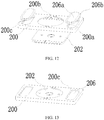
FIG. 10 is an explosive view of cooperation relationship of an insulation piece with an inserting slot provided at two symmetrical sides of an assembling hole and a conductive plate as well as a connecting piece according to an embodiment of the present application; -
FIG. 11 is an assembling structural diagram ofFIG. 10 ; -
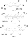
FIG. 12 is an explosive view of cooperation relationship of an insulation piece with an inserting slot provided at periphery of an assembling hole and a conductive plate as well as a connecting piece according to an embodiment of the present application; -
FIG. 13 is an assembling structural diagram ofFIG. 12 ; and -
FIG. 14 is a partial enlarged diagram of part A of the top cover of the power battery inFIG. 1 , of which the assembling structure ofFIG. 11 orFIG. 13 is adopted. -
- 10 - top cover plate;
- 100 - deformable plate connecting hole;
- 102 - fixing hole;
- 20 - first electrode unit;
- 200 - insulation piece;
- 200a - connecting piece fitting portion;
- 200b - conductive plate connecting portion;
- 200c - assembling hole;
- 202 - conductive plate;
- 204 - deformable plate;
- 206 - connecting piece;
- 206a - top cover plate connecting portion;
- 206b - insulation piece connecting portion;
- 30 - second electrode unit.
- These drawings are incorporated into the specification and constitute as a part of the specification, which show embodiments of the present application, and are used to illustrate the principle of the present application together with the specification.
- The present application will be described in further detail through specific embodiments and the accompany drawings. The "front", "back", "left", "right", "up", "down" are referring to the placing states of a top cover of a power battery and the power battery in the drawings.
- As shown in
FIG. 1 , an embodiment of the present application provides a top cover of a power battery, including atop cover plate 10, afirst electrode unit 20 and asecond electrode unit 30. Thesecond electrode unit 30 is electrically insulated from thetop cover plate 10. Thefirst electrode unit 20 includes aninsulation piece 200, aconductive plate 202, and adeformable plate 204. In the present embodiment, a deformableplate connecting hole 100 is provided on thetop cover plate 10, thedeformable plate 204 seals and fixes the deformableplate connecting hole 100, theinsulation piece 200 is located underneath thetop cover plate 10, theconductive plate 202 is integrated with a CID, and is electrically connected with thedeformable plate 204, the electrical connection manner is that the middle portion of thedeformable plate 204 is fixedly connected with the CID on theconductive plate 202 through welding or other manners. - The
deformable plate 204 can turn and separate from electrical connection status with theconductive plate 202 when the pressure in the interior of the power battery exceeds a reference pressure. - The
deformable plate 204 seals the deformableplate connecting hole 100, the edge of thedeformable plate 204 can be welded at the top or bottom of the deformable plate connecting hole 100 (as shown inFIG. 1 ), as long as the deformableplate connecting hole 100 can be sealed. Absolutely, the deformable plate can also be integrated with the top cover plate as a whole, that is, the top cover plate punches a deformable plate at the deformable plate connecting hole, the deformable plate can be located at the top or bottom of the deformableplate connecting hole 100. - In order to fix the
conductive plate 202 firmly, and prevent theconductive plate 202 from breaking, losing efficacy or deformation during normal assembling and using process, in the present embodiment, theconductive plate 202 is fixed through theinsulation piece 200, then theinsulation piece 200 is fixed with thetop cover plate 10. - Various fixing manners can be adopted between the
insulation piece 200 and thetop cover plate 10, for example, theinsulation piece 200 can be adhered and thus fixed with thetop cover plate 10 directly (referring toFIG. 2 ). - However, in order to improve the connection strength between the
insulation piece 200 and thetop cover plate 10, as shown fromFIG. 3 to FIG. 14 , theinsulation piece 200 in the present embodiment is provided with a connecting piecefitting portion 200a and a conductiveplate connecting portion 200b, and is provided with a connectingpiece 206. The connectingpiece 206 is connected with thetop cover plate 10, and is cooperatively connected with the connecting piecefitting portion 200a, so as to fix theinsulation piece 200, theconductive plate 202 is fixed through the conductiveplate connecting portion 200b. - The connecting
piece 206 itself can be firmly fixed on thetop cover plate 10 through the clamping or welding manner and the like, at the same time, the connectingpiece 206 firmly fixes theinsulation piece 200 through the cooperation connection with the connecting piecefitting portion 200a. At last, theconductive plate 202 is connected and fixed with theinsulation piece 200, thereby achieving the auxiliary firmly fixing of theconductive plate 202. - In the present embodiment, for convenient connection, the connecting
piece 206 can include two portions, that is, a top coverplate connecting portion 206a and an insulationpiece connecting portion 206b. The top coverplate connecting portion 206a and the insulationpiece connecting portion 206b can be fixedly connected or integrated as a whole. The top coverplate connecting portion 206a is configured to be connected with thetop cover plate 10. - As shown from
FIG. 3 to FIG. 5 and fromFIG. 10 to FIG. 14 , the top coverplate connecting portion 206a can be directly welded with the lower surface of thetop cover plate 10, thus can avoid changing the structure of thetop cover plate 10. In order to improve connection strength, the upper surface of the top coverplate connecting portion 206a can be arranged to be a plane shape, and fitted with the lower surface of thetop cover plate 10, thereby improving the connection strength effectively through the manner of enlarging the connecting area. In order to achieve tightly contact between theinsulation piece 200 and thetop cover plate 10, the upper surface of the top coverplate connecting portion 206a is preferred to be aligned with the upper surface of theinsulation piece 200. - In the present embodiment, the
top cover plate 10 can be connected with the top coverplate connecting portion 206a adopting other manners. Specifically, a fixinghole 102 can be provided on thetop cover plate 10, the top coverplate connecting portion 206a is cooperatively fixed and connected with the fixinghole 102. In order to improve the connection strength between them, it is preferred to adopt the welding manner for fixing. - The fixing
hole 102 can adopt a through hole (referring toFIG. 6 andFIG. 9 ), and can also adopt a blind hole (referring toFIG. 7 ) provided at the lower surface of thetop cover plate 10. Adopting a through hole can facilitate welding of thetop cover plate 10 with the top coverplate connecting portion 206a on the top of thetop cover plate 10, welding slag and welding line will not be left in the interior of the power battery, and therefore bringing less influence to the performance of the power battery. Further, the through hole can be provided to be a ladder hole with a top diameter larger than a bottom diameter, the top coverplate connecting portion 206a and the fixinghole 102 are clamped, which can also improve sealing performance of the fixing hole, meanwhile preventing the top coverplate connecting portion 206a from falling into the interior of the power battery. Adopting a blind hole can generate a larger pushing force to the top coverplate connecting portion 206a by thetop cover plate 10 while connecting the insulationpiece connecting portion 206b with the connecting piecefitting portion 200a, so as to achieve a firmer connection between the insulationpiece connecting portion 206b and the connecting piecefitting portion 200a. - As long as the connecting piece
fitting portion 200a in the present embodiment can be dragged by the insulationpiece connecting portion 206b, so as to prevent theinsulation piece 200 from falling down. For example, the insulationpiece connecting portion 206b can be provided at the periphery or two symmetrical sides of the insulation piece 200 (referring toFIG. 8 ). A preferred manner is to adopt an inserting slot, the inserting slot extends along the thickness direction perpendicular to thetop cover plate 10, the insulationpiece connecting portion 206b is an inserting block, the inserting block is inserted into the inserting slot, so as to limit movement of the inserting block in multiple directions, and thereby improving the fixing effect. When adopting the inserting slot structure, a plate with a uniform thickness can be adopted and then bended into portions with different heights, so as to form the top coverplate connecting portion 206a and the insulationpiece connecting portion 206b, respectively. - There are various manners for arranging the inserting slot, one of them is that, the inserting slots are provided at the edge of the
insulation piece 200, at this time, the number of the inserting slot is more than one, which are provided to surround at the edge of theinsulation piece 200 or symmetrically provided thereat (referring toFIGs. 3-5 ), each inserting slot is cooperated with at least one connectingpiece 206. Through this manner, theinsulation piece 200 can be surrounded in the middle by arranging multiple connectingpieces 206 at the periphery thereof, by adopting these connectingpieces 206 and the interaction of the inserting slots, movement of theinsulation piece 200 can be limited in all directions, thereby improving stability. At this time, the insulationpiece connecting portion 206b on the connectingpiece 206 is preferred to be provided at a side of the top coverplate connecting portion 206a, the top coverplate connecting portion 206a being located at the outside position after the insulationpiece connecting portion 206b is inserted into the inserting slot. - As shown in
FIG. 9 , the inserting slot can also be provided in the interior of theinsulation piece 200, the insulationpiece connecting portion 206b can be inserted from an end of the inserting slot, and then fixed. - As shown from
FIG. 10 to FIG. 14 , the inserting slot can be provided by adopting another manner. An assemblinghole 200c is provided on theinsulation piece 200, the inserting slot is provided on the inner wall of the assemblinghole 200c. Thus, the connectingpiece 206 is located in the assemblinghole 200c, which performs better invisibility, at the same time, more internal space of the power battery can be saved. However, when adopting this manner, it should be noted that the conductiveplate connecting portion 200b cannot be connected with the assemblinghole 200c, so as to prevent theconductive plate 202 from being electrically connected with thetop cover plate 10 through the connectingpiece 206. Since the connectingpiece 206 is arranged in the assemblinghole 200c, therefore, the insulationpiece connecting portion 206b is provided at the edge of the top coverplate connecting portion 206a so as to be inserted into the inserting slot. At this time, the inserting slot can be provided only at two symmetrical sides of the assemblinghole 200c (referring toFIG. 10 and FIG. 11 ), and can also be provided to surround the periphery of the assemblinghole 200c (referring toFIG. 12 and FIG. 13 ), the position of the insulationpiece connecting portion 206b with respect to the top coverplate connecting portion 206a is corresponding to the position of the inserting slot, so as to be inserted into the inserting slot. - Similarly, as shown in
FIG. 6 and FIG. 7 , in the present embodiment, the connecting piecefitting portion 200a can also adopt a through hole, the through hole can be clamped after the top coverplate connecting portion 206a passes through the connecting piecefitting portion 200a, so as to prevent theinsulation piece 200 from moving. In order to reduce the occupied internal space of the power battery, the connecting piecefitting portion 200a can adopt a ladder hole with a top diameter smaller than a bottom diameter, thus, the portion of the top coverplate connecting portion 206a which is used to clamp the connecting piecefitting portion 200a can be located in the interior of theinsulation piece 200, which will not protrude from theinsulation piece 200 to occupy more space of the power battery. In the above situation, the top coverplate connecting portion 206a can adopt a rivet, after the rivet passes through the connecting piecefitting portion 200a, the head of the rivet will be riveted to be flat through a riveting manner, so as to clamp the connecting piecefitting portion 200a. - In the present embodiment, the
conductive plate 202 is insulated form and fixed with thetop cover plate 10 through the conductiveplate connecting portion 200b. For convenient connection, the conductiveplate connecting portion 200b can be provided as a clamping slot, the edge of theconductive plate 202 can be clamped in the clamping slot. Thus, theconductive plate 202 can be firmly fixed on thetop cover plate 10 through the insulation piece, so as to prevent theconductive plate 202 from breaking and losing efficacy caused by self-displacement during normal assembling and using process. - The present embodiment also provides a power battery, by adopting the top cover of the power battery, malfunctions caused by breaking, losing efficacy or deformation of the conductive plate during using process can be effectively prevented, at the same time, a larger interior space can be provided.
- The above are just the preferred embodiments of the present application, which will not limit the present application, for those skilled in the art, the present application can have various modifications and variations. Any modifications, equivalent replacements and improvements made within the principle of the present application shall fall in the protection scope of the present application.
Claims (19)
- A top cover of a power battery, characterized in that, comprising a top cover plate, a first electrode unit and a second electrode unit,
the first electrode unit comprises a deformable plate, an insulation piece and a conductive plate,
the top cover plate is provided with a deformable plate connecting hole, the deformable plate seals the deformable plate connecting hole, the insulation piece is located underneath the top cover plate, the insulation piece is connected with the top cover plate, the conductive plate is insulated from and fixed with the top cover plate through the insulation piece and is electrically connected with the deformable plate,
the deformable plate turns and cuts off an electrical connection with the conductive plate when an internal pressure of the power battery exceeds a reference pressure. - The top cover of the power battery according to claim 1, characterized in that, the insulation piece is adhered and fixed with the top cover plate.
- The top cover of the power battery according to claim 1, characterized in that, the first electrode unit further comprises a connecting piece,
the insulation piece is provided with a connecting piece fitting portion and a conductive plate connecting portion, the connecting piece is connected with the top cover plate, and is cooperatively connected with the connecting piece fitting portion, so as to fix the insulation piece, the conductive plate is fixed through the conductive plate connecting portion. - The top cover of the power battery according to claim 3, characterized in that, the connecting piece comprises a top cover plate connecting portion and an insulation piece connecting portion,
the top cover plate connecting portion is connected with the top cover plate, the insulation piece connecting portion is cooperatively connected with the connecting piece fitting portion. - The top cover of the power battery according to claim 4, characterized in that, the connecting piece fitting portion is an inserting slot, the inserting slot extends along a thickness direction perpendicular to the top cover plate, the insulation piece connecting portion is an inserting block, the inserting block is inserted into the inserting slot.
- The top cover of the power battery according to claim 5, characterized in that, a plurality of connecting piece fitting portions are defined, which surround an edge of the insulation piece or are symmetrically provided thereat, each of the inserting slot is cooperated with at least one connecting piece.
- The top cover of the power battery according to claim 6, characterized in that, the insulation piece connecting portion is provided at a side of the top cover plate connecting portion.
- The top cover of the power battery according to claim 5, characterized in that, the insulation piece is further provided with an assembling hole, the connecting piece fitting portion is provided on an inner wall of the assembling hole, the connecting piece is arranged in the assembling hole.
- The top cover of the power battery according to claim 8, characterized in that, the insulation piece connecting portion is provided at an edge of the top cover plate connecting portion.
- The top cover of the power battery according to claim 9, characterized in that, the connecting piece fitting portion is symmetrically provided at both sides of the assembling hole, the insulation piece connecting portion is symmetrically provided at both sides of the top cover plate connecting portion.
- The top cover of the power battery according to claim 9, characterized in that, the connecting piece fitting portion is provided to surround the assembling hole, the insulation piece connecting portion is provided to surround the top cover plate connecting portion.
- The top cover of the power battery according to claim 6 or 8, characterized in that, an upper surface of the top cover plate connecting portion is aligned with an upper surface of the insulation piece, the top cover plate connecting portion is welded with a lower surface of the top cover plate.
- The top cover of the power battery according to claim 4, characterized in that, the top cover plate is provided with a fixing hole, the connecting piece is cooperatively fixed and connected with the fixing hole.
- The top cover of the power battery according to claim 13, characterized in that, the fixing hole is a through hole.
- The top cover of the power battery according to claim 14, characterized in that, the fixing hole is a ladder hole with a top diameter larger than a bottom diameter, the connecting piece is clamped and cooperated with the fixing hole.
- The top cover of the power battery according to any one of claims 13-16, characterized in that, the fixing hole is a blind hole provided at a lower surface of the top cover plate.
- The top cover of the power battery according to any one of claims 13-16, characterized in that, the fixing hole is welded and fixed with the connecting piece.
- The top cover of the power battery according to any one of claims 4-11 and 13-16, characterized in that, the conductive plate connecting portion is a clamping slot, an edge of the conductive plate is clamped in the clamping slot.
- A power battery, characterized in that, comprising the top cover plate of the power battery according to any one of claims 1-18.
Applications Claiming Priority (1)
| Application Number | Priority Date | Filing Date | Title |
|---|---|---|---|
| CN201610399622.5A CN105870366B (en) | 2016-06-07 | 2016-06-07 | Power battery top cap and power battery |
Publications (2)
| Publication Number | Publication Date |
|---|---|
| EP3255698A1 true EP3255698A1 (en) | 2017-12-13 |
| EP3255698B1 EP3255698B1 (en) | 2019-05-08 |
Family
ID=56677177
Family Applications (1)
| Application Number | Title | Priority Date | Filing Date |
|---|---|---|---|
| EP17151088.6A Active EP3255698B1 (en) | 2016-06-07 | 2017-01-11 | Top cover of power battery and power battery |
Country Status (4)
| Country | Link |
|---|---|
| US (1) | US10418619B2 (en) |
| EP (1) | EP3255698B1 (en) |
| JP (1) | JP6218900B1 (en) |
| CN (2) | CN105870366B (en) |
Families Citing this family (10)
| Publication number | Priority date | Publication date | Assignee | Title |
|---|---|---|---|---|
| CN106450136B (en) * | 2016-11-15 | 2020-02-14 | 宁德时代新能源科技股份有限公司 | Secondary battery and battery module |
| CN108232098B (en) * | 2016-12-09 | 2021-04-27 | 宁德时代新能源科技股份有限公司 | Secondary battery |
| CN109428016B (en) * | 2017-08-30 | 2021-05-18 | 宁德时代新能源科技股份有限公司 | Secondary cell's top cap subassembly and secondary cell |
| CN207818749U (en) * | 2017-12-22 | 2018-09-04 | 比亚迪股份有限公司 | Battery cover components, single cells, battery modules, power batteries and electric vehicles |
| KR20250004378A (en) | 2019-10-31 | 2025-01-07 | 컨템포러리 엠퍼렉스 테크놀로지 (홍콩) 리미티드 | Battery module, battery pack, device and failure processing method |
| CN112332036B (en) * | 2020-04-03 | 2023-04-07 | 宁德时代新能源科技股份有限公司 | Battery module, battery pack, device and failure processing method |
| CN112103411B (en) * | 2020-09-22 | 2023-04-07 | 宁德新能源科技有限公司 | Electrochemical device and electronic device |
| CN218274683U (en) * | 2022-06-08 | 2023-01-10 | 欣旺达惠州动力新能源有限公司 | Single battery and battery pack |
| CN119447735B (en) * | 2023-08-04 | 2026-01-06 | 江苏海四达电源有限公司 | Insulation protection devices and battery modules |
| CN118523019B (en) * | 2024-07-19 | 2024-10-11 | 蜂巢能源科技股份有限公司 | Battery cover plate, battery and battery pack |
Citations (4)
| Publication number | Priority date | Publication date | Assignee | Title |
|---|---|---|---|---|
| EP1921692A1 (en) * | 2006-10-19 | 2008-05-14 | Samsung SDI Co., Ltd. | Secondary battery and method of fabricating the same |
| CN201508864U (en) * | 2009-09-10 | 2010-06-16 | 比亚迪股份有限公司 | A battery cover assembly, a single battery and a battery pack |
| US20100167107A1 (en) * | 2008-12-26 | 2010-07-01 | Sang-Won Byun | Rechargeable battery |
| WO2010088332A1 (en) * | 2009-01-30 | 2010-08-05 | Boston-Power, Inc. | Modular cid assembly for a lithium ion battery |
Family Cites Families (8)
| Publication number | Priority date | Publication date | Assignee | Title |
|---|---|---|---|---|
| US6210824B1 (en) * | 1998-01-15 | 2001-04-03 | Texas Instruments Incorporated | Current interrupt apparatus for electrochemical cells |
| JP5415413B2 (en) * | 2007-06-22 | 2014-02-12 | ボストン−パワー,インコーポレイテッド | CID holder for LI ion battery |
| CN201450037U (en) * | 2009-07-24 | 2010-05-05 | 东莞新能源科技有限公司 | Explosion-proof device for lithium ion battery |
| CN202094198U (en) * | 2011-03-25 | 2011-12-28 | 捷锐思(天津)新能源科技有限公司 | Anode explosion-proof device for lithium ion power battery |
| CN202839771U (en) * | 2012-08-02 | 2013-03-27 | 宁德时代新能源科技有限公司 | Power battery safety top cover |
| CN104641492B (en) * | 2012-09-28 | 2017-08-22 | 日立汽车系统株式会社 | Rectangular secondary cell |
| CN203631651U (en) * | 2013-10-18 | 2014-06-04 | 比克国际(天津)有限公司 | Current cut-off device and aluminum-shell lithium ion battery with same |
| CN205666262U (en) * | 2016-06-07 | 2016-10-26 | 宁德时代新能源科技股份有限公司 | Power battery top cap and power battery |
-
2016
- 2016-06-07 CN CN201610399622.5A patent/CN105870366B/en active Active
- 2016-06-07 CN CN201811390110.8A patent/CN109244285B/en active Active
- 2016-08-16 JP JP2016159533A patent/JP6218900B1/en active Active
-
2017
- 2017-01-11 EP EP17151088.6A patent/EP3255698B1/en active Active
- 2017-04-12 US US15/485,775 patent/US10418619B2/en active Active
Patent Citations (4)
| Publication number | Priority date | Publication date | Assignee | Title |
|---|---|---|---|---|
| EP1921692A1 (en) * | 2006-10-19 | 2008-05-14 | Samsung SDI Co., Ltd. | Secondary battery and method of fabricating the same |
| US20100167107A1 (en) * | 2008-12-26 | 2010-07-01 | Sang-Won Byun | Rechargeable battery |
| WO2010088332A1 (en) * | 2009-01-30 | 2010-08-05 | Boston-Power, Inc. | Modular cid assembly for a lithium ion battery |
| CN201508864U (en) * | 2009-09-10 | 2010-06-16 | 比亚迪股份有限公司 | A battery cover assembly, a single battery and a battery pack |
Also Published As
| Publication number | Publication date |
|---|---|
| CN105870366B (en) | 2019-03-15 |
| CN105870366A (en) | 2016-08-17 |
| JP6218900B1 (en) | 2017-10-25 |
| JP2017220443A (en) | 2017-12-14 |
| US10418619B2 (en) | 2019-09-17 |
| CN109244285A (en) | 2019-01-18 |
| CN109244285B (en) | 2021-06-29 |
| US20170352861A1 (en) | 2017-12-07 |
| EP3255698B1 (en) | 2019-05-08 |
Similar Documents
| Publication | Publication Date | Title |
|---|---|---|
| EP3255698A1 (en) | Top cover of power battery and power battery | |
| EP2259364B1 (en) | Rechargeable battery | |
| US9105890B2 (en) | Cylindrical type secondary battery with upper and lower battery assemblies and fabrication method thereof | |
| EP3255699B1 (en) | Top cover of power battery and power battery | |
| EP3322001B1 (en) | Secondary battery and battery module | |
| EP3255696B1 (en) | Top cover of power battery and power battery | |
| JP3973164B2 (en) | Sealed prismatic battery | |
| EP3331052A1 (en) | Secondary battery | |
| EP2924763B1 (en) | Secondary battery | |
| EP2551938A1 (en) | Connection between a terminal and a cap plate of a rechargeable battery | |
| EP3454392B1 (en) | Top cover assembly of secondary battery and secondary battery | |
| KR101268332B1 (en) | Secondary battery having superior impect strength and vibration resistance | |
| KR102612060B1 (en) | Rechargeable battery having membrane | |
| CN106450475A (en) | Secondary battery and battery module | |
| JP2011222520A (en) | Secondary battery | |
| EP2845248B1 (en) | Sealed battery | |
| CN205666262U (en) | Power battery top cap and power battery | |
| KR101733741B1 (en) | Rechargeable battery having connecting member | |
| KR20160015778A (en) | A sylnder type battery having enhanced vibration resistant property | |
| KR102332443B1 (en) | Battery module | |
| CN205666260U (en) | Power battery top cap and power battery thereof | |
| JP2019046613A (en) | Power storage device | |
| KR20160015771A (en) | A sylnder type battery having enhanced vibration resistant property | |
| CN105932180A (en) | Power battery top cap and power battery |
Legal Events
| Date | Code | Title | Description |
|---|---|---|---|
| PUAI | Public reference made under article 153(3) epc to a published international application that has entered the european phase |
Free format text: ORIGINAL CODE: 0009012 |
|
| STAA | Information on the status of an ep patent application or granted ep patent |
Free format text: STATUS: REQUEST FOR EXAMINATION WAS MADE |
|
| 17P | Request for examination filed |
Effective date: 20170111 |
|
| AK | Designated contracting states |
Kind code of ref document: A1 Designated state(s): AL AT BE BG CH CY CZ DE DK EE ES FI FR GB GR HR HU IE IS IT LI LT LU LV MC MK MT NL NO PL PT RO RS SE SI SK SM TR |
|
| AX | Request for extension of the european patent |
Extension state: BA ME |
|
| RBV | Designated contracting states (corrected) |
Designated state(s): AL AT BE BG CH CY CZ DE DK EE ES FI FR GB GR HR HU IE IS IT LI LT LU LV MC MK MT NL NO PL PT RO RS SE SI SK SM TR |
|
| STAA | Information on the status of an ep patent application or granted ep patent |
Free format text: STATUS: EXAMINATION IS IN PROGRESS |
|
| 17Q | First examination report despatched |
Effective date: 20180813 |
|
| GRAP | Despatch of communication of intention to grant a patent |
Free format text: ORIGINAL CODE: EPIDOSNIGR1 |
|
| RIC1 | Information provided on ipc code assigned before grant |
Ipc: H01M 2/34 20060101ALI20181029BHEP Ipc: H01M 2/04 20060101AFI20181029BHEP Ipc: H01M 2/26 20060101ALN20181029BHEP |
|
| STAA | Information on the status of an ep patent application or granted ep patent |
Free format text: STATUS: GRANT OF PATENT IS INTENDED |
|
| INTG | Intention to grant announced |
Effective date: 20181206 |
|
| GRAS | Grant fee paid |
Free format text: ORIGINAL CODE: EPIDOSNIGR3 |
|
| GRAA | (expected) grant |
Free format text: ORIGINAL CODE: 0009210 |
|
| STAA | Information on the status of an ep patent application or granted ep patent |
Free format text: STATUS: THE PATENT HAS BEEN GRANTED |
|
| AK | Designated contracting states |
Kind code of ref document: B1 Designated state(s): AL AT BE BG CH CY CZ DE DK EE ES FI FR GB GR HR HU IE IS IT LI LT LU LV MC MK MT NL NO PL PT RO RS SE SI SK SM TR |
|
| REG | Reference to a national code |
Ref country code: GB Ref legal event code: FG4D |
|
| REG | Reference to a national code |
Ref country code: CH Ref legal event code: EP Ref country code: AT Ref legal event code: REF Ref document number: 1131625 Country of ref document: AT Kind code of ref document: T Effective date: 20190515 |
|
| REG | Reference to a national code |
Ref country code: DE Ref legal event code: R096 Ref document number: 602017003697 Country of ref document: DE Ref country code: IE Ref legal event code: FG4D |
|
| REG | Reference to a national code |
Ref country code: NL Ref legal event code: MP Effective date: 20190508 |
|
| REG | Reference to a national code |
Ref country code: LT Ref legal event code: MG4D |
|
| PG25 | Lapsed in a contracting state [announced via postgrant information from national office to epo] |
Ref country code: NO Free format text: LAPSE BECAUSE OF FAILURE TO SUBMIT A TRANSLATION OF THE DESCRIPTION OR TO PAY THE FEE WITHIN THE PRESCRIBED TIME-LIMIT Effective date: 20190808 Ref country code: LT Free format text: LAPSE BECAUSE OF FAILURE TO SUBMIT A TRANSLATION OF THE DESCRIPTION OR TO PAY THE FEE WITHIN THE PRESCRIBED TIME-LIMIT Effective date: 20190508 Ref country code: FI Free format text: LAPSE BECAUSE OF FAILURE TO SUBMIT A TRANSLATION OF THE DESCRIPTION OR TO PAY THE FEE WITHIN THE PRESCRIBED TIME-LIMIT Effective date: 20190508 Ref country code: NL Free format text: LAPSE BECAUSE OF FAILURE TO SUBMIT A TRANSLATION OF THE DESCRIPTION OR TO PAY THE FEE WITHIN THE PRESCRIBED TIME-LIMIT Effective date: 20190508 Ref country code: AL Free format text: LAPSE BECAUSE OF FAILURE TO SUBMIT A TRANSLATION OF THE DESCRIPTION OR TO PAY THE FEE WITHIN THE PRESCRIBED TIME-LIMIT Effective date: 20190508 Ref country code: PT Free format text: LAPSE BECAUSE OF FAILURE TO SUBMIT A TRANSLATION OF THE DESCRIPTION OR TO PAY THE FEE WITHIN THE PRESCRIBED TIME-LIMIT Effective date: 20190908 Ref country code: ES Free format text: LAPSE BECAUSE OF FAILURE TO SUBMIT A TRANSLATION OF THE DESCRIPTION OR TO PAY THE FEE WITHIN THE PRESCRIBED TIME-LIMIT Effective date: 20190508 Ref country code: SE Free format text: LAPSE BECAUSE OF FAILURE TO SUBMIT A TRANSLATION OF THE DESCRIPTION OR TO PAY THE FEE WITHIN THE PRESCRIBED TIME-LIMIT Effective date: 20190508 Ref country code: HR Free format text: LAPSE BECAUSE OF FAILURE TO SUBMIT A TRANSLATION OF THE DESCRIPTION OR TO PAY THE FEE WITHIN THE PRESCRIBED TIME-LIMIT Effective date: 20190508 |
|
| PG25 | Lapsed in a contracting state [announced via postgrant information from national office to epo] |
Ref country code: GR Free format text: LAPSE BECAUSE OF FAILURE TO SUBMIT A TRANSLATION OF THE DESCRIPTION OR TO PAY THE FEE WITHIN THE PRESCRIBED TIME-LIMIT Effective date: 20190809 Ref country code: RS Free format text: LAPSE BECAUSE OF FAILURE TO SUBMIT A TRANSLATION OF THE DESCRIPTION OR TO PAY THE FEE WITHIN THE PRESCRIBED TIME-LIMIT Effective date: 20190508 Ref country code: LV Free format text: LAPSE BECAUSE OF FAILURE TO SUBMIT A TRANSLATION OF THE DESCRIPTION OR TO PAY THE FEE WITHIN THE PRESCRIBED TIME-LIMIT Effective date: 20190508 Ref country code: BG Free format text: LAPSE BECAUSE OF FAILURE TO SUBMIT A TRANSLATION OF THE DESCRIPTION OR TO PAY THE FEE WITHIN THE PRESCRIBED TIME-LIMIT Effective date: 20190808 |
|
| REG | Reference to a national code |
Ref country code: AT Ref legal event code: MK05 Ref document number: 1131625 Country of ref document: AT Kind code of ref document: T Effective date: 20190508 |
|
| PG25 | Lapsed in a contracting state [announced via postgrant information from national office to epo] |
Ref country code: SK Free format text: LAPSE BECAUSE OF FAILURE TO SUBMIT A TRANSLATION OF THE DESCRIPTION OR TO PAY THE FEE WITHIN THE PRESCRIBED TIME-LIMIT Effective date: 20190508 Ref country code: EE Free format text: LAPSE BECAUSE OF FAILURE TO SUBMIT A TRANSLATION OF THE DESCRIPTION OR TO PAY THE FEE WITHIN THE PRESCRIBED TIME-LIMIT Effective date: 20190508 Ref country code: RO Free format text: LAPSE BECAUSE OF FAILURE TO SUBMIT A TRANSLATION OF THE DESCRIPTION OR TO PAY THE FEE WITHIN THE PRESCRIBED TIME-LIMIT Effective date: 20190508 Ref country code: CZ Free format text: LAPSE BECAUSE OF FAILURE TO SUBMIT A TRANSLATION OF THE DESCRIPTION OR TO PAY THE FEE WITHIN THE PRESCRIBED TIME-LIMIT Effective date: 20190508 Ref country code: AT Free format text: LAPSE BECAUSE OF FAILURE TO SUBMIT A TRANSLATION OF THE DESCRIPTION OR TO PAY THE FEE WITHIN THE PRESCRIBED TIME-LIMIT Effective date: 20190508 Ref country code: DK Free format text: LAPSE BECAUSE OF FAILURE TO SUBMIT A TRANSLATION OF THE DESCRIPTION OR TO PAY THE FEE WITHIN THE PRESCRIBED TIME-LIMIT Effective date: 20190508 |
|
| REG | Reference to a national code |
Ref country code: DE Ref legal event code: R097 Ref document number: 602017003697 Country of ref document: DE |
|
| PG25 | Lapsed in a contracting state [announced via postgrant information from national office to epo] |
Ref country code: SM Free format text: LAPSE BECAUSE OF FAILURE TO SUBMIT A TRANSLATION OF THE DESCRIPTION OR TO PAY THE FEE WITHIN THE PRESCRIBED TIME-LIMIT Effective date: 20190508 Ref country code: IT Free format text: LAPSE BECAUSE OF FAILURE TO SUBMIT A TRANSLATION OF THE DESCRIPTION OR TO PAY THE FEE WITHIN THE PRESCRIBED TIME-LIMIT Effective date: 20190508 |
|
| PLBE | No opposition filed within time limit |
Free format text: ORIGINAL CODE: 0009261 |
|
| STAA | Information on the status of an ep patent application or granted ep patent |
Free format text: STATUS: NO OPPOSITION FILED WITHIN TIME LIMIT |
|
| PG25 | Lapsed in a contracting state [announced via postgrant information from national office to epo] |
Ref country code: TR Free format text: LAPSE BECAUSE OF FAILURE TO SUBMIT A TRANSLATION OF THE DESCRIPTION OR TO PAY THE FEE WITHIN THE PRESCRIBED TIME-LIMIT Effective date: 20190508 |
|
| 26N | No opposition filed |
Effective date: 20200211 |
|
| PG25 | Lapsed in a contracting state [announced via postgrant information from national office to epo] |
Ref country code: PL Free format text: LAPSE BECAUSE OF FAILURE TO SUBMIT A TRANSLATION OF THE DESCRIPTION OR TO PAY THE FEE WITHIN THE PRESCRIBED TIME-LIMIT Effective date: 20190508 |
|
| PG25 | Lapsed in a contracting state [announced via postgrant information from national office to epo] |
Ref country code: SI Free format text: LAPSE BECAUSE OF FAILURE TO SUBMIT A TRANSLATION OF THE DESCRIPTION OR TO PAY THE FEE WITHIN THE PRESCRIBED TIME-LIMIT Effective date: 20190508 |
|
| PG25 | Lapsed in a contracting state [announced via postgrant information from national office to epo] |
Ref country code: MC Free format text: LAPSE BECAUSE OF FAILURE TO SUBMIT A TRANSLATION OF THE DESCRIPTION OR TO PAY THE FEE WITHIN THE PRESCRIBED TIME-LIMIT Effective date: 20190508 |
|
| REG | Reference to a national code |
Ref country code: CH Ref legal event code: PL |
|
| REG | Reference to a national code |
Ref country code: BE Ref legal event code: MM Effective date: 20200131 |
|
| PG25 | Lapsed in a contracting state [announced via postgrant information from national office to epo] |
Ref country code: LU Free format text: LAPSE BECAUSE OF NON-PAYMENT OF DUE FEES Effective date: 20200111 |
|
| REG | Reference to a national code |
Ref country code: DE Ref legal event code: R079 Ref document number: 602017003697 Country of ref document: DE Free format text: PREVIOUS MAIN CLASS: H01M0002040000 Ipc: H01M0050147000 |
|
| PG25 | Lapsed in a contracting state [announced via postgrant information from national office to epo] |
Ref country code: CH Free format text: LAPSE BECAUSE OF NON-PAYMENT OF DUE FEES Effective date: 20200131 Ref country code: BE Free format text: LAPSE BECAUSE OF NON-PAYMENT OF DUE FEES Effective date: 20200131 Ref country code: LI Free format text: LAPSE BECAUSE OF NON-PAYMENT OF DUE FEES Effective date: 20200131 |
|
| PG25 | Lapsed in a contracting state [announced via postgrant information from national office to epo] |
Ref country code: IE Free format text: LAPSE BECAUSE OF NON-PAYMENT OF DUE FEES Effective date: 20200111 |
|
| PG25 | Lapsed in a contracting state [announced via postgrant information from national office to epo] |
Ref country code: MT Free format text: LAPSE BECAUSE OF FAILURE TO SUBMIT A TRANSLATION OF THE DESCRIPTION OR TO PAY THE FEE WITHIN THE PRESCRIBED TIME-LIMIT Effective date: 20190508 Ref country code: CY Free format text: LAPSE BECAUSE OF FAILURE TO SUBMIT A TRANSLATION OF THE DESCRIPTION OR TO PAY THE FEE WITHIN THE PRESCRIBED TIME-LIMIT Effective date: 20190508 |
|
| PG25 | Lapsed in a contracting state [announced via postgrant information from national office to epo] |
Ref country code: MK Free format text: LAPSE BECAUSE OF FAILURE TO SUBMIT A TRANSLATION OF THE DESCRIPTION OR TO PAY THE FEE WITHIN THE PRESCRIBED TIME-LIMIT Effective date: 20190508 Ref country code: IS Free format text: LAPSE BECAUSE OF FAILURE TO SUBMIT A TRANSLATION OF THE DESCRIPTION OR TO PAY THE FEE WITHIN THE PRESCRIBED TIME-LIMIT Effective date: 20190908 |
|
| P01 | Opt-out of the competence of the unified patent court (upc) registered |
Effective date: 20230516 |
|
| REG | Reference to a national code |
Ref country code: DE Ref legal event code: R082 Ref document number: 602017003697 Country of ref document: DE Ref country code: DE Ref legal event code: R081 Ref document number: 602017003697 Country of ref document: DE Owner name: CONTEMPORARY AMPEREX TECHNOLOGY (HONG KONG) LI, HK Free format text: FORMER OWNER: CONTEMPORARY AMPEREX TECHNOLOGY CO., LTD., NINGDE CITY, FUJIAN, CN |
|
| REG | Reference to a national code |
Ref country code: GB Ref legal event code: 732E Free format text: REGISTERED BETWEEN 20240815 AND 20240821 |
|
| PGFP | Annual fee paid to national office [announced via postgrant information from national office to epo] |
Ref country code: GB Payment date: 20251120 Year of fee payment: 10 |
|
| PGFP | Annual fee paid to national office [announced via postgrant information from national office to epo] |
Ref country code: FR Payment date: 20251124 Year of fee payment: 10 |
|
| PGFP | Annual fee paid to national office [announced via postgrant information from national office to epo] |
Ref country code: DE Payment date: 20251119 Year of fee payment: 10 |