EP3255697A1 - Top cover of power battery and power battery - Google Patents
Top cover of power battery and power battery Download PDFInfo
- Publication number
- EP3255697A1 EP3255697A1 EP17151004.3A EP17151004A EP3255697A1 EP 3255697 A1 EP3255697 A1 EP 3255697A1 EP 17151004 A EP17151004 A EP 17151004A EP 3255697 A1 EP3255697 A1 EP 3255697A1
- Authority
- EP
- European Patent Office
- Prior art keywords
- top cover
- power battery
- plate
- deformable
- connecting portion
- Prior art date
- Legal status (The legal status is an assumption and is not a legal conclusion. Google has not performed a legal analysis and makes no representation as to the accuracy of the status listed.)
- Granted
Links
Images


Classifications
-
- H—ELECTRICITY
- H01—ELECTRIC ELEMENTS
- H01M—PROCESSES OR MEANS, e.g. BATTERIES, FOR THE DIRECT CONVERSION OF CHEMICAL ENERGY INTO ELECTRICAL ENERGY
- H01M10/00—Secondary cells; Manufacture thereof
- H01M10/05—Accumulators with non-aqueous electrolyte
- H01M10/052—Li-accumulators
- H01M10/0525—Rocking-chair batteries, i.e. batteries with lithium insertion or intercalation in both electrodes; Lithium-ion batteries
-
- H—ELECTRICITY
- H01—ELECTRIC ELEMENTS
- H01M—PROCESSES OR MEANS, e.g. BATTERIES, FOR THE DIRECT CONVERSION OF CHEMICAL ENERGY INTO ELECTRICAL ENERGY
- H01M50/00—Constructional details or processes of manufacture of the non-active parts of electrochemical cells other than fuel cells, e.g. hybrid cells
- H01M50/10—Primary casings; Jackets or wrappings
- H01M50/147—Lids or covers
- H01M50/148—Lids or covers characterised by their shape
- H01M50/15—Lids or covers characterised by their shape for prismatic or rectangular cells
-
- H—ELECTRICITY
- H01—ELECTRIC ELEMENTS
- H01M—PROCESSES OR MEANS, e.g. BATTERIES, FOR THE DIRECT CONVERSION OF CHEMICAL ENERGY INTO ELECTRICAL ENERGY
- H01M50/00—Constructional details or processes of manufacture of the non-active parts of electrochemical cells other than fuel cells, e.g. hybrid cells
- H01M50/50—Current conducting connections for cells or batteries
- H01M50/528—Fixed electrical connections, i.e. not intended for disconnection
-
- H—ELECTRICITY
- H01—ELECTRIC ELEMENTS
- H01M—PROCESSES OR MEANS, e.g. BATTERIES, FOR THE DIRECT CONVERSION OF CHEMICAL ENERGY INTO ELECTRICAL ENERGY
- H01M50/00—Constructional details or processes of manufacture of the non-active parts of electrochemical cells other than fuel cells, e.g. hybrid cells
- H01M50/50—Current conducting connections for cells or batteries
- H01M50/572—Means for preventing undesired use or discharge
- H01M50/574—Devices or arrangements for the interruption of current
- H01M50/578—Devices or arrangements for the interruption of current in response to pressure
-
- H—ELECTRICITY
- H01—ELECTRIC ELEMENTS
- H01M—PROCESSES OR MEANS, e.g. BATTERIES, FOR THE DIRECT CONVERSION OF CHEMICAL ENERGY INTO ELECTRICAL ENERGY
- H01M50/00—Constructional details or processes of manufacture of the non-active parts of electrochemical cells other than fuel cells, e.g. hybrid cells
- H01M50/50—Current conducting connections for cells or batteries
- H01M50/572—Means for preventing undesired use or discharge
- H01M50/584—Means for preventing undesired use or discharge for preventing incorrect connections inside or outside the batteries
- H01M50/59—Means for preventing undesired use or discharge for preventing incorrect connections inside or outside the batteries characterised by the protection means
- H01M50/593—Spacers; Insulating plates
-
- H—ELECTRICITY
- H01—ELECTRIC ELEMENTS
- H01M—PROCESSES OR MEANS, e.g. BATTERIES, FOR THE DIRECT CONVERSION OF CHEMICAL ENERGY INTO ELECTRICAL ENERGY
- H01M2200/00—Safety devices for primary or secondary batteries
- H01M2200/20—Pressure-sensitive devices
-
- H—ELECTRICITY
- H01—ELECTRIC ELEMENTS
- H01M—PROCESSES OR MEANS, e.g. BATTERIES, FOR THE DIRECT CONVERSION OF CHEMICAL ENERGY INTO ELECTRICAL ENERGY
- H01M2220/00—Batteries for particular applications
- H01M2220/20—Batteries in motive systems, e.g. vehicle, ship, plane
-
- Y—GENERAL TAGGING OF NEW TECHNOLOGICAL DEVELOPMENTS; GENERAL TAGGING OF CROSS-SECTIONAL TECHNOLOGIES SPANNING OVER SEVERAL SECTIONS OF THE IPC; TECHNICAL SUBJECTS COVERED BY FORMER USPC CROSS-REFERENCE ART COLLECTIONS [XRACs] AND DIGESTS
- Y02—TECHNOLOGIES OR APPLICATIONS FOR MITIGATION OR ADAPTATION AGAINST CLIMATE CHANGE
- Y02E—REDUCTION OF GREENHOUSE GAS [GHG] EMISSIONS, RELATED TO ENERGY GENERATION, TRANSMISSION OR DISTRIBUTION
- Y02E60/00—Enabling technologies; Technologies with a potential or indirect contribution to GHG emissions mitigation
- Y02E60/10—Energy storage using batteries
Definitions
- the present application relates to the field of Li-ion battery production technologies and, particularly, relates to a top cover of a power battery and the power battery
- the battery in the prior art generally has two circuit breaking manners, that is, passive circuit breaking and active circuit breaking.
- the active circuit breaking manner generally provides a deformable plate and a conductive plate at the bottom of a positive electrode terminal. When a current is normally flowing, the current passes through the conductive plate and the deformable plate, and then arrives at the electrode terminal. When the battery is over charged, and generates air in the interior, the deformable plate turns and breaks the connection with the conductive plate, so as to cut off the main circuit, so that the battery is no longer charged, thereby guaranteeing safety of the cell.
- the conductive plate is connected with the deformable plate at the top, and is connected with the naked cell electrode tab at the bottom, if there is no other component for auxiliary fixing, it is easy to be broken and loses efficacy during the process of normal assembling and using, or the conductive plate is conductively connected with the deformable plate or the top cover plate after being deformed.
- the present application provides a top cover of a power battery and the power battery, which can firmly fixed a conductive plate without occupying too much interior space of the power battery.
- the present application provides a top cover of a power battery, including:
- the insulation piece accommodating portion is a through hole with a top diameter larger than a bottom diameter.
- the insulation piece accommodating portion is a blind hole with a top diameter larger than a bottom diameter.
- the insulation piece accommodating portion is an embedded groove.
- the blind hole is sunken at a lower surface of the top cover plate, or the blind hole is protruded from a lower surface of the top cover plate.
- the embedded groove is sunken at a lower surface of the top cover plate, or the embedded groove is protruded from a lower surface of the top cover plate.
- the top cover plate connecting portion is a connecting column
- the connecting column extends into the insulation piece accommodating portion, and is fixed with the insulation piece accommodating portion through hot melting.
- the top cover plate connecting portion is a clamping connection structure, the clamping connection structure is clamped with the insulation piece accommodating portion.
- multiple insulation piece accommodating portions are defined, which are arranged around the deformable plate connecting hole, the number of the top cover plate connecting portion is the same as the number of the insulation piece accommodating portion, and the top cover plate connecting portion corresponds to the insulation piece accommodating portion respectively.
- the conductive plate connecting portion comprises a plurality of independent parts, each of the independent part is provided with at least one top cover plate connecting portion.
- an assembling hole is provided on the conductive plate connecting portion, the assembling hole is opposite to the deformable plate connecting hole, the conductive plate is fixed in the assembling hole.
- the conductive plate connecting portion is further provided with a circle of blocking ring, a hole diameter of the assembling hole is larger than the deformable plate connecting hole, the blocking ring is arranged around an inner wall of a top of the assembling hole, and covers the deformable plate connecting hole.
- a circle of clamping slot is provided at a bottom of the conductive plate connecting portion, an edge of the conductive plate is clamped in the clamping slot.
- a circle of recess is provided at an edge of a bottom of the deformable plate connecting hole, an edge of the deformable plate is connected and sealed with the recess.
- the conductive plate comprises a fixing portion and a connecting portion, the fixing portion is fixed with the conductive plate connecting portion, the fixing portion is connected with the connecting portion through a weak strength area, a ventilating hole is provided on the fixing portion,
- the deformable plate comprises a connecting head, a deformable portion and a ring-shaped connecting portion
- the deformable portion is of a sheet shaped structure with a ring surface
- the connecting head is located at the middle of the deformable portion
- the ring-shaped connecting portion surrounds an outer edge of the deformable portion
- a lower surface of the connecting head is connected with an upper surface of the connecting portion
- the ring-shaped connecting portion is connected with the deformable plate connecting hole.
- the deformable plate further comprises a connecting bump, the connecting bump is protruded from the lower surface of the connecting head, the conductive plate further comprises a connecting hole, the connecting hole is provided on the connecting portion, the connecting bump is embedded into the connecting hole.
- a second aspect of the present application provides a power battery, including the above top cover of the power battery.
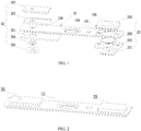
- an embodiment of the present application provides a top cover of a power battery, including a top cover plate 10, a first electrode unit 20 and a second electrode unit 30.
- the top cover plate 10 is a main structure of the top cover, which needs to be made adopting conductive materials, such as an aluminum sheet.
- An electrode terminal penetrating hole 100 and a deformable plate connecting hole 101 are provided on the top cover plate 10.
- the first electrode unit 20 and the second electrode unit 30 are respectively two output poles of the power battery, each output pole is electrically connected with an electrode tab of a naked cell respectively.
- the first electrode unit 20 can be regarded as the positive pole of the power battery
- the second electrode unit 30 can be regarded as the negative pole of the power battery.
- the first electrode unit 20 of the present embodiment includes a deformable plate 200, a conductive plate 201, a first insulation piece 202 and a top cover connecting block 203.
- the deformable plate 200 includes a connecting head 200a, a deformable portion 200b and a ring-shaped connecting portion 200c.
- the deformable portion 200b is of a sheet shaped structure with a ring surface
- the connecting head 200a is located at the middle portion of the deformable portion 200b
- the ring-shaped connecting portion 200c surrounds the outer edge of the deformable portion 200b.
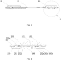
- the deformable plate 200 is connected and sealed with the deformable plate connecting hole 101 through the ring-shaped connecting portion 200c.
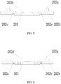
- the deformable plate 200 is connected and sealed with the deformable plate connecting hole 101, the ring-shaped connecting portion 200c can be welded at the top or the bottom of the deformable plate connecting hole 101 (as shown in FIG. 3 ).
- the deformable plate 200 After being connected like this, the deformable plate 200 will seal the deformable plate connecting hole 101 directly, with no need of arranging a sealing piece.
- a circle of recess 102 is provided at the edge of the bottom portion of the deformable plate connecting hole 101, the ring-shaped connecting portion 200c is located in the recess 102, and can be clamped by the recess 102, and then sealed with the recess 102, so that the connection strength can be improved effectively.
- the deformable plate can also be formed with the top cover plate as a whole, that is, the top cover plate punches a deformable plate at the deformable plate connecting hole, the deformable plate can be located at the top or the bottom of the deformable plate connecting hole 101.
- the conductive plate 201 includes a fixing portion 201a, a connecting portion 201b and a weak strength area 201c, the fixing portion 201a is connected with the connecting portion 201b through the weak strength area 201c.
- the fixing portion 201a is configured to be electrically connected with an electrode tab and, at the same time, also configured to achieve the effect of position fixing, therefore, the fixing portion can be appropriately made thicker, so as to increase the strength.
- the thickness of the connecting portion 201b can be reduced appropriately, so as to facilitate separating from the fixing portion 201a.
- a fixing hole 201d can be provided at the middle portion of the fixing portion 201a, the thinner connecting portion 201b only covers the top end of the fixing hole 201d, the weak strength area 201c is arranged around the connecting portion 201b. Furthermore, the whole conductive plate 201 can firstly be processed to be formed as a whole, and then scribing a circle nick at an appropriate position as the weak strength area 201c.
- the conductive plate 201 is located underneath the deformable plate 200, and fixed with the first insulation piece 202 through the fixing portion 201a, and the first insulation piece 202 is also fixed with the top cover plate 10.
- an insulation piece accommodating portion 103 is provided on the top cover plate 10, the connection between the first insulation piece 202 and the top cover plate 10 as well as the conductive plate 201 is extremely important, which plays a significant role to the stability of the conductive plate 201.
- the first insulation piece 202 includes a top cover plate connecting portion 202a and a conductive plate connecting portion 202b, the top cover plate connecting portion 202a can be fixed with the connecting portion 202b of the conductive plate or formed as a whole, the top cover plate connecting portion 202a can be fixed in the insulation piece accommodating portion 103.
- the insulation piece accommodating portion 103 and the top cover plate connecting portion 202a can adopt multiply fixing structures.
- the insulation piece accommodating portion 103 can be of a through hole structure with a top diameter larger than a bottom diameter, such as a ladder hole, for this structure, the top cover plate connecting portion 202a can adopt that a connecting column (referring to FIG. 5 ) penetrates through the ladder hole so that the head portion of the connecting column clamps the ladder hole (referring to FIG. 4 ) through a hot-melting manner.
- the top cover plate connecting portion 202a can also adopt a clamping connection structure (referring to FIG.
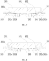
- the insulation piece accommodating portion 103 can also adopt a blind-hole structure (referring to FIG. 7 ) or an embedded groove structure (referring to FIG. 8 ).
- the top cover plate connecting portion 202a still can adopt a clamping connection structure or a hot-melting structure.
- the top cover plate connecting portion 202a cannot be inserted from the bottom of the through hole and hot-melted at the top of the through hole just like the through hole connection.
- another manner can be considered, as shown in FIG. 7 , a part of plastic material can be inserted into the blind hole and clamped through the hot-melting manner firstly, so as to form the top cover plate connecting portion 202a, and then the main structure of the first insulation piece 202 will be connected with the top cover plate connecting portion 202a through hot-melting, adhering or other manners.
- an end or two ends of the embedded groove can be designed to be open, and then insert the top cover plate connecting portion 202a through an opening end of the embedded groove, so as to form a clamping connection.
- the embedded groove and the blind hole can be sunken at the lower surface of the top cover plate 10 (referring to FIG. 7 ), and can also be protruded at the lower surface of the top cover plate 10. Even when required, the through hole can also be provided as such.
- multiple insulation piece accommodating portions 103 can be arranged around the deformable plate connecting hole 101, at this time, the number of the top cover plate connecting portion 202a is the same as the number of the insulation piece accommodating portion 103, and the top cover plate connecting portion 202a corresponds to the insulation piece accommodating portion 103 respectively.
- the acting force can be dispersed, so as to make the connection of the first insulation piece 202 firmer.
- the conductive plate 201 is insulated and fixed with the top cover plate 10 through the conductive plate connecting portion 202b.
- a clamping slot 202c can be provided at the bottom of the conductive plate connecting portion 202b, the edge of the fixing portion 201a of the conductive plate 201 can be clamped in the clamping slot 202c.
- the conductive plate 201 can be firmly fixed on the top cover plate 10 through the first insulation piece, so as to prevent the conductive plate 201 from breaking and losing efficacy caused by self-displacement during normal assembling and using process.
- the conductive plate connecting portion 202b can be constituted of several independent parts, each independent part is provided with at least one top cover plate connecting portion 202a.
- the top cover plate connecting portion 202a is fixed at the bottom of the top cover plate 10 around the deformable plate connecting hole 101, then the fixing portion 201a of the conductive plate 201 is respectively connected with each independent part.
- the conductive plate connecting portion 202b can also be an integral whole, which facilitates assembling. Referring to FIG. 4 , an assembling hole 202d is provided on the whole structure of the conductive plate connecting portion 202b, after the first insulation piece 202 is fixed with the top cover plate 10, the assembling hole 202d is opposite to the deformable plate connecting hole 101, the fixing portion 201a is fixed in the assembling hole 202d.
- the present embodiment also provides a circle of blocking ring 202e on the conductive plate connecting portion 202b, in order to fix a larger conductive plate 201, the hole diameter of the assembling hole 202d can be made larger, for example, larger than the deformable plate connecting hole 101, and the blocking ring 202e is arranged around the inner wall of the top of the assembling hole 202d, and covers the recess 102.
- the conductive plate 201 is fixed with the portion of the assembling hole 202e located under the blocking ring 202e, and the blocking ring 202e becomes the interlayer between the conductive plate 201 and the top cover plate 10, when assembling, as long as the conductive plate 201 abuts the blocking ring 202e firmly, the assembling firmness and good insulation can be ensured.
- the material of the first insulation piece 202 can be selected from insulation plastics such as PP, PE, PFA, PPS, PA and the like.
- the lower surface of the connecting head 200a is fixedly connected with the upper surface of the connecting portion 201b.
- the deformable plate 200 in the present embodiment further includes a connecting bump 200d, the connecting bump 200d is protruded from the lower surface of the connecting head 200a, at the same time, the conductive plate 201 also includes a connecting hole 201e, the connecting hole 201e is provided on the connecting portion, the connecting bump 200d can be embedded into the connecting hole 201e, thus the connecting head 200a and the connecting bump 200d can be connected with the conductive plate 201 from different directions at the same time.
- a circuit can be transmitted through the fixing portion 201a of the conductive plate 201 of the first electrode unit 20 to the connecting portion 201b, and then transmitted onto the top cover plate 10 through the connecting head 200a, the deformable portion 200b and the ring-shaped connecting portion 200c of the deformable plate 200.
- the first electrode unit 20 of the present embodiment fixes the top cover connecting block 203 on the upper surface of the top cover plate 10, so as to be used as a connecting terminal.
- a sunken assembling platform 104 can be formed on the upper surface of the top cover plate 10 in advance, the shape of the assembling platform 104 needs to be matched with the top cover connecting block 203, and then the top cover connecting block 203 will be embedded into the assembling platform 104 through a welding manner and the like, thus not only the connecting strength between the top cover connecting block 203 and the top cover plate 10 can be improved, a better sealing effect can also be achieved, so as to avoid leaking of the electrolyte.
- the insulation piece accommodating portion 103 can be arranged in the range of the assembling platform 104, which can be kept parallel and level to the bottom of the assembling platform 104 after the top cover plate connecting portion 202a is fixed with the insulation piece accommodating portion 103, and then the top cover connecting block 203 will cover the insulation piece accommodating portion 103 when being embedded into the assembling platform 104.
- the first insulation piece 202 and the conductive plate 201 will not block off the bottom of the deformable portion 200b, but leave a passage communicating with the interior of the power battery.
- This passage can be achieved by providing a ventilating hole 201f on the fixing portion 201a.
- the second electrode unit 30 in the present embodiment includes an electrode terminal 300, a second insulation piece 301, a third insulation piece 302 and an electrode terminal connecting block 303.
- the electrode terminal 300 is located in the electrode terminal penetrating hole 100, at the same time, the second insulation piece 301 is located between the electrode terminal 300 and the top cover plate 10, so that the electrode terminal 300 is insulated from the top cover plate 10.
- the middle portion of the electrode terminal 300 is located in the electrode terminal penetrating hole 100, the top end and the bottom end thereof are both located at the outside of the electrode terminal penetrating hole 100, in addition, in order to increase the connecting area, the bottom of the electrode terminal 300 will be increased transversely to form a platform.
- the second insulation piece 301 is not only located between the electrode terminal 300 and the electrode terminal penetrating hole 100, but also extended to the lower surface of the top cover plate 10, so as to ensure that there is no contact between the platform of the electrode terminal 300 and top cover plate 10.
- the electrode terminal connecting block 303 is located at the upper surface of the top cover plate 10, which has the same function as the top cover connecting portion 203, that is, being used as the connecting terminal as well, so as to overcome the difficultly of directly connecting with the electrode terminal 300. Since the top cover plate 10 is already electrically connected with the positive electrode of the naked cell, therefore, the electrode terminal connecting block 303 needs to be insulated from the top cover plate 10 through the third insulation piece 302, so as to prevent short circuit.
- a sealing ring 304 and other sealing structures can be further arranged, which will not be repeated here.
- the deformable plate 200 can be made with a diameter of 22mm, the diameter of the deformable area 200b is 20mm.
- the current flowing area comparing to the prior structure is significantly improved.
- the deformable plate connecting hole 101 can achieve the effect of avoiding the deformable plate 200, the deformable plate 200 can directly turn in the deformable plate connecting hole 101 of the top cover plate 10, therefore, the thickness of the deformable plate 200 will not occupy the interior space of the power battery, thereby substantially reducing the total thickness.
- the thickness of the first electrode unit 20 is almost the same as the thickness of the second electrode unit 30, which balances the distribution of the thickness of the top cover, the wasted space becomes smaller when connecting with the naked cell, thereby also taking full advantage of space. Furthermore, the conductive plate 201 can be fixed firmly by the first insulation piece 202.
Landscapes
- Chemical & Material Sciences (AREA)
- Chemical Kinetics & Catalysis (AREA)
- Electrochemistry (AREA)
- General Chemical & Material Sciences (AREA)
- Engineering & Computer Science (AREA)
- Materials Engineering (AREA)
- Manufacturing & Machinery (AREA)
- Connection Of Batteries Or Terminals (AREA)
- Sealing Battery Cases Or Jackets (AREA)
Abstract
Description
- The present application relates to the field of Li-ion battery production technologies and, particularly, relates to a top cover of a power battery and the power battery
- In the situation that a battery or a module is over charged, when excessive heat is generated or the pressure in the interior of a power battery increases due to resolving of the electrolyte, the battery will burn or explode. Therefore, before the battery is out of control, a structure is desired to cut off the main circuit of the battery, and prevent the battery from being charged continuously.
- The battery in the prior art generally has two circuit breaking manners, that is, passive circuit breaking and active circuit breaking. The active circuit breaking manner generally provides a deformable plate and a conductive plate at the bottom of a positive electrode terminal. When a current is normally flowing, the current passes through the conductive plate and the deformable plate, and then arrives at the electrode terminal. When the battery is over charged, and generates air in the interior, the deformable plate turns and breaks the connection with the conductive plate, so as to cut off the main circuit, so that the battery is no longer charged, thereby guaranteeing safety of the cell.
- However, in such connection structure, since the deformable plate and the conductive plate are both arranged underneath the positive electrode terminal, therefore, the thickness of the top cover of the power battery at the positive electrode is increased, which further increases the volume of the power battery, wasting too much space, especially the space between a corresponding negative electrode terminal and a naked cell.
- As we known, a certain air pressure is needed to push the deformable plate to tear the conductive plate, both the deformable plate and the conductive plate cannot be made too strong. Relatively speaking, it is preferred to be a little bit weaker. The conductive plate is connected with the deformable plate at the top, and is connected with the naked cell electrode tab at the bottom, if there is no other component for auxiliary fixing, it is easy to be broken and loses efficacy during the process of normal assembling and using, or the conductive plate is conductively connected with the deformable plate or the top cover plate after being deformed.
- In view of the above, it is necessary to design a conductive plate fixing structure, which achieves the effect of fixing and insulation and, at the same time, increases the utilization space of the interior of the battery as much as possible.
- The present application provides a top cover of a power battery and the power battery, which can firmly fixed a conductive plate without occupying too much interior space of the power battery.
- The present application provides a top cover of a power battery, including:
- a top cover plate, a first electrode unit and a second electrode unit,
- the top cover plate is provided with a deformable plate connecting hole and an insulation piece accommodating portion, the first electrode unit comprises a deformable plate, a conductive plate and a first insulation piece,
- the deformable plate seals the deformable plate connecting hole, the conductive plate is located underneath the deformable plate, and is electrically connected with the deformable plate, the first insulation piece comprises a top cover plate connecting portion and a conductive plate connecting portion, the top cover plate connecting portion extends into the insulation piece accommodating portion and is fixed with the insulation piece accommodating portion, the conductive plate is insulated and fixed with the top cover plate through the conductive plate connecting portion,
- the deformable plate deforms and is insulated from the conductive plate when a pressure in an interior of the power battery exceeds a reference pressure.
- Preferably, the insulation piece accommodating portion is a through hole with a top diameter larger than a bottom diameter.
- Preferably, the insulation piece accommodating portion is a blind hole with a top diameter larger than a bottom diameter.
- Preferably, the insulation piece accommodating portion is an embedded groove.
- Preferably, the blind hole is sunken at a lower surface of the top cover plate, or the blind hole is protruded from a lower surface of the top cover plate.
- Preferably, the embedded groove is sunken at a lower surface of the top cover plate, or the embedded groove is protruded from a lower surface of the top cover plate.
- Preferably, the top cover plate connecting portion is a connecting column, the connecting column extends into the insulation piece accommodating portion, and is fixed with the insulation piece accommodating portion through hot melting.
- Preferably, the top cover plate connecting portion is a clamping connection structure, the clamping connection structure is clamped with the insulation piece accommodating portion.
- Preferably, multiple insulation piece accommodating portions are defined, which are arranged around the deformable plate connecting hole, the number of the top cover plate connecting portion is the same as the number of the insulation piece accommodating portion, and the top cover plate connecting portion corresponds to the insulation piece accommodating portion respectively.
- Preferably, the conductive plate connecting portion comprises a plurality of independent parts, each of the independent part is provided with at least one top cover plate connecting portion.
- Preferably, an assembling hole is provided on the conductive plate connecting portion, the assembling hole is opposite to the deformable plate connecting hole, the conductive plate is fixed in the assembling hole.
- Preferably, the conductive plate connecting portion is further provided with a circle of blocking ring, a hole diameter of the assembling hole is larger than the deformable plate connecting hole, the blocking ring is arranged around an inner wall of a top of the assembling hole, and covers the deformable plate connecting hole.
- Preferably, a circle of clamping slot is provided at a bottom of the conductive plate connecting portion, an edge of the conductive plate is clamped in the clamping slot.
- Preferably, a circle of recess is provided at an edge of a bottom of the deformable plate connecting hole, an edge of the deformable plate is connected and sealed with the recess.
- Preferably, the conductive plate comprises a fixing portion and a connecting portion, the fixing portion is fixed with the conductive plate connecting portion, the fixing portion is connected with the connecting portion through a weak strength area, a ventilating hole is provided on the fixing portion,
- the deformable plate comprises a connecting head, a deformable portion and a ring-shaped connecting portion, the deformable portion is of a sheet shaped structure with a ring surface, the connecting head is located at the middle of the deformable portion, the ring-shaped connecting portion surrounds an outer edge of the deformable portion,
a lower surface of the connecting head is connected with an upper surface of the connecting portion, the ring-shaped connecting portion is connected with the deformable plate connecting hole. - Preferably, the deformable plate further comprises a connecting bump, the connecting bump is protruded from the lower surface of the connecting head, the conductive plate further comprises a connecting hole, the connecting hole is provided on the connecting portion, the connecting bump is embedded into the connecting hole.
- A second aspect of the present application provides a power battery, including the above top cover of the power battery.
- The technical solution provided by the present application can achieve the following beneficial effect:
- The top cover of the power battery and the power battery provided by the present application can make the top cover plate firmly fix with the insulation sheet through improving the structures thereof, so as to prevent the conductive plate from breaking and losing efficacy caused by self-displacement, furthermore, such connection structure occupies a smaller interior space of the power battery.
- It should be understood that, the above general description and the following detailed description are just exemplary, which cannot limit the present application.
-
-
FIG. 1 is an explosive view of a top cover of a power battery according to an embodiment of the present application; -
FIG. 2 is an assembling structural schematic diagram of a top cover of a power battery according to an embodiment of the present application; -
FIG. 3 is a side sectional view ofFIG. 2 ; -
FIG. 4 is a partial enlarged structural schematic diagram of part A of the top cover of the power battery inFIG. 3 , of which an insulation piece connecting portion adopts a ladder hole according to an embodiment of the present application; -
FIG. 5 is a structural schematic diagram of cooperation between a first insulation piece adopting a connection column and a conductive plate according to an embodiment of the present application; -
FIG. 6 is a structural schematic diagram of cooperation between a first insulation piece adopting a clamping connection structure and a conductive plate according to an embodiment of the present application; -
FIG. 7 is a partial enlarged structural schematic diagram of part A of the top cover of the power battery inFIG. 3 , of which an insulation piece connecting portion adopts a blind hole according to an embodiment of the present application; -
FIG. 8 is a partial enlarged structural schematic diagram of part A of the top cover of the power battery inFIG. 3 , of which an insulation piece connecting portion adopts an embedded groove according to an embodiment of the present application; -
FIG. 9 is a structural schematic diagram of cooperation between a first insulation piece being divided into two independent parts and a conductive plate according to an embodiment of the present application; -
FIG. 10 is a schematic diagram of a top view structure of a deformable plate according to an embodiment of the present application; -
FIG. 11 is a side sectional view ofFIG. 10 ; -
FIG. 12 is a schematic diagram of a top view structure of a conductive plate according to an embodiment of the present application; -
FIG. 13 is a side sectional view ofFIG. 12 ; -
FIG. 14 is a partial enlarged structural schematic diagram of part B inFIG. 13 ; and -
FIG. 15 is a side sectional view of a PHEV2-model power battery assembled with a top cover of a power battery according to an embodiment of the present application. -
- 10
- - top cover plate;
- 100
- - electrode terminal penetrating hole;
- 101
- - deformable plate connecting hole;
- 102
- - recess;
- 103
- - insulation piece accommodating portion;
- 104
- - assembling platform;
- 20
- - first electrode unit;
- 200
- - deformable plate;
- 200a
- - connecting head;
- 200b
- - deformable portion;
- 200c
- - ring-shaped connecting portion;
- 200d
- - connecting bump;
- 201
- - conductive plate;
- 201a
- - fixing portion;
- 201b
- - connecting portion;
- 201c
- - weak strength area;
- 201d
- - fixing hole;
- 201e
- - connecting hole;
- 201f
- - ventilating hole;
- 202
- - first insulation piece;
- 202a
- - top cover plate connecting portion;
- 202b
- - conductive plate connecting portion;
- 202c
- - clamping slot;
- 202d
- - assembling hole;
- 202e
- - blocking ring;
- 203
- - top cover connecting block;
- 30
- - second electrode unit;
- 300
- - electrode terminal;
- 301
- - second insulation piece;
- 302
- - third insulation piece;
- 303
- - electrode terminal connecting block;
- 304
- - sealing ring;
- The drawings are incorporated into the specification and constitute as a part of the specification, which show embodiments of the present application, and are used to illustrate the principle of the present application together with the specification.
- The present application will be described in further detail through specific embodiments and the accompany drawings. The "front", "back", "left", "right", "up", "down" are referring to the placing state of the top cover of the power battery and the power battery in the drawings.
- As shown in
FIGs. 1-4 , an embodiment of the present application provides a top cover of a power battery, including atop cover plate 10, afirst electrode unit 20 and asecond electrode unit 30. Thetop cover plate 10 is a main structure of the top cover, which needs to be made adopting conductive materials, such as an aluminum sheet. An electrodeterminal penetrating hole 100 and a deformableplate connecting hole 101 are provided on thetop cover plate 10. Thefirst electrode unit 20 and thesecond electrode unit 30 are respectively two output poles of the power battery, each output pole is electrically connected with an electrode tab of a naked cell respectively. In the present embodiment, generally, thefirst electrode unit 20 can be regarded as the positive pole of the power battery, and thesecond electrode unit 30 can be regarded as the negative pole of the power battery. - As shown in
FIG. 10 andFIG. 11 , thefirst electrode unit 20 of the present embodiment includes adeformable plate 200, aconductive plate 201, a first insulation piece 202 and a topcover connecting block 203. Thedeformable plate 200 includes a connectinghead 200a, adeformable portion 200b and a ring-shaped connectingportion 200c. Thedeformable portion 200b is of a sheet shaped structure with a ring surface, the connectinghead 200a is located at the middle portion of thedeformable portion 200b, the ring-shaped connectingportion 200c surrounds the outer edge of thedeformable portion 200b. - Referring to
FIG. 4 , thedeformable plate 200 is connected and sealed with the deformableplate connecting hole 101 through the ring-shaped connectingportion 200c. Thedeformable plate 200 is connected and sealed with the deformableplate connecting hole 101, the ring-shaped connectingportion 200c can be welded at the top or the bottom of the deformable plate connecting hole 101 (as shown inFIG. 3 ). - After being connected like this, the
deformable plate 200 will seal the deformableplate connecting hole 101 directly, with no need of arranging a sealing piece. In addition, in order to further improve the connection strength between thedeformable plate 200 and thetop cover plate 10, in the present embodiment, a circle ofrecess 102 is provided at the edge of the bottom portion of the deformableplate connecting hole 101, the ring-shaped connectingportion 200c is located in therecess 102, and can be clamped by therecess 102, and then sealed with therecess 102, so that the connection strength can be improved effectively. Absolutely, the deformable plate can also be formed with the top cover plate as a whole, that is, the top cover plate punches a deformable plate at the deformable plate connecting hole, the deformable plate can be located at the top or the bottom of the deformableplate connecting hole 101. - Referring from
FIG. 12 to FIG. 14 , theconductive plate 201 includes a fixingportion 201a, a connectingportion 201b and aweak strength area 201c, the fixingportion 201a is connected with the connectingportion 201b through theweak strength area 201c. The fixingportion 201a is configured to be electrically connected with an electrode tab and, at the same time, also configured to achieve the effect of position fixing, therefore, the fixing portion can be appropriately made thicker, so as to increase the strength. However, the thickness of the connectingportion 201b can be reduced appropriately, so as to facilitate separating from the fixingportion 201a. Therefore, a fixinghole 201d can be provided at the middle portion of the fixingportion 201a, thethinner connecting portion 201b only covers the top end of the fixinghole 201d, theweak strength area 201c is arranged around the connectingportion 201b. Furthermore, the wholeconductive plate 201 can firstly be processed to be formed as a whole, and then scribing a circle nick at an appropriate position as theweak strength area 201c. - The
conductive plate 201 is located underneath thedeformable plate 200, and fixed with the first insulation piece 202 through the fixingportion 201a, and the first insulation piece 202 is also fixed with thetop cover plate 10. In the present embodiment, an insulationpiece accommodating portion 103 is provided on thetop cover plate 10, the connection between the first insulation piece 202 and thetop cover plate 10 as well as theconductive plate 201 is extremely important, which plays a significant role to the stability of theconductive plate 201. Specifically, the first insulation piece 202 includes a top coverplate connecting portion 202a and a conductiveplate connecting portion 202b, the top coverplate connecting portion 202a can be fixed with the connectingportion 202b of the conductive plate or formed as a whole, the top coverplate connecting portion 202a can be fixed in the insulationpiece accommodating portion 103. - In the present embodiment, the insulation
piece accommodating portion 103 and the top coverplate connecting portion 202a can adopt multiply fixing structures. For example, the insulationpiece accommodating portion 103 can be of a through hole structure with a top diameter larger than a bottom diameter, such as a ladder hole, for this structure, the top coverplate connecting portion 202a can adopt that a connecting column (referring toFIG. 5 ) penetrates through the ladder hole so that the head portion of the connecting column clamps the ladder hole (referring toFIG. 4 ) through a hot-melting manner. Or the top coverplate connecting portion 202a can also adopt a clamping connection structure (referring toFIG. 6 ), after the top coverplate connecting portion 202a penetrates through the insulationpiece accommodating portion 103, then using the clamping manner, the shape thereof is changed so as to penetrate through the insulationpiece accommodating portion 103 using the elasticity of the clamping connection structure, and then recovers back to the original shape, so that the top coverplate connecting portion 202a can be clamped with thetop cover plate 10 firmly. - Besides, the insulation
piece accommodating portion 103 can also adopt a blind-hole structure (referring toFIG. 7 ) or an embedded groove structure (referring toFIG. 8 ). Similarly, when adopting the blind hole or the embedded groove structure, the top coverplate connecting portion 202a still can adopt a clamping connection structure or a hot-melting structure. - For the blind-hole structure, since only one end thereof is opened, therefore the top cover
plate connecting portion 202a cannot be inserted from the bottom of the through hole and hot-melted at the top of the through hole just like the through hole connection. However, another manner can be considered, as shown inFIG. 7 , a part of plastic material can be inserted into the blind hole and clamped through the hot-melting manner firstly, so as to form the top coverplate connecting portion 202a, and then the main structure of the first insulation piece 202 will be connected with the top coverplate connecting portion 202a through hot-melting, adhering or other manners. - For the embedded groove structure, an end or two ends of the embedded groove can be designed to be open, and then insert the top cover
plate connecting portion 202a through an opening end of the embedded groove, so as to form a clamping connection. - Besides, according to different requirements and processing techniques, the embedded groove and the blind hole can be sunken at the lower surface of the top cover plate 10 (referring to
FIG. 7 ), and can also be protruded at the lower surface of thetop cover plate 10. Even when required, the through hole can also be provided as such. - In order to further improve the fixing effect, multiple insulation
piece accommodating portions 103 can be arranged around the deformableplate connecting hole 101, at this time, the number of the top coverplate connecting portion 202a is the same as the number of the insulationpiece accommodating portion 103, and the top coverplate connecting portion 202a corresponds to the insulationpiece accommodating portion 103 respectively. Thus, the acting force can be dispersed, so as to make the connection of the first insulation piece 202 firmer. - The
conductive plate 201 is insulated and fixed with thetop cover plate 10 through the conductiveplate connecting portion 202b. For convenient connection, aclamping slot 202c can be provided at the bottom of the conductiveplate connecting portion 202b, the edge of the fixingportion 201a of theconductive plate 201 can be clamped in theclamping slot 202c. Thus, theconductive plate 201 can be firmly fixed on thetop cover plate 10 through the first insulation piece, so as to prevent theconductive plate 201 from breaking and losing efficacy caused by self-displacement during normal assembling and using process. - As shown in
FIG. 9 , the conductiveplate connecting portion 202b can be constituted of several independent parts, each independent part is provided with at least one top coverplate connecting portion 202a. During using, the top coverplate connecting portion 202a is fixed at the bottom of thetop cover plate 10 around the deformableplate connecting hole 101, then the fixingportion 201a of theconductive plate 201 is respectively connected with each independent part. - The conductive
plate connecting portion 202b can also be an integral whole, which facilitates assembling. Referring toFIG. 4 , an assemblinghole 202d is provided on the whole structure of the conductiveplate connecting portion 202b, after the first insulation piece 202 is fixed with thetop cover plate 10, the assemblinghole 202d is opposite to the deformableplate connecting hole 101, the fixingportion 201a is fixed in theassembling hole 202d. - In order to improve the conductivity of the
conductive plate 201, the area of theconductive plate 201 is generally made to be as large as possible, however, the overlargeconductive plate 201 will increase insulation difficulty. Therefore, the present embodiment also provides a circle of blockingring 202e on the conductiveplate connecting portion 202b, in order to fix a largerconductive plate 201, the hole diameter of the assemblinghole 202d can be made larger, for example, larger than the deformableplate connecting hole 101, and theblocking ring 202e is arranged around the inner wall of the top of the assemblinghole 202d, and covers therecess 102. Thus, theconductive plate 201 is fixed with the portion of the assemblinghole 202e located under theblocking ring 202e, and theblocking ring 202e becomes the interlayer between theconductive plate 201 and thetop cover plate 10, when assembling, as long as theconductive plate 201 abuts theblocking ring 202e firmly, the assembling firmness and good insulation can be ensured. The material of the first insulation piece 202 can be selected from insulation plastics such as PP, PE, PFA, PPS, PA and the like. The lower surface of the connectinghead 200a is fixedly connected with the upper surface of the connectingportion 201b. In order to make the connection between thedeformable plate 200 and theconductive plate 201 firmer, thedeformable plate 200 in the present embodiment further includes a connectingbump 200d, the connectingbump 200d is protruded from the lower surface of the connectinghead 200a, at the same time, theconductive plate 201 also includes a connectinghole 201e, the connectinghole 201e is provided on the connecting portion, the connectingbump 200d can be embedded into the connectinghole 201e, thus the connectinghead 200a and the connectingbump 200d can be connected with theconductive plate 201 from different directions at the same time. - In normal situation, a circuit can be transmitted through the fixing
portion 201a of theconductive plate 201 of thefirst electrode unit 20 to the connectingportion 201b, and then transmitted onto thetop cover plate 10 through the connectinghead 200a, thedeformable portion 200b and the ring-shaped connectingportion 200c of thedeformable plate 200. However, when assembling a battery module, it is difficult to directly connect thetop cover plate 10 of each battery together, therefore, thefirst electrode unit 20 of the present embodiment fixes the topcover connecting block 203 on the upper surface of thetop cover plate 10, so as to be used as a connecting terminal. Asunken assembling platform 104 can be formed on the upper surface of thetop cover plate 10 in advance, the shape of theassembling platform 104 needs to be matched with the topcover connecting block 203, and then the topcover connecting block 203 will be embedded into theassembling platform 104 through a welding manner and the like, thus not only the connecting strength between the topcover connecting block 203 and thetop cover plate 10 can be improved, a better sealing effect can also be achieved, so as to avoid leaking of the electrolyte. At this moment, the insulationpiece accommodating portion 103 can be arranged in the range of theassembling platform 104, which can be kept parallel and level to the bottom of theassembling platform 104 after the top coverplate connecting portion 202a is fixed with the insulationpiece accommodating portion 103, and then the topcover connecting block 203 will cover the insulationpiece accommodating portion 103 when being embedded into theassembling platform 104. - When the internal air pressure of the power battery is increasing, the air pressure will act on the
deformable portion 200b, making thedeformable portion 200b generate an upward acting force to the connectinghead 200a, however, since the connectinghead 200a is fixedly connected with the connectingportion 201b, therefore the connectinghead 200a will apply an upward acting force to the connectingportion 201b at the same time. This acting force will be transmitted onto theweak strength area 201c, when a sufficient pressure is reached, theweak strength area 201c will be torn, thedeformable portion 200b turns, which makes the connectinghead 200a drive the connectingportion 201b to move upward in the deformableplate connecting hole 101. After moving, the fixingportion 201a is separated from the connectingportion 201b, so as to cut off the current. - In order to make the air pressure successfully act on the
deformable portion 200b, absolutely, the first insulation piece 202 and theconductive plate 201 will not block off the bottom of thedeformable portion 200b, but leave a passage communicating with the interior of the power battery. This passage can be achieved by providing aventilating hole 201f on the fixingportion 201a. - Please refer to
FIG. 1 and FIG. 2 again, thesecond electrode unit 30 in the present embodiment includes anelectrode terminal 300, asecond insulation piece 301, athird insulation piece 302 and an electrodeterminal connecting block 303. Theelectrode terminal 300 is located in the electrodeterminal penetrating hole 100, at the same time, thesecond insulation piece 301 is located between theelectrode terminal 300 and thetop cover plate 10, so that theelectrode terminal 300 is insulated from thetop cover plate 10. In a general situation, only the middle portion of theelectrode terminal 300 is located in the electrodeterminal penetrating hole 100, the top end and the bottom end thereof are both located at the outside of the electrodeterminal penetrating hole 100, in addition, in order to increase the connecting area, the bottom of theelectrode terminal 300 will be increased transversely to form a platform. In this situation, thesecond insulation piece 301 is not only located between theelectrode terminal 300 and the electrodeterminal penetrating hole 100, but also extended to the lower surface of thetop cover plate 10, so as to ensure that there is no contact between the platform of theelectrode terminal 300 andtop cover plate 10. The electrodeterminal connecting block 303 is located at the upper surface of thetop cover plate 10, which has the same function as the topcover connecting portion 203, that is, being used as the connecting terminal as well, so as to overcome the difficultly of directly connecting with theelectrode terminal 300. Since thetop cover plate 10 is already electrically connected with the positive electrode of the naked cell, therefore, the electrodeterminal connecting block 303 needs to be insulated from thetop cover plate 10 through thethird insulation piece 302, so as to prevent short circuit. Besides, in order to prevent the electrolyte leaking from thesecond electrode unit 30 and, at the same time, insulate the electrode terminal located in the electrodeterminal penetrating hole 100 from thetop cover plate 10, a sealingring 304 and other sealing structures can be further arranged, which will not be repeated here. - Taking the PHEV2 type power battery as an example, as shown in
FIG. 15 , assuming that the width of the top cover thereof is 25mm, then thedeformable plate 200 can be made with a diameter of 22mm, the diameter of thedeformable area 200b is 20mm. The current flowing area comparing to the prior structure is significantly improved. Besides, when thedeformable plate 200 is deforming, the deformableplate connecting hole 101 can achieve the effect of avoiding thedeformable plate 200, thedeformable plate 200 can directly turn in the deformableplate connecting hole 101 of thetop cover plate 10, therefore, the thickness of thedeformable plate 200 will not occupy the interior space of the power battery, thereby substantially reducing the total thickness. At the same time, the thickness of thefirst electrode unit 20 is almost the same as the thickness of thesecond electrode unit 30, which balances the distribution of the thickness of the top cover, the wasted space becomes smaller when connecting with the naked cell, thereby also taking full advantage of space. Furthermore, theconductive plate 201 can be fixed firmly by the first insulation piece 202. - The above are just the preferred embodiments of the present application, which will not limit the present application, for those skilled in the art, the present application can have various modifications and variations. Any modifications, equivalent replacements and improvements made within the principle of the present application shall fall in the protection scope of the present application.
Claims (17)
- A top cover of a power battery, characterized in that, comprising a top cover plate, a first electrode unit and a second electrode unit,
the top cover plate is provided with a deformable plate connecting hole and an insulation piece accommodating portion, the first electrode unit comprises a deformable plate, a conductive plate and a first insulation piece,
the deformable plate seals the deformable plate connecting hole, the conductive plate is located underneath the deformable plate, and is electrically connected with the deformable plate, the first insulation piece comprises a top cover plate connecting portion and a conductive plate connecting portion, the top cover plate connecting portion extends into the insulation piece accommodating portion and is fixed with the insulation piece accommodating portion, the conductive plate is insulated from and fixed with the top cover plate through the conductive plate connecting portion,
the deformable plate deforms and is insulated from the conductive plate when a pressure in an interior of the power battery exceeds a reference pressure. - The top cover of the power battery according to claim 1, characterized in that, the insulation piece accommodating portion is a through hole with a top diameter larger than a bottom diameter.
- The top cover of the power battery according to claim 1, characterized in that, the insulation piece accommodating portion is a blind hole with a top diameter larger than a bottom diameter.
- The top cover of the power battery according to claim 1, characterized in that, the insulation piece accommodating portion is an embedded groove.
- The top cover of the power battery according to claim 3 or 4, characterized in that, the blind hole or the embedded groove is sunken at a lower surface of the top cover plate.
- The top cover of the power battery according to claim 3 or 4, characterized in that, the blind hole or the embedded groove is protruded from a lower surface of the top cover plate.
- The top cover of the power battery according to any one of claims 2-4, characterized in that, the top cover plate connecting portion is a connecting column, the connecting column extends into the insulation piece accommodating portion, and is fixed with the insulation piece accommodating portion through hot melting.
- The top cover of the power battery according to any one of claims 2-4, characterized in that, the top cover plate connecting portion is a clamping connection structure, the clamping connection structure is clamped with the insulation piece accommodating portion.
- The top cover of the power battery according to any one of claims 1-4, characterized in that, multiple insulation piece accommodating portions are defined, which are arranged around the deformable plate connecting hole, the number of the top cover plate connecting portion is the same as the number of the insulation piece accommodating portion, and the top cover plate connecting portion corresponds to the insulation piece accommodating portion respectively.
- The top cover of the power battery according to claim 9, characterized in that, the conductive plate connecting portion comprises a plurality of independent parts, each of the independent part is provided with at least one top cover plate connecting portion.
- The top cover of the power battery according to any one of claims 1-4, characterized in that, an assembling hole is provided on the conductive plate connecting portion, the assembling hole is opposite to the deformable plate connecting hole, the conductive plate is fixed in the assembling hole.
- The top cover of the power battery according to claim 11, characterized in that, the conductive plate connecting portion is further provided with a circle of blocking ring, a hole diameter of the assembling hole is larger than the deformable plate connecting hole, the blocking ring is arranged around an inner wall of a top of the assembling hole, and covers the deformable plate connecting hole.
- The top cover of the power battery according to claim 11, characterized in that, a circle of clamping slot is provided at a bottom of the conductive plate connecting portion, an edge of the conductive plate is clamped in the clamping slot.
- The top cover of the power battery according to any one of claims 1-4, characterized in that, a circle of recess is provided at an edge of a bottom of the deformable plate connecting hole, an edge of the deformable plate is connected and sealed with the recess.
- The top cover of the power battery according to any one of claims 1-4, characterized in that, the conductive plate comprises a fixing portion and a connecting portion, the fixing portion is fixed with the conductive plate connecting portion, the fixing portion is connected with the connecting portion through a weak strength area, a ventilating hole is provided on the fixing portion,
the deformable plate comprises a connecting head, a deformable portion and a ring-shaped connecting portion, the deformable portion is of a sheet shaped structure with a ring surface, the connecting head is located at the middle of the deformable portion, the ring-shaped connecting portion surrounds an outer edge of the deformable portion,
a lower surface of the connecting head is connected with an upper surface of the connecting portion, the ring-shaped connecting portion is connected with the deformable plate connecting hole. - The top cover of the power battery according to claim 15, characterized in that, the deformable plate further comprises a connecting bump, the connecting bump is protruded from the lower surface of the connecting head, the conductive plate further comprises a connecting hole, the connecting hole is provided on the connecting portion, the connecting bump is embedded into the connecting hole.
- A power battery, characterized in that, comprising the top cover of the power battery according to any one of claims 1-16.
Applications Claiming Priority (1)
| Application Number | Priority Date | Filing Date | Title |
|---|---|---|---|
| CN201610399653.0A CN105845851B (en) | 2016-06-07 | 2016-06-07 | Power battery top cover and power battery thereof |
Publications (2)
| Publication Number | Publication Date |
|---|---|
| EP3255697A1 true EP3255697A1 (en) | 2017-12-13 |
| EP3255697B1 EP3255697B1 (en) | 2020-05-06 |
Family
ID=56576650
Family Applications (1)
| Application Number | Title | Priority Date | Filing Date |
|---|---|---|---|
| EP17151004.3A Active EP3255697B1 (en) | 2016-06-07 | 2017-01-11 | Top cover of power battery and power battery |
Country Status (4)
| Country | Link |
|---|---|
| US (1) | US10170734B2 (en) |
| EP (1) | EP3255697B1 (en) |
| JP (1) | JP6177395B1 (en) |
| CN (1) | CN105845851B (en) |
Families Citing this family (31)
| Publication number | Priority date | Publication date | Assignee | Title |
|---|---|---|---|---|
| WO2018090178A1 (en) * | 2016-11-15 | 2018-05-24 | 宁德时代新能源科技股份有限公司 | Secondary battery |
| CN106450052A (en) * | 2016-11-15 | 2017-02-22 | 宁德时代新能源科技股份有限公司 | Secondary battery |
| CN108075055B (en) * | 2016-11-16 | 2021-05-07 | 宁德时代新能源科技股份有限公司 | Power battery top cover structure and power battery |
| EP3544090B1 (en) * | 2016-12-02 | 2020-12-16 | Contemporary Amperex Technology Co., Limited | Top cover assembly for power battery and power battery having the same |
| CN108615830B (en) * | 2016-12-12 | 2023-12-19 | 宁德时代新能源科技股份有限公司 | Top cover structure of power battery and power battery |
| CN109964336B (en) * | 2017-01-06 | 2021-10-08 | 宁德时代新能源科技股份有限公司 | Power battery top cover structure, power battery and battery module |
| WO2018139453A1 (en) * | 2017-01-25 | 2018-08-02 | 三洋電機株式会社 | Secondary cell |
| CN114899557B (en) * | 2017-01-25 | 2025-08-29 | 三洋电机株式会社 | secondary batteries |
| CN108428819B (en) | 2017-02-14 | 2020-07-24 | 宁德时代新能源科技股份有限公司 | Top cover structure of power battery |
| EP3361527B1 (en) * | 2017-02-14 | 2021-08-18 | Contemporary Amperex Technology Co., Limited | Power battery top cap structure |
| JP6778641B2 (en) * | 2017-03-22 | 2020-11-04 | 三洋電機株式会社 | Polygonal secondary battery |
| JP6859851B2 (en) * | 2017-05-31 | 2021-04-14 | 三洋電機株式会社 | Square secondary batteries, assembled batteries and vehicles using them |
| JP6859852B2 (en) * | 2017-05-31 | 2021-04-14 | 三洋電機株式会社 | Square secondary batteries, assembled batteries and vehicles using them |
| CN109428016B (en) * | 2017-08-30 | 2021-05-18 | 宁德时代新能源科技股份有限公司 | Secondary cell's top cap subassembly and secondary cell |
| CN207124215U (en) * | 2017-09-07 | 2018-03-20 | 宁德时代新能源科技股份有限公司 | The cap assembly and secondary cell of secondary cell |
| JP7021506B2 (en) | 2017-11-09 | 2022-02-17 | 三洋電機株式会社 | Secondary battery |
| JP7167427B2 (en) * | 2017-11-09 | 2022-11-09 | 三洋電機株式会社 | secondary battery |
| CN108110158A (en) * | 2017-11-17 | 2018-06-01 | 深圳市瑞德丰精密制造有限公司 | The cap structure of battery |
| CN110021777B (en) * | 2018-01-08 | 2021-03-26 | 比亚迪股份有限公司 | Pole cores, battery cells, battery modules and automobiles |
| CN108598353B (en) | 2018-01-16 | 2020-10-23 | 宁德时代新能源科技股份有限公司 | Rechargeable battery |
| CN208014792U (en) * | 2018-01-16 | 2018-10-26 | 宁德时代新能源科技股份有限公司 | Connecting elements and rechargeable battery |
| CN109088039B (en) * | 2018-07-20 | 2021-04-06 | 上海空间电源研究所 | A high-rate lithium battery pole top cover device for launch vehicles |
| CN108922993A (en) * | 2018-08-14 | 2018-11-30 | 江苏海基新能源股份有限公司 | The rectangular winding multi-pole lug lithium ion battery of one kind and its assembly method |
| CN110176558B (en) | 2019-04-09 | 2024-04-19 | 宁德时代新能源科技股份有限公司 | Secondary battery top cap subassembly and secondary battery |
| CN209880723U (en) | 2019-04-26 | 2019-12-31 | 宁德时代新能源科技股份有限公司 | Battery module, secondary battery and top cover assembly thereof |
| CN209747563U (en) | 2019-05-27 | 2019-12-06 | 宁德时代新能源科技股份有限公司 | Top cover assembly and secondary battery |
| CN110890490B (en) * | 2019-12-14 | 2022-08-05 | 安徽飞凯电子技术有限公司 | Lithium battery cap |
| CN113745720B (en) * | 2021-07-16 | 2023-09-19 | 武汉富航精密工业有限公司 | Lithium battery top cover assembly and secondary battery |
| CN116137357B (en) * | 2021-11-17 | 2025-02-18 | 宁德时代新能源科技股份有限公司 | Shell, battery monomer, battery and power consumption device |
| CN116686159B (en) * | 2021-11-26 | 2025-08-01 | 宁德时代新能源科技股份有限公司 | Battery cell, manufacturing method and device thereof, battery and electricity utilization device |
| EP4391197A4 (en) * | 2022-01-27 | 2025-09-10 | Contemporary Amperex Technology Hong Kong Ltd | BATTERY CELL AND MANUFACTURING METHOD AND MANUFACTURING DEVICE THEREFOR, BATTERY AND ELECTRICAL DEVICE |
Citations (2)
| Publication number | Priority date | Publication date | Assignee | Title |
|---|---|---|---|---|
| US20150171411A1 (en) * | 2012-05-02 | 2015-06-18 | Toyota Jidosha Kabushiki Kaisha | Sealed secondary battery |
| US20150188119A1 (en) * | 2013-12-31 | 2015-07-02 | Ningde Contemporary Amperex Technology Limited | Safety Device Of Lithium-Ion Battery |
Family Cites Families (10)
| Publication number | Priority date | Publication date | Assignee | Title |
|---|---|---|---|---|
| JP3656032B2 (en) * | 2001-01-10 | 2005-06-02 | Smk株式会社 | Battery connector |
| KR100591422B1 (en) * | 2004-07-30 | 2006-06-21 | 삼성에스디아이 주식회사 | Can type secondary battery |
| JP5415413B2 (en) * | 2007-06-22 | 2014-02-12 | ボストン−パワー,インコーポレイテッド | CID holder for LI ion battery |
| CN101567432B (en) * | 2009-06-05 | 2011-06-15 | 深圳市科达利实业股份有限公司 | Lithium battery electric core explosion prevention and power-off protection device and producing method |
| CN104641492B (en) * | 2012-09-28 | 2017-08-22 | 日立汽车系统株式会社 | Rectangular secondary cell |
| JP5803875B2 (en) * | 2012-10-19 | 2015-11-04 | トヨタ自動車株式会社 | Sealed battery |
| CN203631651U (en) * | 2013-10-18 | 2014-06-04 | 比克国际(天津)有限公司 | Current cut-off device and aluminum-shell lithium ion battery with same |
| CN104577029A (en) * | 2014-12-25 | 2015-04-29 | 宁德新能源科技有限公司 | Safety device for lithium ion battery |
| CN204946952U (en) * | 2015-09-21 | 2016-01-06 | 宁德时代新能源科技有限公司 | Secondary cell top cover and secondary cell |
| CN205723667U (en) | 2016-06-07 | 2016-11-23 | 宁德时代新能源科技股份有限公司 | Electrokinetic cell top cover and electrokinetic cell thereof |
-
2016
- 2016-06-07 CN CN201610399653.0A patent/CN105845851B/en active Active
- 2016-08-04 JP JP2016153992A patent/JP6177395B1/en active Active
- 2016-11-11 US US15/349,938 patent/US10170734B2/en active Active
-
2017
- 2017-01-11 EP EP17151004.3A patent/EP3255697B1/en active Active
Patent Citations (2)
| Publication number | Priority date | Publication date | Assignee | Title |
|---|---|---|---|---|
| US20150171411A1 (en) * | 2012-05-02 | 2015-06-18 | Toyota Jidosha Kabushiki Kaisha | Sealed secondary battery |
| US20150188119A1 (en) * | 2013-12-31 | 2015-07-02 | Ningde Contemporary Amperex Technology Limited | Safety Device Of Lithium-Ion Battery |
Also Published As
| Publication number | Publication date |
|---|---|
| JP2017220440A (en) | 2017-12-14 |
| CN105845851A (en) | 2016-08-10 |
| JP6177395B1 (en) | 2017-08-09 |
| EP3255697B1 (en) | 2020-05-06 |
| US10170734B2 (en) | 2019-01-01 |
| CN105845851B (en) | 2018-07-17 |
| US20170352846A1 (en) | 2017-12-07 |
Similar Documents
| Publication | Publication Date | Title |
|---|---|---|
| EP3255697A1 (en) | Top cover of power battery and power battery | |
| US8877361B2 (en) | Rechargeable battery | |
| KR101858317B1 (en) | Pouch type secondary battery comprising a current interrupt electrode lead | |
| CN106025114B (en) | Power battery top cap and power battery | |
| EP2899770A1 (en) | Terminal assembly for a secondary battery | |
| EP2380226B1 (en) | Modular cid assembly for a lithium ion battery | |
| US20150243957A1 (en) | Rechargeable battery module | |
| KR100867922B1 (en) | Battery pack | |
| WO2016019924A1 (en) | Battery pouch, battery cell and method of making a pouch or battery cell | |
| KR20110048470A (en) | Secondary Battery and Battery Pack Using the Same | |
| EP2924763A1 (en) | Secondary battery | |
| US10665826B2 (en) | Top cover assembly of secondary battery and secondary battery | |
| EP3255698A1 (en) | Top cover of power battery and power battery | |
| US10651457B2 (en) | Battery module | |
| KR102761907B1 (en) | Secondary Battery | |
| CN205723667U (en) | Electrokinetic cell top cover and electrokinetic cell thereof | |
| CN105977411A (en) | Secondary cell top cap and secondary cell | |
| CN205666259U (en) | Power battery top cap and power battery | |
| EP3333929B1 (en) | Secondary battery | |
| KR20150043900A (en) | Secondary battery with improved electric insulation and manufacture method thereof | |
| JP6821309B2 (en) | Rechargeable battery and rechargeable battery assembly | |
| CN205666262U (en) | Power battery top cap and power battery | |
| KR102368085B1 (en) | Rechargeable battery having connecting member | |
| JP2013178919A (en) | Battery device | |
| KR101856822B1 (en) | Pouch type secondary battery comprising a current interrupt electrode lead |
Legal Events
| Date | Code | Title | Description |
|---|---|---|---|
| PUAI | Public reference made under article 153(3) epc to a published international application that has entered the european phase |
Free format text: ORIGINAL CODE: 0009012 |
|
| STAA | Information on the status of an ep patent application or granted ep patent |
Free format text: STATUS: REQUEST FOR EXAMINATION WAS MADE |
|
| 17P | Request for examination filed |
Effective date: 20170111 |
|
| AK | Designated contracting states |
Kind code of ref document: A1 Designated state(s): AL AT BE BG CH CY CZ DE DK EE ES FI FR GB GR HR HU IE IS IT LI LT LU LV MC MK MT NL NO PL PT RO RS SE SI SK SM TR |
|
| AX | Request for extension of the european patent |
Extension state: BA ME |
|
| RBV | Designated contracting states (corrected) |
Designated state(s): AL AT BE BG CH CY CZ DE DK EE ES FI FR GB GR HR HU IE IS IT LI LT LU LV MC MK MT NL NO PL PT RO RS SE SI SK SM TR |
|
| STAA | Information on the status of an ep patent application or granted ep patent |
Free format text: STATUS: EXAMINATION IS IN PROGRESS |
|
| 17Q | First examination report despatched |
Effective date: 20180828 |
|
| GRAP | Despatch of communication of intention to grant a patent |
Free format text: ORIGINAL CODE: EPIDOSNIGR1 |
|
| STAA | Information on the status of an ep patent application or granted ep patent |
Free format text: STATUS: GRANT OF PATENT IS INTENDED |
|
| RIC1 | Information provided on ipc code assigned before grant |
Ipc: H01M 2/34 20060101ALI20191216BHEP Ipc: H01M 2/04 20060101AFI20191216BHEP |
|
| INTG | Intention to grant announced |
Effective date: 20200110 |
|
| GRAS | Grant fee paid |
Free format text: ORIGINAL CODE: EPIDOSNIGR3 |
|
| GRAA | (expected) grant |
Free format text: ORIGINAL CODE: 0009210 |
|
| STAA | Information on the status of an ep patent application or granted ep patent |
Free format text: STATUS: THE PATENT HAS BEEN GRANTED |
|
| AK | Designated contracting states |
Kind code of ref document: B1 Designated state(s): AL AT BE BG CH CY CZ DE DK EE ES FI FR GB GR HR HU IE IS IT LI LT LU LV MC MK MT NL NO PL PT RO RS SE SI SK SM TR |
|
| REG | Reference to a national code |
Ref country code: GB Ref legal event code: FG4D |
|
| REG | Reference to a national code |
Ref country code: AT Ref legal event code: REF Ref document number: 1268265 Country of ref document: AT Kind code of ref document: T Effective date: 20200515 Ref country code: CH Ref legal event code: EP |
|
| REG | Reference to a national code |
Ref country code: IE Ref legal event code: FG4D |
|
| REG | Reference to a national code |
Ref country code: DE Ref legal event code: R096 Ref document number: 602017015911 Country of ref document: DE |
|
| REG | Reference to a national code |
Ref country code: LT Ref legal event code: MG4D |
|
| REG | Reference to a national code |
Ref country code: NL Ref legal event code: MP Effective date: 20200506 |
|
| PG25 | Lapsed in a contracting state [announced via postgrant information from national office to epo] |
Ref country code: NO Free format text: LAPSE BECAUSE OF FAILURE TO SUBMIT A TRANSLATION OF THE DESCRIPTION OR TO PAY THE FEE WITHIN THE PRESCRIBED TIME-LIMIT Effective date: 20200806 Ref country code: IS Free format text: LAPSE BECAUSE OF FAILURE TO SUBMIT A TRANSLATION OF THE DESCRIPTION OR TO PAY THE FEE WITHIN THE PRESCRIBED TIME-LIMIT Effective date: 20200906 Ref country code: SE Free format text: LAPSE BECAUSE OF FAILURE TO SUBMIT A TRANSLATION OF THE DESCRIPTION OR TO PAY THE FEE WITHIN THE PRESCRIBED TIME-LIMIT Effective date: 20200506 Ref country code: PT Free format text: LAPSE BECAUSE OF FAILURE TO SUBMIT A TRANSLATION OF THE DESCRIPTION OR TO PAY THE FEE WITHIN THE PRESCRIBED TIME-LIMIT Effective date: 20200907 Ref country code: LT Free format text: LAPSE BECAUSE OF FAILURE TO SUBMIT A TRANSLATION OF THE DESCRIPTION OR TO PAY THE FEE WITHIN THE PRESCRIBED TIME-LIMIT Effective date: 20200506 Ref country code: GR Free format text: LAPSE BECAUSE OF FAILURE TO SUBMIT A TRANSLATION OF THE DESCRIPTION OR TO PAY THE FEE WITHIN THE PRESCRIBED TIME-LIMIT Effective date: 20200807 Ref country code: FI Free format text: LAPSE BECAUSE OF FAILURE TO SUBMIT A TRANSLATION OF THE DESCRIPTION OR TO PAY THE FEE WITHIN THE PRESCRIBED TIME-LIMIT Effective date: 20200506 |
|
| REG | Reference to a national code |
Ref country code: DE Ref legal event code: R079 Ref document number: 602017015911 Country of ref document: DE Free format text: PREVIOUS MAIN CLASS: H01M0002040000 Ipc: H01M0050147000 |
|
| PG25 | Lapsed in a contracting state [announced via postgrant information from national office to epo] |
Ref country code: LV Free format text: LAPSE BECAUSE OF FAILURE TO SUBMIT A TRANSLATION OF THE DESCRIPTION OR TO PAY THE FEE WITHIN THE PRESCRIBED TIME-LIMIT Effective date: 20200506 Ref country code: HR Free format text: LAPSE BECAUSE OF FAILURE TO SUBMIT A TRANSLATION OF THE DESCRIPTION OR TO PAY THE FEE WITHIN THE PRESCRIBED TIME-LIMIT Effective date: 20200506 Ref country code: BG Free format text: LAPSE BECAUSE OF FAILURE TO SUBMIT A TRANSLATION OF THE DESCRIPTION OR TO PAY THE FEE WITHIN THE PRESCRIBED TIME-LIMIT Effective date: 20200806 Ref country code: RS Free format text: LAPSE BECAUSE OF FAILURE TO SUBMIT A TRANSLATION OF THE DESCRIPTION OR TO PAY THE FEE WITHIN THE PRESCRIBED TIME-LIMIT Effective date: 20200506 |
|
| REG | Reference to a national code |
Ref country code: AT Ref legal event code: MK05 Ref document number: 1268265 Country of ref document: AT Kind code of ref document: T Effective date: 20200506 |
|
| PG25 | Lapsed in a contracting state [announced via postgrant information from national office to epo] |
Ref country code: AL Free format text: LAPSE BECAUSE OF FAILURE TO SUBMIT A TRANSLATION OF THE DESCRIPTION OR TO PAY THE FEE WITHIN THE PRESCRIBED TIME-LIMIT Effective date: 20200506 Ref country code: NL Free format text: LAPSE BECAUSE OF FAILURE TO SUBMIT A TRANSLATION OF THE DESCRIPTION OR TO PAY THE FEE WITHIN THE PRESCRIBED TIME-LIMIT Effective date: 20200506 |
|
| PG25 | Lapsed in a contracting state [announced via postgrant information from national office to epo] |
Ref country code: RO Free format text: LAPSE BECAUSE OF FAILURE TO SUBMIT A TRANSLATION OF THE DESCRIPTION OR TO PAY THE FEE WITHIN THE PRESCRIBED TIME-LIMIT Effective date: 20200506 Ref country code: CZ Free format text: LAPSE BECAUSE OF FAILURE TO SUBMIT A TRANSLATION OF THE DESCRIPTION OR TO PAY THE FEE WITHIN THE PRESCRIBED TIME-LIMIT Effective date: 20200506 Ref country code: EE Free format text: LAPSE BECAUSE OF FAILURE TO SUBMIT A TRANSLATION OF THE DESCRIPTION OR TO PAY THE FEE WITHIN THE PRESCRIBED TIME-LIMIT Effective date: 20200506 Ref country code: SM Free format text: LAPSE BECAUSE OF FAILURE TO SUBMIT A TRANSLATION OF THE DESCRIPTION OR TO PAY THE FEE WITHIN THE PRESCRIBED TIME-LIMIT Effective date: 20200506 Ref country code: IT Free format text: LAPSE BECAUSE OF FAILURE TO SUBMIT A TRANSLATION OF THE DESCRIPTION OR TO PAY THE FEE WITHIN THE PRESCRIBED TIME-LIMIT Effective date: 20200506 Ref country code: DK Free format text: LAPSE BECAUSE OF FAILURE TO SUBMIT A TRANSLATION OF THE DESCRIPTION OR TO PAY THE FEE WITHIN THE PRESCRIBED TIME-LIMIT Effective date: 20200506 Ref country code: AT Free format text: LAPSE BECAUSE OF FAILURE TO SUBMIT A TRANSLATION OF THE DESCRIPTION OR TO PAY THE FEE WITHIN THE PRESCRIBED TIME-LIMIT Effective date: 20200506 Ref country code: ES Free format text: LAPSE BECAUSE OF FAILURE TO SUBMIT A TRANSLATION OF THE DESCRIPTION OR TO PAY THE FEE WITHIN THE PRESCRIBED TIME-LIMIT Effective date: 20200506 |
|
| REG | Reference to a national code |
Ref country code: DE Ref legal event code: R097 Ref document number: 602017015911 Country of ref document: DE |
|
| PG25 | Lapsed in a contracting state [announced via postgrant information from national office to epo] |
Ref country code: SK Free format text: LAPSE BECAUSE OF FAILURE TO SUBMIT A TRANSLATION OF THE DESCRIPTION OR TO PAY THE FEE WITHIN THE PRESCRIBED TIME-LIMIT Effective date: 20200506 Ref country code: PL Free format text: LAPSE BECAUSE OF FAILURE TO SUBMIT A TRANSLATION OF THE DESCRIPTION OR TO PAY THE FEE WITHIN THE PRESCRIBED TIME-LIMIT Effective date: 20200506 |
|
| PLBE | No opposition filed within time limit |
Free format text: ORIGINAL CODE: 0009261 |
|
| STAA | Information on the status of an ep patent application or granted ep patent |
Free format text: STATUS: NO OPPOSITION FILED WITHIN TIME LIMIT |
|
| 26N | No opposition filed |
Effective date: 20210209 |
|
| PG25 | Lapsed in a contracting state [announced via postgrant information from national office to epo] |
Ref country code: SI Free format text: LAPSE BECAUSE OF FAILURE TO SUBMIT A TRANSLATION OF THE DESCRIPTION OR TO PAY THE FEE WITHIN THE PRESCRIBED TIME-LIMIT Effective date: 20200506 |
|
| PG25 | Lapsed in a contracting state [announced via postgrant information from national office to epo] |
Ref country code: MC Free format text: LAPSE BECAUSE OF FAILURE TO SUBMIT A TRANSLATION OF THE DESCRIPTION OR TO PAY THE FEE WITHIN THE PRESCRIBED TIME-LIMIT Effective date: 20200506 |
|
| REG | Reference to a national code |
Ref country code: CH Ref legal event code: PL |
|
| PG25 | Lapsed in a contracting state [announced via postgrant information from national office to epo] |
Ref country code: LU Free format text: LAPSE BECAUSE OF NON-PAYMENT OF DUE FEES Effective date: 20210111 |
|
| REG | Reference to a national code |
Ref country code: BE Ref legal event code: MM Effective date: 20210131 |
|
| PG25 | Lapsed in a contracting state [announced via postgrant information from national office to epo] |
Ref country code: CH Free format text: LAPSE BECAUSE OF NON-PAYMENT OF DUE FEES Effective date: 20210131 Ref country code: LI Free format text: LAPSE BECAUSE OF NON-PAYMENT OF DUE FEES Effective date: 20210131 |
|
| PG25 | Lapsed in a contracting state [announced via postgrant information from national office to epo] |
Ref country code: IE Free format text: LAPSE BECAUSE OF NON-PAYMENT OF DUE FEES Effective date: 20210111 |
|
| PG25 | Lapsed in a contracting state [announced via postgrant information from national office to epo] |
Ref country code: BE Free format text: LAPSE BECAUSE OF NON-PAYMENT OF DUE FEES Effective date: 20210131 |
|
| P01 | Opt-out of the competence of the unified patent court (upc) registered |
Effective date: 20230516 |
|
| PG25 | Lapsed in a contracting state [announced via postgrant information from national office to epo] |
Ref country code: CY Free format text: LAPSE BECAUSE OF FAILURE TO SUBMIT A TRANSLATION OF THE DESCRIPTION OR TO PAY THE FEE WITHIN THE PRESCRIBED TIME-LIMIT Effective date: 20200506 |
|
| PG25 | Lapsed in a contracting state [announced via postgrant information from national office to epo] |
Ref country code: HU Free format text: LAPSE BECAUSE OF FAILURE TO SUBMIT A TRANSLATION OF THE DESCRIPTION OR TO PAY THE FEE WITHIN THE PRESCRIBED TIME-LIMIT; INVALID AB INITIO Effective date: 20170111 |
|
| PG25 | Lapsed in a contracting state [announced via postgrant information from national office to epo] |
Ref country code: MK Free format text: LAPSE BECAUSE OF FAILURE TO SUBMIT A TRANSLATION OF THE DESCRIPTION OR TO PAY THE FEE WITHIN THE PRESCRIBED TIME-LIMIT Effective date: 20200506 |
|
| PG25 | Lapsed in a contracting state [announced via postgrant information from national office to epo] |
Ref country code: TR Free format text: LAPSE BECAUSE OF FAILURE TO SUBMIT A TRANSLATION OF THE DESCRIPTION OR TO PAY THE FEE WITHIN THE PRESCRIBED TIME-LIMIT Effective date: 20200506 |
|
| REG | Reference to a national code |
Ref country code: DE Ref legal event code: R082 Ref document number: 602017015911 Country of ref document: DE Ref country code: DE Ref legal event code: R081 Ref document number: 602017015911 Country of ref document: DE Owner name: CONTEMPORARY AMPEREX TECHNOLOGY (HONG KONG) LT, HK Free format text: FORMER OWNER: CONTEMPORARY AMPEREX TECHNOLOGY CO., LIMITED, CITY FUJIAN, JIAOCHENG DISTRICT NINGDE, CN |
|
| REG | Reference to a national code |
Ref country code: GB Ref legal event code: 732E Free format text: REGISTERED BETWEEN 20240801 AND 20240807 |
|
| PG25 | Lapsed in a contracting state [announced via postgrant information from national office to epo] |
Ref country code: MT Free format text: LAPSE BECAUSE OF FAILURE TO SUBMIT A TRANSLATION OF THE DESCRIPTION OR TO PAY THE FEE WITHIN THE PRESCRIBED TIME-LIMIT Effective date: 20200506 |
|
| PGFP | Annual fee paid to national office [announced via postgrant information from national office to epo] |
Ref country code: GB Payment date: 20251120 Year of fee payment: 10 |
|
| PGFP | Annual fee paid to national office [announced via postgrant information from national office to epo] |
Ref country code: FR Payment date: 20251124 Year of fee payment: 10 |
|
| PGFP | Annual fee paid to national office [announced via postgrant information from national office to epo] |
Ref country code: DE Payment date: 20251119 Year of fee payment: 10 |