EP3255644A1 - Cooling arrangement - Google Patents
Cooling arrangement Download PDFInfo
- Publication number
- EP3255644A1 EP3255644A1 EP16173947.9A EP16173947A EP3255644A1 EP 3255644 A1 EP3255644 A1 EP 3255644A1 EP 16173947 A EP16173947 A EP 16173947A EP 3255644 A1 EP3255644 A1 EP 3255644A1
- Authority
- EP
- European Patent Office
- Prior art keywords
- cooling arrangement
- winding
- transformer
- arrangement according
- opening
- Prior art date
- Legal status (The legal status is an assumption and is not a legal conclusion. Google has not performed a legal analysis and makes no representation as to the accuracy of the status listed.)
- Granted
Links
Images


Classifications
-
- H—ELECTRICITY
- H01—ELECTRIC ELEMENTS
- H01F—MAGNETS; INDUCTANCES; TRANSFORMERS; SELECTION OF MATERIALS FOR THEIR MAGNETIC PROPERTIES
- H01F27/00—Details of transformers or inductances, in general
- H01F27/08—Cooling; Ventilating
-
- H—ELECTRICITY
- H01—ELECTRIC ELEMENTS
- H01F—MAGNETS; INDUCTANCES; TRANSFORMERS; SELECTION OF MATERIALS FOR THEIR MAGNETIC PROPERTIES
- H01F27/00—Details of transformers or inductances, in general
- H01F27/02—Casings
- H01F27/025—Constructional details relating to cooling
-
- H—ELECTRICITY
- H01—ELECTRIC ELEMENTS
- H01F—MAGNETS; INDUCTANCES; TRANSFORMERS; SELECTION OF MATERIALS FOR THEIR MAGNETIC PROPERTIES
- H01F27/00—Details of transformers or inductances, in general
- H01F27/08—Cooling; Ventilating
- H01F27/085—Cooling by ambient air
-
- H—ELECTRICITY
- H01—ELECTRIC ELEMENTS
- H01F—MAGNETS; INDUCTANCES; TRANSFORMERS; SELECTION OF MATERIALS FOR THEIR MAGNETIC PROPERTIES
- H01F27/00—Details of transformers or inductances, in general
- H01F27/08—Cooling; Ventilating
- H01F27/20—Cooling by special gases or non-ambient air
-
- H—ELECTRICITY
- H01—ELECTRIC ELEMENTS
- H01F—MAGNETS; INDUCTANCES; TRANSFORMERS; SELECTION OF MATERIALS FOR THEIR MAGNETIC PROPERTIES
- H01F27/00—Details of transformers or inductances, in general
- H01F27/28—Coils; Windings; Conductive connections
- H01F27/2876—Cooling
-
- H—ELECTRICITY
- H01—ELECTRIC ELEMENTS
- H01F—MAGNETS; INDUCTANCES; TRANSFORMERS; SELECTION OF MATERIALS FOR THEIR MAGNETIC PROPERTIES
- H01F27/00—Details of transformers or inductances, in general
- H01F27/28—Coils; Windings; Conductive connections
- H01F27/288—Shielding
- H01F27/2885—Shielding with shields or electrodes
-
- H—ELECTRICITY
- H01—ELECTRIC ELEMENTS
- H01F—MAGNETS; INDUCTANCES; TRANSFORMERS; SELECTION OF MATERIALS FOR THEIR MAGNETIC PROPERTIES
- H01F27/00—Details of transformers or inductances, in general
- H01F27/34—Special means for preventing or reducing unwanted electric or magnetic effects, e.g. no-load losses, reactive currents, harmonics, oscillations, leakage fields
- H01F27/36—Electric or magnetic shields or screens
-
- H—ELECTRICITY
- H01—ELECTRIC ELEMENTS
- H01F—MAGNETS; INDUCTANCES; TRANSFORMERS; SELECTION OF MATERIALS FOR THEIR MAGNETIC PROPERTIES
- H01F27/00—Details of transformers or inductances, in general
- H01F27/34—Special means for preventing or reducing unwanted electric or magnetic effects, e.g. no-load losses, reactive currents, harmonics, oscillations, leakage fields
- H01F27/36—Electric or magnetic shields or screens
- H01F27/363—Electric or magnetic shields or screens made of electrically conductive material
-
- H—ELECTRICITY
- H01—ELECTRIC ELEMENTS
- H01F—MAGNETS; INDUCTANCES; TRANSFORMERS; SELECTION OF MATERIALS FOR THEIR MAGNETIC PROPERTIES
- H01F27/00—Details of transformers or inductances, in general
- H01F27/34—Special means for preventing or reducing unwanted electric or magnetic effects, e.g. no-load losses, reactive currents, harmonics, oscillations, leakage fields
- H01F27/36—Electric or magnetic shields or screens
- H01F27/366—Electric or magnetic shields or screens made of ferromagnetic material
-
- H—ELECTRICITY
- H01—ELECTRIC ELEMENTS
- H01F—MAGNETS; INDUCTANCES; TRANSFORMERS; SELECTION OF MATERIALS FOR THEIR MAGNETIC PROPERTIES
- H01F27/00—Details of transformers or inductances, in general
- H01F27/40—Structural association with built-in electric component, e.g. fuse
- H01F27/402—Association of measuring or protective means
Definitions
- Figure 4 shows a plan view of a second embodiment of the present cooling arrangement 1, wherein the electric protecting means 14 may comprise a grid 15, the grid 15 being configured to define a plurality of holes.
- the plurality of holes of the grid 15 may be shaped in any suitable form such as a square, circle, rectangle, triangle, oval, etc.
- the blowing equipment 11 may be configured in such a way that the outlet of the fan may be directed to the inner and/or the outer winding 20, 30.
- the gas flow F may reach at least a portion of the surface of the winding 20, 30 taking advantage of the opening 12.
- the gas flow F may be made to run through interstice spaces S provided between the windings 20, 30 each other and/or between a winding 20 and the core 50.
- a convective heat transfer may be caused by running the gas flow F over at least a surface portion of the windings 20, 30.
- the windings 20, 30 may be warmed up in operation and may transfer heat to the relative cooler gas flow F over the surface portions of the windings 20, 30.
- the windings 20, 30 may be kept at a proper temperature by the heat transfer to the gas flow F.
Landscapes
- Engineering & Computer Science (AREA)
- Power Engineering (AREA)
- Transformer Cooling (AREA)
- Cooling Or The Like Of Electrical Apparatus (AREA)
Abstract
Description
- The present disclosure relates to cooling for dry-type transformers. In particular the invention relates to a cooling arrangement for refrigerating at least a winding of transformer and a transformer comprising the arrangement.
- Transformers may be widely used for low, medium and high voltage applications.
- It is widely known that the transformers may suffer from temperature raises during operation. These temperature issues have to be avoided or even reduced as low as possible in order to achieve a better performance and a long life.
- A particular type of transformers is a dry-type transformer which may use a gas such as air to refrigerate for instance the winding or coils thereof. This air cooling may be forced or natural. In case of forced-air cooling the blowing equipment may be positioned to blow the airflow to the winding.
- It is also known the use of electric shielding devices for protecting the clamping structure of the transformer from electric fields generated by the winding. An example of such an electric shielding device is disclosed in
EP2430643B1 . The transformer comprises windings and clamps linked to yokes for supporting the whole transformer. The electric shielding arrangement is arranged between the clamp and the winding. - For dry-type transformers with air-forced (AF) refrigeration, the protective sheet or electric shielding device which covers the clamps of the transformer may block the airflow that is directed to the winding, particularly to an inner zone of the winding arrangement. This inner zone of the winding may correspond for instance to a lower level voltage portion of the transformer and the outer zone may correspond for instance to a higher level voltage portion of the transformer. Depending on the case the outer zone may receive the cooling airflow barely without obstacle despite of the shielding device. However, the inner zone which is surrounded by the outer zone and the shielding device may not receive an adequate flow rate for keeping the temperatures at a desired level.
- It has now been found that it is possible to provide an improved cooling arrangement for dry-type transformers provided with electric shielding devices, which allows to properly refrigerate the winding and may be more efficient than known solutions.
- In a first aspect, a cooling arrangement for a dry-type transformer is provided. The arrangement may comprise:
- a blowing equipment configured to blow at least one gas flow;
- at least one opening positionable at least partially in a clamping structure of the transformer;
- the opening being configured to allow the gas flow to pass from the blowing equipment towards at least one winding of the transformer;
- the opening comprising an electric protecting means.
- The provision of a cooling arrangement which may comprise an opening positionable at least partially in the clamping structure and the blowing equipment allows to reduce as low as possible the temperature raises caused in the winding when the transformer is in operation. Therefore the performance and the lifespan of the transformer are improved.
- The at least one opening clears the way or path followed by the gas flow from the blowing equipment to the winding.
- The opening of the present cooling arrangement comprising an electric protecting means also keeps the electric shielding for the clamping structure of the transformers and therefore the clamping structure of the transformer is prevented from electric fields generated between the operating winding and the clamping structure.
- In some examples of the cooling arrangement for dry-type transformers, the transformer may comprise an inner winding surrounding at least partially a core and an outer winding surrounding at least partially the core, the inner winding being placed at least partially between the core and the outer winding, wherein the at least one opening may be configured to allow the gas flow to pass from the blowing equipment towards the inner winding. Owing to the present solution the inner winding may be maintained at an optimal temperature since receives an adequate cooling gas flow from the blowing equipment. The performance and the lifespan of the transformer are further improved.
- In a further aspect the present invention provides for a transformer which may comprise a cooling arrangement as described.
- Non-limiting examples of the present disclosure will be described in the following, with reference to the appended drawings, in which:
-
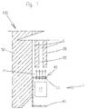
Figure 1 is a schematic partial and sectional view of a transformer comprising a cooling arrangement according to the present invention; -
Figure 2 is a schematic partial and sectional view of the transformer offigure 1 with an electric shielding device and comprising the cooling arrangement of the present invention; -
Figure 3 is a schematic partial and plan view of a first embodiment of the present invention; and -
Figure 4 is a schematic partial and plan view of a second embodiment of the present invention. - In
figure 1 it is shown a partial section of a dry-type transformer 100 which comprises a cooling arrangement 1 according to the present invention. Thetransformer 100 may be one of a high voltage HV / low voltage LV type but any other voltage level could be used. In the present example the rated power may be in the range of 0.1 - 100 MVA and the low voltage may be in the range of 0.1 - 400 kV. - As can be seen in
figures 1-2 thepresent transformer 100 may comprise an inner winding 20 of LV surrounding acore 50 and an outer winding 30 of HV surrounding thecore 50, the inner winding 20 may be placed at least partially between the core 50 and the outer winding 30. Anexemplary transformer 100 could be a dry-type transformer "HiDry" by ABB. Therefore the use of "inner" and "outer" may be related to the location of thecore 50. - The
transformer 100 may be provided with a clampingstructure 40 which may comprise at least aclamp 41 and additionally anelectric shielding device 42. Theclamp 41 may have a U-profile or may have a form of a bended plate and may be manufactured for instance with carbon steel. Theelectric shielding device 42 may comprise a protective sheet and may be positionable between the winding 20, 30 and theclamp 41. Thiselectric shielding device 42 may be configured for shielding theclamp 41 from an electric field of the winding 20, 30. - The
electric shielding device 42 may comprise a material chosen from the group which comprise steel and aluminium but generally any conducting material with suitable mechanical properties. - As per
figures 1-2 the present cooling arrangement 1 may comprise: - a
blowing equipment 11 configured to blow at least one gas flow F. The gas may be air or any other suitable cooling gas; - at least one
opening 12 which may be positionable in a clampingstructure 40 of thetransformer 100; - the
opening 12 may be configured to allow the gas flow F to pass from the blowingequipment 11 towards at least one winding 20, 30 of thetransformer 100; and - the
opening 12 may comprise an electric protecting means 14. - The blowing
equipment 11 may comprise at least one fan which has for instance a flow rate between 250 m3/h and 5000 m3/h and may be a centrifugal-type fan. Those flow rates and type may be modified depending on the requirements of each case. Infigures 1-2 only one fan has been illustrated for bothwindings blowing equipment 11 may comprise at least one fan adapted to direct the gas flow F to the inner winding 20 and at least one fan adapted to direct the gas flow F to the outer winding 30. - In further alternative examples at least one fan may be adapted to direct the gas flow F to the inner winding 20 through the
opening 12 and an additional fan may be adapted to direct the gas flow F to the outer winding 30 out of theopening 12. - In
Figure 1 a sectional view of atransformer 100 with the clampingstructure 40 void ofelectric shielding device 42 is shown. The clampingstructure 40 may comprise theclamp 41 withoutelectric shielding device 42. In this case theopening 12 may be positioned in theclamp 41. The opening 12 may be positioned at least partially in theclamp 41. - In
Figure 2 the clampingstructure 40 further comprises at least oneelectric shielding device 42 positionable between theclamp 41 and the winding 20, 30, and theopening 12 may be positionable in theelectric shielding device 42 and theclamp 41 or only in theelectric shielding device 42. It can be seen inFigure 2 that the both theelectric shielding device 42 and theclamp 41 may be provided withcorresponding openings 12 wherein theopenings 12 may substantially match each other. However, theopenings 12 may match partially each other. In any case theopening 12 may be positioned in order to allow the gas flow F to pass from the blowingequipment 11 to thewindings -
Figure 3 shows a plan view of a first embodiment of the present cooling arrangement 1, wherein the electric protecting means 14 may comprise a slottedportion 16, the slottedportion 16 being configured to define a plurality of holes. The plurality of holes of the slottedportion 16 may be shaped in any suitable form such as a square, circle, rectangle, triangle, oval, etc. -
Figure 4 shows a plan view of a second embodiment of the present cooling arrangement 1, wherein the electric protecting means 14 may comprise agrid 15, thegrid 15 being configured to define a plurality of holes. The plurality of holes of thegrid 15 may be shaped in any suitable form such as a square, circle, rectangle, triangle, oval, etc. - Alternatively the electric protecting means 14 may be integrally formed (not shown) with the clamping
structure 40. This may be the case for instance wherein a plurality of drills, bores or the like are produced in theelectric shielding device 42 or theclamp 41. Therefore thegrid 15 and/or the slottedportion 16 may be configured either as a separate or integral part from/of the clampingstructure 40. - Both the slotted
portion 16 and thegrid 15 may be adapted for orienting and/or distributing the gas flow F as desired. - As can be seen in
figures 1-2 theblowing equipment 11 may be configured in such a way that the outlet of the fan may be directed to the inner and/or the outer winding 20, 30. The gas flow F may reach at least a portion of the surface of the winding 20, 30 taking advantage of theopening 12. The gas flow F may be made to run through interstice spaces S provided between thewindings core 50. A convective heat transfer may be caused by running the gas flow F over at least a surface portion of thewindings windings windings windings - Owing to the
opening 12 the relative cooler gas flow F may reach surface portions of thewindings - The relative positioning of the outlet of the
blowing equipment 11 towindings blowing equipment 11 at the bottom of thetransformer 100, near the clampingstructure 40. Other alternatives may be chosen by the skilled person for positioning theblowing equipment 11 relative to thetransformer 100. - If the
blowing equipment 11 comprises more than one fan the outlet of a second one may be directed to an outer surface of the outer winding 30 for instance. - Several tests were carried out on the present cooling arrangement for dry-type transformers. Air speed, thermal and dielectric measurements were performed. Those tests confirmed that the present invention may provide for a significant uprating of the cooling power and at the same time no dielectric issue may be created.
- Although only a number of examples have been disclosed herein, other alternatives, modifications, uses and/or equivalents thereof are possible. Furthermore, all possible combinations of the described examples are also covered. Thus, the scope of the present disclosure should not be limited by particular examples, but should be determined only by a fair reading of the claims that follow. If reference signs related to drawings are placed in parentheses in a claim, they are solely for attempting to increase the intelligibility of the claim, and shall not be construed as limiting the scope of the claim.
Claims (13)
- Cooling arrangement for a dry-type transformer, the arrangement comprising:a blowing equipment configured to blow at least one gas flow;at least one opening positionable at least partially in a clamping structure of the transformer;the opening being configured to allow the gas flow to pass from the blowing equipment towards at least one winding of the transformer;the opening comprising an electric protecting means.
- Cooling arrangement according to claim 1, wherein the clamping structure comprises at least one clamp and the opening is positionable at least partially in the clamp.
- Cooling arrangement according to claim 2, wherein the clamping structure further comprises at least one electric shielding device positionable between the clamp and the winding, and the opening is positionable at least partially in the electric shielding device and/or the clamp.
- Cooling arrangement according to any of claims 1-3, wherein the electric protecting means comprises a grid, the grid being configured to define a plurality of holes.
- Cooling arrangement according to any of claims 1-3, wherein the electric protecting means comprises a slotted portion, the slotted portion being configured to define a plurality of holes.
- Cooling arrangement according to any of claims 1-5, wherein the electric protecting means is integrally formed with the clamping structure.
- Cooling arrangement according to any of claims 1-6, wherein the blowing equipment has a flow rate of at least 250 m3/h.
- Cooling arrangement according to any of claims 1-7, wherein the transformer comprises an inner winding surrounding at least partially a core and an outer winding surrounding at least partially the core, the inner winding being placed at least partially between the core and the outer winding, wherein the at least one opening is configured to allow the gas flow to pass from the blowing equipment towards the inner winding.
- Cooling arrangement according to any of claims 1-8, wherein the blowing equipment comprises at least one fan.
- Cooling arrangement according to claim 8, wherein the blowing equipment comprises at least one fan adapted to direct the gas flow to the inner winding and at least one fan adapted to direct the gas flow to the outer winding.
- Cooling arrangement according to claim 3, wherein the electric shielding device comprises a protective sheet.
- Cooling arrangement according to any of claims 1-11, wherein the gas is air.
- Transformer comprising a cooling arrangement according to any of claims 1-12.
Priority Applications (5)
| Application Number | Priority Date | Filing Date | Title |
|---|---|---|---|
| ES16173947T ES2877111T3 (en) | 2016-06-10 | 2016-06-10 | Refrigeration arrangement |
| EP16173947.9A EP3255644B1 (en) | 2016-06-10 | 2016-06-10 | Cooling arrangement |
| CN201710404933.0A CN107492438B (en) | 2016-06-10 | 2017-06-01 | Cooling units and transformers |
| KR1020170070633A KR102402405B1 (en) | 2016-06-10 | 2017-06-07 | Cooling arrangement |
| US15/617,916 US10643777B2 (en) | 2016-06-10 | 2017-06-08 | Cooling arrangement |
Applications Claiming Priority (1)
| Application Number | Priority Date | Filing Date | Title |
|---|---|---|---|
| EP16173947.9A EP3255644B1 (en) | 2016-06-10 | 2016-06-10 | Cooling arrangement |
Publications (2)
| Publication Number | Publication Date |
|---|---|
| EP3255644A1 true EP3255644A1 (en) | 2017-12-13 |
| EP3255644B1 EP3255644B1 (en) | 2021-06-02 |
Family
ID=56117632
Family Applications (1)
| Application Number | Title | Priority Date | Filing Date |
|---|---|---|---|
| EP16173947.9A Active EP3255644B1 (en) | 2016-06-10 | 2016-06-10 | Cooling arrangement |
Country Status (5)
| Country | Link |
|---|---|
| US (1) | US10643777B2 (en) |
| EP (1) | EP3255644B1 (en) |
| KR (1) | KR102402405B1 (en) |
| CN (1) | CN107492438B (en) |
| ES (1) | ES2877111T3 (en) |
Cited By (1)
| Publication number | Priority date | Publication date | Assignee | Title |
|---|---|---|---|---|
| CN118073052A (en) * | 2024-04-19 | 2024-05-24 | 山东晨宇电气股份有限公司 | Guide air-cooled dry type transformer |
Families Citing this family (2)
| Publication number | Priority date | Publication date | Assignee | Title |
|---|---|---|---|---|
| CA3116099C (en) | 2018-11-29 | 2024-03-26 | Yong Wang | Transformer cooling system and transformer installation |
| CN214203391U (en) * | 2020-11-26 | 2021-09-14 | Abb电网瑞士股份公司 | Transformer with airflow redirector |
Citations (3)
| Publication number | Priority date | Publication date | Assignee | Title |
|---|---|---|---|---|
| US4725804A (en) * | 1984-05-24 | 1988-02-16 | Square D Company | Electrostatic fork shield |
| DE10238521A1 (en) * | 2002-08-16 | 2004-03-04 | Siemens Ag | winding arrangement |
| EP2430643B1 (en) | 2010-06-28 | 2012-09-12 | ABB Technology AG | Transformer with shielded clamps |
Family Cites Families (14)
| Publication number | Priority date | Publication date | Assignee | Title |
|---|---|---|---|---|
| US2942213A (en) * | 1959-03-27 | 1960-06-21 | Gen Electric | Winding arrangement for electrical apparatus |
| US3376531A (en) * | 1966-08-26 | 1968-04-02 | Westinghouse Electric Corp | Electrical inductive apparatus with wire cloth shielding means |
| DE3243595C2 (en) * | 1982-11-25 | 1985-10-17 | Smit Transformatoren B.V., Nijmegen | Winding arrangement for a gas-cooled transformer |
| JPS63312610A (en) * | 1987-06-16 | 1988-12-21 | Toshiba Corp | Foil wound transformer |
| US4977301A (en) * | 1988-10-13 | 1990-12-11 | Matsushita Electric Industrial Co., Ltd. | High-frequency heating apparatus using frequency-converter-type power supply |
| JP3589012B2 (en) * | 1998-03-27 | 2004-11-17 | 株式会社日立製作所 | Stationary induction appliance |
| JP2008294377A (en) | 2007-05-28 | 2008-12-04 | Densei Lambda Kk | Clamp for magnetic parts |
| CN201311835Y (en) * | 2008-10-17 | 2009-09-16 | 广州骏发电气有限公司 | Dry-type transformer with tapping gear protective device |
| WO2012000983A1 (en) * | 2010-06-28 | 2012-01-05 | Abb Technology Ag | Transformer with shielding rings in windings |
| CN103208348B (en) * | 2013-03-15 | 2015-09-02 | 武汉振源电气股份有限公司 | The removable large-scale series connection iron core reactor of oil immersed type |
| US20150109090A1 (en) * | 2013-10-21 | 2015-04-23 | Hammond Power Solutions, Inc. | Electrical transformer with a shielded cast coil assembly |
| CN203826171U (en) * | 2014-01-14 | 2014-09-10 | 万电电气有限公司 | Dry type transformer |
| JP2015228442A (en) | 2014-06-02 | 2015-12-17 | 株式会社東芝 | Gas-insulated stationary device |
| CN204087991U (en) * | 2014-09-04 | 2015-01-07 | 浙江金盘变压器有限公司 | Dry-type transformer |
-
2016
- 2016-06-10 ES ES16173947T patent/ES2877111T3/en active Active
- 2016-06-10 EP EP16173947.9A patent/EP3255644B1/en active Active
-
2017
- 2017-06-01 CN CN201710404933.0A patent/CN107492438B/en active Active
- 2017-06-07 KR KR1020170070633A patent/KR102402405B1/en active Active
- 2017-06-08 US US15/617,916 patent/US10643777B2/en active Active
Patent Citations (3)
| Publication number | Priority date | Publication date | Assignee | Title |
|---|---|---|---|---|
| US4725804A (en) * | 1984-05-24 | 1988-02-16 | Square D Company | Electrostatic fork shield |
| DE10238521A1 (en) * | 2002-08-16 | 2004-03-04 | Siemens Ag | winding arrangement |
| EP2430643B1 (en) | 2010-06-28 | 2012-09-12 | ABB Technology AG | Transformer with shielded clamps |
Cited By (1)
| Publication number | Priority date | Publication date | Assignee | Title |
|---|---|---|---|---|
| CN118073052A (en) * | 2024-04-19 | 2024-05-24 | 山东晨宇电气股份有限公司 | Guide air-cooled dry type transformer |
Also Published As
| Publication number | Publication date |
|---|---|
| KR102402405B1 (en) | 2022-05-25 |
| CN107492438A (en) | 2017-12-19 |
| ES2877111T3 (en) | 2021-11-16 |
| CN107492438B (en) | 2021-01-22 |
| US10643777B2 (en) | 2020-05-05 |
| US20170358390A1 (en) | 2017-12-14 |
| KR20170140087A (en) | 2017-12-20 |
| EP3255644B1 (en) | 2021-06-02 |
Similar Documents
| Publication | Publication Date | Title |
|---|---|---|
| US10644557B2 (en) | Stator used for motor, motor and ventilation cooling method for motor | |
| US20070247266A1 (en) | Compact Dry Transformer | |
| US11355976B2 (en) | Integral fluid cooling of electrical machine | |
| ES2657308T3 (en) | Power transformer cooling device | |
| US10643777B2 (en) | Cooling arrangement | |
| EP3024004A1 (en) | Air-cooled reactor | |
| EP3888105B1 (en) | Transformer cooling system and transformer installation | |
| US10587167B2 (en) | Rotor assembly having improved cooling path | |
| HUT71078A (en) | Gas cooled electric machine | |
| CN102543372A (en) | Amorphous transformer core | |
| US20200258670A1 (en) | Reactor, motor driver, power conditioner and machine | |
| CA3048931C (en) | Transformer with air guiding plates | |
| US20210083542A1 (en) | Electric machine and hybrid electric aircraft | |
| US2942213A (en) | Winding arrangement for electrical apparatus | |
| JP3138852B2 (en) | Transformer | |
| US20180053593A1 (en) | Transformer embedded with thermally conductive member | |
| EP3921855B1 (en) | Inductors with core structure supporting multiple air flow modes | |
| ES2388433T3 (en) | Conductor for liquid-cooled coils | |
| CN220252991U (en) | Air-cooled transformer | |
| KR200381493Y1 (en) | Cool down structure of the vertical transformer | |
| KR101243291B1 (en) | Apparatus of air cooling for stator coils of superconduting motor or generator | |
| RU2692781C1 (en) | Electric machine with variable cooling system | |
| BRPI0610194B1 (en) | PROTECTIVE SYSTEM FOR ON-LINE BUSHING OF AN ELECTRICAL INSTALLATION AND CONNECTION ELEMENT TO HOLD AND FIX WALL ELEMENTS | |
| KR20220061229A (en) | Insulation Assemblies, Transformer Assemblies and Dry Type Transformers | |
| KR19990058914A (en) | Cooling device of linear induction motor |
Legal Events
| Date | Code | Title | Description |
|---|---|---|---|
| PUAI | Public reference made under article 153(3) epc to a published international application that has entered the european phase |
Free format text: ORIGINAL CODE: 0009012 |
|
| STAA | Information on the status of an ep patent application or granted ep patent |
Free format text: STATUS: THE APPLICATION HAS BEEN PUBLISHED |
|
| AK | Designated contracting states |
Kind code of ref document: A1 Designated state(s): AL AT BE BG CH CY CZ DE DK EE ES FI FR GB GR HR HU IE IS IT LI LT LU LV MC MK MT NL NO PL PT RO RS SE SI SK SM TR |
|
| AX | Request for extension of the european patent |
Extension state: BA ME |
|
| STAA | Information on the status of an ep patent application or granted ep patent |
Free format text: STATUS: REQUEST FOR EXAMINATION WAS MADE |
|
| 17P | Request for examination filed |
Effective date: 20180613 |
|
| RBV | Designated contracting states (corrected) |
Designated state(s): AL AT BE BG CH CY CZ DE DK EE ES FI FR GB GR HR HU IE IS IT LI LT LU LV MC MK MT NL NO PL PT RO RS SE SI SK SM TR |
|
| GRAP | Despatch of communication of intention to grant a patent |
Free format text: ORIGINAL CODE: EPIDOSNIGR1 |
|
| STAA | Information on the status of an ep patent application or granted ep patent |
Free format text: STATUS: GRANT OF PATENT IS INTENDED |
|
| INTG | Intention to grant announced |
Effective date: 20200130 |
|
| GRAJ | Information related to disapproval of communication of intention to grant by the applicant or resumption of examination proceedings by the epo deleted |
Free format text: ORIGINAL CODE: EPIDOSDIGR1 |
|
| STAA | Information on the status of an ep patent application or granted ep patent |
Free format text: STATUS: REQUEST FOR EXAMINATION WAS MADE |
|
| STAA | Information on the status of an ep patent application or granted ep patent |
Free format text: STATUS: EXAMINATION IS IN PROGRESS |
|
| INTC | Intention to grant announced (deleted) | ||
| 17Q | First examination report despatched |
Effective date: 20200414 |
|
| GRAP | Despatch of communication of intention to grant a patent |
Free format text: ORIGINAL CODE: EPIDOSNIGR1 |
|
| STAA | Information on the status of an ep patent application or granted ep patent |
Free format text: STATUS: GRANT OF PATENT IS INTENDED |
|
| INTG | Intention to grant announced |
Effective date: 20210122 |
|
| RAP1 | Party data changed (applicant data changed or rights of an application transferred) |
Owner name: ABB POWER GRIDS SWITZERLAND AG |
|
| GRAS | Grant fee paid |
Free format text: ORIGINAL CODE: EPIDOSNIGR3 |
|
| GRAA | (expected) grant |
Free format text: ORIGINAL CODE: 0009210 |
|
| STAA | Information on the status of an ep patent application or granted ep patent |
Free format text: STATUS: THE PATENT HAS BEEN GRANTED |
|
| REG | Reference to a national code |
Ref country code: CH Ref legal event code: EP |
|
| AK | Designated contracting states |
Kind code of ref document: B1 Designated state(s): AL AT BE BG CH CY CZ DE DK EE ES FI FR GB GR HR HU IE IS IT LI LT LU LV MC MK MT NL NO PL PT RO RS SE SI SK SM TR |
|
| REG | Reference to a national code |
Ref country code: GB Ref legal event code: FG4D |
|
| RIN1 | Information on inventor provided before grant (corrected) |
Inventor name: NOGUES BARRIERAS, ANTONIO Inventor name: ROY MARTIN, CARLOS Inventor name: SANCHEZ, LUIS Inventor name: MURILLO, RAFAEL Inventor name: CEBRIAN LLES, LORENA Inventor name: MAINAR JOVEN, CARLOS |
|
| REG | Reference to a national code |
Ref country code: AT Ref legal event code: REF Ref document number: 1399212 Country of ref document: AT Kind code of ref document: T Effective date: 20210615 |
|
| REG | Reference to a national code |
Ref country code: IE Ref legal event code: FG4D |
|
| REG | Reference to a national code |
Ref country code: DE Ref legal event code: R096 Ref document number: 602016058720 Country of ref document: DE |
|
| REG | Reference to a national code |
Ref country code: LT Ref legal event code: MG9D |
|
| PG25 | Lapsed in a contracting state [announced via postgrant information from national office to epo] |
Ref country code: HR Free format text: LAPSE BECAUSE OF FAILURE TO SUBMIT A TRANSLATION OF THE DESCRIPTION OR TO PAY THE FEE WITHIN THE PRESCRIBED TIME-LIMIT Effective date: 20210602 Ref country code: BG Free format text: LAPSE BECAUSE OF FAILURE TO SUBMIT A TRANSLATION OF THE DESCRIPTION OR TO PAY THE FEE WITHIN THE PRESCRIBED TIME-LIMIT Effective date: 20210902 Ref country code: FI Free format text: LAPSE BECAUSE OF FAILURE TO SUBMIT A TRANSLATION OF THE DESCRIPTION OR TO PAY THE FEE WITHIN THE PRESCRIBED TIME-LIMIT Effective date: 20210602 Ref country code: LT Free format text: LAPSE BECAUSE OF FAILURE TO SUBMIT A TRANSLATION OF THE DESCRIPTION OR TO PAY THE FEE WITHIN THE PRESCRIBED TIME-LIMIT Effective date: 20210602 |
|
| REG | Reference to a national code |
Ref country code: NL Ref legal event code: MP Effective date: 20210602 |
|
| REG | Reference to a national code |
Ref country code: AT Ref legal event code: MK05 Ref document number: 1399212 Country of ref document: AT Kind code of ref document: T Effective date: 20210602 |
|
| REG | Reference to a national code |
Ref country code: ES Ref legal event code: FG2A Ref document number: 2877111 Country of ref document: ES Kind code of ref document: T3 Effective date: 20211116 |
|
| PG25 | Lapsed in a contracting state [announced via postgrant information from national office to epo] |
Ref country code: LV Free format text: LAPSE BECAUSE OF FAILURE TO SUBMIT A TRANSLATION OF THE DESCRIPTION OR TO PAY THE FEE WITHIN THE PRESCRIBED TIME-LIMIT Effective date: 20210602 Ref country code: GR Free format text: LAPSE BECAUSE OF FAILURE TO SUBMIT A TRANSLATION OF THE DESCRIPTION OR TO PAY THE FEE WITHIN THE PRESCRIBED TIME-LIMIT Effective date: 20210903 Ref country code: NO Free format text: LAPSE BECAUSE OF FAILURE TO SUBMIT A TRANSLATION OF THE DESCRIPTION OR TO PAY THE FEE WITHIN THE PRESCRIBED TIME-LIMIT Effective date: 20210902 Ref country code: PL Free format text: LAPSE BECAUSE OF FAILURE TO SUBMIT A TRANSLATION OF THE DESCRIPTION OR TO PAY THE FEE WITHIN THE PRESCRIBED TIME-LIMIT Effective date: 20210602 Ref country code: SE Free format text: LAPSE BECAUSE OF FAILURE TO SUBMIT A TRANSLATION OF THE DESCRIPTION OR TO PAY THE FEE WITHIN THE PRESCRIBED TIME-LIMIT Effective date: 20210602 Ref country code: RS Free format text: LAPSE BECAUSE OF FAILURE TO SUBMIT A TRANSLATION OF THE DESCRIPTION OR TO PAY THE FEE WITHIN THE PRESCRIBED TIME-LIMIT Effective date: 20210602 |
|
| RAP4 | Party data changed (patent owner data changed or rights of a patent transferred) |
Owner name: HITACHI ENERGY SWITZERLAND AG |
|
| PG25 | Lapsed in a contracting state [announced via postgrant information from national office to epo] |
Ref country code: EE Free format text: LAPSE BECAUSE OF FAILURE TO SUBMIT A TRANSLATION OF THE DESCRIPTION OR TO PAY THE FEE WITHIN THE PRESCRIBED TIME-LIMIT Effective date: 20210602 Ref country code: CZ Free format text: LAPSE BECAUSE OF FAILURE TO SUBMIT A TRANSLATION OF THE DESCRIPTION OR TO PAY THE FEE WITHIN THE PRESCRIBED TIME-LIMIT Effective date: 20210602 Ref country code: SM Free format text: LAPSE BECAUSE OF FAILURE TO SUBMIT A TRANSLATION OF THE DESCRIPTION OR TO PAY THE FEE WITHIN THE PRESCRIBED TIME-LIMIT Effective date: 20210602 Ref country code: SK Free format text: LAPSE BECAUSE OF FAILURE TO SUBMIT A TRANSLATION OF THE DESCRIPTION OR TO PAY THE FEE WITHIN THE PRESCRIBED TIME-LIMIT Effective date: 20210602 Ref country code: AT Free format text: LAPSE BECAUSE OF FAILURE TO SUBMIT A TRANSLATION OF THE DESCRIPTION OR TO PAY THE FEE WITHIN THE PRESCRIBED TIME-LIMIT Effective date: 20210602 Ref country code: RO Free format text: LAPSE BECAUSE OF FAILURE TO SUBMIT A TRANSLATION OF THE DESCRIPTION OR TO PAY THE FEE WITHIN THE PRESCRIBED TIME-LIMIT Effective date: 20210602 Ref country code: NL Free format text: LAPSE BECAUSE OF FAILURE TO SUBMIT A TRANSLATION OF THE DESCRIPTION OR TO PAY THE FEE WITHIN THE PRESCRIBED TIME-LIMIT Effective date: 20210602 Ref country code: PT Free format text: LAPSE BECAUSE OF FAILURE TO SUBMIT A TRANSLATION OF THE DESCRIPTION OR TO PAY THE FEE WITHIN THE PRESCRIBED TIME-LIMIT Effective date: 20211004 |
|
| REG | Reference to a national code |
Ref country code: CH Ref legal event code: PL |
|
| REG | Reference to a national code |
Ref country code: DE Ref legal event code: R097 Ref document number: 602016058720 Country of ref document: DE |
|
| REG | Reference to a national code |
Ref country code: BE Ref legal event code: MM Effective date: 20210630 |
|
| PG25 | Lapsed in a contracting state [announced via postgrant information from national office to epo] |
Ref country code: MC Free format text: LAPSE BECAUSE OF FAILURE TO SUBMIT A TRANSLATION OF THE DESCRIPTION OR TO PAY THE FEE WITHIN THE PRESCRIBED TIME-LIMIT Effective date: 20210602 Ref country code: LU Free format text: LAPSE BECAUSE OF NON-PAYMENT OF DUE FEES Effective date: 20210610 |
|
| PLBE | No opposition filed within time limit |
Free format text: ORIGINAL CODE: 0009261 |
|
| STAA | Information on the status of an ep patent application or granted ep patent |
Free format text: STATUS: NO OPPOSITION FILED WITHIN TIME LIMIT |
|
| PG25 | Lapsed in a contracting state [announced via postgrant information from national office to epo] |
Ref country code: LI Free format text: LAPSE BECAUSE OF NON-PAYMENT OF DUE FEES Effective date: 20210630 Ref country code: IE Free format text: LAPSE BECAUSE OF NON-PAYMENT OF DUE FEES Effective date: 20210610 Ref country code: DK Free format text: LAPSE BECAUSE OF FAILURE TO SUBMIT A TRANSLATION OF THE DESCRIPTION OR TO PAY THE FEE WITHIN THE PRESCRIBED TIME-LIMIT Effective date: 20210602 Ref country code: CH Free format text: LAPSE BECAUSE OF NON-PAYMENT OF DUE FEES Effective date: 20210630 |
|
| 26N | No opposition filed |
Effective date: 20220303 |
|
| PG25 | Lapsed in a contracting state [announced via postgrant information from national office to epo] |
Ref country code: AL Free format text: LAPSE BECAUSE OF FAILURE TO SUBMIT A TRANSLATION OF THE DESCRIPTION OR TO PAY THE FEE WITHIN THE PRESCRIBED TIME-LIMIT Effective date: 20210602 |
|
| REG | Reference to a national code |
Ref country code: DE Ref legal event code: R081 Ref document number: 602016058720 Country of ref document: DE Owner name: HITACHI ENERGY SWITZERLAND AG, CH Free format text: FORMER OWNER: ABB POWER GRIDS SWITZERLAND AG, BADEN, CH Ref country code: DE Ref legal event code: R081 Ref document number: 602016058720 Country of ref document: DE Owner name: HITACHI ENERGY LTD, CH Free format text: FORMER OWNER: ABB POWER GRIDS SWITZERLAND AG, BADEN, CH |
|
| PG25 | Lapsed in a contracting state [announced via postgrant information from national office to epo] |
Ref country code: BE Free format text: LAPSE BECAUSE OF NON-PAYMENT OF DUE FEES Effective date: 20210630 |
|
| PG25 | Lapsed in a contracting state [announced via postgrant information from national office to epo] |
Ref country code: HU Free format text: LAPSE BECAUSE OF FAILURE TO SUBMIT A TRANSLATION OF THE DESCRIPTION OR TO PAY THE FEE WITHIN THE PRESCRIBED TIME-LIMIT; INVALID AB INITIO Effective date: 20160610 |
|
| PG25 | Lapsed in a contracting state [announced via postgrant information from national office to epo] |
Ref country code: CY Free format text: LAPSE BECAUSE OF FAILURE TO SUBMIT A TRANSLATION OF THE DESCRIPTION OR TO PAY THE FEE WITHIN THE PRESCRIBED TIME-LIMIT Effective date: 20210602 |
|
| P01 | Opt-out of the competence of the unified patent court (upc) registered |
Effective date: 20230527 |
|
| REG | Reference to a national code |
Ref country code: DE Ref legal event code: R082 Ref document number: 602016058720 Country of ref document: DE Representative=s name: DENNEMEYER & ASSOCIATES RECHTSANWALTSGESELLSCH, DE Ref country code: DE Ref legal event code: R082 Ref document number: 602016058720 Country of ref document: DE Representative=s name: DENNEMEYER & ASSOCIATES S.A., DE Ref country code: DE Ref legal event code: R081 Ref document number: 602016058720 Country of ref document: DE Owner name: HITACHI ENERGY LTD, CH Free format text: FORMER OWNER: HITACHI ENERGY SWITZERLAND AG, BADEN, CH |
|
| PG25 | Lapsed in a contracting state [announced via postgrant information from national office to epo] |
Ref country code: MK Free format text: LAPSE BECAUSE OF FAILURE TO SUBMIT A TRANSLATION OF THE DESCRIPTION OR TO PAY THE FEE WITHIN THE PRESCRIBED TIME-LIMIT Effective date: 20210602 |
|
| REG | Reference to a national code |
Ref country code: GB Ref legal event code: 732E Free format text: REGISTERED BETWEEN 20240718 AND 20240724 |
|
| PG25 | Lapsed in a contracting state [announced via postgrant information from national office to epo] |
Ref country code: MT Free format text: LAPSE BECAUSE OF FAILURE TO SUBMIT A TRANSLATION OF THE DESCRIPTION OR TO PAY THE FEE WITHIN THE PRESCRIBED TIME-LIMIT Effective date: 20210602 |
|
| REG | Reference to a national code |
Ref country code: ES Ref legal event code: PC2A Owner name: HITACHI ENERGY LTD Effective date: 20240925 |
|
| REG | Reference to a national code |
Ref country code: DE Ref legal event code: R082 Ref document number: 602016058720 Country of ref document: DE Representative=s name: DENNEMEYER & ASSOCIATES RECHTSANWALTSGESELLSCH, DE |
|
| PGFP | Annual fee paid to national office [announced via postgrant information from national office to epo] |
Ref country code: DE Payment date: 20250618 Year of fee payment: 10 |
|
| PGFP | Annual fee paid to national office [announced via postgrant information from national office to epo] |
Ref country code: GB Payment date: 20250618 Year of fee payment: 10 |
|
| PGFP | Annual fee paid to national office [announced via postgrant information from national office to epo] |
Ref country code: FR Payment date: 20250625 Year of fee payment: 10 |
|
| PGFP | Annual fee paid to national office [announced via postgrant information from national office to epo] |
Ref country code: ES Payment date: 20250728 Year of fee payment: 10 |
|
| PGFP | Annual fee paid to national office [announced via postgrant information from national office to epo] |
Ref country code: IT Payment date: 20250624 Year of fee payment: 10 |
|
| PG25 | Lapsed in a contracting state [announced via postgrant information from national office to epo] |
Ref country code: TR Free format text: LAPSE BECAUSE OF FAILURE TO SUBMIT A TRANSLATION OF THE DESCRIPTION OR TO PAY THE FEE WITHIN THE PRESCRIBED TIME-LIMIT Effective date: 20210602 |