EP3255475A2 - Laser scanning microscope, and laser scanning microscope control method - Google Patents
Laser scanning microscope, and laser scanning microscope control method Download PDFInfo
- Publication number
- EP3255475A2 EP3255475A2 EP17173192.0A EP17173192A EP3255475A2 EP 3255475 A2 EP3255475 A2 EP 3255475A2 EP 17173192 A EP17173192 A EP 17173192A EP 3255475 A2 EP3255475 A2 EP 3255475A2
- Authority
- EP
- European Patent Office
- Prior art keywords
- optical element
- specimen
- scanning microscope
- laser scanning
- laser
- Prior art date
- Legal status (The legal status is an assumption and is not a legal conclusion. Google has not performed a legal analysis and makes no representation as to the accuracy of the status listed.)
- Withdrawn
Links
- 238000000034 method Methods 0.000 title claims description 20
- 230000003287 optical effect Effects 0.000 claims abstract description 192
- 238000001514 detection method Methods 0.000 claims abstract description 84
- 238000003780 insertion Methods 0.000 claims description 19
- 230000037431 insertion Effects 0.000 claims description 19
- 230000003321 amplification Effects 0.000 claims description 17
- 238000003199 nucleic acid amplification method Methods 0.000 claims description 17
- 210000001747 pupil Anatomy 0.000 claims description 15
- 238000009792 diffusion process Methods 0.000 claims description 13
- 230000004907 flux Effects 0.000 claims description 2
- 230000005540 biological transmission Effects 0.000 description 68
- 238000012545 processing Methods 0.000 description 25
- 238000005286 illumination Methods 0.000 description 10
- 230000008859 change Effects 0.000 description 6
- 238000002073 fluorescence micrograph Methods 0.000 description 6
- 230000009471 action Effects 0.000 description 4
- 238000010586 diagram Methods 0.000 description 4
- 230000007246 mechanism Effects 0.000 description 4
- 230000002093 peripheral effect Effects 0.000 description 4
- 230000008569 process Effects 0.000 description 4
- 230000000694 effects Effects 0.000 description 3
- 230000006870 function Effects 0.000 description 3
- 230000003247 decreasing effect Effects 0.000 description 1
- 230000007812 deficiency Effects 0.000 description 1
- 238000005516 engineering process Methods 0.000 description 1
- 230000003993 interaction Effects 0.000 description 1
- 238000013507 mapping Methods 0.000 description 1
- 238000012986 modification Methods 0.000 description 1
- 230000004048 modification Effects 0.000 description 1
- 230000001629 suppression Effects 0.000 description 1
Images














Classifications
-
- G—PHYSICS
- G02—OPTICS
- G02B—OPTICAL ELEMENTS, SYSTEMS OR APPARATUS
- G02B21/00—Microscopes
- G02B21/0004—Microscopes specially adapted for specific applications
- G02B21/002—Scanning microscopes
- G02B21/0024—Confocal scanning microscopes (CSOMs) or confocal "macroscopes"; Accessories which are not restricted to use with CSOMs, e.g. sample holders
- G02B21/0036—Scanning details, e.g. scanning stages
- G02B21/0048—Scanning details, e.g. scanning stages scanning mirrors, e.g. rotating or galvanomirrors, MEMS mirrors
-
- G—PHYSICS
- G01—MEASURING; TESTING
- G01N—INVESTIGATING OR ANALYSING MATERIALS BY DETERMINING THEIR CHEMICAL OR PHYSICAL PROPERTIES
- G01N21/00—Investigating or analysing materials by the use of optical means, i.e. using sub-millimetre waves, infrared, visible or ultraviolet light
- G01N21/62—Systems in which the material investigated is excited whereby it emits light or causes a change in wavelength of the incident light
- G01N21/63—Systems in which the material investigated is excited whereby it emits light or causes a change in wavelength of the incident light optically excited
- G01N21/64—Fluorescence; Phosphorescence
-
- G—PHYSICS
- G01—MEASURING; TESTING
- G01N—INVESTIGATING OR ANALYSING MATERIALS BY DETERMINING THEIR CHEMICAL OR PHYSICAL PROPERTIES
- G01N21/00—Investigating or analysing materials by the use of optical means, i.e. using sub-millimetre waves, infrared, visible or ultraviolet light
- G01N21/62—Systems in which the material investigated is excited whereby it emits light or causes a change in wavelength of the incident light
- G01N21/63—Systems in which the material investigated is excited whereby it emits light or causes a change in wavelength of the incident light optically excited
- G01N21/64—Fluorescence; Phosphorescence
- G01N21/645—Specially adapted constructive features of fluorimeters
- G01N21/6456—Spatial resolved fluorescence measurements; Imaging
- G01N21/6458—Fluorescence microscopy
-
- G—PHYSICS
- G02—OPTICS
- G02B—OPTICAL ELEMENTS, SYSTEMS OR APPARATUS
- G02B19/00—Condensers, e.g. light collectors or similar non-imaging optics
- G02B19/0033—Condensers, e.g. light collectors or similar non-imaging optics characterised by the use
- G02B19/0085—Condensers, e.g. light collectors or similar non-imaging optics characterised by the use for use with both a detector and a source
-
- G—PHYSICS
- G02—OPTICS
- G02B—OPTICAL ELEMENTS, SYSTEMS OR APPARATUS
- G02B21/00—Microscopes
- G02B21/0004—Microscopes specially adapted for specific applications
- G02B21/002—Scanning microscopes
- G02B21/0024—Confocal scanning microscopes (CSOMs) or confocal "macroscopes"; Accessories which are not restricted to use with CSOMs, e.g. sample holders
- G02B21/0032—Optical details of illumination, e.g. light-sources, pinholes, beam splitters, slits, fibers
-
- G—PHYSICS
- G02—OPTICS
- G02B—OPTICAL ELEMENTS, SYSTEMS OR APPARATUS
- G02B21/00—Microscopes
- G02B21/0004—Microscopes specially adapted for specific applications
- G02B21/002—Scanning microscopes
- G02B21/0024—Confocal scanning microscopes (CSOMs) or confocal "macroscopes"; Accessories which are not restricted to use with CSOMs, e.g. sample holders
- G02B21/0052—Optical details of the image generation
- G02B21/0064—Optical details of the image generation multi-spectral or wavelength-selective arrangements, e.g. wavelength fan-out, chromatic profiling
-
- G—PHYSICS
- G02—OPTICS
- G02B—OPTICAL ELEMENTS, SYSTEMS OR APPARATUS
- G02B21/00—Microscopes
- G02B21/0004—Microscopes specially adapted for specific applications
- G02B21/002—Scanning microscopes
- G02B21/0024—Confocal scanning microscopes (CSOMs) or confocal "macroscopes"; Accessories which are not restricted to use with CSOMs, e.g. sample holders
- G02B21/0052—Optical details of the image generation
- G02B21/0076—Optical details of the image generation arrangements using fluorescence or luminescence
-
- G—PHYSICS
- G02—OPTICS
- G02B—OPTICAL ELEMENTS, SYSTEMS OR APPARATUS
- G02B21/00—Microscopes
- G02B21/0004—Microscopes specially adapted for specific applications
- G02B21/0088—Inverse microscopes
-
- G—PHYSICS
- G02—OPTICS
- G02B—OPTICAL ELEMENTS, SYSTEMS OR APPARATUS
- G02B21/00—Microscopes
- G02B21/06—Means for illuminating specimens
- G02B21/08—Condensers
- G02B21/086—Condensers for transillumination only
-
- G—PHYSICS
- G02—OPTICS
- G02B—OPTICAL ELEMENTS, SYSTEMS OR APPARATUS
- G02B21/00—Microscopes
- G02B21/16—Microscopes adapted for ultraviolet illumination ; Fluorescence microscopes
-
- G—PHYSICS
- G01—MEASURING; TESTING
- G01N—INVESTIGATING OR ANALYSING MATERIALS BY DETERMINING THEIR CHEMICAL OR PHYSICAL PROPERTIES
- G01N2201/00—Features of devices classified in G01N21/00
- G01N2201/06—Illumination; Optics
-
- G—PHYSICS
- G01—MEASURING; TESTING
- G01N—INVESTIGATING OR ANALYSING MATERIALS BY DETERMINING THEIR CHEMICAL OR PHYSICAL PROPERTIES
- G01N2201/00—Features of devices classified in G01N21/00
- G01N2201/06—Illumination; Optics
- G01N2201/061—Sources
- G01N2201/06113—Coherent sources; lasers
-
- G—PHYSICS
- G02—OPTICS
- G02B—OPTICAL ELEMENTS, SYSTEMS OR APPARATUS
- G02B21/00—Microscopes
- G02B21/0004—Microscopes specially adapted for specific applications
- G02B21/002—Scanning microscopes
- G02B21/0024—Confocal scanning microscopes (CSOMs) or confocal "macroscopes"; Accessories which are not restricted to use with CSOMs, e.g. sample holders
- G02B21/0052—Optical details of the image generation
- G02B21/006—Optical details of the image generation focusing arrangements; selection of the plane to be imaged
-
- G—PHYSICS
- G02—OPTICS
- G02B—OPTICAL ELEMENTS, SYSTEMS OR APPARATUS
- G02B21/00—Microscopes
- G02B21/0004—Microscopes specially adapted for specific applications
- G02B21/002—Scanning microscopes
- G02B21/0024—Confocal scanning microscopes (CSOMs) or confocal "macroscopes"; Accessories which are not restricted to use with CSOMs, e.g. sample holders
- G02B21/008—Details of detection or image processing, including general computer control
-
- G—PHYSICS
- G02—OPTICS
- G02B—OPTICAL ELEMENTS, SYSTEMS OR APPARATUS
- G02B21/00—Microscopes
- G02B21/36—Microscopes arranged for photographic purposes or projection purposes or digital imaging or video purposes including associated control and data processing arrangements
- G02B21/365—Control or image processing arrangements for digital or video microscopes
- G02B21/367—Control or image processing arrangements for digital or video microscopes providing an output produced by processing a plurality of individual source images, e.g. image tiling, montage, composite images, depth sectioning, image comparison
-
- G—PHYSICS
- G02—OPTICS
- G02B—OPTICAL ELEMENTS, SYSTEMS OR APPARATUS
- G02B5/00—Optical elements other than lenses
- G02B5/02—Diffusing elements; Afocal elements
Definitions
- Disclosure of the present invention relates to a laser scanning microscope, and a laser scanning microscope control method.
- a laser scanning microscope for example, that includes a detection lens that faces an objective with a biological specimen interposed between the detection lens and the objective, and a photodetector that detects light that passes through the biological specimen and is condensed by the detection lens (see Japanese Laid-Open Patent Publication No. 2010-102264 ).
- a transmission image that enables the shape of a cell in the biological specimen to be grasped, in addition to a fluorescence image, can be obtained by scanning the biological specimen once.
- vital phenomena that occur in the cell can be observed better by displaying the fluorescence image over the transmission image.
- microscopes have been requested to be capable of observing interactions between cells in addition to phenomena within a cell. Accordingly, laser scanning microscopes have been requested to cope with a wider magnification range than before, and in particular, a wide magnification range including a very low magnification that is lower than 10 times.
- a fluorescence image can be obtained within a wide magnification range by switching and using objectives having magnifications different from each other.
- a transmission image can also be obtained within a wide magnification range by switching detection lenses according to the magnification of the objective.
- a laser scanning microscope that uses a detection lens having a relatively large lens diameter within a wide magnification range in order to suppress vignetting of off-axis light in the detection lens, a laser scanning microscope that includes an auxiliary lens that can be inserted or removed on an object side of a detection lens, and the like have been proposed.
- a laser scanning microscope in one aspect of the present invention includes: an objective that irradiates a specimen with a laser beam; a detection lens that condenses the laser beam that passes through the specimen, the detection lens being arranged so as to face the objective with the specimen interposed between the detection lens and the objective; an optical element that is removably arranged between an image plane on which the detection lens forms an image of the specimen and a first surface that is a lens surface closest to the specimen of the detection lens, the optical element converting the laser beam made incident on the optical element into diffused light or deflecting a portion of the laser beam made incident on the optical element; and a photodetector that detects detection light emitted from the optical element arranged between the image plane and the first surface to the image plane.
- a control method of a laser scanning microscope in another aspect of the present invention includes: controlling insertion or removal of an optical element between an image plane on which a detection lens forms an image of a specimen and a first surface that is a lens surface closest to the specimen of the detection lens in accordance with a magnification of an objective that irradiates the specimen with a laser beam, the optical element converting the laser beam into diffused light or deflecting a portion of the laser beam, the detection lens being arranged so as to face the objective with the specimen interposed between the detection lens and the objective; and controlling at least one of an amplification factor of a photodetector and an output of a laser light source in accordance with the insertion or removal of the optical element, the photodetector detecting detection light emitted from the optical element to the image plane, the laser light source emitting the laser beam.
- a transmission image can be obtained within a wide magnification range without sacrificing a space in which a specimen is arranged and switching detection lenses.
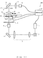
- FIG. 1 illustrates the configuration of a laser scanning microscope 100 according to this embodiment.
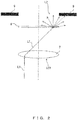
- FIG. 2 is a diagram explaining an action of an optical element 8 included in the laser scanning microscope 100. This embodiment is described below by using a case in which the laser scanning microscope 100 is used to observe a biological specimen as an example.
- the laser scanning microscope 100 includes a laser 1 that emits a laser beam.
- the laser scanning microscope 100 further includes a scanner 2, a relay optical system 3, a mirror 4, and an objective 5 on an illumination light path from the laser 1 to a stage 6.
- the laser 1 is a laser light source that emits a laser beam that excites a specimen.
- the scanner 2 is a two-dimensional scanner that scans a specimen arranged on the stage 6 in a direction orthogonal to an optical axis of the objective 5 by changing a direction in which the laser beam is deflected.
- the scanner 2 includes, for example, a resonant scanner and a galvanometer mirror.
- the relay optical system 3 is an optical system that projects an image of the scanner 2 in or near a pupil position of the objective 5.
- the objective 5 is an infinity-corrected objective, and the objective 5 irradiates the specimen arranged on the stage 6 with a laser beam.
- objectives having various magnifications are switched and used by using a not-illustrated revolver or the like.
- the laser scanning microscope 100 includes a photodetector 12 for transmission detection.
- the laser scanning microscope 100 further includes a detection lens 7, an optical element 8, a field stop 9, a mirror 10, and a relay optical system 11 on an optical path from the stage 6 to the photodetector 12.
- Both the mirror 4 and the mirror 10 described above may be dichroic mirrors, or may be half mirrors.
- another detection optical system and another illumination optical system can be arranged respectively on transmitted light paths of the mirror 4 and the mirror 10 along an optical-axis direction of the objective 5.
- the detection lens 7 is a lens that condenses a laser beam that has passed through the specimen, and the detection lens 7 is arranged so as to face the objective 5 with the stage 6 (or the specimen arranged on the stage 6) interposed between the detection lens 7 and the objective 5.
- the optical element 8 is a light diffusion element that converts a laser beam made incident on the optical element 8 into diffused light, and the optical element 8 is a light diffusion plate in this example.
- the optical element 8 is removably arranged between an image plane IP on which the detection lens 7 forms an image of the specimen and a first surface LS1 that is a lens surface closest to the specimen of the detection lens 7.
- the field stop 9 is provided on the image plane IP that is optically conjugate to a specimen surface (a surface of the stage 6).
- the relay optical system 11 is a relay optical system that projects an exit pupil of the detection lens 7 onto the photodetector 12, and the relay optical system 11 is arranged between the optical element 8 that is arranged between the image plane IP and the first surface LS1, and the photodetector 12.
- the photodetector 12 is a photodetector that outputs a signal according to an intensity of a detected laser beam, and the photodetector 12 is, for example, a photomultiplier tube (PMT).
- PMT photomultiplier tube
- a position in which the laser beam is applied to the specimen changes according to a direction in which the scanner 2 deflects the laser beam.
- the laser beam that has passed through the specimen enters the photodetector 12 regardless of an irradiation position, unless vignetting is generated on the optical path.
- a scanning image of the specimen can be obtained by obtaining luminance data according to a signal that is output from the photodetector 12 in each of the irradiation positions of the laser beam, and two-dimensionally mapping respective pieces of luminance data according to the irradiation positions.
- This scanning image is an image obtained by detecting light that has passed through the specimen, and therefore the scanning image is also referred to as a transmission image.
- the laser scanning microscope 100 As the laser beam condensed by the detection lens 7 moves farther away from an exit pupil position of the detection lens 7 after having passed through the exit pupil position, the laser beam further deviates from the optical axis. This tendency becomes remarkable because, as a lower-magnification objective having a wider illumination range (field of view) is used, a laser beam from a position away from the optical axis on the specimen passes through the exit pupil position at a sharper angle. Accordingly, when the magnification of an objective to be used is reduced (for example, when the magnification becomes lower than or equal to a certain magnification), vignetting is generated in a configuration located at a rear stage of the detection lens 7 (for example, the field stop 9 or the relay optical system 11). Therefore, a transmission image is likely to be dark in a peripheral portion of a field of view.
- a user inserts or removes the optical element 8 between the first surface LS1 and the image plane IP in accordance with a situation.
- the optical element 8 is arranged on the optical path.
- the optical element 8 may be arranged on the optical path.
- a transmission image can be obtained within a wide magnification range without switching detection lenses by inserting or removing the optical element 8 into/from the optical path as needed.
- a transmission image can be obtained within a wide magnification range without sacrificing a space in which a specimen is arranged, in particular, by inserting or removing the optical element 8 between the first surface LS1 and the image plane IP.
- the laser scanning microscope 100 may include an optical system and a photodetector for detecting fluorescence that is emitted from the specimen to the objective 5 due to irradiation with a laser beam, but this is not illustrated in FIG. 1 .
- a dichroic mirror is used, for example, as the mirror 4. Consequently, the laser scanning microscope 100 can obtain a fluorescence image in addition to a transmission image by performing one scanning.
- the laser scanning microscope 100 may include an illumination unit that illuminates the specimen from a side of the detection lens 7, but this is not illustrated in FIG. 1 .
- the detection lens 7 may be a condenser lens, and the field stop 9 is used to restrict an illumination range.
- a half mirror is used, for example, as the mirror 10.
- the optical element 8 may be any light diffusion element that converts a laser beam made incident on the optical element 8 into diffused light. Therefore, the optical element 8 may be, for example, a fluorescent plate that emits fluorescence upon incidence of a laser beam, or may be an upconversion light-emitting element that emits light having a wavelength shorter than the wavelength of a laser beam upon incidence of the laser beam.
- the optical element 8 may be an optical element that converts a laser beam into light having a different wavelength and emits the light, and the photodetector 12 may detect light that is emitted from the optical element 8 to the image plane IP (hereinafter referred to as detection light).
- the detection light may be a laser beam, light having a wavelength longer than the wavelength of the laser beam, or light having a wavelength shorter than the wavelength of the laser beam.
- FIG. 3 illustrates the configuration of a laser scanning microscope 200 according to this embodiment.
- the laser scanning microscope 200 is different from the laser scanning microscope 100 in that the laser scanning microscope 200 includes a turret 13 that inserts or removes the optical element 8 into/from the optical path and a controller 14 that is connected to the laser 1, the photodetector 12, and the turret 13.
- the laser scanning microscope 200 is similar to the laser scanning microscope 100.
- the turret 13 is an electric turret that is rotationally driven according to an instruction from the controller 14.
- the controller 14 is configured to control at least one of an amplification factor of the photodetector 12 and an output of the laser 1 in accordance with insertion or removal of the optical element 8 into/from the optical path.
- the controller 14 is configured to control insertion or removal of the optical element 8 into/from the optical path.
- FIG. 3 illustrates the turret 13 as a mechanism that inserts or removes the optical element 8 into/from the optical path, but the mechanism that inserts or removes the optical element 8 into/from the optical path is not particularly limited, and an arbitrary mechanism can be employed. As an example, a drive mechanism that slidably inserts or removes the optical element 8 may be employed instead of the turret 13.
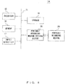
- FIG. 4 illustrates the configuration of hardware of the controller 14.
- the controller 14 is, for example, a standard computer.
- the controller 14 includes a processor 15, a memory 16, an input/output interface 17, a storage 18, and a portable recording medium driving device 19 that a portable recording medium 20 is inserted into, and these components are mutually connected by a bus 21.
- the configuration of FIG. 4 is an example of a hardware configuration of the controller 14, and the controller 14 is not limited to this configuration.
- the processor 15 is, for example, a central processing unit (CPU), a micro processing unit (MPU), a digital signal processor (DSP), or the like, and the processor 15 executes a program, and performs programmed processing.
- the memory 16 is, for example, a random access memory (RAM), and the memory 16 temporarily stores a program or data recorded in the storage 18 or the portable recording medium 20.
- the input/output interface 17 is a circuit that transmits or receives a signal to/from devices other than the controller 14 (for example, the laser 1, the photodetector 12, the turret 13, and the like).
- the storage 18 is, for example, a hard disk or a flash memory, and the storage 18 is principally used to record various types of data or programs.
- the portable recording medium driving device 19 accommodates the portable recording medium 20 such as an optical disk or a CompactFlash (registered trademark).
- the portable recording medium 20 has a role of assisting the storage 18.
- FIG. 5 is a flowchart illustrating the procedure of control processing according to this embodiment. Control processing that is performed when the controller 14 executes a program is described below in detail with reference to FIG. 5 .
- the controller 14 receives the instruction to insert or remove the optical element 8 (step S1).
- the controller 14 determines that the received instruction is an instruction to insert the optical element 8 into the optical path (step S2, YES)
- the controller 14 inserts the optical element 8 into the optical path (step S3).
- the controller 14 controls the rotation of the turret 13 in such a way that the optical element 8 is located on the optical path.
- step S3 and step S5 described later may be skipped.
- step S4 the controller 14 determines that the received instruction is an instruction to remove the optical element 8 from the optical path.
- the controller 14 removes the optical element 8 from the optical path (step S4).
- the controller 14 controls the rotation of the turret 13 in such a way that the optical element 8 is located outside the optical path.
- step S4 and step S5 described later may be skipped.
- step S6 the controller 14 changes at least one of the amplification factor of the photodetector 12 or the output of the laser 1 (step S5), and obtains a transmission image (step S6).
- step S5 is performed in order to prevent a situation in which the transmission image becomes excessively bright by removing the optical element 8 from the optical path and a situation in which the transmission image becomes excessively dark by inserting the optical element 8 into the optical path.
- the controller 14 when the optical element 8 is removed from the optical path, the controller 14 reduces the amplification factor of the photodetector 12 and/or reduces the output of the laser 1.
- the controller 14 increases the amplification factor of the photodetector 12 and/or increases the output of the laser 1. It is preferable that the controller 14 control and adjust at least one of the amplification factor of the photodetector 12 and the output of the laser 1 in such a way that the brightness of a transmission image obtained in a state in which the optical element 8 has been removed from the optical path is almost the same as the brightness of a transmission image obtained in a state in which the optical element 8 has been inserted into the optical path. Consequently, a specimen can be observed with an almost constant brightness regardless of observation magnification.
- the controller 14 adjust the brightness of a transmission image while giving a higher priority to control of the amplification factor of the photodetector 12 than control of the output of the laser 1 within a range in which an influence of noise is not excessively caused.
- a higher priority be given to control of the amplification factor of the photodetector 12 than control of the output of the laser 1 in order to suppress a change in the brightness of the fluorescence image.
- a transmission image can be obtained within a wide magnification range without switching detection lenses by inserting or removing the optical element 8 between the first surface LS1 and the image plane IP, similarly to the laser scanning microscope 100, and the transmission image can also be obtained without sacrificing a space in which a specimen is arranged. Further, in the laser scanning microscope 200, the brightness of the transmission image is automatically adjusted in accordance with insertion or removal of the optical element 8, and therefore a significant change in the brightness of an image can be suppressed.
- FIG. 6 illustrates the configuration of a laser scanning microscope 300 according to this embodiment.
- the laser scanning microscope 300 is different from the laser scanning microscope 200 in that the laser scanning microscope 300 includes a plurality of objectives (an objective 5a and an objective 5b) mounted on a revolver 22, instead of the objective 5, and that the laser scanning microscope 300 includes a controller 23 that is connected to the laser 1, the photodetector 12, the turret 13, and the revolver 22.
- the laser scanning microscope 300 is similar to the laser scanning microscope 200.
- the revolver 22 is an electric revolver that switches objectives to be used by being rotationally driven according to an instruction from the controller 23.
- the controller 23 is configured to control insertion or removal of the optical element 8 into/from the optical path in accordance with the magnification of an objective to be used and to control at least one of the amplification factor of the photodetector 12 and the output of the laser 1 in accordance with insertion or removal of the optical element 8 into/from the optical path.
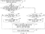
- FIG. 7 is a flowchart illustrating the procedure of control processing according to this embodiment. Control processing that is performed when the controller 23 executes a program is described below in detail with reference to FIG. 7 .
- the controller 23 receives the instruction to switch objectives, and switches objectives in accordance with the instruction (step S11).
- the controller 23 controls the rotation of the revolver 22 in such a way that an instructed objective is located on the optical path.
- the controller 23 determines whether the received instruction is an instruction to switch to an objective having a magnification lower than or equal to a prescribed magnification (step S12).
- step S12 determines that the received instruction is an instruction to switch to an objective having a magnification lower than or equal to a prescribed magnification
- step S13 determines whether the optical element 8 has been inserted into the optical path
- step S18 When the controller 23 determines that the optical element 8 has been inserted into the optical path (step S13, YES), the controller 23 obtains a transmission image (step S18).
- step S14 and step S17 are similar to step S3 and step S5 in FIG. 5 .
- step S12 determines that the received instruction is not an instruction to switch to an objective having a magnification lower than or equal to a prescribed magnification (step S12, NO)
- the controller 23 further determines whether the optical element 8 has been removed from the optical path (step S15).
- step S15 determines that the optical element 8 has been removed from the optical path
- step S15 determines that the optical element 8 has not been removed from the optical path
- step S17 the controller 23 removes the optical element 8 from the optical path (step S16), and further changes at least one of the amplification factor of the photodetector 12 and the output of the laser 1 (step S17) .
- step S18 obtains a transmission image (step S18).
- step S16 and step S17 are similar to step S4 and step S5 in FIG. 5 .
- a transmission image can be obtained within a wide magnification range without switching detection lenses by inserting or removing the optical element 8 between the first surface LS1 and the image plane IP, similarly to the laser scanning microscope 100.
- a transmission image can be obtained within a wide magnification range without sacrificing a space in which a specimen is arranged.
- the brightness of an image is automatically adjusted in accordance with insertion or removal of the optical element 8, similarly to the laser scanning microscope 200, and therefore a significant change in the brightness of the transmission image can be suppressed.
- the optical element 8 is automatically inserted or removed in accordance with an instruction to switch objectives. Accordingly, a user of a microscope can insert or remove the optical element 8 as needed by only performing a conventional operation, such as an operation to switch objectives, without being conscious of the optical element 8, and can obtain the effects above.
- FIG. 8 illustrates the configuration of a laser scanning microscope 400 according to this embodiment.
- FIG. 9 is a diagram explaining an action of an optical element 26 included in the laser scanning microscope 400.
- the laser scanning microscope 400 is different from the laser scanning microscope 100 in that the laser scanning microscope 400 includes a detection lens 24 that is an optical system formed by a plurality of lenses, instead of the detection lens 7, in that the laser scanning microscope 400 includes an aperture stop 25 that is a light shielding member arranged between the detection lens 24 and the photodetector 12, and in that the laser scanning microscope 400 includes an optical element 26 instead of the optical element 8 that is a light diffusion element.
- the laser scanning microscope 400 is similar to the laser scanning microscope 100.
- the aperture stop 25 is a diaphragm in which the size of an aperture is variable, and the aperture stop 25 is provided in or near an exit pupil position PP of the detection lens 24.
- the optical element 26 is a light deflection element that deflects a portion of a laser beam made incident on the optical element 26, and the optical element 26 is, for example, a lens chamfered near the top of an axicon lens, as illustrated in FIG. 9 .
- the optical element 26 is configure to hardly deflect light L4 made incident on a chamfered surface, and to deflect light L5 and light L6 made incident in a position deviating somewhat from the center of the base of a cone.
- the optical element 26 is arranged in a position slightly away from the exit pupil position PP of the detection lens 24 in an optical-axis direction, namely, in a position different from the exit pupil position PP of the detection lens 24, in such a way that an optical axis of the detection lens 24 passes through the center of the base of the cone of the optical element 26.
- the optical element 26 is arranged in a position that is also different from a position optically conjugate to the exit pupil position PP.
- a transmission image can be obtained within a wide magnification range without switching detection lenses, similarly to the laser scanning microscope 100.
- a transmission image can be obtained within a wide magnification range without sacrificing a space in which a specimen is arranged.
- the contrast of the transmission image can be adjusted by adjusting the size of an aperture of the aperture stop 25. Accordingly, as an example, even when a laser beam in an infrared wavelength region in which diffusion is not likely to be generated by a specimen because a wavelength is long is used, a satisfactory transmission image can be obtained by adjusting the aperture stop 25.
- the laser scanning microscope 400 may include any light deflection element that deflects a portion of a laser beam. Accordingly, the laser scanning microscope 400 may include an optical element 27 illustrated in FIG. 10 or an optical element 28 illustrated in FIG. 11 instead of the optical element 26.
- the optical element 27 is configured by replacing a curved surface in the central portion of a Fresnel lens with a plane surface.
- the optical element 28 is a diffraction grating in which a concentric pattern is formed in a portion excluding a central portion.
- the laser scanning microscope 400 can exhibit the effects above even when the laser scanning microscope 400 includes the optical element 27 or the optical element 28 instead of the optical element 26.
- the laser scanning microscope 400 may include any light shielding member that includes an aperture and partially shields an incident light flux between the detection lens 24 and the photodetector 12. Therefore, the laser scanning microscope 400 may include a light shielding member 29 illustrated in FIG. 12 , a light shielding member 30 illustrated in FIG. 13 , or a light shielding member 31 illustrated in FIG. 14 , instead of the aperture stop 25, in or near the exit pupil position PP.
- the light shielding member 29 is a diaphragm for oblique illumination that includes a light shielding unit 29a and an aperture 29b.
- the light shielding member 30 is a diaphragm that includes an eccentric aperture, and the light shielding member 30 includes a light shielding unit 30a and an aperture 30b that is formed in a position eccentric from the optical axis.
- the light shielding member 31 includes a light shielding unit 31a and an aperture 31b that is a ring-shaped slit.
- the laser scanning microscope 400 can exhibit the effects above even when the laser scanning microscope 400 includes the light shielding member 29, the light shielding member 30, or the light shielding member 31 instead of the aperture stop 25.
- the optical element 26 may be mounted on the turret provided near the exit pupil position PP, and may be inserted or removed into/from the optical path.
- the optical element that is removably arranged may be a light diffusion element that converts a laser beam into diffused light, such as a light diffusion plate or a fluorescent plate.
- the light diffusion element may be configured so as to be integrated with the light shielding member above (the aperture stop 25, the light shielding member 29, the light shielding member 30, or the light shielding member 31).
- a new member that is formed of the light diffusion element and the light shielding member above may function as a light shielding member that includes an aperture that is configured by the light diffusion element.
- the new member be removably arranged between the image plane IP and the first surface LS1.
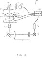
- FIG. 15 illustrates the configuration of a laser scanning microscope 500 according to this embodiment.
- the laser scanning microscope 500 is different from the laser scanning microscope 400 in that the laser scanning microscope 500 includes a turret 13 that inserts or removes the optical element 26 into/from the optical path and a controller 32 that is connected to the laser 1, the photodetector 12, the turret 13, and the aperture stop 25.
- the laser scanning microscope 500 is similar to the laser scanning microscope 400.
- the turret 13 is an electric turret that is rotationally driven according to an instruction from the controller 32.
- the controller 32 is configured to control at least one of the amplification factor of the photodetector 12 or the output of the laser 1 in accordance with insertion or removal of the optical element 26 into/from the optical path.
- the controller 32 is further configured to control the size of the aperture of the aperture stop 25 in accordance with the contrast of a scanning image (a transmission image) of a specimen that is generated according to an output from the photodetector 12.
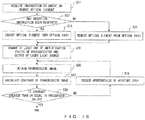
- FIG. 16 is a flowchart illustrating the procedure of control processing according to this embodiment. Control processing that is performed when the controller 32 executes a program is described below in detail with reference to FIG. 16 .
- Step S31 to step S36 are similar to step S1 to step S6 in FIG. 5 .
- the controller 32 calculates the contrast of the transmission image (step S37).
- the contrast is calculated by using an arbitrary known method.
- step S38 determines whether the calculated contrast of the transmission image is greater than or equal to a prescribed value.
- step S39 the controller 32 reduces the aperture size of the aperture stop 25 (step S39), and the processing returns to step S36.
- step S39 the controller 32 controls the aperture stop 25 in such a way that the size of the aperture of the aperture stop 25 is reduced.
- Step S36 to step S39 are repeated until the contrast of the transmission image becomes greater than or equal to the prescribed value, and the control processing is terminated when the contrast becomes greater than or equal to the prescribed value.
- a transmission image can be obtained within a wide magnification range without switching detection lenses, and the transmission image can be obtained within a wide magnification range without sacrificing a space in which a specimen is arranged, similarly to the laser scanning microscope 100.
- the brightness of an image is automatically adjusted in accordance with insertion or removal of the optical element 26, similarly to the laser scanning microscope 200, and therefore a significant change in the brightness of the transmission image can be suppressed.
- the contrast of the transmission image can be adjusted by adjusting the size of the aperture of the aperture stop 25.
- the aperture stop 25 is automatically controlled according to the contrast of the obtained transmission image, and therefore a user of a microscope can easily obtain a high-contrast image.
- FIG. 17 illustrates the configuration of a laser scanning microscope 600 according to this embodiment.
- the laser scanning microscope 600 is different from the laser scanning microscope 500 in that the laser scanning microscope 600 includes a light shielding member 29 for oblique illumination instead of the aperture stop 25 and that the laser scanning microscope 600 includes a controller 33 that is connected to the laser 1, the photodetector 12, the turret 13, and the light shielding member 29, instead of the controller 32.
- the laser scanning microscope 600 is similar to the laser scanning microscope 500.
- the controller 33 is configured to control at least one of the amplification factor of the photodetector 12 and the output of the laser 1 in accordance with insertion or removal of the optical element 26 into/from the optical path.
- the controller 33 is configured to control the rotation of the light shielding member 29 in such a way that the position of the aperture moves. Further, the controller 33 also functions as an image processing device. Specifically, the controller 33 generates a new image of a specimen from a plurality of scanning images (transmission images) that are obtained in respective states in which the positions of the aperture of the light shielding member 29 are different from each other.
- FIG. 18 is a flowchart illustrating the procedure of control processing according to this embodiment. Control processing that is performed when the controller 33 executes a program is described below in detail with reference to FIG. 18 .
- Step S41 to step S46 are similar to step S1 to step S6 in FIG. 5 .
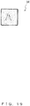
- FIG. 19 illustrates a transmission image 34 obtained in step S46.
- the transmission image 34 includes a shadow on a left-hand side of a structure in the image. This is because the light shielding member 29 is arranged as illustrated in FIG. 12 in an initial state and light enters a specimen from a right-hand side.
- step S46 When a transmission image is obtained in step S46, the controller 33 switches illumination directions (step S47).
- the controller 33 performs control such that the light shielding member 29 rotates by 180 degrees, and such that the position of the aperture 29b before rotation is symmetrical to the position after rotation with respect to the optical axis.
- FIG. 20 illustrates the light shielding member 29 after rotation.
- FIG. 21 illustrates a transmission image 35 obtained in step S48.
- the transmission image 35 includes a shadow on a right-hand side of a structure in the image, unlike the transmission image 34. This is because the light shielding member 29 is arranged as illustrated in FIG. 20 and light enters a specimen from a left-hand side.
- the controller 33 generates a new transmission image of the specimen from a plurality of scanning images obtained in respective states in which the positions of the aperture 29b are different from each other (step S49).
- an arithmetic process such as a process for calculating a difference between two images, is performed, and an image in which a contrast is emphasized is generated.
- FIG. 22 illustrates an image 36 generated in step S49.
- a transmission image can be obtained within a wide magnification range without switching detection lenses, and the transmission range can be obtained with a wide magnification range without sacrificing a space in which a specimen is arranged, similarly to the laser scanning microscope 100.
- the brightness of an image is automatically adjusted in accordance with insertion or removal of the optical element 26, similarly to the laser scanning microscope 200, and therefore a significant change in the brightness of the transmission image can be suppressed.
- an image in which a contrast is emphasized can be obtained by performing image processing.
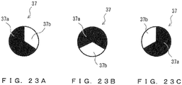
- the laser scanning microscope 600 may include a light shielding member 37 illustrated in FIG. 23A to FIG. 23C that includes a light shielding unit 37a and an aperture 37b, instead of the light shielding member 29.
- the controller 33 may rotate the light shielding member 37 by 120 degrees at a time, as illustrated in FIG. 23A to FIG. 23C , may obtain a transmission image in each state, and may generate a new transmission image in which contrast is emphasized from the three obtained transmission images.
- FIG. 24 illustrates the configuration of a laser scanning microscope 700 according to this embodiment.
- the laser scanning microscope 700 is different from the laser scanning microscope 200 in that the laser scanning microscope 700 includes a stage 39 instead of the stage 6 and that the laser scanning microscope 700 includes a controller 38 that is connected to the laser 1, the photodetector 12, the turret 13, and the stage 39, instead of the controller 14.
- the laser scanning microscope 700 is similar to the laser scanning microscope 200.
- the stage 39 is an electric stage that moves at least in the optical-axis direction of the objective 5 in accordance with an instruction from the controller 38.
- the controller 38 is configured to control at least one of the amplification factor of the photodetector 12 and the output of the laser 1 in accordance with insertion or removal of the optical element 8 into/from the optical path.
- the controller 38 controls the movement of the stage 39 in the optical-axis direction in such a way that a focal position of the detection lens 7 moves to the front or rear of the stage 39.
- the controller 38 also functions as an image processing device.
- a new transmission image of a specimen is generated from a plurality of scanning images (transmission images) that are respectively obtained in a state in which the focal position of the detection lens 7 is located on a front side of the stage 39 (namely, a front-focus state) and a state in which the focal position of the detection lens 7 is located on a rear side of the stage 39 (namely, a rear-focus state).
- FIG. 25 is a flowchart illustrating the procedure of control processing according to this embodiment. Control processing that is performed when the controller 38 executes a program is described below in detail with reference to FIG. 25 .
- Step S51 to step S55 are similar to step S1 to step S5 in FIG. 5 .
- the controller 38 moves the stage 39 in a front-focus position (step S56), and obtains a transmission image in the front-focus state (step S57).
- the controller 38 moves the stage 39 in a rear-focus position (step S58), and obtains a transmission image in the rear-focus state (step S59).
- controller 38 generates a new image of a specimen in which contrast is emphasized from the two transmission images obtained in the front-focus state and the rear-focus state (step S60), and terminates the control processing.
- a transmission image can be obtained within a wide magnification range without switching detection lenses, and the transmission image can be obtained within a wide magnification range without sacrificing a space in which a specimen is arranged, similarly to the laser scanning microscope 100.
- the brightness of an image is automatically adjusted according to insertion or removal of the optical element 8, similarly to the laser scanning microscope 200, and therefore a significant change in the brightness of the transmission image can be suppressed.
- an image in which contrast is emphasized can be obtained by performing image processing, similarly to the laser scanning microscope 600.
Landscapes
- Physics & Mathematics (AREA)
- General Physics & Mathematics (AREA)
- Analytical Chemistry (AREA)
- Chemical & Material Sciences (AREA)
- Optics & Photonics (AREA)
- Health & Medical Sciences (AREA)
- Biochemistry (AREA)
- Nuclear Medicine, Radiotherapy & Molecular Imaging (AREA)
- Life Sciences & Earth Sciences (AREA)
- General Health & Medical Sciences (AREA)
- Immunology (AREA)
- Pathology (AREA)
- Spectroscopy & Molecular Physics (AREA)
- General Engineering & Computer Science (AREA)
- Computer Vision & Pattern Recognition (AREA)
- Engineering & Computer Science (AREA)
- Microscoopes, Condenser (AREA)
- Investigating, Analyzing Materials By Fluorescence Or Luminescence (AREA)
Abstract
Description
- Disclosure of the present invention relates to a laser scanning microscope, and a laser scanning microscope control method.
- Conventionally, a laser scanning microscope is known, for example, that includes a detection lens that faces an objective with a biological specimen interposed between the detection lens and the objective, and a photodetector that detects light that passes through the biological specimen and is condensed by the detection lens (see Japanese Laid-Open Patent Publication No.
2010-102264 - By employing the laser scanning microscope above, a transmission image that enables the shape of a cell in the biological specimen to be grasped, in addition to a fluorescence image, can be obtained by scanning the biological specimen once. In addition, vital phenomena that occur in the cell can be observed better by displaying the fluorescence image over the transmission image.
- In recent years, microscopes have been requested to be capable of observing interactions between cells in addition to phenomena within a cell. Accordingly, laser scanning microscopes have been requested to cope with a wider magnification range than before, and in particular, a wide magnification range including a very low magnification that is lower than 10 times.
- Generally, in laser scanning microscopes, a fluorescence image can be obtained within a wide magnification range by switching and using objectives having magnifications different from each other. In addition, a transmission image can also be obtained within a wide magnification range by switching detection lenses according to the magnification of the objective.
- In consideration of work burdens on a user, a cost, and the like, it is desirable that the same detection lens be used within a wide magnification range without switching detection lenses, when transmission images are obtained. Accordingly, a laser scanning microscope that uses a detection lens having a relatively large lens diameter within a wide magnification range in order to suppress vignetting of off-axis light in the detection lens, a laser scanning microscope that includes an auxiliary lens that can be inserted or removed on an object side of a detection lens, and the like have been proposed.
- However, when a detection lens is attempted to cope with observation at a very low magnification, the lens diameter of the detection lens greatly increases. In addition, even when the lens diameter of the detection lens increases, there is a limit to suppression of vignetting that is generated on a side closer to a photodetector than the detection lens. Accordingly, it is difficult to widen a magnification range to a lower magnification than before only by increasing the lens diameter of the detection lens. Further, in a configuration in which an auxiliary lens is inserted or removed on an object side of the detection lens, a space into which the auxiliary lens is inserted is required. Therefore, a space in which a biological specimen is arranged is reduced, and this results in restriction in the size of the biological specimen. Furthermore, the efficiency of various tasks performed on a stage is reduced.
- In view of the circumstances above, it is an object in one aspect of the present invention to provide a technology for obtaining a transmission image within a wide magnification range without sacrificing a space in which a specimen is arranged and switching detection lenses.
- A laser scanning microscope in one aspect of the present invention includes: an objective that irradiates a specimen with a laser beam; a detection lens that condenses the laser beam that passes through the specimen, the detection lens being arranged so as to face the objective with the specimen interposed between the detection lens and the objective; an optical element that is removably arranged between an image plane on which the detection lens forms an image of the specimen and a first surface that is a lens surface closest to the specimen of the detection lens, the optical element converting the laser beam made incident on the optical element into diffused light or deflecting a portion of the laser beam made incident on the optical element; and a photodetector that detects detection light emitted from the optical element arranged between the image plane and the first surface to the image plane.
- A control method of a laser scanning microscope in another aspect of the present invention includes: controlling insertion or removal of an optical element between an image plane on which a detection lens forms an image of a specimen and a first surface that is a lens surface closest to the specimen of the detection lens in accordance with a magnification of an objective that irradiates the specimen with a laser beam, the optical element converting the laser beam into diffused light or deflecting a portion of the laser beam, the detection lens being arranged so as to face the objective with the specimen interposed between the detection lens and the objective; and controlling at least one of an amplification factor of a photodetector and an output of a laser light source in accordance with the insertion or removal of the optical element, the photodetector detecting detection light emitted from the optical element to the image plane, the laser light source emitting the laser beam.
- According to an aspect of the present invention, a transmission image can be obtained within a wide magnification range without sacrificing a space in which a specimen is arranged and switching detection lenses.
- The present invention will be more apparent from the following detailed description when the accompanying drawings are referenced.
-
FIG. 1 illustrates the configuration of alaser scanning microscope 100 according to a first embodiment. -
FIG. 2 is a diagram explaining an action of anoptical element 8. -
FIG. 3 illustrates the configuration of alaser scanning microscope 200 according to a second embodiment. -
FIG. 4 illustrates the configuration of hardware of acontroller 14. -
FIG. 5 is a flowchart illustrating the procedure of control processing according to the second embodiment. -
FIG. 6 illustrates the configuration of alaser scanning microscope 300 according to a third embodiment. -
FIG. 7 is a flowchart illustrating the procedure of control processing according to the third embodiment. -
FIG. 8 illustrates the configuration of alaser scanning microscope 400 according to a fourth embodiment. -
FIG. 9 is a diagram explaining an action of anoptical element 26. -
FIG. 10 illustrates anoptical element 27. -
FIG. 11 illustrates anoptical element 28. -
FIG. 12 illustrates alight shielding member 29. -
FIG. 13 illustrates alight shielding member 30. -
FIG. 14 illustrates alight shielding member 31. -
FIG. 15 illustrates the configuration of alaser scanning microscope 500 according to a fifth embodiment. -
FIG. 16 is a flowchart illustrating the procedure of control processing according to the fifth embodiment. -
FIG. 17 illustrates the configuration of alaser scanning microscope 600 according to a sixth embodiment. -
FIG. 18 is a flowchart illustrating the procedure of control processing according to the sixth embodiment. -
FIG. 19 illustrates animage 34 of a specimen to which oblique illumination is applied. -
FIG. 20 illustrates thelight shielding member 29, and illustrates a situation in which the position of an opening 29a has been changed from the position inFIG. 12 . -
FIG. 21 illustrates anotherimage 35 of the specimen to which oblique illumination is applied. -
FIG. 22 illustrates animage 36 that is newly generated from theimage 34 ofFIG. 19 and theimage 35 ofFIG. 21 . -
FIG. 23A to FIG. 23C illustrate alight shielding member 37. -
FIG. 24 illustrates the configuration of alaser scanning microscope 700 according to a seventh embodiment. -
FIG. 25 is a flowchart illustrating the procedure of control processing according to the seventh embodiment. -
FIG. 1 illustrates the configuration of alaser scanning microscope 100 according to this embodiment.FIG. 2 is a diagram explaining an action of anoptical element 8 included in thelaser scanning microscope 100. This embodiment is described below by using a case in which thelaser scanning microscope 100 is used to observe a biological specimen as an example. - The
laser scanning microscope 100 includes alaser 1 that emits a laser beam. Thelaser scanning microscope 100 further includes ascanner 2, a relayoptical system 3, amirror 4, and an objective 5 on an illumination light path from thelaser 1 to astage 6. - The
laser 1 is a laser light source that emits a laser beam that excites a specimen. Thescanner 2 is a two-dimensional scanner that scans a specimen arranged on thestage 6 in a direction orthogonal to an optical axis of theobjective 5 by changing a direction in which the laser beam is deflected. Thescanner 2 includes, for example, a resonant scanner and a galvanometer mirror. The relayoptical system 3 is an optical system that projects an image of thescanner 2 in or near a pupil position of theobjective 5. The objective 5 is an infinity-corrected objective, and the objective 5 irradiates the specimen arranged on thestage 6 with a laser beam. In thelaser scanning microscope 100, objectives having various magnifications are switched and used by using a not-illustrated revolver or the like. - The
laser scanning microscope 100 includes aphotodetector 12 for transmission detection. Thelaser scanning microscope 100 further includes adetection lens 7, anoptical element 8, afield stop 9, amirror 10, and a relayoptical system 11 on an optical path from thestage 6 to thephotodetector 12. - Both the
mirror 4 and themirror 10 described above may be dichroic mirrors, or may be half mirrors. In these cases, another detection optical system and another illumination optical system can be arranged respectively on transmitted light paths of themirror 4 and themirror 10 along an optical-axis direction of theobjective 5. - The
detection lens 7 is a lens that condenses a laser beam that has passed through the specimen, and thedetection lens 7 is arranged so as to face theobjective 5 with the stage 6 (or the specimen arranged on the stage 6) interposed between thedetection lens 7 and theobjective 5. Theoptical element 8 is a light diffusion element that converts a laser beam made incident on theoptical element 8 into diffused light, and theoptical element 8 is a light diffusion plate in this example. Theoptical element 8 is removably arranged between an image plane IP on which thedetection lens 7 forms an image of the specimen and a first surface LS1 that is a lens surface closest to the specimen of thedetection lens 7. - The
field stop 9 is provided on the image plane IP that is optically conjugate to a specimen surface (a surface of the stage 6). The relayoptical system 11 is a relay optical system that projects an exit pupil of thedetection lens 7 onto thephotodetector 12, and the relayoptical system 11 is arranged between theoptical element 8 that is arranged between the image plane IP and the first surface LS1, and thephotodetector 12. Thephotodetector 12 is a photodetector that outputs a signal according to an intensity of a detected laser beam, and thephotodetector 12 is, for example, a photomultiplier tube (PMT). - In the
laser scanning microscope 100 that is configured as described above, a position in which the laser beam is applied to the specimen changes according to a direction in which thescanner 2 deflects the laser beam. The laser beam that has passed through the specimen enters thephotodetector 12 regardless of an irradiation position, unless vignetting is generated on the optical path. Accordingly, a scanning image of the specimen can be obtained by obtaining luminance data according to a signal that is output from thephotodetector 12 in each of the irradiation positions of the laser beam, and two-dimensionally mapping respective pieces of luminance data according to the irradiation positions. This scanning image is an image obtained by detecting light that has passed through the specimen, and therefore the scanning image is also referred to as a transmission image. - Meanwhile, in the
laser scanning microscope 100, as the laser beam condensed by thedetection lens 7 moves farther away from an exit pupil position of thedetection lens 7 after having passed through the exit pupil position, the laser beam further deviates from the optical axis. This tendency becomes remarkable because, as a lower-magnification objective having a wider illumination range (field of view) is used, a laser beam from a position away from the optical axis on the specimen passes through the exit pupil position at a sharper angle. Accordingly, when the magnification of an objective to be used is reduced (for example, when the magnification becomes lower than or equal to a certain magnification), vignetting is generated in a configuration located at a rear stage of the detection lens 7 (for example, thefield stop 9 or the relay optical system 11). Therefore, a transmission image is likely to be dark in a peripheral portion of a field of view. - Accordingly, in the
laser scanning microscope 100, a user inserts or removes theoptical element 8 between the first surface LS1 and the image plane IP in accordance with a situation. Typically, when the magnification of an objective to be used is low, theoptical element 8 is arranged on the optical path. When the transmission image is dark in the peripheral portion of the field of view, theoptical element 8 may be arranged on the optical path. - Consequently, as illustrated in
FIG. 2 , light L1 from the peripheral portion of the field of view that is shielded by thefield stop 9 if theoptical element 8 is not inserted into the optical path is converted into diffused light L2 by theoptical element 8, and a portion of the diffused light L2 passes through thefield stop 9. Therefore, deficiency in a peripheral light amount can be suppressed. When the magnification of an objective to be used is high, theoptical element 8 is arranged outside the optical path. Consequently, an amount of detection light can be prevented from decreasing due to unnecessary diffusion in theoptical element 8. - Accordingly, by employing the
laser scanning microscope 100, a transmission image can be obtained within a wide magnification range without switching detection lenses by inserting or removing theoptical element 8 into/from the optical path as needed. A transmission image can be obtained within a wide magnification range without sacrificing a space in which a specimen is arranged, in particular, by inserting or removing theoptical element 8 between the first surface LS1 and the image plane IP. - The
laser scanning microscope 100 may include an optical system and a photodetector for detecting fluorescence that is emitted from the specimen to theobjective 5 due to irradiation with a laser beam, but this is not illustrated inFIG. 1 . In this case, a dichroic mirror is used, for example, as themirror 4. Consequently, thelaser scanning microscope 100 can obtain a fluorescence image in addition to a transmission image by performing one scanning. - In addition, the
laser scanning microscope 100 may include an illumination unit that illuminates the specimen from a side of thedetection lens 7, but this is not illustrated inFIG. 1 . In this case, thedetection lens 7 may be a condenser lens, and thefield stop 9 is used to restrict an illumination range. In addition, a half mirror is used, for example, as themirror 10. - An example in which the
photodetector 12 detects a laser beam has been described above, but light detected by thephotodetector 12 is not limited to the laser beam. Theoptical element 8 may be any light diffusion element that converts a laser beam made incident on theoptical element 8 into diffused light. Therefore, theoptical element 8 may be, for example, a fluorescent plate that emits fluorescence upon incidence of a laser beam, or may be an upconversion light-emitting element that emits light having a wavelength shorter than the wavelength of a laser beam upon incidence of the laser beam. Namely, theoptical element 8 may be an optical element that converts a laser beam into light having a different wavelength and emits the light, and thephotodetector 12 may detect light that is emitted from theoptical element 8 to the image plane IP (hereinafter referred to as detection light). The detection light may be a laser beam, light having a wavelength longer than the wavelength of the laser beam, or light having a wavelength shorter than the wavelength of the laser beam. -
FIG. 3 illustrates the configuration of alaser scanning microscope 200 according to this embodiment. Thelaser scanning microscope 200 is different from thelaser scanning microscope 100 in that thelaser scanning microscope 200 includes aturret 13 that inserts or removes theoptical element 8 into/from the optical path and acontroller 14 that is connected to thelaser 1, thephotodetector 12, and theturret 13. In the other respects, thelaser scanning microscope 200 is similar to thelaser scanning microscope 100. Theturret 13 is an electric turret that is rotationally driven according to an instruction from thecontroller 14. Thecontroller 14 is configured to control at least one of an amplification factor of thephotodetector 12 and an output of thelaser 1 in accordance with insertion or removal of theoptical element 8 into/from the optical path. In addition, thecontroller 14 is configured to control insertion or removal of theoptical element 8 into/from the optical path. -
FIG. 3 illustrates theturret 13 as a mechanism that inserts or removes theoptical element 8 into/from the optical path, but the mechanism that inserts or removes theoptical element 8 into/from the optical path is not particularly limited, and an arbitrary mechanism can be employed. As an example, a drive mechanism that slidably inserts or removes theoptical element 8 may be employed instead of theturret 13. -
FIG. 4 illustrates the configuration of hardware of thecontroller 14. Thecontroller 14 is, for example, a standard computer. Thecontroller 14 includes aprocessor 15, amemory 16, an input/output interface 17, astorage 18, and a portable recordingmedium driving device 19 that aportable recording medium 20 is inserted into, and these components are mutually connected by abus 21. The configuration ofFIG. 4 is an example of a hardware configuration of thecontroller 14, and thecontroller 14 is not limited to this configuration. - The
processor 15 is, for example, a central processing unit (CPU), a micro processing unit (MPU), a digital signal processor (DSP), or the like, and theprocessor 15 executes a program, and performs programmed processing. Thememory 16 is, for example, a random access memory (RAM), and thememory 16 temporarily stores a program or data recorded in thestorage 18 or theportable recording medium 20. - The input/
output interface 17 is a circuit that transmits or receives a signal to/from devices other than the controller 14 (for example, thelaser 1, thephotodetector 12, theturret 13, and the like). Thestorage 18 is, for example, a hard disk or a flash memory, and thestorage 18 is principally used to record various types of data or programs. The portable recordingmedium driving device 19 accommodates theportable recording medium 20 such as an optical disk or a CompactFlash (registered trademark). Theportable recording medium 20 has a role of assisting thestorage 18. -
FIG. 5 is a flowchart illustrating the procedure of control processing according to this embodiment. Control processing that is performed when thecontroller 14 executes a program is described below in detail with reference toFIG. 5 . - First, when a user issues an instruction to insert or remove the
optical element 8 by using a not-illustrated input device, thecontroller 14 receives the instruction to insert or remove the optical element 8 (step S1). When thecontroller 14 determines that the received instruction is an instruction to insert theoptical element 8 into the optical path (step S2, YES), thecontroller 14 inserts theoptical element 8 into the optical path (step S3). Here, thecontroller 14 controls the rotation of theturret 13 in such a way that theoptical element 8 is located on the optical path. When theoptical element 8 is already located on the optical path, step S3 and step S5 described later may be skipped. - When the
controller 14 determines that the received instruction is an instruction to remove theoptical element 8 from the optical path (step S2, NO), thecontroller 14 removes theoptical element 8 from the optical path (step S4). Here, thecontroller 14 controls the rotation of theturret 13 in such a way that theoptical element 8 is located outside the optical path. When theoptical element 8 is already located outside the optical path, step S4 and step S5 described later may be skipped. - When the process of step S3 or step S4 is finished, the
controller 14 changes at least one of the amplification factor of thephotodetector 12 or the output of the laser 1 (step S5), and obtains a transmission image (step S6). - The process of step S5 is performed in order to prevent a situation in which the transmission image becomes excessively bright by removing the
optical element 8 from the optical path and a situation in which the transmission image becomes excessively dark by inserting theoptical element 8 into the optical path. - Specifically, when the
optical element 8 is removed from the optical path, thecontroller 14 reduces the amplification factor of thephotodetector 12 and/or reduces the output of thelaser 1. When theoptical element 8 is inserted into the optical path, thecontroller 14 increases the amplification factor of thephotodetector 12 and/or increases the output of thelaser 1. It is preferable that thecontroller 14 control and adjust at least one of the amplification factor of thephotodetector 12 and the output of thelaser 1 in such a way that the brightness of a transmission image obtained in a state in which theoptical element 8 has been removed from the optical path is almost the same as the brightness of a transmission image obtained in a state in which theoptical element 8 has been inserted into the optical path. Consequently, a specimen can be observed with an almost constant brightness regardless of observation magnification. - Further, assume a case in which a damage-susceptible biological specimen is a target to be observed. It is preferable that the
controller 14 adjust the brightness of a transmission image while giving a higher priority to control of the amplification factor of thephotodetector 12 than control of the output of thelaser 1 within a range in which an influence of noise is not excessively caused. In particular, when a fluorescence image is obtained together with the transmission image, it is further preferable that a higher priority be given to control of the amplification factor of thephotodetector 12 than control of the output of thelaser 1 in order to suppress a change in the brightness of the fluorescence image. - Also by employing the
laser scanning microscope 200, a transmission image can be obtained within a wide magnification range without switching detection lenses by inserting or removing theoptical element 8 between the first surface LS1 and the image plane IP, similarly to thelaser scanning microscope 100, and the transmission image can also be obtained without sacrificing a space in which a specimen is arranged. Further, in thelaser scanning microscope 200, the brightness of the transmission image is automatically adjusted in accordance with insertion or removal of theoptical element 8, and therefore a significant change in the brightness of an image can be suppressed. -
FIG. 6 illustrates the configuration of alaser scanning microscope 300 according to this embodiment. Thelaser scanning microscope 300 is different from thelaser scanning microscope 200 in that thelaser scanning microscope 300 includes a plurality of objectives (an objective 5a and an objective 5b) mounted on arevolver 22, instead of theobjective 5, and that thelaser scanning microscope 300 includes acontroller 23 that is connected to thelaser 1, thephotodetector 12, theturret 13, and therevolver 22. In the other respects, thelaser scanning microscope 300 is similar to thelaser scanning microscope 200. Therevolver 22 is an electric revolver that switches objectives to be used by being rotationally driven according to an instruction from thecontroller 23. Thecontroller 23 is configured to control insertion or removal of theoptical element 8 into/from the optical path in accordance with the magnification of an objective to be used and to control at least one of the amplification factor of thephotodetector 12 and the output of thelaser 1 in accordance with insertion or removal of theoptical element 8 into/from the optical path. -
FIG. 7 is a flowchart illustrating the procedure of control processing according to this embodiment. Control processing that is performed when thecontroller 23 executes a program is described below in detail with reference toFIG. 7 . - First, when a user issues an instruction to switch objectives by using a not-illustrated input device, the
controller 23 receives the instruction to switch objectives, and switches objectives in accordance with the instruction (step S11). Here, thecontroller 23 controls the rotation of therevolver 22 in such a way that an instructed objective is located on the optical path. Then, thecontroller 23 determines whether the received instruction is an instruction to switch to an objective having a magnification lower than or equal to a prescribed magnification (step S12). - When the
controller 23 determines that the received instruction is an instruction to switch to an objective having a magnification lower than or equal to a prescribed magnification (step S12, YES), thecontroller 23 further determines whether theoptical element 8 has been inserted into the optical path (step S13). - When the
controller 23 determines that theoptical element 8 has been inserted into the optical path (step S13, YES), thecontroller 23 obtains a transmission image (step S18). When thecontroller 23 determines that theoptical element 8 has not been inserted into the optical path (step S13, NO), thecontroller 23 inserts theoptical element 8 into the optical path (step S14), and further changes at least one of the amplification factor of thephotodetector 12 and the output of the laser 1 (step S17). Then, thecontroller 23 obtains a transmission image (step S18). Note that step S14 and step S17 are similar to step S3 and step S5 inFIG. 5 . - When the
controller 23 determines that the received instruction is not an instruction to switch to an objective having a magnification lower than or equal to a prescribed magnification (step S12, NO), thecontroller 23 further determines whether theoptical element 8 has been removed from the optical path (step S15). - When the
controller 23 determines that theoptical element 8 has been removed from the optical path (step S15, YES), thecontroller 23 obtains a transmission image (step S18). When thecontroller 23 determines that theoptical element 8 has not been removed from the optical path (step S15, NO), thecontroller 23 removes theoptical element 8 from the optical path (step S16), and further changes at least one of the amplification factor of thephotodetector 12 and the output of the laser 1 (step S17) . Then, thecontroller 23 obtains a transmission image (step S18). Note that step S16 and step S17 are similar to step S4 and step S5 inFIG. 5 . - Also by employing the
laser scanning microscope 300, a transmission image can be obtained within a wide magnification range without switching detection lenses by inserting or removing theoptical element 8 between the first surface LS1 and the image plane IP, similarly to thelaser scanning microscope 100. In addition, a transmission image can be obtained within a wide magnification range without sacrificing a space in which a specimen is arranged. Further, the brightness of an image is automatically adjusted in accordance with insertion or removal of theoptical element 8, similarly to thelaser scanning microscope 200, and therefore a significant change in the brightness of the transmission image can be suppressed. Furthermore, in thelaser scanning microscope 300, theoptical element 8 is automatically inserted or removed in accordance with an instruction to switch objectives. Accordingly, a user of a microscope can insert or remove theoptical element 8 as needed by only performing a conventional operation, such as an operation to switch objectives, without being conscious of theoptical element 8, and can obtain the effects above. -
FIG. 8 illustrates the configuration of alaser scanning microscope 400 according to this embodiment.FIG. 9 is a diagram explaining an action of anoptical element 26 included in thelaser scanning microscope 400. Thelaser scanning microscope 400 is different from thelaser scanning microscope 100 in that thelaser scanning microscope 400 includes adetection lens 24 that is an optical system formed by a plurality of lenses, instead of thedetection lens 7, in that thelaser scanning microscope 400 includes anaperture stop 25 that is a light shielding member arranged between thedetection lens 24 and thephotodetector 12, and in that thelaser scanning microscope 400 includes anoptical element 26 instead of theoptical element 8 that is a light diffusion element. In the other respects, thelaser scanning microscope 400 is similar to thelaser scanning microscope 100. - The
aperture stop 25 is a diaphragm in which the size of an aperture is variable, and theaperture stop 25 is provided in or near an exit pupil position PP of thedetection lens 24. Theoptical element 26 is a light deflection element that deflects a portion of a laser beam made incident on theoptical element 26, and theoptical element 26 is, for example, a lens chamfered near the top of an axicon lens, as illustrated inFIG. 9 . Theoptical element 26 is configure to hardly deflect light L4 made incident on a chamfered surface, and to deflect light L5 and light L6 made incident in a position deviating somewhat from the center of the base of a cone. - In the
laser scanning microscope 400, theoptical element 26 is arranged in a position slightly away from the exit pupil position PP of thedetection lens 24 in an optical-axis direction, namely, in a position different from the exit pupil position PP of thedetection lens 24, in such a way that an optical axis of thedetection lens 24 passes through the center of the base of the cone of theoptical element 26. By arranging as described above, off-axis light in which vignetting is likely to be generated by thefield stop 9, the relayoptical system 11, or the like can be deflected, while suppressing deflection of on-axis light as much as possible. In the case of a configuration in which the pupil is relayed before thephotodetector 12, theoptical element 26 is arranged in a position that is also different from a position optically conjugate to the exit pupil position PP. - Also by employing the
laser scanning microscope 400, a transmission image can be obtained within a wide magnification range without switching detection lenses, similarly to thelaser scanning microscope 100. In addition, a transmission image can be obtained within a wide magnification range without sacrificing a space in which a specimen is arranged. Further, in thelaser scanning microscope 400, the contrast of the transmission image can be adjusted by adjusting the size of an aperture of theaperture stop 25. Accordingly, as an example, even when a laser beam in an infrared wavelength region in which diffusion is not likely to be generated by a specimen because a wavelength is long is used, a satisfactory transmission image can be obtained by adjusting theaperture stop 25. - In this embodiment, an example in which the
laser scanning microscope 400 includes theoptical element 26 has been described, but thelaser scanning microscope 400 may include any light deflection element that deflects a portion of a laser beam. Accordingly, thelaser scanning microscope 400 may include anoptical element 27 illustrated inFIG. 10 or anoptical element 28 illustrated inFIG. 11 instead of theoptical element 26. Theoptical element 27 is configured by replacing a curved surface in the central portion of a Fresnel lens with a plane surface. Theoptical element 28 is a diffraction grating in which a concentric pattern is formed in a portion excluding a central portion. Thelaser scanning microscope 400 can exhibit the effects above even when thelaser scanning microscope 400 includes theoptical element 27 or theoptical element 28 instead of theoptical element 26. - In this embodiment, an example in which the
laser scanning microscope 400 includes theaperture stop 25 has been described, but thelaser scanning microscope 400 may include any light shielding member that includes an aperture and partially shields an incident light flux between thedetection lens 24 and thephotodetector 12. Therefore, thelaser scanning microscope 400 may include alight shielding member 29 illustrated inFIG. 12 , alight shielding member 30 illustrated inFIG. 13 , or alight shielding member 31 illustrated inFIG. 14 , instead of theaperture stop 25, in or near the exit pupil position PP. Thelight shielding member 29 is a diaphragm for oblique illumination that includes alight shielding unit 29a and anaperture 29b. Thelight shielding member 30 is a diaphragm that includes an eccentric aperture, and thelight shielding member 30 includes alight shielding unit 30a and anaperture 30b that is formed in a position eccentric from the optical axis. Thelight shielding member 31 includes alight shielding unit 31a and anaperture 31b that is a ring-shaped slit. Thelaser scanning microscope 400 can exhibit the effects above even when thelaser scanning microscope 400 includes thelight shielding member 29, thelight shielding member 30, or thelight shielding member 31 instead of theaperture stop 25. - In addition, when the
laser scanning microscope 400 includes a turret near the exit pupil position PP, theoptical element 26 may be mounted on the turret provided near the exit pupil position PP, and may be inserted or removed into/from the optical path. - Further, an example has been described in which an optical element that is removably arranged between the image plane IP and the first surface SL1 deflects a portion of a laser beam, but the optical element that is removably arranged may be a light diffusion element that converts a laser beam into diffused light, such as a light diffusion plate or a fluorescent plate. Furthermore, the light diffusion element may be configured so as to be integrated with the light shielding member above (the
aperture stop 25, thelight shielding member 29, thelight shielding member 30, or the light shielding member 31). Namely, a new member that is formed of the light diffusion element and the light shielding member above may function as a light shielding member that includes an aperture that is configured by the light diffusion element. In this case, it is preferable that the new member be removably arranged between the image plane IP and the first surface LS1. -
FIG. 15 illustrates the configuration of alaser scanning microscope 500 according to this embodiment. Thelaser scanning microscope 500 is different from thelaser scanning microscope 400 in that thelaser scanning microscope 500 includes aturret 13 that inserts or removes theoptical element 26 into/from the optical path and acontroller 32 that is connected to thelaser 1, thephotodetector 12, theturret 13, and theaperture stop 25. In the other respects, thelaser scanning microscope 500 is similar to thelaser scanning microscope 400. Theturret 13 is an electric turret that is rotationally driven according to an instruction from thecontroller 32. Thecontroller 32 is configured to control at least one of the amplification factor of thephotodetector 12 or the output of thelaser 1 in accordance with insertion or removal of theoptical element 26 into/from the optical path. Thecontroller 32 is further configured to control the size of the aperture of theaperture stop 25 in accordance with the contrast of a scanning image (a transmission image) of a specimen that is generated according to an output from thephotodetector 12. -
FIG. 16 is a flowchart illustrating the procedure of control processing according to this embodiment. Control processing that is performed when thecontroller 32 executes a program is described below in detail with reference toFIG. 16 . - Step S31 to step S36 are similar to step S1 to step S6 in
FIG. 5 . When a transmission image is obtained in step S36, thecontroller 32 calculates the contrast of the transmission image (step S37). The contrast is calculated by using an arbitrary known method. - Then, the
controller 32 determines whether the calculated contrast of the transmission image is greater than or equal to a prescribed value (step S38). When thecontroller 32 determines that the contrast is smaller than the prescribed value, thecontroller 32 reduces the aperture size of the aperture stop 25 (step S39), and the processing returns to step S36. In step S39, thecontroller 32 controls theaperture stop 25 in such a way that the size of the aperture of theaperture stop 25 is reduced. - Step S36 to step S39 are repeated until the contrast of the transmission image becomes greater than or equal to the prescribed value, and the control processing is terminated when the contrast becomes greater than or equal to the prescribed value.
- Also by employing the
laser scanning microscope 500, a transmission image can be obtained within a wide magnification range without switching detection lenses, and the transmission image can be obtained within a wide magnification range without sacrificing a space in which a specimen is arranged, similarly to thelaser scanning microscope 100. In addition, in thelaser scanning microscope 500, the brightness of an image is automatically adjusted in accordance with insertion or removal of theoptical element 26, similarly to thelaser scanning microscope 200, and therefore a significant change in the brightness of the transmission image can be suppressed. Further, in thelaser scanning microscope 500, the contrast of the transmission image can be adjusted by adjusting the size of the aperture of theaperture stop 25. Therefore, as an example, even when a laser beam in an infrared wavelength region in which a wavelength is long and diffusion is not likely to be generated by a specimen is used, a satisfactory transmission image can be obtained by adjusting theaperture stop 25. Furthermore, in thelaser scanning microscope 500, theaperture stop 25 is automatically controlled according to the contrast of the obtained transmission image, and therefore a user of a microscope can easily obtain a high-contrast image. -
FIG. 17 illustrates the configuration of alaser scanning microscope 600 according to this embodiment. Thelaser scanning microscope 600 is different from thelaser scanning microscope 500 in that thelaser scanning microscope 600 includes alight shielding member 29 for oblique illumination instead of theaperture stop 25 and that thelaser scanning microscope 600 includes acontroller 33 that is connected to thelaser 1, thephotodetector 12, theturret 13, and thelight shielding member 29, instead of thecontroller 32. In the other respects, thelaser scanning microscope 600 is similar to thelaser scanning microscope 500. Thecontroller 33 is configured to control at least one of the amplification factor of thephotodetector 12 and the output of thelaser 1 in accordance with insertion or removal of theoptical element 26 into/from the optical path. In addition, thecontroller 33 is configured to control the rotation of thelight shielding member 29 in such a way that the position of the aperture moves. Further, thecontroller 33 also functions as an image processing device. Specifically, thecontroller 33 generates a new image of a specimen from a plurality of scanning images (transmission images) that are obtained in respective states in which the positions of the aperture of thelight shielding member 29 are different from each other. -
FIG. 18 is a flowchart illustrating the procedure of control processing according to this embodiment. Control processing that is performed when thecontroller 33 executes a program is described below in detail with reference toFIG. 18 . - Step S41 to step S46 are similar to step S1 to step S6 in
FIG. 5 .FIG. 19 illustrates atransmission image 34 obtained in step S46. Thetransmission image 34 includes a shadow on a left-hand side of a structure in the image. This is because thelight shielding member 29 is arranged as illustrated inFIG. 12 in an initial state and light enters a specimen from a right-hand side. - When a transmission image is obtained in step S46, the
controller 33 switches illumination directions (step S47). Here, thecontroller 33 performs control such that thelight shielding member 29 rotates by 180 degrees, and such that the position of theaperture 29b before rotation is symmetrical to the position after rotation with respect to the optical axis.FIG. 20 illustrates thelight shielding member 29 after rotation. - Then, the
controller 33 obtains a transmission image again (step S48).FIG. 21 illustrates atransmission image 35 obtained in step S48. Thetransmission image 35 includes a shadow on a right-hand side of a structure in the image, unlike thetransmission image 34. This is because thelight shielding member 29 is arranged as illustrated inFIG. 20 and light enters a specimen from a left-hand side. - Finally, the
controller 33 generates a new transmission image of the specimen from a plurality of scanning images obtained in respective states in which the positions of theaperture 29b are different from each other (step S49). Here, as an example, an arithmetic process, such as a process for calculating a difference between two images, is performed, and an image in which a contrast is emphasized is generated.FIG. 22 illustrates animage 36 generated in step S49. - Also, by employing the
laser scanning microscope 600, a transmission image can be obtained within a wide magnification range without switching detection lenses, and the transmission range can be obtained with a wide magnification range without sacrificing a space in which a specimen is arranged, similarly to thelaser scanning microscope 100. In addition, in thelaser scanning microscope 600, the brightness of an image is automatically adjusted in accordance with insertion or removal of theoptical element 26, similarly to thelaser scanning microscope 200, and therefore a significant change in the brightness of the transmission image can be suppressed. Further, in thelaser scanning microscope 600, an image in which a contrast is emphasized can be obtained by performing image processing. - In this embodiment, an example in which the
laser scanning microscope 600 includes thelight shielding member 29 has been described, but thelaser scanning microscope 600 may include alight shielding member 37 illustrated inFIG. 23A to FIG. 23C that includes alight shielding unit 37a and anaperture 37b, instead of thelight shielding member 29. In this case, thecontroller 33 may rotate thelight shielding member 37 by 120 degrees at a time, as illustrated inFIG. 23A to FIG. 23C , may obtain a transmission image in each state, and may generate a new transmission image in which contrast is emphasized from the three obtained transmission images. -
FIG. 24 illustrates the configuration of alaser scanning microscope 700 according to this embodiment. Thelaser scanning microscope 700 is different from thelaser scanning microscope 200 in that thelaser scanning microscope 700 includes astage 39 instead of thestage 6 and that thelaser scanning microscope 700 includes acontroller 38 that is connected to thelaser 1, thephotodetector 12, theturret 13, and thestage 39, instead of thecontroller 14. In the other respects, thelaser scanning microscope 700 is similar to thelaser scanning microscope 200. Thestage 39 is an electric stage that moves at least in the optical-axis direction of theobjective 5 in accordance with an instruction from thecontroller 38. Thecontroller 38 is configured to control at least one of the amplification factor of thephotodetector 12 and the output of thelaser 1 in accordance with insertion or removal of theoptical element 8 into/from the optical path. In addition, thecontroller 38 controls the movement of thestage 39 in the optical-axis direction in such a way that a focal position of thedetection lens 7 moves to the front or rear of thestage 39. Further, thecontroller 38 also functions as an image processing device. Specifically, a new transmission image of a specimen is generated from a plurality of scanning images (transmission images) that are respectively obtained in a state in which the focal position of thedetection lens 7 is located on a front side of the stage 39 (namely, a front-focus state) and a state in which the focal position of thedetection lens 7 is located on a rear side of the stage 39 (namely, a rear-focus state). -
FIG. 25 is a flowchart illustrating the procedure of control processing according to this embodiment. Control processing that is performed when thecontroller 38 executes a program is described below in detail with reference toFIG. 25 . - Step S51 to step S55 are similar to step S1 to step S5 in
FIG. 5 . When at least one of an amplification factor of a photodetector or an output of a laser light source is changed in step S55, thecontroller 38 moves thestage 39 in a front-focus position (step S56), and obtains a transmission image in the front-focus state (step S57). Then, thecontroller 38 moves thestage 39 in a rear-focus position (step S58), and obtains a transmission image in the rear-focus state (step S59). - Finally, the
controller 38 generates a new image of a specimen in which contrast is emphasized from the two transmission images obtained in the front-focus state and the rear-focus state (step S60), and terminates the control processing. - Also by employing the
laser scanning microscope 700, a transmission image can be obtained within a wide magnification range without switching detection lenses, and the transmission image can be obtained within a wide magnification range without sacrificing a space in which a specimen is arranged, similarly to thelaser scanning microscope 100. In addition, in thelaser scanning microscope 700, the brightness of an image is automatically adjusted according to insertion or removal of theoptical element 8, similarly to thelaser scanning microscope 200, and therefore a significant change in the brightness of the transmission image can be suppressed. Further, in thelaser scanning microscope 700, an image in which contrast is emphasized can be obtained by performing image processing, similarly to thelaser scanning microscope 600. - The embodiments described above give specific examples in order to make the invention easily understandable, and the embodiments of the present invention are not limited to the embodiments above. Various modifications or variations to a laser scanning microscope, and a control method and a program thereof can be made without departing from the scope of the invention specified in the claims.
Claims (13)
- A laser scanning microscope (100; 200; 300; 400; 500; 600; 700) comprising:an objective (5; 5a, 5b) that irradiates a specimen with a laser beam;a detection lens (7) that condenses the laser beam that passes through the specimen, the detection lens (7) being arranged so as to face the objective (5; 5a, 5b) with the specimen interposed between the detection lens (7) and the objective (5; 5a, 5b);an optical element (8; 26; 27; 28) that is removably arranged between an image plane on which the detection lens (7) forms an image of the specimen and a first surface that is a lens surface closest to the specimen of the detection lens (7), the optical element (8; 26; 27; 28) converting the laser beam made incident on the optical element into diffused light or deflecting a portion of the laser beam made incident on the optical element; anda photodetector (12) that detects detection light emitted from the optical element (8; 26; 27; 28) arranged between the image plane and the first surface to the image plane.
- The laser scanning microscope (200; 300; 500; 600; 700) according to claim 1, further comprising:a laser light source (1) that emits the laser beam; anda controller (14, 23, 32, 33, 38) that controls at least one of an amplification factor of the photodetector (12) and an output of the laser light source (1) in accordance with insertion or removal of the optical element (8; 26; 27; 28) into/from an optical path.
- The laser scanning microscope (200; 300; 500; 600; 700) according to claim 2, wherein
the controller (14, 23, 32, 33, 38) controls the insertion or removal of the optical element (8; 26; 27; 28) into/from the optical path. - The laser scanning microscope (300; 500; 600; 700) according to claim 2 or claim 3, wherein
the controller (23, 32, 33, 38) controls the insertion or removal of the optical element (8; 26; 27; 28) into/from the optical path in accordance with a magnification of the objective (5a, 5b). - The laser scanning microscope (500; 600) according to any one of claim 2 to claim 4, further comprising:a light shielding member (25; 29; 30; 31; 37) that is arranged between the detection lens (7) and the photodetector (12), the light shielding member including an aperture, and partially shielding an incident light flux.
- The laser scanning microscope (500) according to claim 5, wherein
the light shielding member (25) is an aperture stop (25) in which a size of the aperture is variable, and
the controller (32) controls the size of the aperture of the aperture stop (25) in accordance with a contrast of a scanning image of the specimen generated according to an output from the photodetector (12). - The laser scanning microscope (600) according to claim 5, wherein
the controller (33) generates a new image of the specimen from a plurality of scanning images of the specimen generated according to the output from the photodetector (12), the plurality of scanning images being generated in respective states in which positions of the aperture of the light shielding member (29; 37) are different from each other. - The laser scanning microscope (700) according to any one of claim 2 to claim 5, wherein
the controller (38) generates a new image of the specimen from a plurality of scanning images including a first scanning image of the specimen that is generated according to the output from the photodetector (12) in a state in which a focal plane of the detection lens (7) is located closer to the detection lens (7) than a specimen surface is and a second scanning image of the specimen that is generated according to the output from the photo detector (12) in a state in which the focal plane of the detection lens (7) is located closer to the objective (5) than the specimen surface is. - The laser scanning microscope (100; 200; 300; 700) according to any one of claim 1 to claim 8, wherein
the optical element (8) is a light diffusion element (8) that converts the laser beam made incident on the optical element into diffused light. - The laser scanning microscope (400; 500; 600) according to any one of claim 1 to claim 8, wherein
the optical element (26; 27; 28) is a light deflection element (26; 27; 28) that deflects a portion of the laser beam made incident on the optical element (26; 27; 28), and
the optical element (26; 27; 28) is removably arranged in a position different from a pupil position and a pupil conjugate position of the detection lens (7). - The laser scanning microscope (100; 200; 300; 400; 500; 600; 700) according to any one of claim 1 to claim 10, further comprising:a scanner (2) that scans the specimen with the laser beam.
- The laser scanning microscope (100; 200; 300; 400; 500; 600; 700) according to any one of claim 1 to claim 11, further comprising:a relay optical system (11) that is arranged between the optical element (8; 26; 27; 28) arranged between the image plane and the first surface, and the photodetector (12).
- A control method of a laser scanning microscope (200; 300; 500; 600; 700) comprising:controlling insertion or removal of an optical element (8; 26; 27; 28) between an image plane on which a detection lens (7) forms an image of a specimen and a first surface that is a lens surface closest to the specimen of the detection lens (7) in accordance with a magnification of an objective (5; 5a, 5b) that irradiates the specimen with a laser beam, the optical element (8; 26; 27; 28) converting the laser beam into diffused light or deflecting a portion of the laser beam, the detection lens (7) being arranged so as to face the objective (5; 5a, 5b) with the specimen interposed between the detection lens (7) and the objective (5; 5a, 5b); andcontrolling at least one of an amplification factor of a photodetector (12) and an output of a laser light source (1) in accordance with the insertion or removal of the optical element (8; 26; 27; 28), the photodetector (12) detecting detection light emitted from the optical element (8; 26; 27; 28) to the image plane, the laser light source (1) emitting the laser beam.
Applications Claiming Priority (1)
| Application Number | Priority Date | Filing Date | Title |
|---|---|---|---|
| JP2016112953A JP6784514B2 (en) | 2016-06-06 | 2016-06-06 | Laser scanning microscope |
Publications (2)
| Publication Number | Publication Date |
|---|---|
| EP3255475A2 true EP3255475A2 (en) | 2017-12-13 |
| EP3255475A3 EP3255475A3 (en) | 2018-03-14 |
Family
ID=58778998
Family Applications (1)
| Application Number | Title | Priority Date | Filing Date |
|---|---|---|---|
| EP17173192.0A Withdrawn EP3255475A3 (en) | 2016-06-06 | 2017-05-29 | Laser scanning microscope, and laser scanning microscope control method |
Country Status (3)
| Country | Link |
|---|---|
| US (1) | US10642012B2 (en) |
| EP (1) | EP3255475A3 (en) |
| JP (1) | JP6784514B2 (en) |
Cited By (1)
| Publication number | Priority date | Publication date | Assignee | Title |
|---|---|---|---|---|
| KR20210128711A (en) * | 2020-04-17 | 2021-10-27 | 한국과학기술원 | Multi photon microscopy, imaging method using time-gated detection thereof |
Families Citing this family (5)
| Publication number | Priority date | Publication date | Assignee | Title |
|---|---|---|---|---|
| CA3098612A1 (en) * | 2018-05-03 | 2019-11-07 | Thorlabs, Inc. | Laser scan head design for three scanning mirrors with optics |
| JP7196422B2 (en) * | 2018-05-24 | 2022-12-27 | 横河電機株式会社 | microscope system |
| EP3627205A1 (en) | 2018-09-20 | 2020-03-25 | Koninklijke Philips N.V. | Confocal laser scanning microscope configured for generating line foci |
| US11086118B2 (en) | 2019-04-29 | 2021-08-10 | Molecular Devices, Llc | Self-calibrating and directional focusing systems and methods for infinity corrected microscopes |
| CN114035398A (en) * | 2021-11-26 | 2022-02-11 | 安徽省东超科技有限公司 | Laser projection equipment and control method thereof, transparent imaging screen and manufacturing method thereof |
Citations (1)
| Publication number | Priority date | Publication date | Assignee | Title |
|---|---|---|---|---|
| JP2010102264A (en) | 2008-10-27 | 2010-05-06 | Olympus Corp | Microscope |
Family Cites Families (18)
| Publication number | Priority date | Publication date | Assignee | Title |
|---|---|---|---|---|
| US3926500A (en) * | 1974-12-02 | 1975-12-16 | Ibm | Method of increasing the depth of focus and or the resolution of light microscopes by illuminating and imaging through a diaphragm with pinhole apertures |
| DE3475013D1 (en) * | 1983-03-29 | 1988-12-08 | Olympus Optical Co | Microscope provided with automatic focusing device |
| NL8603108A (en) * | 1986-12-08 | 1988-07-01 | Philips Nv | MICROSALE. |
| US5065008A (en) * | 1989-10-18 | 1991-11-12 | Fuji Photo Film Co., Ltd. | Scanning microscope and scanning mechanism for the same |
| JPH1130753A (en) * | 1997-07-10 | 1999-02-02 | Olympus Optical Co Ltd | Optical microscope |
| JPH11287955A (en) | 1998-02-06 | 1999-10-19 | Olympus Optical Co Ltd | Lighting optical system for microscope and microscope equipped with the same lighting optical system |
| US6212005B1 (en) | 1998-02-06 | 2001-04-03 | Olympus Optical Co., Ltd. | Microscope illumination optical system and microscope having the same |
| JP2001208977A (en) | 2000-01-26 | 2001-08-03 | Nikon Corp | Light microscope |
| JP4149304B2 (en) | 2003-04-25 | 2008-09-10 | オリンパス株式会社 | microscope |
| DE10331907B4 (en) * | 2003-07-15 | 2016-09-01 | Leica Microsystems Cms Gmbh | Scanning microscope with non-descan detection |
| JP4917404B2 (en) * | 2006-10-18 | 2012-04-18 | オリンパス株式会社 | Phase object visualization method and microscope system |
| JP5307353B2 (en) * | 2007-04-26 | 2013-10-02 | オリンパス株式会社 | Multiphoton excitation laser scanning microscope and multiphoton excitation fluorescence image acquisition method |
| JP2009128446A (en) * | 2007-11-20 | 2009-06-11 | Olympus Corp | Image processing device and microscope system |
| JP2010286566A (en) * | 2009-06-09 | 2010-12-24 | Olympus Corp | Laser scanning-type fluorescence microscope and fluorescence observation method |
| DE202009011701U1 (en) * | 2009-08-28 | 2011-01-20 | Leica Microsystems Cms Gmbh | Apparatus for optically scanning samples, comprising a diffuser in front of a transmitted-light detector |
| JP6010450B2 (en) * | 2012-12-20 | 2016-10-19 | 浜松ホトニクス株式会社 | Light observation apparatus and light observation method |
| JP6253400B2 (en) * | 2013-12-26 | 2017-12-27 | オリンパス株式会社 | Image forming method and image forming apparatus |
| JP6425456B2 (en) | 2014-08-25 | 2018-11-21 | オリンパス株式会社 | Microscope device |
-
2016
- 2016-06-06 JP JP2016112953A patent/JP6784514B2/en active Active
-
2017
- 2017-05-29 EP EP17173192.0A patent/EP3255475A3/en not_active Withdrawn
- 2017-05-30 US US15/608,401 patent/US10642012B2/en active Active
Patent Citations (1)
| Publication number | Priority date | Publication date | Assignee | Title |
|---|---|---|---|---|
| JP2010102264A (en) | 2008-10-27 | 2010-05-06 | Olympus Corp | Microscope |
Non-Patent Citations (2)
| Title |
|---|
| "Handbook of Comprehensive Biophysics", 1 January 2011, WILEY, article BRAD AMOS ET AL: "Confocal Microscopy", XP055603731 * |
| S. H. CODY ET AL: "A simple method allowing DIC imaging in conjunction with confocal microscopy", JOURNAL OF MICROSCOPY, vol. 217, no. 3, 1 March 2005 (2005-03-01), GB, pages 265 - 274, XP055409057, ISSN: 0022-2720, DOI: 10.1111/j.1365-2818.2005.01452.x * |
Cited By (1)
| Publication number | Priority date | Publication date | Assignee | Title |
|---|---|---|---|---|
| KR20210128711A (en) * | 2020-04-17 | 2021-10-27 | 한국과학기술원 | Multi photon microscopy, imaging method using time-gated detection thereof |
Also Published As
| Publication number | Publication date |
|---|---|
| US10642012B2 (en) | 2020-05-05 |
| JP6784514B2 (en) | 2020-11-11 |
| US20170351074A1 (en) | 2017-12-07 |
| EP3255475A3 (en) | 2018-03-14 |
| JP2017219634A (en) | 2017-12-14 |
Similar Documents
| Publication | Publication Date | Title |
|---|---|---|
| US10642012B2 (en) | Laser scanning microscope, and laser scanning microscope control method | |
| US7564621B2 (en) | Examination apparatus and focusing method of examination apparatus | |
| JP5015955B2 (en) | Automatic focusing method and system of automatic microscope | |
| JP2018004777A (en) | Light sheet microscope and light sheet microscope control method | |
| JP5655617B2 (en) | microscope | |
| JP2018017970A (en) | Optical sheet microscope and method for controlling optical sheet microscope | |
| US10466459B2 (en) | Microscope system | |
| JPWO2012096153A1 (en) | Microscope system | |
| JP2013501951A (en) | Microscope for total reflection fluorescence measurement | |
| EP2420881A1 (en) | Microscope and ghosting elimination method | |
| EP3823005B1 (en) | Transmission electron microscope and method of controlling same | |
| US12439144B2 (en) | Image acquisition apparatus, image acquisition method, and medium | |
| US10067329B2 (en) | Microscope apparatus and specimen observation method | |
| US20160274347A1 (en) | Microscope system | |
| US9575305B2 (en) | Digital microscope apparatus, information processing method, and information processing program | |
| JP2019109406A (en) | Disk scanning microscope system and program | |
| JP2018194634A (en) | Light field microscope | |
| JP2009063679A (en) | Microscope system | |
| JP6962714B2 (en) | Observation device | |
| JP2017161740A (en) | Light field microscope | |
| JP7134727B2 (en) | disk scanning microscope | |
| JP6249783B2 (en) | microscope | |
| JP2023078801A (en) | MICROSCOPE SYSTEM AND MICROSCOPE CONTROL DEVICE | |
| JP2010286799A (en) | Scanning microscope | |
| JP2003185936A (en) | Microscope system |
Legal Events
| Date | Code | Title | Description |
|---|---|---|---|
| PUAI | Public reference made under article 153(3) epc to a published international application that has entered the european phase |
Free format text: ORIGINAL CODE: 0009012 |
|
| STAA | Information on the status of an ep patent application or granted ep patent |
Free format text: STATUS: THE APPLICATION HAS BEEN PUBLISHED |
|
| AK | Designated contracting states |
Kind code of ref document: A2 Designated state(s): AL AT BE BG CH CY CZ DE DK EE ES FI FR GB GR HR HU IE IS IT LI LT LU LV MC MK MT NL NO PL PT RO RS SE SI SK SM TR |
|
| AX | Request for extension of the european patent |
Extension state: BA ME |
|
| PUAL | Search report despatched |
Free format text: ORIGINAL CODE: 0009013 |
|
| AK | Designated contracting states |
Kind code of ref document: A3 Designated state(s): AL AT BE BG CH CY CZ DE DK EE ES FI FR GB GR HR HU IE IS IT LI LT LU LV MC MK MT NL NO PL PT RO RS SE SI SK SM TR |
|
| AX | Request for extension of the european patent |
Extension state: BA ME |
|
| RIC1 | Information provided on ipc code assigned before grant |
Ipc: G02B 21/00 20060101ALI20180208BHEP Ipc: G02B 19/00 20060101AFI20180208BHEP Ipc: G02B 5/00 20060101ALN20180208BHEP Ipc: G02B 5/02 20060101ALN20180208BHEP |
|
| STAA | Information on the status of an ep patent application or granted ep patent |
Free format text: STATUS: REQUEST FOR EXAMINATION WAS MADE |
|
| 17P | Request for examination filed |
Effective date: 20180629 |
|
| RBV | Designated contracting states (corrected) |
Designated state(s): AL AT BE BG CH CY CZ DE DK EE ES FI FR GB GR HR HU IE IS IT LI LT LU LV MC MK MT NL NO PL PT RO RS SE SI SK SM TR |
|
| STAA | Information on the status of an ep patent application or granted ep patent |
Free format text: STATUS: EXAMINATION IS IN PROGRESS |
|
| 17Q | First examination report despatched |
Effective date: 20181205 |
|
| STAA | Information on the status of an ep patent application or granted ep patent |
Free format text: STATUS: THE APPLICATION IS DEEMED TO BE WITHDRAWN |
|
| 18D | Application deemed to be withdrawn |
Effective date: 20191130 |