EP3255425A1 - Acoustic controller - Google Patents
Acoustic controller Download PDFInfo
- Publication number
- EP3255425A1 EP3255425A1 EP16173865.3A EP16173865A EP3255425A1 EP 3255425 A1 EP3255425 A1 EP 3255425A1 EP 16173865 A EP16173865 A EP 16173865A EP 3255425 A1 EP3255425 A1 EP 3255425A1
- Authority
- EP
- European Patent Office
- Prior art keywords
- acoustic
- coupling
- delay value
- signal
- magnetic
- Prior art date
- Legal status (The legal status is an assumption and is not a legal conclusion. Google has not performed a legal analysis and makes no representation as to the accuracy of the status listed.)
- Withdrawn
Links
Images


Classifications
-
- G—PHYSICS
- G01—MEASURING; TESTING
- G01F—MEASURING VOLUME, VOLUME FLOW, MASS FLOW OR LIQUID LEVEL; METERING BY VOLUME
- G01F23/00—Indicating or measuring liquid level or level of fluent solid material, e.g. indicating in terms of volume or indicating by means of an alarm
- G01F23/22—Indicating or measuring liquid level or level of fluent solid material, e.g. indicating in terms of volume or indicating by means of an alarm by measuring physical variables, other than linear dimensions, pressure or weight, dependent on the level to be measured, e.g. by difference of heat transfer of steam or water
- G01F23/28—Indicating or measuring liquid level or level of fluent solid material, e.g. indicating in terms of volume or indicating by means of an alarm by measuring physical variables, other than linear dimensions, pressure or weight, dependent on the level to be measured, e.g. by difference of heat transfer of steam or water by measuring the variations of parameters of electromagnetic or acoustic waves applied directly to the liquid or fluent solid material
- G01F23/296—Acoustic waves
- G01F23/2962—Measuring transit time of reflected waves
Definitions
- This disclosure relates to an acoustic controller for determining the time of flight of an acoustic signal.
- Multi-channel audio reproduction such as 5.1 surround sound is currently limited to stationary home installations due to the multiplicity of loudspeakers.
- Mobile devices, and especially smartphones have increasing audio reproduction capabilities. It may be desirable to enable simultaneous multi-device sound reproduction to further enhance listening experience in case multiple devices are located near each other. Knowing the distance separating the loudspeakers with a sufficiently high accuracy, typically less than 1cm, is required in order to guarantee an accurate control of the sound field generated by the multiple speakers across multiple devices.
- Techniques exist for calculating device-to-device distance. RF-based solutions for example are based on power level differences and suffer from a poor localization accuracy having an order of magnitude of 1 metre.
- an acoustic controller comprising a detector configured to detect a received reference signal on the terminals of a second acoustic transducer transmitted by a first acoustic transducer, the first and second acoustic transducers having a voice coil; a processor coupled to the signal generator and the detector, wherein the processor is configured to determine a magnetic-coupling-delay value from the detected reference signal, determine an acoustic-coupling-delay value from the detected reference signal, and determine a time-of-flight value of an acoustic signal transmitted between the first acoustic transducer and the second acoustic transducer from the acoustic-coupling-delay value and the magnetic-coupling-delay value.
- the acoustic controller may comprise a reference signal generator coupled to the processor wherein the processor is further configured to compare the detected signal with the generated reference signal.
- the detector may be configured to detect a magnetic coupling signal component of the detected reference signal due to the magnetic coupling between the first acoustic transducer and the second acoustic transducer
- the processor may be configured to determine a magnetic-coupling-delay value from the magnetic coupling signal component
- the detector may be configured to detect an acoustic coupling signal component of the detected reference signal due to the acoustic coupling between the first acoustic transducer and the second acoustic transducer and the processor may be further configured to determine the acoustic-coupling-delay value from the acoustic coupling signal component.
- the processor may be further configured to determine the time-of-flight value from the difference between the acoustic coupling delay value and the magnetic coupling delay value.
- the signal generator may be further configured to generate a further signal for transmission by the second acoustic transducer
- the detector is further configured to detect a further signal on the terminals of the first acoustic transducer transmitted by the second acoustic transducer
- the processor may be further configured to determine a further magnetic-coupling-delay value dependent on the detected signal, determine a further acoustic-coupling-delay value dependent on the detected signal; and determine the time-of-flight value of an acoustic signal transmitted between the second acoustic transducer and the first acoustic transducer from the acoustic-coupling-delay value, the further acoustic-coupling-delay value, the magnetic-coupling-delay value and the further magnetic-coupling-delay value.
- the processor may be further configured to determine the time-of-flight value from the difference between the average of the acoustic-coupling-delay value and the further acoustic-coupling-delay value and the average of the magnetic-coupling-delay value and the further magnetic-coupling-delay value.
- the acoustic controller may further comprise a memory coupled to the processor, wherein the memory is configured to store the determined magnetic coupling delay value and the processor is further configured to determine further time-of-flight values from the acoustic coupling delay value and the stored magnetic coupling delay value.
- An audio system may include the acoustic controller coupled to the first and second acoustic transducers.
- the acoustic transducers may comprise one of a loudspeaker, an electrodynamic microphone and a linear resonant actuator.
- a method for determining a distance between two acoustic transducers each of the acoustic transducers comprising a voice coil
- the method comprising detecting a reference signal via a second acoustic transducer transmitted from the first transducer, determining a magnetic coupling delay value dependent on the detected signal and the generated signal, determining an acoustic coupling delay value dependent on the detected signal and the generated signal; and determining a time-of-flight value of an acoustic signal transmitted between the first acoustic transducer and the second acoustic transducer from the acoustic coupling delay value and the magnetic coupling delay value.
- determining a distance between the first acoustic transducer and the second acoustic transducer may further comprise determining the difference between the acoustic coupling delay value and the magnetic coupling delay value.
- determining the magnetic coupling delay value may further comprise detecting a magnetic-coupling-signal component of the signal due to the magnetic coupling between the first acoustic transducer and the second acoustic transducer.
- determining the acoustic coupling delay value may further comprise detecting an acoustic-coupling-signal component of the signal due to the acoustic coupling between the first acoustic transducer and the second acoustic transducer.
- the method may further comprise generating a further signal, transmitting the further signal via the second acoustic transducer, detecting the further transmitted signal via the first acoustic transducer, determining a further magnetic coupling delay value dependent on the further detected signal and the further generated signal, determining a further acoustic coupling delay value dependent on the detected signal and the generated signal; and determining a time-of-flight value of an acoustic signal transmitted between the second acoustic transducer and the first acoustic transducer from the acoustic coupling delay value, the further acoustic coupling delay value, the magnetic coupling delay value, and the further magnetic coupling delay value.
- the method may further comprise arranging the first acoustic transducer and the second acoustic transducer at a first distance such that the first acoustic transducer and the second acoustic transducer are at least magnetically coupled in operation, determining the magnetic coupling delay value, arranging the first acoustic transducer and the second acoustic transducer at a second distance such that the speaker and the second speaker are at least acoustically coupled in operation, determining the acoustic coupling delay value, wherein determining the distance comprises determining the second distance from the acoustic coupling delay value and the magnetic coupling delay value.
- a computer program product comprising instructions which, when being executed by a processing unit, cause said processing unit to perform the steps of detecting a reference signal via a second acoustic transducer, transmitted from a first transducer, determining a magnetic coupling delay value dependent on the detected signal and the generated signal, determining an acoustic coupling delay value dependent on the detected signal and the generated signal; and determining a time-of-flight value of an acoustic signal transmitted between the first acoustic transducer and the second acoustic transducer from the acoustic coupling delay value and the magnetic coupling delay value.
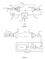
- Figure 1 shows a typical apparatus 100 for calculating the distance between two loudspeakers 110,114.
- An input 102 may be connected to the first loudspeaker 110 via a first delay path 104 having a delay ⁇ T 1 .
- the second loudspeaker 114 may be connected to a first input 118 of a delay calculator 116 via a second delay path 120 having delay ⁇ T 2 .
- the input 102 may be connected to a second input 112 of a delay calculator 116 via a third delay path 106 having a delay ⁇ T 3 .
- a reference signal is played through a first loudspeaker 110 and simultaneously captured by the second loudspeaker 114 which is used as a microphone in this configuration.
- the acoustical delay ⁇ T A (and hence the distance) between both loudspeakers can be calculated from the reference signal and the captured signal.
- the measured delay will also include unknown and potentially time-varying delays ⁇ T 1 , ⁇ T 2 , and ⁇ T 3 which may originate for example from analog to digital and digital to analog conversion delays, operating system delays for an audio system using software, and other circuit delay.
- the combined effect of all these delays can be denoted as the system delay ⁇ T S .
- both loudspeakers are in the same device, the system delay can be compensated for with a reference measurement where the electrical input of 110 is directly connected to the electrical output of 114 shown as the dotted line 108. Even then, it may require dedicated circuitry to make this possible in existing products. In case the loudspeakers 110,114 are not in the same physical device, such electrical shortcut is not possible and other techniques are required so as to account for the system delay. Such techniques may for instance rely on timestamping with as consequence a higher complexity and an increased dependency on external system components.
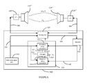
- FIG. 2 shows an acoustic controller 150 according to an embodiment.
- the acoustic controller 150 includes a processor 170 and a detector 180.
- the detector 180 may have an output 156 connected to the processor 170 and a detector input 158.
- the reference signal generator 160 may be coupled to a first acoustic transducer 110' having a voice coil via a first delay path 104' which may include for example a speaker driver.
- the detector input 158 may be coupled to a second acoustic transducer 114' having a voice coil via a second delay path 120'.
- the first and second acoustic transducers 110', 114' may be loudspeakers
- FIG. 3a shows an electrodynamic loudspeaker 110' including a voice coil.
- an AC magnetic field is generated.
- EMF AC electromotive force
- the acoustic coupling transfer function Ha comprises:
- Ha can be estimated using techniques such as for example cross-correlation or adaptive filtering between the reference signal and the detected signal.
- techniques such as for example cross-correlation or adaptive filtering between the reference signal and the detected signal.
- the reference signal generator 160 may be coupled to a first acoustic transducer 110' and the detector input 158 may be coupled to a second acoustic transducer 114'.
- First acoustic transducer 110' and second acoustic transducer 114' each include a voice coil and may be positioned such that they are acoustically and magnetically coupled in operation.
- the processor 170 may receive a detected reference signal from the detector 180 and determine two delay values.
- the processor 170 may determine a first delay value or magnetic coupling delay value ⁇ T M from the signal component due to the magnetic coupling between the first acoustic transducer 110' and the second acoustic transducer 114'.
- the processor 170 may determine a second delay value or acoustic coupling delay value from the signal component due to the acoustic coupling between the first acoustic transducer 110' and the second acoustic transducer 114'.
- the processor 170 may subtract the measured magnetic coupling delay value, corresponding to the system delay, from the measured acoustical coupling delay value to obtain the acoustical delay between the first and second transducers 110', 114' which allows for any system delay ⁇ T S . Consequently a time-of-flight between the first and second acoustic transducers 110', 114' may be determined.
- the determined time-of-flight value may compensate for any system delay and so improve the measurement accuracy of acoustic transducer separation.
- the first and second delay values may be determined by comparison with an internal time reference (not shown).
- the magnetic coupling delay value may be considered as time zero or the start time, since the magnetic coupling component may be detected first.
- the detection of the magnetic coupling component may be used for example to start a counter or other timer (not shown) which may then be stopped when the acoustic signal component is detected.
- the value of the timer when stopped may be a value of the time-of-flight of the acoustic signal ⁇ T A .
- FIG. 4 shows an acoustic controller 200 according to an embodiment.
- the acoustic controller 200 includes a reference signal generator 210, a processor 220 and a detector 230.
- the processor 220 may be connected to an output 202 of the reference signal generator 210.
- the processor 220 may have a control output 204 connected to an input of the reference signal generator 210.
- the detector 220 may have an output 206 connected to the processor 220 and a detector input 208.
- the reference signal generator output 202 may be coupled to a first acoustic transducer 110" having a voice coil via a first delay path 104" which may include for example a speaker driver.
- the detector input 208 may be coupled to a second acoustic transducer 114" having a voice coil via a second delay path 120".
- the first and second acoustic transducers 110", 114" may be loudspeakers.
- the processor 220 may enable the reference signal generator 210 at a first time value.
- the reference signal generator 210 may generate a signal which is transmitted via first acoustic transducer 110".
- a magnetic coupling signal component of the generated signal may be detected via the second transducer 114" at a second time value.
- An acoustic coupling signal component of the generated signal may be detected via the second transducer 114" at a third time value.
- the processor 220 may determine a magnetic coupling delay value from the difference between the second time value and the first time value.
- FIG. 5 shows an acoustic controller 250 according to an embodiment.
- the acoustic controller 250 includes a reference signal generator 260, a processor 270 and a detector 280.
- the processor 270 includes an acoustic delay calculator 262, a magnetic delay calculator 274 and a comparator 266.
- a processor input 256 may be connected to the acoustic delay calculator 262 and the magnetic delay calculator 274.
- the processor input 256 may be connected to an output 252 of the reference signal generator 260 via a delay 254.
- the delay 254 may represent a part of a system delay due to signal conversion, transmission delay, or processing delay.
- the processor 270 may have a control output 258 connected to an input of the reference signal generator 260.
- the acoustic delay calculator 262 may have an output 264 connected to a first input of the comparator 266.
- the magnetic delay calculator may have an output 268 connected to a second input of the comparator 266.
- the comparator 266 may generate a difference between the two input values on a comparator output 272.
- the detector 280 may have an output 276 connected to the acoustic delay calculator 262 and the magnetic delay calculator 274.
- the detector 280 may have a detector input 282.
- the reference signal generator output 252 may be coupled to a first acoustic transducer 110"' having a voice coil via a first delay path 104"'.
- the first delay path 104'" may include for example a speaker driver.
- the detector input 282 may be coupled to a second acoustic transducer 114'" having a voice coil via a second delay path 120"'.
- the first and second acoustic transducers 110"', 114'" may be loudspeakers.
- the first acoustic transducer 110'" may be a loudspeaker and the second acoustic transducer 114'" may be a microphone.
- the first acoustic transducer 110" and/or the second acoustic transducer 114" may be a linear resonant actuator.
- the processor 270 may receive a detected signal from the detector 280 and determine two delay values.
- the magnetic delay calculator 274 may determine a first delay value or magnetic coupling delay value from the signal component due to the magnetic coupling between the first acoustic transducer 110" and the second acoustic transducer 114" for example by correlating the reference signal with the detected signal.
- the acoustic delay calculator 262 may determine a second delay value or acoustic coupling delay value from the signal component due to the acoustic coupling between the first acoustic transducer 110'" and the second acoustic transducer 114'"
- the comparator 266 may determine the difference between the acoustic coupling delay value and the magnetic coupling delay value.
- the resulting difference will therefore compensate the measurement of the acoustic delay for the effect of any system delay ⁇ T S which may be due to a combination of any of the delays 104"', 120"' or other delays not shown.
- the reference signal generator 260 may be implemented by hardware or a combination of hardware and software.
- the processor 270 may be implemented by hardware as digital logic or by software running on a microprocessor or digital signal processor or a combination of both hardware and software.
- the detector 280 may be implemented as hardware.
- the detector 280 may include an analog to digital converter.
- the acoustic delay calculator 262 may store a magnetic delay value in a memory (not shown). The acoustic delay calculator 262 may then provide the stored magnetic delay value as a measure of the system delay if a magnetic coupling delay value cannot be determined from the detected signal. Storing a magnetic coupling delay value which may correspond to the system delay, may allow more accurate time of flight measurements to be made when the acoustic transducers are placed further apart, for example at a distance where there is no detectable magnetic coupling between the transducers.
- FIG. 6 shows an acoustic controller 300 according to an embodiment.
- the acoustic controller 300 includes a reference signal generator 310, a processor 320, a detector 330, and a multiplexer 328.
- the processor 320 includes an acoustic delay calculator 312, a magnetic delay calculator 324 and an averager module 316.
- the processor 320 may have a control output connected to the multiplexer 328.
- the acoustic delay calculator 312 may have an input connected to an output 302 of the reference signal generator 310.
- the magnetic delay calculator 324 may have an input connected to the output 302 of the reference signal generator 310.
- the output 302 of the reference signal generator 310 may be connected to the multiplexer 328.
- the acoustic delay calculator 312 may have an output 314 connected to a first input of the averager module 316.
- the magnetic delay calculator 324 may have an output 318 connected to a second input of the averager module 316.
- the detector 330 may have an input connected to the multiplexer 328.
- the detector 330 may have an output 326 connected to the acoustic delay calculator 312 and the magnetic delay calculator 324.
- the multiplexer 328 may have a first bidirectional connection 304 coupled to a first acoustic transducer 110"" via a first delay path 104"".
- the multiplexer 328 may have a second bidirectional connection 306 coupled to the second acoustic transducer 114"" via a second delay path 120"".
- the first and second acoustic transducers 110"", 114"" may be loudspeakers.
- the first acoustic transducer 110"" may be a loudspeaker and the second acoustic transducer 114"” may be a microphone.
- the first acoustic transducer 110"" and the second acoustic transducer 114"" have a voice coil.
- the first acoustic transducer 110" may be a linear resonant actuator (LRA) and the second acoustic transducer 114"" may be either a microphone or a linear resonant actuator configured as an input sensor.
- LRA linear resonant actuator
- the processor 320 may control the multiplexer 328 in a first mode to couple the reference signal generator output 302 to the first bidirectional connection 304 and the detector input 308 to the second bidirectional connection 306.
- the processor 320 may control the multiplexer 328 in a second mode to couple the reference signal generator output 302 to the second bidirectional connection 306 and the detector input 308 to the first bidirectional connection 304.
- the multiplexer 328 may be implemented in hardware or software. As will be appreciated in other examples, other circuits or software that route the signal generator output and detector input to different bidirectional connections may also be used.
- the acoustic controller 300 may measure the magnetic and acoustic delays in the first mode by transmitting a reference signal via the first acoustic transducer 110"" and detecting the transmitted reference signal via the second acoustic transducer 114"" as previously described for acoustic controller 250.
- the acoustic controller 300 may measure the magnetic and acoustic delays in the second mode by transmitting a reference signal via the second acoustic transducer 114"" and detecting the transmitted reference signal via the first acoustic transducer 110"” similarly as previously described for acoustic controller 250.
- the averager module 316 may determine a difference between the acoustic delay value and the magnetic delay value in each mode.
- the averager module 316 may determine an average compensated acoustic delay value from the measurement taken in each direction and output an average value of the acoustic time of flight on the averager output 322.
- the processor 320 may determine a time of flight value from the average compensated acoustic delay value.
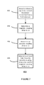
- Figure 7 shows a method for determining a time of flight of an acoustic signal 400.
- the reference signal may be detected via a second transducer having a voice coil which is transmitted from a first transducer having a voice coil.
- the reference signal may have a frequency in the acoustic range which may include infra-sound, audible, or ultrasound signals.
- the first transducer and the second transducer may be positioned such that they are both magnetically and acoustically coupled.
- a magnetic coupling delay value may be determined. The magnetic coupling delay value may be determined from the time difference between transmitting the reference signal and detecting the magnetic coupling component of the detected reference signal.
- the magnetic coupling delay value may be a start time signal and so may have a value of zero.
- an acoustic coupling delay value may be determined.
- the acoustic coupling delay value may be determined from the time difference between transmitting the reference signal and detecting the acoustic coupling component of the detected reference signal. In other examples, the acoustic coupling delay value may be determined directly from the time difference between detecting the magnetic coupling signal component and detecting the acoustic coupling signal component.
- the time of flight of the acoustic signal may be determined from the acoustic coupling delay value and the magnetic coupling delay value.
- the magnetic coupling delay value Since the magnetic coupling delay value has no time delay between the first acoustic transducer and the second acoustic transducer, it may represent the value of the system delay which can then be used to compensate for the measured acoustic coupling delay value. Consequently a more accurate time of flight of the acoustic signal between the first transducer and the second transducer may be determined.
- the method 400 may be implemented in hardware, software running on a microprocessor or a combination of hardware and software.
- An acoustic controller including a detector configured to detect a received reference signal on the terminals of a second acoustic transducer transmitted by a first acoustic transducer, the first and second acoustic transducers having a voice coil; and a processor coupled to the signal generator and the detector, wherein the processor is configured to determine a magnetic-coupling-delay value from the detected reference signal, determine an acoustic-coupling-delay value from the detected reference signal; and determine a time-of-flight value of an acoustic signal transmitted between the first acoustic transducer and the second acoustic transducer from the acoustic-coupling-delay value and the magnetic-coupling-delay value.
- the acoustic controller may be included in mobile devices, for example smartphones, hearable devices for example hearing aids, laptops and tablet computers, personal digital assistants, and wearable devices
Landscapes
- Physics & Mathematics (AREA)
- Acoustics & Sound (AREA)
- Electromagnetism (AREA)
- Thermal Sciences (AREA)
- Fluid Mechanics (AREA)
- General Physics & Mathematics (AREA)
- Stereophonic System (AREA)
Abstract
An acoustic controller is described including a detector configured to detect a received reference signal on the terminals of a second acoustic transducer transmitted by a first acoustic transducer, the first and second acoustic transducers having a voice coil; and a processor coupled to the signal generator and the detector, wherein the processor is configured to determine a magnetic-coupling-delay value from the detected reference signal, determine an acoustic-coupling-delay value from the detected reference signal; and determine a time-of-flight value of an acoustic signal transmitted between the first acoustic transducer and the second acoustic transducer from the acoustic-coupling-delay value and the magnetic-coupling-delay value.
Description
- This disclosure relates to an acoustic controller for determining the time of flight of an acoustic signal.
- Multi-channel audio reproduction such as 5.1 surround sound is currently limited to stationary home installations due to the multiplicity of loudspeakers. Mobile devices, and especially smartphones, have increasing audio reproduction capabilities. It may be desirable to enable simultaneous multi-device sound reproduction to further enhance listening experience in case multiple devices are located near each other. Knowing the distance separating the loudspeakers with a sufficiently high accuracy, typically less than 1cm, is required in order to guarantee an accurate control of the sound field generated by the multiple speakers across multiple devices. Techniques exist for calculating device-to-device distance. RF-based solutions for example are based on power level differences and suffer from a poor localization accuracy having an order of magnitude of 1 metre.
- Various aspects of the disclosure are defined in the accompanying claims. In a first aspect there is defined an acoustic controller comprising a detector configured to detect a received reference signal on the terminals of a second acoustic transducer transmitted by a first acoustic transducer, the first and second acoustic transducers having a voice coil; a processor coupled to the signal generator and the detector, wherein the processor is configured to determine a magnetic-coupling-delay value from the detected reference signal, determine an acoustic-coupling-delay value from the detected reference signal, and determine a time-of-flight value of an acoustic signal transmitted between the first acoustic transducer and the second acoustic transducer from the acoustic-coupling-delay value and the magnetic-coupling-delay value.
- In one or more embodiments, the acoustic controller may comprise a reference signal generator coupled to the processor wherein the processor is further configured to compare the detected signal with the generated reference signal.
- In one or more embodiments of the acoustic controller, the detector may be configured to detect a magnetic coupling signal component of the detected reference signal due to the magnetic coupling between the first acoustic transducer and the second acoustic transducer, and the processor may be configured to determine a magnetic-coupling-delay value from the magnetic coupling signal component.
- In one or more embodiments of the acoustic controller, the detector may be configured to detect an acoustic coupling signal component of the detected reference signal due to the acoustic coupling between the first acoustic transducer and the second acoustic transducer and the processor may be further configured to determine the acoustic-coupling-delay value from the acoustic coupling signal component.
- In one or more embodiments of the acoustic controller, the processor may be further configured to determine the time-of-flight value from the difference between the acoustic coupling delay value and the magnetic coupling delay value.
- In one or more embodiments of the acoustic controller, the signal generator may be further configured to generate a further signal for transmission by the second acoustic transducer, the detector is further configured to detect a further signal on the terminals of the first acoustic transducer transmitted by the second acoustic transducer and the processor may be further configured to determine a further magnetic-coupling-delay value dependent on the detected signal, determine a further acoustic-coupling-delay value dependent on the detected signal; and determine the time-of-flight value of an acoustic signal transmitted between the second acoustic transducer and the first acoustic transducer from the acoustic-coupling-delay value, the further acoustic-coupling-delay value, the magnetic-coupling-delay value and the further magnetic-coupling-delay value.
- In one or more embodiments of the acoustic controller, the processor may be further configured to determine the time-of-flight value from the difference between the average of the acoustic-coupling-delay value and the further acoustic-coupling-delay value and the average of the magnetic-coupling-delay value and the further magnetic-coupling-delay value.
- In one or more embodiments the acoustic controller may further comprise a memory coupled to the processor, wherein the memory is configured to store the determined magnetic coupling delay value and the processor is further configured to determine further time-of-flight values from the acoustic coupling delay value and the stored magnetic coupling delay value.
- An audio system may include the acoustic controller coupled to the first and second acoustic transducers. The acoustic transducers may comprise one of a loudspeaker, an electrodynamic microphone and a linear resonant actuator.
- In a second aspect there is defined a method for determining a distance between two acoustic transducers, each of the acoustic transducers comprising a voice coil, the method comprising detecting a reference signal via a second acoustic transducer transmitted from the first transducer, determining a magnetic coupling delay value dependent on the detected signal and the generated signal, determining an acoustic coupling delay value dependent on the detected signal and the generated signal; and determining a time-of-flight value of an acoustic signal transmitted between the first acoustic transducer and the second acoustic transducer from the acoustic coupling delay value and the magnetic coupling delay value.
- In one or more embodiments, determining a distance between the first acoustic transducer and the second acoustic transducer may further comprise determining the difference between the acoustic coupling delay value and the magnetic coupling delay value.
- In one or more embodiments, determining the magnetic coupling delay value may further comprise detecting a magnetic-coupling-signal component of the signal due to the magnetic coupling between the first acoustic transducer and the second acoustic transducer.
- In one or more embodiments, determining the acoustic coupling delay value may further comprise detecting an acoustic-coupling-signal component of the signal due to the acoustic coupling between the first acoustic transducer and the second acoustic transducer.
- In one or more embodiments, the method may further comprise generating a further signal, transmitting the further signal via the second acoustic transducer, detecting the further transmitted signal via the first acoustic transducer, determining a further magnetic coupling delay value dependent on the further detected signal and the further generated signal, determining a further acoustic coupling delay value dependent on the detected signal and the generated signal; and determining a time-of-flight value of an acoustic signal transmitted between the second acoustic transducer and the first acoustic transducer from the acoustic coupling delay value, the further acoustic coupling delay value, the magnetic coupling delay value, and the further magnetic coupling delay value.
- In one or more embodiments, the method may further comprise arranging the first acoustic transducer and the second acoustic transducer at a first distance such that the first acoustic transducer and the second acoustic transducer are at least magnetically coupled in operation, determining the magnetic coupling delay value, arranging the first acoustic transducer and the second acoustic transducer at a second distance such that the speaker and the second speaker are at least acoustically coupled in operation, determining the acoustic coupling delay value, wherein determining the distance comprises determining the second distance from the acoustic coupling delay value and the magnetic coupling delay value.
- In a third aspect there is described a computer program product comprising instructions which, when being executed by a processing unit, cause said processing unit to perform the steps of detecting a reference signal via a second acoustic transducer, transmitted from a first transducer, determining a magnetic coupling delay value dependent on the detected signal and the generated signal, determining an acoustic coupling delay value dependent on the detected signal and the generated signal; and determining a time-of-flight value of an acoustic signal transmitted between the first acoustic transducer and the second acoustic transducer from the acoustic coupling delay value and the magnetic coupling delay value.
- In the figures and description like reference numerals refer to like features. Embodiments of the invention are now described in detail, by way of example only, illustrated by the accompanying drawings in which:
-
Figure 1 shows a typical arrangement for determining the separation of two loudspeakers. -
Figure 2 illustrates an acoustic controller according to an embodiment. -
Figure 3 Shows a) a loudspeaker showing the ac magnetic field produced b) two mutually coupled loudspeakers c) two loudspeakers acoustically and magnetically coupled. -
Figure 4 illustrates an acoustic controller according to an embodiment connected to two acoustic transducers having voice coils. -
Figure 5 illustrates an acoustic controller according to an embodiment connected to two acoustic transducers having voice coils. -
Figure 6 shows an acoustic controller according to an embodiment connected to two acoustic transducers having voice coils. -
Figure 7 illustrates a method of determining a time of flight between two acoustic transducers according to an embodiment. -
Figure 1 shows atypical apparatus 100 for calculating the distance between two loudspeakers 110,114. Aninput 102 may be connected to thefirst loudspeaker 110 via afirst delay path 104 having a delay ΔT1. Thesecond loudspeaker 114 may be connected to afirst input 118 of adelay calculator 116 via asecond delay path 120 having delay ΔT2. - The
input 102 may be connected to asecond input 112 of adelay calculator 116 via athird delay path 106 having a delay ΔT3. - To determine the distance between the loudspeakers 110,114, a reference signal is played through a
first loudspeaker 110 and simultaneously captured by thesecond loudspeaker 114 which is used as a microphone in this configuration. The acoustical delay ΔTA (and hence the distance) between both loudspeakers can be calculated from the reference signal and the captured signal. However, the measured delay will also include unknown and potentially time-varying delays ΔT1, ΔT2, and ΔT3 which may originate for example from analog to digital and digital to analog conversion delays, operating system delays for an audio system using software, and other circuit delay. The combined effect of all these delays can be denoted as the system delay ΔTS. If both loudspeakers are in the same device, the system delay can be compensated for with a reference measurement where the electrical input of 110 is directly connected to the electrical output of 114 shown as thedotted line 108. Even then, it may require dedicated circuitry to make this possible in existing products. In case the loudspeakers 110,114 are not in the same physical device, such electrical shortcut is not possible and other techniques are required so as to account for the system delay. Such techniques may for instance rely on timestamping with as consequence a higher complexity and an increased dependency on external system components. -
Figure 2 shows anacoustic controller 150 according to an embodiment. Theacoustic controller 150 includes a processor 170 and adetector 180. Thedetector 180 may have anoutput 156 connected to the processor 170 and adetector input 158. - In operation the
reference signal generator 160 may be coupled to a first acoustic transducer 110' having a voice coil via afirst delay path 104' which may include for example a speaker driver. Thedetector input 158 may be coupled to a second acoustic transducer 114' having a voice coil via a second delay path 120'. The first and second acoustic transducers 110', 114' may be loudspeakers - The operation of the
acoustic controller 150 may be explained with reference toFigure 3. Figure 3a shows an electrodynamic loudspeaker 110' including a voice coil. When driving the loudspeaker with an AC signal V1, an AC magnetic field is generated. In case of two nearby loudspeakers 110', 114' shown infigure 3b , the AC magnetic field generated by the first loudspeaker 110' will induce an AC electromotive force (EMF) V2 in the voice coil of the second loudspeaker 114'. In addition to being magnetically coupled, both loudspeakers 110', 114' are also acoustically coupled. As illustrated inFigure 3c , when driving the first loudspeaker with voltage V1, the voltage V2 measured across the second loudspeaker terminals will be the superposition of the magnetic and acoustic coupling. The acoustic coupling transfer function Ha comprises: - the first loudspeaker transfer function, typically a minimum-phase delay-less function
- the second loudspeaker sensitivity function, typically a minimum-phase delay-less function
- the acoustic transfer function between both loudspeakers. In case of an anechoic free field radiation, it consists only of a pure delay (ΔTA) and a frequency dependent attenuation factor (not shown), from which the speaker-to-speaker distance can be derived.
- The skilled person will appreciate that Ha can be estimated using techniques such as for example cross-correlation or adaptive filtering between the reference signal and the detected signal. The larger the measurement bandwidth, the higher the time resolution and the higher the time domain accuracy for time delay estimation.
- Since the magnetic coupling transfer function Hm is proportional to the frequency, Hm should preferably be estimated at higher frequencies, typically above 20 kHz. As opposed to the acoustical transfer function, it has no delay and so the effective time of flight of a signal component due to magnetic coupling between the first loudspeaker 110' and the second loudspeaker 114' denoted as ΔTM = 0.
- Referring back to
figure 2 , in operation thereference signal generator 160 may be coupled to a first acoustic transducer 110' and thedetector input 158 may be coupled to a second acoustic transducer 114'. First acoustic transducer 110' and second acoustic transducer 114' each include a voice coil and may be positioned such that they are acoustically and magnetically coupled in operation. The processor 170 may receive a detected reference signal from thedetector 180 and determine two delay values. The processor 170 may determine a first delay value or magnetic coupling delay value ΔTM from the signal component due to the magnetic coupling between the first acoustic transducer 110' and the second acoustic transducer 114'. The processor 170 may determine a second delay value or acoustic coupling delay value from the signal component due to the acoustic coupling between the first acoustic transducer 110' and the second acoustic transducer 114'. - The measured acoustical delay will be ΔTA + ΔTS while the measured magnetic delay will be ΔTM + ΔTS = ΔTS since ΔTM = 0. The processor 170 may subtract the measured magnetic coupling delay value, corresponding to the system delay, from the measured acoustical coupling delay value to obtain the acoustical delay between the first and second transducers 110', 114' which allows for any system delay ΔTS. Consequently a time-of-flight between the first and second acoustic transducers 110', 114' may be determined. The determined time-of-flight value may compensate for any system delay and so improve the measurement accuracy of acoustic transducer separation. Knowing the distance separating acoustic transducers with a sufficiently high accuracy (typically less than 1cm) may allow an accurate control of the sound field generated by multiple acoustic transducers. The first and second delay values may be determined by comparison with an internal time reference (not shown). Alternatively the magnetic coupling delay value may be considered as time zero or the start time, since the magnetic coupling component may be detected first. In this example, the detection of the magnetic coupling component may be used for example to start a counter or other timer (not shown) which may then be stopped when the acoustic signal component is detected. The value of the timer when stopped may be a value of the time-of-flight of the acoustic signal ΔTA.
-
Figure 4 shows anacoustic controller 200 according to an embodiment. Theacoustic controller 200 includes areference signal generator 210, aprocessor 220 and adetector 230. Theprocessor 220 may be connected to anoutput 202 of thereference signal generator 210. Theprocessor 220 may have acontrol output 204 connected to an input of thereference signal generator 210. Thedetector 220 may have anoutput 206 connected to theprocessor 220 and adetector input 208. - In operation of the
acoustic controller 200, the referencesignal generator output 202 may be coupled to a firstacoustic transducer 110" having a voice coil via afirst delay path 104" which may include for example a speaker driver. Thedetector input 208 may be coupled to a secondacoustic transducer 114" having a voice coil via asecond delay path 120". The first and secondacoustic transducers 110", 114" may be loudspeakers. Theprocessor 220 may enable thereference signal generator 210 at a first time value. Thereference signal generator 210 may generate a signal which is transmitted via firstacoustic transducer 110". A magnetic coupling signal component of the generated signal may be detected via thesecond transducer 114" at a second time value. An acoustic coupling signal component of the generated signal may be detected via thesecond transducer 114" at a third time value. Theprocessor 220 may determine a magnetic coupling delay value from the difference between the second time value and the first time value. Theprocessor 220 may determine an acoustic coupling delay value from the difference between the third time value and the first time value. Since the time of flight of the magnetic coupling ΔTm = 0, the processor may determine a time of flight value from the acoustic signal from the difference between the acoustic coupling delay value and the magnetic coupling delay value. -
Figure 5 shows anacoustic controller 250 according to an embodiment. Theacoustic controller 250 includes areference signal generator 260, aprocessor 270 and a detector 280. - The
processor 270 includes anacoustic delay calculator 262, amagnetic delay calculator 274 and acomparator 266. - A
processor input 256 may be connected to theacoustic delay calculator 262 and themagnetic delay calculator 274. Theprocessor input 256 may be connected to anoutput 252 of thereference signal generator 260 via a delay 254. The delay 254 may represent a part of a system delay due to signal conversion, transmission delay, or processing delay. Theprocessor 270 may have acontrol output 258 connected to an input of thereference signal generator 260. Theacoustic delay calculator 262 may have anoutput 264 connected to a first input of thecomparator 266. The magnetic delay calculator may have anoutput 268 connected to a second input of thecomparator 266. Thecomparator 266 may generate a difference between the two input values on acomparator output 272. The detector 280 may have anoutput 276 connected to theacoustic delay calculator 262 and themagnetic delay calculator 274. The detector 280 may have adetector input 282. - In operation of the
acoustic controller 250, the referencesignal generator output 252 may be coupled to a firstacoustic transducer 110"' having a voice coil via afirst delay path 104"'. Thefirst delay path 104'" may include for example a speaker driver. Thedetector input 282 may be coupled to a second acoustic transducer 114'" having a voice coil via asecond delay path 120"'. The first and secondacoustic transducers 110"', 114'" may be loudspeakers. In other examples the first acoustic transducer 110'" may be a loudspeaker and the second acoustic transducer 114'" may be a microphone. In other examples, the firstacoustic transducer 110" and/or the secondacoustic transducer 114" may be a linear resonant actuator. - The
processor 270 may receive a detected signal from the detector 280 and determine two delay values. Themagnetic delay calculator 274 may determine a first delay value or magnetic coupling delay value from the signal component due to the magnetic coupling between the firstacoustic transducer 110" and the secondacoustic transducer 114" for example by correlating the reference signal with the detected signal. Theacoustic delay calculator 262 may determine a second delay value or acoustic coupling delay value from the signal component due to the acoustic coupling between the first acoustic transducer 110'" and the second acoustic transducer 114'" Thecomparator 266 may determine the difference between the acoustic coupling delay value and the magnetic coupling delay value. The measured acoustical delay will be ΔTA + ΔTS while the measured magnetic delay will be ΔTM + ΔTS = ΔTS since ΔTM = 0. The resulting difference will therefore compensate the measurement of the acoustic delay for the effect of any system delay ΔTS which may be due to a combination of any of thedelays 104"', 120"' or other delays not shown. - The
reference signal generator 260 may be implemented by hardware or a combination of hardware and software. For example, theprocessor 270 may be implemented by hardware as digital logic or by software running on a microprocessor or digital signal processor or a combination of both hardware and software. The detector 280 may be implemented as hardware. The detector 280 may include an analog to digital converter. - In other embodiments, the
acoustic delay calculator 262 may store a magnetic delay value in a memory (not shown). Theacoustic delay calculator 262 may then provide the stored magnetic delay value as a measure of the system delay if a magnetic coupling delay value cannot be determined from the detected signal. Storing a magnetic coupling delay value which may correspond to the system delay, may allow more accurate time of flight measurements to be made when the acoustic transducers are placed further apart, for example at a distance where there is no detectable magnetic coupling between the transducers. -
Figure 6 shows anacoustic controller 300 according to an embodiment. Theacoustic controller 300 includes areference signal generator 310, aprocessor 320, adetector 330, and amultiplexer 328. Theprocessor 320 includes anacoustic delay calculator 312, amagnetic delay calculator 324 and anaverager module 316. Theprocessor 320 may have a control output connected to themultiplexer 328. - The
acoustic delay calculator 312 may have an input connected to anoutput 302 of thereference signal generator 310. Themagnetic delay calculator 324 may have an input connected to theoutput 302 of thereference signal generator 310. Theoutput 302 of thereference signal generator 310 may be connected to themultiplexer 328. - The
acoustic delay calculator 312 may have anoutput 314 connected to a first input of theaverager module 316. Themagnetic delay calculator 324 may have anoutput 318 connected to a second input of theaverager module 316. Thedetector 330 may have an input connected to themultiplexer 328. Thedetector 330 may have anoutput 326 connected to theacoustic delay calculator 312 and themagnetic delay calculator 324. - In operation of the
acoustic controller 300, themultiplexer 328 may have a firstbidirectional connection 304 coupled to a firstacoustic transducer 110"" via afirst delay path 104"". Themultiplexer 328 may have a secondbidirectional connection 306 coupled to the secondacoustic transducer 114"" via asecond delay path 120"". The first and secondacoustic transducers 110"", 114"" may be loudspeakers. In other examples the firstacoustic transducer 110"" may be a loudspeaker and the secondacoustic transducer 114"" may be a microphone. The firstacoustic transducer 110"" and the secondacoustic transducer 114"" have a voice coil. In other examples, the firstacoustic transducer 110" may be a linear resonant actuator (LRA) and the secondacoustic transducer 114"" may be either a microphone or a linear resonant actuator configured as an input sensor. - In operation the
processor 320 may control themultiplexer 328 in a first mode to couple the referencesignal generator output 302 to the firstbidirectional connection 304 and thedetector input 308 to the secondbidirectional connection 306. Theprocessor 320 may control themultiplexer 328 in a second mode to couple the referencesignal generator output 302 to the secondbidirectional connection 306 and thedetector input 308 to the firstbidirectional connection 304. Themultiplexer 328 may be implemented in hardware or software. As will be appreciated in other examples, other circuits or software that route the signal generator output and detector input to different bidirectional connections may also be used. - The
acoustic controller 300 may measure the magnetic and acoustic delays in the first mode by transmitting a reference signal via the firstacoustic transducer 110"" and detecting the transmitted reference signal via the secondacoustic transducer 114"" as previously described foracoustic controller 250. Theacoustic controller 300 may measure the magnetic and acoustic delays in the second mode by transmitting a reference signal via the secondacoustic transducer 114"" and detecting the transmitted reference signal via the firstacoustic transducer 110"" similarly as previously described foracoustic controller 250. Theaverager module 316 may determine a difference between the acoustic delay value and the magnetic delay value in each mode. Theaverager module 316 may determine an average compensated acoustic delay value from the measurement taken in each direction and output an average value of the acoustic time of flight on theaverager output 322. Theprocessor 320 may determine a time of flight value from the average compensated acoustic delay value. By measuring the acoustic delay between the first and second acoustic transducer in both directions the accuracy of the measurement may be further improved. As will be appreciated, the acoustic controller 350 may make multiple measurements in one or both directions to further improve the accuracy. -
Figure 7 shows a method for determining a time of flight of anacoustic signal 400. Instep 402 the reference signal may be detected via a second transducer having a voice coil which is transmitted from a first transducer having a voice coil. The reference signal may have a frequency in the acoustic range which may include infra-sound, audible, or ultrasound signals. The first transducer and the second transducer may be positioned such that they are both magnetically and acoustically coupled. In step 404 a magnetic coupling delay value may be determined. The magnetic coupling delay value may be determined from the time difference between transmitting the reference signal and detecting the magnetic coupling component of the detected reference signal. Alternatively the magnetic coupling delay value may be a start time signal and so may have a value of zero. Instep 406 an acoustic coupling delay value may be determined. The acoustic coupling delay value may be determined from the time difference between transmitting the reference signal and detecting the acoustic coupling component of the detected reference signal. In other examples, the acoustic coupling delay value may be determined directly from the time difference between detecting the magnetic coupling signal component and detecting the acoustic coupling signal component. Instep 408 the time of flight of the acoustic signal may be determined from the acoustic coupling delay value and the magnetic coupling delay value. Since the magnetic coupling delay value has no time delay between the first acoustic transducer and the second acoustic transducer, it may represent the value of the system delay which can then be used to compensate for the measured acoustic coupling delay value. Consequently a more accurate time of flight of the acoustic signal between the first transducer and the second transducer may be determined. Themethod 400 may be implemented in hardware, software running on a microprocessor or a combination of hardware and software. - An acoustic controller is described including a detector configured to detect a received reference signal on the terminals of a second acoustic transducer transmitted by a first acoustic transducer, the first and second acoustic transducers having a voice coil; and a processor coupled to the signal generator and the detector, wherein the processor is configured to determine a magnetic-coupling-delay value from the detected reference signal, determine an acoustic-coupling-delay value from the detected reference signal; and determine a time-of-flight value of an acoustic signal transmitted between the first acoustic transducer and the second acoustic transducer from the acoustic-coupling-delay value and the magnetic-coupling-delay value.
- The acoustic controller may be included in mobile devices, for example smartphones, hearable devices for example hearing aids, laptops and tablet computers, personal digital assistants, and wearable devices
- Although the appended claims are directed to particular combinations of features, it should be understood that the scope of the disclosure of the present invention also includes any novel feature or any novel combination of features disclosed herein either explicitly or implicitly or any generalisation thereof, whether or not it relates to the same invention as presently claimed in any claim and whether or not it mitigates any or all of the same technical problems as does the present invention.
- Features which are described in the context of separate embodiments may also be provided in combination in a single embodiment. Conversely, various features which are, for brevity, described in the context of a single embodiment, may also be provided separately or in any suitable sub combination.
- The applicant hereby gives notice that new claims may be formulated to such features and/or combinations of such features during the prosecution of the present application or of any further application derived therefrom.
- For the sake of completeness it is also stated that the term "comprising" does not exclude other elements or steps, the term "a" or "an" does not exclude a plurality, a single processor or other unit may fulfil the functions of several means recited in the claims and reference signs in the claims shall not be construed as limiting the scope of the claims.
Claims (15)
- An acoustic controller comprising:a detector configured to detect a received reference signal on the terminals of a second acoustic transducer transmitted by a first acoustic transducer, the first and second acoustic transducers having a voice coil;a processor coupled to the signal generator and the detector; wherein the processor is configured todetermine a magnetic-coupling-delay value from the detected reference signal,determine an acoustic-coupling-delay value from the detected reference signal, anddetermine a time-of-flight value of an acoustic signal transmitted between the first acoustic transducer and the second acoustic transducer from the acoustic-coupling-delay value and the magnetic-coupling-delay value.
- The acoustic controller of claim 1 further comprising a reference signal generator coupled to the processor and wherein the processor is further configured to compare the detected signal with the generated reference signal.
- The acoustic controller of any preceding claim wherein the detector is configured to detect a magnetic coupling signal component of the detected reference signal due to the magnetic coupling between the first acoustic transducer and the second acoustic transducer, and the processor is configured to determine a magnetic-coupling-delay value from the magnetic coupling signal component.
- The acoustic controller of any preceding claim wherein the detector is configured to detect an acoustic coupling signal component of the detected reference signal due to the acoustic coupling between the first acoustic transducer and the second acoustic transducer and the processor is further configured to determine the acoustic-coupling-delay value from the acoustic coupling signal component.
- The acoustic controller of any preceding claim wherein the processor is further configured to determine the time-of-flight value from the difference between the acoustic coupling delay value and the magnetic coupling delay value.
- The acoustic controller of any of claims 2 to 4 wherein the signal generator is further configured to generate a further signal for transmission by the second acoustic transducer, the detector is further configured to detect a further signal on the terminals of the first acoustic transducer transmitted by the second acoustic transducer and wherein the processor is further configured to:determine a further magnetic-coupling-delay value dependent on the detected signal;determine a further acoustic-coupling-delay value dependent on the detected signal; anddetermine the time-of-flight value of an acoustic signal transmitted between the second acoustic transducer and the first acoustic transducer from the acoustic-coupling-delay value, the further acoustic-coupling-delay value, the magnetic-coupling-delay value and the further magnetic-coupling-delay value.
- The acoustic controller of claim 6 wherein the processor is configured to determine the time-of-flight value from the difference between the average of the acoustic-coupling-delay value and the further acoustic-coupling-delay value and the average of the magnetic-coupling-delay value and the further magnetic-coupling-delay value.
- The acoustic controller of any preceding claim further comprising a memory coupled to the processor, wherein the memory is configured to store the determined magnetic coupling delay value and the processor is further configured to determine further time-of-flight values from the acoustic coupling delay value and the stored magnetic coupling delay value.
- An audio system comprising the acoustic controller of any preceding claim coupled to the first and second acoustic transducers wherein the first and second acoustic transducers comprise one of a loudspeaker and electrodynamic microphone and a linear resonant actuator.
- A method for determining a distance between two acoustic transducers, each of the acoustic transducers comprising a voice coil, the method comprising:detecting a reference signal via a second acoustic transducer, transmitted from the first transducer,determining a magnetic coupling delay value dependent on the detected signal and the generated signal,determining an acoustic coupling delay value dependent on the detected signal and the generated signal; anddetermining a time-of-flight value of an acoustic signal transmitted between the first acoustic transducer and the second acoustic transducer from the acoustic coupling delay value and the magnetic coupling delay value.
- The method of claim 10 wherein determining a distance between the first acoustic transducer and the second acoustic transducer further comprises determining the difference between the acoustic coupling delay value and the magnetic coupling delay value.
- The method of any of claims 10 to 11 wherein determining the magnetic coupling delay value further comprises detecting a magnetic-coupling-signal component of the signal due to the magnetic coupling between the first acoustic transducer and the second acoustic transducer.
- The method of any of claims 10 to 12 wherein determining the acoustic coupling delay value further comprises detecting an acoustic-coupling-signal component of the signal due to the acoustic coupling between the first acoustic transducer and the second acoustic transducer.
- The method of any of claims 10 to 13 further comprising
generating a further signal,
transmitting the further signal via the second acoustic transducer,
detecting the further transmitted signal via the first acoustic transducer,
determining a further magnetic coupling delay value dependent on the further detected signal and the further generated signal,
determining a further acoustic coupling delay value dependent on the detected signal and the generated signal; and
determining a time-of-flight value of an acoustic signal transmitted between the second acoustic transducer and the first acoustic transducer from the acoustic coupling delay value, the further acoustic coupling delay value, the magnetic coupling delay value, and the further magnetic coupling delay value. - The method of any of claims 10 to 14 further comprising:arranging the first acoustic transducer and the second acoustic transducer at a first distance such that the first acoustic transducer and the second acoustic transducer are at least magnetically coupled in operation,determining the magnetic coupling delay value,arranging the first acoustic transducer and the second acoustic transducer at a second distance such that the speaker and the second speaker are at least acoustically coupled in operation,determining the acoustic coupling delay value,wherein determining the distance comprises determining the second distance from the acoustic coupling delay value and the magnetic coupling delay value.
Priority Applications (1)
| Application Number | Priority Date | Filing Date | Title |
|---|---|---|---|
| EP16173865.3A EP3255425A1 (en) | 2016-06-10 | 2016-06-10 | Acoustic controller |
Applications Claiming Priority (1)
| Application Number | Priority Date | Filing Date | Title |
|---|---|---|---|
| EP16173865.3A EP3255425A1 (en) | 2016-06-10 | 2016-06-10 | Acoustic controller |
Publications (1)
| Publication Number | Publication Date |
|---|---|
| EP3255425A1 true EP3255425A1 (en) | 2017-12-13 |
Family
ID=56119372
Family Applications (1)
| Application Number | Title | Priority Date | Filing Date |
|---|---|---|---|
| EP16173865.3A Withdrawn EP3255425A1 (en) | 2016-06-10 | 2016-06-10 | Acoustic controller |
Country Status (1)
| Country | Link |
|---|---|
| EP (1) | EP3255425A1 (en) |
Citations (2)
| Publication number | Priority date | Publication date | Assignee | Title |
|---|---|---|---|---|
| WO1997049010A1 (en) * | 1996-06-20 | 1997-12-24 | Peek Measurement, Inc. | Method and system for high resolution time-of-flight measurements |
| US20110288795A1 (en) * | 2010-05-18 | 2011-11-24 | Avago Technologies Wireless Ip (Singapore) Pte. Ltd. | Method and system for determining the time-of-flight of an acoustic signal |
-
2016
- 2016-06-10 EP EP16173865.3A patent/EP3255425A1/en not_active Withdrawn
Patent Citations (2)
| Publication number | Priority date | Publication date | Assignee | Title |
|---|---|---|---|---|
| WO1997049010A1 (en) * | 1996-06-20 | 1997-12-24 | Peek Measurement, Inc. | Method and system for high resolution time-of-flight measurements |
| US20110288795A1 (en) * | 2010-05-18 | 2011-11-24 | Avago Technologies Wireless Ip (Singapore) Pte. Ltd. | Method and system for determining the time-of-flight of an acoustic signal |
Similar Documents
| Publication | Publication Date | Title |
|---|---|---|
| US10839808B2 (en) | Detection of replay attack | |
| US9872116B2 (en) | Apparatus and method for detecting earphone removal and insertion | |
| WO2014173069A1 (en) | Sound effect adjusting method, apparatus, and device | |
| WO2004054319A1 (en) | Method and device for measuring sound wave propagation time between loudspeaker and microphone | |
| JP2013148576A (en) | Portable device performing position specification using modulated background sound, computer program, and method | |
| US20150036859A1 (en) | Expandable electronic device and transmission system thereof | |
| CN111526467A (en) | Acoustic listening area mapping and frequency correction | |
| US11480547B2 (en) | Liquid immersion sensor | |
| US20170038468A1 (en) | Terminal and Method for Ranging Using Terminal | |
| CN104198894A (en) | Cable digital display synchronous fixed point path instrument and fixed point method thereof | |
| JP6361680B2 (en) | Sound field control system, analysis device, acoustic device, control method for sound field control system, control method for analysis device, control method for acoustic device, program, recording medium | |
| TWI601131B (en) | Noise removing device, echo canceling device, abnormal sound detecting device, and noise removing method | |
| CN110869793A (en) | Determine the position/orientation of the audio device | |
| CN112130135A (en) | Interference mitigation using sensor fusion within a device | |
| JP2003274491A (en) | Speaker disconnection detection device | |
| JP4960838B2 (en) | Distance measuring device, distance measuring method, distance measuring program, and recording medium | |
| CN104717595A (en) | Detection method and device for loudspeaker module functions | |
| CN115580809A (en) | Sound positioning compensation method and device | |
| US9357322B2 (en) | Loudspeaker polarity detector | |
| CN217064005U (en) | Hearing device | |
| KR102532584B1 (en) | Detection of replay attacks | |
| EP3255425A1 (en) | Acoustic controller | |
| KR102030451B1 (en) | Ultrasonic sensor and control method thereof | |
| JP2012191541A (en) | Delay measurement device, delay measurement method and computer program | |
| EP3182734B1 (en) | Method for using a mobile device equipped with at least two microphones for determining the direction of loudspeakers in a setup of a surround sound system |
Legal Events
| Date | Code | Title | Description |
|---|---|---|---|
| PUAI | Public reference made under article 153(3) epc to a published international application that has entered the european phase |
Free format text: ORIGINAL CODE: 0009012 |
|
| STAA | Information on the status of an ep patent application or granted ep patent |
Free format text: STATUS: THE APPLICATION HAS BEEN PUBLISHED |
|
| AK | Designated contracting states |
Kind code of ref document: A1 Designated state(s): AL AT BE BG CH CY CZ DE DK EE ES FI FR GB GR HR HU IE IS IT LI LT LU LV MC MK MT NL NO PL PT RO RS SE SI SK SM TR |
|
| AX | Request for extension of the european patent |
Extension state: BA ME |
|
| STAA | Information on the status of an ep patent application or granted ep patent |
Free format text: STATUS: THE APPLICATION IS DEEMED TO BE WITHDRAWN |
|
| 18D | Application deemed to be withdrawn |
Effective date: 20180614 |