EP3255409A1 - Method of detecting galvanic insulation integrity - Google Patents
Method of detecting galvanic insulation integrity Download PDFInfo
- Publication number
- EP3255409A1 EP3255409A1 EP17174424.6A EP17174424A EP3255409A1 EP 3255409 A1 EP3255409 A1 EP 3255409A1 EP 17174424 A EP17174424 A EP 17174424A EP 3255409 A1 EP3255409 A1 EP 3255409A1
- Authority
- EP
- European Patent Office
- Prior art keywords
- electrical resistance
- resistance
- electrical
- components
- measured
- Prior art date
- Legal status (The legal status is an assumption and is not a legal conclusion. Google has not performed a legal analysis and makes no representation as to the accuracy of the status listed.)
- Granted
Links
Images




Classifications
-
- G—PHYSICS
- G01—MEASURING; TESTING
- G01N—INVESTIGATING OR ANALYSING MATERIALS BY DETERMINING THEIR CHEMICAL OR PHYSICAL PROPERTIES
- G01N27/00—Investigating or analysing materials by the use of electric, electrochemical, or magnetic means
- G01N27/02—Investigating or analysing materials by the use of electric, electrochemical, or magnetic means by investigating impedance
- G01N27/04—Investigating or analysing materials by the use of electric, electrochemical, or magnetic means by investigating impedance by investigating resistance
- G01N27/14—Investigating or analysing materials by the use of electric, electrochemical, or magnetic means by investigating impedance by investigating resistance of an electrically-heated body in dependence upon change of temperature
-
- G—PHYSICS
- G01—MEASURING; TESTING
- G01N—INVESTIGATING OR ANALYSING MATERIALS BY DETERMINING THEIR CHEMICAL OR PHYSICAL PROPERTIES
- G01N17/00—Investigating resistance of materials to the weather, to corrosion, or to light
- G01N17/02—Electrochemical measuring systems for weathering, corrosion or corrosion-protection measurement
Definitions
- a dielectric insulation layer is located between a first dissimilar metal and a second dissimilar metal at the joint to prevent potentially damaging galvanic corrosion at the dissimilar metal joint. Damage to or loss of integrity of the dielectric insulation can result in an electrical connection between the two metals, leading to galvanic corrosion.
- a method of assessing galvanic electronic isolation of two components at a joint of the two components includes measuring a first electrical resistance at a first condition across a joint of two components and comparing the first electrical resistance to a threshold resistance. The comparison of the first electrical resistance to the threshold resistance is indicative of a degree of electrical isolation of the two components. A second electrical resistance is measured at a second condition and the second electrical resistance is compared to the first electrical resistance. The result of the comparison of the second electrical resistance to the first electrical resistance is indicative of a type of electrical connection between the two components.
- the first electrical resistance is measured at a first temperature
- the second electrical resistance is measured at a second temperature
- the joint is heated to the second temperature.
- the joint is heated via one of an oven, or a heat gun, or some other heating device such as a laser beam.
- the first electrical resistance is measured at a first lower frequency
- the second electrical resistance is measured at a second higher frequency
- a difference between the first electrical resistance and the second electrical resistance is indicative of an ionic conduction condition across the joint.
- a second electrical resistance equal to the first electrical resistance is indicative of a galvanic electronic connection between the two components.
- a system for assessing electrical isolation of two components at a joint of the two components includes a resistance measuring device electrically connected to the two components, and an evaluation device connected to the resistance measuring device and configured to compare a first electrical resistance measured at a first condition to a threshold resistance. The comparison of the first electrical resistance to the threshold resistance is indicative of a degree of electrical isolation of the two components.
- the evaluation device is configured to compare a second electrical resistance measured at a second condition to the first electrical resistance. The result of the comparison of the second electrical resistance to the first electrical resistance is indicative of a type of electrical connection between the two components.
- an oven and/or a heat gun or some other heating method is utilized to heat the joint to the second temperature.
- the first electrical resistance is measured at a first polarity
- the second electrical resistance is measured at a second polarity
- the first electrical resistance is measured at a first electrical voltage V1
- the second electrical resistance is measured at a second electrical voltage V2 that is different from the first electrical voltage
- the first electrical resistance/impedance is measured at a first lower frequency
- the second electrical resistance/impedance is measured at a second higher frequency
- a difference between the first electrical resistance and the second electrical resistance is indicative of an ionic conduction condition across the joint, and a second electrical resistance equal to the first electrical resistance is indicative of a galvanic electronic connection between the two components.
- FIG. 1 is a schematic illustration of a gas turbine engine 10.
- the gas turbine engine generally has includes fan section 12, a low pressure compressor 14, a high pressure compressor 16, a combustor 18, a high pressure turbine 20 and a low pressure turbine 22.
- the gas turbine engine 10 is circumferentially disposed about an engine centreline X.
- air is pulled into the gas turbine engine 10 by the fan section 12, pressurized by the compressors 14, 16, mixed with fuel and burned in the combustor 18.
- Hot combustion gases generated within the combustor 18 flow through high and low pressure turbines 20, 22, which extract energy from the hot combustion gases.
- the high pressure turbine 20 utilizes the extracted energy from the hot combustion gases to power the high pressure compressor 16 through a high speed shaft 24, and the low pressure turbine 22 utilizes the energy extracted from the hot combustion gases to power the low pressure compressor 14 and the fan section 12 through a low speed shaft 26.
- the present disclosure is not limited to the two-spool configuration described and may be utilized with other configurations, such as single-spool or three-spool configurations, or gear-driven fan configurations.
- Gas turbine engine 10 is in the form of a high bypass ratio turbine engine mounted within a nacelle or fan casing 28 which surrounds an engine casing 30 housing an engine core 32.
- a significant amount of air pressurized by the fan section 12 bypasses the engine core 32 for the generation of propulsive thrust.
- the airflow entering the fan section 12 may bypass the engine core 32 via a fan bypass passage 34 extending between the fan casing 28 and the engine casing 30 for receiving and communicating a discharge flow F1.
- the high bypass flow arrangement provides a significant amount of thrust for powering an aircraft.
- the engine casing 30 generally includes an inlet case 36, a low pressure compressor case 38, and an intermediate case 40.
- the inlet case 36 guides air to the low pressure compressor case 38, and via a splitter 42 also directs air through the fan bypass passage 34.
- the fan section 12 includes a plurality of fan blades 44 extending radially outwardly from a hub 46.
- the fan blade 44 includes an airfoil body 48 formed from a first metal, for example, an aluminium alloy.
- a leading edge portion 50 is joined to the airfoil body 48 and is formed from a second metal, for example, a titanium alloy to improve erosion and impact resistance of the fan blade 44. While the description herein is in the context of a fan blade 44, one skilled in the art will readily appreciate that the apparatus and method described herein may be utilized with a wide array of joints between components formed from dissimilar metals.
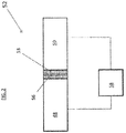
- FIG. 2 Shown in FIG. 2 is a cross-sectional view of such a joint.
- a first component for example, airfoil body 48 formed from a first metal is joined to a second component, for example, leading edge portion 50, formed from a second metal, dissimilar to the first metal.
- the airfoil body 48 is joined to the leading edge portion 50 by an adhesive layer 54 located between the airfoil body 48 and the leading edge portion 50.
- the adhesive layer 54 also acts as a dielectric insulator between the airfoil body 48and the leading edge portion 50, while in other embodiments such as shown in FIG. 2 a separate dielectric insulation layer 56 is located between the airfoil body 48 and the leading edge portion 50.
- the check would need to distinguish between a true electrical connection and an ionic conduction condition due to the presence of, for example, an electrolytic film at the joint 52.
- the check occurs as part of the manufacturing process while in other embodiments, the check may be performed periodically during the service life of the airfoil body 48 and the leading edge portion 50 to ensure continued integrity of the dielectric insulation layer 56.
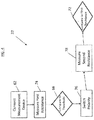
- the method 60 includes connecting the multimeter 58 to the airfoil body 48 and the leading edge portion 50 at block 62, and measuring a first resistance across the joint 52 at block 64.
- the first resistance is measured while the joint 52 is at room temperature, or in ambient conditions.
- the first resistance is compared to a threshold resistance at block 66, at an evaluation device.
- the threshold resistance is about one gigaohm or 1x10 9 ohms (1G ⁇ ).
- a measurement of the first resistance equal to or greater than the threshold is indicative of the airfoil body 48 and the leading edge portion 50 having a selected degree of electrical isolation from each other.
- the airfoil body 48 and the leading edge portion 50 have a degree of electrical connection therebetween, and further method steps will determine whether the electrical connection is one of ionic conduction, which will not result in galvanic corrosion, or a true electrical connection which will result in galvanic corrosion.
- the electrical resistance of metals has a positive temperature coefficient, i.e., the electrical resistance increases with an increase in temperature.
- aluminium has a positive electrical resistance temperature coefficient of about 4.3x10 -3 . With a temperature increase of 10° Celsius, the electrical resistance will increase by about 4.3%.
- resistance due to ionic conduction has a negative temperature coefficient. In ionic conduction, as the temperature increases the ions will move faster and the electrical resistance will decrease. The negative temperature coefficient depends on the specific ionic system, but it is more significant than for metals, on the order of about -20x10 -3 . Restated, for a temperature increase of 10° Celsius, the ionic resistance will decrease by about 20%. Thus, the result of the comparison between the first measured resistance and the second measured resistance will indicate whether ionic conduction or a true electronic connection is present.
- the first resistance is measured at a first polarity 74, and the leads connected to the airfoil body 48 and the leading edge portion 50 are switched at block 76, reversing the polarity.
- the second resistance is measured at block 78 at the reversed polarity.
- the first resistance is compared to the second resistance at block 80, with no difference between the first resistance and the second resistance indicative of a true electronic connection leading to galvanic corrosion, while if the first resistance is different from the second resistance, the result of the comparison is indicative of ionic conduction and not a true electronic connection.
- the first resistance is measured at a first lower potential (V1) 82 while the second resistance is measured at a higher potential (V2) 84.
- V1 first lower potential
- V2 higher potential
- the potential at which the first resistance and the second resistance is measured may be varied, with a difference in the measured resistances indicative of ionic conduction, while when the measured resistance is constant the result is indicative of a true electronic connection leading to galvanic corrosion.
- the first resistance is measured at a lower frequency (for example, 0 Hz direct current) 86 while the second resistance is measured at a higher frequency (for example, at 1 KHz) 88.
- the frequency at which the first resistance and the second resistance is measured may be varied, with a difference in the measured resistances indicative of ionic conduction, while when the measured resistance is constant the result is indicative of a true electronic connection leading to galvanic corrosion.
Landscapes
- Life Sciences & Earth Sciences (AREA)
- Chemical & Material Sciences (AREA)
- General Health & Medical Sciences (AREA)
- General Physics & Mathematics (AREA)
- Health & Medical Sciences (AREA)
- Pathology (AREA)
- Analytical Chemistry (AREA)
- Biochemistry (AREA)
- Immunology (AREA)
- Physics & Mathematics (AREA)
- Biodiversity & Conservation Biology (AREA)
- Ecology (AREA)
- Environmental & Geological Engineering (AREA)
- Environmental Sciences (AREA)
- Chemical Kinetics & Catalysis (AREA)
- Electrochemistry (AREA)
- Investigating Or Analyzing Materials By The Use Of Electric Means (AREA)
Abstract
Description
- This disclosure relates to metallic components, and more particularly to the detection of the integrity of a dielectric insulation layer located between dissimilar metals of a metallic component.
- Many industrial components are formed from metals, and often results in joints where dissimilar metals are joined. Normally, a dielectric insulation layer is located between a first dissimilar metal and a second dissimilar metal at the joint to prevent potentially damaging galvanic corrosion at the dissimilar metal joint. Damage to or loss of integrity of the dielectric insulation can result in an electrical connection between the two metals, leading to galvanic corrosion.
- In addition to detecting a true electrical connection between the two dissimilar metals that would lead to galvanic corrosion, it is desired to distinguish between the true electrical connection and an ionic conduction condition that will not result in galvanic corrosion.
- In one embodiment, a method of assessing galvanic electronic isolation of two components at a joint of the two components includes measuring a first electrical resistance at a first condition across a joint of two components and comparing the first electrical resistance to a threshold resistance. The comparison of the first electrical resistance to the threshold resistance is indicative of a degree of electrical isolation of the two components. A second electrical resistance is measured at a second condition and the second electrical resistance is compared to the first electrical resistance. The result of the comparison of the second electrical resistance to the first electrical resistance is indicative of a type of electrical connection between the two components.
- Additionally or alternatively, in this or other embodiments the first electrical resistance is measured at a first temperature, and the second electrical resistance is measured at a second temperature.
- Additionally or alternatively, in this or other embodiments the second temperature is greater than the first temperature.
- Additionally or alternatively, in this or other embodiments the second temperature is at least 10 degrees Celsius greater than the first temperature.
- Additionally or alternatively, in this or other embodiments the joint is heated to the second temperature.
- Additionally or alternatively, in this or other embodiments the joint is heated via one of an oven, or a heat gun, or some other heating device such as a laser beam.
- Additionally or alternatively, in this or other embodiments if the second electrical resistance is greater than the first electrical resistance, the comparison of the second electrical resistance to the first electrical resistance is indicative of a galvanic electronic connection between the two components.
- Additionally or alternatively, in this or other embodiments if the first electrical resistance is greater than the second electrical resistance, the comparison of the second electrical resistance to the first electrical resistance is indicative of an ionic conduction condition across the joint.
- Additionally or alternatively, in this or other embodiments the first electrical resistance is measured at a first polarity, and the second electrical resistance is measured at a second polarity.
- Additionally or alternatively, in this or other embodiments the first electrical resistance is measured at a first electrical voltage V1, and the second electrical resistance is measured at a second electrical voltage V2.
- Additionally or alternatively, in this or other embodiments the first electrical resistance is measured at a first lower frequency, and the second electrical resistance is measured at a second higher frequency.
- Additionally or alternatively, in this or other embodiments a difference between the first electrical resistance and the second electrical resistance is indicative of an ionic conduction condition across the joint.
- Additionally or alternatively, in this or other embodiments a second electrical resistance equal to the first electrical resistance is indicative of a galvanic electronic connection between the two components.
- Additionally or alternatively, in this or other embodiments a first electrical resistance equal to or greater than the threshold resistance is indicative of a desired electrical isolation of the two components.
- Additionally or alternatively, in this or other embodiments a first component of two components is formed from a first metal and a second component of the two components is formed from a second metal different than the first metal.
- In another embodiment, a system for assessing electrical isolation of two components at a joint of the two components includes a resistance measuring device electrically connected to the two components, and an evaluation device connected to the resistance measuring device and configured to compare a first electrical resistance measured at a first condition to a threshold resistance. The comparison of the first electrical resistance to the threshold resistance is indicative of a degree of electrical isolation of the two components. The evaluation device is configured to compare a second electrical resistance measured at a second condition to the first electrical resistance. The result of the comparison of the second electrical resistance to the first electrical resistance is indicative of a type of electrical connection between the two components.
- Additionally or alternatively, in this or other embodiments the first electrical resistance is measured at a first temperature and the second electrical resistance is measured at a second temperature greater than the first temperature.
- Additionally or alternatively, in this or other embodiments an oven and/or a heat gun or some other heating method is utilized to heat the joint to the second temperature.
- Additionally or alternatively, in this or other embodiments if the second electrical resistance is greater than the first electrical resistance, the comparison of the second electrical resistance to the first electrical resistance is indicative of a galvanic electronic connection between the two components.
- Additionally or alternatively, in this or other embodiments if the first electrical resistance is greater than the second electrical resistance, the comparison of the second electrical resistance to the first electrical resistance is indicative of an ionic conduction condition across the joint.
- Additionally or alternatively, in this or other embodiments the first electrical resistance is measured at a first polarity, and the second electrical resistance is measured at a second polarity.
- Additionally or alternatively, in this or other embodiments the first electrical resistance is measured at a first electrical voltage V1, and the second electrical resistance is measured at a second electrical voltage V2 that is different from the first electrical voltage.
- Additionally or alternatively, in this or other embodiments the first electrical resistance/impedance is measured at a first lower frequency, and the second electrical resistance/impedance is measured at a second higher frequency.
- Additionally or alternatively, in this or other embodiments a difference between the first electrical resistance and the second electrical resistance is indicative of an ionic conduction condition across the joint, and a second electrical resistance equal to the first electrical resistance is indicative of a galvanic electronic connection between the two components.
- The subject matter which is regarded as the present disclosure is particularly pointed out and distinctly claimed in the claims at the conclusion of the specification. The foregoing and other features and advantages of the present disclosure are apparent from the following detailed description taken in conjunction with the accompanying drawings in which:
-
FIG. 1 illustrates a cross-sectional view of an embodiment of a gas turbine engine; -
FIG. 2 illustrates a schematic cross-sectional view of an embodiment of a joint between two dissimilar metal components; -
FIG. 3 is a schematic illustration of a method for assessing galvanic isolation of a joint between a first component and a second component; -
FIG. 4 is a schematic illustration of another method for assessing galvanic isolation of a joint between a first component and a second component; -
FIG. 5 is a schematic illustration of a third method for assessing galvanic isolation of a joint between a first component and a second component; and -
FIG. 6 is a schematic illustration of a fourth method for assessing galvanic isolation of a joint between a first component and a second component. -
FIG. 1 is a schematic illustration of agas turbine engine 10. The gas turbine engine generally has includesfan section 12, alow pressure compressor 14, ahigh pressure compressor 16, acombustor 18, ahigh pressure turbine 20 and alow pressure turbine 22. Thegas turbine engine 10 is circumferentially disposed about an engine centreline X. During operation, air is pulled into thegas turbine engine 10 by thefan section 12, pressurized by thecompressors combustor 18. Hot combustion gases generated within thecombustor 18 flow through high andlow pressure turbines - In a two-spool configuration, the
high pressure turbine 20 utilizes the extracted energy from the hot combustion gases to power thehigh pressure compressor 16 through ahigh speed shaft 24, and thelow pressure turbine 22 utilizes the energy extracted from the hot combustion gases to power thelow pressure compressor 14 and thefan section 12 through alow speed shaft 26. The present disclosure, however, is not limited to the two-spool configuration described and may be utilized with other configurations, such as single-spool or three-spool configurations, or gear-driven fan configurations. -
Gas turbine engine 10 is in the form of a high bypass ratio turbine engine mounted within a nacelle orfan casing 28 which surrounds anengine casing 30 housing anengine core 32. A significant amount of air pressurized by thefan section 12 bypasses theengine core 32 for the generation of propulsive thrust. The airflow entering thefan section 12 may bypass theengine core 32 via afan bypass passage 34 extending between thefan casing 28 and theengine casing 30 for receiving and communicating a discharge flow F1. The high bypass flow arrangement provides a significant amount of thrust for powering an aircraft. - The
engine casing 30 generally includes aninlet case 36, a lowpressure compressor case 38, and anintermediate case 40. Theinlet case 36 guides air to the lowpressure compressor case 38, and via asplitter 42 also directs air through thefan bypass passage 34. - The
fan section 12 includes a plurality offan blades 44 extending radially outwardly from ahub 46. Thefan blade 44 includes anairfoil body 48 formed from a first metal, for example, an aluminium alloy. A leadingedge portion 50 is joined to theairfoil body 48 and is formed from a second metal, for example, a titanium alloy to improve erosion and impact resistance of thefan blade 44. While the description herein is in the context of afan blade 44, one skilled in the art will readily appreciate that the apparatus and method described herein may be utilized with a wide array of joints between components formed from dissimilar metals. - Shown in
FIG. 2 is a cross-sectional view of such a joint. In the joint 52, a first component, for example,airfoil body 48 formed from a first metal is joined to a second component, for example, leadingedge portion 50, formed from a second metal, dissimilar to the first metal. In some embodiments, theairfoil body 48 is joined to theleading edge portion 50 by an adhesive layer 54 located between theairfoil body 48 and theleading edge portion 50. In some embodiments, the adhesive layer 54 also acts as a dielectric insulator between the airfoil body 48and theleading edge portion 50, while in other embodiments such as shown inFIG. 2 a separatedielectric insulation layer 56 is located between theairfoil body 48 and theleading edge portion 50. - It is desired to check the integrity of the
dielectric insulation layer 56 between theairfoil body 48 and theleading edge portion 50 ensuring there is no electrical connection between theairfoil body 48 and theleading edge portion 50, which would lead to galvanic corrosion of theairfoil body 48 and/or theleading edge portion 50. Further, the check would need to distinguish between a true electrical connection and an ionic conduction condition due to the presence of, for example, an electrolytic film at the joint 52. In some embodiments, the check occurs as part of the manufacturing process while in other embodiments, the check may be performed periodically during the service life of theairfoil body 48 and theleading edge portion 50 to ensure continued integrity of thedielectric insulation layer 56. - In an embodiment, a
multimeter 58 or other similar tool for resistance (or impedance) measurement is connected to theairfoil body 48 and theleading edge portion 50 and is utilized to measure an electrical resistance (or impedance) across the joint 52, and by utilizing the method described below will distinguish between a true electrical connection between theairfoil body 48 and theleading edge portion 50, which will result in galvanic corrosion, and ionic conduction across the joint 52. - Referring now to
FIG. 3 , in one embodiment, themethod 60 includes connecting themultimeter 58 to theairfoil body 48 and theleading edge portion 50 atblock 62, and measuring a first resistance across the joint 52 atblock 64. In some embodiments, the first resistance is measured while the joint 52 is at room temperature, or in ambient conditions. The first resistance is compared to a threshold resistance atblock 66, at an evaluation device. In some embodiments, the threshold resistance is about one gigaohm or 1x10⁹ ohms (1GΩ). A measurement of the first resistance equal to or greater than the threshold is indicative of theairfoil body 48 and theleading edge portion 50 having a selected degree of electrical isolation from each other. - If the measured first resistance is less than the threshold resistance the
airfoil body 48 and theleading edge portion 50 have a degree of electrical connection therebetween, and further method steps will determine whether the electrical connection is one of ionic conduction, which will not result in galvanic corrosion, or a true electrical connection which will result in galvanic corrosion. - In
block 68, the joint 52 is heated to an elevated temperature greater than a baseline temperature at which the first resistance was measured. In some embodiments, the joint 52 is heated by placing theairfoil body 48 and theleading edge portion 50 in an oven or alternatively applying a heat gun to the joint 52. In some embodiments, the elevated temperature is at least 10° Celsius greater than the baseline temperature. A second resistance is measured while the joint 52 is at the elevated temperature atblock 70 and the second resistance is compared to the first resistance atblock 72. - The electrical resistance of metals has a positive temperature coefficient, i.e., the electrical resistance increases with an increase in temperature. For example, aluminium has a positive electrical resistance temperature coefficient of about 4.3x10⁻³. With a temperature increase of 10° Celsius, the electrical resistance will increase by about 4.3%. Conversely, resistance due to ionic conduction has a negative temperature coefficient. In ionic conduction, as the temperature increases the ions will move faster and the electrical resistance will decrease. The negative temperature coefficient depends on the specific ionic system, but it is more significant than for metals, on the order of about -20x10-3. Restated, for a temperature increase of 10° Celsius, the ionic resistance will decrease by about 20%. Thus, the result of the comparison between the first measured resistance and the second measured resistance will indicate whether ionic conduction or a true electronic connection is present.
- If the comparison at
block 72 indicates the second measured resistance is greater than the first measured resistance, a true electronic connection resulting in galvanic corrosion is present, while if the comparison atblock 72 indicates the second measured resistance is less than the first measured resistance, ionic conduction is present. - In another embodiment, as illustrated in
FIG. 4 , the first resistance is measured at afirst polarity 74, and the leads connected to theairfoil body 48 and theleading edge portion 50 are switched atblock 76, reversing the polarity. The second resistance is measured atblock 78 at the reversed polarity. The first resistance is compared to the second resistance at block 80, with no difference between the first resistance and the second resistance indicative of a true electronic connection leading to galvanic corrosion, while if the first resistance is different from the second resistance, the result of the comparison is indicative of ionic conduction and not a true electronic connection. - In another embodiment, as illustrated in
FIG. 5 , the first resistance is measured at a first lower potential (V1) 82 while the second resistance is measured at a higher potential (V2) 84. The potential at which the first resistance and the second resistance is measured may be varied, with a difference in the measured resistances indicative of ionic conduction, while when the measured resistance is constant the result is indicative of a true electronic connection leading to galvanic corrosion. - In another embodiment, as illustrated in
FIG. 6 , the first resistance is measured at a lower frequency (for example, 0 Hz direct current) 86 while the second resistance is measured at a higher frequency (for example, at 1 KHz) 88. The frequency at which the first resistance and the second resistance is measured may be varied, with a difference in the measured resistances indicative of ionic conduction, while when the measured resistance is constant the result is indicative of a true electronic connection leading to galvanic corrosion. - The methods presented in the present disclosure are straightforward and practical, requiring a minimum amount of additional equipment such that the methods may be performed reliably in, for example, a manufacturing or service facility.
- While the present disclosure has been described in detail in connection with only a limited number of embodiments, it should be readily understood that the present disclosure is not limited to such disclosed embodiments. Rather, the present disclosure can be modified to incorporate any number of variations, alterations, substitutions or equivalent arrangements not heretofore described, but which are commensurate with the scope of the present disclosure. Additionally, while various embodiments of the present disclosure have been described, it is to be understood that aspects of the present disclosure may include only some of the described embodiments. Accordingly, the present disclosure is not to be seen as limited by the foregoing description, but is only limited by the scope of the appended claims.
Claims (15)
- A method of assessing galvanic electronic isolation of two components at a joint of the two components, comprising:measuring a first electrical resistance at a first condition across a joint of two components;comparing the first electrical resistance to a threshold resistance, the comparison of the first electrical resistance to the threshold resistance indicative of a degree of electrical isolation of the two components;measuring a second electrical resistance at a second condition; andcomparing the second electrical resistance to the first electrical resistance, the result of the comparison of the second electrical resistance to the first electrical resistance indicative of a type of electrical connection between the two components,wherein a first component of two components is formed from a first material and a second component of the two components is formed from a second material different than the first material.
- The method of claim 1, further comprising:measuring the first electrical resistance at a first temperature; andmeasuring the second electrical resistance at a second temperature.
- The method of claim 2, wherein the second temperature is at least 10 degrees Celsius greater than the first temperature, the joint preferably being heated to the second temperature.
- The method of claim 3, wherein if the second electrical resistance is greater than the first electrical resistance, the comparison of the second electrical resistance to the first electrical resistance is indicative of a galvanic electronic connection between the two components.
- The method of claim 3, wherein if the first electrical resistance is greater than the second electrical resistance, the comparison of the second electrical resistance to the first electrical resistance is indicative of an ionic conduction condition across the joint.
- The method of claim 1, further comprising:measuring the first electrical resistance at a first polarity; andmeasuring the second electrical resistance at a second polarity.
- The method of claim 6, wherein a difference between the first electrical resistance and the second electrical resistance is indicative of an ionic conduction condition across the joint, and wherein a second electrical resistance being equal to the first electrical resistance is indicative of a galvanic electronic connection between the two components.
- The method of claim 1, wherein a first electrical resistance equal to or greater than the threshold resistance is indicative of a desired electrical isolation of the two components.
- A system for assessing electrical isolation of two components at a joint of the two components, comprising:a resistance measuring device electrically connected to the two components; andan evaluation device connected to the resistance measuring device and configured to:compare a first electrical resistance measured at a first condition to a threshold resistance, the comparison of the first electrical resistance to the threshold resistance indicative of a degree of electrical isolation of the two components; andcompare a second electrical resistance measured at a second condition to the first electrical resistance, the result of the comparison of the second electrical resistance to the first electrical resistance indicative of a type of electrical connection between the two components.
- The system of claim 9, wherein:the first electrical resistance is measured at a first temperature; andthe second electrical resistance is measured at a second temperature greater than the first temperature.
- The system of claim 10, wherein if the second electrical resistance is greater than the first electrical resistance, the comparison of the second electrical resistance to the first electrical resistance is indicative of a galvanic electronic connection between the two components, and wherein if the first electrical resistance is greater than the second electrical resistance, the comparison of the second electrical resistance to the first electrical resistance is indicative of an ionic conduction condition across the joint.
- The system of claim 9, wherein:the first electrical resistance is measured at a first polarity; andthe second electrical resistance is measured at a second polarity.
- The system of claim 9, wherein:the first electrical resistance is measured at a first electrical voltage; andthe second electrical resistance is measured at a second electrical voltage that is different from the first electrical voltage.
- The system of claim 9, wherein:the first electrical resistance is measured at a first lower frequency; andthe second electrical resistance is measured at a second higher frequency.
- The system of any of claims 12 to 14, wherein:a difference between the first electrical resistance and the second electrical resistance is indicative of an ionic conduction condition across the joint; anda second electrical resistance equal to the first electrical resistance is indicative of a galvanic electronic connection between the two components.
Applications Claiming Priority (1)
| Application Number | Priority Date | Filing Date | Title |
|---|---|---|---|
| US15/174,092 US10359383B2 (en) | 2016-06-06 | 2016-06-06 | Method of detecting galvanic insulation integrity |
Publications (2)
| Publication Number | Publication Date |
|---|---|
| EP3255409A1 true EP3255409A1 (en) | 2017-12-13 |
| EP3255409B1 EP3255409B1 (en) | 2019-04-03 |
Family
ID=59227438
Family Applications (1)
| Application Number | Title | Priority Date | Filing Date |
|---|---|---|---|
| EP17174424.6A Active EP3255409B1 (en) | 2016-06-06 | 2017-06-05 | Method of detecting galvanic insulation integrity |
Country Status (2)
| Country | Link |
|---|---|
| US (1) | US10359383B2 (en) |
| EP (1) | EP3255409B1 (en) |
Families Citing this family (1)
| Publication number | Priority date | Publication date | Assignee | Title |
|---|---|---|---|---|
| EP4516683B1 (en) * | 2023-08-31 | 2025-10-15 | Airbus Operations (S.A.S.) | Method for repairing a structural part of an aircraft having a protection defect, and aircraft structural part repaired in this way |
Citations (3)
| Publication number | Priority date | Publication date | Assignee | Title |
|---|---|---|---|---|
| US5126654A (en) * | 1989-02-10 | 1992-06-30 | New York Gas Group | Non-invasive, high resolution detection of electrical currents and electrochemical impedances at spaced localities along a pipeline |
| EP2474823A1 (en) * | 2011-01-06 | 2012-07-11 | General Electric Company | Corrosion sensor and method for manufacturing a corrosion sensor |
| US20140347071A1 (en) * | 2011-11-23 | 2014-11-27 | Techimp Technologies S.R.L. | Device and method for assessing the degradation of the insulation of an oil-insulated transformer |
Family Cites Families (3)
| Publication number | Priority date | Publication date | Assignee | Title |
|---|---|---|---|---|
| US4478915A (en) * | 1983-11-07 | 1984-10-23 | United Technologies Corporation | Corrosion resistant shim for electrically joining incompatible materials |
| US6603321B2 (en) * | 2001-10-26 | 2003-08-05 | International Business Machines Corporation | Method and apparatus for accelerated determination of electromigration characteristics of semiconductor wiring |
| US8408229B2 (en) * | 2006-03-29 | 2013-04-02 | Federal Pacific Trading, Inc. | Plant watering system |
-
2016
- 2016-06-06 US US15/174,092 patent/US10359383B2/en active Active
-
2017
- 2017-06-05 EP EP17174424.6A patent/EP3255409B1/en active Active
Patent Citations (3)
| Publication number | Priority date | Publication date | Assignee | Title |
|---|---|---|---|---|
| US5126654A (en) * | 1989-02-10 | 1992-06-30 | New York Gas Group | Non-invasive, high resolution detection of electrical currents and electrochemical impedances at spaced localities along a pipeline |
| EP2474823A1 (en) * | 2011-01-06 | 2012-07-11 | General Electric Company | Corrosion sensor and method for manufacturing a corrosion sensor |
| US20140347071A1 (en) * | 2011-11-23 | 2014-11-27 | Techimp Technologies S.R.L. | Device and method for assessing the degradation of the insulation of an oil-insulated transformer |
Also Published As
| Publication number | Publication date |
|---|---|
| US10359383B2 (en) | 2019-07-23 |
| EP3255409B1 (en) | 2019-04-03 |
| US20170350840A1 (en) | 2017-12-07 |
Similar Documents
| Publication | Publication Date | Title |
|---|---|---|
| US7762153B2 (en) | Method and systems for measuring blade deformation in turbines | |
| US7123031B2 (en) | System for on-line assessment of the condition of thermal coating on a turbine vane | |
| EP2078946B1 (en) | Method for operating turbine engines using calculated creep data for the blades | |
| US9429510B2 (en) | Corrosion sensor for internal structure of machine | |
| CN106091914B (en) | A kind of tip clearance measuring system and measuring method based on alternating current discharge | |
| US20170298760A1 (en) | Axial Turbine Engine Compressor De-Icing Blade | |
| EP2103779A1 (en) | Methods and apparatuses for correcting twist angle in a gas turbine engine blade | |
| US9518850B2 (en) | Embedded cap probe | |
| US20220397098A1 (en) | Wind turbine and a method for locating an event corresponding to a failure of a heating element at a wind turbine blade | |
| EP2700924A2 (en) | High temperature resistive temperature detector for exhaust gas temperature measurement | |
| US9453430B2 (en) | Method for tracking turbine blade creep | |
| EP3255409B1 (en) | Method of detecting galvanic insulation integrity | |
| US11377975B2 (en) | Device and method for monitoring the lifetime of a hydraulic apparatus of an aircraft | |
| US6474935B1 (en) | Optical stall precursor sensor apparatus and method for application on axial flow compressors | |
| US8720257B2 (en) | Methods, systems and apparatus for detecting material defects in combustors of combustion turbine engines | |
| US9777590B2 (en) | Instrumented vane | |
| EP3382145B1 (en) | Apparatus and method for non-destructive detection of fan blade electrical isolation | |
| RU2677979C1 (en) | Alarm system ionization sensor of presence of high-temperature corrosive environment | |
| US20140358452A1 (en) | Method for estimating crack length progressions | |
| Su et al. | Failure analysis of hall-effect sensors in brushless DC starter/generator | |
| US8636462B2 (en) | Methods, systems and apparatus for detecting material defects in rotor blades of combustion turbine engines | |
| US20250314556A1 (en) | Shaft failure detection apparatus and method of detecting a shaft failure | |
| EP1881387B1 (en) | A method and a device for monitoring the condition of a turbo machinery component | |
| Newport | Improving Mechanical System Reliability with Infrared NDT | |
| US10627208B2 (en) | Low resistance surface contact topography mapping |
Legal Events
| Date | Code | Title | Description |
|---|---|---|---|
| PUAI | Public reference made under article 153(3) epc to a published international application that has entered the european phase |
Free format text: ORIGINAL CODE: 0009012 |
|
| STAA | Information on the status of an ep patent application or granted ep patent |
Free format text: STATUS: THE APPLICATION HAS BEEN PUBLISHED |
|
| AK | Designated contracting states |
Kind code of ref document: A1 Designated state(s): AL AT BE BG CH CY CZ DE DK EE ES FI FR GB GR HR HU IE IS IT LI LT LU LV MC MK MT NL NO PL PT RO RS SE SI SK SM TR |
|
| AX | Request for extension of the european patent |
Extension state: BA ME |
|
| STAA | Information on the status of an ep patent application or granted ep patent |
Free format text: STATUS: REQUEST FOR EXAMINATION WAS MADE |
|
| 17P | Request for examination filed |
Effective date: 20180613 |
|
| RBV | Designated contracting states (corrected) |
Designated state(s): AL AT BE BG CH CY CZ DE DK EE ES FI FR GB GR HR HU IE IS IT LI LT LU LV MC MK MT NL NO PL PT RO RS SE SI SK SM TR |
|
| RIC1 | Information provided on ipc code assigned before grant |
Ipc: G01N 17/02 20060101AFI20180705BHEP |
|
| GRAP | Despatch of communication of intention to grant a patent |
Free format text: ORIGINAL CODE: EPIDOSNIGR1 |
|
| STAA | Information on the status of an ep patent application or granted ep patent |
Free format text: STATUS: GRANT OF PATENT IS INTENDED |
|
| INTG | Intention to grant announced |
Effective date: 20181012 |
|
| GRAS | Grant fee paid |
Free format text: ORIGINAL CODE: EPIDOSNIGR3 |
|
| GRAA | (expected) grant |
Free format text: ORIGINAL CODE: 0009210 |
|
| STAA | Information on the status of an ep patent application or granted ep patent |
Free format text: STATUS: THE PATENT HAS BEEN GRANTED |
|
| AK | Designated contracting states |
Kind code of ref document: B1 Designated state(s): AL AT BE BG CH CY CZ DE DK EE ES FI FR GB GR HR HU IE IS IT LI LT LU LV MC MK MT NL NO PL PT RO RS SE SI SK SM TR |
|
| REG | Reference to a national code |
Ref country code: GB Ref legal event code: FG4D |
|
| REG | Reference to a national code |
Ref country code: CH Ref legal event code: EP Ref country code: AT Ref legal event code: REF Ref document number: 1116342 Country of ref document: AT Kind code of ref document: T Effective date: 20190415 |
|
| REG | Reference to a national code |
Ref country code: DE Ref legal event code: R096 Ref document number: 602017003028 Country of ref document: DE |
|
| REG | Reference to a national code |
Ref country code: IE Ref legal event code: FG4D |
|
| REG | Reference to a national code |
Ref country code: NL Ref legal event code: MP Effective date: 20190403 |
|
| REG | Reference to a national code |
Ref country code: LT Ref legal event code: MG4D |
|
| REG | Reference to a national code |
Ref country code: AT Ref legal event code: MK05 Ref document number: 1116342 Country of ref document: AT Kind code of ref document: T Effective date: 20190403 |
|
| PG25 | Lapsed in a contracting state [announced via postgrant information from national office to epo] |
Ref country code: NL Free format text: LAPSE BECAUSE OF FAILURE TO SUBMIT A TRANSLATION OF THE DESCRIPTION OR TO PAY THE FEE WITHIN THE PRESCRIBED TIME-LIMIT Effective date: 20190403 |
|
| PG25 | Lapsed in a contracting state [announced via postgrant information from national office to epo] |
Ref country code: CZ Free format text: LAPSE BECAUSE OF FAILURE TO SUBMIT A TRANSLATION OF THE DESCRIPTION OR TO PAY THE FEE WITHIN THE PRESCRIBED TIME-LIMIT Effective date: 20190403 Ref country code: FI Free format text: LAPSE BECAUSE OF FAILURE TO SUBMIT A TRANSLATION OF THE DESCRIPTION OR TO PAY THE FEE WITHIN THE PRESCRIBED TIME-LIMIT Effective date: 20190403 Ref country code: SE Free format text: LAPSE BECAUSE OF FAILURE TO SUBMIT A TRANSLATION OF THE DESCRIPTION OR TO PAY THE FEE WITHIN THE PRESCRIBED TIME-LIMIT Effective date: 20190403 Ref country code: LT Free format text: LAPSE BECAUSE OF FAILURE TO SUBMIT A TRANSLATION OF THE DESCRIPTION OR TO PAY THE FEE WITHIN THE PRESCRIBED TIME-LIMIT Effective date: 20190403 Ref country code: ES Free format text: LAPSE BECAUSE OF FAILURE TO SUBMIT A TRANSLATION OF THE DESCRIPTION OR TO PAY THE FEE WITHIN THE PRESCRIBED TIME-LIMIT Effective date: 20190403 Ref country code: AL Free format text: LAPSE BECAUSE OF FAILURE TO SUBMIT A TRANSLATION OF THE DESCRIPTION OR TO PAY THE FEE WITHIN THE PRESCRIBED TIME-LIMIT Effective date: 20190403 Ref country code: HR Free format text: LAPSE BECAUSE OF FAILURE TO SUBMIT A TRANSLATION OF THE DESCRIPTION OR TO PAY THE FEE WITHIN THE PRESCRIBED TIME-LIMIT Effective date: 20190403 Ref country code: PT Free format text: LAPSE BECAUSE OF FAILURE TO SUBMIT A TRANSLATION OF THE DESCRIPTION OR TO PAY THE FEE WITHIN THE PRESCRIBED TIME-LIMIT Effective date: 20190803 Ref country code: NO Free format text: LAPSE BECAUSE OF FAILURE TO SUBMIT A TRANSLATION OF THE DESCRIPTION OR TO PAY THE FEE WITHIN THE PRESCRIBED TIME-LIMIT Effective date: 20190703 |
|
| PG25 | Lapsed in a contracting state [announced via postgrant information from national office to epo] |
Ref country code: LV Free format text: LAPSE BECAUSE OF FAILURE TO SUBMIT A TRANSLATION OF THE DESCRIPTION OR TO PAY THE FEE WITHIN THE PRESCRIBED TIME-LIMIT Effective date: 20190403 Ref country code: PL Free format text: LAPSE BECAUSE OF FAILURE TO SUBMIT A TRANSLATION OF THE DESCRIPTION OR TO PAY THE FEE WITHIN THE PRESCRIBED TIME-LIMIT Effective date: 20190403 Ref country code: GR Free format text: LAPSE BECAUSE OF FAILURE TO SUBMIT A TRANSLATION OF THE DESCRIPTION OR TO PAY THE FEE WITHIN THE PRESCRIBED TIME-LIMIT Effective date: 20190704 Ref country code: BG Free format text: LAPSE BECAUSE OF FAILURE TO SUBMIT A TRANSLATION OF THE DESCRIPTION OR TO PAY THE FEE WITHIN THE PRESCRIBED TIME-LIMIT Effective date: 20190703 Ref country code: RS Free format text: LAPSE BECAUSE OF FAILURE TO SUBMIT A TRANSLATION OF THE DESCRIPTION OR TO PAY THE FEE WITHIN THE PRESCRIBED TIME-LIMIT Effective date: 20190403 |
|
| PG25 | Lapsed in a contracting state [announced via postgrant information from national office to epo] |
Ref country code: AT Free format text: LAPSE BECAUSE OF FAILURE TO SUBMIT A TRANSLATION OF THE DESCRIPTION OR TO PAY THE FEE WITHIN THE PRESCRIBED TIME-LIMIT Effective date: 20190403 Ref country code: IS Free format text: LAPSE BECAUSE OF FAILURE TO SUBMIT A TRANSLATION OF THE DESCRIPTION OR TO PAY THE FEE WITHIN THE PRESCRIBED TIME-LIMIT Effective date: 20190803 |
|
| REG | Reference to a national code |
Ref country code: DE Ref legal event code: R097 Ref document number: 602017003028 Country of ref document: DE |
|
| PG25 | Lapsed in a contracting state [announced via postgrant information from national office to epo] |
Ref country code: RO Free format text: LAPSE BECAUSE OF FAILURE TO SUBMIT A TRANSLATION OF THE DESCRIPTION OR TO PAY THE FEE WITHIN THE PRESCRIBED TIME-LIMIT Effective date: 20190403 Ref country code: SK Free format text: LAPSE BECAUSE OF FAILURE TO SUBMIT A TRANSLATION OF THE DESCRIPTION OR TO PAY THE FEE WITHIN THE PRESCRIBED TIME-LIMIT Effective date: 20190403 Ref country code: DK Free format text: LAPSE BECAUSE OF FAILURE TO SUBMIT A TRANSLATION OF THE DESCRIPTION OR TO PAY THE FEE WITHIN THE PRESCRIBED TIME-LIMIT Effective date: 20190403 Ref country code: EE Free format text: LAPSE BECAUSE OF FAILURE TO SUBMIT A TRANSLATION OF THE DESCRIPTION OR TO PAY THE FEE WITHIN THE PRESCRIBED TIME-LIMIT Effective date: 20190403 Ref country code: MC Free format text: LAPSE BECAUSE OF FAILURE TO SUBMIT A TRANSLATION OF THE DESCRIPTION OR TO PAY THE FEE WITHIN THE PRESCRIBED TIME-LIMIT Effective date: 20190403 |
|
| PLBE | No opposition filed within time limit |
Free format text: ORIGINAL CODE: 0009261 |
|
| STAA | Information on the status of an ep patent application or granted ep patent |
Free format text: STATUS: NO OPPOSITION FILED WITHIN TIME LIMIT |
|
| PG25 | Lapsed in a contracting state [announced via postgrant information from national office to epo] |
Ref country code: IT Free format text: LAPSE BECAUSE OF FAILURE TO SUBMIT A TRANSLATION OF THE DESCRIPTION OR TO PAY THE FEE WITHIN THE PRESCRIBED TIME-LIMIT Effective date: 20190403 Ref country code: SM Free format text: LAPSE BECAUSE OF FAILURE TO SUBMIT A TRANSLATION OF THE DESCRIPTION OR TO PAY THE FEE WITHIN THE PRESCRIBED TIME-LIMIT Effective date: 20190403 |
|
| 26N | No opposition filed |
Effective date: 20200106 |
|
| REG | Reference to a national code |
Ref country code: BE Ref legal event code: MM Effective date: 20190630 |
|
| PG25 | Lapsed in a contracting state [announced via postgrant information from national office to epo] |
Ref country code: TR Free format text: LAPSE BECAUSE OF FAILURE TO SUBMIT A TRANSLATION OF THE DESCRIPTION OR TO PAY THE FEE WITHIN THE PRESCRIBED TIME-LIMIT Effective date: 20190403 |
|
| PG25 | Lapsed in a contracting state [announced via postgrant information from national office to epo] |
Ref country code: IE Free format text: LAPSE BECAUSE OF NON-PAYMENT OF DUE FEES Effective date: 20190605 |
|
| PG25 | Lapsed in a contracting state [announced via postgrant information from national office to epo] |
Ref country code: SI Free format text: LAPSE BECAUSE OF FAILURE TO SUBMIT A TRANSLATION OF THE DESCRIPTION OR TO PAY THE FEE WITHIN THE PRESCRIBED TIME-LIMIT Effective date: 20190403 Ref country code: LU Free format text: LAPSE BECAUSE OF NON-PAYMENT OF DUE FEES Effective date: 20190605 Ref country code: BE Free format text: LAPSE BECAUSE OF NON-PAYMENT OF DUE FEES Effective date: 20190630 |
|
| REG | Reference to a national code |
Ref country code: CH Ref legal event code: PL |
|
| PG25 | Lapsed in a contracting state [announced via postgrant information from national office to epo] |
Ref country code: CH Free format text: LAPSE BECAUSE OF NON-PAYMENT OF DUE FEES Effective date: 20200630 Ref country code: LI Free format text: LAPSE BECAUSE OF NON-PAYMENT OF DUE FEES Effective date: 20200630 |
|
| PG25 | Lapsed in a contracting state [announced via postgrant information from national office to epo] |
Ref country code: CY Free format text: LAPSE BECAUSE OF FAILURE TO SUBMIT A TRANSLATION OF THE DESCRIPTION OR TO PAY THE FEE WITHIN THE PRESCRIBED TIME-LIMIT Effective date: 20190403 |
|
| PG25 | Lapsed in a contracting state [announced via postgrant information from national office to epo] |
Ref country code: MT Free format text: LAPSE BECAUSE OF FAILURE TO SUBMIT A TRANSLATION OF THE DESCRIPTION OR TO PAY THE FEE WITHIN THE PRESCRIBED TIME-LIMIT Effective date: 20190403 Ref country code: HU Free format text: LAPSE BECAUSE OF FAILURE TO SUBMIT A TRANSLATION OF THE DESCRIPTION OR TO PAY THE FEE WITHIN THE PRESCRIBED TIME-LIMIT; INVALID AB INITIO Effective date: 20170605 |
|
| PG25 | Lapsed in a contracting state [announced via postgrant information from national office to epo] |
Ref country code: MK Free format text: LAPSE BECAUSE OF FAILURE TO SUBMIT A TRANSLATION OF THE DESCRIPTION OR TO PAY THE FEE WITHIN THE PRESCRIBED TIME-LIMIT Effective date: 20190403 |
|
| REG | Reference to a national code |
Ref country code: DE Ref legal event code: R081 Ref document number: 602017003028 Country of ref document: DE Owner name: RAYTHEON TECHNOLOGIES CORPORATION (N.D.GES.D.S, US Free format text: FORMER OWNER: UNITED TECHNOLOGIES CORPORATION, FARMINGTON, CONN., US Ref country code: DE Ref legal event code: R081 Ref document number: 602017003028 Country of ref document: DE Owner name: RTX CORPORATION (N.D.GES.D. STAATES DELAWARE),, US Free format text: FORMER OWNER: UNITED TECHNOLOGIES CORPORATION, FARMINGTON, CONN., US |
|
| P01 | Opt-out of the competence of the unified patent court (upc) registered |
Effective date: 20230520 |
|
| PGFP | Annual fee paid to national office [announced via postgrant information from national office to epo] |
Ref country code: DE Payment date: 20250520 Year of fee payment: 9 |
|
| PGFP | Annual fee paid to national office [announced via postgrant information from national office to epo] |
Ref country code: GB Payment date: 20250520 Year of fee payment: 9 |
|
| PGFP | Annual fee paid to national office [announced via postgrant information from national office to epo] |
Ref country code: FR Payment date: 20250520 Year of fee payment: 9 |
|
| REG | Reference to a national code |
Ref country code: DE Ref legal event code: R081 Ref document number: 602017003028 Country of ref document: DE Owner name: RTX CORPORATION (N.D.GES.D. STAATES DELAWARE),, US Free format text: FORMER OWNER: RAYTHEON TECHNOLOGIES CORPORATION (N.D.GES.D.STAATES DELAWARE), ARLINGTON, VA, US |