EP3255333A1 - Improvements in or relating to oil flow control by deflection - Google Patents
Improvements in or relating to oil flow control by deflection Download PDFInfo
- Publication number
- EP3255333A1 EP3255333A1 EP17174431.1A EP17174431A EP3255333A1 EP 3255333 A1 EP3255333 A1 EP 3255333A1 EP 17174431 A EP17174431 A EP 17174431A EP 3255333 A1 EP3255333 A1 EP 3255333A1
- Authority
- EP
- European Patent Office
- Prior art keywords
- deflection surface
- ladderframe
- oil
- seal
- deflection
- Prior art date
- Legal status (The legal status is an assumption and is not a legal conclusion. Google has not performed a legal analysis and makes no representation as to the accuracy of the status listed.)
- Granted
Links
Images

Classifications
-
- F—MECHANICAL ENGINEERING; LIGHTING; HEATING; WEAPONS; BLASTING
- F02—COMBUSTION ENGINES; HOT-GAS OR COMBUSTION-PRODUCT ENGINE PLANTS
- F02F—CYLINDERS, PISTONS OR CASINGS, FOR COMBUSTION ENGINES; ARRANGEMENTS OF SEALINGS IN COMBUSTION ENGINES
- F02F7/00—Casings, e.g. crankcases
- F02F7/0065—Shape of casings for other machine parts and purposes, e.g. utilisation purposes, safety
- F02F7/0068—Adaptations for other accessories
-
- F—MECHANICAL ENGINEERING; LIGHTING; HEATING; WEAPONS; BLASTING
- F02—COMBUSTION ENGINES; HOT-GAS OR COMBUSTION-PRODUCT ENGINE PLANTS
- F02F—CYLINDERS, PISTONS OR CASINGS, FOR COMBUSTION ENGINES; ARRANGEMENTS OF SEALINGS IN COMBUSTION ENGINES
- F02F11/00—Arrangements of sealings in combustion engines
-
- F—MECHANICAL ENGINEERING; LIGHTING; HEATING; WEAPONS; BLASTING
- F16—ENGINEERING ELEMENTS AND UNITS; GENERAL MEASURES FOR PRODUCING AND MAINTAINING EFFECTIVE FUNCTIONING OF MACHINES OR INSTALLATIONS; THERMAL INSULATION IN GENERAL
- F16J—PISTONS; CYLINDERS; SEALINGS
- F16J15/00—Sealings
- F16J15/02—Sealings between relatively-stationary surfaces
- F16J15/06—Sealings between relatively-stationary surfaces with solid packing compressed between sealing surfaces
- F16J15/062—Sealings between relatively-stationary surfaces with solid packing compressed between sealing surfaces characterised by the geometry of the seat
-
- F—MECHANICAL ENGINEERING; LIGHTING; HEATING; WEAPONS; BLASTING
- F16—ENGINEERING ELEMENTS AND UNITS; GENERAL MEASURES FOR PRODUCING AND MAINTAINING EFFECTIVE FUNCTIONING OF MACHINES OR INSTALLATIONS; THERMAL INSULATION IN GENERAL
- F16N—LUBRICATING
- F16N31/00—Means for collecting, retaining, or draining-off lubricant in or on machines or apparatus
- F16N31/02—Oil catchers; Oil wipers
-
- F—MECHANICAL ENGINEERING; LIGHTING; HEATING; WEAPONS; BLASTING
- F02—COMBUSTION ENGINES; HOT-GAS OR COMBUSTION-PRODUCT ENGINE PLANTS
- F02F—CYLINDERS, PISTONS OR CASINGS, FOR COMBUSTION ENGINES; ARRANGEMENTS OF SEALINGS IN COMBUSTION ENGINES
- F02F7/00—Casings, e.g. crankcases
- F02F7/0043—Arrangements of mechanical drive elements
- F02F7/0053—Crankshaft bearings fitted in the crankcase
- F02F2007/0056—Crankshaft bearings fitted in the crankcase using bearing beams, i.e. bearings interconnected by a beam or multiple beams
Definitions
- This invention relates to improvements in or relating to the use of features intended to control the flow of oil within a vehicle engine, and in particular to the deflection of flow of oil.
- Metal-to-metal seals are deployed in various locations within automotive systems, typically for internal seals in parts of the system where there is some tolerance of imperfection, that is, where the seal may still perform its required function despite being less than 100% effective.
- the oil connections in the low end of an engine which are internal to the engine may still function effectively where seals are less than perfect, because oil escaping through these seals will drain back to the oil sump.
- the oil can safely drain back to the oil sump without exiting the engine. Therefore there is no detrimental effect on the perceived quality of the engine which will continue to run, but the fuel consumption of the engine will increase and the pumping requirements will also increase. It therefore remains the aim to maximise the efficiency of sealing throughout the engine.
- a metal-to-metal seal When a metal-to-metal seal starts to leak, it can result in a jet of oil spraying from the leak point. If the conduit containing the seal is a high pressure conduit, then the oil may be at high pressure. This oil can cause damage to adjacent seals, particularly those formed from room temperature vulcanising (RTV) silicone rubber.
- RTV room temperature vulcanising
- a ladderframe configured to provide a deflection surface positioned to guide high pressure oil away from adjacent RTV seals. If high pressure oil is incident directly on RTV seals, the oil will cause the seal to fail over time.
- the deflection surface is configured to divert the high pressure oil to prevent it from landing directly on the seal. In this way the integrity of the seal is preserved and with it the efficiency of the engine and the user's perception of the quality of the engine.
- the deflection surface may be integral with the ladderframe so that the provision of the deflection surface does not entail any additional manufacturing steps or components.
- the ladderframe, including the deflection surface may be provided as a cast part. Casting can achieve the complex geometries required to provide the ladderframe with the deflection surface in a single manufacture step.
- the deflection surface may be arcuate. An arcuate deflection surface will guide oil incident thereon to flow safely back to the oil sump without being incident on the RTV seals.
- At least part of the deflection surface, in particular the top part of the deflection surface can be machined if required by the process.
- Figure 1 shows a ladderframe 100 and cylinder block 110.
- a metal-to-metal seal 102 is provided midway along a high pressure oil conduit 101 adjacent to the inner engine 106 and a gasket seal 104 is provided at the interface further from the inner engine 106.
- a metal-to-metal seal 102 is chosen for the inner seal because if the seal fails then oil escaping from the conduit 101 between the ladderframe 100 and the cylinder block 110 will drain back into an oil sump (not shown). Whilst this will have some negative impact in terms of efficiency of the engine, failure of this seal cannot directly result in the oil exiting the engine and thereby damaging the users' perception of the engine overall. As a metal-to-metal seal is more economical to implement due to the lack of additional parts or additional sealant application being required during assembly and as it has limited negative impact in the case of failure, it is preferred for this location.
- a gasket seal 104 is provided at the interface further from the inner engine 106.
- a gasket seal includes an additional part, typically in the form of a room temperature vulcanising (RTV) gasket or O-ring which ensures that no oil leaks. This is particularly important at this location because oil leaking from this seal would not naturally drain back to the oil sump and could exit the engine, adversely affecting the users' perception of the engine.
- RTV room temperature vulcanising
- Figure 1 shows the path taken by oil 120 in the situation where the metal-to-metal seal 102 has failed.
- the oil 120 is incident on the gasket seal 104.
- the oil 120 is at high pressure and could compromise the integrity of the gasket seal 104. This therefore creates an area of concern 130. If the high pressure oil 120 did damage the gasket seal 104 then oil could seep from the engine in the direction marked by arrow A.
- Figure 2 shows the same cross section through a ladderframe 10 and cylinder block 11 as Figure 1 , but the ladderframe 10 shown in Figure 2 is provided with a deflection surface 15.
- the deflector 15 is integral with the ladderframe 10.
- the ladderframe 10 is a cast part and the deflector 15 is produced as part of the casting process.
- the deflector 15 includes a support 16 and a deflection surface 14.
- the deflector 15 disrupts the oil 120 spraying from the metal-to-metal seal 102 and diverts it back towards the oil sump (not shown).
- the gasket seal 104 is no longer in the path of oil 120 spraying from the metal-to-metal seal 102.
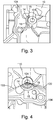
- FIG 3 shows a part perspective view of the ladderframe 10 clearly showing the deflector 15.
- the deflector 15 has an elongate support 16 and a deflection surface 14.
- the deflection surface 14 is arcuate.
- the deflection surface 14 conforms closely to, but does not touch, the metal-to-metal seal 102 in the high pressure oil conduit 101 leading from the laddderframe 10 into the cylinder block 11.
- the deflection surface arc is a circular arc with a radius slightly larger than the radius of the conduit 101.
- the support 16 extends away from the deflection surface 14, initially substantially orthogonally and then curves away to interface with the surface of the ladderframe 10.
- the exact configuration of the support 16 is not critical to the functioning of the deflector 15, the support 16 will be shaped in any way practical to provide the deflection surface 14 in a position to divert the high pressure oil spray away from the gasket seal 104.
- the top part of the deflection surface 14 can be machined if required as a result of process constraints.
- the top of the deflector 15 is machined at the same time as the joint surface 102 of the ladderframe 10. This is due to the proximity between the conduit 101 and the deflector 15 and the size of the cutter. However, in some embodiments, the top surface could be machined separately if it was far enough from the conduit 101. In such a configuration the deflector 15 would be higher than the metal-to-metal seal 102 thereby optimising protection of the RTV.
- the deflection surface 14 illustrated in Figure 3 has a substantially constant cross sectional area, tapering slightly at the ends. This delivers the required deflection of the oil, with a minimal addition to the overall weight of the ladderframe 10. However, it would also be understood that the thickness of the deflection surface 14 could vary whilst still allowing the deflection surface 14 to function as required.
- the deflection surface 14 illustrated in Figure 3 has an arcuate shape with a substantially constant angle of curvature.
- the curvature may be non-uniform or even non-existent.
- the curvature may be modified in order to guide the oil incident on the deflection surface back to the oil sump (not shown).
- Figure 4 shows an end view of the conduit 101 with the deflection surface 14 diverting incident oil 120 to protect the gasket seal 104.
Landscapes
- Engineering & Computer Science (AREA)
- General Engineering & Computer Science (AREA)
- Mechanical Engineering (AREA)
- Chemical & Material Sciences (AREA)
- Combustion & Propulsion (AREA)
- Physics & Mathematics (AREA)
- Geometry (AREA)
- Gasket Seals (AREA)
- Lubrication Details And Ventilation Of Internal Combustion Engines (AREA)
- Heating, Cooling, Or Curing Plastics Or The Like In General (AREA)
- Arrangement Or Mounting Of Propulsion Units For Vehicles (AREA)
- Body Structure For Vehicles (AREA)
Abstract
Description
- This invention relates to improvements in or relating to the use of features intended to control the flow of oil within a vehicle engine, and in particular to the deflection of flow of oil.
- Metal-to-metal seals are deployed in various locations within automotive systems, typically for internal seals in parts of the system where there is some tolerance of imperfection, that is, where the seal may still perform its required function despite being less than 100% effective.
- For example, the oil connections in the low end of an engine which are internal to the engine may still function effectively where seals are less than perfect, because oil escaping through these seals will drain back to the oil sump. The oil can safely drain back to the oil sump without exiting the engine. Therefore there is no detrimental effect on the perceived quality of the engine which will continue to run, but the fuel consumption of the engine will increase and the pumping requirements will also increase. It therefore remains the aim to maximise the efficiency of sealing throughout the engine.
- When a metal-to-metal seal starts to leak, it can result in a jet of oil spraying from the leak point. If the conduit containing the seal is a high pressure conduit, then the oil may be at high pressure. This oil can cause damage to adjacent seals, particularly those formed from room temperature vulcanising (RTV) silicone rubber.
- It is against this background that the present invention has arisen.
- According to the present invention there is provided a ladderframe configured to provide a deflection surface positioned to guide high pressure oil away from adjacent RTV seals. If high pressure oil is incident directly on RTV seals, the oil will cause the seal to fail over time. The deflection surface is configured to divert the high pressure oil to prevent it from landing directly on the seal. In this way the integrity of the seal is preserved and with it the efficiency of the engine and the user's perception of the quality of the engine.
- The deflection surface may be integral with the ladderframe so that the provision of the deflection surface does not entail any additional manufacturing steps or components. The ladderframe, including the deflection surface, may be provided as a cast part. Casting can achieve the complex geometries required to provide the ladderframe with the deflection surface in a single manufacture step.
- The deflection surface may be arcuate. An arcuate deflection surface will guide oil incident thereon to flow safely back to the oil sump without being incident on the RTV seals.
- At least part of the deflection surface, in particular the top part of the deflection surface can be machined if required by the process.
- The invention will now be further and more particularly described, by way of example only, and with reference to the accompanying drawings, in which:
-
Figure 1 shows a cross section through a prior art ladderframe and highlights the area of concern; -
Figure 2 shows a cross section through a ladderframe according to the present invention; -
Figure 3 shows a perspective view of a deflection surface; and -
Figure 4 shows how the deflection surface would operate in accordance with the present invention. -
Figure 1 shows aladderframe 100 andcylinder block 110. There are two seals between theladderframe 100 and the cylinder block 110: a metal-to-metal seal 102 is provided midway along a highpressure oil conduit 101 adjacent to theinner engine 106 and agasket seal 104 is provided at the interface further from theinner engine 106. - A metal-to-
metal seal 102 is chosen for the inner seal because if the seal fails then oil escaping from theconduit 101 between theladderframe 100 and thecylinder block 110 will drain back into an oil sump (not shown). Whilst this will have some negative impact in terms of efficiency of the engine, failure of this seal cannot directly result in the oil exiting the engine and thereby damaging the users' perception of the engine overall. As a metal-to-metal seal is more economical to implement due to the lack of additional parts or additional sealant application being required during assembly and as it has limited negative impact in the case of failure, it is preferred for this location. - A
gasket seal 104 is provided at the interface further from theinner engine 106. A gasket seal includes an additional part, typically in the form of a room temperature vulcanising (RTV) gasket or O-ring which ensures that no oil leaks. This is particularly important at this location because oil leaking from this seal would not naturally drain back to the oil sump and could exit the engine, adversely affecting the users' perception of the engine. -
Figure 1 shows the path taken byoil 120 in the situation where the metal-to-metal seal 102 has failed. Theoil 120 is incident on thegasket seal 104. Theoil 120 is at high pressure and could compromise the integrity of thegasket seal 104. This therefore creates an area ofconcern 130. If thehigh pressure oil 120 did damage thegasket seal 104 then oil could seep from the engine in the direction marked by arrow A. -
Figure 2 shows the same cross section through aladderframe 10 andcylinder block 11 asFigure 1 , but theladderframe 10 shown inFigure 2 is provided with adeflection surface 15. Thedeflector 15 is integral with theladderframe 10. Theladderframe 10 is a cast part and thedeflector 15 is produced as part of the casting process. - The
deflector 15 includes asupport 16 and adeflection surface 14. Thedeflector 15 disrupts theoil 120 spraying from the metal-to-metal seal 102 and diverts it back towards the oil sump (not shown). As will be readily apparent fromFigure 2 , thegasket seal 104 is no longer in the path ofoil 120 spraying from the metal-to-metal seal 102. -
Figure 3 shows a part perspective view of theladderframe 10 clearly showing thedeflector 15. Thedeflector 15 has anelongate support 16 and adeflection surface 14. Thedeflection surface 14 is arcuate. Thedeflection surface 14 conforms closely to, but does not touch, the metal-to-metal seal 102 in the highpressure oil conduit 101 leading from theladdderframe 10 into thecylinder block 11. The deflection surface arc is a circular arc with a radius slightly larger than the radius of theconduit 101. Thesupport 16 extends away from thedeflection surface 14, initially substantially orthogonally and then curves away to interface with the surface of theladderframe 10. The exact configuration of thesupport 16 is not critical to the functioning of thedeflector 15, thesupport 16 will be shaped in any way practical to provide thedeflection surface 14 in a position to divert the high pressure oil spray away from thegasket seal 104. - The top part of the
deflection surface 14 can be machined if required as a result of process constraints. In the illustrated embodiment, the top of thedeflector 15 is machined at the same time as thejoint surface 102 of theladderframe 10. This is due to the proximity between theconduit 101 and thedeflector 15 and the size of the cutter. However, in some embodiments, the top surface could be machined separately if it was far enough from theconduit 101. In such a configuration thedeflector 15 would be higher than the metal-to-metal seal 102 thereby optimising protection of the RTV. - The
deflection surface 14 illustrated inFigure 3 has a substantially constant cross sectional area, tapering slightly at the ends. This delivers the required deflection of the oil, with a minimal addition to the overall weight of theladderframe 10. However, it would also be understood that the thickness of thedeflection surface 14 could vary whilst still allowing thedeflection surface 14 to function as required. - The
deflection surface 14 illustrated inFigure 3 has an arcuate shape with a substantially constant angle of curvature. However, in other embodiments not illustrated in the accompanying drawings, the curvature may be non-uniform or even non-existent. The curvature may be modified in order to guide the oil incident on the deflection surface back to the oil sump (not shown). -
Figure 4 shows an end view of theconduit 101 with thedeflection surface 14 divertingincident oil 120 to protect thegasket seal 104. - It will further be appreciated by those skilled in the art that although the invention has been described by way of example with reference to several embodiments it is not limited to the disclosed embodiments and that alternative embodiments could be constructed without departing from the scope of the invention as defined in the appended claims.
Claims (5)
- A ladderframe configured to provide a deflection surface positioned to guide high pressure oil away from adjacent RTV seals.
- The ladderframe according to claim 1, wherein the deflection surface is integral with the ladderframe.
- The ladderframe according to claim 1 or claim 2, wherein the ladderframe, including the deflection surface, is fabricated by casting.
- The ladderframe according to any one of claims 1 to 3, wherein the deflection surface is arcuate.
- The ladderframe according to any one of claims 1 to 4, wherein at least part of the deflection surface is machined.
Applications Claiming Priority (1)
| Application Number | Priority Date | Filing Date | Title |
|---|---|---|---|
| GB1609835.2A GB2537762B (en) | 2016-06-06 | 2016-06-06 | Improvements in or relating to oil flow control by deflection |
Publications (2)
| Publication Number | Publication Date |
|---|---|
| EP3255333A1 true EP3255333A1 (en) | 2017-12-13 |
| EP3255333B1 EP3255333B1 (en) | 2023-04-05 |
Family
ID=56508114
Family Applications (1)
| Application Number | Title | Priority Date | Filing Date |
|---|---|---|---|
| EP17174431.1A Active EP3255333B1 (en) | 2016-06-06 | 2017-06-05 | Improvements in or relating to oil flow control by deflection |
Country Status (6)
| Country | Link |
|---|---|
| US (2) | US10364772B2 (en) |
| EP (1) | EP3255333B1 (en) |
| CN (1) | CN107461274B (en) |
| GB (1) | GB2537762B (en) |
| MX (1) | MX2017007149A (en) |
| RU (1) | RU2017117322A (en) |
Families Citing this family (1)
| Publication number | Priority date | Publication date | Assignee | Title |
|---|---|---|---|---|
| CN115388315B (en) * | 2022-09-02 | 2024-08-06 | 中国航发贵阳发动机设计研究所 | Oil collecting tank structure for aero-engine |
Citations (4)
| Publication number | Priority date | Publication date | Assignee | Title |
|---|---|---|---|---|
| JPS5571038U (en) * | 1978-11-10 | 1980-05-16 | ||
| JPS55116837U (en) * | 1979-02-13 | 1980-08-18 | ||
| JP2008133809A (en) * | 2006-11-29 | 2008-06-12 | Toyota Industries Corp | Cylinder block for internal combustion engine |
| JP2010138702A (en) * | 2008-12-09 | 2010-06-24 | Toyota Motor Corp | Seal structure of joint of three members |
Family Cites Families (17)
| Publication number | Priority date | Publication date | Assignee | Title |
|---|---|---|---|---|
| JPH08135458A (en) | 1994-11-09 | 1996-05-28 | Toyota Motor Corp | Supercharger oil seal structure |
| JPH08177446A (en) * | 1994-12-27 | 1996-07-09 | Nissan Motor Co Ltd | Crank support device for internal combustion engine |
| JP3712865B2 (en) * | 1998-08-12 | 2005-11-02 | 本田技研工業株式会社 | Reciprocating device for reciprocating piston engine |
| US6155431A (en) * | 1999-05-03 | 2000-12-05 | Honeywell International Inc. | Filter assembly |
| US6626714B2 (en) * | 2001-01-31 | 2003-09-30 | Sanshin Kogyo Kabushiki Kaisha | Oil pump arrangement for marine drive |
| US6912985B2 (en) | 2002-12-18 | 2005-07-05 | Micron Technology, Inc. | Oil deflector apparatus |
| JP2004245081A (en) * | 2003-02-12 | 2004-09-02 | Suzuki Motor Corp | Oil pump relief valve structure |
| JP2005113822A (en) * | 2003-10-09 | 2005-04-28 | Sanwa Packing Kogyo Co Ltd | Head cover construction of engine having vibration damping property |
| MXPA06007493A (en) | 2004-01-28 | 2007-04-17 | New Condensator Inc | Apparatus for removing contaminants from crankcase emissions. |
| US8066100B2 (en) * | 2004-10-05 | 2011-11-29 | Toyota Jidosha Kabushiki Kaisha | Oil pan and lubricating device |
| JP5381502B2 (en) * | 2009-08-25 | 2014-01-08 | トヨタ自動車株式会社 | Seal structure using liquid gasket |
| DE102009057667A1 (en) * | 2009-12-09 | 2011-06-16 | Daimler Ag | Internal combustion engine has crankcase, where cylinder head is connected to crankcase over cylinder head gasket, and vacuum reservoir is integrated in crankcase or in cylinder head |
| WO2013179643A1 (en) | 2012-05-31 | 2013-12-05 | 日野自動車株式会社 | Bearing structure |
| EP2872753B1 (en) * | 2012-07-15 | 2019-03-20 | Garrett Transportation I Inc. | Turbocharger with lubricant deflector |
| EP3705703B1 (en) * | 2013-03-15 | 2023-09-13 | Raytheon Technologies Corporation | Shield for arranging between a bearing and a rotating seal element |
| JP6134239B2 (en) * | 2013-09-13 | 2017-05-24 | 日立オートモティブシステムズ株式会社 | Housing for balancer device of internal combustion engine and method for assembling balancer device |
| JP6028713B2 (en) | 2013-10-28 | 2016-11-16 | トヨタ自動車株式会社 | Turbocharger oil drain structure |
-
2016
- 2016-06-06 GB GB1609835.2A patent/GB2537762B/en not_active Expired - Fee Related
-
2017
- 2017-05-18 RU RU2017117322A patent/RU2017117322A/en not_active Application Discontinuation
- 2017-05-31 US US15/609,521 patent/US10364772B2/en active Active
- 2017-06-02 CN CN201710407470.3A patent/CN107461274B/en active Active
- 2017-06-05 EP EP17174431.1A patent/EP3255333B1/en active Active
- 2017-06-05 MX MX2017007149A patent/MX2017007149A/en unknown
-
2019
- 2019-05-31 US US16/427,601 patent/US10508616B2/en active Active
Patent Citations (4)
| Publication number | Priority date | Publication date | Assignee | Title |
|---|---|---|---|---|
| JPS5571038U (en) * | 1978-11-10 | 1980-05-16 | ||
| JPS55116837U (en) * | 1979-02-13 | 1980-08-18 | ||
| JP2008133809A (en) * | 2006-11-29 | 2008-06-12 | Toyota Industries Corp | Cylinder block for internal combustion engine |
| JP2010138702A (en) * | 2008-12-09 | 2010-06-24 | Toyota Motor Corp | Seal structure of joint of three members |
Also Published As
| Publication number | Publication date |
|---|---|
| GB2537762A (en) | 2016-10-26 |
| CN107461274A (en) | 2017-12-12 |
| EP3255333B1 (en) | 2023-04-05 |
| GB201609835D0 (en) | 2016-07-20 |
| US20190285025A1 (en) | 2019-09-19 |
| CN107461274B (en) | 2021-05-25 |
| RU2017117322A (en) | 2018-11-19 |
| US20170350347A1 (en) | 2017-12-07 |
| GB2537762B (en) | 2020-04-22 |
| MX2017007149A (en) | 2018-08-28 |
| US10364772B2 (en) | 2019-07-30 |
| US10508616B2 (en) | 2019-12-17 |
Similar Documents
| Publication | Publication Date | Title |
|---|---|---|
| EP3473931B1 (en) | Assembly for gas turbine engine comprising an injector and an engine case | |
| US8328203B2 (en) | Sealing system for exhaust-gas lines | |
| JP6575606B2 (en) | Valve stem seal | |
| JP4267433B2 (en) | Combustion gas seal for fuel injection valve | |
| US20180156130A1 (en) | Aircraft seal structure and aircraft | |
| EP3957842A1 (en) | Aircraft firewall feedthrough device | |
| CN108952851B (en) | Masking fixtures | |
| EP1923561B1 (en) | Gasket with leak conduit | |
| EP3255333A1 (en) | Improvements in or relating to oil flow control by deflection | |
| US8529200B2 (en) | Sealing and purging arrangement for a main bearing region | |
| EP2899434A1 (en) | Gasket structure in internal combustion engine | |
| EP3236113B1 (en) | Improvements in or relating to metal-to-metal sealing | |
| US10947860B2 (en) | Actuator | |
| US9664162B2 (en) | Sealing structure | |
| KR20170108166A (en) | Motor/pump unit having a single elastic diaphragm | |
| US10401921B2 (en) | Protective case for a computer and method for manufacturing such a case | |
| CN108952826A (en) | Pneumatic elasticity densification device and gas-turbine unit | |
| CN100402883C (en) | Non-leak hydraulic damper | |
| US20130200570A1 (en) | Carbon seal o-ring cavity sizing | |
| US10359070B2 (en) | Seal structure and control cable unit | |
| EP3137793B1 (en) | Pressure controlled dynamic seal with captured fluid transfer tubes | |
| KR102394774B1 (en) | Device for sealing T-joint part between cylinder block and oil pan | |
| EP0792772B1 (en) | Fluid reservoir protection sleeve | |
| EP1854994B1 (en) | Protective device for terminations of pipes carrying fluids under pressure in an engine, especially for marine or special applications | |
| JP4851101B2 (en) | gasket |
Legal Events
| Date | Code | Title | Description |
|---|---|---|---|
| PUAI | Public reference made under article 153(3) epc to a published international application that has entered the european phase |
Free format text: ORIGINAL CODE: 0009012 |
|
| STAA | Information on the status of an ep patent application or granted ep patent |
Free format text: STATUS: THE APPLICATION HAS BEEN PUBLISHED |
|
| AK | Designated contracting states |
Kind code of ref document: A1 Designated state(s): AL AT BE BG CH CY CZ DE DK EE ES FI FR GB GR HR HU IE IS IT LI LT LU LV MC MK MT NL NO PL PT RO RS SE SI SK SM TR |
|
| AX | Request for extension of the european patent |
Extension state: BA ME |
|
| STAA | Information on the status of an ep patent application or granted ep patent |
Free format text: STATUS: REQUEST FOR EXAMINATION WAS MADE |
|
| 17P | Request for examination filed |
Effective date: 20180613 |
|
| RBV | Designated contracting states (corrected) |
Designated state(s): AL AT BE BG CH CY CZ DE DK EE ES FI FR GB GR HR HU IE IS IT LI LT LU LV MC MK MT NL NO PL PT RO RS SE SI SK SM TR |
|
| STAA | Information on the status of an ep patent application or granted ep patent |
Free format text: STATUS: EXAMINATION IS IN PROGRESS |
|
| 17Q | First examination report despatched |
Effective date: 20210701 |
|
| GRAP | Despatch of communication of intention to grant a patent |
Free format text: ORIGINAL CODE: EPIDOSNIGR1 |
|
| STAA | Information on the status of an ep patent application or granted ep patent |
Free format text: STATUS: GRANT OF PATENT IS INTENDED |
|
| RIC1 | Information provided on ipc code assigned before grant |
Ipc: F02F 7/00 20060101ALN20220920BHEP Ipc: F16J 15/06 20060101ALI20220920BHEP Ipc: F02F 11/00 20060101ALI20220920BHEP Ipc: F16N 31/02 20060101AFI20220920BHEP |
|
| INTG | Intention to grant announced |
Effective date: 20221010 |
|
| GRAS | Grant fee paid |
Free format text: ORIGINAL CODE: EPIDOSNIGR3 |
|
| GRAA | (expected) grant |
Free format text: ORIGINAL CODE: 0009210 |
|
| STAA | Information on the status of an ep patent application or granted ep patent |
Free format text: STATUS: THE PATENT HAS BEEN GRANTED |
|
| AK | Designated contracting states |
Kind code of ref document: B1 Designated state(s): AL AT BE BG CH CY CZ DE DK EE ES FI FR GB GR HR HU IE IS IT LI LT LU LV MC MK MT NL NO PL PT RO RS SE SI SK SM TR |
|
| REG | Reference to a national code |
Ref country code: GB Ref legal event code: FG4D |
|
| REG | Reference to a national code |
Ref country code: CH Ref legal event code: EP |
|
| REG | Reference to a national code |
Ref country code: AT Ref legal event code: REF Ref document number: 1558472 Country of ref document: AT Kind code of ref document: T Effective date: 20230415 |
|
| REG | Reference to a national code |
Ref country code: DE Ref legal event code: R096 Ref document number: 602017067385 Country of ref document: DE |
|
| REG | Reference to a national code |
Ref country code: IE Ref legal event code: FG4D |
|
| REG | Reference to a national code |
Ref country code: LT Ref legal event code: MG9D |
|
| P01 | Opt-out of the competence of the unified patent court (upc) registered |
Effective date: 20230620 |
|
| REG | Reference to a national code |
Ref country code: NL Ref legal event code: MP Effective date: 20230405 |
|
| REG | Reference to a national code |
Ref country code: AT Ref legal event code: MK05 Ref document number: 1558472 Country of ref document: AT Kind code of ref document: T Effective date: 20230405 |
|
| PG25 | Lapsed in a contracting state [announced via postgrant information from national office to epo] |
Ref country code: NL Free format text: LAPSE BECAUSE OF FAILURE TO SUBMIT A TRANSLATION OF THE DESCRIPTION OR TO PAY THE FEE WITHIN THE PRESCRIBED TIME-LIMIT Effective date: 20230405 |
|
| PG25 | Lapsed in a contracting state [announced via postgrant information from national office to epo] |
Ref country code: SE Free format text: LAPSE BECAUSE OF FAILURE TO SUBMIT A TRANSLATION OF THE DESCRIPTION OR TO PAY THE FEE WITHIN THE PRESCRIBED TIME-LIMIT Effective date: 20230405 Ref country code: PT Free format text: LAPSE BECAUSE OF FAILURE TO SUBMIT A TRANSLATION OF THE DESCRIPTION OR TO PAY THE FEE WITHIN THE PRESCRIBED TIME-LIMIT Effective date: 20230807 Ref country code: NO Free format text: LAPSE BECAUSE OF FAILURE TO SUBMIT A TRANSLATION OF THE DESCRIPTION OR TO PAY THE FEE WITHIN THE PRESCRIBED TIME-LIMIT Effective date: 20230705 Ref country code: ES Free format text: LAPSE BECAUSE OF FAILURE TO SUBMIT A TRANSLATION OF THE DESCRIPTION OR TO PAY THE FEE WITHIN THE PRESCRIBED TIME-LIMIT Effective date: 20230405 Ref country code: AT Free format text: LAPSE BECAUSE OF FAILURE TO SUBMIT A TRANSLATION OF THE DESCRIPTION OR TO PAY THE FEE WITHIN THE PRESCRIBED TIME-LIMIT Effective date: 20230405 |
|
| PG25 | Lapsed in a contracting state [announced via postgrant information from national office to epo] |
Ref country code: RS Free format text: LAPSE BECAUSE OF FAILURE TO SUBMIT A TRANSLATION OF THE DESCRIPTION OR TO PAY THE FEE WITHIN THE PRESCRIBED TIME-LIMIT Effective date: 20230405 Ref country code: PL Free format text: LAPSE BECAUSE OF FAILURE TO SUBMIT A TRANSLATION OF THE DESCRIPTION OR TO PAY THE FEE WITHIN THE PRESCRIBED TIME-LIMIT Effective date: 20230405 Ref country code: LV Free format text: LAPSE BECAUSE OF FAILURE TO SUBMIT A TRANSLATION OF THE DESCRIPTION OR TO PAY THE FEE WITHIN THE PRESCRIBED TIME-LIMIT Effective date: 20230405 Ref country code: LT Free format text: LAPSE BECAUSE OF FAILURE TO SUBMIT A TRANSLATION OF THE DESCRIPTION OR TO PAY THE FEE WITHIN THE PRESCRIBED TIME-LIMIT Effective date: 20230405 Ref country code: IS Free format text: LAPSE BECAUSE OF FAILURE TO SUBMIT A TRANSLATION OF THE DESCRIPTION OR TO PAY THE FEE WITHIN THE PRESCRIBED TIME-LIMIT Effective date: 20230805 Ref country code: HR Free format text: LAPSE BECAUSE OF FAILURE TO SUBMIT A TRANSLATION OF THE DESCRIPTION OR TO PAY THE FEE WITHIN THE PRESCRIBED TIME-LIMIT Effective date: 20230405 Ref country code: GR Free format text: LAPSE BECAUSE OF FAILURE TO SUBMIT A TRANSLATION OF THE DESCRIPTION OR TO PAY THE FEE WITHIN THE PRESCRIBED TIME-LIMIT Effective date: 20230706 Ref country code: AL Free format text: LAPSE BECAUSE OF FAILURE TO SUBMIT A TRANSLATION OF THE DESCRIPTION OR TO PAY THE FEE WITHIN THE PRESCRIBED TIME-LIMIT Effective date: 20230405 |
|
| PG25 | Lapsed in a contracting state [announced via postgrant information from national office to epo] |
Ref country code: FI Free format text: LAPSE BECAUSE OF FAILURE TO SUBMIT A TRANSLATION OF THE DESCRIPTION OR TO PAY THE FEE WITHIN THE PRESCRIBED TIME-LIMIT Effective date: 20230405 |
|
| REG | Reference to a national code |
Ref country code: DE Ref legal event code: R097 Ref document number: 602017067385 Country of ref document: DE |
|
| PG25 | Lapsed in a contracting state [announced via postgrant information from national office to epo] |
Ref country code: SK Free format text: LAPSE BECAUSE OF FAILURE TO SUBMIT A TRANSLATION OF THE DESCRIPTION OR TO PAY THE FEE WITHIN THE PRESCRIBED TIME-LIMIT Effective date: 20230405 |
|
| PG25 | Lapsed in a contracting state [announced via postgrant information from national office to epo] |
Ref country code: MC Free format text: LAPSE BECAUSE OF FAILURE TO SUBMIT A TRANSLATION OF THE DESCRIPTION OR TO PAY THE FEE WITHIN THE PRESCRIBED TIME-LIMIT Effective date: 20230405 |
|
| PG25 | Lapsed in a contracting state [announced via postgrant information from national office to epo] |
Ref country code: SM Free format text: LAPSE BECAUSE OF FAILURE TO SUBMIT A TRANSLATION OF THE DESCRIPTION OR TO PAY THE FEE WITHIN THE PRESCRIBED TIME-LIMIT Effective date: 20230405 Ref country code: SK Free format text: LAPSE BECAUSE OF FAILURE TO SUBMIT A TRANSLATION OF THE DESCRIPTION OR TO PAY THE FEE WITHIN THE PRESCRIBED TIME-LIMIT Effective date: 20230405 Ref country code: RO Free format text: LAPSE BECAUSE OF FAILURE TO SUBMIT A TRANSLATION OF THE DESCRIPTION OR TO PAY THE FEE WITHIN THE PRESCRIBED TIME-LIMIT Effective date: 20230405 Ref country code: MC Free format text: LAPSE BECAUSE OF FAILURE TO SUBMIT A TRANSLATION OF THE DESCRIPTION OR TO PAY THE FEE WITHIN THE PRESCRIBED TIME-LIMIT Effective date: 20230405 Ref country code: EE Free format text: LAPSE BECAUSE OF FAILURE TO SUBMIT A TRANSLATION OF THE DESCRIPTION OR TO PAY THE FEE WITHIN THE PRESCRIBED TIME-LIMIT Effective date: 20230405 Ref country code: DK Free format text: LAPSE BECAUSE OF FAILURE TO SUBMIT A TRANSLATION OF THE DESCRIPTION OR TO PAY THE FEE WITHIN THE PRESCRIBED TIME-LIMIT Effective date: 20230405 Ref country code: CZ Free format text: LAPSE BECAUSE OF FAILURE TO SUBMIT A TRANSLATION OF THE DESCRIPTION OR TO PAY THE FEE WITHIN THE PRESCRIBED TIME-LIMIT Effective date: 20230405 |
|
| REG | Reference to a national code |
Ref country code: CH Ref legal event code: PL |
|
| PLBE | No opposition filed within time limit |
Free format text: ORIGINAL CODE: 0009261 |
|
| STAA | Information on the status of an ep patent application or granted ep patent |
Free format text: STATUS: NO OPPOSITION FILED WITHIN TIME LIMIT |
|
| REG | Reference to a national code |
Ref country code: BE Ref legal event code: MM Effective date: 20230630 |
|
| PG25 | Lapsed in a contracting state [announced via postgrant information from national office to epo] |
Ref country code: LU Free format text: LAPSE BECAUSE OF NON-PAYMENT OF DUE FEES Effective date: 20230605 |
|
| 26N | No opposition filed |
Effective date: 20240108 |
|
| REG | Reference to a national code |
Ref country code: IE Ref legal event code: MM4A |
|
| PG25 | Lapsed in a contracting state [announced via postgrant information from national office to epo] |
Ref country code: LU Free format text: LAPSE BECAUSE OF NON-PAYMENT OF DUE FEES Effective date: 20230605 |
|
| PG25 | Lapsed in a contracting state [announced via postgrant information from national office to epo] |
Ref country code: IE Free format text: LAPSE BECAUSE OF NON-PAYMENT OF DUE FEES Effective date: 20230605 |
|
| PG25 | Lapsed in a contracting state [announced via postgrant information from national office to epo] |
Ref country code: IE Free format text: LAPSE BECAUSE OF NON-PAYMENT OF DUE FEES Effective date: 20230605 Ref country code: CH Free format text: LAPSE BECAUSE OF NON-PAYMENT OF DUE FEES Effective date: 20230630 |
|
| PG25 | Lapsed in a contracting state [announced via postgrant information from national office to epo] |
Ref country code: SI Free format text: LAPSE BECAUSE OF FAILURE TO SUBMIT A TRANSLATION OF THE DESCRIPTION OR TO PAY THE FEE WITHIN THE PRESCRIBED TIME-LIMIT Effective date: 20230405 |
|
| PG25 | Lapsed in a contracting state [announced via postgrant information from national office to epo] |
Ref country code: SI Free format text: LAPSE BECAUSE OF FAILURE TO SUBMIT A TRANSLATION OF THE DESCRIPTION OR TO PAY THE FEE WITHIN THE PRESCRIBED TIME-LIMIT Effective date: 20230405 Ref country code: IT Free format text: LAPSE BECAUSE OF FAILURE TO SUBMIT A TRANSLATION OF THE DESCRIPTION OR TO PAY THE FEE WITHIN THE PRESCRIBED TIME-LIMIT Effective date: 20230405 Ref country code: FR Free format text: LAPSE BECAUSE OF NON-PAYMENT OF DUE FEES Effective date: 20230605 Ref country code: BE Free format text: LAPSE BECAUSE OF NON-PAYMENT OF DUE FEES Effective date: 20230630 |
|
| PG25 | Lapsed in a contracting state [announced via postgrant information from national office to epo] |
Ref country code: BG Free format text: LAPSE BECAUSE OF FAILURE TO SUBMIT A TRANSLATION OF THE DESCRIPTION OR TO PAY THE FEE WITHIN THE PRESCRIBED TIME-LIMIT Effective date: 20230405 |
|
| PG25 | Lapsed in a contracting state [announced via postgrant information from national office to epo] |
Ref country code: BG Free format text: LAPSE BECAUSE OF FAILURE TO SUBMIT A TRANSLATION OF THE DESCRIPTION OR TO PAY THE FEE WITHIN THE PRESCRIBED TIME-LIMIT Effective date: 20230405 |
|
| PGFP | Annual fee paid to national office [announced via postgrant information from national office to epo] |
Ref country code: DE Payment date: 20250509 Year of fee payment: 9 |
|
| PGFP | Annual fee paid to national office [announced via postgrant information from national office to epo] |
Ref country code: GB Payment date: 20250508 Year of fee payment: 9 |
|
| PG25 | Lapsed in a contracting state [announced via postgrant information from national office to epo] |
Ref country code: CY Free format text: LAPSE BECAUSE OF FAILURE TO SUBMIT A TRANSLATION OF THE DESCRIPTION OR TO PAY THE FEE WITHIN THE PRESCRIBED TIME-LIMIT; INVALID AB INITIO Effective date: 20170605 |
|
| PG25 | Lapsed in a contracting state [announced via postgrant information from national office to epo] |
Ref country code: HU Free format text: LAPSE BECAUSE OF FAILURE TO SUBMIT A TRANSLATION OF THE DESCRIPTION OR TO PAY THE FEE WITHIN THE PRESCRIBED TIME-LIMIT; INVALID AB INITIO Effective date: 20170605 |
|
| PG25 | Lapsed in a contracting state [announced via postgrant information from national office to epo] |
Ref country code: TR Free format text: LAPSE BECAUSE OF FAILURE TO SUBMIT A TRANSLATION OF THE DESCRIPTION OR TO PAY THE FEE WITHIN THE PRESCRIBED TIME-LIMIT Effective date: 20230405 |