EP3255326A1 - Double walled tube and manufacture thereof - Google Patents
Double walled tube and manufacture thereof Download PDFInfo
- Publication number
- EP3255326A1 EP3255326A1 EP17174631.6A EP17174631A EP3255326A1 EP 3255326 A1 EP3255326 A1 EP 3255326A1 EP 17174631 A EP17174631 A EP 17174631A EP 3255326 A1 EP3255326 A1 EP 3255326A1
- Authority
- EP
- European Patent Office
- Prior art keywords
- tube
- spacer
- coupled
- segment
- segments
- Prior art date
- Legal status (The legal status is an assumption and is not a legal conclusion. Google has not performed a legal analysis and makes no representation as to the accuracy of the status listed.)
- Granted
Links
Images







Classifications
-
- F—MECHANICAL ENGINEERING; LIGHTING; HEATING; WEAPONS; BLASTING
- F16—ENGINEERING ELEMENTS AND UNITS; GENERAL MEASURES FOR PRODUCING AND MAINTAINING EFFECTIVE FUNCTIONING OF MACHINES OR INSTALLATIONS; THERMAL INSULATION IN GENERAL
- F16L—PIPES; JOINTS OR FITTINGS FOR PIPES; SUPPORTS FOR PIPES, CABLES OR PROTECTIVE TUBING; MEANS FOR THERMAL INSULATION IN GENERAL
- F16L9/00—Rigid pipes
- F16L9/18—Double-walled pipes; Multi-channel pipes or pipe assemblies
-
- F—MECHANICAL ENGINEERING; LIGHTING; HEATING; WEAPONS; BLASTING
- F01—MACHINES OR ENGINES IN GENERAL; ENGINE PLANTS IN GENERAL; STEAM ENGINES
- F01D—NON-POSITIVE DISPLACEMENT MACHINES OR ENGINES, e.g. STEAM TURBINES
- F01D25/00—Component parts, details, or accessories, not provided for in, or of interest apart from, other groups
-
- F—MECHANICAL ENGINEERING; LIGHTING; HEATING; WEAPONS; BLASTING
- F01—MACHINES OR ENGINES IN GENERAL; ENGINE PLANTS IN GENERAL; STEAM ENGINES
- F01D—NON-POSITIVE DISPLACEMENT MACHINES OR ENGINES, e.g. STEAM TURBINES
- F01D25/00—Component parts, details, or accessories, not provided for in, or of interest apart from, other groups
- F01D25/18—Lubricating arrangements
-
- F—MECHANICAL ENGINEERING; LIGHTING; HEATING; WEAPONS; BLASTING
- F02—COMBUSTION ENGINES; HOT-GAS OR COMBUSTION-PRODUCT ENGINE PLANTS
- F02C—GAS-TURBINE PLANTS; AIR INTAKES FOR JET-PROPULSION PLANTS; CONTROLLING FUEL SUPPLY IN AIR-BREATHING JET-PROPULSION PLANTS
- F02C7/00—Features, components parts, details or accessories, not provided for in, or of interest apart form groups F02C1/00 - F02C6/00; Air intakes for jet-propulsion plants
-
- F—MECHANICAL ENGINEERING; LIGHTING; HEATING; WEAPONS; BLASTING
- F02—COMBUSTION ENGINES; HOT-GAS OR COMBUSTION-PRODUCT ENGINE PLANTS
- F02C—GAS-TURBINE PLANTS; AIR INTAKES FOR JET-PROPULSION PLANTS; CONTROLLING FUEL SUPPLY IN AIR-BREATHING JET-PROPULSION PLANTS
- F02C7/00—Features, components parts, details or accessories, not provided for in, or of interest apart form groups F02C1/00 - F02C6/00; Air intakes for jet-propulsion plants
- F02C7/22—Fuel supply systems
- F02C7/222—Fuel flow conduits, e.g. manifolds
-
- F—MECHANICAL ENGINEERING; LIGHTING; HEATING; WEAPONS; BLASTING
- F02—COMBUSTION ENGINES; HOT-GAS OR COMBUSTION-PRODUCT ENGINE PLANTS
- F02C—GAS-TURBINE PLANTS; AIR INTAKES FOR JET-PROPULSION PLANTS; CONTROLLING FUEL SUPPLY IN AIR-BREATHING JET-PROPULSION PLANTS
- F02C7/00—Features, components parts, details or accessories, not provided for in, or of interest apart form groups F02C1/00 - F02C6/00; Air intakes for jet-propulsion plants
- F02C7/32—Arrangement, mounting, or driving, of auxiliaries
-
- F—MECHANICAL ENGINEERING; LIGHTING; HEATING; WEAPONS; BLASTING
- F16—ENGINEERING ELEMENTS AND UNITS; GENERAL MEASURES FOR PRODUCING AND MAINTAINING EFFECTIVE FUNCTIONING OF MACHINES OR INSTALLATIONS; THERMAL INSULATION IN GENERAL
- F16L—PIPES; JOINTS OR FITTINGS FOR PIPES; SUPPORTS FOR PIPES, CABLES OR PROTECTIVE TUBING; MEANS FOR THERMAL INSULATION IN GENERAL
- F16L39/00—Joints or fittings for double-walled or multi-channel pipes or pipe assemblies
- F16L39/005—Joints or fittings for double-walled or multi-channel pipes or pipe assemblies for concentric pipes
-
- F—MECHANICAL ENGINEERING; LIGHTING; HEATING; WEAPONS; BLASTING
- F05—INDEXING SCHEMES RELATING TO ENGINES OR PUMPS IN VARIOUS SUBCLASSES OF CLASSES F01-F04
- F05D—INDEXING SCHEME FOR ASPECTS RELATING TO NON-POSITIVE-DISPLACEMENT MACHINES OR ENGINES, GAS-TURBINES OR JET-PROPULSION PLANTS
- F05D2240/00—Components
- F05D2240/40—Use of a multiplicity of similar components
-
- F—MECHANICAL ENGINEERING; LIGHTING; HEATING; WEAPONS; BLASTING
- F16—ENGINEERING ELEMENTS AND UNITS; GENERAL MEASURES FOR PRODUCING AND MAINTAINING EFFECTIVE FUNCTIONING OF MACHINES OR INSTALLATIONS; THERMAL INSULATION IN GENERAL
- F16L—PIPES; JOINTS OR FITTINGS FOR PIPES; SUPPORTS FOR PIPES, CABLES OR PROTECTIVE TUBING; MEANS FOR THERMAL INSULATION IN GENERAL
- F16L2201/00—Special arrangements for pipe couplings
- F16L2201/30—Detecting leaks
-
- F—MECHANICAL ENGINEERING; LIGHTING; HEATING; WEAPONS; BLASTING
- F16—ENGINEERING ELEMENTS AND UNITS; GENERAL MEASURES FOR PRODUCING AND MAINTAINING EFFECTIVE FUNCTIONING OF MACHINES OR INSTALLATIONS; THERMAL INSULATION IN GENERAL
- F16L—PIPES; JOINTS OR FITTINGS FOR PIPES; SUPPORTS FOR PIPES, CABLES OR PROTECTIVE TUBING; MEANS FOR THERMAL INSULATION IN GENERAL
- F16L7/00—Supporting pipes or cables inside other pipes or sleeves, e.g. for enabling pipes or cables to be inserted or withdrawn from under roads or railways without interruption of traffic
Definitions
- Gas turbine engines such as those which power aircraft and industrial equipment, employ a compressor to compress air that is drawn into the engine and a turbine to capture energy associated with the combustion of a fuel-air mixture.
- One or more fluids are typically circulated throughout the engine. For example, oil may be supplied to one or more bearings in order to clean, cool, and lubricate the bearings.
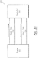
- the fluids are typically conveyed from a fluid source (e.g., an oil tank) 202 to the intended destination (e.g., the bearings or an associated bearing compartment) 206 by a supply tube 210.
- the fluid is then returned from the destination 206 to the source 202 by a return tube 214.
- a closed-loop system 200 is established.
- the tubes may be manufactured as a double walled tube, where the fluid is intended to be conveyed by a first tube 232.
- a second tube 236 serves to contain any fluid that may leak from the first tube 232.
- the double walled tube arrangement shown in FIG. 2B is frequently referred to as a "tube within a tube" as the tube 236 has a larger dimension/diameter than the tube 232 and the tube 232 is contained/nested within the tube 236.
- the tube 232 is an inner tube relative to the outer tube 236.
- a system 250 is shown.
- the system 250 is shown as including five tube assemblies, denoted as assemblies 251, 252, 253, 254, and 255 (it is noted that the assemblies 252 and 253 may be implemented as a single assembly, resulting in four tube assemblies in FIG. 2C ; for purposes of this disclosure, this distinction is of no import and is ignored going forward).
- Each of the assemblies 251-255 may correspond to a double walled arrangement as shown in FIG. 2B .
- the assemblies 251-255 are separated from one another by hardware 261, 262, 263, and 264.
- the hardware 261-264 may support the assemblies 251-255 and provide a location for clamping the tube assembly and mounting the tube assembly to an engine structure (e.g., an engine case).
- the use of the hardware 261-264 represents a penalty/cost in terms of weight and complexity.
- the hardware 261-264 can also weaken/compromise the assemblies 251-255 (e.g., the tube 232 of FIG. 2B ) at the point where the hardware interfaces to the assemblies.
- a tube assembly comprising: a first tube having a radial exterior surface, a second tube composed of a plurality of segments, the first tube co-axially nested within the second tube, at least a first spacer coupled to the first tube, and a second spacer coupled to the at least a first spacer, where a first segment of the plurality of segments is coupled to a first axial end of the second spacer, and a second segment of the plurality of segments is coupled to a second axial end of the second spacer.
- the tube assembly further comprises an end fitting coupled to the first tube.
- the second tube is coupled to the end fitting.
- the tube assembly further comprises a first ferrule coupled to the first tube. In some embodiments, the tube assembly further comprises a second ferrule coupled to the second tube. In some embodiments, a third segment of the plurality of segments is coupled to the second ferrule.
- the at least a first spacer includes a first inner spacer and a second inner spacer. In some embodiments, a first center of the first inner spacer is aligned with a second center of the second inner spacer relative to an axial length of the first tube. In some embodiments, the first center and the second center are separated from one another by approximately one-hundred eighty degrees relative to a circumference of the first tube.
- a first structure of the first inner spacer is separated from a second structure of the second inner spacer by a non-zero value of distance.
- the first tube is configured to convey a fluid.
- the fluid includes at least one of oil, fuel, hydraulic fluid, or air.
- the second tube is configured to convey a second fluid.
- the tube assembly is mounted to an engine of an aircraft.
- aspects of the disclosure are directed to a method comprising: sliding a plurality of outer tube segments onto an inner tube, using an outer spacer to separate a first and a second of the plurality of outer tube segments, attaching at least one inner spacer to the inner tube, attaching the outer spacer to the at least one inner spacer, attaching the outer spacer to the first outer tube segment, and attaching the outer spacer to the second outer tube segment.
- the method further comprises attaching the inner tube to an end fitting.
- the method further comprises attaching the first outer tube segment to the end fitting.
- the method further comprises attaching an inner ferrule to the inner tube.
- the method further comprises attaching an outer ferrule to the second outer tube segment.
- the method further comprises attaching an outer ferrule to a third outer tube segment of the plurality of outer tube segments.
- connections are set forth between elements in the following description and in the drawings (the contents of which are included in this disclosure by way of reference). It is noted that these connections are general and, unless specified otherwise, may be direct or indirect and that this specification is not intended to be limiting in this respect.
- a coupling between two or more entities may refer to a direct connection or an indirect connection.
- An indirect connection may incorporate one or more intervening entities.
- apparatuses, systems, and methods are directed to a double walled arrangement for a tube assembly.
- the tube assembly may include a first, inner tube surrounded by a second, outer tube.
- the outer tube may be composed of segments; the inner tube may be a unitary tube/piece.
- the tube assembly may include one or more spacers to couple the inner tube and the outer tube to one another.
- One or more attachment techniques such as welding or brazing for example, may be used in the manufacture of the tube assembly.
- FIG. 1 is a side cutaway illustration of a geared turbine engine 10.
- This turbine engine 10 extends along an axial centerline 12 between an upstream airflow inlet 14 and a downstream airflow exhaust 16.
- the turbine engine 10 includes a fan section 18, a compressor section 19, a combustor section 20 and a turbine section 21.
- the compressor section 19 includes a low pressure compressor (LPC) section 19A and a high pressure compressor (HPC) section 19B.
- the turbine section 21 includes a high pressure turbine (HPT) section 21A and a low pressure turbine (LPT) section 21B.
- the engine sections 18-21 are arranged sequentially along the centerline 12 within an engine housing 22.
- Each of the engine sections 18-19B, 21A and 21B includes a respective rotor 24-28.
- Each of these rotors 24-28 includes a plurality of rotor blades arranged circumferentially around and connected to one or more respective rotor disks.
- the rotor blades may be formed integral with or mechanically fastened, welded, brazed, adhered and/or otherwise attached to the respective rotor disk(s).
- the fan rotor 24 is connected to a gear train 30, for example, through a fan shaft 32.
- the gear train 30 and the LPC rotor 25 are connected to and driven by the LPT rotor 28 through a low speed shaft 33.
- the HPC rotor 26 is connected to and driven by the HPT rotor 27 through a high speed shaft 34.
- the shafts 32-34 are rotatably supported by a plurality of bearings 36; e.g., rolling element and/or thrust bearings. Each of these bearings 36 is connected to the engine housing 22 by at least one stationary structure such as, for example, an annular support strut.
- the air within the core gas path 38 may be referred to as "core air”.
- the air within the bypass gas path 40 may be referred to as "bypass air”.
- the core air is directed through the engine sections 19-21, and exits the turbine engine 10 through the airflow exhaust 16 to provide forward engine thrust.
- fuel is injected into a combustion chamber 42 and mixed with compressed core air. This fuel-core air mixture is ignited to power the turbine engine 10.
- the bypass air is directed through the bypass gas path 40 and out of the turbine engine 10 through a bypass nozzle 44 to provide additional forward engine thrust. This additional forward engine thrust may account for a majority (e.g., more than 70 percent) of total engine thrust.
- at least some of the bypass air may be directed out of the turbine engine 10 through a thrust reverser to provide reverse engine thrust.
- FIG. 1 represents one possible configuration for an engine 10. Aspects of the disclosure may be applied in connection with other environments, including additional configurations for gas turbine engines. Aspects of the disclosure may be applied in connection with non-geared engines.
- FIGS. 3A-3G various components used in the manufacture of a tube assembly are shown.
- FIGS. 3A-3G illustrate an end fitting 302, an outer tube segment 308, an inner tube 314, a portion of a first (inner) spacer 320, a second (outer) spacer 326, a first (inner) ferrule 332, and a second (outer) ferrule 338, respectively.
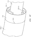
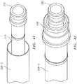
- FIG. 4A-4J illustrate a tube assembly at various stages of manufacture, where the tube assembly is manufactured using the components depicted in FIGS. 3A-3G .
- the manufacture of the tube assembly is further described in relation to the method 500 of FIG. 5 .
- outer tube segments 308-1 and 308 may be slid onto/on top of an inner tube 314.
- Outer spacers 326 may be used to separate the segments 308-1 and 308 from one another.
- the inner tube 314 may be attached (e.g., welded) to an end fitting 302.
- the outer tube segment 308-1 may be attached (e.g., welded) to the end fitting 302.
- two inner spacers 320-1 and 320-2 may be attached (e.g., welded) to the inner tube 314.
- the respective centers of the spacers 320-1 and 320-2 may be substantially aligned with one another relative to an axial length of the inner tube 314 and separated from one another by approximately one-hundred eighty degrees relative to a circumference of the inner tube 314.
- the structures of the spacers 320-1 and 320-2 may be separated from one another by a distance 420.
- any non-zero value of the distance 420 may allow any fluid that escapes from/leaks out of the inner tube 314 to traverse the region between the inner pipe 314 and the outer pipe (or the outer pipe segments 308, 308-1, 308-2 : see also FIG. 4H ). Stated slightly differently, providing for a non-zero value of the distance 420 may help to prevent a build-up of any leaking fluid at the spacers 320-1 and 320-2 by providing a path for that leaked fluid to flow.
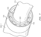
- a single/unitary inner spacer 320 may be used where the inner spacer 320 has one or more holes 720 through it to enable a passage of fluid therethrough.
- the use of the holes 720/unitary inner spacer 320 shown in FIG. 7 may represent an alternative to the use of the distance 420/multiple inner spacers 320-1 and 320-2 shown in FIG. 4D .
- the outer spacer 326 may be attached (e.g., welded) to the inner spacers 320-1 and 320-2.
- the attachment of block 500E may occur at the locations 424-1 and 424-2.
- the outer spacer 326 may be attached (e.g., welded) to the outer tube segment 308-1. The attachment of block 500F may occur at the location 426.
- the outer spacer 326 may be attached (e.g., welded) to the (next) outer tube segment 308. The attachment of block 500G may occur at the location 428.
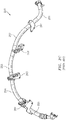
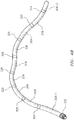
- the tube assembly is shown as a result of having substantively repeated an execution of the blocks 500D-500G for successive instances of the inner spacers 320, the outer spacers 326, and outer tube segments 308, in relation to the inner tube 314.
- the right-most outer-tube segment is denoted as segment 308-2 for purposes of further description/illustration in relation to FIGS. 4I-4J and blocks 5001-500J below.
- an inner ferrule 332 may be attached (e.g., welded) to the inner tube 314.
- an outer ferrule 338 may be attached (e.g., welded) to the outer tube segment 308-2.
- the order of the blocks/operations of the method 500 shown in FIG. 5 is illustrative. In some embodiments, one or more blocks (or one or more portions thereof) may execute in an order or sequence that is different from what is shown. One or more blocks (or one or more portions thereof) may be optional.
- a tube assembly 602 manufactured via the method 500 is shown in a mounted state relative to a portion of an engine 610 (where the engine 610 may correspond to the engine 10 of FIG. 1 ).
- the sizes/dimensions of the various components used in the manufacture of a tube assembly may be adapted to adhere to the particular application environment (e.g., engine) that the tube assembly is to be deployed on.
- a tube assembly may convey one or more fluids, such as for example oil, fuel, hydraulic fluid, air, etc.
- the fluids may be conveyed by/within one or more of the tubes of the assembly.
- a first tube may convey a first fluid and a second tube may convey a second fluid; the second fluid may be different from the first fluid.
- a component of the tube assembly may include one or more of steel, nickel, titanium, or aluminum.
- a tube assembly in accordance with aspects of this disclosure is also less complex, thereby reducing the manufacturing cost.
- a tube assembly in accordance with aspects of this disclosure is lighter than a conventional tube assembly, thereby increasing engine performance/efficiency.
Landscapes
- Engineering & Computer Science (AREA)
- General Engineering & Computer Science (AREA)
- Mechanical Engineering (AREA)
- Chemical & Material Sciences (AREA)
- Combustion & Propulsion (AREA)
- Rigid Pipes And Flexible Pipes (AREA)
Abstract
Description
- Gas turbine engines, such as those which power aircraft and industrial equipment, employ a compressor to compress air that is drawn into the engine and a turbine to capture energy associated with the combustion of a fuel-air mixture. One or more fluids are typically circulated throughout the engine. For example, oil may be supplied to one or more bearings in order to clean, cool, and lubricate the bearings.
- Referring to
FIG. 2A , the fluids are typically conveyed from a fluid source (e.g., an oil tank) 202 to the intended destination (e.g., the bearings or an associated bearing compartment) 206 by asupply tube 210. The fluid is then returned from thedestination 206 to the source 202 by areturn tube 214. In this manner, a closed-loop system 200 is established. There may be other components included; thesystem 200 is simplified for the sake of illustrative convenience. These other components may include additional tubes beyond thetubes - Referring to
FIG. 2B , in order to enhance reliability and avoid a leak impacting the performance/operability of the engine, the tubes (e.g., thetube 210 or the tube 214) may be manufactured as a double walled tube, where the fluid is intended to be conveyed by afirst tube 232. Asecond tube 236 serves to contain any fluid that may leak from thefirst tube 232. The double walled tube arrangement shown inFIG. 2B is frequently referred to as a "tube within a tube" as thetube 236 has a larger dimension/diameter than thetube 232 and thetube 232 is contained/nested within thetube 236. In this respect, thetube 232 is an inner tube relative to theouter tube 236. - Referring to
FIG. 2C , asystem 250 is shown. Thesystem 250 is shown as including five tube assemblies, denoted asassemblies assemblies FIG. 2C ; for purposes of this disclosure, this distinction is of no import and is ignored going forward). Each of the assemblies 251-255 may correspond to a double walled arrangement as shown inFIG. 2B . - As shown in
FIG. 2C , the assemblies 251-255 are separated from one another byhardware tube 232 ofFIG. 2B ) at the point where the hardware interfaces to the assemblies. - The following presents a simplified summary in order to provide a basic understanding of some aspects of the disclosure. The summary is not an extensive overview of the disclosure. It is neither intended to identify key or critical elements of the disclosure nor to delineate the scope of the disclosure. The following summary merely presents some concepts of the disclosure in a simplified form as a prelude to the description below.
- Aspects of the disclosure are directed to a tube assembly comprising: a first tube having a radial exterior surface, a second tube composed of a plurality of segments, the first tube co-axially nested within the second tube, at least a first spacer coupled to the first tube, and a second spacer coupled to the at least a first spacer, where a first segment of the plurality of segments is coupled to a first axial end of the second spacer, and a second segment of the plurality of segments is coupled to a second axial end of the second spacer. In some embodiments, the tube assembly further comprises an end fitting coupled to the first tube. In some embodiments, the second tube is coupled to the end fitting. In some embodiments, the tube assembly further comprises a first ferrule coupled to the first tube. In some embodiments, the tube assembly further comprises a second ferrule coupled to the second tube. In some embodiments, a third segment of the plurality of segments is coupled to the second ferrule. In some embodiments, the at least a first spacer includes a first inner spacer and a second inner spacer. In some embodiments, a first center of the first inner spacer is aligned with a second center of the second inner spacer relative to an axial length of the first tube. In some embodiments, the first center and the second center are separated from one another by approximately one-hundred eighty degrees relative to a circumference of the first tube. In some embodiments, a first structure of the first inner spacer is separated from a second structure of the second inner spacer by a non-zero value of distance. In some embodiments, the first tube is configured to convey a fluid. In some embodiments, the fluid includes at least one of oil, fuel, hydraulic fluid, or air. In some embodiments, the second tube is configured to convey a second fluid. In some embodiments, the tube assembly is mounted to an engine of an aircraft.
- Aspects of the disclosure are directed to a method comprising: sliding a plurality of outer tube segments onto an inner tube, using an outer spacer to separate a first and a second of the plurality of outer tube segments, attaching at least one inner spacer to the inner tube, attaching the outer spacer to the at least one inner spacer, attaching the outer spacer to the first outer tube segment, and attaching the outer spacer to the second outer tube segment. In some embodiments, the method further comprises attaching the inner tube to an end fitting. In some embodiments, the method further comprises attaching the first outer tube segment to the end fitting. In some embodiments, the method further comprises attaching an inner ferrule to the inner tube. In some embodiments, the method further comprises attaching an outer ferrule to the second outer tube segment. In some embodiments, the method further comprises attaching an outer ferrule to a third outer tube segment of the plurality of outer tube segments.
- The present disclosure is illustrated by way of example and not limited in the accompanying figures in which like reference numerals indicate similar elements. The drawings are not necessarily drawn to scale unless specifically indicated otherwise.
-
FIG. 1 is a side cutaway illustration of a geared turbine engine. -
FIG. 2A illustrates a prior art system for circulating a fluid. -
FIG. 2B illustrates a prior art double walled tube. -
FIG. 2C illustrates a prior art system incorporating tube assemblies and associated hardware. -
FIGS. 3A-3G illustrate components that may be used to manufacture a tube assembly in accordance with aspects of this disclosure. -
FIGS. 4A-4J illustrate a tube assembly at various stages of manufacture. -
FIG. 5 illustrates a flow chart of an exemplary method that may be used to manufacture a tube assembly in accordance with aspects of this disclosure. -
FIG. 6 illustrates a tube assembly mounted to an engine in accordance with aspects of this disclosure. -
FIG. 7 illustrates an inner spacer with holes defined therein to enable a passage of fluid. - It is noted that various connections are set forth between elements in the following description and in the drawings (the contents of which are included in this disclosure by way of reference). It is noted that these connections are general and, unless specified otherwise, may be direct or indirect and that this specification is not intended to be limiting in this respect. A coupling between two or more entities may refer to a direct connection or an indirect connection. An indirect connection may incorporate one or more intervening entities.
- In accordance with aspects of the disclosure, apparatuses, systems, and methods are directed to a double walled arrangement for a tube assembly. The tube assembly may include a first, inner tube surrounded by a second, outer tube. The outer tube may be composed of segments; the inner tube may be a unitary tube/piece. The tube assembly may include one or more spacers to couple the inner tube and the outer tube to one another. One or more attachment techniques, such as welding or brazing for example, may be used in the manufacture of the tube assembly.
- Aspects of the disclosure may be applied in connection with a gas turbine engine.
FIG. 1 is a side cutaway illustration of a gearedturbine engine 10. Thisturbine engine 10 extends along anaxial centerline 12 between anupstream airflow inlet 14 and adownstream airflow exhaust 16. Theturbine engine 10 includes afan section 18, acompressor section 19, acombustor section 20 and aturbine section 21. Thecompressor section 19 includes a low pressure compressor (LPC)section 19A and a high pressure compressor (HPC)section 19B. Theturbine section 21 includes a high pressure turbine (HPT)section 21A and a low pressure turbine (LPT)section 21B. - The engine sections 18-21 are arranged sequentially along the
centerline 12 within anengine housing 22. Each of the engine sections 18-19B, 21A and 21B includes a respective rotor 24-28. Each of these rotors 24-28 includes a plurality of rotor blades arranged circumferentially around and connected to one or more respective rotor disks. The rotor blades, for example, may be formed integral with or mechanically fastened, welded, brazed, adhered and/or otherwise attached to the respective rotor disk(s). - The
fan rotor 24 is connected to agear train 30, for example, through afan shaft 32. Thegear train 30 and theLPC rotor 25 are connected to and driven by theLPT rotor 28 through alow speed shaft 33. TheHPC rotor 26 is connected to and driven by theHPT rotor 27 through ahigh speed shaft 34. The shafts 32-34 are rotatably supported by a plurality ofbearings 36; e.g., rolling element and/or thrust bearings. Each of thesebearings 36 is connected to theengine housing 22 by at least one stationary structure such as, for example, an annular support strut. - During operation, air enters the
turbine engine 10 through theairflow inlet 14, and is directed through thefan section 18 and into acore gas path 38 and abypass gas path 40. The air within thecore gas path 38 may be referred to as "core air". The air within thebypass gas path 40 may be referred to as "bypass air". The core air is directed through the engine sections 19-21, and exits theturbine engine 10 through theairflow exhaust 16 to provide forward engine thrust. Within thecombustor section 20, fuel is injected into acombustion chamber 42 and mixed with compressed core air. This fuel-core air mixture is ignited to power theturbine engine 10. The bypass air is directed through thebypass gas path 40 and out of theturbine engine 10 through abypass nozzle 44 to provide additional forward engine thrust. This additional forward engine thrust may account for a majority (e.g., more than 70 percent) of total engine thrust. Alternatively, at least some of the bypass air may be directed out of theturbine engine 10 through a thrust reverser to provide reverse engine thrust. -
FIG. 1 represents one possible configuration for anengine 10. Aspects of the disclosure may be applied in connection with other environments, including additional configurations for gas turbine engines. Aspects of the disclosure may be applied in connection with non-geared engines. - Referring to
FIGS. 3A-3G , various components used in the manufacture of a tube assembly are shown. In particular,FIGS. 3A-3G illustrate an end fitting 302, anouter tube segment 308, aninner tube 314, a portion of a first (inner) spacer 320, a second (outer) spacer 326, a first (inner) ferrule 332, and a second (outer) ferrule 338, respectively. -
FIG. 4A-4J illustrate a tube assembly at various stages of manufacture, where the tube assembly is manufactured using the components depicted inFIGS. 3A-3G . The manufacture of the tube assembly is further described in relation to themethod 500 ofFIG. 5 . - In
block 500A (corresponding toFIG. 4A ), outer tube segments 308-1 and 308 may be slid onto/on top of aninner tube 314.Outer spacers 326 may be used to separate the segments 308-1 and 308 from one another. - In
block 500B (corresponding toFIG. 4B ), theinner tube 314 may be attached (e.g., welded) to anend fitting 302. - In
block 500C (corresponding toFIG. 4C ), the outer tube segment 308-1 may be attached (e.g., welded) to the end fitting 302. - In
block 500D (corresponding toFIG. 4D ), two inner spacers 320-1 and 320-2 may be attached (e.g., welded) to theinner tube 314. The respective centers of the spacers 320-1 and 320-2 may be substantially aligned with one another relative to an axial length of theinner tube 314 and separated from one another by approximately one-hundred eighty degrees relative to a circumference of theinner tube 314. The structures of the spacers 320-1 and 320-2 may be separated from one another by adistance 420. Any non-zero value of thedistance 420 may allow any fluid that escapes from/leaks out of theinner tube 314 to traverse the region between theinner pipe 314 and the outer pipe (or theouter pipe segments 308, 308-1, 308-2 : see alsoFIG. 4H ). Stated slightly differently, providing for a non-zero value of thedistance 420 may help to prevent a build-up of any leaking fluid at the spacers 320-1 and 320-2 by providing a path for that leaked fluid to flow. - Referring to
FIG. 7 , in some embodiments a single/unitaryinner spacer 320 may be used where theinner spacer 320 has one ormore holes 720 through it to enable a passage of fluid therethrough. The use of theholes 720/unitaryinner spacer 320 shown inFIG. 7 may represent an alternative to the use of thedistance 420/multiple inner spacers 320-1 and 320-2 shown inFIG. 4D . - Referring back to
FIG. 5 , inblock 500E (corresponding toFIG. 4E ), theouter spacer 326 may be attached (e.g., welded) to the inner spacers 320-1 and 320-2. The attachment ofblock 500E may occur at the locations 424-1 and 424-2. - In
block 500F (corresponding toFIG. 4F ), theouter spacer 326 may be attached (e.g., welded) to the outer tube segment 308-1. The attachment ofblock 500F may occur at thelocation 426. - In
block 500G (corresponding toFIG. 4G ), theouter spacer 326 may be attached (e.g., welded) to the (next)outer tube segment 308. The attachment ofblock 500G may occur at thelocation 428. - Referring to
FIG. 4H , the tube assembly is shown as a result of having substantively repeated an execution of theblocks 500D-500G for successive instances of theinner spacers 320, theouter spacers 326, andouter tube segments 308, in relation to theinner tube 314. InFIG. 4H , the right-most outer-tube segment is denoted as segment 308-2 for purposes of further description/illustration in relation toFIGS. 4I-4J and blocks 5001-500J below. - In block 500I (corresponding to
FIG. 4I ), aninner ferrule 332 may be attached (e.g., welded) to theinner tube 314. - In
block 500J (corresponding toFIG. 4J ), anouter ferrule 338 may be attached (e.g., welded) to the outer tube segment 308-2. - The order of the blocks/operations of the
method 500 shown inFIG. 5 is illustrative. In some embodiments, one or more blocks (or one or more portions thereof) may execute in an order or sequence that is different from what is shown. One or more blocks (or one or more portions thereof) may be optional. - Referring to
FIGS. 5-6 , atube assembly 602 manufactured via themethod 500 is shown in a mounted state relative to a portion of an engine 610 (where theengine 610 may correspond to theengine 10 ofFIG. 1 ). - The sizes/dimensions of the various components used in the manufacture of a tube assembly may be adapted to adhere to the particular application environment (e.g., engine) that the tube assembly is to be deployed on.
- A tube assembly may convey one or more fluids, such as for example oil, fuel, hydraulic fluid, air, etc. The fluids may be conveyed by/within one or more of the tubes of the assembly. For example, in some embodiments a first tube may convey a first fluid and a second tube may convey a second fluid; the second fluid may be different from the first fluid.
- One or more materials may be used in the manufacture of a tube assembly. For example, a component of the tube assembly may include one or more of steel, nickel, titanium, or aluminum.
- Technical effects and benefits of this disclosure include a tube assembly that is less susceptible to leaking fluid relative to conventional tube assemblies. A tube assembly in accordance with aspects of this disclosure is also less complex, thereby reducing the manufacturing cost. A tube assembly in accordance with aspects of this disclosure is lighter than a conventional tube assembly, thereby increasing engine performance/efficiency.
- Aspects of the disclosure have been described in terms of illustrative embodiments thereof. Numerous other embodiments, modifications, and variations within the scope of the appended claims will occur to persons of ordinary skill in the art from a review of this disclosure. For example, one of ordinary skill in the art will appreciate that the steps described in conjunction with the illustrative figures may be performed in other than the recited order, and that one or more steps illustrated may be optional in accordance with aspects of the disclosure. One or more features described in connection with a first embodiment may be combined with one or more features of one or more additional embodiments.
Claims (15)
- A tube assembly comprising:a first tube (314) having a radial exterior surface;a second tube composed of a plurality of segments (308, 308-1, 308-2), the first tube (314) co-axially nested within the second tube;at least a first spacer (320-1, 320-2) coupled to the first tube (314); anda second spacer (326) coupled to the at least a first spacer (320-1, 320-2),wherein a first segment (308-1) of the plurality of segments (308, 308-1, 308-2) is coupled to a first axial end of the second spacer (326), andwherein a second segment (308) of the plurality of segments (308, 308-1, 308-2) is coupled to a second axial end of the second spacer (326).
- The tube assembly of claim 1, further comprising:an end fitting (302) coupled to the first tube (314).
- The tube assembly of claim 2, wherein the second tube is coupled to the end fitting (302).
- The tube assembly of any preceding claim, further comprising:a first ferrule (332) coupled to the first tube (314).
- The tube assembly of claim 4, further comprising:a second ferrule (338) coupled to the second tube;wherein optionally a third segment (308-2) of the plurality of segments (308, 308-1, 308-2) is coupled to the second ferrule (338).
- The tube assembly of any preceding claim, wherein the at least a first spacer (320-1, 320-2) includes a first inner spacer (320-1) and a second inner spacer (320-2).
- The tube assembly of claim 6, wherein a first center of the first inner spacer (320-1) is aligned with a second center of the second inner spacer (320-2) relative to an axial length of the first tube (314);
wherein optionally the first center and the second center are separated from one another by approximately one-hundred eighty degrees relative to a circumference of the first tube (314). - The tube assembly of claim 6 or 7, wherein a first structure of the first inner spacer (320-1) is separated from a second structure of the second inner spacer (320-2) by a non-zero value of distance (420).
- The tube assembly of any preceding claim, wherein the first tube (314) is configured to convey a fluid.
- The tube assembly of claim 9, wherein:the fluid includes at least one of oil, fuel, hydraulic fluid, or air; and/orthe second tube is configured to convey a second fluid.
- The tube assembly of any preceding claim, wherein the tube assembly is mounted to an engine (10) of an aircraft.
- A method comprising:sliding a plurality of outer tube segments (308, 308-1, 308-2) onto an inner tube (314);using an outer spacer (326) to separate a first (308-1) and a second (308) of the plurality of outer tube segments (308, 308-1, 308-2);attaching at least one inner spacer (320-1, 320-2) to the inner tube (314);attaching the outer spacer (326) to the at least one inner spacer (320-1, 320-2);attaching the outer spacer (326) to the first outer tube segment (308-1); andattaching the outer spacer (326) to the second outer tube segment (308).
- The method of claim 12, further comprising:attaching the inner tube (314) to an end fitting (302), wherein the method optionally further comprises:attaching the first outer tube segment (308-1) to the end fitting (302).
- The method of claim 12 or 13, further comprising:attaching an inner ferrule (332) to the inner tube (314).
- The method of claim 14, further comprising:attaching an outer ferrule (338) to the second outer tube segment (308); and/orattaching an outer ferrule (338) to a third outer tube segment (308-2) of the plurality of outer tube segments (308, 308-1, 308-2).
Applications Claiming Priority (1)
| Application Number | Priority Date | Filing Date | Title |
|---|---|---|---|
| US15/174,311 US10006568B2 (en) | 2016-06-06 | 2016-06-06 | Double walled tube and manufacture thereof |
Publications (2)
| Publication Number | Publication Date |
|---|---|
| EP3255326A1 true EP3255326A1 (en) | 2017-12-13 |
| EP3255326B1 EP3255326B1 (en) | 2020-08-12 |
Family
ID=59034479
Family Applications (1)
| Application Number | Title | Priority Date | Filing Date |
|---|---|---|---|
| EP17174631.6A Active EP3255326B1 (en) | 2016-06-06 | 2017-06-06 | Double walled tube and manufacture thereof |
Country Status (2)
| Country | Link |
|---|---|
| US (1) | US10006568B2 (en) |
| EP (1) | EP3255326B1 (en) |
Cited By (1)
| Publication number | Priority date | Publication date | Assignee | Title |
|---|---|---|---|---|
| EP3527489A1 (en) * | 2018-02-20 | 2019-08-21 | Airbus Operations, S.L.U. | Hydraulic system for an aircraft |
Families Citing this family (7)
| Publication number | Priority date | Publication date | Assignee | Title |
|---|---|---|---|---|
| EP3246609B1 (en) | 2016-05-20 | 2020-09-09 | Airbus Operations GmbH | Shrouded pipe |
| EP3246610B1 (en) * | 2016-05-20 | 2019-07-03 | Airbus Operations GmbH | Shrouded pipe |
| US20180142809A1 (en) * | 2016-11-23 | 2018-05-24 | General Electric Company | Systems and methods for ensuring the correct orientation of tubing in a gas turbine engine |
| US10393303B2 (en) * | 2017-02-06 | 2019-08-27 | United Technologies Corporation | Threaded fitting for tube |
| US11378214B2 (en) * | 2020-06-26 | 2022-07-05 | Lawrence Wolf | Coaxial tubing systems with securable spacers |
| EP4249380B1 (en) | 2022-03-21 | 2025-07-30 | Zero Emissions Aerospace Limited | Fuel line safety protection system |
| US12601299B1 (en) * | 2025-04-16 | 2026-04-14 | General Electric Company | Hydrogen fuel system for an aircraft |
Citations (3)
| Publication number | Priority date | Publication date | Assignee | Title |
|---|---|---|---|---|
| US20040026922A1 (en) * | 2002-08-09 | 2004-02-12 | Carns James A. | Shrouded fluid-conducting apparatus |
| EP2578916A1 (en) * | 2011-10-07 | 2013-04-10 | Dassault Aviation | Double-walled pipe for transporting a fluid, installation of such a pipe and aircraft comprising such a pipe |
| EP2957804A1 (en) * | 2014-06-18 | 2015-12-23 | United Technologies Corporation | Double wall tube assemblies |
Family Cites Families (14)
| Publication number | Priority date | Publication date | Assignee | Title |
|---|---|---|---|---|
| US2737543A (en) | 1951-06-02 | 1956-03-06 | Gen Motors Corp | Wiring harness for aircraft engines |
| US3343250A (en) | 1964-04-22 | 1967-09-26 | Douglas Aircraft Co Inc | Multiple tube forming method |
| US4250927A (en) | 1979-08-24 | 1981-02-17 | Piper Aircraft Corporation | Duct spacer clip and duct assembly |
| US4645244A (en) | 1984-02-15 | 1987-02-24 | Edwin Curtis | Aircraft duct gimbaled joint |
| US5028078A (en) | 1990-02-05 | 1991-07-02 | The Pullman Company | Tube fitting with variable tube insertion |
| US5225016A (en) | 1991-08-02 | 1993-07-06 | Rohr Industries, Inc. | Method of manufacturing an advanced composite duct having integral ribs |
| FR2699644B1 (en) | 1992-12-23 | 1995-01-20 | Snecma | Elastic ring with stress indicator for fitting. |
| US5497809A (en) * | 1994-01-05 | 1996-03-12 | Wolf; Lawrence W. | Vented bending sleeves for coaxial tubing systems |
| FR2746891B1 (en) | 1996-03-29 | 1998-06-05 | Itp | PIPE FOR DUAL THERMAL INSULATING PIPE TYPE PIPES |
| US6487860B2 (en) | 2000-12-08 | 2002-12-03 | General Electric Company | Turbine engine fuel supply system |
| US6786275B2 (en) | 2002-05-23 | 2004-09-07 | Valeo Engine Cooling | Heat exchanger header assembly |
| US7913718B1 (en) * | 2008-01-10 | 2011-03-29 | Cornwall Kenneth R | Noise reduction system |
| US7992390B2 (en) | 2008-09-23 | 2011-08-09 | Pratt & Whitney Canada Corp. | External rigid fuel manifold |
| US10161635B2 (en) | 2014-06-13 | 2018-12-25 | Rolls-Royce Corporation | Combustor with spring-loaded crossover tubes |
-
2016
- 2016-06-06 US US15/174,311 patent/US10006568B2/en active Active
-
2017
- 2017-06-06 EP EP17174631.6A patent/EP3255326B1/en active Active
Patent Citations (3)
| Publication number | Priority date | Publication date | Assignee | Title |
|---|---|---|---|---|
| US20040026922A1 (en) * | 2002-08-09 | 2004-02-12 | Carns James A. | Shrouded fluid-conducting apparatus |
| EP2578916A1 (en) * | 2011-10-07 | 2013-04-10 | Dassault Aviation | Double-walled pipe for transporting a fluid, installation of such a pipe and aircraft comprising such a pipe |
| EP2957804A1 (en) * | 2014-06-18 | 2015-12-23 | United Technologies Corporation | Double wall tube assemblies |
Cited By (1)
| Publication number | Priority date | Publication date | Assignee | Title |
|---|---|---|---|---|
| EP3527489A1 (en) * | 2018-02-20 | 2019-08-21 | Airbus Operations, S.L.U. | Hydraulic system for an aircraft |
Also Published As
| Publication number | Publication date |
|---|---|
| US20170350540A1 (en) | 2017-12-07 |
| EP3255326B1 (en) | 2020-08-12 |
| US10006568B2 (en) | 2018-06-26 |
Similar Documents
| Publication | Publication Date | Title |
|---|---|---|
| EP3255326B1 (en) | Double walled tube and manufacture thereof | |
| US10443436B2 (en) | Modular annular heat exchanger | |
| CA2872038C (en) | High durability turbine exhaust case | |
| EP3358139B1 (en) | Threaded fitting for tube | |
| EP3093467B1 (en) | Lubrication system for geared gas turbine engine | |
| EP3358140B1 (en) | Fitting for multiwall tube | |
| EP3358141A1 (en) | Multiwall tube and fitting for bearing oil supply | |
| US11391326B2 (en) | Flexible coupling shaft for turbine engine | |
| US11591969B2 (en) | Method and system of connecting a turbine engine gearbox to engine core | |
| US9896969B2 (en) | Zero or low leakage oil transfer bearing | |
| US20170184124A1 (en) | Turbofan engine assembly and methods of assembling the same | |
| EP3447249B1 (en) | Sealing configurations with active cooling features | |
| EP3296053B1 (en) | Triple-weld fitting | |
| EP3081748B1 (en) | Gas turbine engine system comprising a seal ring | |
| US11578829B2 (en) | Middle threaded fitting | |
| US10036503B2 (en) | Shim to maintain gap during engine assembly | |
| US10815830B2 (en) | Lightweight tierod |
Legal Events
| Date | Code | Title | Description |
|---|---|---|---|
| PUAI | Public reference made under article 153(3) epc to a published international application that has entered the european phase |
Free format text: ORIGINAL CODE: 0009012 |
|
| STAA | Information on the status of an ep patent application or granted ep patent |
Free format text: STATUS: THE APPLICATION HAS BEEN PUBLISHED |
|
| AK | Designated contracting states |
Kind code of ref document: A1 Designated state(s): AL AT BE BG CH CY CZ DE DK EE ES FI FR GB GR HR HU IE IS IT LI LT LU LV MC MK MT NL NO PL PT RO RS SE SI SK SM TR |
|
| AX | Request for extension of the european patent |
Extension state: BA ME |
|
| STAA | Information on the status of an ep patent application or granted ep patent |
Free format text: STATUS: REQUEST FOR EXAMINATION WAS MADE |
|
| 17P | Request for examination filed |
Effective date: 20180613 |
|
| RBV | Designated contracting states (corrected) |
Designated state(s): AL AT BE BG CH CY CZ DE DK EE ES FI FR GB GR HR HU IE IS IT LI LT LU LV MC MK MT NL NO PL PT RO RS SE SI SK SM TR |
|
| GRAP | Despatch of communication of intention to grant a patent |
Free format text: ORIGINAL CODE: EPIDOSNIGR1 |
|
| STAA | Information on the status of an ep patent application or granted ep patent |
Free format text: STATUS: GRANT OF PATENT IS INTENDED |
|
| RIC1 | Information provided on ipc code assigned before grant |
Ipc: F16L 39/00 20060101ALI20200129BHEP Ipc: F16L 9/18 20060101AFI20200129BHEP Ipc: F01D 25/18 20060101ALI20200129BHEP Ipc: G01M 3/00 20060101ALI20200129BHEP Ipc: F01D 25/00 20060101ALI20200129BHEP Ipc: F02C 7/22 20060101ALI20200129BHEP Ipc: F02C 7/00 20060101ALI20200129BHEP Ipc: F02C 7/32 20060101ALI20200129BHEP |
|
| INTG | Intention to grant announced |
Effective date: 20200228 |
|
| RIN1 | Information on inventor provided before grant (corrected) |
Inventor name: SCHEIFERSTEIN, GREGORY S. Inventor name: CALLAGHAN, CRAIG M. |
|
| GRAS | Grant fee paid |
Free format text: ORIGINAL CODE: EPIDOSNIGR3 |
|
| GRAA | (expected) grant |
Free format text: ORIGINAL CODE: 0009210 |
|
| STAA | Information on the status of an ep patent application or granted ep patent |
Free format text: STATUS: THE PATENT HAS BEEN GRANTED |
|
| AK | Designated contracting states |
Kind code of ref document: B1 Designated state(s): AL AT BE BG CH CY CZ DE DK EE ES FI FR GB GR HR HU IE IS IT LI LT LU LV MC MK MT NL NO PL PT RO RS SE SI SK SM TR |
|
| REG | Reference to a national code |
Ref country code: CH Ref legal event code: EP |
|
| REG | Reference to a national code |
Ref country code: IE Ref legal event code: FG4D |
|
| REG | Reference to a national code |
Ref country code: DE Ref legal event code: R096 Ref document number: 602017021427 Country of ref document: DE |
|
| REG | Reference to a national code |
Ref country code: AT Ref legal event code: REF Ref document number: 1301875 Country of ref document: AT Kind code of ref document: T Effective date: 20200915 |
|
| REG | Reference to a national code |
Ref country code: LT Ref legal event code: MG4D |
|
| REG | Reference to a national code |
Ref country code: NL Ref legal event code: MP Effective date: 20200812 |
|
| PG25 | Lapsed in a contracting state [announced via postgrant information from national office to epo] |
Ref country code: FI Free format text: LAPSE BECAUSE OF FAILURE TO SUBMIT A TRANSLATION OF THE DESCRIPTION OR TO PAY THE FEE WITHIN THE PRESCRIBED TIME-LIMIT Effective date: 20200812 Ref country code: SE Free format text: LAPSE BECAUSE OF FAILURE TO SUBMIT A TRANSLATION OF THE DESCRIPTION OR TO PAY THE FEE WITHIN THE PRESCRIBED TIME-LIMIT Effective date: 20200812 Ref country code: BG Free format text: LAPSE BECAUSE OF FAILURE TO SUBMIT A TRANSLATION OF THE DESCRIPTION OR TO PAY THE FEE WITHIN THE PRESCRIBED TIME-LIMIT Effective date: 20201112 Ref country code: GR Free format text: LAPSE BECAUSE OF FAILURE TO SUBMIT A TRANSLATION OF THE DESCRIPTION OR TO PAY THE FEE WITHIN THE PRESCRIBED TIME-LIMIT Effective date: 20201113 Ref country code: NO Free format text: LAPSE BECAUSE OF FAILURE TO SUBMIT A TRANSLATION OF THE DESCRIPTION OR TO PAY THE FEE WITHIN THE PRESCRIBED TIME-LIMIT Effective date: 20201112 Ref country code: HR Free format text: LAPSE BECAUSE OF FAILURE TO SUBMIT A TRANSLATION OF THE DESCRIPTION OR TO PAY THE FEE WITHIN THE PRESCRIBED TIME-LIMIT Effective date: 20200812 Ref country code: LT Free format text: LAPSE BECAUSE OF FAILURE TO SUBMIT A TRANSLATION OF THE DESCRIPTION OR TO PAY THE FEE WITHIN THE PRESCRIBED TIME-LIMIT Effective date: 20200812 |
|
| REG | Reference to a national code |
Ref country code: AT Ref legal event code: MK05 Ref document number: 1301875 Country of ref document: AT Kind code of ref document: T Effective date: 20200812 |
|
| PG25 | Lapsed in a contracting state [announced via postgrant information from national office to epo] |
Ref country code: PL Free format text: LAPSE BECAUSE OF FAILURE TO SUBMIT A TRANSLATION OF THE DESCRIPTION OR TO PAY THE FEE WITHIN THE PRESCRIBED TIME-LIMIT Effective date: 20200812 Ref country code: NL Free format text: LAPSE BECAUSE OF FAILURE TO SUBMIT A TRANSLATION OF THE DESCRIPTION OR TO PAY THE FEE WITHIN THE PRESCRIBED TIME-LIMIT Effective date: 20200812 Ref country code: LV Free format text: LAPSE BECAUSE OF FAILURE TO SUBMIT A TRANSLATION OF THE DESCRIPTION OR TO PAY THE FEE WITHIN THE PRESCRIBED TIME-LIMIT Effective date: 20200812 Ref country code: RS Free format text: LAPSE BECAUSE OF FAILURE TO SUBMIT A TRANSLATION OF THE DESCRIPTION OR TO PAY THE FEE WITHIN THE PRESCRIBED TIME-LIMIT Effective date: 20200812 Ref country code: IS Free format text: LAPSE BECAUSE OF FAILURE TO SUBMIT A TRANSLATION OF THE DESCRIPTION OR TO PAY THE FEE WITHIN THE PRESCRIBED TIME-LIMIT Effective date: 20201212 |
|
| RAP2 | Party data changed (patent owner data changed or rights of a patent transferred) |
Owner name: RAYTHEON TECHNOLOGIES CORPORATION |
|
| PG25 | Lapsed in a contracting state [announced via postgrant information from national office to epo] |
Ref country code: EE Free format text: LAPSE BECAUSE OF FAILURE TO SUBMIT A TRANSLATION OF THE DESCRIPTION OR TO PAY THE FEE WITHIN THE PRESCRIBED TIME-LIMIT Effective date: 20200812 Ref country code: SM Free format text: LAPSE BECAUSE OF FAILURE TO SUBMIT A TRANSLATION OF THE DESCRIPTION OR TO PAY THE FEE WITHIN THE PRESCRIBED TIME-LIMIT Effective date: 20200812 Ref country code: CZ Free format text: LAPSE BECAUSE OF FAILURE TO SUBMIT A TRANSLATION OF THE DESCRIPTION OR TO PAY THE FEE WITHIN THE PRESCRIBED TIME-LIMIT Effective date: 20200812 Ref country code: DK Free format text: LAPSE BECAUSE OF FAILURE TO SUBMIT A TRANSLATION OF THE DESCRIPTION OR TO PAY THE FEE WITHIN THE PRESCRIBED TIME-LIMIT Effective date: 20200812 Ref country code: RO Free format text: LAPSE BECAUSE OF FAILURE TO SUBMIT A TRANSLATION OF THE DESCRIPTION OR TO PAY THE FEE WITHIN THE PRESCRIBED TIME-LIMIT Effective date: 20200812 |
|
| REG | Reference to a national code |
Ref country code: DE Ref legal event code: R097 Ref document number: 602017021427 Country of ref document: DE |
|
| PG25 | Lapsed in a contracting state [announced via postgrant information from national office to epo] |
Ref country code: ES Free format text: LAPSE BECAUSE OF FAILURE TO SUBMIT A TRANSLATION OF THE DESCRIPTION OR TO PAY THE FEE WITHIN THE PRESCRIBED TIME-LIMIT Effective date: 20200812 Ref country code: AL Free format text: LAPSE BECAUSE OF FAILURE TO SUBMIT A TRANSLATION OF THE DESCRIPTION OR TO PAY THE FEE WITHIN THE PRESCRIBED TIME-LIMIT Effective date: 20200812 Ref country code: AT Free format text: LAPSE BECAUSE OF FAILURE TO SUBMIT A TRANSLATION OF THE DESCRIPTION OR TO PAY THE FEE WITHIN THE PRESCRIBED TIME-LIMIT Effective date: 20200812 |
|
| PLBE | No opposition filed within time limit |
Free format text: ORIGINAL CODE: 0009261 |
|
| STAA | Information on the status of an ep patent application or granted ep patent |
Free format text: STATUS: NO OPPOSITION FILED WITHIN TIME LIMIT |
|
| PG25 | Lapsed in a contracting state [announced via postgrant information from national office to epo] |
Ref country code: SK Free format text: LAPSE BECAUSE OF FAILURE TO SUBMIT A TRANSLATION OF THE DESCRIPTION OR TO PAY THE FEE WITHIN THE PRESCRIBED TIME-LIMIT Effective date: 20200812 |
|
| 26N | No opposition filed |
Effective date: 20210514 |
|
| PG25 | Lapsed in a contracting state [announced via postgrant information from national office to epo] |
Ref country code: IT Free format text: LAPSE BECAUSE OF FAILURE TO SUBMIT A TRANSLATION OF THE DESCRIPTION OR TO PAY THE FEE WITHIN THE PRESCRIBED TIME-LIMIT Effective date: 20200812 |
|
| PG25 | Lapsed in a contracting state [announced via postgrant information from national office to epo] |
Ref country code: SI Free format text: LAPSE BECAUSE OF FAILURE TO SUBMIT A TRANSLATION OF THE DESCRIPTION OR TO PAY THE FEE WITHIN THE PRESCRIBED TIME-LIMIT Effective date: 20200812 |
|
| PG25 | Lapsed in a contracting state [announced via postgrant information from national office to epo] |
Ref country code: MC Free format text: LAPSE BECAUSE OF FAILURE TO SUBMIT A TRANSLATION OF THE DESCRIPTION OR TO PAY THE FEE WITHIN THE PRESCRIBED TIME-LIMIT Effective date: 20200812 |
|
| REG | Reference to a national code |
Ref country code: CH Ref legal event code: PL |
|
| REG | Reference to a national code |
Ref country code: BE Ref legal event code: MM Effective date: 20210630 |
|
| PG25 | Lapsed in a contracting state [announced via postgrant information from national office to epo] |
Ref country code: LU Free format text: LAPSE BECAUSE OF NON-PAYMENT OF DUE FEES Effective date: 20210606 |
|
| PG25 | Lapsed in a contracting state [announced via postgrant information from national office to epo] |
Ref country code: LI Free format text: LAPSE BECAUSE OF NON-PAYMENT OF DUE FEES Effective date: 20210630 Ref country code: IE Free format text: LAPSE BECAUSE OF NON-PAYMENT OF DUE FEES Effective date: 20210606 Ref country code: CH Free format text: LAPSE BECAUSE OF NON-PAYMENT OF DUE FEES Effective date: 20210630 |
|
| PG25 | Lapsed in a contracting state [announced via postgrant information from national office to epo] |
Ref country code: BE Free format text: LAPSE BECAUSE OF NON-PAYMENT OF DUE FEES Effective date: 20210630 |
|
| PG25 | Lapsed in a contracting state [announced via postgrant information from national office to epo] |
Ref country code: PT Free format text: LAPSE BECAUSE OF FAILURE TO SUBMIT A TRANSLATION OF THE DESCRIPTION OR TO PAY THE FEE WITHIN THE PRESCRIBED TIME-LIMIT Effective date: 20201214 |
|
| PG25 | Lapsed in a contracting state [announced via postgrant information from national office to epo] |
Ref country code: HU Free format text: LAPSE BECAUSE OF FAILURE TO SUBMIT A TRANSLATION OF THE DESCRIPTION OR TO PAY THE FEE WITHIN THE PRESCRIBED TIME-LIMIT; INVALID AB INITIO Effective date: 20170606 |
|
| P01 | Opt-out of the competence of the unified patent court (upc) registered |
Effective date: 20230520 |
|
| PG25 | Lapsed in a contracting state [announced via postgrant information from national office to epo] |
Ref country code: CY Free format text: LAPSE BECAUSE OF FAILURE TO SUBMIT A TRANSLATION OF THE DESCRIPTION OR TO PAY THE FEE WITHIN THE PRESCRIBED TIME-LIMIT Effective date: 20200812 |
|
| PG25 | Lapsed in a contracting state [announced via postgrant information from national office to epo] |
Ref country code: MK Free format text: LAPSE BECAUSE OF FAILURE TO SUBMIT A TRANSLATION OF THE DESCRIPTION OR TO PAY THE FEE WITHIN THE PRESCRIBED TIME-LIMIT Effective date: 20200812 |
|
| PG25 | Lapsed in a contracting state [announced via postgrant information from national office to epo] |
Ref country code: MT Free format text: LAPSE BECAUSE OF FAILURE TO SUBMIT A TRANSLATION OF THE DESCRIPTION OR TO PAY THE FEE WITHIN THE PRESCRIBED TIME-LIMIT Effective date: 20200812 |
|
| PGFP | Annual fee paid to national office [announced via postgrant information from national office to epo] |
Ref country code: DE Payment date: 20250520 Year of fee payment: 9 |
|
| PGFP | Annual fee paid to national office [announced via postgrant information from national office to epo] |
Ref country code: GB Payment date: 20250520 Year of fee payment: 9 |
|
| PGFP | Annual fee paid to national office [announced via postgrant information from national office to epo] |
Ref country code: FR Payment date: 20250520 Year of fee payment: 9 |
|
| REG | Reference to a national code |
Ref country code: DE Ref legal event code: R081 Ref document number: 602017021427 Country of ref document: DE Owner name: RTX CORPORATION (N.D.GES.D. STAATES DELAWARE),, US Free format text: FORMER OWNER: UNITED TECHNOLOGIES CORPORATION, FARMINGTON, CONN., US |
|
| PG25 | Lapsed in a contracting state [announced via postgrant information from national office to epo] |
Ref country code: TR Free format text: LAPSE BECAUSE OF FAILURE TO SUBMIT A TRANSLATION OF THE DESCRIPTION OR TO PAY THE FEE WITHIN THE PRESCRIBED TIME-LIMIT Effective date: 20200812 |