EP3255308A1 - Ball screw mechanism and steering system - Google Patents
Ball screw mechanism and steering system Download PDFInfo
- Publication number
- EP3255308A1 EP3255308A1 EP17171498.3A EP17171498A EP3255308A1 EP 3255308 A1 EP3255308 A1 EP 3255308A1 EP 17171498 A EP17171498 A EP 17171498A EP 3255308 A1 EP3255308 A1 EP 3255308A1
- Authority
- EP
- European Patent Office
- Prior art keywords
- nut
- retainer
- enlarged diameter
- diameter portion
- groove
- Prior art date
- Legal status (The legal status is an assumption and is not a legal conclusion. Google has not performed a legal analysis and makes no representation as to the accuracy of the status listed.)
- Granted
Links
- 230000007246 mechanism Effects 0.000 title claims abstract description 58
- 230000009467 reduction Effects 0.000 abstract description 15
- 230000000717 retained effect Effects 0.000 abstract description 3
- 238000005096 rolling process Methods 0.000 description 8
- 238000013459 approach Methods 0.000 description 7
- 238000010586 diagram Methods 0.000 description 5
- 230000000694 effects Effects 0.000 description 5
- 229910000831 Steel Inorganic materials 0.000 description 3
- 230000004323 axial length Effects 0.000 description 3
- 239000010959 steel Substances 0.000 description 3
- 229910000640 Fe alloy Inorganic materials 0.000 description 2
- 239000011347 resin Substances 0.000 description 2
- 229920005989 resin Polymers 0.000 description 2
- 230000008859 change Effects 0.000 description 1
- 239000002131 composite material Substances 0.000 description 1
- 230000007423 decrease Effects 0.000 description 1
- 230000005484 gravity Effects 0.000 description 1
- 239000004519 grease Substances 0.000 description 1
- 239000000314 lubricant Substances 0.000 description 1
- 238000003754 machining Methods 0.000 description 1
- 229910052751 metal Inorganic materials 0.000 description 1
- 239000007769 metal material Substances 0.000 description 1
- 230000004048 modification Effects 0.000 description 1
- 238000012986 modification Methods 0.000 description 1
Images


Classifications
-
- B—PERFORMING OPERATIONS; TRANSPORTING
- B62—LAND VEHICLES FOR TRAVELLING OTHERWISE THAN ON RAILS
- B62D—MOTOR VEHICLES; TRAILERS
- B62D5/00—Power-assisted or power-driven steering
- B62D5/04—Power-assisted or power-driven steering electrical, e.g. using an electric servo-motor connected to, or forming part of, the steering gear
- B62D5/0442—Conversion of rotational into longitudinal movement
- B62D5/0445—Screw drives
- B62D5/0448—Ball nuts
-
- F—MECHANICAL ENGINEERING; LIGHTING; HEATING; WEAPONS; BLASTING
- F16—ENGINEERING ELEMENTS AND UNITS; GENERAL MEASURES FOR PRODUCING AND MAINTAINING EFFECTIVE FUNCTIONING OF MACHINES OR INSTALLATIONS; THERMAL INSULATION IN GENERAL
- F16H—GEARING
- F16H25/00—Gearings comprising primarily only cams, cam-followers and screw-and-nut mechanisms
- F16H25/18—Gearings comprising primarily only cams, cam-followers and screw-and-nut mechanisms for conveying or interconverting oscillating or reciprocating motions
- F16H25/20—Screw mechanisms
- F16H25/22—Screw mechanisms with balls, rollers, or similar members between the co-operating parts; Elements essential to the use of such members
-
- B—PERFORMING OPERATIONS; TRANSPORTING
- B62—LAND VEHICLES FOR TRAVELLING OTHERWISE THAN ON RAILS
- B62D—MOTOR VEHICLES; TRAILERS
- B62D5/00—Power-assisted or power-driven steering
- B62D5/04—Power-assisted or power-driven steering electrical, e.g. using an electric servo-motor connected to, or forming part of, the steering gear
- B62D5/0421—Electric motor acting on or near steering gear
- B62D5/0424—Electric motor acting on or near steering gear the axes of motor and final driven element of steering gear, e.g. rack, being parallel
-
- F—MECHANICAL ENGINEERING; LIGHTING; HEATING; WEAPONS; BLASTING
- F16—ENGINEERING ELEMENTS AND UNITS; GENERAL MEASURES FOR PRODUCING AND MAINTAINING EFFECTIVE FUNCTIONING OF MACHINES OR INSTALLATIONS; THERMAL INSULATION IN GENERAL
- F16H—GEARING
- F16H25/00—Gearings comprising primarily only cams, cam-followers and screw-and-nut mechanisms
- F16H25/18—Gearings comprising primarily only cams, cam-followers and screw-and-nut mechanisms for conveying or interconverting oscillating or reciprocating motions
- F16H25/20—Screw mechanisms
- F16H25/22—Screw mechanisms with balls, rollers, or similar members between the co-operating parts; Elements essential to the use of such members
- F16H25/2204—Screw mechanisms with balls, rollers, or similar members between the co-operating parts; Elements essential to the use of such members with balls
- F16H25/2233—Screw mechanisms with balls, rollers, or similar members between the co-operating parts; Elements essential to the use of such members with balls with cages or means to hold the balls in position
-
- F—MECHANICAL ENGINEERING; LIGHTING; HEATING; WEAPONS; BLASTING
- F16—ENGINEERING ELEMENTS AND UNITS; GENERAL MEASURES FOR PRODUCING AND MAINTAINING EFFECTIVE FUNCTIONING OF MACHINES OR INSTALLATIONS; THERMAL INSULATION IN GENERAL
- F16H—GEARING
- F16H25/00—Gearings comprising primarily only cams, cam-followers and screw-and-nut mechanisms
- F16H25/18—Gearings comprising primarily only cams, cam-followers and screw-and-nut mechanisms for conveying or interconverting oscillating or reciprocating motions
- F16H25/20—Screw mechanisms
- F16H25/24—Elements essential to such mechanisms, e.g. screws, nuts
Definitions
- the invention relates to a ball screw mechanism and a steering system.
- Some ball screw mechanisms include a screw shaft with a helical screw groove on the outer circumferential surface and a nut with a helical screw groove corresponding to the screw groove of the screw shaft.
- This type of ball screw mechanism is used in steering systems that steer steered wheels by converting rotary motion of a motor into linear motion of a steered shaft, such as a rack shaft, as disclosed in, for example, Japanese Patent Application Publication No. 2015-186949 ( JP 2015-186949 A ) and Japanese Patent No. 5120040 ( JP 5120040 ).
- a nut used in the ball screw mechanism disclosed in JP 2015-186949 A has a tapered portion at both axial ends to avoid contact with a tool used to provide a screw groove.
- a retainer is provided between a rack shaft and a nut to allow adjacent balls to avoid contact with each other.
- the retainer has retainer grooves and retains the balls in the retainer grooves to allow radially outward movement of the balls and to restrict radially inward movement of the balls.
- the dimensions of the retainer disclosed in JP 5120040 may be set such that there is some clearance between the retainer groove and the balls. This allows the retainer to move radially to some extent. Therefore, the retainer may be inclined with respect to the nut, and at worst, the axial ends of the retainer may come into contact with the axial ends of the nut. Such situation may occur also when a retainer is provided in a ball screw mechanism, such as disclosed in JP 2015-186949 A , that uses a nut having a tapered portion to avoid contact with a tool used to provide a screw groove.
- a purpose of the invention is to provide a ball screw mechanism and a steering system that allow a reduction in contact and friction between a retainer and a nut.
- An aspect of the invention provides a ball screw mechanism including: a screw shaft having an outer circumferential surface provided with a helical screw groove; a cylindrical nut having an inner circumferential surface provided with a helical screw groove corresponding to the screw groove of the screw shaft; multiple balls; and a cylindrical retainer provided between the screw shaft and the nut.
- the retainer has a retainer groove that retains the balls to allow the balls to avoid contact with each other.
- the nut is threadedly engaged with the screw groove of the screw shaft through the balls. An axial force is applied to the screw shaft in accordance with rotation of the nut.
- the nut includes a uniform diameter portion and an enlarged diameter portion. The uniform diameter portion has a uniform inside diameter.
- the enlarged diameter portion has an inside diameter larger than the inside diameter of the uniform diameter portion.
- the enlarged diameter portion is provided at at least one of opposite axial ends of a region on the inner circumferential surface of the nut. The region faces the retainer groove and retainer ends adjoining to opposite axial ends of the retainer groove.
- the retainer may be inclined with respect to the nut when dimensions are set such that there is some clearance between the retainer groove and the balls to allow for tolerances of the retainer, the balls, the screw grooves of the screw shaft and the nut. If such situation occurs, the axial ends of the retainer may approach and come into contact with the axial ends of the nut in a radial direction.
- the axial end of the nut provided with the enlarged diameter portion is less likely to come into contact with the axial end of the retainer. This allows a reduction in contact and friction between the retainer and the nut, thus making it possible to reduce a friction torque of the nut.
- the steering system according to the embodiment is an electric power steering system (hereinafter referred to as "EPS") that assists steering operation of a user by transmitting rotary motion of a motor to the ball screw mechanism through a belt reduction mechanism so as to convert the rotary motion of the motor into linear motion of a rack shaft.
- EPS electric power steering system
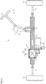
- an EPS 1 includes a steering mechanism 2 and an assist mechanism 3.
- the steering mechanism 2 steers steered wheels 15 in accordance with a steering operation that a user performs to control a steering wheel 10.
- the assist mechanism 3 assists the steering operation performed by a user.
- the steering mechanism 2 includes the steering wheel 10 and a steering shaft 11 that turns along with the steering wheel 10.
- the steering shaft 11 includes a column shaft 11a coupled to the steering wheel 10, an intermediate shaft 11b coupled to the bottom end of the column shaft 11 a, and a pinion shaft 11c coupled to the bottom end of the intermediate shaft 11b.
- the bottom end of the pinion shaft 11c is coupled through a rack and pinion mechanism 13 to a rack shaft 12 as a steered shaft.
- rotary motion of the steering shaft 11 is converted into reciprocating linear motion of the rack shaft 12 in an axial direction (right-left direction in FIG. 1 ) through the rack and pinion mechanism 13 that includes the pinion shaft 11c and the rack shaft 12.
- the rack shaft 12 is an example of a screw shaft.
- an axial direction refers to a direction along the axial length of the rack shaft 12, and a radial direction refers to a direction perpendicular to the axial direction.
- the assist mechanism 3 is provided in the vicinity of the rack shaft 12.
- the assist mechanism 3 includes a motor 20 as a source for generating an assisting force, a ball screw mechanism 30 integrally attached to the periphery of the rack shaft 12, and a belt-type reduction mechanism (hereinafter referred to as the "reduction mechanism") 40 for transmitting the rotational force of a rotating shaft 21 of the motor 20 to the ball screw mechanism 30.
- the assist mechanism 3 converts, through the reduction mechanism 40 and the ball screw mechanism 30, the rotational force of the rotating shaft 21 of the motor 20 into a force that causes the rack shaft 12 to reciprocate linearly in the axial direction.
- This axial force applied to the rack shaft 12 acts as the assisting force for assisting the steering operation performed by a user.
- the ball screw mechanism 30, the reduction mechanism 40, the pinion shaft 11c, and the rack shaft 12 are covered with a housing 16 that extends along the axial direction of the rack shaft 12.
- the housing 16 is divided in the axial direction at a position near the reduction mechanism 40 into a first housing 16a and a second housing 16b.
- the first housing 16a and the second housing 16b are coupled to form the housing 16.
- Each of the first and second housings 16a and 16b projects in a direction (i.e., in a downward direction in FIG. 1 ) intersecting with a direction that the rack shaft 12 extends in.
- the outer wall (the right side wall in FIG. 1 ) of the second housing 16b has a through hole 22.
- the rotating shaft 21 of the motor 20 extends into the second housing 16b through the through hole 22.
- a flange portion 17 of the second housing 16b and a flange portion 24 of the motor 20 are coupled together by a bolt 23 so that the motor 20 is fixed to the second housing 16b.
- the rotating shaft 21 is parallel to the rack shaft 12.
- the ball screw mechanism 30 includes a cylindrical nut 31 that is threadedly engaged with the rack shaft 12 through multiple balls 32.
- a helical screw groove 12a is provided on the outer circumferential surface of the rack shaft 12.
- a helical screw groove 33 corresponding to the screw groove 12a of the rack shaft 12 is provided on the inner circumferential surface of the nut 31.
- a helical space defined by the screw groove 33 of the nut 31 and the screw groove 12a of the rack shaft 12 serves as a rolling path R where the balls 32 roll.
- the nut 31 has a circulation path that connects two openings in the rolling path R.
- This structure allows the balls 32 to circulate endlessly in the rolling path R by way of the circulation path in the nut 31.
- the rolling path R is coated with a lubricant, such as grease, to reduce frictional resistance when the balls 32 roll.
- the rack shaft 12 and the nut 31 are each made of an iron alloy, such as a steel, and the balls 32 are made of a steel, such as a bearing steel.
- the reduction mechanism 40 includes a driving pulley 41 integrally attached to the rotating shaft 21 of the motor 20, a driven pulley 42 integrally attached to the outer periphery of the nut 31, and a belt 43 wrapped between the driving pulley 41 and the driven pulley 42.
- the belt 43 is a toothed rubber belt having a core wire.
- the driving pulley 41 and the driven pulley 42 are each a toothed pulley.
- the driven pulley 42 is supported by a cylindrical bearing 44 and is rotatable relative to the inner surface of the first housing 16a.
- the bearing 44 is a double-row angular contact ball bearing (a type of common, general-purpose bearing).
- the bearing 44 has load capacity that allows a continuous use of the bearing 44 even after the bearing 44 is subjected to the load (i.e., load rating) that the bearing 44 is expected to withstand a prescribed number of times without damage.
- a stopper ring 45 On the outer circumferential surface of the driven pulley 42, a stopper ring 45, a locking nut 46, and the bearing 44 are arranged in this order in the axial direction from the side opposite to the rack and pinion mechanism 13.
- the stopper ring 45 On the outer circumferential surface of the driven pulley 42, the stopper ring 45 is fitted into a flange portion located at an end of the driven pulley 42 that is opposite to the rack and pinion mechanism 13.
- a screw groove 48 threadedly engaged with a screw groove 47 on the outer circumferential surface of the driven pulley 42 is provided on the inner circumferential surface of the locking nut 46.
- the stopper ring 45 stops the locking nut 46 from coming off the outer circumferential surface of the driven pulley 42 because the stopper ring 45 is fitted into the flange portion located at the end of the driven pulley 42 that is opposite to the rack and pinion mechanism 13.
- An inner ring of the bearing 44 is fixed to the outer circumferential surface of the driven pulley 42 by being sandwiched between the locking nut 46 and a flange portion 42a of the driven pulley 42 that projects radially outward.
- An outer ring of the bearing 44 is fixed by being sandwiched between the first housing 16a and the second housing 16b through fixation members 49 that are provided on both axial sides of the outer ring.
- the nut 31 and a locking screw 34 are arranged in this order in the axial direction from the side opposite to the rack and pinion mechanism 13.
- a screw groove 36 threadedly engaged with a screw groove 35 on the inner circumferential surface of the driven pulley 42 is provided on the outer circumferential surface of the locking screw 34.
- the nut 31 is fixed to the inner circumferential surface of the driven pulley 42 by being sandwiched between the locking screw 34 and a flange portion 42b of the driven pulley 42 that projects radially inward.
- the nut 31 has a flanged end 31a projecting radially outward.
- the flanged end 31 a On the inner circumferential surface of the driven pulley 42, the flanged end 31 a abuts against a step portion 42c that has a wall toward the rack and pinion mechanism 13.
- the nut 31 has a shafted end 31b opposite to the flanged end 31a.
- the shafted end 31b On the inner circumferential surface of the driven pulley 42, the shafted end 31b abuts against the flange portion 42b. As such, the nut 31 is fixed to the driven pulley 42 in the axial direction, in the radial direction, and in a rotation direction about its axis.
- the driving pulley 41 rotates along with the rotating shaft 21.
- the rotation of the driving pulley 41 is transmitted to the driven pulley 42 through the belt 43.
- the driven pulley 42 rotates along with the nut 31. Since the nut 31 rotates relative to the rack shaft 12, the balls 32 interposed between the nut 31 and the rack shaft 12 are loaded by both the nut 31 and the rack shaft 12, thus circulating endlessly in the rolling path R.
- the rolling of the balls 32 in the rolling path R converts a torque applied to the nut 31 into the axial force applied to the rack shaft 12. Accordingly, the rack shaft 12 moves in the axial direction relative to the nut 31.
- the axial force applied to the rack shaft 12 acts as an assisting force and assists a steering operation performed by a user.
- a retainer 50 is provided between the outer circumferential surface of the rack shaft 12 and the inner circumferential surface of the nut 31. The retainer 50 retains the balls 32 to allow the balls 32 to avoid contact with each other.
- the retainer 50 is made of resin and has a cylindrical shape extending along the axial direction.
- One end of the retainer 50 in the axial direction is provided with a rib portion 51 that projects radially outward.
- the rib portion 51 extends continuously over the entire circumference of the retainer 50.
- the length of the retainer 50 in the axial direction is set such that the end provided with the rib portion 51 does not project beyond the flanged end 31a of the nut 31 in the axial direction and such that the other end opposite to the end provided with the rib portion 51 does not project beyond the shafted end 31b of the nut 31 in the axial direction.
- the rib portion 51 is located between the flanged end 31a of the nut 31 and the locking screw 34 to restrict the movement of the retainer 50 in the axial direction.
- the retainer 50 has multiple (16 in the embodiment) retainer grooves 52 that go through the retainer 50 in the radial direction and that are spaced at equal intervals in the circumferential direction of the retainer 50.
- the retainer grooves 52 extend along the axial direction of the retainer 50 and are inclined at a predetermined angle with respect to the axial direction of the retainer 50 in such a manner that the retainer grooves 52 intersect perpendicularly with a direction that the screw groove 33 of the nut 31 (i.e., the rolling path R) extends in.
- each of the retainer grooves 52 has a pair of tapered surfaces 52a and 52b that cause the retainer groove 52 to be tapered such that the width of the retainer groove 52 in the circumferential direction of the retainer 50 increases radially from the inner side to the outer side when viewed from the axial direction of the retainer 50.
- the pair of tapered surfaces 52a and 52b define the outline of the retainer groove 52 and are connected together at both axial ends of the retainer groove 52.
- a tapered angle ⁇ r formed by the pair of tapered surfaces 52a and 52b of the retainer groove 52 has a magnitude that causes a radially innermost width Wa of the retainer groove 52 to be smaller than the diameter of the balls 32 and that causes a radially outermost width Wb of the retainer groove 52 to be larger than the diameter of the balls 32.
- a predetermined number of balls 32 are located in each of the retainer grooves 52 and are spaced at equal intervals in the axial direction of the retainer 50.
- the equal interval corresponds to a so-called pitch, i.e., the distance between adjacent turns of the screw groove 33 on the inner circumferential surface of the nut 31.
- the balls 32 are spaced at equal intervals (i.e., intervals that the retainer grooves 52 are spaced at) in the circumferential direction of the retainer 50.
- the tapered angle ⁇ r and the groove widths Wa and Wb are set such that there is some clearance between the retainer groove 52 and the balls 32 when the nut 31 is threadedly engaged with the screw groove 12a of the rack shaft 12 through the balls 32.
- the retainer 50 is allowed to move to some extent in the radial direction, i.e., in a direction toward or away from the nut 31.
- the assist mechanism 3 when the assist mechanism 3 is mounted in such a manner that gravity acts downward in a vertical direction in FIG. 3 , the retainer 50 moves toward the balls 32 in the lower part of the drawing due to the weight of the retainer 50 as illustrated in FIG. 4B , so that the balls 32 abut against the pair of tapered surfaces 52a and 52b of the retainer groove 52. In this case, there is no clearance between the retainer 50 and the balls 32 in the lower part of the drawing.
- the remaining part other than those illustrated in FIGS. 4A and 4B includes both a situation where the balls 32 abut against the pair of tapered surfaces 52a and 52b of the retainer groove 52 and a situation where the pair of tapered surfaces 52a and 52b of the retainer groove 52 are spaced radially inward from the balls 32.
- the retainer 50 when the balls 32 are retained in the retainer grooves 52, the retainer 50 is radially supported by the balls 32, at least, in the lower part of the drawing while having some clearance with the balls 32, at least, in the upper part of the drawing. Further, when the components of the EPS 1 including the rack shaft 12 remain stationary, the retainer 50 is supported such that the inner circumferential surface and the outer circumferential surface of the retainer 50 are respectively spaced from the rack shaft 12 and the nut 31 so as to avoid contact with the rack shaft 12 and the nut 31.
- the retainer 50 may be inclined with respect to the nut 31 in such a manner that part of the axial ends of the retainer 50 approaches part of the axial ends of the nut 31 in the radial direction.
- the nut 31 has a structure that allows a reduction in contact between the nut 31 and the retainer 50 when the retainer 50 is inclined with respect to the nut 31.
- the description below details the structure of the nut 31 that allows a reduction in contact between the nut 31 and the retainer 50 when the retainer 50 is inclined with respect to the nut 31.
- the nut 31 has a uniform diameter portion 60 and a pair of enlarged diameter portions 70 and 80.
- the inside diameter of the uniform diameter portion 60 is uniform, and the inside diameters of the pair of enlarged diameter portions 70 and 80 are each larger than that of the uniform diameter portion 60.
- the pair of enlarged diameter portions 70 and 80 are provided at both axial sides of the uniform diameter portion 60.
- the enlarged diameter portion 70 is provided at one side provided with the flanged end 31a of the nut 31 and includes the flanged end 31 a
- the enlarged diameter portion 80 is provided at the other side provided with the shafted end 31b of the nut 31 and includes the shafted end 31b.
- the inside diameter of the nut 31 is measured at the crest of a screw thread 33a on the inner circumferential surface of the nut 31.
- the inner circumferential surface of the enlarged diameter portion 70 includes a tapered portion that increases in inside diameter toward an end face of one of the opposite axial ends of the nut 31 that is closer to the enlarged diameter portion 70 than to the enlarged diameter portion 80.
- the inner circumferential surface of the enlarged diameter portion 80 has a tapered portion that increases in inside diameter toward an end face of the other of the opposite axial ends of the nut 31 that is closer to the enlarged diameter portion 80 than to the enlarged diameter portion 70.
- the enlarged diameter portion 70 includes a first enlarged diameter portion 71 adjoining to an end face of the flanged end 31a and a second enlarged diameter portion 72 adjoining to the first enlarged diameter portion 71.
- the first enlarged diameter portion 71 includes a tapered portion 71 a that has a uniform diameter within a predetermined distance from the end face of the flanged end 31 a and that is tapered, beyond the predetermined distance, to form an inclination angle ⁇ a, i.e., to form a tapered angle 2 ⁇ a (double the inclination angle ⁇ a) with respect to the axial direction of the nut 31.
- the second enlarged diameter portion 72 includes a tapered portion 72a that is tapered to form an inclination angle ⁇ b, i.e., to form a tapered angle 2 ⁇ b (double the inclination angle ⁇ b) with respect to the axial direction of the nut 31.
- the tapered angle 2 ⁇ b (the inclination angle ⁇ b) of the tapered portion 72a of the second enlarged diameter portion 72 is smaller than the tapered angle 2 ⁇ a (the inclination angle ⁇ a) of the tapered portion 71a of the first enlarged diameter portion 71.
- the inner circumferential surface of the enlarged diameter portion 70 has two different inclination angles, i.e., two different tapered angles (one is defined by the first enlarged diameter portion 71, the other is defined by the second enlarged diameter portion 72) with respect to the axial direction of the nut 31, and the inside diameter of the enlarged diameter portion 70 changes at two different rates such that the inclination is larger on the flanged end 31a side.
- the enlarged diameter portion 80 includes a first enlarged diameter portion 81 adjoining to an end face of the shafted end 31b and a second enlarged diameter portion 82 adjoining to the first enlarged diameter portion 81.
- the first enlarged diameter portion 81 includes a tapered portion 81 a that has a uniform diameter within a predetermined distance from the end face of the shafted end 31b and that is tapered, beyond the predetermined distance, to form an inclination angle ⁇ c, i.e., to form a tapered angle 2 ⁇ c (double the inclination angle ⁇ c) with respect to the axial direction of the nut 31.
- the inclination angle ⁇ c is different in magnitude from the inclination angle ⁇ a.
- the second enlarged diameter portion 82 includes a tapered portion 82a that is tapered to form an inclination angle ⁇ d, i.e., to form a tapered angle 2 ⁇ d (double the inclination angle ⁇ d) with respect to the axial direction of the nut 31.
- the inclination angle ⁇ d is equal in magnitude to the inclination angle ⁇ b.
- the tapered angle 2 ⁇ d (the inclination angle ⁇ d) of the tapered portion 82a of the second enlarged diameter portion 82 is smaller than the tapered angle 2 ⁇ c (the inclination angle ⁇ c) of the tapered portion 81 a of the first enlarged diameter portion 81.
- the inner circumferential surface of the enlarged diameter portion 80 has two different inclination angles, i.e., two different tapered angles (one is defined by the first enlarged diameter portion 81, the other is defined by the second enlarged diameter portion 82) with respect to the axial direction of the nut 31, and the inside diameter of the enlarged diameter portion 80 changes at two different rates such that the inclination is larger on the shafted end 31b side.
- the enlarged diameter portions 70 and 80 are respectively provided at the axial ends 31a and 31 b in a region on the inner circumferential surface of the nut 31 that faces the retainer grooves 52 and retainer ends adjoining to opposite axial ends of the retainer grooves 52 when the retainer 50 is located between the outer circumferential surface of the rack shaft 12 and the inner circumferential surface of the nut 31.
- the first enlarged diameter portion 71 is provided in a region S1 on the inner circumferential surface of the nut 31 that has no screw thread 33a and that extends from the end face of one of the opposite axial ends of the nut 31 that is closer to the first enlarged diameter portion 71 than to the first enlarged diameter portion 81.
- the first enlarged diameter portion 81 is provided in a region S1 on the inner circumferential surface of the nut 31 that has no screw thread 33a and that extends from the end face of the other of the opposite axial ends of the nut 31 that is closer to the first enlarged diameter portion 81 than to the first enlarged diameter portion 71.
- the first enlarged diameter portion 81 provided at the shafted end 31b of the nut 31 is provided in a region on the inner circumferential surface of the nut 31 that faces neither the retainer grooves 52 nor the retainer ends adjoining to the opposite axial ends of the retainer grooves 52 when the retainer 50 is located between the outer circumferential surface of the rack shaft 12 and the inner circumferential surface of the nut 31.
- the first enlarged diameter portion 81 is provided in a region on the inner circumferential surface of the nut 31 that does not face the retainer 50.
- the region that has no screw thread 33a of the nut 31 allows part of a cutting tool for machining the nut 31 to be inserted into the nut 31 to provide the screw groove 33.
- the cutting tool has a rod shape and includes: a mounting portion attached to a main shaft of a machine tool; a cutting portion for cutting the screw groove 33; and a tapered portion that is located between the mounting portion and the cutting portion and that decreases in outside diameter in a direction from the mounting portion to the cutting portion.
- the inclination angles ⁇ a and ⁇ c of the first enlarged diameter portions 71 and 81 are set to magnitudes that allow the first enlarged diameter portions 71 and 81 to avoid contact with the cutting tool having the tapered portion when the cutting tool is inserted into the nut 31 from the axial ends of the nut 31.
- the magnitudes of the inclination angles ⁇ a and ⁇ c that allow the first enlarged diameter portions 71 and 81 to avoid contact with the cutting tool are empirically determined with consideration of factors including the tapered angle and shape of the tapered portion of the cutting tool.
- the first enlarged diameter portions 71 and 81 (the tapered portions 71a and 81a) have different inclination angles ⁇ a and ⁇ c and different shapes.
- Each of the second enlarged diameter portions 72 and 82 is provided in a region on the inner circumferential surface of the nut 31 that has the screw thread 33a of the nut 31 and where no ball 32 is located when the nut 31 is threadedly engaged with the screw groove 12a of the rack shaft 12 through the balls 32.
- boundary lines L1 and L2 are defined as lines extending perpendicular to the axial direction of the nut 31 and passing different axial ends of a region on the inner circumferential surface of the nut 31 where the balls 32 are located
- the second enlarged diameter portion 72 is provided in a region S2 on the inner circumferential surface of the nut 31 that extend, to the first enlarged diameter portion 71, from the boundary line L1 toward the end face of one of the axial ends of the nut 31 that is closer to the boundary line L1 than to the boundary line L2.
- the second enlarged diameter portion 82 is provided in a region S2 on the inner circumferential surface of the nut 31 that extend, to the first enlarged diameter portion 81, from the boundary line L2 toward the end face of the other of the axial ends of the nut 31 that is closer to the boundary line L2 than to the boundary line L1.
- the uniform diameter portion 60 is provided in a region S0 on the inner circumferential surface of the nut 31 that has the screw thread 33a of the nut 31 and where the balls 32 are located when the nut 31 is threadedly engaged with the screw groove 12a of the rack shaft 12 through the balls 32.
- the height of the crest of turns (two turns in the embodiment) of the screw thread 33a of the nut 31 in the second enlarged diameter portions 72 and 82 is set smaller than that when the uniform diameter portion 60 is elongated over the entire axial length of the nut 31.
- the crest of the screw thread 33a formed by cutting the screw groove 33 in the nut 31 is further cut down radially outward.
- the inclination angles ⁇ b and ⁇ d of the second enlarged diameter portions 72 and 82 are set to magnitudes that allow the second enlarged diameter portions 72 and 82 to avoid contact with the retainer 50 when the retainer 50 is inclined with respect to the nut 31 such that part of the axial ends of the retainer 50 approaches part of the axial ends of the nut 31.
- the magnitudes of the inclination angles ⁇ b and ⁇ d that allow the second enlarged diameter portions 72 and 82 to avoid contact with the retainer 50 are determined by adding some margin to magnitudes that are geometrically determined from the axial length of the retainer 50, the clearance between the retainer 50 and the balls 32, the clearance between the inner circumferential surface of the retainer 50 and the rack shaft 12, and the clearance between the outer circumferential surface of the retainer 50 and the nut 31.
- the embodiment described above has the following effects (1) to (5).
- (1) As illustrated in FIG. 2 and FIG. 3 , when the retainer 50 is not inclined with respect to the nut 31, there is some clearance between the outer circumferential surface of the retainer 50 and the nut 31. In contrast, when the retainer 50 is inclined with respect to the nut 31, part of the axial ends of the retainer 50 approach part of the axial ends of the nut 31 in a space between the retainer 50 and the nut 31.
- the outer circumferential surface in the vicinity of the axial ends of the retainer 50 may enter regions (hatched regions in FIGS. 6A and 6B ) that have the tapered angles 2 ⁇ b and 2 ⁇ d with respect to the uniform diameter portion 60 and that have the screw thread 33a whose crest is cut down. It is noted that for convenience in description, the nut 31 and the retainer 50 in FIGS. 6A and 6B are illustrated in a simplified manner.
- the first enlarged diameter portions 71 and 81 respectively have the tapered portions 71 a and 81 a that increase in inside diameter toward the end faces of their respective closer axial ends of the nut 31, and the second enlarged diameter portions 72 and 82 respectively have the tapered portions 72a and 82a that increase in inside diameter toward the end faces of their respective closer axial ends of the nut 31.
- This structure allows a reduction in contact between the axial ends of the retainer 50 and the axial ends of the nut 31 in the second enlarged diameter portions 72 and 82 of the nut 31 when the retainer 50 is inclined with respect to the nut 31 as illustrated in FIGS. 6A and 6B , for example, regardless of whether the axial ends of the retainer 50 are elongated or shortened.
- the embodiment makes it possible to relax the limitations of the specifications of the retainer 50, including the length, that are required to reduce contact between the nut 31 and the cutting tool used to provide the screw groove 33 on the inner circumferential surface of the nut 31 and that are required to reduce contact between the retainer 50 and the nut 31.
- the height of the screw thread 33a in the second enlarged diameter portions 72 and 82 in the radial direction of the nut 31 is smaller than that of the screw thread 33a in the uniform diameter portion 60.
- the height of the screw thread 33a in the second enlarged diameter portions 72 and 82 in the radial direction of the nut 31 changes at a rate smaller than that when the first enlarged diameter portions 71 and 81 are elongated in the axial direction.
- the second enlarged diameter portions 72 and 82 are provided in the region S2 where no ball 32 is located.
- the second enlarged diameter portions 72 and 82 may abut against the balls 32 at the screw thread 33a adjacent to the boundary lines L1 and L2 (i.e., at the screw thread 33a located on the near side of the cross-section in FIG. 5 ) on the boundary lines L1 and L2 sides.
- the screw thread 33a is lower in the second enlarged diameter portions 72 and 82 than in the uniform diameter portion 60, the screw thread 33a in the second enlarged diameter portions 72 and 82 reduces an increase in stress due to load applied to the balls 32.
- One of the axial ends of the retainer 50 is provided with the enlarged diameter portion 70, i.e., the second enlarged diameter portion 72, and the other of the axial ends of the retainer 50 is provided with the enlarged diameter portion 80, i.e., the second enlarged diameter portion 82.
- the enlarged diameter portion 70 i.e., the second enlarged diameter portion 72
- the other of the axial ends of the retainer 50 is provided with the enlarged diameter portion 80, i.e., the second enlarged diameter portion 82.
- the EPS 1 having the ball screw mechanism 30 according to the embodiment reduces contact between the retainer 50 and the nut 31, thus reducing the influence of such contact on steering feel. Further, when the contact between the retainer 50 and the nut 31 is reduced, noise caused from the contact is reduced accordingly, so that quietness of the EPS 1 is improved.
- the embodiment described above can be modified in various ways. Some examples of modifications are described below.
- the nut 31 may have only one of the enlarged diameter portions 70 and 80.
- the nut 31 may have no enlarged diameter portion 70 at the flanged end 31a.
- the magnitudes of the inclination angles i.e., the tapered angles of the first enlarged diameter portions 71 and 81 and the second enlarged diameter portions 72 and 82 can be changed as needed.
- the relationship between the tapered angle 2 ⁇ a and the tapered angle 2 ⁇ b, the relationship between the tapered angle 2 ⁇ a and the tapered angle 2 ⁇ c, the relationship between the tapered angle 2 ⁇ b and the tapered angle 2 ⁇ d, and the relationship between the tapered angle 2 ⁇ c and the tapered angle 2 ⁇ d may be changed.
- the second enlarged diameter portions 72 and 82 of the nut 31 can be provided in regions other than the region S2.
- the second enlarged diameter portions 72 and 82 may be provided in regions that has no screw thread 33a of the nut 31.
- the second enlarged diameter portions 72 and 82 may be provided in regions where the balls 32 are located.
- the second enlarged diameter portions 72 and 82 may extend from positions away from the boundary lines L1 and L2 illustrated in FIG. 5 , toward the end faces of their respective closer ends of the nut 31.
- the first enlarged diameter portions 71 and 81 may include regions that have the screw thread 33a of the nut 31. Any one of the enlarged diameter portions 70 and 80 may have no second enlarged diameter portion. At least one of the enlarged diameter portions 70 and 80 may have none of the first enlarged diameter portions 71 and 81.
- the enlarged diameter portions 70 and 80 may have the same shape.
- the enlarged diameter portions 70 and 80 may have more than two tapered angles.
- the enlarged diameter portions 70 and 80 may have no tapered portion as long as the inside diameters of the enlarged diameter portions 70 and 80 are larger than the inside diameter of the uniform diameter portion 60.
- each of the enlarged diameter portions 70 and 80 may have a uniform diameter portion with a uniform inside diameter in their middle part or may have multiple uniform diameter portions with different inside diameters that are combined to change their inside diameter stepwise.
- the first enlarged diameter portions 71 and 81 of the enlarged diameter portions 70 and 80 are not essential elements, and the enlarged diameter portions 70 and 80 may have only the second enlarged diameter portions 72 and 82, respectively.
- the first enlarged diameter portions 71 and 81 are structured to have a uniform diameter. This structure reduces contact between the axial ends of the retainer 50 and the axial ends of the nut 31 provided with the second enlarged diameter portions 72 and 82, thus reducing contact and friction between the retainer 50 and the nut 31.
- the specifications of the retainer 50 can be modified as needed.
- the retainer 50 may have such a length that the end of the retainer 50, opposite to the rib portion 51, reaches the first enlarged diameter portion 81 of the nut 31. This structure achieves effects similar to those of the embodiment.
- the retainer 50 may have no rib portion 51. In this case, restricting the axial movement of the retainer 50 by adding a stopper ring to the inner periphery of the nut 31 can achieve effects similar to those of the embodiment.
- the retainer 50 may be made of metal or composite materials.
- the nut 31 may be supported directly by the bearing 44.
- the bearing 44 not only the bearing 44 but also the driven pulley 42 are fixed to the outer circumferential surface of the nut 31. This structure achieves effects similar to those of the embodiment.
- the ball screw mechanism 30 can be used for any other system that has a mechanism for converting rotary motion into linear motion.
- the ball screw mechanism 30 may be used for machine tools and microscopes.
- a steering system as the EPS 1, but a steering system is not limited to an EPS.
- a steering system may be embodied as a steer-by-wire steering system.
- a steering system may be embodied as a rear wheel steering system or a four-wheel steering (4WS) system.
- SBW steer-by-wire
- 4WS four-wheel steering
- a steering system is embodied as a steer-by-wire steering system, a shaft having no rack can be employed as a steered shaft instead of the rack shaft 12 having a rack.
- the ball screw mechanism 30 is used to apply a steered force to the shaft as a steered shaft.
Landscapes
- Engineering & Computer Science (AREA)
- General Engineering & Computer Science (AREA)
- Mechanical Engineering (AREA)
- Chemical & Material Sciences (AREA)
- Combustion & Propulsion (AREA)
- Transportation (AREA)
- Transmission Devices (AREA)
- Power Steering Mechanism (AREA)
Abstract
Description
- The invention relates to a ball screw mechanism and a steering system.
- Some ball screw mechanisms include a screw shaft with a helical screw groove on the outer circumferential surface and a nut with a helical screw groove corresponding to the screw groove of the screw shaft. When the nut is threadedly engaged with the screw groove of the screw shaft through balls, an axial force is applied to the screw shaft in accordance with rotation of the nut. This type of ball screw mechanism is used in steering systems that steer steered wheels by converting rotary motion of a motor into linear motion of a steered shaft, such as a rack shaft, as disclosed in, for example, Japanese Patent Application Publication No.
2015-186949 JP 2015-186949 A 5120040 JP 5120040 - A nut used in the ball screw mechanism disclosed in
JP 2015-186949 A JP 5120040 - For example, to allow for tolerances of the retainer, the balls, and the screw grooves of the screw shaft and the nut, the dimensions of the retainer disclosed in
JP 5120040 JP 2015-186949 A - A purpose of the invention is to provide a ball screw mechanism and a steering system that allow a reduction in contact and friction between a retainer and a nut.
- An aspect of the invention provides a ball screw mechanism including: a screw shaft having an outer circumferential surface provided with a helical screw groove; a cylindrical nut having an inner circumferential surface provided with a helical screw groove corresponding to the screw groove of the screw shaft; multiple balls; and a cylindrical retainer provided between the screw shaft and the nut. The retainer has a retainer groove that retains the balls to allow the balls to avoid contact with each other. The nut is threadedly engaged with the screw groove of the screw shaft through the balls. An axial force is applied to the screw shaft in accordance with rotation of the nut. The nut includes a uniform diameter portion and an enlarged diameter portion. The uniform diameter portion has a uniform inside diameter. The enlarged diameter portion has an inside diameter larger than the inside diameter of the uniform diameter portion. The enlarged diameter portion is provided at at least one of opposite axial ends of a region on the inner circumferential surface of the nut. The region faces the retainer groove and retainer ends adjoining to opposite axial ends of the retainer groove.
- The retainer may be inclined with respect to the nut when dimensions are set such that there is some clearance between the retainer groove and the balls to allow for tolerances of the retainer, the balls, the screw grooves of the screw shaft and the nut. If such situation occurs, the axial ends of the retainer may approach and come into contact with the axial ends of the nut in a radial direction.
- According to this aspect, when the axial ends of the retainer approach the axial ends of the nut, the axial end of the nut provided with the enlarged diameter portion is less likely to come into contact with the axial end of the retainer. This allows a reduction in contact and friction between the retainer and the nut, thus making it possible to reduce a friction torque of the nut.
- The foregoing and further features and advantages of the invention will become apparent from the following description of example embodiments with reference to the accompanying drawings, wherein like numerals are used to represent like elements and wherein:
-
FIG. 1 is a schematic diagram illustrating the structure of an electric power steering system; -
FIG. 2 is a schematic diagram illustrating the structure of an assist mechanism of the electric power steering system; -
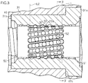
FIG. 3 is a schematic diagram illustrating the structure of a retainer of the assist mechanism; -
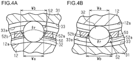
FIG. 4A is a cross-sectional view of part of the retainer inFIG. 3 taken along line IV-IV inFIG. 3 ; -
FIG. 4B is a cross-sectional view of part of the retainer inFIG. 3 taken along line IV-IV inFIG. 3 ; -
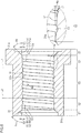
FIG. 5 is a cross-sectional view of the structure of a nut; -
FIG. 6A is a diagram schematically illustrating a situation where the retainer is inclined with respect to the nut; and -
FIG. 6B is a diagram schematically illustrating a situation where the retainer is inclined with respect to the nut. - Below, a ball screw mechanism and a steering system according to an embodiment of the invention is described. The steering system according to the embodiment is an electric power steering system (hereinafter referred to as "EPS") that assists steering operation of a user by transmitting rotary motion of a motor to the ball screw mechanism through a belt reduction mechanism so as to convert the rotary motion of the motor into linear motion of a rack shaft.
- As shown in
FIG. 1 , anEPS 1 includes asteering mechanism 2 and anassist mechanism 3. Thesteering mechanism 2 steers steeredwheels 15 in accordance with a steering operation that a user performs to control asteering wheel 10. Theassist mechanism 3 assists the steering operation performed by a user. - The
steering mechanism 2 includes thesteering wheel 10 and asteering shaft 11 that turns along with thesteering wheel 10. Thesteering shaft 11 includes acolumn shaft 11a coupled to thesteering wheel 10, anintermediate shaft 11b coupled to the bottom end of thecolumn shaft 11 a, and apinion shaft 11c coupled to the bottom end of theintermediate shaft 11b. The bottom end of thepinion shaft 11c is coupled through a rack andpinion mechanism 13 to arack shaft 12 as a steered shaft. Thus, rotary motion of thesteering shaft 11 is converted into reciprocating linear motion of therack shaft 12 in an axial direction (right-left direction inFIG. 1 ) through the rack andpinion mechanism 13 that includes thepinion shaft 11c and therack shaft 12. The reciprocating linear motion is transmitted to the right and left steeredwheels 15 throughtie rods 14 coupled to both ends of therack shaft 12, thus changing a steered angle of the steeredwheels 15. According to the embodiment, therack shaft 12 is an example of a screw shaft. - In the description below, an axial direction refers to a direction along the axial length of the
rack shaft 12, and a radial direction refers to a direction perpendicular to the axial direction. Theassist mechanism 3 is provided in the vicinity of therack shaft 12. Theassist mechanism 3 includes amotor 20 as a source for generating an assisting force, aball screw mechanism 30 integrally attached to the periphery of therack shaft 12, and a belt-type reduction mechanism (hereinafter referred to as the "reduction mechanism") 40 for transmitting the rotational force of a rotatingshaft 21 of themotor 20 to theball screw mechanism 30. Theassist mechanism 3 converts, through thereduction mechanism 40 and theball screw mechanism 30, the rotational force of the rotatingshaft 21 of themotor 20 into a force that causes therack shaft 12 to reciprocate linearly in the axial direction. This axial force applied to therack shaft 12 acts as the assisting force for assisting the steering operation performed by a user. - The
ball screw mechanism 30, thereduction mechanism 40, thepinion shaft 11c, and therack shaft 12 are covered with ahousing 16 that extends along the axial direction of therack shaft 12. Thehousing 16 is divided in the axial direction at a position near thereduction mechanism 40 into a first housing 16a and asecond housing 16b. The first housing 16a and thesecond housing 16b are coupled to form thehousing 16. Each of the first andsecond housings 16a and 16b projects in a direction (i.e., in a downward direction inFIG. 1 ) intersecting with a direction that therack shaft 12 extends in. The outer wall (the right side wall inFIG. 1 ) of thesecond housing 16b has a throughhole 22. The rotatingshaft 21 of themotor 20 extends into thesecond housing 16b through the throughhole 22. Aflange portion 17 of thesecond housing 16b and aflange portion 24 of themotor 20 are coupled together by abolt 23 so that themotor 20 is fixed to thesecond housing 16b. The rotatingshaft 21 is parallel to therack shaft 12. - Next, the
assist mechanism 3 is described in detail. As shown inFIG. 2 , theball screw mechanism 30 includes acylindrical nut 31 that is threadedly engaged with therack shaft 12 throughmultiple balls 32. Ahelical screw groove 12a is provided on the outer circumferential surface of therack shaft 12. Ahelical screw groove 33 corresponding to thescrew groove 12a of therack shaft 12 is provided on the inner circumferential surface of thenut 31. A helical space defined by thescrew groove 33 of thenut 31 and thescrew groove 12a of therack shaft 12 serves as a rolling path R where theballs 32 roll. Although not shown in the drawings, thenut 31 has a circulation path that connects two openings in the rolling path R. This structure allows theballs 32 to circulate endlessly in the rolling path R by way of the circulation path in thenut 31. The rolling path R is coated with a lubricant, such as grease, to reduce frictional resistance when theballs 32 roll. Therack shaft 12 and thenut 31 are each made of an iron alloy, such as a steel, and theballs 32 are made of a steel, such as a bearing steel. - The
reduction mechanism 40 includes a drivingpulley 41 integrally attached to therotating shaft 21 of themotor 20, a drivenpulley 42 integrally attached to the outer periphery of thenut 31, and abelt 43 wrapped between the drivingpulley 41 and the drivenpulley 42. Thebelt 43 is a toothed rubber belt having a core wire. The drivingpulley 41 and the drivenpulley 42 are each a toothed pulley. - The driven
pulley 42 is supported by acylindrical bearing 44 and is rotatable relative to the inner surface of the first housing 16a. For example, thebearing 44 is a double-row angular contact ball bearing (a type of common, general-purpose bearing). Thebearing 44 has load capacity that allows a continuous use of thebearing 44 even after thebearing 44 is subjected to the load (i.e., load rating) that thebearing 44 is expected to withstand a prescribed number of times without damage. - On the outer circumferential surface of the driven
pulley 42, astopper ring 45, a lockingnut 46, and thebearing 44 are arranged in this order in the axial direction from the side opposite to the rack andpinion mechanism 13. On the outer circumferential surface of the drivenpulley 42, thestopper ring 45 is fitted into a flange portion located at an end of the drivenpulley 42 that is opposite to the rack andpinion mechanism 13. Ascrew groove 48 threadedly engaged with ascrew groove 47 on the outer circumferential surface of the drivenpulley 42 is provided on the inner circumferential surface of the lockingnut 46. Thestopper ring 45 stops the lockingnut 46 from coming off the outer circumferential surface of the drivenpulley 42 because thestopper ring 45 is fitted into the flange portion located at the end of the drivenpulley 42 that is opposite to the rack andpinion mechanism 13. An inner ring of thebearing 44 is fixed to the outer circumferential surface of the drivenpulley 42 by being sandwiched between the lockingnut 46 and aflange portion 42a of the drivenpulley 42 that projects radially outward. An outer ring of thebearing 44 is fixed by being sandwiched between the first housing 16a and thesecond housing 16b throughfixation members 49 that are provided on both axial sides of the outer ring. - On the inner circumferential surface of the driven
pulley 42, thenut 31 and a lockingscrew 34 are arranged in this order in the axial direction from the side opposite to the rack andpinion mechanism 13. Ascrew groove 36 threadedly engaged with ascrew groove 35 on the inner circumferential surface of the drivenpulley 42 is provided on the outer circumferential surface of the lockingscrew 34. Thenut 31 is fixed to the inner circumferential surface of the drivenpulley 42 by being sandwiched between the lockingscrew 34 and aflange portion 42b of the drivenpulley 42 that projects radially inward. Thenut 31 has a flanged end 31a projecting radially outward. On the inner circumferential surface of the drivenpulley 42, the flanged end 31 a abuts against astep portion 42c that has a wall toward the rack andpinion mechanism 13. Thenut 31 has a shaftedend 31b opposite to the flanged end 31a. On the inner circumferential surface of the drivenpulley 42, theshafted end 31b abuts against theflange portion 42b. As such, thenut 31 is fixed to the drivenpulley 42 in the axial direction, in the radial direction, and in a rotation direction about its axis. - Thus, when the rotating
shaft 21 of themotor 20 rotates, the drivingpulley 41 rotates along with the rotatingshaft 21. The rotation of the drivingpulley 41 is transmitted to the drivenpulley 42 through thebelt 43. Accordingly, the drivenpulley 42 rotates along with thenut 31. Since thenut 31 rotates relative to therack shaft 12, theballs 32 interposed between thenut 31 and therack shaft 12 are loaded by both thenut 31 and therack shaft 12, thus circulating endlessly in the rolling path R. The rolling of theballs 32 in the rolling path R converts a torque applied to thenut 31 into the axial force applied to therack shaft 12. Accordingly, therack shaft 12 moves in the axial direction relative to thenut 31. The axial force applied to therack shaft 12 acts as an assisting force and assists a steering operation performed by a user. Aretainer 50 is provided between the outer circumferential surface of therack shaft 12 and the inner circumferential surface of thenut 31. Theretainer 50 retains theballs 32 to allow theballs 32 to avoid contact with each other. - Next, the
retainer 50 is described in detail. As illustrated inFIG. 2 andFIG. 3 , theretainer 50 is made of resin and has a cylindrical shape extending along the axial direction. One end of theretainer 50 in the axial direction is provided with arib portion 51 that projects radially outward. Therib portion 51 extends continuously over the entire circumference of theretainer 50. The length of theretainer 50 in the axial direction is set such that the end provided with therib portion 51 does not project beyond the flanged end 31a of thenut 31 in the axial direction and such that the other end opposite to the end provided with therib portion 51 does not project beyond theshafted end 31b of thenut 31 in the axial direction. Therib portion 51 is located between the flanged end 31a of thenut 31 and the lockingscrew 34 to restrict the movement of theretainer 50 in the axial direction. - The
retainer 50 has multiple (16 in the embodiment)retainer grooves 52 that go through theretainer 50 in the radial direction and that are spaced at equal intervals in the circumferential direction of theretainer 50. Theretainer grooves 52 extend along the axial direction of theretainer 50 and are inclined at a predetermined angle with respect to the axial direction of theretainer 50 in such a manner that theretainer grooves 52 intersect perpendicularly with a direction that thescrew groove 33 of the nut 31 (i.e., the rolling path R) extends in. - The structure of the
retainer grooves 52 is described in further detail below. As illustrated inFIGS. 4A and 4B , each of theretainer grooves 52 has a pair of taperedsurfaces retainer groove 52 to be tapered such that the width of theretainer groove 52 in the circumferential direction of theretainer 50 increases radially from the inner side to the outer side when viewed from the axial direction of theretainer 50. The pair of taperedsurfaces retainer groove 52 and are connected together at both axial ends of theretainer groove 52. A tapered angle θr formed by the pair of taperedsurfaces retainer groove 52 has a magnitude that causes a radially innermost width Wa of theretainer groove 52 to be smaller than the diameter of theballs 32 and that causes a radially outermost width Wb of theretainer groove 52 to be larger than the diameter of theballs 32. - As illustrated in
FIG. 3 andFIGS. 4A and 4B , a predetermined number ofballs 32 are located in each of theretainer grooves 52 and are spaced at equal intervals in the axial direction of theretainer 50. The equal interval corresponds to a so-called pitch, i.e., the distance between adjacent turns of thescrew groove 33 on the inner circumferential surface of thenut 31. Further, theballs 32 are spaced at equal intervals (i.e., intervals that theretainer grooves 52 are spaced at) in the circumferential direction of theretainer 50. Thus, when theballs 32 are located in theretainer grooves 52, theballs 32 are retained such that each of theballs 32 avoids contact with anyother balls 32. In this case, theballs 32 are allowed to move in the radially outward direction of theretainer 50 and are restricted to move in the radially inward direction of theretainer 50. - To allow for tolerances of the
retainer 50, theballs 32, thescrew groove 12a of therack shaft 12, and thescrew groove 33 of thenut 31, the tapered angle θr and the groove widths Wa and Wb are set such that there is some clearance between theretainer groove 52 and theballs 32 when thenut 31 is threadedly engaged with thescrew groove 12a of therack shaft 12 through theballs 32. In this case, theretainer 50 is allowed to move to some extent in the radial direction, i.e., in a direction toward or away from thenut 31. - For example, when the
assist mechanism 3 is mounted in such a manner that gravity acts downward in a vertical direction inFIG. 3 , theretainer 50 moves toward theballs 32 in the lower part of the drawing due to the weight of theretainer 50 as illustrated inFIG. 4B , so that theballs 32 abut against the pair of taperedsurfaces retainer groove 52. In this case, there is no clearance between theretainer 50 and theballs 32 in the lower part of the drawing. - In contrast, as illustrated in
FIG. 4A , since theretainer 50 moves toward theballs 32 in the lower part of the drawing due to the weight of theretainer 50, the pair of taperedsurfaces retainer groove 52 are spaced radially inward from theballs 32 in the upper part of the drawing accordingly. In this case, there is some clearance between theretainer 50 and theballs 32 in the upper part of the drawing. - The remaining part other than those illustrated in
FIGS. 4A and 4B includes both a situation where theballs 32 abut against the pair of taperedsurfaces retainer groove 52 and a situation where the pair of taperedsurfaces retainer groove 52 are spaced radially inward from theballs 32. - Thus, when the
balls 32 are retained in theretainer grooves 52, theretainer 50 is radially supported by theballs 32, at least, in the lower part of the drawing while having some clearance with theballs 32, at least, in the upper part of the drawing. Further, when the components of theEPS 1 including therack shaft 12 remain stationary, theretainer 50 is supported such that the inner circumferential surface and the outer circumferential surface of theretainer 50 are respectively spaced from therack shaft 12 and thenut 31 so as to avoid contact with therack shaft 12 and thenut 31. In this case, due to the clearance between theretainer 50 and theballs 32, the clearance between the inner circumferential surface of theretainer 50 and therack shaft 12, and the clearance between the outer circumferential surface of theretainer 50 and thenut 31, theretainer 50 may be inclined with respect to thenut 31 in such a manner that part of the axial ends of theretainer 50 approaches part of the axial ends of thenut 31 in the radial direction. In this regard, according to the embodiment, thenut 31 has a structure that allows a reduction in contact between thenut 31 and theretainer 50 when theretainer 50 is inclined with respect to thenut 31. - The description below details the structure of the
nut 31 that allows a reduction in contact between thenut 31 and theretainer 50 when theretainer 50 is inclined with respect to thenut 31. As shown inFIG. 5 , thenut 31 has auniform diameter portion 60 and a pair ofenlarged diameter portions nut 31, the inside diameter of theuniform diameter portion 60 is uniform, and the inside diameters of the pair ofenlarged diameter portions uniform diameter portion 60. The pair ofenlarged diameter portions uniform diameter portion 60. Specifically, theenlarged diameter portion 70 is provided at one side provided with the flanged end 31a of thenut 31 and includes the flanged end 31 a, and theenlarged diameter portion 80 is provided at the other side provided with theshafted end 31b of thenut 31 and includes theshafted end 31b. It is noted that the inside diameter of thenut 31 is measured at the crest of ascrew thread 33a on the inner circumferential surface of thenut 31. The inner circumferential surface of theenlarged diameter portion 70 includes a tapered portion that increases in inside diameter toward an end face of one of the opposite axial ends of thenut 31 that is closer to theenlarged diameter portion 70 than to theenlarged diameter portion 80. Likewise, the inner circumferential surface of theenlarged diameter portion 80 has a tapered portion that increases in inside diameter toward an end face of the other of the opposite axial ends of thenut 31 that is closer to theenlarged diameter portion 80 than to theenlarged diameter portion 70. - The
enlarged diameter portion 70 includes a firstenlarged diameter portion 71 adjoining to an end face of the flanged end 31a and a secondenlarged diameter portion 72 adjoining to the firstenlarged diameter portion 71. The firstenlarged diameter portion 71 includes a taperedportion 71 a that has a uniform diameter within a predetermined distance from the end face of the flanged end 31 a and that is tapered, beyond the predetermined distance, to form an inclination angle θa, i.e., to form a tapered angle 2θa (double the inclination angle θa) with respect to the axial direction of thenut 31. The secondenlarged diameter portion 72 includes a taperedportion 72a that is tapered to form an inclination angle θb, i.e., to form a tapered angle 2θb (double the inclination angle θb) with respect to the axial direction of thenut 31. The tapered angle 2θb (the inclination angle θb) of the taperedportion 72a of the secondenlarged diameter portion 72 is smaller than the tapered angle 2θa (the inclination angle θa) of the taperedportion 71a of the firstenlarged diameter portion 71. As such, the inner circumferential surface of theenlarged diameter portion 70 has two different inclination angles, i.e., two different tapered angles (one is defined by the firstenlarged diameter portion 71, the other is defined by the second enlarged diameter portion 72) with respect to the axial direction of thenut 31, and the inside diameter of theenlarged diameter portion 70 changes at two different rates such that the inclination is larger on the flanged end 31a side. - The
enlarged diameter portion 80 includes a firstenlarged diameter portion 81 adjoining to an end face of theshafted end 31b and a secondenlarged diameter portion 82 adjoining to the firstenlarged diameter portion 81. The firstenlarged diameter portion 81 includes a taperedportion 81 a that has a uniform diameter within a predetermined distance from the end face of theshafted end 31b and that is tapered, beyond the predetermined distance, to form an inclination angle θc, i.e., to form a tapered angle 2θc (double the inclination angle θc) with respect to the axial direction of thenut 31. According to the embodiment, the inclination angle θc is different in magnitude from the inclination angle θa. The secondenlarged diameter portion 82 includes a taperedportion 82a that is tapered to form an inclination angle θd, i.e., to form a tapered angle 2θd (double the inclination angle θd) with respect to the axial direction of thenut 31. According to the embodiment, the inclination angle θd is equal in magnitude to the inclination angle θb. The tapered angle 2θd (the inclination angle θd) of the taperedportion 82a of the secondenlarged diameter portion 82 is smaller than the tapered angle 2θc (the inclination angle θc) of the taperedportion 81 a of the firstenlarged diameter portion 81. As such, the inner circumferential surface of theenlarged diameter portion 80 has two different inclination angles, i.e., two different tapered angles (one is defined by the firstenlarged diameter portion 81, the other is defined by the second enlarged diameter portion 82) with respect to the axial direction of thenut 31, and the inside diameter of theenlarged diameter portion 80 changes at two different rates such that the inclination is larger on theshafted end 31b side. - The
enlarged diameter portions nut 31 that faces theretainer grooves 52 and retainer ends adjoining to opposite axial ends of theretainer grooves 52 when theretainer 50 is located between the outer circumferential surface of therack shaft 12 and the inner circumferential surface of thenut 31. - Specifically, the first
enlarged diameter portion 71 is provided in a region S1 on the inner circumferential surface of thenut 31 that has noscrew thread 33a and that extends from the end face of one of the opposite axial ends of thenut 31 that is closer to the firstenlarged diameter portion 71 than to the firstenlarged diameter portion 81. Likewise, the firstenlarged diameter portion 81 is provided in a region S1 on the inner circumferential surface of thenut 31 that has noscrew thread 33a and that extends from the end face of the other of the opposite axial ends of thenut 31 that is closer to the firstenlarged diameter portion 81 than to the firstenlarged diameter portion 71. In particular, the firstenlarged diameter portion 81 provided at theshafted end 31b of thenut 31 is provided in a region on the inner circumferential surface of thenut 31 that faces neither theretainer grooves 52 nor the retainer ends adjoining to the opposite axial ends of theretainer grooves 52 when theretainer 50 is located between the outer circumferential surface of therack shaft 12 and the inner circumferential surface of thenut 31. In summary, the firstenlarged diameter portion 81 is provided in a region on the inner circumferential surface of thenut 31 that does not face theretainer 50. The region that has noscrew thread 33a of thenut 31 allows part of a cutting tool for machining thenut 31 to be inserted into thenut 31 to provide thescrew groove 33. For example, the cutting tool has a rod shape and includes: a mounting portion attached to a main shaft of a machine tool; a cutting portion for cutting thescrew groove 33; and a tapered portion that is located between the mounting portion and the cutting portion and that decreases in outside diameter in a direction from the mounting portion to the cutting portion. - The inclination angles θa and θc of the first
enlarged diameter portions 71 and 81 (thetapered portions enlarged diameter portions nut 31 from the axial ends of thenut 31. The magnitudes of the inclination angles θa and θc that allow the firstenlarged diameter portions nut 31 from the axial ends of thenut 31, the firstenlarged diameter portions 71 and 81 (thetapered portions - Each of the second
enlarged diameter portions nut 31 that has thescrew thread 33a of thenut 31 and where noball 32 is located when thenut 31 is threadedly engaged with thescrew groove 12a of therack shaft 12 through theballs 32. - For example, as illustrated in
FIG. 3 andFIG. 5 , when boundary lines L1 and L2 are defined as lines extending perpendicular to the axial direction of thenut 31 and passing different axial ends of a region on the inner circumferential surface of thenut 31 where theballs 32 are located, the secondenlarged diameter portion 72 is provided in a region S2 on the inner circumferential surface of thenut 31 that extend, to the firstenlarged diameter portion 71, from the boundary line L1 toward the end face of one of the axial ends of thenut 31 that is closer to the boundary line L1 than to the boundary line L2. Likewise, the secondenlarged diameter portion 82 is provided in a region S2 on the inner circumferential surface of thenut 31 that extend, to the firstenlarged diameter portion 81, from the boundary line L2 toward the end face of the other of the axial ends of thenut 31 that is closer to the boundary line L2 than to the boundary line L1. Theuniform diameter portion 60 is provided in a region S0 on the inner circumferential surface of thenut 31 that has thescrew thread 33a of thenut 31 and where theballs 32 are located when thenut 31 is threadedly engaged with thescrew groove 12a of therack shaft 12 through theballs 32. - As indicated by a long dashed double-short dashed line in an enlarged view in
FIG. 5 , the height of the crest of turns (two turns in the embodiment) of thescrew thread 33a of thenut 31 in the secondenlarged diameter portions uniform diameter portion 60 is elongated over the entire axial length of thenut 31. In the secondenlarged diameter portions screw thread 33a formed by cutting thescrew groove 33 in thenut 31 is further cut down radially outward. - Further, the inclination angles θb and θd of the second
enlarged diameter portions 72 and 82 (thetapered portions enlarged diameter portions retainer 50 when theretainer 50 is inclined with respect to thenut 31 such that part of the axial ends of theretainer 50 approaches part of the axial ends of thenut 31. The magnitudes of the inclination angles θb and θd that allow the secondenlarged diameter portions retainer 50 are determined by adding some margin to magnitudes that are geometrically determined from the axial length of theretainer 50, the clearance between theretainer 50 and theballs 32, the clearance between the inner circumferential surface of theretainer 50 and therack shaft 12, and the clearance between the outer circumferential surface of theretainer 50 and thenut 31. - The embodiment described above has the following effects (1) to (5). (1) As illustrated in
FIG. 2 andFIG. 3 , when theretainer 50 is not inclined with respect to thenut 31, there is some clearance between the outer circumferential surface of theretainer 50 and thenut 31. In contrast, when theretainer 50 is inclined with respect to thenut 31, part of the axial ends of theretainer 50 approach part of the axial ends of thenut 31 in a space between theretainer 50 and thenut 31. - For example, when the
retainer 50 is inclined with respect to thenut 31 as illustrated inFIGS. 6A and 6B , in the secondenlarged diameter portions nut 31, the outer circumferential surface in the vicinity of the axial ends of theretainer 50 may enter regions (hatched regions inFIGS. 6A and 6B ) that have the tapered angles 2θb and 2θd with respect to theuniform diameter portion 60 and that have thescrew thread 33a whose crest is cut down. It is noted that for convenience in description, thenut 31 and theretainer 50 inFIGS. 6A and 6B are illustrated in a simplified manner. In this case, in the regions that have the tapered angles 2θb and 2θd with respect to theuniform diameter portion 60 and that have thescrew thread 33a whose crest is cut down, contact between the axial ends of theretainer 50 and the axial ends of thenut 31 is avoidable. - In summary, according to the embodiment, even when the axial ends of the
retainer 50 approach the axial ends of thenut 31, contact between the axial ends of theretainer 50 and theenlarged diameter portions nut 31, i.e., the secondenlarged diameter portions nut 31 is reduced. The same is true for the firstenlarged diameter portions screw groove 33 on the inner circumferential surface of thenut 31. This allows a reduction in contact between thenut 31 and the cutting tool used to provide thescrew groove 33 on the inner circumferential surface of thenut 31 while allowing a reduction in contact and friction between theretainer 50 and thenut 31, thus making it possible to reduce a friction torque of thenut 31. - When the friction between the
retainer 50 and thenut 31 is reduced, wear of theretainer 50 made of resin that is worn more easily than thenut 31 made of an iron alloy is reduced accordingly. Thus, the durability of theretainer 50 is improved, and accordingly, the durability of theball screw mechanism 30 is improved. - (2) The first
enlarged diameter portions portions nut 31, and the secondenlarged diameter portions portions nut 31. This structure allows a reduction in contact between the axial ends of theretainer 50 and the axial ends of thenut 31 in the secondenlarged diameter portions nut 31 when theretainer 50 is inclined with respect to thenut 31 as illustrated inFIGS. 6A and 6B , for example, regardless of whether the axial ends of theretainer 50 are elongated or shortened. In summary, the embodiment makes it possible to relax the limitations of the specifications of theretainer 50, including the length, that are required to reduce contact between thenut 31 and the cutting tool used to provide thescrew groove 33 on the inner circumferential surface of thenut 31 and that are required to reduce contact between theretainer 50 and thenut 31. - (3) As illustrated in
FIG. 5 , the height of thescrew thread 33a in the secondenlarged diameter portions nut 31 is smaller than that of thescrew thread 33a in theuniform diameter portion 60. When an axial force is applied to therack shaft 12 in accordance with rotation of thenut 31, the area of thescrew thread 33a of thescrew groove 33 in thenut 31 to receive stress against load applied to theballs 32 is reduced accordingly. As a result, stress acting on thescrew thread 33a in the secondenlarged diameter portions - In this regard, according to the embodiment, since the tapered angles 2θb and 2θd are smaller than the tapered angles 2θa and 2θc, the height of the
screw thread 33a in the secondenlarged diameter portions nut 31 changes at a rate smaller than that when the firstenlarged diameter portions screw thread 33a in the secondenlarged diameter portions balls 32, thus reducing the portion with the likelihood of excessive stress being applied to thescrew thread 33a. Therefore, it is possible to reduce contact between theretainer 50 and thenut 31 without sacrificing the durability of thenut 31, i.e., without sacrificing the durability of theball screw mechanism 30. - According to the embodiment, the second
enlarged diameter portions ball 32 is located. However, the secondenlarged diameter portions balls 32 at thescrew thread 33a adjacent to the boundary lines L1 and L2 (i.e., at thescrew thread 33a located on the near side of the cross-section inFIG. 5 ) on the boundary lines L1 and L2 sides. In such a case, although thescrew thread 33a is lower in the secondenlarged diameter portions uniform diameter portion 60, thescrew thread 33a in the secondenlarged diameter portions balls 32. - (4) One of the axial ends of the
retainer 50 is provided with theenlarged diameter portion 70, i.e., the secondenlarged diameter portion 72, and the other of the axial ends of theretainer 50 is provided with theenlarged diameter portion 80, i.e., the secondenlarged diameter portion 82. Thus, even when part of the axial ends of theretainer 50 approaches part of the axial ends of thenut 31, contact between the axial ends of theretainer 50 and the axial ends of thenut 31 is reduced. This reduces contact and friction between theretainer 50 and thenut 31 more effectively, thus reducing friction between theretainer 50 and thenut 31 more effectively. - (5) The
EPS 1 having theball screw mechanism 30 according to the embodiment reduces contact between theretainer 50 and thenut 31, thus reducing the influence of such contact on steering feel. Further, when the contact between theretainer 50 and thenut 31 is reduced, noise caused from the contact is reduced accordingly, so that quietness of theEPS 1 is improved. - The embodiment described above can be modified in various ways. Some examples of modifications are described below. The
nut 31 may have only one of theenlarged diameter portions nut 31 may have noenlarged diameter portion 70 at the flanged end 31a. - The magnitudes of the inclination angles, i.e., the tapered angles of the first
enlarged diameter portions enlarged diameter portions - The second
enlarged diameter portions nut 31 can be provided in regions other than the region S2. For example, besides the firstenlarged diameter portions enlarged diameter portions screw thread 33a of thenut 31. Further, the secondenlarged diameter portions balls 32 are located. Moreover, the secondenlarged diameter portions FIG. 5 , toward the end faces of their respective closer ends of thenut 31. When the secondenlarged diameter portions balls 32 are located, the above effect (3) of the embodiment is achieved more effectively. - Besides the second
enlarged diameter portions enlarged diameter portions screw thread 33a of thenut 31. Any one of theenlarged diameter portions enlarged diameter portions enlarged diameter portions - The
enlarged diameter portions enlarged diameter portions enlarged diameter portions enlarged diameter portions uniform diameter portion 60. For example, each of theenlarged diameter portions - The first
enlarged diameter portions enlarged diameter portions enlarged diameter portions enlarged diameter portions enlarged diameter portions retainer 50 and the axial ends of thenut 31 provided with the secondenlarged diameter portions retainer 50 and thenut 31. - The specifications of the
retainer 50, including the length, can be modified as needed. For example, theretainer 50 may have such a length that the end of theretainer 50, opposite to therib portion 51, reaches the firstenlarged diameter portion 81 of thenut 31. This structure achieves effects similar to those of the embodiment. Theretainer 50 may have norib portion 51. In this case, restricting the axial movement of theretainer 50 by adding a stopper ring to the inner periphery of thenut 31 can achieve effects similar to those of the embodiment. Theretainer 50 may be made of metal or composite materials. - The
nut 31 may be supported directly by thebearing 44. In this case, not only the bearing 44 but also the drivenpulley 42 are fixed to the outer circumferential surface of thenut 31. This structure achieves effects similar to those of the embodiment. - Besides a steering system, the
ball screw mechanism 30 can be used for any other system that has a mechanism for converting rotary motion into linear motion. For example, theball screw mechanism 30 may be used for machine tools and microscopes. - The embodiment embodies a steering system as the
EPS 1, but a steering system is not limited to an EPS. For example, a steering system may be embodied as a steer-by-wire steering system. Instead of a steer-by-wire (SBW) steering system, a steering system may be embodied as a rear wheel steering system or a four-wheel steering (4WS) system. When a steering system is embodied as a steer-by-wire steering system, a shaft having no rack can be employed as a steered shaft instead of therack shaft 12 having a rack. In this case, for example, theball screw mechanism 30 is used to apply a steered force to the shaft as a steered shaft.
Claims (6)
- A ball screw mechanism comprising:a screw shaft having an outer circumferential surface provided with a helical screw groove;a cylindrical nut having an inner circumferential surface provided with a helical screw groove corresponding to the screw groove of the screw shaft;a plurality of balls; anda cylindrical retainer provided between the screw shaft and the nut, whereinthe retainer has a retainer groove that retains the plurality of balls to allow the plurality of balls to avoid contact with each other,the nut is threadedly engaged with the screw groove of the screw shaft through the plurality of balls,an axial force is applied to the screw shaft in accordance with rotation of the nut,the nut includes a uniform diameter portion and an enlarged diameter portion, the uniform diameter portion having a uniform inside diameter, the enlarged diameter portion having an inside diameter larger than the inside diameter of the uniform diameter portion, andthe enlarged diameter portion is provided at at least one of opposite axial ends of a region on the inner circumferential surface of the nut, the region facing the retainer groove and retainer ends adjoining to opposite axial ends of the retainer groove.
- The ball screw mechanism according to claim 1, wherein
the enlarged diameter portion includes a tapered portion in the region on the inner circumferential surface of the nut, the region facing the retainer groove and the retainer ends adjoining to the opposite axial ends of the retainer groove, the tapered portion having an inside diameter that increases toward an end face of one of opposite axial ends of the nut, the tapered portion located closer to the one of the opposite axial ends of the nut than to the other one of the opposite axial ends of the nut. - The ball screw mechanism according to claim 2, wherein
out of a first enlarged diameter portion and a second enlarged diameter portion, the enlarged diameter portion includes at least the second enlarged diameter portion, the first enlarged diameter portion configured to avoid contact with a tool for providing the screw groove on the inner circumferential surface of the nut, the second enlarged diameter portion configured to avoid contact with the retainer and having an inside diameter different from an inside diameter of the first enlarged diameter portion. - The ball screw mechanism according to claim 3, wherein
the first enlarged diameter portion adjoins to the end face of the one of the opposite axial ends of the nut,
the second enlarged diameter portion adjoins to the first enlarged diameter portion and includes a screw thread projecting between adjacent turns of the screw groove on the inner circumferential surface of the nut,
the inside diameter of the tapered portion of the second enlarged diameter portion is measured at a crest of the screw thread of the nut and increases toward the end face of the closer one of the opposite axial ends of the nut, and
a tapered angle of the tapered portion of the second enlarged diameter portion is smaller than a tapered angle of the tapered portion of the first enlarged diameter portion. - The ball screw mechanism according to any one of claims 1 to 4, wherein
the enlarged diameter portion is provided at each of the opposite axial ends of the region on the inner circumferential surface of the nut, the region facing the retainer groove and the retainer ends adjoining to the opposite axial ends of the retainer groove. - A steering system comprising:the ball screw mechanism of any one of claims 1 to 5; anda motor for supplying the nut with a force that rotates the nut, whereinthe screw shaft is a steered shaft that performs reciprocating axial motion and that has opposite ends, each end connected to a corresponding one of steered wheels that are steered in accordance with the reciprocating axial motion, andthe ball screw mechanism steers the steered wheels by converting rotary motion of the motor into the reciprocating axial motion of the steered shaft.
Applications Claiming Priority (1)
| Application Number | Priority Date | Filing Date | Title |
|---|---|---|---|
| JP2016102720A JP6728974B2 (en) | 2016-05-23 | 2016-05-23 | Ball screw mechanism and steering device |
Publications (2)
| Publication Number | Publication Date |
|---|---|
| EP3255308A1 true EP3255308A1 (en) | 2017-12-13 |
| EP3255308B1 EP3255308B1 (en) | 2020-05-06 |
Family
ID=58715031
Family Applications (1)
| Application Number | Title | Priority Date | Filing Date |
|---|---|---|---|
| EP17171498.3A Active EP3255308B1 (en) | 2016-05-23 | 2017-05-17 | Ball screw mechanism and steering system |
Country Status (4)
| Country | Link |
|---|---|
| US (1) | US10246122B2 (en) |
| EP (1) | EP3255308B1 (en) |
| JP (1) | JP6728974B2 (en) |
| CN (1) | CN107435717A (en) |
Families Citing this family (6)
| Publication number | Priority date | Publication date | Assignee | Title |
|---|---|---|---|---|
| JP6772556B2 (en) * | 2016-05-30 | 2020-10-21 | 株式会社ジェイテクト | Ball screw device and steering device |
| JP2017219071A (en) * | 2016-06-03 | 2017-12-14 | 株式会社ジェイテクト | Ball screw device and steering device |
| JP2018176815A (en) * | 2017-04-04 | 2018-11-15 | 株式会社ジェイテクト | Steering device |
| DE112019000464T5 (en) * | 2018-01-18 | 2020-09-24 | Trw Automotive U.S. Llc | DEVICE FOR USE WHEN TURNING STEERABLE VEHICLE WHEELS |
| JP2019190556A (en) | 2018-04-24 | 2019-10-31 | 株式会社ジェイテクト | Ball screw device and double-row bearing device |
| EP4253797A4 (en) * | 2020-11-26 | 2024-10-16 | Hitachi Astemo, Ltd. | ELECTRIC ACTUATOR |
Citations (6)
| Publication number | Priority date | Publication date | Assignee | Title |
|---|---|---|---|---|
| JPS5120040B2 (en) | 1971-10-01 | 1976-06-22 | ||
| FR2306381A1 (en) * | 1975-03-18 | 1976-10-29 | Luc Jacques | Ball nut for precision screw - with balls inserted into cage through radial holes with plastic plugs |
| JPH058104U (en) * | 1991-07-11 | 1993-02-05 | 光洋機械工業株式会社 | Ball screw |
| US20120192663A1 (en) * | 2011-01-31 | 2012-08-02 | Babinski James A | Ball screw assembly with enhanced radial load capacity and method of construction thereof |
| EP2610134A2 (en) * | 2011-12-26 | 2013-07-03 | Jtekt Corporation | Electric power steering system |
| JP2015186949A (en) | 2014-03-26 | 2015-10-29 | 株式会社ジェイテクト | steering device |
Family Cites Families (8)
| Publication number | Priority date | Publication date | Assignee | Title |
|---|---|---|---|---|
| JP2002039316A (en) * | 2000-07-25 | 2002-02-06 | Isel Co Ltd | Ball screw |
| JP5120040B2 (en) | 2008-04-14 | 2013-01-16 | 株式会社ジェイテクト | Ball screw device and electric power steering device using the same |
| JP6091149B2 (en) * | 2012-10-12 | 2017-03-08 | Ntn株式会社 | Electric linear actuator |
| JP6111042B2 (en) * | 2012-10-30 | 2017-04-05 | Ntn株式会社 | Electric linear actuator |
| JP2014105802A (en) * | 2012-11-28 | 2014-06-09 | Jtekt Corp | Ball screw, and electric power steering device with ball screw |
| US9168948B2 (en) * | 2013-06-04 | 2015-10-27 | Jtekt Corporation | Steering system |
| JP6148121B2 (en) * | 2013-08-30 | 2017-06-14 | 日立オートモティブシステムズ株式会社 | Power steering device |
| JP6379605B2 (en) * | 2014-04-07 | 2018-08-29 | 株式会社ジェイテクト | Ball screw device, power conversion mechanism, electric power steering device, and method of manufacturing ball screw device |
-
2016
- 2016-05-23 JP JP2016102720A patent/JP6728974B2/en not_active Expired - Fee Related
-
2017
- 2017-05-16 US US15/596,466 patent/US10246122B2/en active Active
- 2017-05-17 EP EP17171498.3A patent/EP3255308B1/en active Active
- 2017-05-17 CN CN201710347298.7A patent/CN107435717A/en active Pending
Patent Citations (6)
| Publication number | Priority date | Publication date | Assignee | Title |
|---|---|---|---|---|
| JPS5120040B2 (en) | 1971-10-01 | 1976-06-22 | ||
| FR2306381A1 (en) * | 1975-03-18 | 1976-10-29 | Luc Jacques | Ball nut for precision screw - with balls inserted into cage through radial holes with plastic plugs |
| JPH058104U (en) * | 1991-07-11 | 1993-02-05 | 光洋機械工業株式会社 | Ball screw |
| US20120192663A1 (en) * | 2011-01-31 | 2012-08-02 | Babinski James A | Ball screw assembly with enhanced radial load capacity and method of construction thereof |
| EP2610134A2 (en) * | 2011-12-26 | 2013-07-03 | Jtekt Corporation | Electric power steering system |
| JP2015186949A (en) | 2014-03-26 | 2015-10-29 | 株式会社ジェイテクト | steering device |
Also Published As
| Publication number | Publication date |
|---|---|
| US20170334479A1 (en) | 2017-11-23 |
| JP6728974B2 (en) | 2020-07-22 |
| EP3255308B1 (en) | 2020-05-06 |
| CN107435717A (en) | 2017-12-05 |
| US10246122B2 (en) | 2019-04-02 |
| JP2017210981A (en) | 2017-11-30 |
Similar Documents
| Publication | Publication Date | Title |
|---|---|---|
| EP3255308B1 (en) | Ball screw mechanism and steering system | |
| JP6614162B2 (en) | Steering device | |
| JP6759568B2 (en) | Steering device | |
| EP2431634B1 (en) | Worm drive | |
| EP2942548B1 (en) | Ball screw mechanism and steering device | |
| US9802641B2 (en) | Steering system | |
| US8813594B2 (en) | Rack and pinion steering gear unit | |
| US10030746B2 (en) | Ball screw device and steering system | |
| US10661824B2 (en) | Steering system | |
| JP5132547B2 (en) | Ball screw device | |
| JP2017207092A (en) | Ball screw and ball screw manufacturing method | |
| EP3252345B1 (en) | Ball screw device and steering system | |
| US9377092B2 (en) | Ball screw deflector | |
| EP3255310B1 (en) | Ball screw device and steering system | |
| JP2018016193A (en) | Steering device | |
| JP4516479B2 (en) | Rotational linear motion conversion mechanism | |
| KR20180005237A (en) | Ball screw, machine tool, and conveying device | |
| JP2018035912A (en) | Ball screw device, and steering device including ball screw device | |
| JP2016120872A (en) | Steering device | |
| JP5332521B2 (en) | Ball screw with ball spline | |
| JP2015113962A (en) | Ball screw mechanism and steering device | |
| JP2016185784A (en) | Steering device | |
| JP2017109556A (en) | Steering device |
Legal Events
| Date | Code | Title | Description |
|---|---|---|---|
| PUAI | Public reference made under article 153(3) epc to a published international application that has entered the european phase |
Free format text: ORIGINAL CODE: 0009012 |
|
| STAA | Information on the status of an ep patent application or granted ep patent |
Free format text: STATUS: THE APPLICATION HAS BEEN PUBLISHED |
|
| AK | Designated contracting states |
Kind code of ref document: A1 Designated state(s): AL AT BE BG CH CY CZ DE DK EE ES FI FR GB GR HR HU IE IS IT LI LT LU LV MC MK MT NL NO PL PT RO RS SE SI SK SM TR |
|
| AX | Request for extension of the european patent |
Extension state: BA ME |
|
| STAA | Information on the status of an ep patent application or granted ep patent |
Free format text: STATUS: REQUEST FOR EXAMINATION WAS MADE |
|
| 17P | Request for examination filed |
Effective date: 20180608 |
|
| RBV | Designated contracting states (corrected) |
Designated state(s): AL AT BE BG CH CY CZ DE DK EE ES FI FR GB GR HR HU IE IS IT LI LT LU LV MC MK MT NL NO PL PT RO RS SE SI SK SM TR |
|
| GRAP | Despatch of communication of intention to grant a patent |
Free format text: ORIGINAL CODE: EPIDOSNIGR1 |
|
| STAA | Information on the status of an ep patent application or granted ep patent |
Free format text: STATUS: GRANT OF PATENT IS INTENDED |
|
| INTG | Intention to grant announced |
Effective date: 20191127 |
|
| GRAS | Grant fee paid |
Free format text: ORIGINAL CODE: EPIDOSNIGR3 |
|
| GRAA | (expected) grant |
Free format text: ORIGINAL CODE: 0009210 |
|
| STAA | Information on the status of an ep patent application or granted ep patent |
Free format text: STATUS: THE PATENT HAS BEEN GRANTED |
|
| AK | Designated contracting states |
Kind code of ref document: B1 Designated state(s): AL AT BE BG CH CY CZ DE DK EE ES FI FR GB GR HR HU IE IS IT LI LT LU LV MC MK MT NL NO PL PT RO RS SE SI SK SM TR |
|
| REG | Reference to a national code |
Ref country code: GB Ref legal event code: FG4D |
|
| REG | Reference to a national code |
Ref country code: CH Ref legal event code: EP Ref country code: AT Ref legal event code: REF Ref document number: 1267255 Country of ref document: AT Kind code of ref document: T Effective date: 20200515 |
|
| REG | Reference to a national code |
Ref country code: IE Ref legal event code: FG4D |
|
| REG | Reference to a national code |
Ref country code: DE Ref legal event code: R096 Ref document number: 602017016003 Country of ref document: DE |
|
| REG | Reference to a national code |
Ref country code: LT Ref legal event code: MG4D |
|
| REG | Reference to a national code |
Ref country code: NL Ref legal event code: MP Effective date: 20200506 |
|
| PG25 | Lapsed in a contracting state [announced via postgrant information from national office to epo] |
Ref country code: SE Free format text: LAPSE BECAUSE OF FAILURE TO SUBMIT A TRANSLATION OF THE DESCRIPTION OR TO PAY THE FEE WITHIN THE PRESCRIBED TIME-LIMIT Effective date: 20200506 Ref country code: FI Free format text: LAPSE BECAUSE OF FAILURE TO SUBMIT A TRANSLATION OF THE DESCRIPTION OR TO PAY THE FEE WITHIN THE PRESCRIBED TIME-LIMIT Effective date: 20200506 Ref country code: PT Free format text: LAPSE BECAUSE OF FAILURE TO SUBMIT A TRANSLATION OF THE DESCRIPTION OR TO PAY THE FEE WITHIN THE PRESCRIBED TIME-LIMIT Effective date: 20200907 Ref country code: IS Free format text: LAPSE BECAUSE OF FAILURE TO SUBMIT A TRANSLATION OF THE DESCRIPTION OR TO PAY THE FEE WITHIN THE PRESCRIBED TIME-LIMIT Effective date: 20200906 Ref country code: NO Free format text: LAPSE BECAUSE OF FAILURE TO SUBMIT A TRANSLATION OF THE DESCRIPTION OR TO PAY THE FEE WITHIN THE PRESCRIBED TIME-LIMIT Effective date: 20200806 Ref country code: GR Free format text: LAPSE BECAUSE OF FAILURE TO SUBMIT A TRANSLATION OF THE DESCRIPTION OR TO PAY THE FEE WITHIN THE PRESCRIBED TIME-LIMIT Effective date: 20200807 Ref country code: LT Free format text: LAPSE BECAUSE OF FAILURE TO SUBMIT A TRANSLATION OF THE DESCRIPTION OR TO PAY THE FEE WITHIN THE PRESCRIBED TIME-LIMIT Effective date: 20200506 |
|
| PG25 | Lapsed in a contracting state [announced via postgrant information from national office to epo] |
Ref country code: LV Free format text: LAPSE BECAUSE OF FAILURE TO SUBMIT A TRANSLATION OF THE DESCRIPTION OR TO PAY THE FEE WITHIN THE PRESCRIBED TIME-LIMIT Effective date: 20200506 Ref country code: RS Free format text: LAPSE BECAUSE OF FAILURE TO SUBMIT A TRANSLATION OF THE DESCRIPTION OR TO PAY THE FEE WITHIN THE PRESCRIBED TIME-LIMIT Effective date: 20200506 Ref country code: BG Free format text: LAPSE BECAUSE OF FAILURE TO SUBMIT A TRANSLATION OF THE DESCRIPTION OR TO PAY THE FEE WITHIN THE PRESCRIBED TIME-LIMIT Effective date: 20200806 Ref country code: HR Free format text: LAPSE BECAUSE OF FAILURE TO SUBMIT A TRANSLATION OF THE DESCRIPTION OR TO PAY THE FEE WITHIN THE PRESCRIBED TIME-LIMIT Effective date: 20200506 |
|
| REG | Reference to a national code |
Ref country code: AT Ref legal event code: MK05 Ref document number: 1267255 Country of ref document: AT Kind code of ref document: T Effective date: 20200506 |
|
| PG25 | Lapsed in a contracting state [announced via postgrant information from national office to epo] |
Ref country code: NL Free format text: LAPSE BECAUSE OF FAILURE TO SUBMIT A TRANSLATION OF THE DESCRIPTION OR TO PAY THE FEE WITHIN THE PRESCRIBED TIME-LIMIT Effective date: 20200506 Ref country code: AL Free format text: LAPSE BECAUSE OF FAILURE TO SUBMIT A TRANSLATION OF THE DESCRIPTION OR TO PAY THE FEE WITHIN THE PRESCRIBED TIME-LIMIT Effective date: 20200506 |
|
| PG25 | Lapsed in a contracting state [announced via postgrant information from national office to epo] |
Ref country code: IT Free format text: LAPSE BECAUSE OF FAILURE TO SUBMIT A TRANSLATION OF THE DESCRIPTION OR TO PAY THE FEE WITHIN THE PRESCRIBED TIME-LIMIT Effective date: 20200506 Ref country code: RO Free format text: LAPSE BECAUSE OF FAILURE TO SUBMIT A TRANSLATION OF THE DESCRIPTION OR TO PAY THE FEE WITHIN THE PRESCRIBED TIME-LIMIT Effective date: 20200506 Ref country code: CZ Free format text: LAPSE BECAUSE OF FAILURE TO SUBMIT A TRANSLATION OF THE DESCRIPTION OR TO PAY THE FEE WITHIN THE PRESCRIBED TIME-LIMIT Effective date: 20200506 Ref country code: CH Free format text: LAPSE BECAUSE OF NON-PAYMENT OF DUE FEES Effective date: 20200531 Ref country code: SM Free format text: LAPSE BECAUSE OF FAILURE TO SUBMIT A TRANSLATION OF THE DESCRIPTION OR TO PAY THE FEE WITHIN THE PRESCRIBED TIME-LIMIT Effective date: 20200506 Ref country code: EE Free format text: LAPSE BECAUSE OF FAILURE TO SUBMIT A TRANSLATION OF THE DESCRIPTION OR TO PAY THE FEE WITHIN THE PRESCRIBED TIME-LIMIT Effective date: 20200506 Ref country code: DK Free format text: LAPSE BECAUSE OF FAILURE TO SUBMIT A TRANSLATION OF THE DESCRIPTION OR TO PAY THE FEE WITHIN THE PRESCRIBED TIME-LIMIT Effective date: 20200506 Ref country code: LI Free format text: LAPSE BECAUSE OF NON-PAYMENT OF DUE FEES Effective date: 20200531 Ref country code: AT Free format text: LAPSE BECAUSE OF FAILURE TO SUBMIT A TRANSLATION OF THE DESCRIPTION OR TO PAY THE FEE WITHIN THE PRESCRIBED TIME-LIMIT Effective date: 20200506 Ref country code: ES Free format text: LAPSE BECAUSE OF FAILURE TO SUBMIT A TRANSLATION OF THE DESCRIPTION OR TO PAY THE FEE WITHIN THE PRESCRIBED TIME-LIMIT Effective date: 20200506 |
|
| REG | Reference to a national code |
Ref country code: DE Ref legal event code: R097 Ref document number: 602017016003 Country of ref document: DE |
|
| PG25 | Lapsed in a contracting state [announced via postgrant information from national office to epo] |
Ref country code: SK Free format text: LAPSE BECAUSE OF FAILURE TO SUBMIT A TRANSLATION OF THE DESCRIPTION OR TO PAY THE FEE WITHIN THE PRESCRIBED TIME-LIMIT Effective date: 20200506 Ref country code: PL Free format text: LAPSE BECAUSE OF FAILURE TO SUBMIT A TRANSLATION OF THE DESCRIPTION OR TO PAY THE FEE WITHIN THE PRESCRIBED TIME-LIMIT Effective date: 20200506 Ref country code: MC Free format text: LAPSE BECAUSE OF FAILURE TO SUBMIT A TRANSLATION OF THE DESCRIPTION OR TO PAY THE FEE WITHIN THE PRESCRIBED TIME-LIMIT Effective date: 20200506 |
|
| PLBE | No opposition filed within time limit |
Free format text: ORIGINAL CODE: 0009261 |
|
| STAA | Information on the status of an ep patent application or granted ep patent |
Free format text: STATUS: NO OPPOSITION FILED WITHIN TIME LIMIT |
|
| REG | Reference to a national code |
Ref country code: BE Ref legal event code: MM Effective date: 20200531 |
|
| PG25 | Lapsed in a contracting state [announced via postgrant information from national office to epo] |
Ref country code: LU Free format text: LAPSE BECAUSE OF NON-PAYMENT OF DUE FEES Effective date: 20200517 |
|
| 26N | No opposition filed |
Effective date: 20210209 |
|
| PG25 | Lapsed in a contracting state [announced via postgrant information from national office to epo] |
Ref country code: IE Free format text: LAPSE BECAUSE OF NON-PAYMENT OF DUE FEES Effective date: 20200517 |
|
| PG25 | Lapsed in a contracting state [announced via postgrant information from national office to epo] |
Ref country code: SI Free format text: LAPSE BECAUSE OF FAILURE TO SUBMIT A TRANSLATION OF THE DESCRIPTION OR TO PAY THE FEE WITHIN THE PRESCRIBED TIME-LIMIT Effective date: 20200506 Ref country code: BE Free format text: LAPSE BECAUSE OF NON-PAYMENT OF DUE FEES Effective date: 20200531 |
|
| GBPC | Gb: european patent ceased through non-payment of renewal fee |
Effective date: 20210517 |
|
| PG25 | Lapsed in a contracting state [announced via postgrant information from national office to epo] |
Ref country code: GB Free format text: LAPSE BECAUSE OF NON-PAYMENT OF DUE FEES Effective date: 20210517 |
|
| PG25 | Lapsed in a contracting state [announced via postgrant information from national office to epo] |
Ref country code: TR Free format text: LAPSE BECAUSE OF FAILURE TO SUBMIT A TRANSLATION OF THE DESCRIPTION OR TO PAY THE FEE WITHIN THE PRESCRIBED TIME-LIMIT Effective date: 20200506 Ref country code: MT Free format text: LAPSE BECAUSE OF FAILURE TO SUBMIT A TRANSLATION OF THE DESCRIPTION OR TO PAY THE FEE WITHIN THE PRESCRIBED TIME-LIMIT Effective date: 20200506 Ref country code: CY Free format text: LAPSE BECAUSE OF FAILURE TO SUBMIT A TRANSLATION OF THE DESCRIPTION OR TO PAY THE FEE WITHIN THE PRESCRIBED TIME-LIMIT Effective date: 20200506 |
|
| PG25 | Lapsed in a contracting state [announced via postgrant information from national office to epo] |
Ref country code: MK Free format text: LAPSE BECAUSE OF FAILURE TO SUBMIT A TRANSLATION OF THE DESCRIPTION OR TO PAY THE FEE WITHIN THE PRESCRIBED TIME-LIMIT Effective date: 20200506 |
|
| PGFP | Annual fee paid to national office [announced via postgrant information from national office to epo] |
Ref country code: FR Payment date: 20220408 Year of fee payment: 6 Ref country code: DE Payment date: 20220329 Year of fee payment: 6 |
|
| REG | Reference to a national code |
Ref country code: DE Ref legal event code: R119 Ref document number: 602017016003 Country of ref document: DE |
|
| PG25 | Lapsed in a contracting state [announced via postgrant information from national office to epo] |
Ref country code: DE Free format text: LAPSE BECAUSE OF NON-PAYMENT OF DUE FEES Effective date: 20231201 |
|
| PG25 | Lapsed in a contracting state [announced via postgrant information from national office to epo] |
Ref country code: FR Free format text: LAPSE BECAUSE OF NON-PAYMENT OF DUE FEES Effective date: 20230531 |