EP3255255A1 - Gas turbine engine with lubricated shaft bearing compartment - Google Patents
Gas turbine engine with lubricated shaft bearing compartment Download PDFInfo
- Publication number
- EP3255255A1 EP3255255A1 EP17173426.2A EP17173426A EP3255255A1 EP 3255255 A1 EP3255255 A1 EP 3255255A1 EP 17173426 A EP17173426 A EP 17173426A EP 3255255 A1 EP3255255 A1 EP 3255255A1
- Authority
- EP
- European Patent Office
- Prior art keywords
- bearing compartment
- gas turbine
- turbine engine
- supply line
- line
- Prior art date
- Legal status (The legal status is an assumption and is not a legal conclusion. Google has not performed a legal analysis and makes no representation as to the accuracy of the status listed.)
- Granted
Links
Images

Classifications
-
- F—MECHANICAL ENGINEERING; LIGHTING; HEATING; WEAPONS; BLASTING
- F01—MACHINES OR ENGINES IN GENERAL; ENGINE PLANTS IN GENERAL; STEAM ENGINES
- F01D—NON-POSITIVE DISPLACEMENT MACHINES OR ENGINES, e.g. STEAM TURBINES
- F01D25/00—Component parts, details, or accessories, not provided for in, or of interest apart from, other groups
- F01D25/18—Lubricating arrangements
-
- F—MECHANICAL ENGINEERING; LIGHTING; HEATING; WEAPONS; BLASTING
- F01—MACHINES OR ENGINES IN GENERAL; ENGINE PLANTS IN GENERAL; STEAM ENGINES
- F01D—NON-POSITIVE DISPLACEMENT MACHINES OR ENGINES, e.g. STEAM TURBINES
- F01D25/00—Component parts, details, or accessories, not provided for in, or of interest apart from, other groups
- F01D25/18—Lubricating arrangements
- F01D25/183—Sealing means
-
- F—MECHANICAL ENGINEERING; LIGHTING; HEATING; WEAPONS; BLASTING
- F01—MACHINES OR ENGINES IN GENERAL; ENGINE PLANTS IN GENERAL; STEAM ENGINES
- F01D—NON-POSITIVE DISPLACEMENT MACHINES OR ENGINES, e.g. STEAM TURBINES
- F01D25/00—Component parts, details, or accessories, not provided for in, or of interest apart from, other groups
- F01D25/24—Casings; Casing parts, e.g. diaphragms, casing fastenings
-
- F—MECHANICAL ENGINEERING; LIGHTING; HEATING; WEAPONS; BLASTING
- F01—MACHINES OR ENGINES IN GENERAL; ENGINE PLANTS IN GENERAL; STEAM ENGINES
- F01M—LUBRICATING OF MACHINES OR ENGINES IN GENERAL; LUBRICATING INTERNAL COMBUSTION ENGINES; CRANKCASE VENTILATING
- F01M11/00—Component parts, details or accessories, not provided for in, or of interest apart from, groups F01M1/00 - F01M9/00
- F01M11/02—Arrangements of lubricant conduits
-
- F—MECHANICAL ENGINEERING; LIGHTING; HEATING; WEAPONS; BLASTING
- F02—COMBUSTION ENGINES; HOT-GAS OR COMBUSTION-PRODUCT ENGINE PLANTS
- F02C—GAS-TURBINE PLANTS; AIR INTAKES FOR JET-PROPULSION PLANTS; CONTROLLING FUEL SUPPLY IN AIR-BREATHING JET-PROPULSION PLANTS
- F02C3/00—Gas-turbine plants characterised by the use of combustion products as the working fluid
- F02C3/04—Gas-turbine plants characterised by the use of combustion products as the working fluid having a turbine driving a compressor
-
- F—MECHANICAL ENGINEERING; LIGHTING; HEATING; WEAPONS; BLASTING
- F05—INDEXING SCHEMES RELATING TO ENGINES OR PUMPS IN VARIOUS SUBCLASSES OF CLASSES F01-F04
- F05D—INDEXING SCHEME FOR ASPECTS RELATING TO NON-POSITIVE-DISPLACEMENT MACHINES OR ENGINES, GAS-TURBINES OR JET-PROPULSION PLANTS
- F05D2220/00—Application
- F05D2220/30—Application in turbines
- F05D2220/32—Application in turbines in gas turbines
-
- F—MECHANICAL ENGINEERING; LIGHTING; HEATING; WEAPONS; BLASTING
- F05—INDEXING SCHEMES RELATING TO ENGINES OR PUMPS IN VARIOUS SUBCLASSES OF CLASSES F01-F04
- F05D—INDEXING SCHEME FOR ASPECTS RELATING TO NON-POSITIVE-DISPLACEMENT MACHINES OR ENGINES, GAS-TURBINES OR JET-PROPULSION PLANTS
- F05D2240/00—Components
- F05D2240/55—Seals
-
- F—MECHANICAL ENGINEERING; LIGHTING; HEATING; WEAPONS; BLASTING
- F05—INDEXING SCHEMES RELATING TO ENGINES OR PUMPS IN VARIOUS SUBCLASSES OF CLASSES F01-F04
- F05D—INDEXING SCHEME FOR ASPECTS RELATING TO NON-POSITIVE-DISPLACEMENT MACHINES OR ENGINES, GAS-TURBINES OR JET-PROPULSION PLANTS
- F05D2240/00—Components
- F05D2240/60—Shafts
-
- F—MECHANICAL ENGINEERING; LIGHTING; HEATING; WEAPONS; BLASTING
- F05—INDEXING SCHEMES RELATING TO ENGINES OR PUMPS IN VARIOUS SUBCLASSES OF CLASSES F01-F04
- F05D—INDEXING SCHEME FOR ASPECTS RELATING TO NON-POSITIVE-DISPLACEMENT MACHINES OR ENGINES, GAS-TURBINES OR JET-PROPULSION PLANTS
- F05D2260/00—Function
- F05D2260/98—Lubrication
Definitions
- the present disclosure relates to lubrication systems for gas turbine engines and more particularly to a solution for overcoming oil coking in the lubrication system.
- Every gas turbine engine includes bearings to support the rotary shafts of the engine.
- the bearings are typically housed in bearing compartments that are connected to a lubrication system.
- the lubrication system provides lubricant, such as oil, to the bearing compartment through a supply line to lubricate and cool the bearings.
- the lubrication system also recovers the oil from the bearing compartment through a scavenge line and sends the oil through a filter and heat exchanger before cycling the oil back to the bearing compartment.
- the lubrication system ceases to circulate oil to the bearing compartment and the oil, now without pumping pressure, drains out of both the supply line and the scavenge line and back to a sump or nose point in the lubrication system.
- heat produced by the gas turbine engine just prior to shutdown can "soak back" into both the bearing compartment and the supply and scavenge lines and can excessively elevate the temperature of these engine components.
- the elevated temperatures caused by the heat soak back can cause oil mist or oil film located in the supply line and the scavenge line to react with air and form coke deposits on the inside surfaces of the supply line and the scavenge line. Over time, these coke deposits can accumulate and clog the supply line and the scavenge line and starve the bearing compartment of oil. Without an adequate supply of oil, the bearings in the bearing compartment can fail and result in engine-wide failure of the gas turbine engine.
- a gas turbine engine in one aspect of the disclosure, includes a bearing compartment with a bottom disposed opposite a top. An outlet is formed in the bottom of the bearing compartment. A seal is positioned between the bottom of the bearing compartment and the top of the bearing compartment. A scavenge line is connected to the outlet. The scavenge line forms a fluid trap that extends in a first direction from the outlet and the bottom of the bearing compartment and then extends in a second direction to a position disposed vertically between the bottom of the bearing compartment and the seal.
- a gas turbine engine in another aspect of the disclosure, includes a core casing and a bearing compartment disposed within the core casing.
- the bearing compartment includes a bottom disposed vertically opposite a top and an outlet formed in the bottom of the bearing compartment.
- a seal is positioned vertically between the bottom of the bearing compartment and the top of the bearing compartment.
- a scavenge line is connected to the outlet. The scavenge line forms a fluid trap that first extends vertically downward from the outlet and the bottom of the bearing compartment and exits the core casing, and then extends upward to a position disposed vertically between the bottom of the bearing compartment and the seal.
- the disclosure relates to a bearing compartment in a gas turbine engine with an outlet and a scavenge line for draining lubricating fluid from the bearing compartment.
- the scavenge line includes a fluid trap attached to the outlet that extends downward and then extends upward to a position disposed vertically between the outlet and a shaft seal of the bearing compartment.
- a supply line is connected to the bearing compartment and extends above the bearing compartment to form a fluid reservoir with enough volume to fill the fluid traps in the supply and scavenge lines upon engine shutdown.
- the lubricating fluid in the fluid reservoir flows into the bearing compartment and into the scavenge fluid trap, filling the fluid traps with lubricating fluid without flooding the bearing compartment to the level of the shaft seal. Because the fluid traps are filled with lubricating fluid, the residual heat of the engine at shutdown is unable to cause coking in the supply and scavenge lines of the bearing compartment.
- the fluid reservoir and fluid traps are discussed below with reference to the figures.
- FIG. 1 is a quarter-sectional view that schematically illustrates example gas turbine engine 20 that includes fan section 22, compressor section 24, combustor section 26 and turbine section 28.
- Alternative engines might include an augmenter section (not shown) among other systems or features.
- Fan section 22 drives air along bypass flowpath B while compressor section 24 draws air in along core flowpath C where air is compressed and communicated to combustor section 26.
- combustor section 26 air is mixed with fuel and ignited to generate a high pressure exhaust gas stream that expands through turbine section 28 where energy is extracted and utilized to drive fan section 22 and compressor section 24.
- Core casing 25 is disposed around compressor section 24, combustor section 26 and turbine section 28 and separates these sections from bypass flowpath B.
- turbofan gas turbine engine depicts a turbofan gas turbine engine
- concepts described herein are not limited to use with turbofans as the teachings may be applied to other types of turbine engines; for example, an industrial gas turbine; a reverse-flow gas turbine engine; and a turbine engine including a three-spool architecture in which three spools concentrically rotate about a common axis and where a low spool enables a low pressure turbine to drive a fan via a gearbox, an intermediate spool that enables an intermediate pressure turbine to drive a first compressor of the compressor section, and a high spool that enables a high pressure turbine to drive a high pressure compressor of the compressor section.
- the example gas turbine engine 20 generally includes low speed spool 30 and high speed spool 32 mounted for rotation about center axis A of gas turbine engine 20 relative to engine static structure 36 via several bearing systems 38. It should be understood that various bearing systems 38 at various locations may alternatively or additionally be provided.
- Low speed spool 30 generally includes inner shaft 40 that connects fan 42 and low pressure (or first) compressor section 44 to low pressure (or first) turbine section 46.
- Inner shaft 40 drives fan 42 through a speed change device, such as geared architecture 48, to drive fan 42 at a lower speed than low speed spool 30.
- High-speed spool 32 includes outer shaft 50 that interconnects high pressure (or second) compressor section 52 and high pressure (or second) turbine section 54.
- Inner shaft 40 and outer shaft 50 are concentric and rotate via bearing systems 38 about center axis A.
- Combustor 56 is arranged between high pressure compressor 52 and high pressure turbine section 54.
- high pressure turbine section 54 includes at least two stages to provide double stage high pressure turbine section 54.
- high pressure turbine section 54 includes only a single stage.
- a "high pressure" compressor or turbine experiences a higher pressure than a corresponding "low pressure” compressor or turbine.
- Mid-turbine frame 58 of engine static structure 36 can be arranged generally between high pressure turbine section 54 and low pressure turbine 46.
- Mid-turbine frame 58 further supports bearing systems 38 in turbine section 28 as well as setting airflow entering the low pressure turbine 46.
- Mid-turbine frame 58 includes vanes 60, which are in the core flowpath and function as an inlet guide vane for low pressure turbine 46.
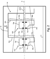
- FIG. 2 is a schematic illustration of first bearing compartment 62a, second bearing compartment 62b, and fluid supply line 64.
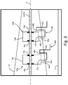
- FIG. 3 is a schematic illustration of first bearing compartment 62a and second bearing compartment 62b from FIG. 2 connected to first scavenge line 66a and second scavenge line 66b respectively.
- First bearing compartment 62a and second bearing compartment 62b are disposed within core casing 25 and can be disposed in low pressure turbine section 46, high pressure turbine section 54, and/or mid-turbine frame 58.
- First bearing compartment 62a and second bearing compartment 62b can each house and enclose one or more bearing assemblies.
- First bearing compartment 62a and second bearing compartment 62b are positioned on center axis A of gas turbine engine 20 and inner shaft 40 and/or outer shaft 50 can extend through first bearing compartment 62a and second bearing compartment 62b.
- first bearing compartment 62a includes bottom 68a, top 70a, outlet 72a, inlet 74a, and seals 76a.
- second bearing compartment 62b includes bottom 68b, top 70b, outlet 72b, inlet 74b, and seals 76b.
- Bottom 68a of first bearing compartment 62a is disposed opposite top 70a.
- top 70a of first bearing compartment 62a is disposed vertically above bottom 68a relative to ground G.
- Both inlet 74a and outlet 72a of first bearing compartment 62a are formed in bottom 68a.
- Inlet 74a is a nozzle that allows lubricating fluid, such as oil, to enter first bearing compartment 62a.
- Outlet 72a is an orifice that allows the oil to exit first bearing compartment 62a.
- Seals 76a are positioned vertically between bottom 68a and top 70a of first bearing compartment 62a.
- Seals 76a can be carbon seals that are disposed around shaft 40/50 where shaft 40/50 enters and exits first bearing compartment 62a. Seals 76a help prevent dust or debris from entering first bearing compartment 62a from outside and also help prevent oil from exiting first bearing compartment 62a into the high temperature environment of turbine section 28. Second bearing compartment 62b, bottom 68b, top 70b, outlet 72b, inlet 74b, and seals 76b are configured in a similar manner as described above with reference to first bearing compartment 62a, bottom 68a, top 70a, outlet 72a, inlet 74a, and seals 76a.
- fluid supply line 64 includes main line 78, anti-siphon line 80 attached to lubrication venting system (not shown), first supply line 82a, and second supply line 82b.
- First supply line 82a includes lower portion 84a and upper portion 86a.
- Second supply line 82b includes lower portion 84b and upper portion 86b.
- Upper portions 86a and 86b of the supply lines 82a and 82b are lubrication fluid reservoirs that fill the traps during shutdown.
- Main line 78 of fluid supply line 64 is disposed outside core casing 25 and is positioned vertically above first bearing compartment 62a and second bearing compartment 62b with respect to ground G.
- Main line 78 can be connected to a fluid tank (not shown) for supplying oil to fluid supply line 64.
- First supply line 82a extends vertically downward from main line 78, enters core casing 25, and connects to inlet 74a of first bearing compartment 62a.
- the portion of first supply line 82a that is disposed within core casing 25 is indicated in phantom in FIG. 2 .
- Second supply line 82b extends vertically downward from main line 78, enters core casing 25, and connects to inlet 74b of second bearing compartment 62b.
- the portion of second supply line 82b that is disposed within core casing 25 is indicated in phantom in FIG. 2 and can also be disposed within a vane or strut of low pressure turbine section 46, high pressure turbine section 54, or mid-turbine frame 58.
- Anti-siphon line 80 is positioned on main line 78 between first supply line 82a and second supply line 82b.
- Anti-siphon line 80 enters main line 78 from above and is configured to allow air to enter main line 78 at engine shutdown to prevent oil from being siphoned back up from first supply line 82a and second supply line 82b into main line 78.
- Anti-siphon line 80 can be connected to a breather line (not shown) as an air source.
- the air in the breather line can have a relatively high air to oil ratio and can vent to ambient pressure, i.e. the pressure of the environment outside of gas turbine engine 20.
- First supply line 82a includes lower portion 84a and upper portion 86a.
- Upper portion 86a of first supply line 82a is defined as the portion of first supply line 82a that extends vertically above bottom 68a of first bearing compartment 62a.
- Lower portion 84a of first supply line 82a is defined as the portion of first supply line 82a that is disposed vertically below bottom 68a of first bearing compartment 62a with respect to ground G.
- first supply line 82a from inlet 74a of first bearing compartment 62a to main line 78, lower portion 84a extends vertically downward from inlet 74a and bottom 68a of first bearing compartment 62a. Lower portion 84a of first supply line 82a then exits core casing 25. After exiting core casing 25, lower portion 84a of first supply line 82a then extends vertically upward to a position that is equal in vertical height with bottom 68a of first bearing compartment 62a. First supply line 82a transitions to upper portion 86a and continues from bottom 68a of first bearing compartment 62a to main line 78, main line 78 being positioned vertically above top 70a of first bearing compartment 62a. Upper portion 86a is substantially larger in volume and length than lower portion 84a so that upper portion 86a contains enough oil at engine shutdown to fill all of lower portion 84a plus portions of first scavenge line 66a (shown in FIG. 3 ).
- second supply line 82b includes lower portion 84b and upper portion 86b. As shown in FIG. 2 , lower portion 84b and upper portion 86b of second supply line 82b are configured in the same manner as lower portion 84a and upper portion 86a of first supply line 82a respectively.
- first scavenge line 66a is connected to outlet 72a of first bearing compartment 62a and second scavenge line 66b is connected to outlet 72b of second bearing compartment 62b.
- First scavenge line 66a includes fluid trap 88a formed by first portion 90a and second portion 92a of first scavenge line 66a.
- Second scavenge line 66b includes fluid trap 88b formed by first portion 90b and second portion 92b of second scavenge line 66b.
- Second scavenge line 66b, fluid trap 88b, first portion 90b, and second portion 92b are all configured in a manner similar to first scavenge line 66a, fluid trap 88a, first portion 90a, and second portion 92a respectively, which manner is described below.
- First portion 90a of first scavenge line 66a extends vertically downward from outlet 72a and bottom 68a of first bearing compartment 62a and exits core casing 25.
- the part of first portion 90a of first scavenge line 66a that is disposed inside core casing 25 is indicated in phantom in FIG. 3 and can be disposed within a vane or strut of low pressure turbine section 46, high pressure turbine section 54, or mid-turbine frame 58.
- first portion 90a transitions into second portion 92a of first scavenge line 66a.
- Second portion 92a of first scavenge line 66a extends vertically upward outside of core casing 25 to a position disposed vertically between a height of bottom 68a of first bearing compartment 62a and a height of seals 76a.
- First scavenge line 66a extends radially downward downstream from second portion 92a, as shown in FIG. 3 .
- First portion 90a and second portion 92a together form fluid trap 88a.
- Fluid trap 88a has an inside volume that is equal to or less than the inside volume of upper portion 86a of first supply line 82a.
- upper portion 86a of first supply line 82a includes an inside volume that is greater than the combined inside volumes of fluid trap 88a and lower portion 84a of first supply line 82a.
- the oil entering first scavenge line 88a can contain a considerable amount of air mixed with the oil, which will bubble out to high points in the scavenge line 88a and the bearing compartment 62a.
- the inside volume of fluid trap 88a can be decreased to help ensure that first supply line 82a is able to deliver enough oil to fill fluid trap 88a even when the oil in first scavenge line 88a is mixed with air.
- the inside volume of fluid trap 88a can be decreased by axially aligning fluid trap 88a with outlet 72a of first bearing compartment 62a relative center axis A of gas turbine engine 20.
- Axially aligning fluid trap 88a with outlet 72a of first bearing compartment 62a moves fluid trap 88a closer to first bearing compartment 62a thereby decreasing the length and inside volume of fluid trap 88a without decreasing the cross-sectional flow area of fluid trap 88a.
- first bearing compartment 62a with first supply line 82a and first scavenge line 66a.
- First scavenge line 66a includes fluid trap 88a with a height disposed vertically between bottom 68a and seals 76a of first bearing compartment 62a.
- First supply line 82a provides enough oil to fluid trap 88a to keep the portions of first supply line 82a and first scavenge line 66a disposed inside core casing 25 full of oil at engine shutdown.
- first supply line 82a and first scavenge line 66a By keeping the portions of first supply line 82a and first scavenge line 66a disposed inside core casing 25 full of oil at engine shutdown, the soak back heat of the gas turbine engine at shutdown is insufficient to cause coking inside first supply line 82a and first scavenge line 66a.
- Protecting first supply line 82a and first scavenge line 66a against coking helps keep these passages clear so that first bearing compartment 62a receives a steady supply of oil during engine operation to keep the bearings therein cool and lubricated.
- the height of fluid trap 88a keeps oil from flooding first bearing compartment 62a and leaking out through seals 76a into the hot environment of turbine section 28.
- a gas turbine engine in one embodiment, includes a bearing compartment with a bottom disposed opposite a top. An outlet is formed in the bottom of the bearing compartment. A seal is positioned between the bottom of the bearing compartment and the top of the bearing compartment. A scavenge line is connected to the outlet. The scavenge line forms a fluid trap that extends in a first direction from the outlet and the bottom of the bearing compartment and then extends in a second direction to a position disposed vertically between the bottom of the bearing compartment and the seal.
- the gas turbine engine of the preceding paragraph can optionally include, additionally and/or alternatively, any one or more of the following features, configurations and/or additional components:
- a gas turbine engine in another embodiment, includes a core casing and a bearing compartment disposed within the core casing.
- the bearing compartment includes a bottom disposed vertically opposite a top and an outlet formed in the bottom of the bearing compartment.
- a seal is positioned vertically between the bottom of the bearing compartment and the top of the bearing compartment.
- a scavenge line is connected to the outlet. The scavenge line forms a fluid trap that first extends vertically downward from the outlet and the bottom of the bearing compartment and exits the core casing, and then extends upward to a position disposed vertically between the bottom of the bearing compartment and the seal.
- the gas turbine engine of the preceding paragraph can optionally include, additionally and/or alternatively, any one or more of the following features, configurations and/or additional components:
- any relative terms or terms of degree used herein such as “substantially”, “essentially”, “generally”, “approximately”, and the like, should be interpreted in accordance with and subject to any applicable definitions or limits expressly stated herein. In all instances, any relative terms or terms of degree used herein should be interpreted to broadly encompass any relevant disclosed embodiments as well as such ranges or variations as would be understood by a person of ordinary skill in the art in view of the entirety of the present disclosure, such as to encompass ordinary manufacturing tolerance variations, incidental alignment variations, transitory vibrations and sway movements, temporary alignment or shape variations induced by operational conditions, and the like.
- FIG. 2 shows first supply line 82a and second supply line 82b both connecting to main line 78
- first supply line 82a and second supply line 82b can each be connected to a different main line and different fluid tank respectively.
- many modifications may be made to adapt a particular situation or material to the teachings of the invention without departing from the essential scope thereof. Therefore, it is intended that the invention not be limited to the particular embodiment(s) disclosed, but that the invention will include all embodiments falling within the scope of the appended claims.
Landscapes
- Engineering & Computer Science (AREA)
- Mechanical Engineering (AREA)
- General Engineering & Computer Science (AREA)
- Chemical & Material Sciences (AREA)
- Combustion & Propulsion (AREA)
- Turbine Rotor Nozzle Sealing (AREA)
- Rolling Contact Bearings (AREA)
- Sealing Of Bearings (AREA)
Abstract
Description
- The present disclosure relates to lubrication systems for gas turbine engines and more particularly to a solution for overcoming oil coking in the lubrication system.
- Every gas turbine engine includes bearings to support the rotary shafts of the engine. The bearings are typically housed in bearing compartments that are connected to a lubrication system. The lubrication system provides lubricant, such as oil, to the bearing compartment through a supply line to lubricate and cool the bearings. The lubrication system also recovers the oil from the bearing compartment through a scavenge line and sends the oil through a filter and heat exchanger before cycling the oil back to the bearing compartment.
- At shutdown of the gas turbine engine, the lubrication system ceases to circulate oil to the bearing compartment and the oil, now without pumping pressure, drains out of both the supply line and the scavenge line and back to a sump or nose point in the lubrication system. With the lubrication system inactive and no longer dissipating heat from the bearing compartment, heat produced by the gas turbine engine just prior to shutdown can "soak back" into both the bearing compartment and the supply and scavenge lines and can excessively elevate the temperature of these engine components. The elevated temperatures caused by the heat soak back can cause oil mist or oil film located in the supply line and the scavenge line to react with air and form coke deposits on the inside surfaces of the supply line and the scavenge line. Over time, these coke deposits can accumulate and clog the supply line and the scavenge line and starve the bearing compartment of oil. Without an adequate supply of oil, the bearings in the bearing compartment can fail and result in engine-wide failure of the gas turbine engine.
- In one aspect of the disclosure, a gas turbine engine includes a bearing compartment with a bottom disposed opposite a top. An outlet is formed in the bottom of the bearing compartment. A seal is positioned between the bottom of the bearing compartment and the top of the bearing compartment. A scavenge line is connected to the outlet. The scavenge line forms a fluid trap that extends in a first direction from the outlet and the bottom of the bearing compartment and then extends in a second direction to a position disposed vertically between the bottom of the bearing compartment and the seal.
- In another aspect of the disclosure, a gas turbine engine includes a core casing and a bearing compartment disposed within the core casing. The bearing compartment includes a bottom disposed vertically opposite a top and an outlet formed in the bottom of the bearing compartment. A seal is positioned vertically between the bottom of the bearing compartment and the top of the bearing compartment. A scavenge line is connected to the outlet. The scavenge line forms a fluid trap that first extends vertically downward from the outlet and the bottom of the bearing compartment and exits the core casing, and then extends upward to a position disposed vertically between the bottom of the bearing compartment and the seal.
- Persons of ordinary skill in the art will recognize that other aspects and embodiments of the present invention are possible in view of the entirety of the present disclosure, including the accompanying figures.
-
-
FIG. 1 is a partial cross-sectional view of a gas turbine engine. -
FIG. 2 is a schematic illustration of a fluid supply system for a first bearing compartment and a second bearing compartment in a turbine section of the gas turbine engine fromFIG. 1 . -
FIG. 3 is a schematic illustration of a fluid scavenge system for the first bearing compartment and the second bearing compartment fromFIG. 2 . - While the above-identified drawing figures set forth one or more embodiments of the invention, other embodiments are also contemplated. In all cases, this disclosure presents the invention by way of representation and not limitation. It should be understood that numerous other modifications and embodiments can be devised by those skilled in the art, which fall within the scope and spirit of the principles of the invention. The figures may not be drawn to scale, and applications and embodiments of the present invention may include features and components not specifically shown in the drawings. Like reference numerals identify similar structural elements.
- The disclosure relates to a bearing compartment in a gas turbine engine with an outlet and a scavenge line for draining lubricating fluid from the bearing compartment. The scavenge line includes a fluid trap attached to the outlet that extends downward and then extends upward to a position disposed vertically between the outlet and a shaft seal of the bearing compartment. A supply line is connected to the bearing compartment and extends above the bearing compartment to form a fluid reservoir with enough volume to fill the fluid traps in the supply and scavenge lines upon engine shutdown. At engine shutdown, the lubricating fluid in the fluid reservoir flows into the bearing compartment and into the scavenge fluid trap, filling the fluid traps with lubricating fluid without flooding the bearing compartment to the level of the shaft seal. Because the fluid traps are filled with lubricating fluid, the residual heat of the engine at shutdown is unable to cause coking in the supply and scavenge lines of the bearing compartment. The fluid reservoir and fluid traps are discussed below with reference to the figures.
-
FIG. 1 is a quarter-sectional view that schematically illustrates examplegas turbine engine 20 that includesfan section 22,compressor section 24,combustor section 26 andturbine section 28. Alternative engines might include an augmenter section (not shown) among other systems or features.Fan section 22 drives air along bypass flowpath B whilecompressor section 24 draws air in along core flowpath C where air is compressed and communicated tocombustor section 26. Incombustor section 26, air is mixed with fuel and ignited to generate a high pressure exhaust gas stream that expands throughturbine section 28 where energy is extracted and utilized to drivefan section 22 andcompressor section 24.Core casing 25 is disposed aroundcompressor section 24,combustor section 26 andturbine section 28 and separates these sections from bypass flowpath B. - Although the disclosed non-limiting embodiment depicts a turbofan gas turbine engine, it should be understood that the concepts described herein are not limited to use with turbofans as the teachings may be applied to other types of turbine engines; for example, an industrial gas turbine; a reverse-flow gas turbine engine; and a turbine engine including a three-spool architecture in which three spools concentrically rotate about a common axis and where a low spool enables a low pressure turbine to drive a fan via a gearbox, an intermediate spool that enables an intermediate pressure turbine to drive a first compressor of the compressor section, and a high spool that enables a high pressure turbine to drive a high pressure compressor of the compressor section.
- The example
gas turbine engine 20 generally includeslow speed spool 30 andhigh speed spool 32 mounted for rotation about center axis A ofgas turbine engine 20 relative to enginestatic structure 36 viaseveral bearing systems 38. It should be understood thatvarious bearing systems 38 at various locations may alternatively or additionally be provided. -
Low speed spool 30 generally includesinner shaft 40 that connectsfan 42 and low pressure (or first)compressor section 44 to low pressure (or first)turbine section 46.Inner shaft 40 drivesfan 42 through a speed change device, such as gearedarchitecture 48, to drivefan 42 at a lower speed thanlow speed spool 30. High-speed spool 32 includesouter shaft 50 that interconnects high pressure (or second)compressor section 52 and high pressure (or second)turbine section 54.Inner shaft 40 andouter shaft 50 are concentric and rotate viabearing systems 38 about center axis A. - Combustor 56 is arranged between
high pressure compressor 52 and highpressure turbine section 54. In one example, highpressure turbine section 54 includes at least two stages to provide double stage highpressure turbine section 54. In another example, highpressure turbine section 54 includes only a single stage. As used herein, a "high pressure" compressor or turbine experiences a higher pressure than a corresponding "low pressure" compressor or turbine. -
Mid-turbine frame 58 of enginestatic structure 36 can be arranged generally between highpressure turbine section 54 andlow pressure turbine 46.Mid-turbine frame 58 further supports bearingsystems 38 inturbine section 28 as well as setting airflow entering thelow pressure turbine 46. - The gas flow in core flowpath C is compressed first by
low pressure compressor 44 and then byhigh pressure compressor 52 mixed with fuel and ignited incombustor 56 to produce high pressure exhaust gases that are then expanded through highpressure turbine section 54 andlow pressure turbine 46.Mid-turbine frame 58 includesvanes 60, which are in the core flowpath and function as an inlet guide vane forlow pressure turbine 46. -
FIGS. 2 and3 will be discussed concurrently.FIG. 2 is a schematic illustration offirst bearing compartment 62a,second bearing compartment 62b, andfluid supply line 64.FIG. 3 is a schematic illustration offirst bearing compartment 62a andsecond bearing compartment 62b fromFIG. 2 connected tofirst scavenge line 66a andsecond scavenge line 66b respectively. First bearingcompartment 62a andsecond bearing compartment 62b are disposed withincore casing 25 and can be disposed in lowpressure turbine section 46, highpressure turbine section 54, and/ormid-turbine frame 58. First bearingcompartment 62a and second bearingcompartment 62b can each house and enclose one or more bearing assemblies. First bearingcompartment 62a andsecond bearing compartment 62b are positioned on center axis A ofgas turbine engine 20 andinner shaft 40 and/orouter shaft 50 can extend throughfirst bearing compartment 62a andsecond bearing compartment 62b. As shown inFIGS 2 and3 ,first bearing compartment 62a includes bottom 68a, top 70a,outlet 72a,inlet 74a, and seals 76a. Similar tofirst bearing compartment 62a,second bearing compartment 62b includes bottom 68b, top 70b,outlet 72b,inlet 74b, and seals 76b. - Bottom 68a of
first bearing compartment 62a is disposed opposite top 70a. Whengas turbine engine 20 is attached to an aircraft and that aircraft is parked on ground G, top 70a offirst bearing compartment 62a is disposed vertically abovebottom 68a relative to ground G. Bothinlet 74a andoutlet 72a offirst bearing compartment 62a are formed inbottom 68a.Inlet 74a is a nozzle that allows lubricating fluid, such as oil, to enterfirst bearing compartment 62a.Outlet 72a is an orifice that allows the oil to exitfirst bearing compartment 62a.Seals 76a are positioned vertically betweenbottom 68a and top 70a offirst bearing compartment 62a.Seals 76a can be carbon seals that are disposed aroundshaft 40/50 whereshaft 40/50 enters and exitsfirst bearing compartment 62a.Seals 76a help prevent dust or debris from enteringfirst bearing compartment 62a from outside and also help prevent oil from exitingfirst bearing compartment 62a into the high temperature environment ofturbine section 28.Second bearing compartment 62b, bottom 68b, top 70b,outlet 72b,inlet 74b, and seals 76b are configured in a similar manner as described above with reference tofirst bearing compartment 62a, bottom 68a, top 70a,outlet 72a,inlet 74a, and seals 76a. - As shown in
FIG. 2 ,fluid supply line 64 includesmain line 78,anti-siphon line 80 attached to lubrication venting system (not shown),first supply line 82a, andsecond supply line 82b.First supply line 82a includeslower portion 84a andupper portion 86a.Second supply line 82b includeslower portion 84b andupper portion 86b.Upper portions supply lines -
Main line 78 offluid supply line 64 is disposed outsidecore casing 25 and is positioned vertically abovefirst bearing compartment 62a andsecond bearing compartment 62b with respect to groundG. Main line 78 can be connected to a fluid tank (not shown) for supplying oil tofluid supply line 64.First supply line 82a extends vertically downward frommain line 78, enterscore casing 25, and connects toinlet 74a offirst bearing compartment 62a. The portion offirst supply line 82a that is disposed withincore casing 25 is indicated in phantom inFIG. 2 . The portion offirst supply line 82a that is disposed withincore casing 25 and indicated in phantom inFIG. 2 can be disposed within a vane or strut of lowpressure turbine section 46, highpressure turbine section 54, ormid-turbine frame 58.Second supply line 82b extends vertically downward frommain line 78, enterscore casing 25, and connects toinlet 74b ofsecond bearing compartment 62b. The portion ofsecond supply line 82b that is disposed withincore casing 25 is indicated in phantom inFIG. 2 and can also be disposed within a vane or strut of lowpressure turbine section 46, highpressure turbine section 54, ormid-turbine frame 58.Anti-siphon line 80 is positioned onmain line 78 betweenfirst supply line 82a andsecond supply line 82b.Anti-siphon line 80 entersmain line 78 from above and is configured to allow air to entermain line 78 at engine shutdown to prevent oil from being siphoned back up fromfirst supply line 82a andsecond supply line 82b intomain line 78.Anti-siphon line 80 can be connected to a breather line (not shown) as an air source. The air in the breather line can have a relatively high air to oil ratio and can vent to ambient pressure, i.e. the pressure of the environment outside ofgas turbine engine 20. -
First supply line 82a includeslower portion 84a andupper portion 86a.Upper portion 86a offirst supply line 82a is defined as the portion offirst supply line 82a that extends vertically above bottom 68a offirst bearing compartment 62a.Lower portion 84a offirst supply line 82a is defined as the portion offirst supply line 82a that is disposed vertically below bottom 68a offirst bearing compartment 62a with respect to ground G. - Following
first supply line 82a frominlet 74a offirst bearing compartment 62a tomain line 78,lower portion 84a extends vertically downward frominlet 74a and bottom 68a offirst bearing compartment 62a.Lower portion 84a offirst supply line 82a then exitscore casing 25. After exitingcore casing 25,lower portion 84a offirst supply line 82a then extends vertically upward to a position that is equal in vertical height with bottom 68a offirst bearing compartment 62a.First supply line 82a transitions toupper portion 86a and continues from bottom 68a offirst bearing compartment 62a tomain line 78,main line 78 being positioned vertically above top 70a offirst bearing compartment 62a.Upper portion 86a is substantially larger in volume and length thanlower portion 84a so thatupper portion 86a contains enough oil at engine shutdown to fill all oflower portion 84a plus portions offirst scavenge line 66a (shown inFIG. 3 ). - Similar to
first supply line 82a,second supply line 82b includeslower portion 84b andupper portion 86b. As shown inFIG. 2 ,lower portion 84b andupper portion 86b ofsecond supply line 82b are configured in the same manner aslower portion 84a andupper portion 86a offirst supply line 82a respectively. - As shown in
FIG. 3 ,first scavenge line 66a is connected tooutlet 72a offirst bearing compartment 62a andsecond scavenge line 66b is connected tooutlet 72b ofsecond bearing compartment 62b. First scavengeline 66a includesfluid trap 88a formed byfirst portion 90a andsecond portion 92a offirst scavenge line 66a.Second scavenge line 66b includesfluid trap 88b formed byfirst portion 90b andsecond portion 92b ofsecond scavenge line 66b. -
Second scavenge line 66b,fluid trap 88b,first portion 90b, andsecond portion 92b are all configured in a manner similar tofirst scavenge line 66a,fluid trap 88a,first portion 90a, andsecond portion 92a respectively, which manner is described below. -
First portion 90a offirst scavenge line 66a extends vertically downward fromoutlet 72a and bottom 68a offirst bearing compartment 62a and exitscore casing 25. The part offirst portion 90a offirst scavenge line 66a that is disposed insidecore casing 25 is indicated in phantom inFIG. 3 and can be disposed within a vane or strut of lowpressure turbine section 46, highpressure turbine section 54, ormid-turbine frame 58. After exitingcore casing 25,first portion 90a transitions intosecond portion 92a offirst scavenge line 66a.Second portion 92a offirst scavenge line 66a extends vertically upward outside ofcore casing 25 to a position disposed vertically between a height of bottom 68a offirst bearing compartment 62a and a height ofseals 76a. First scavengeline 66a extends radially downward downstream fromsecond portion 92a, as shown inFIG. 3 .First portion 90a andsecond portion 92a together formfluid trap 88a.Fluid trap 88a has an inside volume that is equal to or less than the inside volume ofupper portion 86a offirst supply line 82a. Preferably,upper portion 86a offirst supply line 82a includes an inside volume that is greater than the combined inside volumes offluid trap 88a andlower portion 84a offirst supply line 82a. - At engine shutdown, the volume of oil disposed in
upper portion 86a offirst supply line 82a flows downward under the influence of gravity intolower portion 84a offirst supply line 82a. Becauseupper portion 86a is higher thaninlet 74a to bearingcompartment 62a and theanti-siphon line 80 allows air inmain line 78, oil flows intofirst bearing compartment 62a throughinlet 74a without emptyinglower portion 84a offirst supply line 82a. From there, the oil flows intooutlet 72a and intofirst scavenge line 66a. Sinceupper portion 86a has a larger inside volume thanlower portion 84a andfluid trap 88a combined, enough oil flows downward fromupper portion 86a to fill bothlower portion 84a offirst supply line 82a andfluid trap 88a offirst scavenge line 66a. Withlower portion 84a offirst supply line 82a andfluid trap 88a offirst scavenge line 66a filled with oil at engine shutdown, the parts oflower portion 84a and the parts offluid trap 88a disposed insidecore casing 25 are better protected against coking because passages filled with oil require higher temperatures for coking to occur than passages that mostly contain air and small amounts of oil in the form of droplets or film. - While the oil fills
lower portion 84a andfluid trap 88a, the oil flowing fromupper portion 86a offirst supply line 82a does not fillfirst bearing compartment 62a enough to reachseals 76a because the vertical height offluid trap 88a is disposed vertically belowseals 76a. Becausefluid trap 88a keeps oil from reachingseals 76a, oil is unable to leak out offirst bearing compartment 62a throughseals 76a into the hot environment ofturbine section 28 at engine shutdown. - The oil entering
first scavenge line 88a can contain a considerable amount of air mixed with the oil, which will bubble out to high points in thescavenge line 88a and thebearing compartment 62a. The inside volume offluid trap 88a can be decreased to help ensure thatfirst supply line 82a is able to deliver enough oil to fillfluid trap 88a even when the oil infirst scavenge line 88a is mixed with air. The inside volume offluid trap 88a can be decreased by axially aligningfluid trap 88a withoutlet 72a offirst bearing compartment 62a relative center axis A ofgas turbine engine 20. Axially aligningfluid trap 88a withoutlet 72a offirst bearing compartment 62a movesfluid trap 88a closer tofirst bearing compartment 62a thereby decreasing the length and inside volume offluid trap 88a without decreasing the cross-sectional flow area offluid trap 88a. - In view of the foregoing description, it will be recognized that the present disclosure provides numerous advantages and benefits. For example, the present disclosure provides
first bearing compartment 62a withfirst supply line 82a andfirst scavenge line 66a. First scavengeline 66a includesfluid trap 88a with a height disposed vertically betweenbottom 68a and seals 76a offirst bearing compartment 62a.First supply line 82a provides enough oil tofluid trap 88a to keep the portions offirst supply line 82a andfirst scavenge line 66a disposed insidecore casing 25 full of oil at engine shutdown. By keeping the portions offirst supply line 82a andfirst scavenge line 66a disposed insidecore casing 25 full of oil at engine shutdown, the soak back heat of the gas turbine engine at shutdown is insufficient to cause coking insidefirst supply line 82a andfirst scavenge line 66a. Protectingfirst supply line 82a andfirst scavenge line 66a against coking helps keep these passages clear so thatfirst bearing compartment 62a receives a steady supply of oil during engine operation to keep the bearings therein cool and lubricated. Furthermore, the height offluid trap 88a keeps oil from flooding first bearingcompartment 62a and leaking out throughseals 76a into the hot environment ofturbine section 28. - The following are non-exclusive descriptions of possible embodiments of the present invention.
- In one embodiment, a gas turbine engine includes a bearing compartment with a bottom disposed opposite a top. An outlet is formed in the bottom of the bearing compartment. A seal is positioned between the bottom of the bearing compartment and the top of the bearing compartment. A scavenge line is connected to the outlet. The scavenge line forms a fluid trap that extends in a first direction from the outlet and the bottom of the bearing compartment and then extends in a second direction to a position disposed vertically between the bottom of the bearing compartment and the seal.
- The gas turbine engine of the preceding paragraph can optionally include, additionally and/or alternatively, any one or more of the following features, configurations and/or additional components:
- the bearing compartment is disposed within a core casing of the gas turbine engine;
- the fluid trap extends vertically downward from the outlet and the bottom of the bearing compartment and then extends upward to the position disposed vertically between the bottom of the bearing compartment and the seal;
- the scavenge line first extends vertically downward from the outlet and the bottom of the bearing compartment and exits the core casing, and then extends upward outside of the core casing to the position disposed vertically between the bottom of the bearing compartment and the seal;
- the bearing compartment comprises an inlet and the gas turbine engine further comprises a fluid supply line connected to the inlet;
- a portion of the fluid supply line extends vertically upward;
- the portion of the fluid supply line that extends vertically upward comprises a volume sufficient to contain enough lubricating fluid to replace air that bubbles out of lubricating fluid disposed inside the fluid trap of the scavenge line.
- the bearing compartment comprises an inlet formed in the bottom of the bearing compartment and the gas turbine engine further comprises a fluid supply line connected to the inlet, wherein the fluid supply line first extends vertically downward from the inlet and the bottom of the bearing compartment and exits the core casing, and then extends upward to a position disposed vertically above the top of the bearing compartment; and/or
- the fluid trap axially aligned with the bearing compartment relative a center axis of the gas turbine engine.
- In another embodiment, a gas turbine engine includes a core casing and a bearing compartment disposed within the core casing. The bearing compartment includes a bottom disposed vertically opposite a top and an outlet formed in the bottom of the bearing compartment. A seal is positioned vertically between the bottom of the bearing compartment and the top of the bearing compartment. A scavenge line is connected to the outlet. The scavenge line forms a fluid trap that first extends vertically downward from the outlet and the bottom of the bearing compartment and exits the core casing, and then extends upward to a position disposed vertically between the bottom of the bearing compartment and the seal.
- The gas turbine engine of the preceding paragraph can optionally include, additionally and/or alternatively, any one or more of the following features, configurations and/or additional components:
- the bearing compartment comprises an inlet formed in the bottom of the bearing compartment;
- the gas turbine engine further comprises a fluid supply line connected to the inlet;
- the fluid supply line first extends vertically downward from the inlet and the bottom of the bearing compartment and exits the core casing, and then extends vertically upward above the bottom of the bearing compartment;
- a portion of the fluid supply line that extends vertically upward above the bottom of the bearing compartment comprises a volume that is greater than or equal to a volume of the fluid trap of the scavenge line;
- an anti-siphon line is connected to the fluid supply line above the bearing compartment, wherein the anti-siphon line is configured to allow air at ambient pressure to enter the fluid supply line at engine shutdown;
- a portion of the fluid supply line that extends vertically upward above the bottom of the bearing compartment comprises a volume sufficient to contain enough lubricating fluid to replace air that bubbles out of lubricating fluid disposed inside the fluid trap of the scavenge line;
- the fluid trap is axially aligned with the outlet of the bearing compartment relative a center axis of the gas turbine engine; and/or
- the seal is a carbon seal.
- Any relative terms or terms of degree used herein, such as "substantially", "essentially", "generally", "approximately", and the like, should be interpreted in accordance with and subject to any applicable definitions or limits expressly stated herein. In all instances, any relative terms or terms of degree used herein should be interpreted to broadly encompass any relevant disclosed embodiments as well as such ranges or variations as would be understood by a person of ordinary skill in the art in view of the entirety of the present disclosure, such as to encompass ordinary manufacturing tolerance variations, incidental alignment variations, transitory vibrations and sway movements, temporary alignment or shape variations induced by operational conditions, and the like.
- While the invention has been described with reference to an exemplary embodiment(s), it will be understood by those skilled in the art that various changes may be made and equivalents may be substituted for elements thereof without departing from the scope of the invention. For example, while
FIG. 2 showsfirst supply line 82a andsecond supply line 82b both connecting tomain line 78,first supply line 82a andsecond supply line 82b can each be connected to a different main line and different fluid tank respectively. In addition, many modifications may be made to adapt a particular situation or material to the teachings of the invention without departing from the essential scope thereof. Therefore, it is intended that the invention not be limited to the particular embodiment(s) disclosed, but that the invention will include all embodiments falling within the scope of the appended claims.
Claims (15)
- A gas turbine engine (20) comprises:a bearing compartment (62a,62b), wherein the bearing compartment (62a,62b) comprises:a bottom (68a,68b) disposed opposite a top (70a,70b);an outlet (72a,72b) formed in the bottom (68a,68b) of the bearing compartment (62a,62b); anda seal (76a,76b) positioned between the bottom (68a,68b) of the bearing compartment (62a,62b) and the top (70a,70b) of the bearing compartment (62a,62b); anda scavenge line (66a,66b) connected to the outlet (72a,72b), wherein the scavenge line (66a,66b) forms a fluid trap (88a,88b) that extends in a first direction from the outlet (72a,72b) and the bottom (68a,68b) of the bearing compartment (62a,62b) and then extends in a second direction to a position disposed vertically between the bottom (68a,68b) of the bearing compartment (62a,62b) and the seal (76a,76b).
- The gas turbine engine (20) of claim 1, wherein the bearing compartment (62a,62b) is disposed within a core casing of the gas turbine engine (20).
- The gas turbine engine (20) of claim 2, wherein the fluid trap (88a,88b) extends vertically downward from the outlet (72a,72b) and the bottom (68a,68b) of the bearing compartment (62a,62b) and then extends upward to the position disposed vertically between the bottom (68a,68b) of the bearing compartment (62a,62b) and the seal (76a,76b).
- The gas turbine engine (20) of claim 2 or 3, wherein the scavenge line (66a,66b) first extends vertically downward from the outlet (72a,72b) and the bottom (68a,68b) of the bearing compartment (62a,62b) and exits the core casing, and then extends upward outside of the core casing to the position disposed vertically between the bottom (68a,68b) of the bearing compartment (62a,62b) and the seal (76a,76b).
- The gas turbine engine (20) of any preceding claim, wherein the bearing compartment (62a,62b) comprises an inlet (74a,74b) and the gas turbine engine (20) further comprises a fluid supply line (82a,82b) connected to the inlet (74a,74b).
- The gas turbine engine (20) of claim 5, wherein a portion of the fluid supply line (82a,82b) extends vertically upward.
- The gas turbine engine (20) of any of claims 1 to 4, wherein the bearing compartment (62a,62b) comprises an inlet (74a,74b) formed in the bottom (68a,68b) of the bearing compartment (62a,62b) and the gas turbine engine (20) further comprises a fluid supply line (82a,82b) connected to the inlet (74a,74b), wherein the fluid supply line (82a,82b) first extends vertically downward from the inlet (74a,74b) and the bottom (68a,68b) of the bearing compartment (62a,62b) and exits the core casing, and then extends upward to a position disposed vertically above the top (70a,70b) of the bearing compartment (62a,62b).
- The gas turbine engine (20) of claim 6 or 7, wherein the portion of the fluid supply line (82a,82b) that extends vertically upward comprises a volume sufficient to contain enough lubricating fluid to replace air that bubbles out of lubricating fluid disposed inside the fluid trap (88a,88b) of the scavenge line (66a,66b).
- The gas turbine engine (20) of any of claims 1 to 4, wherein the bearing compartment (62a,62b) comprises an inlet (74a,74b) formed in the bottom (68a,68b) of the bearing compartment (62a,62b).
- The gas turbine engine (20) of claim 9, wherein the gas turbine engine (20) further comprises a fluid supply line (82a,82b) connected to the inlet (74a,74b).
- The gas turbine engine (20) of claim 10, wherein the fluid supply line (82a,82b) first extends vertically downward from the inlet (74a,74b) and the bottom (68a,68b) of the bearing compartment (62a,62b) and exits the core casing, and then extends vertically upward above the bottom (68a,68b) of the bearing compartment (62a,62b).
- The gas turbine engine (20) of any of claims 5 to 8, 10 or 11, wherein an anti-siphon line (80) is connected to the fluid supply line (82a,82b) above the bearing compartment (62a,62b), wherein the anti-siphon line (80) is configured to allow air at ambient pressure to enter the fluid supply line (82a,82b) at engine shutdown.
- The gas turbine engine (20) of any of claims 5 to 8 or 10 to 12, wherein a portion of the fluid supply line (82a,82b) that extends vertically upward above the bottom (68a,68b) of the bearing compartment (62a,62b) comprises a volume that is greater than or equal to a volume of the fluid trap (88a,88b) of the scavenge line (66a,66b).
- The gas turbine engine (20) of any preceding claim, wherein the fluid trap (88a,88b) is axially aligned with the outlet (72a,72b) of the bearing compartment (62a,62b) relative a center axis (A) of the gas turbine engine (20).
- The gas turbine engine (20) of any preceding claim, wherein the seal (76a,76b) is a carbon seal.
Applications Claiming Priority (1)
| Application Number | Priority Date | Filing Date | Title |
|---|---|---|---|
| US15/170,221 US10287916B2 (en) | 2016-06-01 | 2016-06-01 | Internal tube oil coke prevention geometry |
Publications (2)
| Publication Number | Publication Date |
|---|---|
| EP3255255A1 true EP3255255A1 (en) | 2017-12-13 |
| EP3255255B1 EP3255255B1 (en) | 2021-07-07 |
Family
ID=58873665
Family Applications (1)
| Application Number | Title | Priority Date | Filing Date |
|---|---|---|---|
| EP17173426.2A Active EP3255255B1 (en) | 2016-06-01 | 2017-05-30 | Gas turbine engine with lubricated shaft bearing compartment |
Country Status (2)
| Country | Link |
|---|---|
| US (1) | US10287916B2 (en) |
| EP (1) | EP3255255B1 (en) |
Cited By (1)
| Publication number | Priority date | Publication date | Assignee | Title |
|---|---|---|---|---|
| EP3396120A3 (en) * | 2017-04-24 | 2018-12-19 | United Technologies Corporation | Method and system to ensure full oil tubes after gas turbine engine shutdown |
Families Citing this family (3)
| Publication number | Priority date | Publication date | Assignee | Title |
|---|---|---|---|---|
| CN119712254B (en) * | 2023-09-27 | 2025-11-25 | 中国航发商用航空发动机有限责任公司 | Oil return lines, gas turbine engines, and lubricating oil return methods |
| US12352179B1 (en) | 2024-07-24 | 2025-07-08 | General Electric Company | Turbine engine including a lubrication system |
| US12595749B1 (en) * | 2024-11-21 | 2026-04-07 | Pratt & Whitney Canada Corp. | Oil system for aircraft engine having features to prevent drainage of component |
Citations (4)
| Publication number | Priority date | Publication date | Assignee | Title |
|---|---|---|---|---|
| EP1731719A1 (en) * | 2005-06-10 | 2006-12-13 | Rolls-Royce plc | Lubrication arrangement for bearings |
| FR2936273A1 (en) * | 2008-09-22 | 2010-03-26 | Snecma | METHOD AND SYSTEM FOR LUBRICATING A TURBOMACHINE |
| EP2538055A2 (en) * | 2011-06-22 | 2012-12-26 | United Technologies Corporation | Oil bypass channel deaerator for a geared turbofan engine |
| US20150275761A1 (en) * | 2014-03-31 | 2015-10-01 | United Technologies Corporation | Seal assembly with cooling feature |
Family Cites Families (5)
| Publication number | Priority date | Publication date | Assignee | Title |
|---|---|---|---|---|
| US3527054A (en) * | 1969-01-23 | 1970-09-08 | Gen Electric | Pressurization of lubrication sumps in gas turbine engines |
| US8226351B2 (en) * | 2005-01-06 | 2012-07-24 | Mahindra & Mahindra Ltd. | System for providing continuous lubrication to engine turbocharger shaft and bearing arrangement |
| US8596106B2 (en) * | 2008-05-21 | 2013-12-03 | The Hong Kong Polytechnic University | Isothermal forming system for production of sheet metal parts |
| GB201109799D0 (en) * | 2011-06-13 | 2011-07-27 | Rolls Royce Plc | A bearing chamber apparatus |
| EP2789806B1 (en) * | 2013-04-10 | 2017-06-14 | Nuovo Pignone S.r.l. | Methods and systems for preventing lube oil leakage in gas turbines |
-
2016
- 2016-06-01 US US15/170,221 patent/US10287916B2/en active Active
-
2017
- 2017-05-30 EP EP17173426.2A patent/EP3255255B1/en active Active
Patent Citations (4)
| Publication number | Priority date | Publication date | Assignee | Title |
|---|---|---|---|---|
| EP1731719A1 (en) * | 2005-06-10 | 2006-12-13 | Rolls-Royce plc | Lubrication arrangement for bearings |
| FR2936273A1 (en) * | 2008-09-22 | 2010-03-26 | Snecma | METHOD AND SYSTEM FOR LUBRICATING A TURBOMACHINE |
| EP2538055A2 (en) * | 2011-06-22 | 2012-12-26 | United Technologies Corporation | Oil bypass channel deaerator for a geared turbofan engine |
| US20150275761A1 (en) * | 2014-03-31 | 2015-10-01 | United Technologies Corporation | Seal assembly with cooling feature |
Cited By (3)
| Publication number | Priority date | Publication date | Assignee | Title |
|---|---|---|---|---|
| EP3396120A3 (en) * | 2017-04-24 | 2018-12-19 | United Technologies Corporation | Method and system to ensure full oil tubes after gas turbine engine shutdown |
| US10711644B2 (en) | 2017-04-24 | 2020-07-14 | Raytheon Technologies Corporation | Method and system to ensure full oil tubes after gas turbine engine shutdown |
| US10961868B2 (en) | 2017-04-24 | 2021-03-30 | Raytheon Technologies Corporation | Method and system to ensure full oil tubes after gas turbine engine shutdown |
Also Published As
| Publication number | Publication date |
|---|---|
| US20170350274A1 (en) | 2017-12-07 |
| US10287916B2 (en) | 2019-05-14 |
| EP3255255B1 (en) | 2021-07-07 |
Similar Documents
| Publication | Publication Date | Title |
|---|---|---|
| EP3396120B1 (en) | Method and system to ensure full oil tubes after gas turbine engine shutdown | |
| US12018574B2 (en) | Geared gas turbine engine with oil deaerator and air removal | |
| EP2898202B1 (en) | Lubrication system having porous feature | |
| US9995177B2 (en) | Self cleaning debris filter for fan drive gear system | |
| EP3255255B1 (en) | Gas turbine engine with lubricated shaft bearing compartment | |
| EP2809908B1 (en) | Mid-turbine frame buffer system | |
| US9062611B2 (en) | Split accessory drive system | |
| US8985278B2 (en) | Lubrication system having segmented anti-backflow feature | |
| US20180195413A1 (en) | Gas Turbine Engine Oil Tank with Integrated Packaging Configuration | |
| EP3699413B1 (en) | Fan drive gear system manifold radial tube filters | |
| EP3812603B1 (en) | Oil drainback assembly for a bearing compartment of a gas turbine engine | |
| EP3112627B1 (en) | Negative-g oil system for geared turbofan engines | |
| EP3102807A2 (en) | Auxiliary oil system for geared gas turbine engine | |
| WO2015147949A2 (en) | Auxiliary oil system for geared gas turbine engine | |
| EP3239545B1 (en) | Integrated oil supply tube and check valve |
Legal Events
| Date | Code | Title | Description |
|---|---|---|---|
| PUAI | Public reference made under article 153(3) epc to a published international application that has entered the european phase |
Free format text: ORIGINAL CODE: 0009012 |
|
| STAA | Information on the status of an ep patent application or granted ep patent |
Free format text: STATUS: THE APPLICATION HAS BEEN PUBLISHED |
|
| AK | Designated contracting states |
Kind code of ref document: A1 Designated state(s): AL AT BE BG CH CY CZ DE DK EE ES FI FR GB GR HR HU IE IS IT LI LT LU LV MC MK MT NL NO PL PT RO RS SE SI SK SM TR |
|
| AX | Request for extension of the european patent |
Extension state: BA ME |
|
| STAA | Information on the status of an ep patent application or granted ep patent |
Free format text: STATUS: REQUEST FOR EXAMINATION WAS MADE |
|
| 17P | Request for examination filed |
Effective date: 20180613 |
|
| RBV | Designated contracting states (corrected) |
Designated state(s): AL AT BE BG CH CY CZ DE DK EE ES FI FR GB GR HR HU IE IS IT LI LT LU LV MC MK MT NL NO PL PT RO RS SE SI SK SM TR |
|
| GRAP | Despatch of communication of intention to grant a patent |
Free format text: ORIGINAL CODE: EPIDOSNIGR1 |
|
| STAA | Information on the status of an ep patent application or granted ep patent |
Free format text: STATUS: GRANT OF PATENT IS INTENDED |
|
| INTG | Intention to grant announced |
Effective date: 20210121 |
|
| RAP1 | Party data changed (applicant data changed or rights of an application transferred) |
Owner name: RAYTHEON TECHNOLOGIES CORPORATION |
|
| GRAS | Grant fee paid |
Free format text: ORIGINAL CODE: EPIDOSNIGR3 |
|
| GRAA | (expected) grant |
Free format text: ORIGINAL CODE: 0009210 |
|
| STAA | Information on the status of an ep patent application or granted ep patent |
Free format text: STATUS: THE PATENT HAS BEEN GRANTED |
|
| AK | Designated contracting states |
Kind code of ref document: B1 Designated state(s): AL AT BE BG CH CY CZ DE DK EE ES FI FR GB GR HR HU IE IS IT LI LT LU LV MC MK MT NL NO PL PT RO RS SE SI SK SM TR |
|
| REG | Reference to a national code |
Ref country code: GB Ref legal event code: FG4D |
|
| REG | Reference to a national code |
Ref country code: AT Ref legal event code: REF Ref document number: 1408784 Country of ref document: AT Kind code of ref document: T Effective date: 20210715 |
|
| REG | Reference to a national code |
Ref country code: DE Ref legal event code: R096 Ref document number: 602017041531 Country of ref document: DE |
|
| REG | Reference to a national code |
Ref country code: IE Ref legal event code: FG4D |
|
| REG | Reference to a national code |
Ref country code: LT Ref legal event code: MG9D |
|
| REG | Reference to a national code |
Ref country code: NL Ref legal event code: MP Effective date: 20210707 |
|
| REG | Reference to a national code |
Ref country code: AT Ref legal event code: MK05 Ref document number: 1408784 Country of ref document: AT Kind code of ref document: T Effective date: 20210707 |
|
| PG25 | Lapsed in a contracting state [announced via postgrant information from national office to epo] |
Ref country code: NL Free format text: LAPSE BECAUSE OF FAILURE TO SUBMIT A TRANSLATION OF THE DESCRIPTION OR TO PAY THE FEE WITHIN THE PRESCRIBED TIME-LIMIT Effective date: 20210707 Ref country code: PT Free format text: LAPSE BECAUSE OF FAILURE TO SUBMIT A TRANSLATION OF THE DESCRIPTION OR TO PAY THE FEE WITHIN THE PRESCRIBED TIME-LIMIT Effective date: 20211108 Ref country code: NO Free format text: LAPSE BECAUSE OF FAILURE TO SUBMIT A TRANSLATION OF THE DESCRIPTION OR TO PAY THE FEE WITHIN THE PRESCRIBED TIME-LIMIT Effective date: 20211007 Ref country code: HR Free format text: LAPSE BECAUSE OF FAILURE TO SUBMIT A TRANSLATION OF THE DESCRIPTION OR TO PAY THE FEE WITHIN THE PRESCRIBED TIME-LIMIT Effective date: 20210707 Ref country code: FI Free format text: LAPSE BECAUSE OF FAILURE TO SUBMIT A TRANSLATION OF THE DESCRIPTION OR TO PAY THE FEE WITHIN THE PRESCRIBED TIME-LIMIT Effective date: 20210707 Ref country code: ES Free format text: LAPSE BECAUSE OF FAILURE TO SUBMIT A TRANSLATION OF THE DESCRIPTION OR TO PAY THE FEE WITHIN THE PRESCRIBED TIME-LIMIT Effective date: 20210707 Ref country code: BG Free format text: LAPSE BECAUSE OF FAILURE TO SUBMIT A TRANSLATION OF THE DESCRIPTION OR TO PAY THE FEE WITHIN THE PRESCRIBED TIME-LIMIT Effective date: 20211007 Ref country code: AT Free format text: LAPSE BECAUSE OF FAILURE TO SUBMIT A TRANSLATION OF THE DESCRIPTION OR TO PAY THE FEE WITHIN THE PRESCRIBED TIME-LIMIT Effective date: 20210707 Ref country code: LT Free format text: LAPSE BECAUSE OF FAILURE TO SUBMIT A TRANSLATION OF THE DESCRIPTION OR TO PAY THE FEE WITHIN THE PRESCRIBED TIME-LIMIT Effective date: 20210707 Ref country code: RS Free format text: LAPSE BECAUSE OF FAILURE TO SUBMIT A TRANSLATION OF THE DESCRIPTION OR TO PAY THE FEE WITHIN THE PRESCRIBED TIME-LIMIT Effective date: 20210707 Ref country code: SE Free format text: LAPSE BECAUSE OF FAILURE TO SUBMIT A TRANSLATION OF THE DESCRIPTION OR TO PAY THE FEE WITHIN THE PRESCRIBED TIME-LIMIT Effective date: 20210707 |
|
| PG25 | Lapsed in a contracting state [announced via postgrant information from national office to epo] |
Ref country code: PL Free format text: LAPSE BECAUSE OF FAILURE TO SUBMIT A TRANSLATION OF THE DESCRIPTION OR TO PAY THE FEE WITHIN THE PRESCRIBED TIME-LIMIT Effective date: 20210707 Ref country code: LV Free format text: LAPSE BECAUSE OF FAILURE TO SUBMIT A TRANSLATION OF THE DESCRIPTION OR TO PAY THE FEE WITHIN THE PRESCRIBED TIME-LIMIT Effective date: 20210707 Ref country code: GR Free format text: LAPSE BECAUSE OF FAILURE TO SUBMIT A TRANSLATION OF THE DESCRIPTION OR TO PAY THE FEE WITHIN THE PRESCRIBED TIME-LIMIT Effective date: 20211008 |
|
| REG | Reference to a national code |
Ref country code: DE Ref legal event code: R097 Ref document number: 602017041531 Country of ref document: DE |
|
| PG25 | Lapsed in a contracting state [announced via postgrant information from national office to epo] |
Ref country code: DK Free format text: LAPSE BECAUSE OF FAILURE TO SUBMIT A TRANSLATION OF THE DESCRIPTION OR TO PAY THE FEE WITHIN THE PRESCRIBED TIME-LIMIT Effective date: 20210707 |
|
| PLBE | No opposition filed within time limit |
Free format text: ORIGINAL CODE: 0009261 |
|
| STAA | Information on the status of an ep patent application or granted ep patent |
Free format text: STATUS: NO OPPOSITION FILED WITHIN TIME LIMIT |
|
| PG25 | Lapsed in a contracting state [announced via postgrant information from national office to epo] |
Ref country code: SM Free format text: LAPSE BECAUSE OF FAILURE TO SUBMIT A TRANSLATION OF THE DESCRIPTION OR TO PAY THE FEE WITHIN THE PRESCRIBED TIME-LIMIT Effective date: 20210707 Ref country code: SK Free format text: LAPSE BECAUSE OF FAILURE TO SUBMIT A TRANSLATION OF THE DESCRIPTION OR TO PAY THE FEE WITHIN THE PRESCRIBED TIME-LIMIT Effective date: 20210707 Ref country code: RO Free format text: LAPSE BECAUSE OF FAILURE TO SUBMIT A TRANSLATION OF THE DESCRIPTION OR TO PAY THE FEE WITHIN THE PRESCRIBED TIME-LIMIT Effective date: 20210707 Ref country code: EE Free format text: LAPSE BECAUSE OF FAILURE TO SUBMIT A TRANSLATION OF THE DESCRIPTION OR TO PAY THE FEE WITHIN THE PRESCRIBED TIME-LIMIT Effective date: 20210707 Ref country code: CZ Free format text: LAPSE BECAUSE OF FAILURE TO SUBMIT A TRANSLATION OF THE DESCRIPTION OR TO PAY THE FEE WITHIN THE PRESCRIBED TIME-LIMIT Effective date: 20210707 Ref country code: AL Free format text: LAPSE BECAUSE OF FAILURE TO SUBMIT A TRANSLATION OF THE DESCRIPTION OR TO PAY THE FEE WITHIN THE PRESCRIBED TIME-LIMIT Effective date: 20210707 |
|
| 26N | No opposition filed |
Effective date: 20220408 |
|
| PG25 | Lapsed in a contracting state [announced via postgrant information from national office to epo] |
Ref country code: IT Free format text: LAPSE BECAUSE OF FAILURE TO SUBMIT A TRANSLATION OF THE DESCRIPTION OR TO PAY THE FEE WITHIN THE PRESCRIBED TIME-LIMIT Effective date: 20210707 |
|
| REG | Reference to a national code |
Ref country code: CH Ref legal event code: PL |
|
| REG | Reference to a national code |
Ref country code: BE Ref legal event code: MM Effective date: 20220531 |
|
| PG25 | Lapsed in a contracting state [announced via postgrant information from national office to epo] |
Ref country code: MC Free format text: LAPSE BECAUSE OF FAILURE TO SUBMIT A TRANSLATION OF THE DESCRIPTION OR TO PAY THE FEE WITHIN THE PRESCRIBED TIME-LIMIT Effective date: 20210707 Ref country code: LU Free format text: LAPSE BECAUSE OF NON-PAYMENT OF DUE FEES Effective date: 20220530 Ref country code: LI Free format text: LAPSE BECAUSE OF NON-PAYMENT OF DUE FEES Effective date: 20220531 Ref country code: CH Free format text: LAPSE BECAUSE OF NON-PAYMENT OF DUE FEES Effective date: 20220531 |
|
| PG25 | Lapsed in a contracting state [announced via postgrant information from national office to epo] |
Ref country code: IE Free format text: LAPSE BECAUSE OF NON-PAYMENT OF DUE FEES Effective date: 20220530 |
|
| PG25 | Lapsed in a contracting state [announced via postgrant information from national office to epo] |
Ref country code: BE Free format text: LAPSE BECAUSE OF NON-PAYMENT OF DUE FEES Effective date: 20220531 |
|
| P01 | Opt-out of the competence of the unified patent court (upc) registered |
Effective date: 20230520 |
|
| PG25 | Lapsed in a contracting state [announced via postgrant information from national office to epo] |
Ref country code: HU Free format text: LAPSE BECAUSE OF FAILURE TO SUBMIT A TRANSLATION OF THE DESCRIPTION OR TO PAY THE FEE WITHIN THE PRESCRIBED TIME-LIMIT; INVALID AB INITIO Effective date: 20170530 |
|
| PG25 | Lapsed in a contracting state [announced via postgrant information from national office to epo] |
Ref country code: MK Free format text: LAPSE BECAUSE OF FAILURE TO SUBMIT A TRANSLATION OF THE DESCRIPTION OR TO PAY THE FEE WITHIN THE PRESCRIBED TIME-LIMIT Effective date: 20210707 Ref country code: CY Free format text: LAPSE BECAUSE OF FAILURE TO SUBMIT A TRANSLATION OF THE DESCRIPTION OR TO PAY THE FEE WITHIN THE PRESCRIBED TIME-LIMIT Effective date: 20210707 |
|
| PG25 | Lapsed in a contracting state [announced via postgrant information from national office to epo] |
Ref country code: TR Free format text: LAPSE BECAUSE OF FAILURE TO SUBMIT A TRANSLATION OF THE DESCRIPTION OR TO PAY THE FEE WITHIN THE PRESCRIBED TIME-LIMIT Effective date: 20210707 |
|
| PG25 | Lapsed in a contracting state [announced via postgrant information from national office to epo] |
Ref country code: MT Free format text: LAPSE BECAUSE OF FAILURE TO SUBMIT A TRANSLATION OF THE DESCRIPTION OR TO PAY THE FEE WITHIN THE PRESCRIBED TIME-LIMIT Effective date: 20210707 |
|
| PGFP | Annual fee paid to national office [announced via postgrant information from national office to epo] |
Ref country code: DE Payment date: 20250423 Year of fee payment: 9 |
|
| PGFP | Annual fee paid to national office [announced via postgrant information from national office to epo] |
Ref country code: GB Payment date: 20250423 Year of fee payment: 9 |
|
| PGFP | Annual fee paid to national office [announced via postgrant information from national office to epo] |
Ref country code: FR Payment date: 20250423 Year of fee payment: 9 |
|
| REG | Reference to a national code |
Ref country code: DE Ref legal event code: R081 Ref document number: 602017041531 Country of ref document: DE Owner name: RTX CORPORATION (N.D.GES.D. STAATES DELAWARE),, US Free format text: FORMER OWNER: RAYTHEON TECHNOLOGIES CORPORATION, FARMINGTON, CT, US |