EP3255247A1 - Turbine component and methods of making and cooling a turbine component - Google Patents
Turbine component and methods of making and cooling a turbine component Download PDFInfo
- Publication number
- EP3255247A1 EP3255247A1 EP17174357.8A EP17174357A EP3255247A1 EP 3255247 A1 EP3255247 A1 EP 3255247A1 EP 17174357 A EP17174357 A EP 17174357A EP 3255247 A1 EP3255247 A1 EP 3255247A1
- Authority
- EP
- European Patent Office
- Prior art keywords
- turbine component
- trailing edge
- airfoil
- nested
- edge portion
- Prior art date
- Legal status (The legal status is an assumption and is not a legal conclusion. Google has not performed a legal analysis and makes no representation as to the accuracy of the status listed.)
- Granted
Links
Images


Classifications
-
- F—MECHANICAL ENGINEERING; LIGHTING; HEATING; WEAPONS; BLASTING
- F01—MACHINES OR ENGINES IN GENERAL; ENGINE PLANTS IN GENERAL; STEAM ENGINES
- F01D—NON-POSITIVE DISPLACEMENT MACHINES OR ENGINES, e.g. STEAM TURBINES
- F01D5/00—Blades; Blade-carrying members; Heating, heat-insulating, cooling or antivibration means on the blades or the members
- F01D5/12—Blades
- F01D5/14—Form or construction
- F01D5/18—Hollow blades, i.e. blades with cooling or heating channels or cavities; Heating, heat-insulating or cooling means on blades
- F01D5/187—Convection cooling
-
- B—PERFORMING OPERATIONS; TRANSPORTING
- B22—CASTING; POWDER METALLURGY
- B22F—WORKING METALLIC POWDER; MANUFACTURE OF ARTICLES FROM METALLIC POWDER; MAKING METALLIC POWDER; APPARATUS OR DEVICES SPECIALLY ADAPTED FOR METALLIC POWDER
- B22F3/00—Manufacture of workpieces or articles from metallic powder characterised by the manner of compacting or sintering; Apparatus specially adapted therefor ; Presses and furnaces
- B22F3/24—After-treatment of workpieces or articles
-
- B—PERFORMING OPERATIONS; TRANSPORTING
- B23—MACHINE TOOLS; METAL-WORKING NOT OTHERWISE PROVIDED FOR
- B23K—SOLDERING OR UNSOLDERING; WELDING; CLADDING OR PLATING BY SOLDERING OR WELDING; CUTTING BY APPLYING HEAT LOCALLY, e.g. FLAME CUTTING; WORKING BY LASER BEAM
- B23K15/00—Electron-beam welding or cutting
- B23K15/0046—Welding
- B23K15/0086—Welding welding for purposes other than joining, e.g. build-up welding
-
- B—PERFORMING OPERATIONS; TRANSPORTING
- B23—MACHINE TOOLS; METAL-WORKING NOT OTHERWISE PROVIDED FOR
- B23K—SOLDERING OR UNSOLDERING; WELDING; CLADDING OR PLATING BY SOLDERING OR WELDING; CUTTING BY APPLYING HEAT LOCALLY, e.g. FLAME CUTTING; WORKING BY LASER BEAM
- B23K15/00—Electron-beam welding or cutting
- B23K15/0046—Welding
- B23K15/0093—Welding characterised by the properties of the materials to be welded
-
- B—PERFORMING OPERATIONS; TRANSPORTING
- B23—MACHINE TOOLS; METAL-WORKING NOT OTHERWISE PROVIDED FOR
- B23K—SOLDERING OR UNSOLDERING; WELDING; CLADDING OR PLATING BY SOLDERING OR WELDING; CUTTING BY APPLYING HEAT LOCALLY, e.g. FLAME CUTTING; WORKING BY LASER BEAM
- B23K26/00—Working by laser beam, e.g. welding, cutting or boring
- B23K26/0006—Working by laser beam, e.g. welding, cutting or boring taking account of the properties of the material involved
-
- B—PERFORMING OPERATIONS; TRANSPORTING
- B23—MACHINE TOOLS; METAL-WORKING NOT OTHERWISE PROVIDED FOR
- B23K—SOLDERING OR UNSOLDERING; WELDING; CLADDING OR PLATING BY SOLDERING OR WELDING; CUTTING BY APPLYING HEAT LOCALLY, e.g. FLAME CUTTING; WORKING BY LASER BEAM
- B23K26/00—Working by laser beam, e.g. welding, cutting or boring
- B23K26/34—Laser welding for purposes other than joining
- B23K26/342—Build-up welding
-
- B—PERFORMING OPERATIONS; TRANSPORTING
- B23—MACHINE TOOLS; METAL-WORKING NOT OTHERWISE PROVIDED FOR
- B23K—SOLDERING OR UNSOLDERING; WELDING; CLADDING OR PLATING BY SOLDERING OR WELDING; CUTTING BY APPLYING HEAT LOCALLY, e.g. FLAME CUTTING; WORKING BY LASER BEAM
- B23K26/00—Working by laser beam, e.g. welding, cutting or boring
- B23K26/70—Auxiliary operations or equipment
-
- B—PERFORMING OPERATIONS; TRANSPORTING
- B33—ADDITIVE MANUFACTURING TECHNOLOGY
- B33Y—ADDITIVE MANUFACTURING, i.e. MANUFACTURING OF THREE-DIMENSIONAL [3D] OBJECTS BY ADDITIVE DEPOSITION, ADDITIVE AGGLOMERATION OR ADDITIVE LAYERING, e.g. BY 3D PRINTING, STEREOLITHOGRAPHY OR SELECTIVE LASER SINTERING
- B33Y10/00—Processes of additive manufacturing
-
- B—PERFORMING OPERATIONS; TRANSPORTING
- B33—ADDITIVE MANUFACTURING TECHNOLOGY
- B33Y—ADDITIVE MANUFACTURING, i.e. MANUFACTURING OF THREE-DIMENSIONAL [3D] OBJECTS BY ADDITIVE DEPOSITION, ADDITIVE AGGLOMERATION OR ADDITIVE LAYERING, e.g. BY 3D PRINTING, STEREOLITHOGRAPHY OR SELECTIVE LASER SINTERING
- B33Y80/00—Products made by additive manufacturing
-
- C—CHEMISTRY; METALLURGY
- C23—COATING METALLIC MATERIAL; COATING MATERIAL WITH METALLIC MATERIAL; CHEMICAL SURFACE TREATMENT; DIFFUSION TREATMENT OF METALLIC MATERIAL; COATING BY VACUUM EVAPORATION, BY SPUTTERING, BY ION IMPLANTATION OR BY CHEMICAL VAPOUR DEPOSITION, IN GENERAL; INHIBITING CORROSION OF METALLIC MATERIAL OR INCRUSTATION IN GENERAL
- C23C—COATING METALLIC MATERIAL; COATING MATERIAL WITH METALLIC MATERIAL; SURFACE TREATMENT OF METALLIC MATERIAL BY DIFFUSION INTO THE SURFACE, BY CHEMICAL CONVERSION OR SUBSTITUTION; COATING BY VACUUM EVAPORATION, BY SPUTTERING, BY ION IMPLANTATION OR BY CHEMICAL VAPOUR DEPOSITION, IN GENERAL
- C23C28/00—Coating for obtaining at least two superposed coatings either by methods not provided for in a single one of groups C23C2/00 - C23C26/00 or by combinations of methods provided for in subclasses C23C and C25C or C25D
- C23C28/04—Coating for obtaining at least two superposed coatings either by methods not provided for in a single one of groups C23C2/00 - C23C26/00 or by combinations of methods provided for in subclasses C23C and C25C or C25D only coatings of inorganic non-metallic material
- C23C28/042—Coating for obtaining at least two superposed coatings either by methods not provided for in a single one of groups C23C2/00 - C23C26/00 or by combinations of methods provided for in subclasses C23C and C25C or C25D only coatings of inorganic non-metallic material including a refractory ceramic layer, e.g. refractory metal oxides, ZrO2, rare earth oxides
-
- F—MECHANICAL ENGINEERING; LIGHTING; HEATING; WEAPONS; BLASTING
- F01—MACHINES OR ENGINES IN GENERAL; ENGINE PLANTS IN GENERAL; STEAM ENGINES
- F01D—NON-POSITIVE DISPLACEMENT MACHINES OR ENGINES, e.g. STEAM TURBINES
- F01D25/00—Component parts, details, or accessories, not provided for in, or of interest apart from, other groups
- F01D25/08—Cooling; Heating; Heat-insulation
- F01D25/12—Cooling
-
- F—MECHANICAL ENGINEERING; LIGHTING; HEATING; WEAPONS; BLASTING
- F01—MACHINES OR ENGINES IN GENERAL; ENGINE PLANTS IN GENERAL; STEAM ENGINES
- F01D—NON-POSITIVE DISPLACEMENT MACHINES OR ENGINES, e.g. STEAM TURBINES
- F01D5/00—Blades; Blade-carrying members; Heating, heat-insulating, cooling or antivibration means on the blades or the members
- F01D5/12—Blades
- F01D5/14—Form or construction
- F01D5/147—Construction, i.e. structural features, e.g. of weight-saving hollow blades
-
- F—MECHANICAL ENGINEERING; LIGHTING; HEATING; WEAPONS; BLASTING
- F01—MACHINES OR ENGINES IN GENERAL; ENGINE PLANTS IN GENERAL; STEAM ENGINES
- F01D—NON-POSITIVE DISPLACEMENT MACHINES OR ENGINES, e.g. STEAM TURBINES
- F01D5/00—Blades; Blade-carrying members; Heating, heat-insulating, cooling or antivibration means on the blades or the members
- F01D5/12—Blades
- F01D5/28—Selecting particular materials; Particular measures relating thereto; Measures against erosion or corrosion
- F01D5/282—Selecting composite materials, e.g. blades with reinforcing filaments
-
- F—MECHANICAL ENGINEERING; LIGHTING; HEATING; WEAPONS; BLASTING
- F01—MACHINES OR ENGINES IN GENERAL; ENGINE PLANTS IN GENERAL; STEAM ENGINES
- F01D—NON-POSITIVE DISPLACEMENT MACHINES OR ENGINES, e.g. STEAM TURBINES
- F01D9/00—Stators
- F01D9/02—Nozzles; Nozzle boxes; Stator blades; Guide conduits, e.g. individual nozzles
-
- B—PERFORMING OPERATIONS; TRANSPORTING
- B22—CASTING; POWDER METALLURGY
- B22F—WORKING METALLIC POWDER; MANUFACTURE OF ARTICLES FROM METALLIC POWDER; MAKING METALLIC POWDER; APPARATUS OR DEVICES SPECIALLY ADAPTED FOR METALLIC POWDER
- B22F10/00—Additive manufacturing of workpieces or articles from metallic powder
- B22F10/20—Direct sintering or melting
- B22F10/28—Powder bed fusion, e.g. selective laser melting [SLM] or electron beam melting [EBM]
-
- B—PERFORMING OPERATIONS; TRANSPORTING
- B22—CASTING; POWDER METALLURGY
- B22F—WORKING METALLIC POWDER; MANUFACTURE OF ARTICLES FROM METALLIC POWDER; MAKING METALLIC POWDER; APPARATUS OR DEVICES SPECIALLY ADAPTED FOR METALLIC POWDER
- B22F2998/00—Supplementary information concerning processes or compositions relating to powder metallurgy
- B22F2998/10—Processes characterised by the sequence of their steps
-
- B—PERFORMING OPERATIONS; TRANSPORTING
- B23—MACHINE TOOLS; METAL-WORKING NOT OTHERWISE PROVIDED FOR
- B23K—SOLDERING OR UNSOLDERING; WELDING; CLADDING OR PLATING BY SOLDERING OR WELDING; CUTTING BY APPLYING HEAT LOCALLY, e.g. FLAME CUTTING; WORKING BY LASER BEAM
- B23K2101/00—Articles made by soldering, welding or cutting
- B23K2101/001—Turbines
-
- B—PERFORMING OPERATIONS; TRANSPORTING
- B23—MACHINE TOOLS; METAL-WORKING NOT OTHERWISE PROVIDED FOR
- B23K—SOLDERING OR UNSOLDERING; WELDING; CLADDING OR PLATING BY SOLDERING OR WELDING; CUTTING BY APPLYING HEAT LOCALLY, e.g. FLAME CUTTING; WORKING BY LASER BEAM
- B23K2103/00—Materials to be soldered, welded or cut
- B23K2103/08—Non-ferrous metals or alloys
-
- F—MECHANICAL ENGINEERING; LIGHTING; HEATING; WEAPONS; BLASTING
- F05—INDEXING SCHEMES RELATING TO ENGINES OR PUMPS IN VARIOUS SUBCLASSES OF CLASSES F01-F04
- F05D—INDEXING SCHEME FOR ASPECTS RELATING TO NON-POSITIVE-DISPLACEMENT MACHINES OR ENGINES, GAS-TURBINES OR JET-PROPULSION PLANTS
- F05D2220/00—Application
- F05D2220/30—Application in turbines
-
- F—MECHANICAL ENGINEERING; LIGHTING; HEATING; WEAPONS; BLASTING
- F05—INDEXING SCHEMES RELATING TO ENGINES OR PUMPS IN VARIOUS SUBCLASSES OF CLASSES F01-F04
- F05D—INDEXING SCHEME FOR ASPECTS RELATING TO NON-POSITIVE-DISPLACEMENT MACHINES OR ENGINES, GAS-TURBINES OR JET-PROPULSION PLANTS
- F05D2230/00—Manufacture
- F05D2230/20—Manufacture essentially without removing material
- F05D2230/22—Manufacture essentially without removing material by sintering
-
- F—MECHANICAL ENGINEERING; LIGHTING; HEATING; WEAPONS; BLASTING
- F05—INDEXING SCHEMES RELATING TO ENGINES OR PUMPS IN VARIOUS SUBCLASSES OF CLASSES F01-F04
- F05D—INDEXING SCHEME FOR ASPECTS RELATING TO NON-POSITIVE-DISPLACEMENT MACHINES OR ENGINES, GAS-TURBINES OR JET-PROPULSION PLANTS
- F05D2230/00—Manufacture
- F05D2230/30—Manufacture with deposition of material
-
- F—MECHANICAL ENGINEERING; LIGHTING; HEATING; WEAPONS; BLASTING
- F05—INDEXING SCHEMES RELATING TO ENGINES OR PUMPS IN VARIOUS SUBCLASSES OF CLASSES F01-F04
- F05D—INDEXING SCHEME FOR ASPECTS RELATING TO NON-POSITIVE-DISPLACEMENT MACHINES OR ENGINES, GAS-TURBINES OR JET-PROPULSION PLANTS
- F05D2240/00—Components
- F05D2240/10—Stators
- F05D2240/12—Fluid guiding means, e.g. vanes
- F05D2240/122—Fluid guiding means, e.g. vanes related to the trailing edge of a stator vane
-
- F—MECHANICAL ENGINEERING; LIGHTING; HEATING; WEAPONS; BLASTING
- F05—INDEXING SCHEMES RELATING TO ENGINES OR PUMPS IN VARIOUS SUBCLASSES OF CLASSES F01-F04
- F05D—INDEXING SCHEME FOR ASPECTS RELATING TO NON-POSITIVE-DISPLACEMENT MACHINES OR ENGINES, GAS-TURBINES OR JET-PROPULSION PLANTS
- F05D2240/00—Components
- F05D2240/20—Rotors
- F05D2240/30—Characteristics of rotor blades, i.e. of any element transforming dynamic fluid energy to or from rotational energy and being attached to a rotor
- F05D2240/304—Characteristics of rotor blades, i.e. of any element transforming dynamic fluid energy to or from rotational energy and being attached to a rotor related to the trailing edge of a rotor blade
-
- F—MECHANICAL ENGINEERING; LIGHTING; HEATING; WEAPONS; BLASTING
- F05—INDEXING SCHEMES RELATING TO ENGINES OR PUMPS IN VARIOUS SUBCLASSES OF CLASSES F01-F04
- F05D—INDEXING SCHEME FOR ASPECTS RELATING TO NON-POSITIVE-DISPLACEMENT MACHINES OR ENGINES, GAS-TURBINES OR JET-PROPULSION PLANTS
- F05D2250/00—Geometry
- F05D2250/10—Two-dimensional
- F05D2250/18—Two-dimensional patterned
- F05D2250/183—Two-dimensional patterned zigzag
-
- F—MECHANICAL ENGINEERING; LIGHTING; HEATING; WEAPONS; BLASTING
- F05—INDEXING SCHEMES RELATING TO ENGINES OR PUMPS IN VARIOUS SUBCLASSES OF CLASSES F01-F04
- F05D—INDEXING SCHEME FOR ASPECTS RELATING TO NON-POSITIVE-DISPLACEMENT MACHINES OR ENGINES, GAS-TURBINES OR JET-PROPULSION PLANTS
- F05D2250/00—Geometry
- F05D2250/10—Two-dimensional
- F05D2250/18—Two-dimensional patterned
- F05D2250/184—Two-dimensional patterned sinusoidal
-
- F—MECHANICAL ENGINEERING; LIGHTING; HEATING; WEAPONS; BLASTING
- F05—INDEXING SCHEMES RELATING TO ENGINES OR PUMPS IN VARIOUS SUBCLASSES OF CLASSES F01-F04
- F05D—INDEXING SCHEME FOR ASPECTS RELATING TO NON-POSITIVE-DISPLACEMENT MACHINES OR ENGINES, GAS-TURBINES OR JET-PROPULSION PLANTS
- F05D2250/00—Geometry
- F05D2250/10—Two-dimensional
- F05D2250/18—Two-dimensional patterned
- F05D2250/185—Two-dimensional patterned serpentine-like
-
- F—MECHANICAL ENGINEERING; LIGHTING; HEATING; WEAPONS; BLASTING
- F05—INDEXING SCHEMES RELATING TO ENGINES OR PUMPS IN VARIOUS SUBCLASSES OF CLASSES F01-F04
- F05D—INDEXING SCHEME FOR ASPECTS RELATING TO NON-POSITIVE-DISPLACEMENT MACHINES OR ENGINES, GAS-TURBINES OR JET-PROPULSION PLANTS
- F05D2260/00—Function
- F05D2260/20—Heat transfer, e.g. cooling
-
- F—MECHANICAL ENGINEERING; LIGHTING; HEATING; WEAPONS; BLASTING
- F05—INDEXING SCHEMES RELATING TO ENGINES OR PUMPS IN VARIOUS SUBCLASSES OF CLASSES F01-F04
- F05D—INDEXING SCHEME FOR ASPECTS RELATING TO NON-POSITIVE-DISPLACEMENT MACHINES OR ENGINES, GAS-TURBINES OR JET-PROPULSION PLANTS
- F05D2260/00—Function
- F05D2260/20—Heat transfer, e.g. cooling
- F05D2260/204—Heat transfer, e.g. cooling by the use of microcircuits
-
- F—MECHANICAL ENGINEERING; LIGHTING; HEATING; WEAPONS; BLASTING
- F05—INDEXING SCHEMES RELATING TO ENGINES OR PUMPS IN VARIOUS SUBCLASSES OF CLASSES F01-F04
- F05D—INDEXING SCHEME FOR ASPECTS RELATING TO NON-POSITIVE-DISPLACEMENT MACHINES OR ENGINES, GAS-TURBINES OR JET-PROPULSION PLANTS
- F05D2300/00—Materials; Properties thereof
- F05D2300/10—Metals, alloys or intermetallic compounds
- F05D2300/17—Alloys
- F05D2300/175—Superalloys
-
- F—MECHANICAL ENGINEERING; LIGHTING; HEATING; WEAPONS; BLASTING
- F05—INDEXING SCHEMES RELATING TO ENGINES OR PUMPS IN VARIOUS SUBCLASSES OF CLASSES F01-F04
- F05D—INDEXING SCHEME FOR ASPECTS RELATING TO NON-POSITIVE-DISPLACEMENT MACHINES OR ENGINES, GAS-TURBINES OR JET-PROPULSION PLANTS
- F05D2300/00—Materials; Properties thereof
- F05D2300/60—Properties or characteristics given to material by treatment or manufacturing
- F05D2300/603—Composites; e.g. fibre-reinforced
- F05D2300/6033—Ceramic matrix composites [CMC]
-
- Y—GENERAL TAGGING OF NEW TECHNOLOGICAL DEVELOPMENTS; GENERAL TAGGING OF CROSS-SECTIONAL TECHNOLOGIES SPANNING OVER SEVERAL SECTIONS OF THE IPC; TECHNICAL SUBJECTS COVERED BY FORMER USPC CROSS-REFERENCE ART COLLECTIONS [XRACs] AND DIGESTS
- Y02—TECHNOLOGIES OR APPLICATIONS FOR MITIGATION OR ADAPTATION AGAINST CLIMATE CHANGE
- Y02P—CLIMATE CHANGE MITIGATION TECHNOLOGIES IN THE PRODUCTION OR PROCESSING OF GOODS
- Y02P10/00—Technologies related to metal processing
- Y02P10/25—Process efficiency
Definitions
- the present embodiments are directed to methods and devices for cooling the trailing edge of a turbine airfoil. More specifically, the present embodiments are directed to nested cooling channels along the trailing edge of an airfoil of a turbine component.
- Modem high-efficiency combustion turbines have firing temperatures that exceed about 2000 °F (1093 °C), and firing temperatures continue to increase as demand for more efficient engines continues.
- Gas turbine components such as nozzles and blades, are subjected to intense heat and external pressures in the hot gas path. These rigorous operating conditions are exacerbated by advances in the technology, which may include both increased operating temperatures and greater hot gas path pressures.
- components such as nozzles and blades
- components are sometimes cooled by flowing a fluid through a manifold inserted into the core of the nozzle or blade, which exits the manifold through impingement holes into a post-impingement cavity, and which then exits the post-impingement cavity through apertures in the exterior wall of the nozzle or blade, in some cases forming a film layer of the fluid on the exterior of the nozzle or blade.
- turbine airfoils are often made primarily of a nickel-based or a cobalt-based superalloy
- turbine airfoils may alternatively have an outer portion made of one or more ceramic matrix composite (CMC) materials.
- CMC materials are generally better at handling higher temperatures than metals.
- Certain CMC materials include compositions having a ceramic matrix reinforced with coated fibers. The composition provides strong, lightweight, and heat-resistant materials with possible applications in a variety of different systems.
- the manufacture of a CMC part typically includes laying up pre-impregnated composite fibers having a matrix material already present (prepreg) to form the geometry of the part (pre-form), autoclaving and burning out the pre-form, infiltrating the burned-out pre-form with the melting matrix material, and any machining or further treatments of the pre-form.
- Infiltrating the pre-form may include depositing the ceramic matrix out of a gas mixture, pyrolyzing a pre-ceramic polymer, chemically reacting elements, sintering, generally in the temperature range of 925 to 1650 °C (1700 to 3000 °F), or electrophoretically depositing a ceramic powder.
- the CMC may be located over a metal spar to form only the outer surface of the airfoil.
- CMC materials include, but are not limited to, carbon-fiber-reinforced carbon (C/C), carbon-fiber-reinforced silicon carbide (C/SiC), silicon-carbide-fiber-reinforced silicon carbide (SiC/SiC), alumina-fiber-reinforced alumina (A1203/A1203), or combinations thereof.
- the CMC may have increased elongation, fracture toughness, thermal shock, dynamic load capability, and anisotropic properties as compared to a monolithic ceramic structure.
- a turbine component in an embodiment, includes a root and an airfoil extending from the root to a tip opposite the root.
- the airfoil forms a leading edge and a trailing edge portion extending to a trailing edge.
- a plurality of nested cooling channels in the trailing edge portion of the airfoil permit passage of a cooling fluid from an interior of the turbine component to an exterior of the turbine component at the trailing edge portion.
- a method of making a turbine component includes forming an airfoil having a leading edge, a trailing edge portion extending to a trailing edge, and a plurality of nested cooling channels in the trailing edge portion. Each nested cooling channel fluidly connects an interior of the turbine component with an exterior of the turbine component at the trailing edge portion.
- a method of cooling a turbine component includes supplying a cooling fluid to an interior of the turbine component.
- the turbine component includes a root and an airfoil extending from the root to a tip opposite the root.
- the airfoil forms a leading edge and a trailing edge portion extending to a trailing edge.
- the trailing edge portion has a plurality of nested cooling channels.
- the method also includes directing the cooling fluid through the nested cooling channels through the trailing edge portion of the airfoil.
- Each nested cooling channel fluidly connects the interior of the turbine component with an exterior of the turbine component at the trailing edge portion.
- a method and a device for cooling the trailing edge of a turbine airfoil with nested cooling channels along the trailing edge of the turbine airfoil are provided.
- Embodiments of the present disclosure for example, in comparison to concepts failing to include one or more of the features disclosed herein, provide cooling in a turbine airfoil, provide a more uniform temperature in a cooled turbine airfoil, provide a turbine airfoil with an enhanced lifespan, compensate at least in part for a blocked cooling channel by cooling with a neighboring cooling channel, or combinations thereof
- a nested cooling channel refers to a cooling channel having at least one portion extending between two portions of a neighboring cooling channel contour.
- a hot gas streamline crosses more than one cooling channel.
- a trailing edge portion refers to a portion of an airfoil at the trailing edge without chambers or other void space aside from the cooling channels formed therein, as described herein.
- a turbine component 10 includes a root 11 and an airfoil 12 extending from the root 11 at the base 13 to a tip 14 opposite the base 13.
- the turbine component 10 is a turbine nozzle.
- the turbine component 10 is a turbine blade.
- the shape of the airfoil 12 includes a leading edge 15, a trailing edge 16, a suction side 18 having a convex outer surface, and a pressure side 20 having a concave outer surface opposite the convex outer surface.
- the turbine component 10 may also include an outer sidewall at the tip 14 of the airfoil 12 similar to the root 11 at the base 13 of the airfoil 12.
- the airfoil 12 includes a ceramic matrix composite (CMC) shell 22 mounted on a metal spar 24.
- the airfoil 12 is formed as a thin CMC shell 22 of one or more layers of CMC materials over the metal spar 24.
- the airfoil 12 is alternatively formed as a metal part 30.
- the metal part is preferably a high-temperature superalloy.
- the high-temperature superalloy is a nickel-based high-temperature superalloy or a cobalt-based high-temperature superalloy.
- the nested cooling channels 40 in the trailing edge portion 42 permit a cooling fluid supplied to the inner portion of the airfoil 12 to flow through the trailing edge portion 42 and out of the trailing edge portion 42 during operation of a turbine including the turbine component 10.
- the airfoil 12 also includes one or more chambers 32 to which cooling fluid may be provided by way of the root 11 or by way of the tip 14 of the turbine component 10.
- the trailing edge portion 42 of the turbine component 10 includes the nested cooling channels 40 that open at a first end 50 at an interior surface 52 and a second end 54 opposite the first end 50 at or near the trailing edge 16 to provide passage of a cooling fluid in a generally axial direction from the interior to the exterior of the turbine component 10.
- the nested cooling channels 40 are preferably designed to be fluidly isolated from each other. In other words, each nested cooling channel 40 is preferably only open at the first end 50 and the second end 54 and is fluidly isolated from neighboring nested cooling channels 40.
- the nested cooling channels 40 in the trailing edge portion 42 may have any nested geometry, including, but not limited to, a wavy contour as shown in FIG. 5 , a zigzag contour as shown in FIG. 6 , a serpentine contour as shown in FIG. 7 , a sinusoidal contour as shown in FIG. 8 , or combinations thereof.
- the nested cooling channels 40 at or near the upper or lower edges of the trailing edge portion 42 may have a different pattern than the nested cooling channels 40 in the center portion of the trailing edge portion 42 in order to provide more cooling at or near the upper and lower edges, as shown in FIG. 5 through FIG. 8 .
- each nested cooling channel 40 may be at the same radial height, as shown in FIGS. 5, 6, and 8 , or the two ends 50, 54 of a nested cooling channel 40 may be at different radial heights, as shown in FIG. 7 .
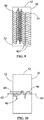
- the nested cooling channels 40 in the trailing edge portion 42 have an irregular contour, as shown in FIG. 9 and FIG. 10 .
- Each nested cooling channel 40 may have the same irregular contour as shown in FIG. 9 , or each nested cooling channel 40 may have a different irregular contour as shown in FIG. 10 .
- An irregular contour may be any non-repeating contour, such as, for example, a random contour. Referring to FIG.
- the lower nested cooling channel 40 is nested with respect to the upper nested cooling channel 40, because at least one portion of the lower nested cooling channel 40 extends to a radial height 60 above the radial heights 62, 64 of two portions of the upper nested cooling channel 40 on either side of that nested portion of the lower nested cooling channel 40.
- the airfoil 12 includes a CMC shell 22
- at least a portion of the nested cooling channels 40 may be formed between layers of the CMC material.
- all of the nested cooling channels 40 are formed between CMC layers.
- the nested cooling channels 40 are formed by machining the CMC material after formation of the CMC material.
- a sacrificial material is burned or pyrolyzed out either during or after formation of the CMC material to form the nested cooling channels 40.
- the metal part 30 may be formed by casting or alternatively by metal three-dimensional (3D) printing.
- the metal part 30 is formed as two metal pieces that are brazed or welded together, such as, for example, along line 4-4 of FIG. 3 .
- the two pieces are a first section 44 including the suction side 18 having the convex outer surface and a second section 46 including the pressure side 20 having the concave outer surface, with at least a portion of the nested cooling channels 40 being formed at one or both of the surfaces of the sections 44, 46.
- all of the nested cooling channels 40 are formed at the surface of the sections 44, 46.
- the metal part 30 may be formed as a single piece by metal 3D printing.
- Metal 3D printing enables precise creation of a turbine component 10 including complex nested cooling channels 40.
- metal 3D printing forms successive layers of material under computer control to create at least a portion of the turbine component 10.
- powdered metal is heated to melt or sinter the powder to the growing turbine component 10. Heating methods may include, but are not limited to, selective laser sintering (SLS), direct metal laser sintering (DMLS), selective laser melting (SLM), electron beam melting (EBM), and combinations thereof.
- SLS selective laser sintering
- DMLS direct metal laser sintering
- SLM selective laser melting
- EBM electron beam melting
- a 3D metal printer lays down metal powder, and then a high-powered laser melts that powder in certain predetermined locations based on a model from a computer-aided design (CAD) file. Once one layer is melted and formed, the 3D printer repeats the process by placing additional layers of metal powder on top of the first layer or where otherwise instructed, one at a time, until the entire metal component is
- the nested cooling channels 40 are preferably formed in the trailing edge portion 42 of the airfoil 12 to permit passage of a cooling fluid to cool the trailing edge portion 42.
- the nested cooling channels 40 may have any contour that increases the path length of the nested cooling channels 40 and provides nesting of neighboring nested cooling channels 40, including, but not limited to, wavy, zigzag, serpentine, sinusoidal, irregular, or combinations thereof.
- the nesting preferably compensates, at least in part, for any incidental blockage of one nested cooling channel 40 in that the neighboring nested cooling channels 40 may continue to provide cooling fluid on either side of the blocked nested cooling channel 40.
- the dimensions, contours, and/or locations of the nested cooling channels 40 are selected to permit cooling that maintains a substantially uniform temperature in the trailing edge portion 42 during operation of a turbine including the turbine component 10.
- the cross section of a nested cooling channel 40 may have any shape, including, but not limited to, a round shape, an elliptical shape, a racetrack shape, and a parallelogram.
- the size and shape of the cross section of the nested cooling channel 40 may vary from the first end 50 to the second end 54, depending on the local cooling effectiveness required of the nested cooling channel 40.
- one or more of the nested cooling channels 40 have an internal heat transfer enhancement feature.
- the internal heat transfer feature is one or more turbulators, one or more dimples, one or more grooves, or a combination thereof.
Landscapes
- Engineering & Computer Science (AREA)
- Mechanical Engineering (AREA)
- Chemical & Material Sciences (AREA)
- Materials Engineering (AREA)
- General Engineering & Computer Science (AREA)
- Optics & Photonics (AREA)
- Physics & Mathematics (AREA)
- Plasma & Fusion (AREA)
- Manufacturing & Machinery (AREA)
- Composite Materials (AREA)
- Architecture (AREA)
- Ceramic Engineering (AREA)
- Inorganic Chemistry (AREA)
- Chemical Kinetics & Catalysis (AREA)
- Metallurgy (AREA)
- Organic Chemistry (AREA)
- Turbine Rotor Nozzle Sealing (AREA)
- Laser Beam Processing (AREA)
Abstract
Description
- This invention was made with Government support under contract number DE-FE0024006 awarded by the Department of Energy. The Government has certain rights in the invention.
- The present embodiments are directed to methods and devices for cooling the trailing edge of a turbine airfoil. More specifically, the present embodiments are directed to nested cooling channels along the trailing edge of an airfoil of a turbine component.
- Modem high-efficiency combustion turbines have firing temperatures that exceed about 2000 °F (1093 °C), and firing temperatures continue to increase as demand for more efficient engines continues. Gas turbine components, such as nozzles and blades, are subjected to intense heat and external pressures in the hot gas path. These rigorous operating conditions are exacerbated by advances in the technology, which may include both increased operating temperatures and greater hot gas path pressures. As a result, components, such as nozzles and blades, are sometimes cooled by flowing a fluid through a manifold inserted into the core of the nozzle or blade, which exits the manifold through impingement holes into a post-impingement cavity, and which then exits the post-impingement cavity through apertures in the exterior wall of the nozzle or blade, in some cases forming a film layer of the fluid on the exterior of the nozzle or blade.
- The cooling of the trailing edge of a turbine airfoil is important to prolong its integrity in the hot furnace-like environment. While turbine airfoils are often made primarily of a nickel-based or a cobalt-based superalloy, turbine airfoils may alternatively have an outer portion made of one or more ceramic matrix composite (CMC) materials. CMC materials are generally better at handling higher temperatures than metals. Certain CMC materials include compositions having a ceramic matrix reinforced with coated fibers. The composition provides strong, lightweight, and heat-resistant materials with possible applications in a variety of different systems. The materials from which turbine components, such as nozzles or blades, are formed, combined with the particular conformations which the turbine components include, lead to certain inhibitions in the cooling efficacy of the cooling fluid systems. Maintaining a substantially uniform temperature of a turbine airfoil maximizes the useful life of the airfoil.
- The manufacture of a CMC part typically includes laying up pre-impregnated composite fibers having a matrix material already present (prepreg) to form the geometry of the part (pre-form), autoclaving and burning out the pre-form, infiltrating the burned-out pre-form with the melting matrix material, and any machining or further treatments of the pre-form. Infiltrating the pre-form may include depositing the ceramic matrix out of a gas mixture, pyrolyzing a pre-ceramic polymer, chemically reacting elements, sintering, generally in the temperature range of 925 to 1650 °C (1700 to 3000 °F), or electrophoretically depositing a ceramic powder. With respect to turbine airfoils, the CMC may be located over a metal spar to form only the outer surface of the airfoil.
- Examples of CMC materials include, but are not limited to, carbon-fiber-reinforced carbon (C/C), carbon-fiber-reinforced silicon carbide (C/SiC), silicon-carbide-fiber-reinforced silicon carbide (SiC/SiC), alumina-fiber-reinforced alumina (A1203/A1203), or combinations thereof. The CMC may have increased elongation, fracture toughness, thermal shock, dynamic load capability, and anisotropic properties as compared to a monolithic ceramic structure.
- In an embodiment, a turbine component includes a root and an airfoil extending from the root to a tip opposite the root. The airfoil forms a leading edge and a trailing edge portion extending to a trailing edge. A plurality of nested cooling channels in the trailing edge portion of the airfoil permit passage of a cooling fluid from an interior of the turbine component to an exterior of the turbine component at the trailing edge portion.
- In another embodiment, a method of making a turbine component includes forming an airfoil having a leading edge, a trailing edge portion extending to a trailing edge, and a plurality of nested cooling channels in the trailing edge portion. Each nested cooling channel fluidly connects an interior of the turbine component with an exterior of the turbine component at the trailing edge portion.
- In another embodiment, a method of cooling a turbine component includes supplying a cooling fluid to an interior of the turbine component. The turbine component includes a root and an airfoil extending from the root to a tip opposite the root. The airfoil forms a leading edge and a trailing edge portion extending to a trailing edge. The trailing edge portion has a plurality of nested cooling channels. The method also includes directing the cooling fluid through the nested cooling channels through the trailing edge portion of the airfoil. Each nested cooling channel fluidly connects the interior of the turbine component with an exterior of the turbine component at the trailing edge portion.
- Other features and advantages of the present invention will be apparent from the following more detailed description, taken in conjunction with the accompanying drawings which illustrate, by way of example, the principles of the invention.
-
-
FIG. 1 is a schematic perspective side view of a turbine component in an embodiment of the present disclosure. -
FIG. 2 is a schematic top view of the turbine component ofFIG. 1 with a CMC outer layer. -
FIG. 3 is a schematic top view of the turbine component ofFIG. 1 as a metal airfoil. -
FIG. 4 is a schematic partial cross sectional view taken along line 4-4 ofFIG. 3 . -
FIG. 5 is a schematic partial cross sectional view of the trailing edge portion of the turbine component ofFIG. 1 showing a nested wavy channel arrangement in an embodiment of the present disclosure. -
FIG. 6 is a schematic partial cross sectional view of the trailing edge portion of the turbine component ofFIG. 1 showing a nested zigzag cooling channel arrangement in an embodiment of the present disclosure. -
FIG. 7 is a schematic partial cross sectional view of the trailing edge portion of the turbine component ofFIG. 1 showing a nested serpentine cooling channel arrangement in an embodiment of the present disclosure. -
FIG. 8 is a schematic partial cross sectional view of the trailing edge portion of the turbine component ofFIG. 1 showing a nested sinusoidal channel arrangement in an embodiment of the present disclosure. -
FIG. 9 is a schematic partial cross sectional view of the trailing edge portion of the turbine component ofFIG. 1 showing a nested irregular channel arrangement in an embodiment of the present disclosure. -
FIG. 10 is a schematic partial cross sectional view of the trailing edge portion of the turbine component ofFIG. 1 showing two irregular channels in a nested arrangement in an embodiment of the present disclosure. - Wherever possible, the same reference numbers will be used throughout the drawings to represent the same parts.
- Provided is a method and a device for cooling the trailing edge of a turbine airfoil with nested cooling channels along the trailing edge of the turbine airfoil.
- Embodiments of the present disclosure, for example, in comparison to concepts failing to include one or more of the features disclosed herein, provide cooling in a turbine airfoil, provide a more uniform temperature in a cooled turbine airfoil, provide a turbine airfoil with an enhanced lifespan, compensate at least in part for a blocked cooling channel by cooling with a neighboring cooling channel, or combinations thereof
- As used herein, a nested cooling channel refers to a cooling channel having at least one portion extending between two portions of a neighboring cooling channel contour. When cooling channels are nested, a hot gas streamline crosses more than one cooling channel.
- As used herein, a trailing edge portion refers to a portion of an airfoil at the trailing edge without chambers or other void space aside from the cooling channels formed therein, as described herein.
- Referring to
FIG. 1 , aturbine component 10 includes aroot 11 and anairfoil 12 extending from theroot 11 at thebase 13 to atip 14 opposite thebase 13. In some embodiments, theturbine component 10 is a turbine nozzle. In some embodiments, theturbine component 10 is a turbine blade. The shape of theairfoil 12 includes a leadingedge 15, atrailing edge 16, asuction side 18 having a convex outer surface, and apressure side 20 having a concave outer surface opposite the convex outer surface. Although not shown inFIG. 1 , theturbine component 10 may also include an outer sidewall at thetip 14 of theairfoil 12 similar to theroot 11 at thebase 13 of theairfoil 12. - The generally arcuate contour of the
airfoil 12 is shown more clearly inFIG. 2 andFIG. 3 . Referring toFIG. 2 , theairfoil 12 includes a ceramic matrix composite (CMC)shell 22 mounted on ametal spar 24. Theairfoil 12 is formed as athin CMC shell 22 of one or more layers of CMC materials over themetal spar 24. Referring toFIG. 3 , theairfoil 12 is alternatively formed as ametal part 30. The metal part is preferably a high-temperature superalloy. In some embodiments, the high-temperature superalloy is a nickel-based high-temperature superalloy or a cobalt-based high-temperature superalloy. - In either case, the nested
cooling channels 40 in the trailingedge portion 42 permit a cooling fluid supplied to the inner portion of theairfoil 12 to flow through the trailingedge portion 42 and out of the trailingedge portion 42 during operation of a turbine including theturbine component 10. Theairfoil 12 also includes one ormore chambers 32 to which cooling fluid may be provided by way of theroot 11 or by way of thetip 14 of theturbine component 10. - Referring to
FIG. 4 , the trailingedge portion 42 of theturbine component 10 includes the nestedcooling channels 40 that open at afirst end 50 at aninterior surface 52 and asecond end 54 opposite thefirst end 50 at or near the trailingedge 16 to provide passage of a cooling fluid in a generally axial direction from the interior to the exterior of theturbine component 10. The nestedcooling channels 40 are preferably designed to be fluidly isolated from each other. In other words, each nestedcooling channel 40 is preferably only open at thefirst end 50 and thesecond end 54 and is fluidly isolated from neighboring nestedcooling channels 40. - The nested
cooling channels 40 in the trailingedge portion 42 may have any nested geometry, including, but not limited to, a wavy contour as shown inFIG. 5 , a zigzag contour as shown inFIG. 6 , a serpentine contour as shown inFIG. 7 , a sinusoidal contour as shown inFIG. 8 , or combinations thereof. In some embodiments, the nestedcooling channels 40 at or near the upper or lower edges of the trailingedge portion 42 may have a different pattern than the nestedcooling channels 40 in the center portion of the trailingedge portion 42 in order to provide more cooling at or near the upper and lower edges, as shown inFIG. 5 through FIG. 8 . The two ends 50, 54 of each nestedcooling channel 40 may be at the same radial height, as shown inFIGS. 5, 6, and 8 , or the two ends 50, 54 of a nestedcooling channel 40 may be at different radial heights, as shown inFIG. 7 . - In some embodiments, the nested
cooling channels 40 in the trailingedge portion 42 have an irregular contour, as shown inFIG. 9 and FIG. 10 . Each nestedcooling channel 40 may have the same irregular contour as shown inFIG. 9 , or each nestedcooling channel 40 may have a different irregular contour as shown inFIG. 10 . An irregular contour may be any non-repeating contour, such as, for example, a random contour. Referring toFIG. 10 , the lowernested cooling channel 40 is nested with respect to the uppernested cooling channel 40, because at least one portion of the lowernested cooling channel 40 extends to aradial height 60 above theradial heights nested cooling channel 40 on either side of that nested portion of the lowernested cooling channel 40. - When the
airfoil 12 includes aCMC shell 22, at least a portion of the nestedcooling channels 40 may be formed between layers of the CMC material. In some embodiments, all of the nestedcooling channels 40 are formed between CMC layers. In some embodiments, the nestedcooling channels 40 are formed by machining the CMC material after formation of the CMC material. In other embodiments, a sacrificial material is burned or pyrolyzed out either during or after formation of the CMC material to form the nestedcooling channels 40. - When the
airfoil 12 is formed as ametal part 30, the metal part may be formed by casting or alternatively by metal three-dimensional (3D) printing. In some embodiments, themetal part 30 is formed as two metal pieces that are brazed or welded together, such as, for example, along line 4-4 ofFIG. 3 . In such embodiments, the two pieces are a first section 44 including thesuction side 18 having the convex outer surface and asecond section 46 including thepressure side 20 having the concave outer surface, with at least a portion of the nestedcooling channels 40 being formed at one or both of the surfaces of thesections 44, 46. In some embodiments, all of the nestedcooling channels 40 are formed at the surface of thesections 44, 46. In other embodiments, themetal part 30 may be formed as a single piece by metal 3D printing. - Metal 3D printing enables precise creation of a
turbine component 10 including complex nestedcooling channels 40. In some embodiments, metal 3D printing forms successive layers of material under computer control to create at least a portion of theturbine component 10. In some embodiments, powdered metal is heated to melt or sinter the powder to the growingturbine component 10. Heating methods may include, but are not limited to, selective laser sintering (SLS), direct metal laser sintering (DMLS), selective laser melting (SLM), electron beam melting (EBM), and combinations thereof. In some embodiments, a 3D metal printer lays down metal powder, and then a high-powered laser melts that powder in certain predetermined locations based on a model from a computer-aided design (CAD) file. Once one layer is melted and formed, the 3D printer repeats the process by placing additional layers of metal powder on top of the first layer or where otherwise instructed, one at a time, until the entire metal component is fabricated. - The nested
cooling channels 40 are preferably formed in the trailingedge portion 42 of theairfoil 12 to permit passage of a cooling fluid to cool the trailingedge portion 42. The nestedcooling channels 40 may have any contour that increases the path length of the nestedcooling channels 40 and provides nesting of neighboring nestedcooling channels 40, including, but not limited to, wavy, zigzag, serpentine, sinusoidal, irregular, or combinations thereof. The nesting preferably compensates, at least in part, for any incidental blockage of one nestedcooling channel 40 in that the neighboring nestedcooling channels 40 may continue to provide cooling fluid on either side of the blocked nested coolingchannel 40. - In some embodiments, the dimensions, contours, and/or locations of the nested
cooling channels 40 are selected to permit cooling that maintains a substantially uniform temperature in the trailingedge portion 42 during operation of a turbine including theturbine component 10. The cross section of a nestedcooling channel 40 may have any shape, including, but not limited to, a round shape, an elliptical shape, a racetrack shape, and a parallelogram. The size and shape of the cross section of the nestedcooling channel 40 may vary from thefirst end 50 to thesecond end 54, depending on the local cooling effectiveness required of the nestedcooling channel 40. In some embodiments, one or more of the nestedcooling channels 40 have an internal heat transfer enhancement feature. In some embodiments, the internal heat transfer feature is one or more turbulators, one or more dimples, one or more grooves, or a combination thereof. - While the invention has been described with reference to one or more embodiments, it will be understood by those skilled in the art that various changes may be made and equivalents may be substituted for elements thereof without departing from the scope of the invention. In addition, many modifications may be made to adapt a particular situation or material to the teachings of the invention without departing from the essential scope thereof. Therefore, it is intended that the invention not be limited to the particular embodiment disclosed as the best mode contemplated for carrying out this invention, but that the invention will include all embodiments falling within the scope of the appended claims. In addition, all numerical values identified in the detailed description shall be interpreted as though the precise and approximate values are both expressly identified.
- Various aspects and embodiments of the present invention are defined by the following numbered clauses:
- 1. A turbine component comprising:
- a root; and
- an airfoil extending from the root to a tip opposite the root, the airfoil forming a leading edge and a trailing edge portion extending to a trailing edge;
- wherein a plurality of nested cooling channels in the trailing edge portion of the airfoil permit passage of a cooling fluid from an interior of the turbine component to an exterior of the turbine component at the trailing edge portion.
- 2. The turbine component of clause 1, wherein the airfoil comprises a metal spar and a shell over the metal spar, the shell comprising a ceramic matrix composite material.
- 3. The turbine component of any preceding clause, wherein at least a portion of the plurality of nested cooling channels are formed between layers of the ceramic matrix composite material.
- 4. The turbine component of any preceding clause, wherein the airfoil is formed of a high-temperature superalloy by metal three-dimensional printing.
- 5. The turbine component of any preceding clause, wherein the airfoil comprises a first section and a second section welded or brazed to the first section to form the airfoil, the first section and the second section being formed by metal three-dimensional printing and at least a portion of the plurality of nested cooling channels being formed at a surface of the first section or the second section.
- 6. The turbine component of any preceding clause, wherein the plurality of nested cooling channels have a nested geometry selected from the group consisting of wavy, zigzag, serpentine, sinusoidal, irregular, and combinations thereof.
- 7. A method of making a turbine component comprising:
- forming an airfoil having a leading edge, a trailing edge portion extending to a trailing edge, and a plurality of nested cooling channels in the trailing edge portion, each of the plurality of nested cooling channels fluidly connecting an interior of the turbine component with an exterior of the turbine component at the trailing edge portion.
- 8. The method of any preceding clause, wherein the forming comprises forming a shell over a metal spar to form the airfoil, wherein the shell comprises a ceramic matrix composite material.
- 9. The method of any preceding clause, further comprising forming the metal spar.
- 10. The method of any preceding clause, further comprising forming at least a portion of the plurality of nested cooling channels between layers of the ceramic matrix composite material.
- 11. The method of any preceding clause, wherein the forming comprises metal three-dimensional printing of a high-temperature superalloy to form the airfoil.
- 12. The method of any preceding clause, wherein the forming comprises metal three-dimensionally printing a first section and a second section and welding or brazing the first section to the second section to form the airfoil, at least a portion of the plurality of nested cooling channels being formed at a surface of the first section or the second section.
- 13. The method of any preceding clause, wherein the plurality of nested cooling channels have a geometry selected from the group consisting of wavy, zigzag, serpentine, sinusoidal, irregular, and combinations thereof.
- 14. A method of cooling a turbine component comprising:
- supplying a cooling fluid to an interior of the turbine component, the turbine component comprising:
- a root; and
- an airfoil extending from the root to a tip opposite the root, the airfoil forming a leading edge and a trailing edge portion extending to a trailing edge, the trailing edge portion having a plurality of nested cooling channels; and
- directing the cooling fluid through the plurality of nested cooling channels through the trailing edge portion of the airfoil, each of the plurality of nested cooling channels fluidly connecting the interior of the turbine component with an exterior of the turbine component at the trailing edge portion.
- supplying a cooling fluid to an interior of the turbine component, the turbine component comprising:
- 15. The method of any preceding clause, further comprising operating a turbine comprising the turbine component.
- 16. The method of any preceding clause, wherein the airfoil comprises a metal spar and a shell over the metal spar, the shell comprising a ceramic matrix composite material.
- 17. The method of any preceding clause, wherein at least a portion of the plurality of nested cooling channels are formed between layers of the ceramic matrix composite material.
- 18. The method of any preceding clause, wherein the airfoil is formed of a high-temperature superalloy by metal three-dimensional printing.
- 19. The method of any preceding clause, wherein the airfoil comprises a first section and a second section welded or brazed to the first section to form the airfoil, the first section and the second section being formed by metal three-dimensional printing and at least a portion of the plurality of nested cooling channels being formed at a surface of the first section or the second section.
- 20. The method of any preceding clause, wherein the plurality of nested cooling channels have a geometry selected from the group consisting of wavy, zigzag, serpentine, sinusoidal, irregular, and combinations thereof.
Claims (10)
- A turbine component (10) comprising:a root (11); andan airfoil (12) extending from the root (11) to a tip (14) opposite the root (11), the airfoil (12) forming a leading edge (15) and a trailing edge portion (42) extending to a trailing edge (16);wherein a plurality of nested cooling channels (40) in the trailing edge portion (42) of the airfoil (12) permit passage of a cooling fluid from an interior of the turbine component (10) to an exterior of the turbine component (10) at the trailing edge portion (42).
- The turbine component (10) of claim 1, wherein the airfoil (12) comprises a metal spar (24) and a shell over the metal spar (24), the shell comprising a ceramic matrix composite material.
- The turbine component (10) of claim 2, wherein at least a portion of the plurality of nested cooling channels (40) are formed between layers of the ceramic matrix composite material.
- The turbine component (10) of claim 1, 2 or 3, wherein the airfoil (12) is formed of a high-temperature superalloy by metal three-dimensional printing.
- The turbine component (10) of any preceding claim, wherein the plurality of nested cooling channels (40) have a nested geometry selected from the group consisting of wavy, zigzag, serpentine, sinusoidal, irregular, and combinations thereof.
- A method of making a turbine component (10) comprising:forming an airfoil (12) having a leading edge (15), a trailing edge portion (42) extending to a trailing edge (16), and a plurality of nested cooling channels (40) in the trailing edge portion (42), each of the plurality of nested cooling channels (40) fluidly connecting an interior of the turbine component (10) with an exterior of the turbine component (10) at the trailing edge portion (42).
- The method of claim 6, wherein the forming comprises forming a shell over a metal spar (24) to form the airfoil (12), wherein the shell comprises a ceramic matrix composite material.
- The method of claim 7 further comprising forming at least a portion of the plurality of nested cooling channels (40) between layers of the ceramic matrix composite material.
- The method of claim 6, wherein the forming comprises metal three-dimensional printing of a high-temperature superalloy to form the airfoil (12).
- A method of cooling a turbine component (10) comprising:supplying a cooling fluid to an interior of the turbine component (10), the turbine component (10) comprising:a root (11); andan airfoil (12) extending from the root (11) to a tip (14) opposite the root (11), the airfoil (12) forming a leading edge (15) and a trailing edge portion (42) extending to a trailing edge (16), the trailing edge portion (42) having a plurality of nested cooling channels (40); anddirecting the cooling fluid through the plurality of nested cooling channels (40) through the trailing edge portion (42) of the airfoil (12), each of the plurality of nested cooling channels (40) fluidly connecting the interior of the turbine component (10) with an exterior of the turbine component (10) at the trailing edge portion (42).
Applications Claiming Priority (1)
| Application Number | Priority Date | Filing Date | Title |
|---|---|---|---|
| US15/174,182 US10287894B2 (en) | 2016-06-06 | 2016-06-06 | Turbine component and methods of making and cooling a turbine component |
Publications (2)
| Publication Number | Publication Date |
|---|---|
| EP3255247A1 true EP3255247A1 (en) | 2017-12-13 |
| EP3255247B1 EP3255247B1 (en) | 2024-04-10 |
Family
ID=59009591
Family Applications (1)
| Application Number | Title | Priority Date | Filing Date |
|---|---|---|---|
| EP17174357.8A Active EP3255247B1 (en) | 2016-06-06 | 2017-06-02 | Turbine component and methods of making and cooling a turbine component |
Country Status (3)
| Country | Link |
|---|---|
| US (1) | US10287894B2 (en) |
| EP (1) | EP3255247B1 (en) |
| JP (1) | JP2018021545A (en) |
Cited By (1)
| Publication number | Priority date | Publication date | Assignee | Title |
|---|---|---|---|---|
| WO2018141574A1 (en) * | 2017-01-31 | 2018-08-09 | Siemens Aktiengesellschaft | Cmc turbine component with complex cooling structures and method for the production thereof |
Families Citing this family (13)
| Publication number | Priority date | Publication date | Assignee | Title |
|---|---|---|---|---|
| US10450950B2 (en) | 2016-10-26 | 2019-10-22 | General Electric Company | Turbomachine blade with trailing edge cooling circuit |
| US10598028B2 (en) | 2016-10-26 | 2020-03-24 | General Electric Company | Edge coupon including cooling circuit for airfoil |
| US10352176B2 (en) | 2016-10-26 | 2019-07-16 | General Electric Company | Cooling circuits for a multi-wall blade |
| US10301946B2 (en) | 2016-10-26 | 2019-05-28 | General Electric Company | Partially wrapped trailing edge cooling circuits with pressure side impingements |
| US10450875B2 (en) | 2016-10-26 | 2019-10-22 | General Electric Company | Varying geometries for cooling circuits of turbine blades |
| US10273810B2 (en) | 2016-10-26 | 2019-04-30 | General Electric Company | Partially wrapped trailing edge cooling circuit with pressure side serpentine cavities |
| US10233761B2 (en) | 2016-10-26 | 2019-03-19 | General Electric Company | Turbine airfoil trailing edge coolant passage created by cover |
| US10309227B2 (en) * | 2016-10-26 | 2019-06-04 | General Electric Company | Multi-turn cooling circuits for turbine blades |
| US10465521B2 (en) | 2016-10-26 | 2019-11-05 | General Electric Company | Turbine airfoil coolant passage created in cover |
| US11426818B2 (en) | 2018-08-10 | 2022-08-30 | The Research Foundation for the State University | Additive manufacturing processes and additively manufactured products |
| US12017212B2 (en) * | 2019-09-08 | 2024-06-25 | Spf Technologies Llc | High pressure fluidic devices having volume integrity and homogenous flow |
| US11814965B2 (en) | 2021-11-10 | 2023-11-14 | General Electric Company | Turbomachine blade trailing edge cooling circuit with turn passage having set of obstructions |
| US12467369B2 (en) | 2023-08-22 | 2025-11-11 | General Electric Company | Composite component having an additively printed inner portion |
Citations (4)
| Publication number | Priority date | Publication date | Assignee | Title |
|---|---|---|---|---|
| US6514046B1 (en) * | 2000-09-29 | 2003-02-04 | Siemens Westinghouse Power Corporation | Ceramic composite vane with metallic substructure |
| US20030059577A1 (en) * | 2001-09-24 | 2003-03-27 | Siemens Westinghouse Power Corporation | Ceramic matrix composite structure having integral cooling passages and method of manufacture |
| US20050281673A1 (en) * | 2004-06-17 | 2005-12-22 | Draper Samuel D | Drillable super blades |
| US8790083B1 (en) * | 2009-11-17 | 2014-07-29 | Florida Turbine Technologies, Inc. | Turbine airfoil with trailing edge cooling |
Family Cites Families (9)
| Publication number | Priority date | Publication date | Assignee | Title |
|---|---|---|---|---|
| JP2003129862A (en) * | 2001-10-23 | 2003-05-08 | Toshiba Corp | Turbine blade manufacturing method |
| US7758314B2 (en) * | 2003-03-12 | 2010-07-20 | Florida Turbine Technologies, Inc. | Tungsten shell for a spar and shell turbine vane |
| US7645122B1 (en) | 2006-12-01 | 2010-01-12 | Florida Turbine Technologies, Inc. | Turbine rotor blade with a nested parallel serpentine flow cooling circuit |
| US8235670B2 (en) * | 2009-06-17 | 2012-08-07 | Siemens Energy, Inc. | Interlocked CMC airfoil |
| US9175568B2 (en) * | 2010-06-22 | 2015-11-03 | Honeywell International Inc. | Methods for manufacturing turbine components |
| CH705631A1 (en) * | 2011-10-31 | 2013-05-15 | Alstom Technology Ltd | Components or coupon for use under high thermal load and voltage and method for producing such a component, or of such a coupon. |
| US9393620B2 (en) * | 2012-12-14 | 2016-07-19 | United Technologies Corporation | Uber-cooled turbine section component made by additive manufacturing |
| JP6404312B2 (en) * | 2013-03-15 | 2018-10-10 | ユナイテッド テクノロジーズ コーポレイションUnited Technologies Corporation | Additional production of baffles, covers and molds |
| US9347320B2 (en) * | 2013-10-23 | 2016-05-24 | General Electric Company | Turbine bucket profile yielding improved throat |
-
2016
- 2016-06-06 US US15/174,182 patent/US10287894B2/en active Active
-
2017
- 2017-06-01 JP JP2017108889A patent/JP2018021545A/en active Pending
- 2017-06-02 EP EP17174357.8A patent/EP3255247B1/en active Active
Patent Citations (4)
| Publication number | Priority date | Publication date | Assignee | Title |
|---|---|---|---|---|
| US6514046B1 (en) * | 2000-09-29 | 2003-02-04 | Siemens Westinghouse Power Corporation | Ceramic composite vane with metallic substructure |
| US20030059577A1 (en) * | 2001-09-24 | 2003-03-27 | Siemens Westinghouse Power Corporation | Ceramic matrix composite structure having integral cooling passages and method of manufacture |
| US20050281673A1 (en) * | 2004-06-17 | 2005-12-22 | Draper Samuel D | Drillable super blades |
| US8790083B1 (en) * | 2009-11-17 | 2014-07-29 | Florida Turbine Technologies, Inc. | Turbine airfoil with trailing edge cooling |
Cited By (1)
| Publication number | Priority date | Publication date | Assignee | Title |
|---|---|---|---|---|
| WO2018141574A1 (en) * | 2017-01-31 | 2018-08-09 | Siemens Aktiengesellschaft | Cmc turbine component with complex cooling structures and method for the production thereof |
Also Published As
| Publication number | Publication date |
|---|---|
| JP2018021545A (en) | 2018-02-08 |
| EP3255247B1 (en) | 2024-04-10 |
| US20170350259A1 (en) | 2017-12-07 |
| US10287894B2 (en) | 2019-05-14 |
Similar Documents
| Publication | Publication Date | Title |
|---|---|---|
| US10287894B2 (en) | Turbine component and methods of making and cooling a turbine component | |
| US11333024B2 (en) | Turbine component and methods of making and cooling a turbine component | |
| US11319816B2 (en) | Turbine component and methods of making and cooling a turbine component | |
| EP4086429B1 (en) | Turbine blade repair method using additive manufacturing | |
| US9393620B2 (en) | Uber-cooled turbine section component made by additive manufacturing | |
| Bunker | Gas turbine cooling: moving from macro to micro cooling | |
| US9394796B2 (en) | Turbine component and methods of assembling the same | |
| EP3084138B1 (en) | Gas turbine engine blade with ceramic tip and cooling arrangement | |
| US7824150B1 (en) | Multiple piece turbine airfoil | |
| WO2014052323A1 (en) | Uber-cooled turbine section component made by additive manufacturing | |
| CN104343469A (en) | Airfoil with trailing edge supplement structure | |
| CN114867930A (en) | Turbine rotor blade with airfoil seal and coolant delivery channel between adjacent wheel space portions by additive manufacturing | |
| JP2018505983A (en) | Hybrid ceramic matrix composite | |
| CN106925721B (en) | Method and assembly for forming a component having an internal passage defined therein | |
| JP2020097930A (en) | Turbine blade tip cooling system including tip rail cooling insert | |
| US20180171806A1 (en) | Three-dimensionally woven ceramic matrix composite turbine blade | |
| CN107042289B (en) | Method and assembly for forming a component having an internal passageway using a core sleeve | |
| CN106907187A (en) | Product and the method for forming product | |
| JP2014148167A (en) | Multilayer component and fabrication process thereof | |
| CN119507991A (en) | Composite component with additively printed inner portion |
Legal Events
| Date | Code | Title | Description |
|---|---|---|---|
| PUAI | Public reference made under article 153(3) epc to a published international application that has entered the european phase |
Free format text: ORIGINAL CODE: 0009012 |
|
| STAA | Information on the status of an ep patent application or granted ep patent |
Free format text: STATUS: THE APPLICATION HAS BEEN PUBLISHED |
|
| AK | Designated contracting states |
Kind code of ref document: A1 Designated state(s): AL AT BE BG CH CY CZ DE DK EE ES FI FR GB GR HR HU IE IS IT LI LT LU LV MC MK MT NL NO PL PT RO RS SE SI SK SM TR |
|
| AX | Request for extension of the european patent |
Extension state: BA ME |
|
| STAA | Information on the status of an ep patent application or granted ep patent |
Free format text: STATUS: REQUEST FOR EXAMINATION WAS MADE |
|
| 17P | Request for examination filed |
Effective date: 20180613 |
|
| RBV | Designated contracting states (corrected) |
Designated state(s): AL AT BE BG CH CY CZ DE DK EE ES FI FR GB GR HR HU IE IS IT LI LT LU LV MC MK MT NL NO PL PT RO RS SE SI SK SM TR |
|
| STAA | Information on the status of an ep patent application or granted ep patent |
Free format text: STATUS: EXAMINATION IS IN PROGRESS |
|
| 17Q | First examination report despatched |
Effective date: 20201118 |
|
| RAP1 | Party data changed (applicant data changed or rights of an application transferred) |
Owner name: GENERAL ELECTRIC TECHNOLOGY GMBH |
|
| GRAP | Despatch of communication of intention to grant a patent |
Free format text: ORIGINAL CODE: EPIDOSNIGR1 |
|
| STAA | Information on the status of an ep patent application or granted ep patent |
Free format text: STATUS: GRANT OF PATENT IS INTENDED |
|
| INTG | Intention to grant announced |
Effective date: 20240108 |
|
| GRAS | Grant fee paid |
Free format text: ORIGINAL CODE: EPIDOSNIGR3 |
|
| GRAA | (expected) grant |
Free format text: ORIGINAL CODE: 0009210 |
|
| STAA | Information on the status of an ep patent application or granted ep patent |
Free format text: STATUS: THE PATENT HAS BEEN GRANTED |
|
| AK | Designated contracting states |
Kind code of ref document: B1 Designated state(s): AL AT BE BG CH CY CZ DE DK EE ES FI FR GB GR HR HU IE IS IT LI LT LU LV MC MK MT NL NO PL PT RO RS SE SI SK SM TR |
|
| REG | Reference to a national code |
Ref country code: GB Ref legal event code: FG4D |
|
| REG | Reference to a national code |
Ref country code: CH Ref legal event code: EP |
|
| REG | Reference to a national code |
Ref country code: DE Ref legal event code: R096 Ref document number: 602017080790 Country of ref document: DE |
|
| REG | Reference to a national code |
Ref country code: IE Ref legal event code: FG4D |
|
| REG | Reference to a national code |
Ref country code: LT Ref legal event code: MG9D |
|
| REG | Reference to a national code |
Ref country code: NL Ref legal event code: MP Effective date: 20240410 |
|
| REG | Reference to a national code |
Ref country code: AT Ref legal event code: MK05 Ref document number: 1675095 Country of ref document: AT Kind code of ref document: T Effective date: 20240410 |
|
| PG25 | Lapsed in a contracting state [announced via postgrant information from national office to epo] |
Ref country code: NL Free format text: LAPSE BECAUSE OF FAILURE TO SUBMIT A TRANSLATION OF THE DESCRIPTION OR TO PAY THE FEE WITHIN THE PRESCRIBED TIME-LIMIT Effective date: 20240410 |
|
| PG25 | Lapsed in a contracting state [announced via postgrant information from national office to epo] |
Ref country code: NL Free format text: LAPSE BECAUSE OF FAILURE TO SUBMIT A TRANSLATION OF THE DESCRIPTION OR TO PAY THE FEE WITHIN THE PRESCRIBED TIME-LIMIT Effective date: 20240410 |
|
| PG25 | Lapsed in a contracting state [announced via postgrant information from national office to epo] |
Ref country code: IS Free format text: LAPSE BECAUSE OF FAILURE TO SUBMIT A TRANSLATION OF THE DESCRIPTION OR TO PAY THE FEE WITHIN THE PRESCRIBED TIME-LIMIT Effective date: 20240810 |
|
| PG25 | Lapsed in a contracting state [announced via postgrant information from national office to epo] |
Ref country code: BG Free format text: LAPSE BECAUSE OF FAILURE TO SUBMIT A TRANSLATION OF THE DESCRIPTION OR TO PAY THE FEE WITHIN THE PRESCRIBED TIME-LIMIT Effective date: 20240410 |
|
| PG25 | Lapsed in a contracting state [announced via postgrant information from national office to epo] |
Ref country code: FI Free format text: LAPSE BECAUSE OF FAILURE TO SUBMIT A TRANSLATION OF THE DESCRIPTION OR TO PAY THE FEE WITHIN THE PRESCRIBED TIME-LIMIT Effective date: 20240410 Ref country code: HR Free format text: LAPSE BECAUSE OF FAILURE TO SUBMIT A TRANSLATION OF THE DESCRIPTION OR TO PAY THE FEE WITHIN THE PRESCRIBED TIME-LIMIT Effective date: 20240410 |
|
| PG25 | Lapsed in a contracting state [announced via postgrant information from national office to epo] |
Ref country code: GR Free format text: LAPSE BECAUSE OF FAILURE TO SUBMIT A TRANSLATION OF THE DESCRIPTION OR TO PAY THE FEE WITHIN THE PRESCRIBED TIME-LIMIT Effective date: 20240711 |
|
| PG25 | Lapsed in a contracting state [announced via postgrant information from national office to epo] |
Ref country code: PT Free format text: LAPSE BECAUSE OF FAILURE TO SUBMIT A TRANSLATION OF THE DESCRIPTION OR TO PAY THE FEE WITHIN THE PRESCRIBED TIME-LIMIT Effective date: 20240812 |
|
| PG25 | Lapsed in a contracting state [announced via postgrant information from national office to epo] |
Ref country code: ES Free format text: LAPSE BECAUSE OF FAILURE TO SUBMIT A TRANSLATION OF THE DESCRIPTION OR TO PAY THE FEE WITHIN THE PRESCRIBED TIME-LIMIT Effective date: 20240410 |
|
| PG25 | Lapsed in a contracting state [announced via postgrant information from national office to epo] |
Ref country code: AT Free format text: LAPSE BECAUSE OF FAILURE TO SUBMIT A TRANSLATION OF THE DESCRIPTION OR TO PAY THE FEE WITHIN THE PRESCRIBED TIME-LIMIT Effective date: 20240410 |
|
| PG25 | Lapsed in a contracting state [announced via postgrant information from national office to epo] |
Ref country code: PL Free format text: LAPSE BECAUSE OF FAILURE TO SUBMIT A TRANSLATION OF THE DESCRIPTION OR TO PAY THE FEE WITHIN THE PRESCRIBED TIME-LIMIT Effective date: 20240410 |
|
| PG25 | Lapsed in a contracting state [announced via postgrant information from national office to epo] |
Ref country code: LV Free format text: LAPSE BECAUSE OF FAILURE TO SUBMIT A TRANSLATION OF THE DESCRIPTION OR TO PAY THE FEE WITHIN THE PRESCRIBED TIME-LIMIT Effective date: 20240410 |
|
| PG25 | Lapsed in a contracting state [announced via postgrant information from national office to epo] |
Ref country code: PT Free format text: LAPSE BECAUSE OF FAILURE TO SUBMIT A TRANSLATION OF THE DESCRIPTION OR TO PAY THE FEE WITHIN THE PRESCRIBED TIME-LIMIT Effective date: 20240812 Ref country code: PL Free format text: LAPSE BECAUSE OF FAILURE TO SUBMIT A TRANSLATION OF THE DESCRIPTION OR TO PAY THE FEE WITHIN THE PRESCRIBED TIME-LIMIT Effective date: 20240410 Ref country code: NO Free format text: LAPSE BECAUSE OF FAILURE TO SUBMIT A TRANSLATION OF THE DESCRIPTION OR TO PAY THE FEE WITHIN THE PRESCRIBED TIME-LIMIT Effective date: 20240710 Ref country code: LV Free format text: LAPSE BECAUSE OF FAILURE TO SUBMIT A TRANSLATION OF THE DESCRIPTION OR TO PAY THE FEE WITHIN THE PRESCRIBED TIME-LIMIT Effective date: 20240410 Ref country code: IS Free format text: LAPSE BECAUSE OF FAILURE TO SUBMIT A TRANSLATION OF THE DESCRIPTION OR TO PAY THE FEE WITHIN THE PRESCRIBED TIME-LIMIT Effective date: 20240810 Ref country code: HR Free format text: LAPSE BECAUSE OF FAILURE TO SUBMIT A TRANSLATION OF THE DESCRIPTION OR TO PAY THE FEE WITHIN THE PRESCRIBED TIME-LIMIT Effective date: 20240410 Ref country code: GR Free format text: LAPSE BECAUSE OF FAILURE TO SUBMIT A TRANSLATION OF THE DESCRIPTION OR TO PAY THE FEE WITHIN THE PRESCRIBED TIME-LIMIT Effective date: 20240711 Ref country code: FI Free format text: LAPSE BECAUSE OF FAILURE TO SUBMIT A TRANSLATION OF THE DESCRIPTION OR TO PAY THE FEE WITHIN THE PRESCRIBED TIME-LIMIT Effective date: 20240410 Ref country code: ES Free format text: LAPSE BECAUSE OF FAILURE TO SUBMIT A TRANSLATION OF THE DESCRIPTION OR TO PAY THE FEE WITHIN THE PRESCRIBED TIME-LIMIT Effective date: 20240410 Ref country code: BG Free format text: LAPSE BECAUSE OF FAILURE TO SUBMIT A TRANSLATION OF THE DESCRIPTION OR TO PAY THE FEE WITHIN THE PRESCRIBED TIME-LIMIT Effective date: 20240410 Ref country code: AT Free format text: LAPSE BECAUSE OF FAILURE TO SUBMIT A TRANSLATION OF THE DESCRIPTION OR TO PAY THE FEE WITHIN THE PRESCRIBED TIME-LIMIT Effective date: 20240410 Ref country code: RS Free format text: LAPSE BECAUSE OF FAILURE TO SUBMIT A TRANSLATION OF THE DESCRIPTION OR TO PAY THE FEE WITHIN THE PRESCRIBED TIME-LIMIT Effective date: 20240710 |
|
| REG | Reference to a national code |
Ref country code: DE Ref legal event code: R097 Ref document number: 602017080790 Country of ref document: DE |
|
| PG25 | Lapsed in a contracting state [announced via postgrant information from national office to epo] |
Ref country code: DK Free format text: LAPSE BECAUSE OF FAILURE TO SUBMIT A TRANSLATION OF THE DESCRIPTION OR TO PAY THE FEE WITHIN THE PRESCRIBED TIME-LIMIT Effective date: 20240410 |
|
| PG25 | Lapsed in a contracting state [announced via postgrant information from national office to epo] |
Ref country code: EE Free format text: LAPSE BECAUSE OF FAILURE TO SUBMIT A TRANSLATION OF THE DESCRIPTION OR TO PAY THE FEE WITHIN THE PRESCRIBED TIME-LIMIT Effective date: 20240410 |
|
| PG25 | Lapsed in a contracting state [announced via postgrant information from national office to epo] |
Ref country code: CZ Free format text: LAPSE BECAUSE OF FAILURE TO SUBMIT A TRANSLATION OF THE DESCRIPTION OR TO PAY THE FEE WITHIN THE PRESCRIBED TIME-LIMIT Effective date: 20240410 |
|
| PG25 | Lapsed in a contracting state [announced via postgrant information from national office to epo] |
Ref country code: RO Free format text: LAPSE BECAUSE OF FAILURE TO SUBMIT A TRANSLATION OF THE DESCRIPTION OR TO PAY THE FEE WITHIN THE PRESCRIBED TIME-LIMIT Effective date: 20240410 Ref country code: SK Free format text: LAPSE BECAUSE OF FAILURE TO SUBMIT A TRANSLATION OF THE DESCRIPTION OR TO PAY THE FEE WITHIN THE PRESCRIBED TIME-LIMIT Effective date: 20240410 |
|
| PG25 | Lapsed in a contracting state [announced via postgrant information from national office to epo] |
Ref country code: SM Free format text: LAPSE BECAUSE OF FAILURE TO SUBMIT A TRANSLATION OF THE DESCRIPTION OR TO PAY THE FEE WITHIN THE PRESCRIBED TIME-LIMIT Effective date: 20240410 |
|
| PG25 | Lapsed in a contracting state [announced via postgrant information from national office to epo] |
Ref country code: SM Free format text: LAPSE BECAUSE OF FAILURE TO SUBMIT A TRANSLATION OF THE DESCRIPTION OR TO PAY THE FEE WITHIN THE PRESCRIBED TIME-LIMIT Effective date: 20240410 Ref country code: SK Free format text: LAPSE BECAUSE OF FAILURE TO SUBMIT A TRANSLATION OF THE DESCRIPTION OR TO PAY THE FEE WITHIN THE PRESCRIBED TIME-LIMIT Effective date: 20240410 Ref country code: RO Free format text: LAPSE BECAUSE OF FAILURE TO SUBMIT A TRANSLATION OF THE DESCRIPTION OR TO PAY THE FEE WITHIN THE PRESCRIBED TIME-LIMIT Effective date: 20240410 Ref country code: EE Free format text: LAPSE BECAUSE OF FAILURE TO SUBMIT A TRANSLATION OF THE DESCRIPTION OR TO PAY THE FEE WITHIN THE PRESCRIBED TIME-LIMIT Effective date: 20240410 Ref country code: DK Free format text: LAPSE BECAUSE OF FAILURE TO SUBMIT A TRANSLATION OF THE DESCRIPTION OR TO PAY THE FEE WITHIN THE PRESCRIBED TIME-LIMIT Effective date: 20240410 Ref country code: CZ Free format text: LAPSE BECAUSE OF FAILURE TO SUBMIT A TRANSLATION OF THE DESCRIPTION OR TO PAY THE FEE WITHIN THE PRESCRIBED TIME-LIMIT Effective date: 20240410 Ref country code: MC Free format text: LAPSE BECAUSE OF FAILURE TO SUBMIT A TRANSLATION OF THE DESCRIPTION OR TO PAY THE FEE WITHIN THE PRESCRIBED TIME-LIMIT Effective date: 20240410 |
|
| REG | Reference to a national code |
Ref country code: CH Ref legal event code: PL |
|
| PG25 | Lapsed in a contracting state [announced via postgrant information from national office to epo] |
Ref country code: IT Free format text: LAPSE BECAUSE OF FAILURE TO SUBMIT A TRANSLATION OF THE DESCRIPTION OR TO PAY THE FEE WITHIN THE PRESCRIBED TIME-LIMIT Effective date: 20240410 |
|
| PLBE | No opposition filed within time limit |
Free format text: ORIGINAL CODE: 0009261 |
|
| STAA | Information on the status of an ep patent application or granted ep patent |
Free format text: STATUS: NO OPPOSITION FILED WITHIN TIME LIMIT |
|
| PG25 | Lapsed in a contracting state [announced via postgrant information from national office to epo] |
Ref country code: LU Free format text: LAPSE BECAUSE OF NON-PAYMENT OF DUE FEES Effective date: 20240602 |
|
| 26N | No opposition filed |
Effective date: 20250113 |
|
| GBPC | Gb: european patent ceased through non-payment of renewal fee |
Effective date: 20240710 |
|
| PG25 | Lapsed in a contracting state [announced via postgrant information from national office to epo] |
Ref country code: IE Free format text: LAPSE BECAUSE OF NON-PAYMENT OF DUE FEES Effective date: 20240602 |
|
| PG25 | Lapsed in a contracting state [announced via postgrant information from national office to epo] |
Ref country code: SI Free format text: LAPSE BECAUSE OF FAILURE TO SUBMIT A TRANSLATION OF THE DESCRIPTION OR TO PAY THE FEE WITHIN THE PRESCRIBED TIME-LIMIT Effective date: 20240410 Ref country code: CH Free format text: LAPSE BECAUSE OF NON-PAYMENT OF DUE FEES Effective date: 20240630 Ref country code: BE Free format text: LAPSE BECAUSE OF NON-PAYMENT OF DUE FEES Effective date: 20240630 |
|
| PG25 | Lapsed in a contracting state [announced via postgrant information from national office to epo] |
Ref country code: FR Free format text: LAPSE BECAUSE OF NON-PAYMENT OF DUE FEES Effective date: 20240610 |
|
| PG25 | Lapsed in a contracting state [announced via postgrant information from national office to epo] |
Ref country code: GB Free format text: LAPSE BECAUSE OF NON-PAYMENT OF DUE FEES Effective date: 20240710 |
|
| REG | Reference to a national code |
Ref country code: BE Ref legal event code: MM Effective date: 20240630 |
|
| PGFP | Annual fee paid to national office [announced via postgrant information from national office to epo] |
Ref country code: DE Payment date: 20250520 Year of fee payment: 9 |
|
| PG25 | Lapsed in a contracting state [announced via postgrant information from national office to epo] |
Ref country code: SE Free format text: LAPSE BECAUSE OF FAILURE TO SUBMIT A TRANSLATION OF THE DESCRIPTION OR TO PAY THE FEE WITHIN THE PRESCRIBED TIME-LIMIT Effective date: 20240410 |
|
| PG25 | Lapsed in a contracting state [announced via postgrant information from national office to epo] |
Ref country code: CY Free format text: LAPSE BECAUSE OF FAILURE TO SUBMIT A TRANSLATION OF THE DESCRIPTION OR TO PAY THE FEE WITHIN THE PRESCRIBED TIME-LIMIT; INVALID AB INITIO Effective date: 20170602 |
|
| PG25 | Lapsed in a contracting state [announced via postgrant information from national office to epo] |
Ref country code: HU Free format text: LAPSE BECAUSE OF FAILURE TO SUBMIT A TRANSLATION OF THE DESCRIPTION OR TO PAY THE FEE WITHIN THE PRESCRIBED TIME-LIMIT; INVALID AB INITIO Effective date: 20170602 |