EP3255235B1 - Hinge providing cushioning effect and apparatus provided with the hinge - Google Patents
Hinge providing cushioning effect and apparatus provided with the hinge Download PDFInfo
- Publication number
- EP3255235B1 EP3255235B1 EP15880826.1A EP15880826A EP3255235B1 EP 3255235 B1 EP3255235 B1 EP 3255235B1 EP 15880826 A EP15880826 A EP 15880826A EP 3255235 B1 EP3255235 B1 EP 3255235B1
- Authority
- EP
- European Patent Office
- Prior art keywords
- assembly
- hinge
- extending
- rotary shaft
- damper body
- Prior art date
- Legal status (The legal status is an assumption and is not a legal conclusion. Google has not performed a legal analysis and makes no representation as to the accuracy of the status listed.)
- Active
Links
Images



Classifications
-
- E—FIXED CONSTRUCTIONS
- E05—LOCKS; KEYS; WINDOW OR DOOR FITTINGS; SAFES
- E05F—DEVICES FOR MOVING WINGS INTO OPEN OR CLOSED POSITION; CHECKS FOR WINGS; WING FITTINGS NOT OTHERWISE PROVIDED FOR, CONCERNED WITH THE FUNCTIONING OF THE WING
- E05F1/00—Closers or openers for wings, not otherwise provided for in this subclass
- E05F1/08—Closers or openers for wings, not otherwise provided for in this subclass spring-actuated, e.g. for horizontally sliding wings
- E05F1/10—Closers or openers for wings, not otherwise provided for in this subclass spring-actuated, e.g. for horizontally sliding wings for swinging wings, e.g. counterbalance
- E05F1/12—Mechanisms in the shape of hinges or pivots, operated by springs
- E05F1/1246—Mechanisms in the shape of hinges or pivots, operated by springs with a coil spring perpendicular to the pivot axis
- E05F1/1269—Mechanisms in the shape of hinges or pivots, operated by springs with a coil spring perpendicular to the pivot axis with a traction spring
- E05F1/1276—Mechanisms in the shape of hinges or pivots, operated by springs with a coil spring perpendicular to the pivot axis with a traction spring for counterbalancing
-
- E—FIXED CONSTRUCTIONS
- E05—LOCKS; KEYS; WINDOW OR DOOR FITTINGS; SAFES
- E05F—DEVICES FOR MOVING WINGS INTO OPEN OR CLOSED POSITION; CHECKS FOR WINGS; WING FITTINGS NOT OTHERWISE PROVIDED FOR, CONCERNED WITH THE FUNCTIONING OF THE WING
- E05F1/00—Closers or openers for wings, not otherwise provided for in this subclass
- E05F1/08—Closers or openers for wings, not otherwise provided for in this subclass spring-actuated, e.g. for horizontally sliding wings
- E05F1/10—Closers or openers for wings, not otherwise provided for in this subclass spring-actuated, e.g. for horizontally sliding wings for swinging wings, e.g. counterbalance
- E05F1/12—Mechanisms in the shape of hinges or pivots, operated by springs
-
- E—FIXED CONSTRUCTIONS
- E05—LOCKS; KEYS; WINDOW OR DOOR FITTINGS; SAFES
- E05F—DEVICES FOR MOVING WINGS INTO OPEN OR CLOSED POSITION; CHECKS FOR WINGS; WING FITTINGS NOT OTHERWISE PROVIDED FOR, CONCERNED WITH THE FUNCTIONING OF THE WING
- E05F3/00—Closers or openers with braking devices, e.g. checks; Construction of pneumatic or liquid braking devices
- E05F3/20—Closers or openers with braking devices, e.g. checks; Construction of pneumatic or liquid braking devices in hinges
-
- E—FIXED CONSTRUCTIONS
- E05—LOCKS; KEYS; WINDOW OR DOOR FITTINGS; SAFES
- E05F—DEVICES FOR MOVING WINGS INTO OPEN OR CLOSED POSITION; CHECKS FOR WINGS; WING FITTINGS NOT OTHERWISE PROVIDED FOR, CONCERNED WITH THE FUNCTIONING OF THE WING
- E05F5/00—Braking devices, e.g. checks; Stops; Buffers
- E05F5/02—Braking devices, e.g. checks; Stops; Buffers specially for preventing the slamming of swinging wings during final closing movement, e.g. jamb stops
-
- E—FIXED CONSTRUCTIONS
- E05—LOCKS; KEYS; WINDOW OR DOOR FITTINGS; SAFES
- E05Y—INDEXING SCHEME ASSOCIATED WITH SUBCLASSES E05D AND E05F, RELATING TO CONSTRUCTION ELEMENTS, ELECTRIC CONTROL, POWER SUPPLY, POWER SIGNAL OR TRANSMISSION, USER INTERFACES, MOUNTING OR COUPLING, DETAILS, ACCESSORIES, AUXILIARY OPERATIONS NOT OTHERWISE PROVIDED FOR, APPLICATION THEREOF
- E05Y2201/00—Constructional elements; Accessories therefor
- E05Y2201/20—Brakes; Disengaging means; Holders; Stops; Valves; Accessories therefor
- E05Y2201/23—Actuation thereof
- E05Y2201/232—Actuation thereof by automatically acting means
- E05Y2201/24—Actuation thereof by automatically acting means using lost motion
-
- E—FIXED CONSTRUCTIONS
- E05—LOCKS; KEYS; WINDOW OR DOOR FITTINGS; SAFES
- E05Y—INDEXING SCHEME ASSOCIATED WITH SUBCLASSES E05D AND E05F, RELATING TO CONSTRUCTION ELEMENTS, ELECTRIC CONTROL, POWER SUPPLY, POWER SIGNAL OR TRANSMISSION, USER INTERFACES, MOUNTING OR COUPLING, DETAILS, ACCESSORIES, AUXILIARY OPERATIONS NOT OTHERWISE PROVIDED FOR, APPLICATION THEREOF
- E05Y2201/00—Constructional elements; Accessories therefor
- E05Y2201/20—Brakes; Disengaging means; Holders; Stops; Valves; Accessories therefor
- E05Y2201/252—Type of friction
- E05Y2201/254—Fluid or viscous friction
- E05Y2201/256—Fluid or viscous friction with pistons or vanes
-
- E—FIXED CONSTRUCTIONS
- E05—LOCKS; KEYS; WINDOW OR DOOR FITTINGS; SAFES
- E05Y—INDEXING SCHEME ASSOCIATED WITH SUBCLASSES E05D AND E05F, RELATING TO CONSTRUCTION ELEMENTS, ELECTRIC CONTROL, POWER SUPPLY, POWER SIGNAL OR TRANSMISSION, USER INTERFACES, MOUNTING OR COUPLING, DETAILS, ACCESSORIES, AUXILIARY OPERATIONS NOT OTHERWISE PROVIDED FOR, APPLICATION THEREOF
- E05Y2201/00—Constructional elements; Accessories therefor
- E05Y2201/20—Brakes; Disengaging means; Holders; Stops; Valves; Accessories therefor
- E05Y2201/262—Type of motion, e.g. braking
- E05Y2201/264—Type of motion, e.g. braking linear
-
- E—FIXED CONSTRUCTIONS
- E05—LOCKS; KEYS; WINDOW OR DOOR FITTINGS; SAFES
- E05Y—INDEXING SCHEME ASSOCIATED WITH SUBCLASSES E05D AND E05F, RELATING TO CONSTRUCTION ELEMENTS, ELECTRIC CONTROL, POWER SUPPLY, POWER SIGNAL OR TRANSMISSION, USER INTERFACES, MOUNTING OR COUPLING, DETAILS, ACCESSORIES, AUXILIARY OPERATIONS NOT OTHERWISE PROVIDED FOR, APPLICATION THEREOF
- E05Y2800/00—Details, accessories and auxiliary operations not otherwise provided for
- E05Y2800/20—Combinations of elements
- E05Y2800/22—Combinations of elements of not identical elements of the same category, e.g. combinations of not identical springs
-
- E—FIXED CONSTRUCTIONS
- E05—LOCKS; KEYS; WINDOW OR DOOR FITTINGS; SAFES
- E05Y—INDEXING SCHEME ASSOCIATED WITH SUBCLASSES E05D AND E05F, RELATING TO CONSTRUCTION ELEMENTS, ELECTRIC CONTROL, POWER SUPPLY, POWER SIGNAL OR TRANSMISSION, USER INTERFACES, MOUNTING OR COUPLING, DETAILS, ACCESSORIES, AUXILIARY OPERATIONS NOT OTHERWISE PROVIDED FOR, APPLICATION THEREOF
- E05Y2800/00—Details, accessories and auxiliary operations not otherwise provided for
- E05Y2800/26—Form or shape
- E05Y2800/292—Form or shape having apertures
- E05Y2800/296—Slots
-
- E—FIXED CONSTRUCTIONS
- E05—LOCKS; KEYS; WINDOW OR DOOR FITTINGS; SAFES
- E05Y—INDEXING SCHEME ASSOCIATED WITH SUBCLASSES E05D AND E05F, RELATING TO CONSTRUCTION ELEMENTS, ELECTRIC CONTROL, POWER SUPPLY, POWER SIGNAL OR TRANSMISSION, USER INTERFACES, MOUNTING OR COUPLING, DETAILS, ACCESSORIES, AUXILIARY OPERATIONS NOT OTHERWISE PROVIDED FOR, APPLICATION THEREOF
- E05Y2900/00—Application of doors, windows, wings or fittings thereof
- E05Y2900/30—Application of doors, windows, wings or fittings thereof for domestic appliances
- E05Y2900/304—Application of doors, windows, wings or fittings thereof for domestic appliances for dishwashers
-
- E—FIXED CONSTRUCTIONS
- E05—LOCKS; KEYS; WINDOW OR DOOR FITTINGS; SAFES
- E05Y—INDEXING SCHEME ASSOCIATED WITH SUBCLASSES E05D AND E05F, RELATING TO CONSTRUCTION ELEMENTS, ELECTRIC CONTROL, POWER SUPPLY, POWER SIGNAL OR TRANSMISSION, USER INTERFACES, MOUNTING OR COUPLING, DETAILS, ACCESSORIES, AUXILIARY OPERATIONS NOT OTHERWISE PROVIDED FOR, APPLICATION THEREOF
- E05Y2900/00—Application of doors, windows, wings or fittings thereof
- E05Y2900/30—Application of doors, windows, wings or fittings thereof for domestic appliances
- E05Y2900/308—Application of doors, windows, wings or fittings thereof for domestic appliances for ovens
-
- E—FIXED CONSTRUCTIONS
- E05—LOCKS; KEYS; WINDOW OR DOOR FITTINGS; SAFES
- E05Y—INDEXING SCHEME ASSOCIATED WITH SUBCLASSES E05D AND E05F, RELATING TO CONSTRUCTION ELEMENTS, ELECTRIC CONTROL, POWER SUPPLY, POWER SIGNAL OR TRANSMISSION, USER INTERFACES, MOUNTING OR COUPLING, DETAILS, ACCESSORIES, AUXILIARY OPERATIONS NOT OTHERWISE PROVIDED FOR, APPLICATION THEREOF
- E05Y2900/00—Application of doors, windows, wings or fittings thereof
- E05Y2900/30—Application of doors, windows, wings or fittings thereof for domestic appliances
- E05Y2900/312—Application of doors, windows, wings or fittings thereof for domestic appliances for washing machines or laundry dryers
Definitions
- the present disclosure relates to a hinge, and particularly to a hinge having a buffering effect and a device having the hinge.
- a hinge applied to a drop-down door of an oven at present does not have an effect of a door self-closing. That is, a manipulator is required to push or pull the door hard in whole processes of opening and closing the door, thus resulting in a poor door-closing experience.
- EP 2 664 730 782 A2 door hinge which comprises members to protect the first damper and the second damper from damage caused by overloads that might arise when a household appliance door is closed fast.
- the hinge also prevents the door from making noise and being open and closed and slows down the fast movement during closing.
- an oven dampening hinge comprising a body and a hinge arm, which is movably hinged to the front end of the body.
- a pull arm which can slide forward and backwards is movably hinged to the hinge arm and is connected to the pull body at its rear end through an attention spring.
- a dampening cylinder is arranged in a pull arm and the piston rod of the dampening cylinder is fixed to the pull arm so that when closing the door of the oven the reset of the pull arm is buffered through the dampening cylinder.
- the reset movement speed is decreased and a buffering effect is achieved when closing the door, which also avoids noise.
- the present disclosure aims to implement a solution of a hinge of an oven having a good performance, so as to improve at least one of using effects of the hinge in the related art.
- the present disclosure intends to provide the hinge, which may close a door body relying on an elastic force of the hinge when the door body is closed to a certain degree, and may also achieve an automatic closing process in a gentle and noise-free manner through a damper.
- the hinge having a buffering effect includes a first assembly, a second assembly, a main spring, a connecting piece, a damper assembly, a connecting assembly and a locking spring.
- the first assembly and the second assembly are configured to be fixed to a device body and a drop-down door respectively and rotatably connected by means of a first rotary shaft, so that the drop-down door is configured to be rotatably pulled downwards with respect to the device body.
- the first assembly is configured to be a rectangular casing and includes a first end rotatably connected with the second assembly and a second end opposite to the first end.
- the first assembly has a first guiding groove adjacent to the first end, and the second assembly is provided with a cam portion.
- the main spring is disposed in the first assembly and a first end of the main spring is fixedly connected with the second end of the first assembly.
- the connecting piece is disposed in the first assembly, and the connecting piece is connected with a second end of the main spring and rotatably connected with the second assembly by means of a second rotary shaft.
- the connecting piece is provided with an upper cover so as to be fitted with the first assembly to form a cavity, and the connecting piece has a second guiding groove.
- the damper assembly includes a damper body, an extending and retracting rod, a return spring, a position limiting piece and a third rotary shaft.
- the damper body is located in the cavity and has a third guiding groove.
- the extending and retracting rod extends from the damper body towards the second assembly.
- the return spring is fitted over the extending and retracting rod and disposed in the damper body.
- the position limiting piece is fixed in the first assembly, and the position limiting piece is penetrated by the extending and retracting rod.
- the third rotary shaft connects the damper body with the connecting piece.
- the third rotary shaft is rotatably and slidably disposed in the second guiding groove and the third guiding groove.
- the connecting assembly is disposed between the second assembly and the extending and retracting rod.
- the connecting assembly is fixedly connected with the extending and retracting rod.
- the connecting assembly is connected with the connecting piece by means of a fourth rotary shaft.
- the fourth rotary shaft is rotatably and slidably disposed in the first guiding groove.
- the connecting assembly includes a driven pulley.
- the locking spring is fitted over the extending and retracting rod and disposed between the position limiting piece and the connecting assembly so as to allow the driven pulley to keep rotatable contact with the cam portion.
- the cam portion has a balanced stage, a critical stage and a buffered-closing stage in a rotation process of the second assembly from a position where a largest opening angle is formed between the first assembly and the second assembly to the first assembly, in which the cam portion is successively fitted with the driven pulley in these stages.
- the locking spring In the balanced stage, the locking spring is in a compressed state and changes to a reset state, the return spring is in a natural state, the damper body is motionless in the cavity, the main spring is in a stretched state and changes to a reset state, and a tensioning force produced by the main spring is balanced with a load weight of the hinge.
- the critical stage the locking spring is in the compressed state and changes to the reset state, the return spring is in the natural state, the damper body slides in the cavity in a direction towards the second end, the main spring is in the stretched state, and the tensioning force produced by the main spring is larger than the load weight of the hinge.
- the locking spring In the buffered-closing stage, the locking spring is in the compressed state and changes to the reset state, the return spring is in the natural state, the extending and retracting rod is retracted into the damper body, the main spring is in the stretched state and changes to the reset state, the tensioning force produced by the main spring is larger than the load weight of the hinge and the damper body has a reverse buffering effect.
- a weight of the drop-down door may be balanced when the drop-down door is pulled downwards, thus realizing effects of stable opening and stable closing.
- the drop-down door may be closed automatically and slowly, thus improving a using experience of a user.
- the first assembly includes a bottom plate and side walls extending upwards from two sides of the bottom plate.
- the first guiding groove is formed in each of the two side walls and has an arc shape.
- the connecting piece includes two side sheets tightly attached to the side walls respectively and the upper cover joint to the two side sheets.
- the cavity has a rectangular shape
- the damper body has a cylindrical shape
- shapes of the damper body and the cavity are matched with each other so as to allow the damper body to slide in the cavity.
- the position limiting piece has an L shape and includes a bottom sheet fixedly connected with the bottom plate and a blocking sheet extending upwards from the bottom sheet, and the blocking sheet is penetrated by the extending and retracting rod.
- the connecting assembly includes a connecting body fixedly connected with the extending and retracting rod and the driven pulley disposed to the connecting body.
- the connecting body and the connecting piece are connected by means of the fourth rotary shaft slidably disposed in the first guiding groove.
- the connecting body is provided with a fixed shaft, the driven pulley has an annular shape and is fitted over the fixed shaft, and the driven pulley keeps being rotatably connected with the cam portion.
- the drop-down door is configured to rotate by an angle of 50°-70°.
- the drop-down door is configured to rotate by an angle of 10°-15°.
- the drop-down door is configured to rotate by an angle of 10°-25°.
- a device according to claim 11 includes a device body, a drop-down door and a hinge configured for the device according to the above embodiments.
- a weight of the drop-down door may be balanced when the drop-down door is pulled downwards, thus realizing effects of stable opening and stable closing.
- the drop-down door may be closed automatically and slowly, thus improving a using experience of a user.
- a structure in which a first feature is "on" or “below” a second feature may include an embodiment in which the first feature is in direct contact with the second feature, and may also include an embodiment in which the first feature and the second feature are not in direct contact with each other, but are contacted via an additional feature formed therebetween.
- a first feature "on,” “above,” or “on top of' a second feature may include an embodiment in which the first feature is right or obliquely “on,” “above,” or “on top of' the second feature, or just means that the first feature is at a height higher than that of the second feature; while a first feature "below,” “under,” or “on bottom of' a second feature may include an embodiment in which the first feature is right or obliquely “below,” “under,” or “on bottom of' the second feature, or just means that the first feature is at a height lower than that of the second feature.
- a hinge 10 having a buffering effect includes a first assembly 12, a second assembly 14, a main spring 16, a connecting piece 18, a damper assembly 20, a connecting assembly 22 and a locking spring 24.
- the first assembly 12 and the second assembly 14 are configured to be fixed to a device body and a drop-down door respectively and are rotatably connected by means of a first rotary shaft 142, so that the drop-down door may be rotatably pulled downwards with respect to the device body.
- the first assembly 12 is configured to be a rectangular casing and includes a first end 120 rotatably connected with the second assembly 14 and a second end 122 opposite to the first end 120.
- the first assembly 12 is provided with a first guiding groove 124 adjacent to the first end 120, and the second assembly 14 includes a cam portion 140.
- the main spring 16 is disposed in the first assembly 12 and has a first end fixedly connected with the second end 122.
- the connecting piece 18 is disposed in the first assembly 12.
- the connecting piece 18 is connected with a second end of the main spring 16 and further rotatably connected with the second assembly 14 by means of a second rotary shaft 26.
- the connecting piece 18 is provided with an upper cover 180 so as to be fitted with the first assembly 12 to form a cavity 182, and the connecting piece 18 is provided with a second guiding groove 184.
- the damper assembly 20 includes a damper body 200, an extending and retracting rod 202, a return spring 204, a position limiting piece 206 and a third rotary shaft 208.
- the damper body 200 is located in the cavity 182 and provided with a third guiding groove 20a.
- the extending and retracting rod 202 extends from the damper body 200 towards the second assembly 14.
- the return spring 204 is fitted over the extending and retracting rod 202 and disposed in the damper body 200.
- the position limiting piece 206 is fixed in the first assembly 12, and the position limiting piece 206 is penetrated by the extending and retracting rod 202.
- the third rotary shaft 208 connects the damper body 200 with the connecting piece 18.
- the third rotary shaft 208 is rotatably and slidably disposed in the second guiding groove 184 and the third guiding groove 20a.
- the connecting assembly 22 is disposed between the second assembly 14 and the extending and retracting rod 202.
- the connecting assembly 22 is fixedly connected with the extending and retracting rod 202.
- the connecting assembly 22 is connected with the connecting piece 18 by means of a fourth rotary shaft 28.
- the fourth rotary shaft 28 is rotatably and slidably disposed in the first guiding groove 124.
- the connecting assembly 22 includes a driven pulley 220.
- the locking spring 24 is fitted over the extending and retracting rod 202 and disposed between the position limiting piece 206 and the connecting assembly 22, so that the driven pulley 220 may keep rotatable contact with the cam portion 140.
- the cam portion 140 has a balanced stage, a critical stage and a buffered-closing stage in a rotation process of the second assembly 14 from a position where a largest opening angle is formed between the first assembly 12 and the second assembly 14 to the first assembly 12, and the cam portion 140 is successively fitted with the driven pulley 220 in these stages.
- the locking spring 24 In the balanced stage, the locking spring 24 is in a compressed state and changes to a reset state, the return spring 204 is in a natural state, the damper body 200 is motionless in the cavity 182, the main spring 16 is in a stretched state and changes to a reset state, and a tensioning force produced by the main spring 16 is balanced with a load weight of the hinge 10.
- the critical stage the locking spring 24 is in the compressed state and changes to the reset state, the return spring 204 is in the natural state, the damper body 200 slides in the cavity 182 in a direction towards the second end 122, the main spring 16 is in the stretched state, and the tensioning force produced by the main spring 16 is larger than the load weight of the hinge 10.
- the locking spring 24 In the buffered-closing stage, the locking spring 24 is in the compressed state and changes to the reset state, the return spring 204 is in the natural state, the extending and retracting rod 202 is retracted into the damper body 200, the main spring 16 is in the stretched state and changes to the reset state, the tensioning force produced by the main spring 16 is larger than the load weight of the hinge 10 and the damper body 200 has a reverse buffering effect.
- the main spring 16 As the main spring 16 is adopted, it is possible to balance a weight of the drop-down door when pulling the drop-down door downwards, thus realizing stable opening and stable closing.
- the locking spring 24 and the damper assembly 20 are adopted, the drop-down door may be closed automatically and slowly, thus improving a using experience of a user.
- the first assembly 12 has a substantially rectangular shape.
- the first assembly 12 includes the first end 120 and the second end 122 opposite to the first end 120.
- the first assembly 12 further includes a bottom plate 126 and side walls 128 extending upwards from two sides of the bottom plate 126 respectively.
- the first guiding groove 124 is formed in each of the two side walls 128 and has an arc shape, and extends substantially along a length direction of the first assembly 12.
- the first guiding groove 124 includes a first end point 1240 and a second end point 1242 opposite to the first end point 1240.
- the first assembly 12 has a groove 128a in the bottom plate 126 adjacent to the first end 120, and the groove 128a is parallel with an axial direction of the first assembly 12.
- the groove 128a has a U shape.
- the first assembly 12 and the second assembly 14 are connected by means of the first rotary shaft 142 at the first end 120.
- the first assembly 12 is configured to rotate relative to the second assembly 14 around the first rotary shaft 142 and also to drive the connecting piece 18 to move synchronously.
- the second assembly 14 is configured to swing in the groove 128a relative to the first assembly 12.
- the first assembly 12 is connected with a fifth rotary shaft 30 at the second end 122, and the fifth rotary shaft 30 is parallel with the first rotary shaft 142.
- a tail end of the connecting piece 18 away from the first end 120 is connected with a connecting shaft 32 parallel with the fifth rotary shaft 30.
- the main spring 16 is connected with the fifth rotary shaft 30 and the connecting shaft 32.
- the second assembly 14 is connected to a stepped piece 36 by means of a sixth rotary shaft 34 parallel with the second rotary shaft 26.
- the stepped piece 36 includes a fifth side 360 and a sixth side 362 opposite to the fifth side 360.
- the second assembly 14 is located between the fifth side 360 and the sixth side 362.
- the sixth rotary shaft 34 passes through the fifth side 360 and the sixth side 362 to be connected with the second assembly 14.
- the fifth side 360 and the sixth side 362 are connected and joint by means of a first step surface 364. Above the first step surface 364, the fifth side 360 and the sixth side 362 are connected and joint by means of a second step surface 366.
- the stepped piece 36 has a U shape, and the first step surface 364 and the second step surface 366 forms a stepped shape.
- the first step surface 364 is configured to be wedged in the groove 128a, and the second step surface 366 is configured to abut against the bottom plate 126 of the first assembly 12.
- the connecting piece 18 is accommodated in the first assembly 12 and includes two side sheets 186 and the upper cover 180 jointed to the two side sheets 186.
- the two side sheets 186 are tightly attached to the two side walls 128 of the first assembly 12 respectively.
- the upper cover 180 is parallel with the bottom plate 126 of the first assembly 12, the upper cover 180 is fitted with the first assembly 12 to form the cavity 182, and the damper body 200 is configured to slide in the cavity 182.
- the second assembly 14 is configured to have a sheet shape, located in the connecting piece 18, and extends into the groove 128a.
- the connecting piece 18 and the second assembly 14 are connected by means of the second rotary shaft 26 parallel with the first rotary shaft 142.
- the connecting piece 18 connects the main spring 16 with the second assembly 14, and a connecting point of the connecting piece 18 and the second assembly 14 deviates from the first rotary shaft 142 of the second assembly 14, so that the second assembly 14 may drive the connecting piece 18 to move when the second assembly 14 rotates relative to the first assembly 12, so as to stretch the main spring 16.
- the connecting piece 18 provided with the upper cover 180 performs a position limitation to the damper body 200.
- the cavity 182 has a rectangular shape
- the damper body 200 has a cylindrical shape
- shapes of the damper body 200 and the cavity 182 are matched with each other so as to enable the damper body 200 to slide in the cavity 182.
- the position limiting piece 206 has an L shape and includes a bottom sheet 206a fixedly connected with the bottom plate 126 and a blocking sheet 206b extending upwards from the bottom sheet 206a, and the blocking sheet 206b is penetrated by the extending and retracting rod 202.
- the position limiting piece 206 performs a position limitation to the damper body 200.
- the connecting piece 18, the position limiting piece 206 and the third rotary shaft 208 cooperate to define a moving range of the damper body 200, thus proving a simple structure and convenient assembling and disassembling.
- the connecting piece 18, the position limiting piece 206 and the third rotary shaft 208 disposed in the second guiding groove 184 and the third guiding groove 20a define a sliding travel of the damper body 200.
- a position limitation of the damper body 200 is performed by means of the connecting piece 18, the position limiting piece 206 and the third rotary shaft 208.
- the damper body 200 is configured to move in an axial length range of the third guiding groove 20a in a linear and reciprocating manner.
- the third rotary shaft 208 is located at a rightmost end of the third guiding groove 20a.
- the extending and retracting rod 202 extends from the damper body 200, and a tail end of the extending and retracting rod 202 is fixed with the connecting assembly 22 by means of a threaded pin 38.
- the damper body 200 is configured as a hydraulic damper.
- the connecting assembly 22 includes a connecting body 222 and the driven pulley 220 disposed to the connecting body 222, and the connecting body 222 is fixedly connected with the extending and retracting rod 202.
- the connecting body 222 and the connecting piece 18 are connected by means of the fourth rotary shaft 28 slidably disposed in the first guiding groove 124.
- the connecting body 222 is provided with a fixed shaft 2220, the driven pulley 220 has an annular shape and is fitted over the fixed shaft 2220, and the driven pulley 220 keeps contacting the cam portion 140.
- the driven pulley 220 may rotate with treating the fourth rotary shaft 28 as its axis, and thus it is guaranteed that the driven pulley 220 keeps contacting the cam portion 140 constantly.
- the connecting body 222 includes a third side 2222, a fourth side 2224 opposite to the third side 2222, and a blocking surface 2226 perpendicular to the third side 2222 and the fourth side 2224 and located between the third side 2222 and the fourth side 2224.
- the fixed shaft 2220 is formed between the third side 2222 and the fourth side 2224.
- the blocking surface 2226 has a hole 2228 in a center thereof, and the hole 2228 is configured to be fitted with the extending and retracting rod 202.
- the extending and retracting rod 202 rightly passes through the hole 2228, and the threaded pin 38 mounted to the extending and retracting rod 202 blocks the blocking surface 2226.
- the connecting body 222 is formed integrally, and the cam portion 140 has concave and convex portions having various contacts with the driven pulley 220.
- the connecting piece 18 and the connecting assembly 22 are connected by means of the fourth rotary shaft 28 and the fourth rotary shaft 28 is slidably disposed in the first guiding groove 124.
- the connecting piece 18 drives the fourth rotary shaft 28 to slide in the first guiding groove 124.
- the first assembly 12 is disposed to the drop-down door, and the second assembly 14 is disposed to the device body.
- a position of the second assembly 14 is constant, and the first assembly 12 may rotate around the first rotary shaft 142 by a certain angle and drive the connecting piece 18 connected to the second assembly 14 to move synchronously, so that the main spring 16 connected to the connecting piece 18 may be stretched.
- the drop-down door may be closed automatically and slowly.
- the balanced stage represents that the hinge 10 transfers from a position n1 to a position n2
- the critical stage represents that the hinge 10 transfers from the position n2 to a position n3
- the buffered-closing stage represents that the hinge 10 transfers from the position n3 to a position n4.
- the connecting piece 18 drives the fourth rotary shaft 28 to reach the first end point 1240, the third rotary shaft 208 is located at a right end of the third guiding groove 20a, the main spring 16 is stretched by the connecting piece 18 so as to be in the stretched state, and the tensioning force of the main spring 16 is balanced with the load weight of the hinge 10.
- the hinge 10 operates in an angle a, i.e. in the balanced stage from the position n1 to the position n2, as the tensioning force of the main spring 16 is balanced with the load weight of the hinge 10, the drop-down door may be motionless at any position in this range, in which case an external force of human is required for closing the drop-down door.
- the tensioning force of the main spring 16 is larger than the load weight of the hinge 10.
- the hinge 10 operates in an angle b, i.e. in the critical stage from the position n2 to the position n3
- the connecting piece 18 connected with the main spring 16 slides in a direction towards the main spring 16, and hence the damper body 200 slides, so that the third rotary shaft 208 slides towards a leftmost end of the third guiding groove 20a, i.e. the hinge 10 may automatically drive the drop-down door to rotate rapidly in a closing direction, in which case the drop-down door may be closed automatically without the external force.
- the tensioning force of the main spring 16 is larger than the load weight of the hinge 10
- the third rotary shaft 208 is located at the leftmost end of the third guiding groove 20a, and the return spring 204 restores to the natural state from the compressed state.
- the connecting piece 18 connected with the main spring 16 continues sliding in the direction towards the main spring 16, the extending and retracting rod 202 starts to be retracted into the damper body 200, and hence the damper body 200 generates a reverse buffering force, so as to slow down a rotation speed of the door body driven by the hinge 10, so that the drop-down door rotates in a slow and uniform speed, in which case the drop-down door may be closed automatically in a gentle manner, instead of being rebounded rapidly.
- the hinge 10 When the second assembly 14 is located at the position n4 with respect to the first assembly 12, the hinge 10 has the smallest opening angle, and the door body is in the closed state. In this case, the main spring 16, the locking spring 24 and the return spring 204 are all in the natural state.
- the damper body 200 slides in a direction towards the second assembly 14, and the return spring 204 applies a resistance force to the damper body 200 to allow a hydraulic oil in the damper body 200 to reset.
- the external force is withdrawn, as the tensioning force of the main spring 16 is larger than the load weight of the hinge 10, the drop-down door rotates in a direction towards the main spring 16, that is, the drop-down door will still be closed in a slow and uniform speed, i.e. the hinge 10 will still return to the position n4.
- the hinge 10 is located at a position between the position n1 and the position n2, in which case the tensioning force produced by the main spring 16 is balanced with the load weight of the hinge 10, and thus the drop-down door may be stopped at any position in a range of the angle a.
- the drop-down door is configured to rotate by an angle of 50°-70°, that is, the range of the angel a is 50°-70°.
- the hinge 10 is located at a position between the position n2 and the position n3, in which case the tensioning force produced by the main spring 16 is larger than the load weight of the hinge 10, and thus the hinge may rotate from the position n2 to the position n3 rapidly in a range of the angle b.
- the drop-down door is configured to rotate by an angle of 10°-15°, that is, the range of the angel b is 10°-15°.
- the hinge 10 is located at a position between the position n3 and the position n4, in which case the tensioning force produced by the main spring 16 is larger than the load weight of the hinge 10, and thus the hinge may rotate from the position n3 to the position n4 slowly in the range of the angle c.
- the drop-down door is configured to rotate by an angle of 10°-25°, that is, the range of the angel c is 10°-25°.
- the drop-down door may be closed automatically and slowly in a designed angle range, thus improving the using experience of the user.
- a device in a preferable embodiment of the present disclosure includes a device body and a drop-down door.
- the device includes the above hinge 10.
- the first assembly 12 is fixedly disposed to the drop-down door
- the second assembly 14 is fixedly disposed to the device body.
- the device is an oven.
- the oven only serves as an example, but is not used to limit the present disclosure.
- the drop-down door of the device may be closed automatically and slowly, which prevents the drop-down door of the device from being damaged due to a rapid closing caused by overexertion.
Landscapes
- Closing And Opening Devices For Wings, And Checks For Wings (AREA)
- Hinges (AREA)
Description
- The present disclosure relates to a hinge, and particularly to a hinge having a buffering effect and a device having the hinge.
- A hinge applied to a drop-down door of an oven at present does not have an effect of a door self-closing. That is, a manipulator is required to push or pull the door hard in whole processes of opening and closing the door, thus resulting in a poor door-closing experience.
- In
EP 2 664 730 782 A2 - In
CN 204 126 434 U an oven dampening hinge is described that comprises a body and a hinge arm, which is movably hinged to the front end of the body. A pull arm, which can slide forward and backwards is movably hinged to the hinge arm and is connected to the pull body at its rear end through an attention spring. A dampening cylinder is arranged in a pull arm and the piston rod of the dampening cylinder is fixed to the pull arm so that when closing the door of the oven the reset of the pull arm is buffered through the dampening cylinder. Thus the reset movement speed is decreased and a buffering effect is achieved when closing the door, which also avoids noise. - The present disclosure aims to implement a solution of a hinge of an oven having a good performance, so as to improve at least one of using effects of the hinge in the related art. Thus, the present disclosure intends to provide the hinge, which may close a door body relying on an elastic force of the hinge when the door body is closed to a certain degree, and may also achieve an automatic closing process in a gentle and noise-free manner through a damper.
- The present disclosure is to propose a device having the hinge further.
- The hinge having a buffering effect according to claim 1 includes a first assembly, a second assembly, a main spring, a connecting piece, a damper assembly, a connecting assembly and a locking spring. The first assembly and the second assembly are configured to be fixed to a device body and a drop-down door respectively and rotatably connected by means of a first rotary shaft, so that the drop-down door is configured to be rotatably pulled downwards with respect to the device body. The first assembly is configured to be a rectangular casing and includes a first end rotatably connected with the second assembly and a second end opposite to the first end. The first assembly has a first guiding groove adjacent to the first end, and the second assembly is provided with a cam portion. The main spring is disposed in the first assembly and a first end of the main spring is fixedly connected with the second end of the first assembly. The connecting piece is disposed in the first assembly, and the connecting piece is connected with a second end of the main spring and rotatably connected with the second assembly by means of a second rotary shaft. The connecting piece is provided with an upper cover so as to be fitted with the first assembly to form a cavity, and the connecting piece has a second guiding groove. The damper assembly includes a damper body, an extending and retracting rod, a return spring, a position limiting piece and a third rotary shaft. The damper body is located in the cavity and has a third guiding groove. The extending and retracting rod extends from the damper body towards the second assembly. The return spring is fitted over the extending and retracting rod and disposed in the damper body. The position limiting piece is fixed in the first assembly, and the position limiting piece is penetrated by the extending and retracting rod. The third rotary shaft connects the damper body with the connecting piece. The third rotary shaft is rotatably and slidably disposed in the second guiding groove and the third guiding groove. The connecting assembly is disposed between the second assembly and the extending and retracting rod. The connecting assembly is fixedly connected with the extending and retracting rod. The connecting assembly is connected with the connecting piece by means of a fourth rotary shaft. The fourth rotary shaft is rotatably and slidably disposed in the first guiding groove. The connecting assembly includes a driven pulley. The locking spring is fitted over the extending and retracting rod and disposed between the position limiting piece and the connecting assembly so as to allow the driven pulley to keep rotatable contact with the cam portion. The cam portion has a balanced stage, a critical stage and a buffered-closing stage in a rotation process of the second assembly from a position where a largest opening angle is formed between the first assembly and the second assembly to the first assembly, in which the cam portion is successively fitted with the driven pulley in these stages. In the balanced stage, the locking spring is in a compressed state and changes to a reset state, the return spring is in a natural state, the damper body is motionless in the cavity, the main spring is in a stretched state and changes to a reset state, and a tensioning force produced by the main spring is balanced with a load weight of the hinge. In the critical stage, the locking spring is in the compressed state and changes to the reset state, the return spring is in the natural state, the damper body slides in the cavity in a direction towards the second end, the main spring is in the stretched state, and the tensioning force produced by the main spring is larger than the load weight of the hinge. In the buffered-closing stage, the locking spring is in the compressed state and changes to the reset state, the return spring is in the natural state, the extending and retracting rod is retracted into the damper body, the main spring is in the stretched state and changes to the reset state, the tensioning force produced by the main spring is larger than the load weight of the hinge and the damper body has a reverse buffering effect.
- In the hinge according to embodiments of the present disclosure, as the main spring is adopted, a weight of the drop-down door may be balanced when the drop-down door is pulled downwards, thus realizing effects of stable opening and stable closing. In addition, as the locking spring and the damper assembly are adopted, the drop-down door may be closed automatically and slowly, thus improving a using experience of a user.
- In some embodiments, the first assembly includes a bottom plate and side walls extending upwards from two sides of the bottom plate. The first guiding groove is formed in each of the two side walls and has an arc shape.
- In some embodiments, the connecting piece includes two side sheets tightly attached to the side walls respectively and the upper cover joint to the two side sheets.
- In some embodiments, the cavity has a rectangular shape, the damper body has a cylindrical shape, and shapes of the damper body and the cavity are matched with each other so as to allow the damper body to slide in the cavity.
- In some embodiments, the position limiting piece has an L shape and includes a bottom sheet fixedly connected with the bottom plate and a blocking sheet extending upwards from the bottom sheet, and the blocking sheet is penetrated by the extending and retracting rod.
- In some embodiments, the connecting assembly includes a connecting body fixedly connected with the extending and retracting rod and the driven pulley disposed to the connecting body. The connecting body and the connecting piece are connected by means of the fourth rotary shaft slidably disposed in the first guiding groove. The connecting body is provided with a fixed shaft, the driven pulley has an annular shape and is fitted over the fixed shaft, and the driven pulley keeps being rotatably connected with the cam portion.
- In some embodiments, corresponding to the balanced stage, the drop-down door is configured to rotate by an angle of 50°-70°.
- In some embodiments, corresponding to the critical stage, the drop-down door is configured to rotate by an angle of 10°-15°.
- In some embodiments, corresponding to the buffered-closing stage, the drop-down door is configured to rotate by an angle of 10°-25°.
- A device according to claim 11 includes a device body, a drop-down door and a hinge configured for the device according to the above embodiments.
- In the device according to embodiments of the present disclosure, as the main spring is adopted, a weight of the drop-down door may be balanced when the drop-down door is pulled downwards, thus realizing effects of stable opening and stable closing. In addition, as the locking spring and the damper assembly are adopted, the drop-down door may be closed automatically and slowly, thus improving a using experience of a user.
- Additional aspects and advantages of embodiments of present disclosure will be given in part in the following descriptions, become apparent in part from the following descriptions, or be learned from the practice of the embodiments of the present disclosure.
- These and other aspects and advantages of embodiments of the present disclosure will become apparent and readily appreciated from descriptions made with reference to the following drawings.
-
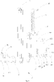
Fig. 1 is a perspective view of a hinge having a buffering effect according to an embodiment of the present disclosure. -
Fig. 2 is an exploded view of a hinge having a buffering effect according to an embodiment of the present disclosure. -
Fig. 3 is a sectional view of the hinge having the buffering effect inFig. 1 along line III-III. -
Fig. 4 is a perspective view of a first assembly of a hinge having a buffering effect according to an embodiment of the present disclosure. -
Fig. 5 is a perspective view of a stepped piece of a hinge having a buffering effect according to an embodiment of the present disclosure. -
Fig. 6 is a perspective view of a connecting piece of a hinge having a buffering effect according to an embodiment of the present disclosure. -
Fig. 7 is a perspective view of a connecting body of a hinge having a buffering effect according to an embodiment of the present disclosure. - Embodiments of the present disclosure will be described in detail and examples of the embodiments will be illustrated in the drawings, where same or similar reference numerals are used to indicate same or similar members or members with same or similar functions. The embodiments described herein with reference to drawings are explanatory, illustrative, and used to generally understand the present disclosure. The embodiments shall not be construed to limit the present disclosure.
- In the specification, it is to be understood that terms such as "central," "longitudinal," "lateral," "length," "width," "thickness," "upper," "lower," "front," "rear," "left," "right," "vertical," "horizontal," "top," "bottom," "inner," "outer," "clockwise," and "counterclockwise" should be construed to refer to the orientation as then described or as shown in the drawings under discussion. These relative terms are for convenience of description and do not require that the present disclosure be constructed or operated in a particular orientation. In addition, terms such as "first" and "second" are used herein for purposes of description and are not intended to indicate or imply relative importance or significance or to imply the number of indicated technical features. Thus, the feature defined with "first" and "second" may comprise one or more of this feature. In the description of the present disclosure, "a plurality of' means two or more than two, unless specified otherwise.
- In the present specification, unless specified and defined otherwise, it is to be illustrated that the terms "mounted," "connected," "coupled" and the like are used broadly, and may be, for example, fixed connections, detachable connections, or integral connections; may also be mechanical or electrical connections; may also be direct connections or indirect connections via intervening structures; may also be inner communications or interaction relation of two elements, which can be understood by those skilled in the art according to specific situations.
- In the present disclosure, unless specified or limited otherwise, a structure in which a first feature is "on" or "below" a second feature may include an embodiment in which the first feature is in direct contact with the second feature, and may also include an embodiment in which the first feature and the second feature are not in direct contact with each other, but are contacted via an additional feature formed therebetween. Furthermore, a first feature "on," "above," or "on top of' a second feature may include an embodiment in which the first feature is right or obliquely "on," "above," or "on top of' the second feature, or just means that the first feature is at a height higher than that of the second feature; while a first feature "below," "under," or "on bottom of' a second feature may include an embodiment in which the first feature is right or obliquely "below," "under," or "on bottom of' the second feature, or just means that the first feature is at a height lower than that of the second feature.
- Various embodiments and examples are provided in the following description to implement different structures of the present disclosure. In order to simplify the present disclosure, certain elements and settings will be described. However, these elements and settings are only by way of example and are not intended to limit the present disclosure. In addition, reference numerals may be repeated in different examples in the present disclosure. This repeating is for the purpose of simplification and clarity and does not refer to relations between different embodiments and/or settings. Furthermore, examples of different processes and materials are provided in the present disclosure. However, it would be appreciated by those skilled in the art that other processes and/or materials may be also applied.
- Referring to
Fig. 1 to Fig. 3 , ahinge 10 having a buffering effect according to a preferable embodiment of the present disclosure includes afirst assembly 12, asecond assembly 14, amain spring 16, a connectingpiece 18, a damper assembly 20, a connectingassembly 22 and a lockingspring 24. Thefirst assembly 12 and thesecond assembly 14 are configured to be fixed to a device body and a drop-down door respectively and are rotatably connected by means of a firstrotary shaft 142, so that the drop-down door may be rotatably pulled downwards with respect to the device body. Thefirst assembly 12 is configured to be a rectangular casing and includes afirst end 120 rotatably connected with thesecond assembly 14 and asecond end 122 opposite to thefirst end 120. Thefirst assembly 12 is provided with afirst guiding groove 124 adjacent to thefirst end 120, and thesecond assembly 14 includes a cam portion 140. Themain spring 16 is disposed in thefirst assembly 12 and has a first end fixedly connected with thesecond end 122. The connectingpiece 18 is disposed in thefirst assembly 12. The connectingpiece 18 is connected with a second end of themain spring 16 and further rotatably connected with thesecond assembly 14 by means of a secondrotary shaft 26. The connectingpiece 18 is provided with anupper cover 180 so as to be fitted with thefirst assembly 12 to form acavity 182, and the connectingpiece 18 is provided with asecond guiding groove 184. The damper assembly 20 includes adamper body 200, an extending and retractingrod 202, a return spring 204, aposition limiting piece 206 and a thirdrotary shaft 208. Thedamper body 200 is located in thecavity 182 and provided with athird guiding groove 20a. The extending and retractingrod 202 extends from thedamper body 200 towards thesecond assembly 14. The return spring 204 is fitted over the extending and retractingrod 202 and disposed in thedamper body 200. Theposition limiting piece 206 is fixed in thefirst assembly 12, and theposition limiting piece 206 is penetrated by the extending and retractingrod 202. The thirdrotary shaft 208 connects thedamper body 200 with the connectingpiece 18. The thirdrotary shaft 208 is rotatably and slidably disposed in thesecond guiding groove 184 and thethird guiding groove 20a. The connectingassembly 22 is disposed between thesecond assembly 14 and the extending and retractingrod 202. The connectingassembly 22 is fixedly connected with the extending and retractingrod 202. The connectingassembly 22 is connected with the connectingpiece 18 by means of a fourthrotary shaft 28. The fourthrotary shaft 28 is rotatably and slidably disposed in thefirst guiding groove 124. The connectingassembly 22 includes a drivenpulley 220. The lockingspring 24 is fitted over the extending and retractingrod 202 and disposed between theposition limiting piece 206 and the connectingassembly 22, so that the drivenpulley 220 may keep rotatable contact with the cam portion 140. The cam portion 140 has a balanced stage, a critical stage and a buffered-closing stage in a rotation process of thesecond assembly 14 from a position where a largest opening angle is formed between thefirst assembly 12 and thesecond assembly 14 to thefirst assembly 12, and the cam portion 140 is successively fitted with the drivenpulley 220 in these stages. In the balanced stage, the lockingspring 24 is in a compressed state and changes to a reset state, the return spring 204 is in a natural state, thedamper body 200 is motionless in thecavity 182, themain spring 16 is in a stretched state and changes to a reset state, and a tensioning force produced by themain spring 16 is balanced with a load weight of thehinge 10. In the critical stage, the lockingspring 24 is in the compressed state and changes to the reset state, the return spring 204 is in the natural state, thedamper body 200 slides in thecavity 182 in a direction towards thesecond end 122, themain spring 16 is in the stretched state, and the tensioning force produced by themain spring 16 is larger than the load weight of thehinge 10. In the buffered-closing stage, the lockingspring 24 is in the compressed state and changes to the reset state, the return spring 204 is in the natural state, the extending and retractingrod 202 is retracted into thedamper body 200, themain spring 16 is in the stretched state and changes to the reset state, the tensioning force produced by themain spring 16 is larger than the load weight of thehinge 10 and thedamper body 200 has a reverse buffering effect. - In the hinge according to preferable embodiments of the present disclosure, as the
main spring 16 is adopted, it is possible to balance a weight of the drop-down door when pulling the drop-down door downwards, thus realizing stable opening and stable closing. In addition, as the lockingspring 24 and the damper assembly 20 are adopted, the drop-down door may be closed automatically and slowly, thus improving a using experience of a user. - Referring to
Fig. 4 , in the present embodiment, thefirst assembly 12 has a substantially rectangular shape. Thefirst assembly 12 includes thefirst end 120 and thesecond end 122 opposite to thefirst end 120. Thefirst assembly 12 further includes abottom plate 126 andside walls 128 extending upwards from two sides of thebottom plate 126 respectively. Thefirst guiding groove 124 is formed in each of the twoside walls 128 and has an arc shape, and extends substantially along a length direction of thefirst assembly 12. Thefirst guiding groove 124 includes afirst end point 1240 and asecond end point 1242 opposite to thefirst end point 1240. - Thus, it is possible to coordinate a moving track of the connecting
assembly 22 by adopting the arc-shaped first guidinggroove 124. - Referring to
Fig. 5 , specifically, themain spring 16, the connectingpiece 18, the damper assembly 20, the connectingassembly 22 and the lockingspring 24 are accommodated in thefirst assembly 12. Thefirst assembly 12 has agroove 128a in thebottom plate 126 adjacent to thefirst end 120, and thegroove 128a is parallel with an axial direction of thefirst assembly 12. Thegroove 128a has a U shape. Thefirst assembly 12 and thesecond assembly 14 are connected by means of the firstrotary shaft 142 at thefirst end 120. Thefirst assembly 12 is configured to rotate relative to thesecond assembly 14 around the firstrotary shaft 142 and also to drive the connectingpiece 18 to move synchronously. Thesecond assembly 14 is configured to swing in thegroove 128a relative to thefirst assembly 12. Thefirst assembly 12 is connected with a fifthrotary shaft 30 at thesecond end 122, and the fifthrotary shaft 30 is parallel with the firstrotary shaft 142. A tail end of the connectingpiece 18 away from thefirst end 120 is connected with a connectingshaft 32 parallel with the fifthrotary shaft 30. Themain spring 16 is connected with the fifthrotary shaft 30 and the connectingshaft 32. Thesecond assembly 14 is connected to a steppedpiece 36 by means of a sixthrotary shaft 34 parallel with the secondrotary shaft 26. The steppedpiece 36 includes afifth side 360 and asixth side 362 opposite to thefifth side 360. Thesecond assembly 14 is located between thefifth side 360 and thesixth side 362. The sixthrotary shaft 34 passes through thefifth side 360 and thesixth side 362 to be connected with thesecond assembly 14. Thefifth side 360 and thesixth side 362 are connected and joint by means of afirst step surface 364. Above thefirst step surface 364, thefifth side 360 and thesixth side 362 are connected and joint by means of asecond step surface 366. The steppedpiece 36 has a U shape, and thefirst step surface 364 and thesecond step surface 366 forms a stepped shape. Thefirst step surface 364 is configured to be wedged in thegroove 128a, and thesecond step surface 366 is configured to abut against thebottom plate 126 of thefirst assembly 12. - Referring to
Fig. 6 , in the present embodiment, the connectingpiece 18 is accommodated in thefirst assembly 12 and includes twoside sheets 186 and theupper cover 180 jointed to the twoside sheets 186. The twoside sheets 186 are tightly attached to the twoside walls 128 of thefirst assembly 12 respectively. Theupper cover 180 is parallel with thebottom plate 126 of thefirst assembly 12, theupper cover 180 is fitted with thefirst assembly 12 to form thecavity 182, and thedamper body 200 is configured to slide in thecavity 182. Thesecond assembly 14 is configured to have a sheet shape, located in the connectingpiece 18, and extends into thegroove 128a. The connectingpiece 18 and thesecond assembly 14 are connected by means of the secondrotary shaft 26 parallel with the firstrotary shaft 142. The connectingpiece 18 connects themain spring 16 with thesecond assembly 14, and a connecting point of the connectingpiece 18 and thesecond assembly 14 deviates from the firstrotary shaft 142 of thesecond assembly 14, so that thesecond assembly 14 may drive the connectingpiece 18 to move when thesecond assembly 14 rotates relative to thefirst assembly 12, so as to stretch themain spring 16. - Thus, the connecting
piece 18 provided with theupper cover 180 performs a position limitation to thedamper body 200. - In the present embodiment, the
cavity 182 has a rectangular shape, thedamper body 200 has a cylindrical shape, and shapes of thedamper body 200 and thecavity 182 are matched with each other so as to enable thedamper body 200 to slide in thecavity 182. - In the present embodiment, the
position limiting piece 206 has an L shape and includes abottom sheet 206a fixedly connected with thebottom plate 126 and ablocking sheet 206b extending upwards from thebottom sheet 206a, and the blockingsheet 206b is penetrated by the extending and retractingrod 202. - Thus, the
position limiting piece 206 performs a position limitation to thedamper body 200. The connectingpiece 18, theposition limiting piece 206 and the thirdrotary shaft 208 cooperate to define a moving range of thedamper body 200, thus proving a simple structure and convenient assembling and disassembling. - Specifically, the connecting
piece 18, theposition limiting piece 206 and the thirdrotary shaft 208 disposed in thesecond guiding groove 184 and thethird guiding groove 20a define a sliding travel of thedamper body 200. A position limitation of thedamper body 200 is performed by means of the connectingpiece 18, theposition limiting piece 206 and the thirdrotary shaft 208. Thedamper body 200 is configured to move in an axial length range of thethird guiding groove 20a in a linear and reciprocating manner. When the drop-down door is opened to a largest angle, the thirdrotary shaft 208 is located at a rightmost end of thethird guiding groove 20a. The extending and retractingrod 202 extends from thedamper body 200, and a tail end of the extending and retractingrod 202 is fixed with the connectingassembly 22 by means of a threadedpin 38. Thedamper body 200 is configured as a hydraulic damper. - Referring to
Fig. 7 , in the present embodiment, the connectingassembly 22 includes a connectingbody 222 and the drivenpulley 220 disposed to the connectingbody 222, and the connectingbody 222 is fixedly connected with the extending and retractingrod 202. The connectingbody 222 and the connectingpiece 18 are connected by means of the fourthrotary shaft 28 slidably disposed in thefirst guiding groove 124. The connectingbody 222 is provided with a fixedshaft 2220, the drivenpulley 220 has an annular shape and is fitted over the fixedshaft 2220, and the drivenpulley 220 keeps contacting the cam portion 140. The drivenpulley 220 may rotate with treating the fourthrotary shaft 28 as its axis, and thus it is guaranteed that the drivenpulley 220 keeps contacting the cam portion 140 constantly. The connectingbody 222 includes athird side 2222, afourth side 2224 opposite to thethird side 2222, and ablocking surface 2226 perpendicular to thethird side 2222 and thefourth side 2224 and located between thethird side 2222 and thefourth side 2224. The fixedshaft 2220 is formed between thethird side 2222 and thefourth side 2224. The blockingsurface 2226 has ahole 2228 in a center thereof, and thehole 2228 is configured to be fitted with the extending and retractingrod 202. The extending and retractingrod 202 rightly passes through thehole 2228, and the threadedpin 38 mounted to the extending and retractingrod 202 blocks theblocking surface 2226. The connectingbody 222 is formed integrally, and the cam portion 140 has concave and convex portions having various contacts with the drivenpulley 220. - Accordingly, the connecting
piece 18 and the connectingassembly 22 are connected by means of the fourthrotary shaft 28 and the fourthrotary shaft 28 is slidably disposed in thefirst guiding groove 124. The connectingpiece 18 drives the fourthrotary shaft 28 to slide in thefirst guiding groove 124. - The
first assembly 12 is disposed to the drop-down door, and thesecond assembly 14 is disposed to the device body. When thehinge 10 operates, a position of thesecond assembly 14 is constant, and thefirst assembly 12 may rotate around the firstrotary shaft 142 by a certain angle and drive the connectingpiece 18 connected to thesecond assembly 14 to move synchronously, so that themain spring 16 connected to the connectingpiece 18 may be stretched. Under actions of themain spring 16 and the damper assembly 20, the drop-down door may be closed automatically and slowly. - Specifically, the balanced stage represents that the
hinge 10 transfers from a position n1 to a position n2, the critical stage represents that thehinge 10 transfers from the position n2 to a position n3, and the buffered-closing stage represents that thehinge 10 transfers from the position n3 to a position n4. When thesecond assembly 14 is located at the position n1 with respect to thefirst assembly 12, thehinge 10 has the largest opening angle, and the drop-down door is opened to the largest angle. When thesecond assembly 14 is located at the position n4 with respect to thefirst assembly 12, thehinge 10 has a smallest opening angle and a door body is in a closed state. - When the
second assembly 14 is located at the position n1 with respect to thefirst assembly 12, the connectingpiece 18 drives the fourthrotary shaft 28 to reach thefirst end point 1240, the thirdrotary shaft 208 is located at a right end of thethird guiding groove 20a, themain spring 16 is stretched by the connectingpiece 18 so as to be in the stretched state, and the tensioning force of themain spring 16 is balanced with the load weight of thehinge 10. When thehinge 10 operates in an angle a, i.e. in the balanced stage from the position n1 to the position n2, as the tensioning force of themain spring 16 is balanced with the load weight of thehinge 10, the drop-down door may be motionless at any position in this range, in which case an external force of human is required for closing the drop-down door. - When the
second assembly 14 is located at the position n2 with respect to thefirst assembly 12, the tensioning force of themain spring 16 is larger than the load weight of thehinge 10. When thehinge 10 operates in an angle b, i.e. in the critical stage from the position n2 to the position n3, the connectingpiece 18 connected with themain spring 16 slides in a direction towards themain spring 16, and hence thedamper body 200 slides, so that the thirdrotary shaft 208 slides towards a leftmost end of thethird guiding groove 20a, i.e. thehinge 10 may automatically drive the drop-down door to rotate rapidly in a closing direction, in which case the drop-down door may be closed automatically without the external force. - When the
second assembly 14 is located at the position n3 with respect to thefirst assembly 12, the tensioning force of themain spring 16 is larger than the load weight of thehinge 10, the thirdrotary shaft 208 is located at the leftmost end of thethird guiding groove 20a, and the return spring 204 restores to the natural state from the compressed state. When thehinge 10 operates in an angle c, i.e. in the buffered-closing stage from the position n3 to the position n4, the connectingpiece 18 connected with themain spring 16 continues sliding in the direction towards themain spring 16, the extending and retractingrod 202 starts to be retracted into thedamper body 200, and hence thedamper body 200 generates a reverse buffering force, so as to slow down a rotation speed of the door body driven by thehinge 10, so that the drop-down door rotates in a slow and uniform speed, in which case the drop-down door may be closed automatically in a gentle manner, instead of being rebounded rapidly. - When the
second assembly 14 is located at the position n4 with respect to thefirst assembly 12, thehinge 10 has the smallest opening angle, and the door body is in the closed state. In this case, themain spring 16, the lockingspring 24 and the return spring 204 are all in the natural state. - When the
hinge 10 is opened from the position n4 to any position in a range of the angle C under an action of an external force (which is usually applied by human), thedamper body 200 slides in a direction towards thesecond assembly 14, and the return spring 204 applies a resistance force to thedamper body 200 to allow a hydraulic oil in thedamper body 200 to reset. When the external force is withdrawn, as the tensioning force of themain spring 16 is larger than the load weight of thehinge 10, the drop-down door rotates in a direction towards themain spring 16, that is, the drop-down door will still be closed in a slow and uniform speed, i.e. thehinge 10 will still return to the position n4. - In the present embodiment, corresponding to the balanced stage, the
hinge 10 is located at a position between the position n1 and the position n2, in which case the tensioning force produced by themain spring 16 is balanced with the load weight of thehinge 10, and thus the drop-down door may be stopped at any position in a range of the angle a. Corresponding to the balanced stage, the drop-down door is configured to rotate by an angle of 50°-70°, that is, the range of the angel a is 50°-70°. - In the present embodiment, corresponding to the critical stage, the
hinge 10 is located at a position between the position n2 and the position n3, in which case the tensioning force produced by themain spring 16 is larger than the load weight of thehinge 10, and thus the hinge may rotate from the position n2 to the position n3 rapidly in a range of the angle b. Corresponding to the critical stage, the drop-down door is configured to rotate by an angle of 10°-15°, that is, the range of the angel b is 10°-15°. - In the present embodiment, corresponding to the buffered-closing stage, the
hinge 10 is located at a position between the position n3 and the position n4, in which case the tensioning force produced by themain spring 16 is larger than the load weight of thehinge 10, and thus the hinge may rotate from the position n3 to the position n4 slowly in the range of the angle c. Corresponding to the buffered-closing stage, the drop-down door is configured to rotate by an angle of 10°-25°, that is, the range of the angel c is 10°-25°. - Thus, the drop-down door may be closed automatically and slowly in a designed angle range, thus improving the using experience of the user.
- Certainly, numerical values above are provided as examples, so as to aid in illustrating a manner in which the automatic and slow closing of the drop-down door in a certain opening and closing angle is realized by means of the
hinge 10, but are not used to limit the present disclosure. - A device in a preferable embodiment of the present disclosure includes a device body and a drop-down door. The device includes the
above hinge 10. Thefirst assembly 12 is fixedly disposed to the drop-down door, and thesecond assembly 14 is fixedly disposed to the device body. Optionally, the device is an oven. Certainly, the oven only serves as an example, but is not used to limit the present disclosure. Thus, the drop-down door of the device may be closed automatically and slowly, which prevents the drop-down door of the device from being damaged due to a rapid closing caused by overexertion. - Reference throughout this specification to "an embodiment," "some embodiments," "an illustrative embodiment" "an example," "a specific example," or "some examples," means that a particular feature, structure, material, or characteristic described in connection with the embodiment or example is included in at least one embodiment or example of the present disclosure. Thus, the appearances of the phrases in various places throughout this specification are not necessarily referring to the same embodiment or example of the present disclosure. Furthermore, the particular features, structures, materials, or characteristics may be combined in any suitable manner in one or more embodiments or examples.
- Although embodiments of the present disclosure have been shown and illustrated, it shall be understood by those skilled in the art that various changes, modifications, alternatives and variants without departing from the principle and intention of the present disclosure are acceptable. The scope of the present disclosure is defined by the claims .
Claims (11)
- A hinge (10) having a buffering effect, comprising:a first assembly (12) and a second assembly (14) rotatably connected by means of a first rotary shaft (142), the first assembly (12) comprising a first end (120) rotatably connected with the second assembly (14) and a second end (122) opposite to the first end (120), the first assembly (12) having a first guiding groove (124) adjacent to the first end (120), the second assembly (14) being provided with a cam portion (140);a main spring (16) disposed in the first assembly (12), a first end of the main spring (16) being fixedly connected with the second end (122) of the first assembly (12);a connecting piece (18) disposed in the first assembly (12), connected with a second end of the main spring (16) and further rotatably connected with the second assembly (14) by means of a second rotary shaft (26), the connecting piece (18) being provided with an upper cover (180) so as to be fitted with the first assembly (12) to form a cavity (182), the connecting piece (18) having a second guiding groove (184);a damper assembly (20), comprising:a damper body (200) located in the cavity (182) and having a third guiding groove (20a);an extending and retracting rod (202) extending from the damper body (200) towards the second assembly (14);a return spring (204) fitted over the extending and retracting rod (202) and disposed in the damper body (200);a position limiting piece (206) fixed in the first assembly (12) and penetrated by the extending and retracting rod (202); anda third rotary shaft (208) connecting the damper body (200) with the connecting piece (18);a connecting assembly (22) disposed between the second assembly (14) and the extending and retracting rod (202), the connecting assembly (22) being fixedly connected with the extending and retracting rod (202), the connecting assembly (22) being connected with the connecting piece (18) by means of a fourth rotary shaft (28), the fourth rotary shaft (28) being rotatably and slidably disposed in the first guiding groove (124), the connecting assembly (22) comprising a driven pulley (220); anda locking spring (24) fitted over the extending and retracting rod (202) and disposed between the position limiting piece (206) and the connecting assembly (22) so as to allow the driven pulley (220) to keep rotatable contact with the cam portion (140),wherein the cam portion (140) has a balanced stage, a critical stage and a buffered-closing stage in a rotation process of the second assembly (14) from a position where a largest opening angle is formed between the first assembly (12) and the second assembly (14) to the first assembly (12), and the cam portion (140) is successively fitted with the driven pulley (220) in these stages;in the balanced stage, the locking spring (24) is in a compressed state and changes to a reset state, the return spring (204) is in a natural state, the damper body (200) is motionless in the cavity (182), the main spring (16) is in a stretched state and changes to a reset state, and a tensioning force produced by the main spring (16) is balanced with a load weight of the hinge (10);in the critical stage, the locking spring (24) is in the compressed state and changing to the reset state, the return spring (204) is in the natural state, the damper body (200) slides in the cavity (182) in a direction towards the second end (122), the main spring (16) is in the stretched state, and the tensioning force produced by the main spring (16) is larger than the load weight of the hinge (10);in the buffered-closing stage, the locking spring (24) is in the compressed state and changes to the reset state, the return spring (204) is in the natural state, the extending and retracting rod (202) is retracted into the damper body (200), the main spring (16) is in the stretched state and changes to the reset state, the tensioning force produced by the main spring (16) is larger than the load weight of the hinge (10) and the damper body (200) generates a reverse buffering effectcharacterized in that
the third rotary shaft (208) connecting the damper body (200) with the connecting piece (18) is rotatably and slidably disposed in the second guiding groove (184) and the third guiding groove (20a). - The hinge (10) having the buffering effect according to claim 1, wherein the first assembly (12) comprises a bottom plate (126) and side walls (128) extending upwards from two sides of the bottom plate (126), and the first guiding groove (124) is formed in each of the two side walls (128) and has an arc shape.
- The hinge (10) having the buffering effect according to claim 2, wherein the connecting piece (18) comprises two side sheets (186) tightly attached to the side walls (128) respectively and the upper cover (180) joint to the two side sheets (186).
- The hinge (10) having the buffering effect according to claim 1, wherein the cavity (182) has a rectangular shape, the damper body (200) has a cylindrical shape, and shapes of the damper body (200) and the cavity (182) are matched with each other so as to allow the damper body (200) to slide in the cavity (182).
- The hinge (10) having the buffering effect according to claim 2, wherein the position limiting piece (206) has an L shape, the position limiting piece (206) comprises a bottom sheet (206a) fixedly connected with the bottom plate (126) and a blocking sheet (206b) extending upwards from the bottom sheet (206a), and the blocking sheet (206b) is penetrated by the extending and retracting rod (202).
- The hinge (10) having the buffering effect according to claim 1, wherein the connecting assembly (22) comprises a connecting body (222) fixedly connected with the extending and retracting rod (202) and the driven pulley (220) disposed to the connecting body (222), the connecting body (222) and the connecting piece (18) are connected by means of the fourth rotary shaft (28) slidably disposed in the first guiding groove (124), the connecting body (222) is provided with a fixed shaft (2220), the driven pulley (220) has an annular shape and is fitted over the fixed shaft (2220), and the driven pulley (220) keeps being rotatably connected with the cam portion (140).
- The hinge (10) having the buffering effect according to any one of claims 1 to 6, wherein corresponding to the balanced stage, a drop-down door is configured to rotate by an angle (a) of 50°-70°.
- The hinge (10) having the buffering effect according to any one of claims 1 to 6, wherein corresponding to the critical stage, a drop-down door is configured to rotate by an angle (b) 10°-15°.
- The hinge (10) having the buffering effect according to any one of claims 1 to 6, wherein corresponding to the buffered-closing stage, a drop-down door is configured to rotate by an angle (c) of 10°-25°.
- The hinge (10) having the buffering effect according to claim 1, wherein the first assembly (12) is configured as a rectangular casing.
- A device, comprising a device body, a drop-down door and a hinge (10) configured for the device according to any one of claims 1 to 10, the first assembly (12) and the second assembly (14) of the hinge (10) are configured to be fixed to the device body and the drop-down door respectively and are rotatably connected by means of a first rotary shaft (142), so that the drop-down door is configured to be rotatably pulled downwards with respect to the device body.
Applications Claiming Priority (2)
| Application Number | Priority Date | Filing Date | Title |
|---|---|---|---|
| CN201510066884.5A CN104727683B (en) | 2015-02-06 | 2015-02-06 | There is the hinge of buffering effect and there is the device of described hinge |
| PCT/CN2015/077724 WO2016123871A1 (en) | 2015-02-06 | 2015-04-28 | Hinge providing cushioning effect and apparatus provided with the hinge |
Publications (3)
| Publication Number | Publication Date |
|---|---|
| EP3255235A1 EP3255235A1 (en) | 2017-12-13 |
| EP3255235A4 EP3255235A4 (en) | 2018-11-21 |
| EP3255235B1 true EP3255235B1 (en) | 2022-06-22 |
Family
ID=53452031
Family Applications (1)
| Application Number | Title | Priority Date | Filing Date |
|---|---|---|---|
| EP15880826.1A Active EP3255235B1 (en) | 2015-02-06 | 2015-04-28 | Hinge providing cushioning effect and apparatus provided with the hinge |
Country Status (4)
| Country | Link |
|---|---|
| EP (1) | EP3255235B1 (en) |
| CN (1) | CN104727683B (en) |
| RU (1) | RU2656844C1 (en) |
| WO (1) | WO2016123871A1 (en) |
Families Citing this family (10)
| Publication number | Priority date | Publication date | Assignee | Title |
|---|---|---|---|---|
| CN106724741B (en) * | 2016-12-02 | 2018-11-30 | 广东美的厨房电器制造有限公司 | cooking appliance |
| CN108203870B (en) * | 2016-12-16 | 2021-06-01 | 合肥海尔洗衣机有限公司 | Washing machine tray parts and washing machine |
| KR102013025B1 (en) * | 2017-04-05 | 2019-08-21 | 서원코리아 주식회사 | Door hinge |
| CN107419986B (en) * | 2017-08-28 | 2023-05-09 | 珠海格力电器股份有限公司 | Damping hinge and device provided with same |
| CN108173141A (en) * | 2018-02-05 | 2018-06-15 | 安徽开美电气有限公司 | A kind of low-tension switch cabinet with damping base |
| CN108332497A (en) * | 2018-04-04 | 2018-07-27 | 安徽安缆模具有限公司 | It is a kind of can automatic pick refrigerator door hinge chain case assembly |
| CN111396446B (en) * | 2020-04-02 | 2024-10-18 | 上海杰邦塑料五金制品有限公司 | Hinge device |
| CN113099653B (en) * | 2021-03-26 | 2023-02-28 | 山东英信计算机技术有限公司 | An electronic device and its connection module |
| IT202100023870A1 (en) * | 2021-09-16 | 2023-03-16 | C M I Cerniere Mecc Industriali Srl | ZIPPER WITH ELASTIC RETAINER |
| CN118125179B (en) * | 2023-12-27 | 2024-10-25 | 诸暨市舒亭纺织有限公司 | Flattening equipment and method for cloth production |
Family Cites Families (11)
| Publication number | Priority date | Publication date | Assignee | Title |
|---|---|---|---|---|
| KR100450581B1 (en) * | 2002-02-28 | 2004-09-30 | 삼성전자주식회사 | Hinge device and portable terminal therewith |
| TWM254061U (en) * | 2004-02-06 | 2004-12-21 | Hon Hai Prec Ind Co Ltd | Hinge structure |
| ATE521776T1 (en) * | 2009-02-13 | 2011-09-15 | Electrolux Home Prod Corp | OVEN DOOR OPENING AND CLOSING DEVICE |
| CN201695837U (en) * | 2010-05-11 | 2011-01-05 | 李炎平 | an oven hinge |
| KR101193477B1 (en) * | 2010-08-27 | 2012-10-24 | 주식회사 이피텍 | Hinge device for oven |
| GB201116913D0 (en) * | 2011-09-30 | 2011-11-16 | Chung Chow | Damped self-centreing hinge |
| WO2012168748A1 (en) * | 2011-06-08 | 2012-12-13 | Faringosi Hinges S.R.L. | Hinges provided with elastic means and dampener |
| GB2504917B (en) * | 2012-01-27 | 2015-06-03 | Chung Chow | Damped self-centering hinge |
| SI24023A (en) * | 2012-03-06 | 2013-09-30 | Turna D.O.O. | A device and a method for controlled door closing |
| PL2664737T3 (en) * | 2012-05-15 | 2016-05-31 | Atasan Metal Sanayi Ve Ticaret Ltd Sirketi | A door hinge |
| CN204126434U (en) * | 2014-08-06 | 2015-01-28 | 胡国衡 | A kind of baking box damp hinge |
-
2015
- 2015-02-06 CN CN201510066884.5A patent/CN104727683B/en active Active
- 2015-04-28 RU RU2017131230A patent/RU2656844C1/en active
- 2015-04-28 WO PCT/CN2015/077724 patent/WO2016123871A1/en not_active Ceased
- 2015-04-28 EP EP15880826.1A patent/EP3255235B1/en active Active
Also Published As
| Publication number | Publication date |
|---|---|
| EP3255235A1 (en) | 2017-12-13 |
| WO2016123871A1 (en) | 2016-08-11 |
| EP3255235A4 (en) | 2018-11-21 |
| RU2656844C1 (en) | 2018-06-06 |
| CN104727683B (en) | 2016-12-14 |
| CN104727683A (en) | 2015-06-24 |
Similar Documents
| Publication | Publication Date | Title |
|---|---|---|
| EP3255235A1 (en) | Hinge providing cushioning effect and apparatus provided with the hinge | |
| EP3255234B1 (en) | Hinge having damping effect, and apparatus having said hinge | |
| CN108412356B (en) | Hinge of two-section force quick-dismantling damping mounting structure | |
| CN107989503B (en) | Buffering hinge | |
| US10145163B2 (en) | Home appliance having movable handle | |
| CN206192035U (en) | A door body is bit architecture and refrigeration plant only for refrigeration plant | |
| WO2018149156A1 (en) | American damping hydraulic hinge | |
| WO2018103246A1 (en) | Hinge mechanism and furniture | |
| CN103470121B (en) | With the door hinge of pooling feature | |
| WO2017193420A1 (en) | Buffering hinge for thick door plate | |
| CN104165009B (en) | A kind of oven door can optional position stop oven hinge | |
| CN211342335U (en) | Self-suction switch window type opening and closing mechanism | |
| CN211691960U (en) | Large-opening high-load hinge | |
| CN112922481A (en) | Door hinge buffer and contain its door hinge | |
| CN204728878U (en) | A kind of hinge with step-less adjustment bumper angle | |
| CN204436123U (en) | There is the hinge of buffering effect and there is the device of described hinge | |
| CN110847741A (en) | Self-suction switch window type opening and closing mechanism | |
| CN204850842U (en) | Hinge elastic construction of furniture folding door | |
| CN215565207U (en) | Door hinge buffer and contain its door hinge | |
| CN113356708A (en) | Hinge and refrigeration equipment | |
| KR100903375B1 (en) | Hinge assembly for the door | |
| CN207270120U (en) | Multifunctional filing cabinet | |
| CN104712208B (en) | There is the hinge of buffering effect and there is the device of described hinge | |
| CN207879122U (en) | A kind of adjustable oven hinge in buffering direction | |
| CA2465459A1 (en) | Cabinet door support mechanism |
Legal Events
| Date | Code | Title | Description |
|---|---|---|---|
| STAA | Information on the status of an ep patent application or granted ep patent |
Free format text: STATUS: THE INTERNATIONAL PUBLICATION HAS BEEN MADE |
|
| PUAI | Public reference made under article 153(3) epc to a published international application that has entered the european phase |
Free format text: ORIGINAL CODE: 0009012 |
|
| STAA | Information on the status of an ep patent application or granted ep patent |
Free format text: STATUS: REQUEST FOR EXAMINATION WAS MADE |
|
| 17P | Request for examination filed |
Effective date: 20170906 |
|
| AK | Designated contracting states |
Kind code of ref document: A1 Designated state(s): AL AT BE BG CH CY CZ DE DK EE ES FI FR GB GR HR HU IE IS IT LI LT LU LV MC MK MT NL NO PL PT RO RS SE SI SK SM TR |
|
| AX | Request for extension of the european patent |
Extension state: BA ME |
|
| DAV | Request for validation of the european patent (deleted) | ||
| DAX | Request for extension of the european patent (deleted) | ||
| A4 | Supplementary search report drawn up and despatched |
Effective date: 20181018 |
|
| RIC1 | Information provided on ipc code assigned before grant |
Ipc: E05F 3/20 20060101AFI20181012BHEP Ipc: E05F 1/12 20060101ALI20181012BHEP |
|
| GRAP | Despatch of communication of intention to grant a patent |
Free format text: ORIGINAL CODE: EPIDOSNIGR1 |
|
| STAA | Information on the status of an ep patent application or granted ep patent |
Free format text: STATUS: GRANT OF PATENT IS INTENDED |
|
| INTG | Intention to grant announced |
Effective date: 20211203 |
|
| GRAS | Grant fee paid |
Free format text: ORIGINAL CODE: EPIDOSNIGR3 |
|
| GRAJ | Information related to disapproval of communication of intention to grant by the applicant or resumption of examination proceedings by the epo deleted |
Free format text: ORIGINAL CODE: EPIDOSDIGR1 |
|
| GRAL | Information related to payment of fee for publishing/printing deleted |
Free format text: ORIGINAL CODE: EPIDOSDIGR3 |
|
| STAA | Information on the status of an ep patent application or granted ep patent |
Free format text: STATUS: REQUEST FOR EXAMINATION WAS MADE |
|
| GRAP | Despatch of communication of intention to grant a patent |
Free format text: ORIGINAL CODE: EPIDOSNIGR1 |
|
| STAA | Information on the status of an ep patent application or granted ep patent |
Free format text: STATUS: GRANT OF PATENT IS INTENDED |
|
| INTC | Intention to grant announced (deleted) | ||
| GRAS | Grant fee paid |
Free format text: ORIGINAL CODE: EPIDOSNIGR3 |
|
| INTG | Intention to grant announced |
Effective date: 20220422 |
|
| GRAA | (expected) grant |
Free format text: ORIGINAL CODE: 0009210 |
|
| STAA | Information on the status of an ep patent application or granted ep patent |
Free format text: STATUS: THE PATENT HAS BEEN GRANTED |
|
| AK | Designated contracting states |
Kind code of ref document: B1 Designated state(s): AL AT BE BG CH CY CZ DE DK EE ES FI FR GB GR HR HU IE IS IT LI LT LU LV MC MK MT NL NO PL PT RO RS SE SI SK SM TR |
|
| REG | Reference to a national code |
Ref country code: GB Ref legal event code: FG4D |
|
| REG | Reference to a national code |
Ref country code: CH Ref legal event code: EP |
|
| REG | Reference to a national code |
Ref country code: DE Ref legal event code: R096 Ref document number: 602015079591 Country of ref document: DE |
|
| REG | Reference to a national code |
Ref country code: AT Ref legal event code: REF Ref document number: 1499879 Country of ref document: AT Kind code of ref document: T Effective date: 20220715 |
|
| REG | Reference to a national code |
Ref country code: IE Ref legal event code: FG4D |
|
| REG | Reference to a national code |
Ref country code: LT Ref legal event code: MG9D |
|
| REG | Reference to a national code |
Ref country code: NL Ref legal event code: MP Effective date: 20220622 |
|
| PG25 | Lapsed in a contracting state [announced via postgrant information from national office to epo] |
Ref country code: SE Free format text: LAPSE BECAUSE OF FAILURE TO SUBMIT A TRANSLATION OF THE DESCRIPTION OR TO PAY THE FEE WITHIN THE PRESCRIBED TIME-LIMIT Effective date: 20220622 Ref country code: NO Free format text: LAPSE BECAUSE OF FAILURE TO SUBMIT A TRANSLATION OF THE DESCRIPTION OR TO PAY THE FEE WITHIN THE PRESCRIBED TIME-LIMIT Effective date: 20220922 Ref country code: LT Free format text: LAPSE BECAUSE OF FAILURE TO SUBMIT A TRANSLATION OF THE DESCRIPTION OR TO PAY THE FEE WITHIN THE PRESCRIBED TIME-LIMIT Effective date: 20220622 Ref country code: HR Free format text: LAPSE BECAUSE OF FAILURE TO SUBMIT A TRANSLATION OF THE DESCRIPTION OR TO PAY THE FEE WITHIN THE PRESCRIBED TIME-LIMIT Effective date: 20220622 Ref country code: GR Free format text: LAPSE BECAUSE OF FAILURE TO SUBMIT A TRANSLATION OF THE DESCRIPTION OR TO PAY THE FEE WITHIN THE PRESCRIBED TIME-LIMIT Effective date: 20220923 Ref country code: FI Free format text: LAPSE BECAUSE OF FAILURE TO SUBMIT A TRANSLATION OF THE DESCRIPTION OR TO PAY THE FEE WITHIN THE PRESCRIBED TIME-LIMIT Effective date: 20220622 Ref country code: BG Free format text: LAPSE BECAUSE OF FAILURE TO SUBMIT A TRANSLATION OF THE DESCRIPTION OR TO PAY THE FEE WITHIN THE PRESCRIBED TIME-LIMIT Effective date: 20220922 |
|
| REG | Reference to a national code |
Ref country code: AT Ref legal event code: MK05 Ref document number: 1499879 Country of ref document: AT Kind code of ref document: T Effective date: 20220622 |
|
| PG25 | Lapsed in a contracting state [announced via postgrant information from national office to epo] |
Ref country code: RS Free format text: LAPSE BECAUSE OF FAILURE TO SUBMIT A TRANSLATION OF THE DESCRIPTION OR TO PAY THE FEE WITHIN THE PRESCRIBED TIME-LIMIT Effective date: 20220622 Ref country code: LV Free format text: LAPSE BECAUSE OF FAILURE TO SUBMIT A TRANSLATION OF THE DESCRIPTION OR TO PAY THE FEE WITHIN THE PRESCRIBED TIME-LIMIT Effective date: 20220622 |
|
| PG25 | Lapsed in a contracting state [announced via postgrant information from national office to epo] |
Ref country code: NL Free format text: LAPSE BECAUSE OF FAILURE TO SUBMIT A TRANSLATION OF THE DESCRIPTION OR TO PAY THE FEE WITHIN THE PRESCRIBED TIME-LIMIT Effective date: 20220622 |
|
| PG25 | Lapsed in a contracting state [announced via postgrant information from national office to epo] |
Ref country code: SM Free format text: LAPSE BECAUSE OF FAILURE TO SUBMIT A TRANSLATION OF THE DESCRIPTION OR TO PAY THE FEE WITHIN THE PRESCRIBED TIME-LIMIT Effective date: 20220622 Ref country code: SK Free format text: LAPSE BECAUSE OF FAILURE TO SUBMIT A TRANSLATION OF THE DESCRIPTION OR TO PAY THE FEE WITHIN THE PRESCRIBED TIME-LIMIT Effective date: 20220622 Ref country code: RO Free format text: LAPSE BECAUSE OF FAILURE TO SUBMIT A TRANSLATION OF THE DESCRIPTION OR TO PAY THE FEE WITHIN THE PRESCRIBED TIME-LIMIT Effective date: 20220622 Ref country code: PT Free format text: LAPSE BECAUSE OF FAILURE TO SUBMIT A TRANSLATION OF THE DESCRIPTION OR TO PAY THE FEE WITHIN THE PRESCRIBED TIME-LIMIT Effective date: 20221024 Ref country code: ES Free format text: LAPSE BECAUSE OF FAILURE TO SUBMIT A TRANSLATION OF THE DESCRIPTION OR TO PAY THE FEE WITHIN THE PRESCRIBED TIME-LIMIT Effective date: 20220622 Ref country code: EE Free format text: LAPSE BECAUSE OF FAILURE TO SUBMIT A TRANSLATION OF THE DESCRIPTION OR TO PAY THE FEE WITHIN THE PRESCRIBED TIME-LIMIT Effective date: 20220622 Ref country code: CZ Free format text: LAPSE BECAUSE OF FAILURE TO SUBMIT A TRANSLATION OF THE DESCRIPTION OR TO PAY THE FEE WITHIN THE PRESCRIBED TIME-LIMIT Effective date: 20220622 Ref country code: AT Free format text: LAPSE BECAUSE OF FAILURE TO SUBMIT A TRANSLATION OF THE DESCRIPTION OR TO PAY THE FEE WITHIN THE PRESCRIBED TIME-LIMIT Effective date: 20220622 |
|
| PG25 | Lapsed in a contracting state [announced via postgrant information from national office to epo] |
Ref country code: PL Free format text: LAPSE BECAUSE OF FAILURE TO SUBMIT A TRANSLATION OF THE DESCRIPTION OR TO PAY THE FEE WITHIN THE PRESCRIBED TIME-LIMIT Effective date: 20220622 Ref country code: IS Free format text: LAPSE BECAUSE OF FAILURE TO SUBMIT A TRANSLATION OF THE DESCRIPTION OR TO PAY THE FEE WITHIN THE PRESCRIBED TIME-LIMIT Effective date: 20221022 |
|
| REG | Reference to a national code |
Ref country code: DE Ref legal event code: R097 Ref document number: 602015079591 Country of ref document: DE |
|
| PG25 | Lapsed in a contracting state [announced via postgrant information from national office to epo] |
Ref country code: AL Free format text: LAPSE BECAUSE OF FAILURE TO SUBMIT A TRANSLATION OF THE DESCRIPTION OR TO PAY THE FEE WITHIN THE PRESCRIBED TIME-LIMIT Effective date: 20220622 |
|
| PG25 | Lapsed in a contracting state [announced via postgrant information from national office to epo] |
Ref country code: DK Free format text: LAPSE BECAUSE OF FAILURE TO SUBMIT A TRANSLATION OF THE DESCRIPTION OR TO PAY THE FEE WITHIN THE PRESCRIBED TIME-LIMIT Effective date: 20220622 |
|
| PLBE | No opposition filed within time limit |
Free format text: ORIGINAL CODE: 0009261 |
|
| STAA | Information on the status of an ep patent application or granted ep patent |
Free format text: STATUS: NO OPPOSITION FILED WITHIN TIME LIMIT |
|
| 26N | No opposition filed |
Effective date: 20230323 |
|
| P01 | Opt-out of the competence of the unified patent court (upc) registered |
Effective date: 20230526 |
|
| PG25 | Lapsed in a contracting state [announced via postgrant information from national office to epo] |
Ref country code: SI Free format text: LAPSE BECAUSE OF FAILURE TO SUBMIT A TRANSLATION OF THE DESCRIPTION OR TO PAY THE FEE WITHIN THE PRESCRIBED TIME-LIMIT Effective date: 20220622 |
|
| REG | Reference to a national code |
Ref country code: CH Ref legal event code: PL |
|
| PG25 | Lapsed in a contracting state [announced via postgrant information from national office to epo] |
Ref country code: LU Free format text: LAPSE BECAUSE OF NON-PAYMENT OF DUE FEES Effective date: 20230428 |
|
| REG | Reference to a national code |
Ref country code: BE Ref legal event code: MM Effective date: 20230430 |
|
| PG25 | Lapsed in a contracting state [announced via postgrant information from national office to epo] |
Ref country code: MC Free format text: LAPSE BECAUSE OF FAILURE TO SUBMIT A TRANSLATION OF THE DESCRIPTION OR TO PAY THE FEE WITHIN THE PRESCRIBED TIME-LIMIT Effective date: 20220622 |
|
| PG25 | Lapsed in a contracting state [announced via postgrant information from national office to epo] |
Ref country code: MC Free format text: LAPSE BECAUSE OF FAILURE TO SUBMIT A TRANSLATION OF THE DESCRIPTION OR TO PAY THE FEE WITHIN THE PRESCRIBED TIME-LIMIT Effective date: 20220622 Ref country code: LI Free format text: LAPSE BECAUSE OF NON-PAYMENT OF DUE FEES Effective date: 20230430 Ref country code: CH Free format text: LAPSE BECAUSE OF NON-PAYMENT OF DUE FEES Effective date: 20230430 |
|
| REG | Reference to a national code |
Ref country code: IE Ref legal event code: MM4A |
|
| PG25 | Lapsed in a contracting state [announced via postgrant information from national office to epo] |
Ref country code: BE Free format text: LAPSE BECAUSE OF NON-PAYMENT OF DUE FEES Effective date: 20230430 |
|
| PG25 | Lapsed in a contracting state [announced via postgrant information from national office to epo] |
Ref country code: IE Free format text: LAPSE BECAUSE OF NON-PAYMENT OF DUE FEES Effective date: 20230428 |
|
| PG25 | Lapsed in a contracting state [announced via postgrant information from national office to epo] |
Ref country code: IE Free format text: LAPSE BECAUSE OF NON-PAYMENT OF DUE FEES Effective date: 20230428 |
|
| PG25 | Lapsed in a contracting state [announced via postgrant information from national office to epo] |
Ref country code: BG Free format text: LAPSE BECAUSE OF FAILURE TO SUBMIT A TRANSLATION OF THE DESCRIPTION OR TO PAY THE FEE WITHIN THE PRESCRIBED TIME-LIMIT Effective date: 20220622 |
|
| PG25 | Lapsed in a contracting state [announced via postgrant information from national office to epo] |
Ref country code: BG Free format text: LAPSE BECAUSE OF FAILURE TO SUBMIT A TRANSLATION OF THE DESCRIPTION OR TO PAY THE FEE WITHIN THE PRESCRIBED TIME-LIMIT Effective date: 20220622 |
|
| PGFP | Annual fee paid to national office [announced via postgrant information from national office to epo] |
Ref country code: DE Payment date: 20250417 Year of fee payment: 11 |
|
| PGFP | Annual fee paid to national office [announced via postgrant information from national office to epo] |
Ref country code: IT Payment date: 20250418 Year of fee payment: 11 |
|
| PGFP | Annual fee paid to national office [announced via postgrant information from national office to epo] |
Ref country code: FR Payment date: 20250430 Year of fee payment: 11 |
|
| PG25 | Lapsed in a contracting state [announced via postgrant information from national office to epo] |
Ref country code: CY Free format text: LAPSE BECAUSE OF FAILURE TO SUBMIT A TRANSLATION OF THE DESCRIPTION OR TO PAY THE FEE WITHIN THE PRESCRIBED TIME-LIMIT; INVALID AB INITIO Effective date: 20150428 |
|
| PG25 | Lapsed in a contracting state [announced via postgrant information from national office to epo] |
Ref country code: HU Free format text: LAPSE BECAUSE OF FAILURE TO SUBMIT A TRANSLATION OF THE DESCRIPTION OR TO PAY THE FEE WITHIN THE PRESCRIBED TIME-LIMIT; INVALID AB INITIO Effective date: 20150428 |
|
| PG25 | Lapsed in a contracting state [announced via postgrant information from national office to epo] |
Ref country code: TR Free format text: LAPSE BECAUSE OF FAILURE TO SUBMIT A TRANSLATION OF THE DESCRIPTION OR TO PAY THE FEE WITHIN THE PRESCRIBED TIME-LIMIT Effective date: 20220622 |
|
| PGFP | Annual fee paid to national office [announced via postgrant information from national office to epo] |
Ref country code: GB Payment date: 20260327 Year of fee payment: 12 |