EP3254857A1 - A printing system for printing on a substantially planar surface of a 3d-object and a method for printing thereon - Google Patents
A printing system for printing on a substantially planar surface of a 3d-object and a method for printing thereon Download PDFInfo
- Publication number
- EP3254857A1 EP3254857A1 EP17173377.7A EP17173377A EP3254857A1 EP 3254857 A1 EP3254857 A1 EP 3254857A1 EP 17173377 A EP17173377 A EP 17173377A EP 3254857 A1 EP3254857 A1 EP 3254857A1
- Authority
- EP
- European Patent Office
- Prior art keywords
- printing
- mask
- planar surface
- model
- faces
- Prior art date
- Legal status (The legal status is an assumption and is not a legal conclusion. Google has not performed a legal analysis and makes no representation as to the accuracy of the status listed.)
- Granted
Links
Images


Classifications
-
- B—PERFORMING OPERATIONS; TRANSPORTING
- B41—PRINTING; LINING MACHINES; TYPEWRITERS; STAMPS
- B41F—PRINTING MACHINES OR PRESSES
- B41F15/00—Screen printers
- B41F15/08—Machines
- B41F15/0881—Machines for printing on polyhedral articles
-
- B—PERFORMING OPERATIONS; TRANSPORTING
- B41—PRINTING; LINING MACHINES; TYPEWRITERS; STAMPS
- B41F—PRINTING MACHINES OR PRESSES
- B41F19/00—Apparatus or machines for carrying out printing operations combined with other operations
- B41F19/007—Apparatus or machines for carrying out printing operations combined with other operations with selective printing mechanisms, e.g. ink-jet or thermal printers
-
- B—PERFORMING OPERATIONS; TRANSPORTING
- B41—PRINTING; LINING MACHINES; TYPEWRITERS; STAMPS
- B41F—PRINTING MACHINES OR PRESSES
- B41F33/00—Indicating, counting, warning, control or safety devices
- B41F33/16—Programming systems for automatic control of sequence of operations
-
- B—PERFORMING OPERATIONS; TRANSPORTING
- B41—PRINTING; LINING MACHINES; TYPEWRITERS; STAMPS
- B41J—TYPEWRITERS; SELECTIVE PRINTING MECHANISMS, i.e. MECHANISMS PRINTING OTHERWISE THAN FROM A FORME; CORRECTION OF TYPOGRAPHICAL ERRORS
- B41J3/00—Typewriters or selective printing or marking mechanisms characterised by the purpose for which they are constructed
- B41J3/407—Typewriters or selective printing or marking mechanisms characterised by the purpose for which they are constructed for marking on special material
- B41J3/4073—Printing on three-dimensional objects not being in sheet or web form, e.g. spherical or cubic objects
Definitions
- the invention is in the field of printing systems for printing on a substantially planar surface of a 3D-object and a method for printing thereof.
- Printing systems for printing on a substantially planar surface of a 3D-object are known in the art.
- flatbed printers can be used for applying ink on the planar surface of the 3D-object.
- flatbed printers can be used for applying several layers of ink in the planar surface to represent texture and to provide tactile details in said planar surface, which is known as 2.5D printing or relief printing.
- the planar surface is a surface of the 3D-object being substantially flat to be printed on.
- the shape of the planar surface may not be rectangular, having rounded parts and angles, and even said planar surface may comprise openings.
- the printing system may provide poor printing since small errors, such as printing on the openings or lateral sides of the 3D-object can be easily seen on the final outcome.
- Patent Application 2012/075399 A1 to Polus discloses depositing a substance with a substance-depositing device on the surface of an object by moving the substance-depositing device along the surface, tracking the position of the substance-depositing device, indicating the tracked position on a computer-generated representation of the surface, and commanding the substance-depositing device to deposit the substance on the surface if the indicated tracked position crosses an extruded surface normal to the object surface, the extruded surface determining a location for depositing the substance.
- a first aspect of the invention provides a printing system for printing on a substantially planar surface of a 3D-object, the printing system comprising:
- a second aspect of the invention provides a method for generating a mask of a substantially planar surface of a 3D-object, wherein the mask is generated from a 3D-model of the 3D-object such that said mask has the shape of the planar surface.
- a third aspect of the invention provides a method for printing on a substantially planar surface of a 3D-object, the method comprising the step of using a mask to limit printing to the planar surface of the 3D-object, wherein the method further comprises the step of generating the mask from a 3D-model of the 3D-object such that said mask has the shape of the planar surface to limit printing to said planar surface of the 3D-object.
- a fourth aspect of the invention relates to a computer program product comprising a computer readable storage medium, wherein the computer readable storage medium comprises a program, and the program enables a computer and/or a mask generation module of a printing system to execute the method of generating a mask when the program is run in the computer and/or the mask generation module.
- the first aspect of the invention concerns a printing system according to claim 1.
- a printing system with improved control for limiting printing to a substantially planar surface of a 3D-object is provided.
- the printing system comprises a printing means for printing on the planar surface.
- the printing system comprises a printer, in general a flatbed printer, comprising a printing head and means for moving the printing head and/or the 3D-object to be printed on to perform printing.
- the printing means is controlled by control means configured to control the printing being performed by said printing means.
- the control means are arranged for printing and may comprise a user interface comprising a hardware device, a software program, an electronic circuit or combinations thereof for such purpose.
- the printer may comprise the control means.
- the control system may be arranged in a workstation detached from the printer, although in communication with said printer to control the printing system.
- the printing system according to the invention further comprises a mask generation module configured to generate a mask and to provide the control means with the mask for printing on said planar surface according to the mask.
- the use of the mask allows for limiting printing performed by the printing means to a desired area of the 3D-object.
- the mask may be a bitmap with white pixels corresponding to an area where there is no printing and black pixels corresponding to an area where there is printing, similar to those used in 2.5D printing.
- the mask generation module may comprise a hardware device, a software program, an electronic circuit or combinations thereof.
- the control means comprises the mask generation module.
- the mask generation module is further configured to generate the mask having an area corresponding to the planar surface of the 3D-object intended to be printed.
- the mask is obtained from a 3D-model of said 3D-object.
- the area defined by the mask for limiting printing corresponds to an area having the shape of the planar surface of the 3D-object.
- the 3D-model may be generated by the printing system, although in general said 3D-model is previously generated by any method known in the art to be input to the printing system for generating the mask. Then, an area of the 3D-model can be selected, in general via the user interface.
- the 3D-model may be a mesh model comprising a plurality of 2D-faces, and the faces of the mesh model corresponding to the planar-surface are selected.
- the mask generation module is configured to generate the shape of the mask from a mesh model defined by a plurality of 2D-faces by selection of 2D-faces of the plurality having a corresponding normal with respect to a reference normal of a reference 2D-face arranged in a position of the mesh model corresponding to the planar surface of the 3D-object.
- the corresponding 2D-faces of an area of the mesh model corresponding to the planar surface of the 3D-model can be easily detected and selected.
- the accuracy of the shape of the mask with respect to the shape of the planar surface can be increased and thus printing performed in said planar surface is even more accurate.
- the use of mesh models as 3D-model of a 3D-object is known in the art.
- the mesh model may define the 3D-object as a plurality of 2D-faces arranged in space.
- Each of the 2D-faces of the plurality may have three edges, four edges or even more than four edges to provide a more complex 2D-face, also known as a 2D-polygon.
- each of said 2D-faces of the mesh model has two dimensions and, therefore, may define a single normal vector that may be arranged inwardly or outwardly with respect to the 3D-model.
- the mask generation module is configured to determine said normal vector of each of the 2D-faces, arranged inwardly or outwardly with respect to the 3D-model and to select 2D-faces of the mesh model according to their normal vectors. In this way, since 2D-faces of the plurality arranged in a position of the mesh model corresponding to the planar surface of the 3D-object has the same or a similar normal vector, said 2D-faces can be easily detected and selected to provide the mask.
- the second aspect of the invention concerns a method for generating a mask of a substantially planar surface of a 3D-object, wherein the mask is generated from a 3D-model of the 3D-object such that said mask has the shape of the planar surface. In this way, a mask having the shape of the planar surface of a 3D-object can be easily provided. The mask can be used thus in a printing process to prevent printing outside the planar surface of said 3D-object.
- the 3D-model of the object is a mesh model defined by a plurality of 2D-faces
- the step of generating the mask comprises the sub-steps of:
- the identification and selection is achieved according to a reference normal vector.
- the reference normal vector is the single normal vector of a 2D-face arranged in an area of the mesh model corresponding to the planar surface. Thus by selection of only one 2D-face corresponding to the planar surface to be printed, the reference normal vector arranged inwardly or outwardly with respect to the 3D-model can be obtained for comparison.
- the comparison may be done once at least a normal vector corresponding to a 2D-face is generated.
- normal vectors are generated for 2D-faces adjacent to the reference 2D-face. Then, if said adjacent 2D-faces are selected after comparison, further normal vectors corresponding to further 2D-faces adjacent to said adjacent 2D-faces are generated. These sub-steps will continue until comparison does not allow for selection of more 2D-faces. In a more specific example, all the normal vector for all the 2D-faces are generated for comparison.
- the normal vectors for comparison are also to be generated inwardly. The same is to be acknowledged if the reference normal vector is arranged outwardly, the normal vectors for comparison being also arranged outwardly.
- the comparison sub-step is achieved by comparing the reference normal vector with the normal vector of a 2D-face within a range.
- the range is defined such that the 2D-face defined by said normal vector in combination with the reference 2D-plane defines a substantially planar surface of the 3D-object.
- the range selected further allows for controlling the accuracy of the shape of the mask during the selection of the 2D-faces depending on the range of variation.
- the selecting sub-step may be done only when both the normal vector and the reference normal vector are substantially equal, providing the highest accuracy.
- the reference 2D-face may be selected by a user selecting such 2D-face displayed in a user interface displaying the 3D-model or part of the 3D-model.
- the selecting in the user interface may be done by means of a pointing device as is known in the art.
- the third aspect of the invention concerns a method for printing on a planar surface of a 3D-object, the method comprising the step of using a mask to limit printing to the planar surface, wherein the mask is generated from a 3D-model of the object as mentioned above.
- a printing system may be arranged for generating the 3D-model by any method known in the art via the mask generation module.
- a printing system known in the art such as a flatbed printer is further configured to provide printing by using a mask, the mask being obtained from a 3D-model by any method known in the art.
- the mask used has a shape according the area of the 3D-model corresponding to said planar surface of the 3D-object.
- the method may be performed by the printing system according to the invention as defined above.
- the fourth aspect of the invention concerns a computer program product comprising a computer readable storage medium, wherein the computer readable storage medium comprises a program, and the program enables a computer and/or a mask generation module of a printing system to execute the method of generating a mask according to anyone of claims 3 to 5 when the program is run in the computer and/or the mask generation module.
- FIG. 1 depicts a printing system 100 according to an example of the invention.
- the printing system 100 comprises a flatbed printer 101 as known in the art.
- the flatbed printer 101 comprises a carriage comprising printing means 110.
- Control means are arranged in a detached workstation (not shown).
- the printing means 110 comprises a print head 111 arranged on a gantry 112. In this way the printing head may move in a X, Y and Z direction thanks to the cooperation with the gantry 112.
- the control means comprises a user interface for controlling printing performed by the flatbed printer 101.
- the flatbed printer 101 is configured to print on 3D-objects, as for example a 3D-object 200 depicted in figure 2 , in the present example by having a gantry adjustable in height.
- the printing means 110 may thus apply ink to a planar surface 210 of the 3D-object 200 via the printing head 111 according to the instructions provided by the control means.
- a challenge that the printing means 110 faces when printing on the planar surface 210 of the 3D-object 200 depicted in figure 2A is that the perimeter of said planar surface 210 is rounded and further comprises an opening 220. This might make it difficult to control printing and increases the possibility of applying ink in the opening 220 or the lateral surfaces 230 and 230' of the 3D-object 200, which can be easily noticed in the printing outcome.
- the printing system 100 further comprises a mask generation module.
- the mask generation module is a software program arranged in the user interface and configured to provide a mask 250 (see figure 2B ) from a 3D-model 300 (see figure 3 ) of the 3D-object 200. Further, the mask generation module is further configured to provide the control means with the mask to limit printing provided by the printing means 110 to said planar surface 210 according to the mask 250.
- a flatbed printer may be configured to perform printing according to a mask and that said mask is obtained offline, that is that said mask is generated separately from the flatbed printer to be input to the control means together with an image to be printed on the substantially planar surface to perform printing.
- the mask 250 comprises a rectangular bitmap 251 having an area 252 and 252' filled with white pixels and an area 253 filled with black pixels.
- the areas 252 and 252' represent the area of the mask where there will be no printing and the area 253 represent the area where there is printing, as known in 2.5D printing. It is important to note that other descriptions of the mask known in the art may be used.
- the mask 250 generated by the mask generation module is obtained from a 3D-model 300 of the 3D-object 200, as depicted in figure 3A .
- the 3D-model 300 is mesh model 300.
- the mesh model 300 may have been obtained by any method known in the art for such a purpose to be input to the mask generation module of the printing system 100.
- the mesh model 300 defines the 3D-object 200 as a plurality of 2D-faces 301 arranged in space.
- each 2D-face 301 of the plurality has four edges, corresponding to a quad 301.
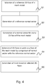
- the mask generation module is capable of generating the mask 250 from a surface 310 (see figure 3B ) of the mesh model 300 by application of the method 400 as depicted in figure 4 .
- the surface 310 is an area of the mesh model 300 corresponding to the planar surface 210 of the 3D-object 200.
- the method 400 starts with a step S1, in which a quad 301' of the area 310 of the mesh model 300 (see figure 3A ). For the sake of clarity, this quad 301' will be referred below as reference quad 301'. In the present example, the selection of the reference quad 301' is done via the user interface.
- the mask generation module of the present example is configured to generate a normal vector 302 corresponding to each of the quads 301 of the mesh model 300.
- the normal vector is arranged outwardly with respect to the 3D-model. Since each of said quads 301 has only two dimensions, there is only a single corresponding normal vector 302 arranged also outwardly for each of said quads 301.
- the following step S2 of the method 400 corresponds to the generation of the normal vector 302' of the reference quad 301' that has been selected in the step S1. This normal vector 302' will be referred as reference normal vector 302'.
- the mask generation module of the present example generates the normal vector corresponding to each of the quads 301 of the plurality according to step S3.
- figure 3A shows the normal vectors 302" and 302"' corresponding to quads 301" and 301"' arranged across the mesh model 300. It is important to note that the mask generation module may also generate normal vectors selectively, that is for squads adjacent to the reference quad, or by choice of the user.
- the mask generation module compares each normal vector 302 with the reference normal vector 302'.
- the quads 301 of the plurality defining an area of the mesh model 300 corresponding to the planar surface 210 of the 3D-object 200 and comprising the reference quad 301' can be detected in an easy way.
- the detection is possible since the normal vectors 302 corresponding to said quads 301 are substantially similar or within a range arranged with respect to the reference normal vector 302' such that all those quads are arranged in a substantially planar area.
- selection of said detected quads 301 by comparison yields the surface 310 having the shape of the planar surface 210.
- the comparison in S4 may be done within a range of values, which is known as tolerance height variation.
- the mask generation unit is configured to set the range as desired, which may have an impact in the selection of the quads 301 depending of the 3D-object.
- the mask 250 is generated. This is achieved since the mask generation module computes the resulting surface 310 to create the rectangular bitmap 251. Then, the resulting surface 310 is used to compute the area 252 and 252' filled with white pixels and the area 253 filled with black pixels. Thus, as both the mask 250 and the area of the mesh model 300 corresponding to the planar surface 210 have the same shape, the mask 250 matches said planar surface 210 of the 3D-object 200.
- Computation of the area 253 may be done by mapping the selected 2D-faces to the mask 250, for example by orthogonal projection. Note that to properly mask out all areas of the image to be printed that will fall outside the substantially planar surface, the size of the mask should at least be the size of the image to be printed, or alternatively the area outside the mask is implicitly to be treated as an area to be masked out, or in other words an area where printing is to be prevented. In a preferred embodiment the dimensions of the mask are determined by the minimum bounding box of the selected 2D-faces or alternatively the axis-aligned minimum bounding box of the selected 2D-faces.
- the image to be printed is mapped to the 3D-model through conventional UV mapping techniques, wherein a mapping maps between the u- and v -coordinates of the image to be printed and the x-, y-, and z-coordinates of the 3D-model.
- the mask 250 may be positioned in the same UV-space as the image to be printed and the UV mapping may be used to map the selected 2D-faces to the mask 250.
- a mapping between the image to be printed and the mask 250 is determined after the mask 250 with the area 253 has been determined, for example by visually relatively positioning and scaling the mask 250 and the image to be printed.
Landscapes
- Engineering & Computer Science (AREA)
- Manufacturing & Machinery (AREA)
- Mechanical Engineering (AREA)
Abstract
Description
- The invention is in the field of printing systems for printing on a substantially planar surface of a 3D-object and a method for printing thereof.
- Printing systems for printing on a substantially planar surface of a 3D-object are known in the art. For example, flatbed printers can be used for applying ink on the planar surface of the 3D-object. Also, flatbed printers can be used for applying several layers of ink in the planar surface to represent texture and to provide tactile details in said planar surface, which is known as 2.5D printing or relief printing.
- The planar surface is a surface of the 3D-object being substantially flat to be printed on. However, the shape of the planar surface may not be rectangular, having rounded parts and angles, and even said planar surface may comprise openings. As consequence, the printing system may provide poor printing since small errors, such as printing on the openings or lateral sides of the 3D-object can be easily seen on the final outcome. Published
U.S. Patent Application 2012/075399 A1 to Polus discloses depositing a substance with a substance-depositing device on the surface of an object by moving the substance-depositing device along the surface, tracking the position of the substance-depositing device, indicating the tracked position on a computer-generated representation of the surface, and commanding the substance-depositing device to deposit the substance on the surface if the indicated tracked position crosses an extruded surface normal to the object surface, the extruded surface determining a location for depositing the substance. - It is an object of the present invention to alleviate the above mentioned problem. To this end, a first aspect of the invention provides a printing system for printing on a substantially planar surface of a 3D-object, the printing system comprising:
- a) printing means for printing on the planar surface of the 3D-object; and
- b) control means configured to control printing of the printing means;
- A second aspect of the invention provides a method for generating a mask of a substantially planar surface of a 3D-object, wherein the mask is generated from a 3D-model of the 3D-object such that said mask has the shape of the planar surface.
- A third aspect of the invention provides a method for printing on a substantially planar surface of a 3D-object, the method comprising the step of using a mask to limit printing to the planar surface of the 3D-object, wherein the method further comprises the step of generating the mask from a 3D-model of the 3D-object such that said mask has the shape of the planar surface to limit printing to said planar surface of the 3D-object. Finally, a fourth aspect of the invention relates to a computer program product comprising a computer readable storage medium, wherein the computer readable storage medium comprises a program, and the program enables a computer and/or a mask generation module of a printing system to execute the method of generating a mask when the program is run in the computer and/or the mask generation module.
- The first aspect of the invention concerns a printing system according to claim 1. In this way, a printing system with improved control for limiting printing to a substantially planar surface of a 3D-object is provided.
- The printing system according to the invention comprises a printing means for printing on the planar surface. The printing system comprises a printer, in general a flatbed printer, comprising a printing head and means for moving the printing head and/or the 3D-object to be printed on to perform printing.
- The printing means is controlled by control means configured to control the printing being performed by said printing means. The control means are arranged for printing and may comprise a user interface comprising a hardware device, a software program, an electronic circuit or combinations thereof for such purpose. In an example of the invention, the printer may comprise the control means. In a more specific example, the control system may be arranged in a workstation detached from the printer, although in communication with said printer to control the printing system.
- The printing system according to the invention further comprises a mask generation module configured to generate a mask and to provide the control means with the mask for printing on said planar surface according to the mask. The use of the mask allows for limiting printing performed by the printing means to a desired area of the 3D-object. The mask may be a bitmap with white pixels corresponding to an area where there is no printing and black pixels corresponding to an area where there is printing, similar to those used in 2.5D printing. The mask generation module may comprise a hardware device, a software program, an electronic circuit or combinations thereof. In a different example, the control means comprises the mask generation module.
- The mask generation module is further configured to generate the mask having an area corresponding to the planar surface of the 3D-object intended to be printed. For such purpose, the mask is obtained from a 3D-model of said 3D-object. In this way, the area defined by the mask for limiting printing corresponds to an area having the shape of the planar surface of the 3D-object. Thus, printing performed by the printing means is improved since rounded parts, angles and openings present in the planar surface of the 3D-object are taken into account.
- The 3D-model may be generated by the printing system, although in general said 3D-model is previously generated by any method known in the art to be input to the printing system for generating the mask. Then, an area of the 3D-model can be selected, in general via the user interface. In a more specific example, the 3D-model may be a mesh model comprising a plurality of 2D-faces, and the faces of the mesh model corresponding to the planar-surface are selected.
- In an embodiment, the mask generation module is configured to generate the shape of the mask from a mesh model defined by a plurality of 2D-faces by selection of 2D-faces of the plurality having a corresponding normal with respect to a reference normal of a
reference 2D-face arranged in a position of the mesh model corresponding to the planar surface of the 3D-object. In this way, the corresponding 2D-faces of an area of the mesh model corresponding to the planar surface of the 3D-model can be easily detected and selected. Further, the accuracy of the shape of the mask with respect to the shape of the planar surface can be increased and thus printing performed in said planar surface is even more accurate. - The use of mesh models as 3D-model of a 3D-object is known in the art. The mesh model may define the 3D-object as a plurality of 2D-faces arranged in space. Each of the 2D-faces of the plurality may have three edges, four edges or even more than four edges to provide a more complex 2D-face, also known as a 2D-polygon. In any case, each of said 2D-faces of the mesh model has two dimensions and, therefore, may define a single normal vector that may be arranged inwardly or outwardly with respect to the 3D-model.
- The mask generation module according to the invention is configured to determine said normal vector of each of the 2D-faces, arranged inwardly or outwardly with respect to the 3D-model and to select 2D-faces of the mesh model according to their normal vectors. In this way, since 2D-faces of the plurality arranged in a position of the mesh model corresponding to the planar surface of the 3D-object has the same or a similar normal vector, said 2D-faces can be easily detected and selected to provide the mask. The second aspect of the invention concerns a method for generating a mask
of a substantially planar surface of a 3D-object, wherein the mask is generated from a 3D-model of the 3D-object such that said mask has the shape of the planar surface. In this way, a mask having the shape of the planar surface of a 3D-object can be easily provided. The mask can be used thus in a printing process to prevent printing outside the planar surface of said 3D-object. - In an embodiment, the 3D-model of the object is a mesh model defined by a plurality of 2D-faces, and the step of generating the mask comprises the sub-steps of:
- a) generating a reference normal vector of a
reference 2D-face arranged in a position of the mesh model corresponding to the planar surface of the 3D-object; - b) generating a normal vector of a 2D-face of the plurality of 2D-faces of said mesh model to yield a normal vector; and
- c) selecting the 2D-face by comparison of its normal vector with the reference normal vector. In this way, a mask having a shape corresponding to the planar surface of the 3D-object can be even more easily generated. Since the mesh model of the 3D-object is defined by the plurality of 2D-faces arranged in space and each 2D-face may define a single normal vector, 2D-faces of the said mesh model corresponding to the planar face of the 3D-object would have a similar or identical single normal vector. Thus, they can be identified and selected to provide the mask.
- The identification and selection is achieved according to a reference normal vector. The reference normal vector is the single normal vector of a 2D-face arranged in an area of the mesh model corresponding to the planar surface. Thus by selection of only one 2D-face corresponding to the planar surface to be printed, the reference normal vector arranged inwardly or outwardly with respect to the 3D-model can be obtained for comparison.
- The comparison may be done once at least a normal vector corresponding to a 2D-face is generated. In an example, normal vectors are generated for 2D-faces adjacent to the
reference 2D-face. Then, if said adjacent 2D-faces are selected after comparison, further normal vectors corresponding to further 2D-faces adjacent to said adjacent 2D-faces are generated. These sub-steps will continue until comparison does not allow for selection of more 2D-faces. In a more specific example, all the normal vector for all the 2D-faces are generated for comparison. - If the reference normal vector is generated inwardly with respect to the 3D-model, the normal vectors for comparison are also to be generated inwardly. The same is to be acknowledged if the reference normal vector is arranged outwardly, the normal vectors for comparison being also arranged outwardly.
- The comparison sub-step is achieved by comparing the reference normal vector with the normal vector of a 2D-face within a range. The range is defined such that the 2D-face defined by said normal vector in combination with the
reference 2D-plane defines a substantially planar surface of the 3D-object. Thus, the range selected further allows for controlling the accuracy of the shape of the mask during the selection of the 2D-faces depending on the range of variation. Thus, the smaller the range of variation, the more accurate the selection is, and the more similar the shape of the mask is with respect to the shape of the planar surface. In an example of the invention, the selecting sub-step may be done only when both the normal vector and the reference normal vector are substantially equal, providing the highest accuracy. - The
reference 2D-face may be selected by a user selecting such 2D-face displayed in a user interface displaying the 3D-model or part of the 3D-model. The selecting in the user interface may be done by means of a pointing device as is known in the art. - The third aspect of the invention concerns a method for printing on a planar surface of a 3D-object, the method comprising the step of using a mask to limit printing to the planar surface, wherein the mask is generated from a 3D-model of the object as mentioned above. In this way, a method providing a more accurate printing on a planar surface of a 3D-object is achieved. In the method, a printing system may be arranged for generating the 3D-model by any method known in the art via the mask generation module. In a different example, a printing system known in the art, such as a flatbed printer is further configured to provide printing by using a mask, the mask being obtained from a 3D-model by any method known in the art. In both examples the mask used has a shape according the area of the 3D-model corresponding to said planar surface of the 3D-object. The method may be performed by the printing system according to the invention as defined above.
- The fourth aspect of the invention concerns a computer program product comprising a computer readable storage medium, wherein the computer readable storage medium comprises a program, and the program enables a computer and/or a mask generation module of a printing system to execute the method of generating a mask according to anyone of claims 3 to 5 when the program is run in the computer and/or the mask generation module.
- For the purpose of illustrating the invention, the drawings show aspects of one or more embodiments of said invention. However, it should be understood that the present invention is not limited to the precise arrangements and instrumentalities shown in the drawings, wherein:
-
Fig. 1 is a view of a printer according to the invention; -
Fig. 2A is a view of a 3D-object to be printed on; -
Fig. 2B is a view of a mask to be used for printing a surface of the 3D-object depicted infigure 2A ; -
Fig. 3A is a view of a 3D-model of the 3D-object offigure 2A ; -
Fig. 3B is a surface of the 3D-model offigure 3A ; and -
Fig. 4 is a schematic view of a printing method using the printer offigure 1 - It should be noted that items which have the same reference numbers in different figures, have the same structural features and the same functions. Where the function and/or structure of such item has been explained, there is no necessity for repeated explanation thereof in the detailed description.
- It should be noted that the above-mentioned embodiments illustrate rather than limit the invention, and that those skilled in the art will be able to design many alternative embodiments.
-
Figure 1 depicts aprinting system 100 according to an example of the invention. Theprinting system 100 comprises aflatbed printer 101 as known in the art. Theflatbed printer 101 comprises a carriage comprising printing means 110. Control means are arranged in a detached workstation (not shown). The printing means 110 comprises aprint head 111 arranged on agantry 112. In this way the printing head may move in a X, Y and Z direction thanks to the cooperation with thegantry 112. The control means comprises a user interface for controlling printing performed by theflatbed printer 101. Theflatbed printer 101 is configured to print on 3D-objects, as for example a 3D-object 200 depicted infigure 2 , in the present example by having a gantry adjustable in height. - The printing means 110 may thus apply ink to a
planar surface 210 of the 3D-object 200 via theprinting head 111 according to the instructions provided by the control means. A challenge that the printing means 110 faces when printing on theplanar surface 210 of the 3D-object 200 depicted infigure 2A is that the perimeter of saidplanar surface 210 is rounded and further comprises anopening 220. This might make it difficult to control printing and increases the possibility of applying ink in theopening 220 or thelateral surfaces 230 and 230' of the 3D-object 200, which can be easily noticed in the printing outcome. - In order to improve control of the printing means 110, the
printing system 100 further comprises a mask generation module. In the present example, the mask generation module is a software program arranged in the user interface and configured to provide a mask 250 (seefigure 2B ) from a 3D-model 300 (seefigure 3 ) of the 3D-object 200. Further, the mask generation module is further configured to provide the control means with the mask to limit printing provided by the printing means 110 to saidplanar surface 210 according to themask 250. However, it is important to note that in a more specific example, a flatbed printer may be configured to perform printing according to a mask and that said mask is obtained offline, that is that said mask is generated separately from the flatbed printer to be input to the control means together with an image to be printed on the substantially planar surface to perform printing. - The
mask 250 comprises arectangular bitmap 251 having anarea 252 and 252' filled with white pixels and anarea 253 filled with black pixels. Theareas 252 and 252' represent the area of the mask where there will be no printing and thearea 253 represent the area where there is printing, as known in 2.5D printing. It is important to note that other descriptions of the mask known in the art may be used. - The
mask 250 generated by the mask generation module is obtained from a 3D-model 300 of the 3D-object 200, as depicted infigure 3A . In the present example, the 3D-model 300 ismesh model 300. Themesh model 300 may have been obtained by any method known in the art for such a purpose to be input to the mask generation module of theprinting system 100. - The
mesh model 300 defines the 3D-object 200 as a plurality of 2D-faces 301 arranged in space. In the present example, each 2D-face 301 of the plurality has four edges, corresponding to aquad 301. - In the present example, the mask generation module is capable of generating the
mask 250 from a surface 310 (seefigure 3B ) of themesh model 300 by application of the method 400 as depicted infigure 4 . Thesurface 310 is an area of themesh model 300 corresponding to theplanar surface 210 of the 3D-object 200. - The method 400 starts with a step S1, in which a quad 301' of the
area 310 of the mesh model 300 (seefigure 3A ). For the sake of clarity, this quad 301' will be referred below as reference quad 301'. In the present example, the selection of the reference quad 301' is done via the user interface. - The mask generation module of the present example is configured to generate a
normal vector 302 corresponding to each of thequads 301 of themesh model 300. In the present example, the normal vector is arranged outwardly with respect to the 3D-model. Since each of saidquads 301 has only two dimensions, there is only a single correspondingnormal vector 302 arranged also outwardly for each of saidquads 301. Thus, the following step S2 of the method 400 corresponds to the generation of the normal vector 302' of the reference quad 301' that has been selected in the step S1. This normal vector 302' will be referred as reference normal vector 302'. - Then, the mask generation module of the present example generates the normal vector corresponding to each of the
quads 301 of the plurality according to step S3. For the sake of clarity,figure 3A shows thenormal vectors 302" and 302"' corresponding toquads 301" and 301"' arranged across themesh model 300. It is important to note that the mask generation module may also generate normal vectors selectively, that is for squads adjacent to the reference quad, or by choice of the user. - In a following step S4, the mask generation module compares each
normal vector 302 with the reference normal vector 302'. In this way, thequads 301 of the plurality defining an area of themesh model 300 corresponding to theplanar surface 210 of the 3D-object 200 and comprising the reference quad 301' can be detected in an easy way. The detection is possible since thenormal vectors 302 corresponding to saidquads 301 are substantially similar or within a range arranged with respect to the reference normal vector 302' such that all those quads are arranged in a substantially planar area. Thus, selection of said detectedquads 301 by comparison yields thesurface 310 having the shape of theplanar surface 210. - It has to be noted, that the comparison in S4 may be done within a range of values, which is known as tolerance height variation. In the present example, the mask generation unit is configured to set the range as desired, which may have an impact in the selection of the
quads 301 depending of the 3D-object. - In a final step S5, the
mask 250 is generated. This is achieved since the mask generation module computes the resultingsurface 310 to create therectangular bitmap 251. Then, the resultingsurface 310 is used to compute thearea 252 and 252' filled with white pixels and thearea 253 filled with black pixels. Thus, as both themask 250 and the area of themesh model 300 corresponding to theplanar surface 210 have the same shape, themask 250 matches saidplanar surface 210 of the 3D-object 200. - Computation of the
area 253 may be done by mapping the selected 2D-faces to themask 250, for example by orthogonal projection. Note that to properly mask out all areas of the image to be printed that will fall outside the substantially planar surface, the size of the mask should at least be the size of the image to be printed, or alternatively the area outside the mask is implicitly to be treated as an area to be masked out, or in other words an area where printing is to be prevented. In a preferred embodiment the dimensions of the mask are determined by the minimum bounding box of the selected 2D-faces or alternatively the axis-aligned minimum bounding box of the selected 2D-faces. - In one particular embodiment, the image to be printed is mapped to the 3D-model through conventional UV mapping techniques, wherein a mapping maps between the u- and v-coordinates of the image to be printed and the x-, y-, and z-coordinates of the 3D-model. In such embodiment, the
mask 250 may be positioned in the same UV-space as the image to be printed and the UV mapping may be used to map the selected 2D-faces to themask 250. Alternatively, a mapping between the image to be printed and themask 250 is determined after themask 250 with thearea 253 has been determined, for example by visually relatively positioning and scaling themask 250 and the image to be printed.
Claims (7)
- A printing system (100) for printing on a substantially planar surface (210) of a 3D-object (200), the printing system (100) comprising:a) printing means (110) for printing on the planar surface (210) of the 3D-object (200); andb) control means configured to control printing of the printing means (110); characterised in thatthe printing system (100) further comprises a mask generation module configured to generate a mask (250) having the shape of the planar surface (210) from a 3D-model (300) of the 3D-object (200) and to provide the control means with the mask to prevent printing outside said planar surface (210) according to the mask (250).
- The printing system (100) according to claim 1, wherein the mask generation module is configured to generate the shape of the mask (250) from a mesh model (300) defined by a plurality of 2D-faces (301) by selection of 2D-faces (301) of the plurality having a corresponding normal (302) with respect to a reference normal (302') of a reference 2D-face (301') arranged in an area of the mesh model (300) corresponding to the planar surface (210) of the 3D-object (200).
- A method for generating a mask (250) of a substantially planar surface (210) of a 3D-object (200), characterised in that the mask (250) is generated from a 3D-model (300) of the 3D-object (200) such that said mask (250) has the shape of the planar surface (210).
- The method according to claim 3, wherein the 3D-model (300) of the 3D-object object (200) is a mesh model (300) defined by a plurality of 2D-faces (301), and the step of generating the mask (250) comprises the sub-steps of:a) generating a reference normal (302) vector of a reference 2D-face arranged in an area of the mesh model (300) corresponding to the planar surface (210) of the 3D-object (200);b) generating a normal (302) vector of a 2D-face (301) of the plurality of 2D-faces (301) of said mesh model (300) to yield a normal (302) vector; andc) selecting the 2D-face (301) by comparison of the normal (302) vector with the reference normal (302) vector.
- The method according to claim 4, wherein the selecting sub-step is done when both the normal (302) vector and the reference normal (302) vector are substantially equal.
- A method for printing on a planar surface (210) of a 3D-object (200), the method comprising the step of using a mask (250) to limit printing, wherein the mask (250) is generated according to a method corresponding to anyone of claims 3 to 5.
- A computer program product comprising a computer readable storage medium, wherein the computer readable storage medium comprises a program, and the program enables a computer and/or a mask generation module of a printing system (100) to execute the method of generating a mask (250) according to anyone of claims 3 to 5 when the program is run in the computer and/or the mask generation module.
Applications Claiming Priority (1)
| Application Number | Priority Date | Filing Date | Title |
|---|---|---|---|
| EP16173907 | 2016-06-10 |
Publications (2)
| Publication Number | Publication Date |
|---|---|
| EP3254857A1 true EP3254857A1 (en) | 2017-12-13 |
| EP3254857B1 EP3254857B1 (en) | 2020-07-29 |
Family
ID=56117622
Family Applications (1)
| Application Number | Title | Priority Date | Filing Date |
|---|---|---|---|
| EP17173377.7A Active EP3254857B1 (en) | 2016-06-10 | 2017-05-30 | A printing system for printing on a substantially planar surface of a 3d-object and a method for printing thereon |
Country Status (2)
| Country | Link |
|---|---|
| US (1) | US10239307B2 (en) |
| EP (1) | EP3254857B1 (en) |
Families Citing this family (1)
| Publication number | Priority date | Publication date | Assignee | Title |
|---|---|---|---|---|
| US11270049B2 (en) * | 2018-09-12 | 2022-03-08 | Siemens Industry Software Inc. | Internal channel network detections for 3D printing |
Citations (2)
| Publication number | Priority date | Publication date | Assignee | Title |
|---|---|---|---|---|
| US20120075399A1 (en) | 2005-04-22 | 2012-03-29 | The Boeing Company | Printing methods and systems |
| US20140026773A1 (en) * | 2012-07-25 | 2014-01-30 | Nike, Inc. | Projector Assisted Alignment and Printing |
Family Cites Families (4)
| Publication number | Priority date | Publication date | Assignee | Title |
|---|---|---|---|---|
| US8243334B2 (en) * | 2008-06-06 | 2012-08-14 | Virginia Venture Industries, Llc | Methods and apparatuses for printing three dimensional images |
| US9269022B2 (en) * | 2013-04-11 | 2016-02-23 | Digimarc Corporation | Methods for object recognition and related arrangements |
| US10204447B2 (en) * | 2015-11-06 | 2019-02-12 | Microsoft Technology Licensing, Llc | 2D image processing for extrusion into 3D objects |
| KR102433392B1 (en) * | 2016-03-04 | 2022-08-17 | 한국전자통신연구원 | 3D volume mask model information generating apparatus and method therefor |
-
2017
- 2017-05-30 EP EP17173377.7A patent/EP3254857B1/en active Active
- 2017-06-09 US US15/619,057 patent/US10239307B2/en active Active
Patent Citations (2)
| Publication number | Priority date | Publication date | Assignee | Title |
|---|---|---|---|---|
| US20120075399A1 (en) | 2005-04-22 | 2012-03-29 | The Boeing Company | Printing methods and systems |
| US20140026773A1 (en) * | 2012-07-25 | 2014-01-30 | Nike, Inc. | Projector Assisted Alignment and Printing |
Also Published As
| Publication number | Publication date |
|---|---|
| EP3254857B1 (en) | 2020-07-29 |
| US10239307B2 (en) | 2019-03-26 |
| US20170355184A1 (en) | 2017-12-14 |
Similar Documents
| Publication | Publication Date | Title |
|---|---|---|
| US10994490B1 (en) | Calibration for additive manufacturing by compensating for geometric misalignments and distortions between components of a 3D printer | |
| EP4329296B1 (en) | System and methods for extrinsic calibration of cameras and diffractive optical elements | |
| US10872439B2 (en) | Method and device for verification | |
| EP3622481B1 (en) | Method and system for calibrating a velocimetry system | |
| AU2025205096A1 (en) | Systems and methods for generating augmented reality environments from two-dimensional drawings | |
| US8982127B2 (en) | Computing device and method for establishing three dimensional coordinate system using graphics | |
| US10412359B2 (en) | Method for generating a virtual image of vehicle surroundings | |
| CN108713216B (en) | Method for perspective transformation and output of image content, head-up display and output system, and vehicle | |
| US9950516B1 (en) | Method of slicing and printing multi-colour 3D object | |
| US20210349440A1 (en) | Geometrical Compensations for Additive Manufacturing | |
| EP3627255A1 (en) | Method for detecting object border of 3d printer | |
| CN112560126B (en) | Data processing method, system and storage medium for 3D printing | |
| CN108074237A (en) | Approach for detecting image sharpness, device, storage medium and electronic equipment | |
| CN113269728B (en) | Visual edge-tracking method, device, readable storage medium and program product | |
| EP3254857B1 (en) | A printing system for printing on a substantially planar surface of a 3d-object and a method for printing thereon | |
| CN112381876B (en) | Traffic sign marking method and device and computer equipment | |
| JP2021017047A (en) | Horizontal plane slicing method for color 3d objects | |
| CN114387347A (en) | Method and device for determining external parameter calibration, electronic equipment and medium | |
| US11941852B2 (en) | Three-dimensional measurement device, three-dimensional measurement method, and three-dimensional measurement program | |
| US20250278859A1 (en) | Image point cloud data processing device, image point cloud data processing method, and storage medium storing image point cloud data processing program | |
| CN118875535B (en) | Cutting method, apparatus, computer device, readable storage medium, and program product | |
| US20210124969A1 (en) | Planar and/or undistorted texture image corresponding to captured image of object | |
| CN112785909B (en) | Determination method and device for occupying grid map | |
| EP4435722A1 (en) | Method for verifying calibrated extrinsic parameter values of camera, device and medium | |
| CN108874328B (en) | Method and device for generating test file of printer nozzle |
Legal Events
| Date | Code | Title | Description |
|---|---|---|---|
| PUAI | Public reference made under article 153(3) epc to a published international application that has entered the european phase |
Free format text: ORIGINAL CODE: 0009012 |
|
| STAA | Information on the status of an ep patent application or granted ep patent |
Free format text: STATUS: THE APPLICATION HAS BEEN PUBLISHED |
|
| AK | Designated contracting states |
Kind code of ref document: A1 Designated state(s): AL AT BE BG CH CY CZ DE DK EE ES FI FR GB GR HR HU IE IS IT LI LT LU LV MC MK MT NL NO PL PT RO RS SE SI SK SM TR |
|
| AX | Request for extension of the european patent |
Extension state: BA ME |
|
| STAA | Information on the status of an ep patent application or granted ep patent |
Free format text: STATUS: REQUEST FOR EXAMINATION WAS MADE |
|
| 17P | Request for examination filed |
Effective date: 20180613 |
|
| RBV | Designated contracting states (corrected) |
Designated state(s): AL AT BE BG CH CY CZ DE DK EE ES FI FR GB GR HR HU IE IS IT LI LT LU LV MC MK MT NL NO PL PT RO RS SE SI SK SM TR |
|
| GRAP | Despatch of communication of intention to grant a patent |
Free format text: ORIGINAL CODE: EPIDOSNIGR1 |
|
| STAA | Information on the status of an ep patent application or granted ep patent |
Free format text: STATUS: GRANT OF PATENT IS INTENDED |
|
| RIC1 | Information provided on ipc code assigned before grant |
Ipc: B41J 3/407 20060101AFI20200213BHEP |
|
| RAP1 | Party data changed (applicant data changed or rights of an application transferred) |
Owner name: CANON PRODUCTION PRINTING HOLDING B.V. |
|
| INTG | Intention to grant announced |
Effective date: 20200303 |
|
| GRAS | Grant fee paid |
Free format text: ORIGINAL CODE: EPIDOSNIGR3 |
|
| GRAA | (expected) grant |
Free format text: ORIGINAL CODE: 0009210 |
|
| STAA | Information on the status of an ep patent application or granted ep patent |
Free format text: STATUS: THE PATENT HAS BEEN GRANTED |
|
| AK | Designated contracting states |
Kind code of ref document: B1 Designated state(s): AL AT BE BG CH CY CZ DE DK EE ES FI FR GB GR HR HU IE IS IT LI LT LU LV MC MK MT NL NO PL PT RO RS SE SI SK SM TR |
|
| REG | Reference to a national code |
Ref country code: CH Ref legal event code: EP |
|
| REG | Reference to a national code |
Ref country code: AT Ref legal event code: REF Ref document number: 1295340 Country of ref document: AT Kind code of ref document: T Effective date: 20200815 |
|
| REG | Reference to a national code |
Ref country code: IE Ref legal event code: FG4D |
|
| REG | Reference to a national code |
Ref country code: DE Ref legal event code: R096 Ref document number: 602017020421 Country of ref document: DE |
|
| REG | Reference to a national code |
Ref country code: NL Ref legal event code: FP |
|
| RAP2 | Party data changed (patent owner data changed or rights of a patent transferred) |
Owner name: CANON PRODUCTION PRINTING HOLDING B.V. |
|
| REG | Reference to a national code |
Ref country code: LT Ref legal event code: MG4D |
|
| REG | Reference to a national code |
Ref country code: AT Ref legal event code: MK05 Ref document number: 1295340 Country of ref document: AT Kind code of ref document: T Effective date: 20200729 |
|
| PG25 | Lapsed in a contracting state [announced via postgrant information from national office to epo] |
Ref country code: AT Free format text: LAPSE BECAUSE OF FAILURE TO SUBMIT A TRANSLATION OF THE DESCRIPTION OR TO PAY THE FEE WITHIN THE PRESCRIBED TIME-LIMIT Effective date: 20200729 Ref country code: HR Free format text: LAPSE BECAUSE OF FAILURE TO SUBMIT A TRANSLATION OF THE DESCRIPTION OR TO PAY THE FEE WITHIN THE PRESCRIBED TIME-LIMIT Effective date: 20200729 Ref country code: LT Free format text: LAPSE BECAUSE OF FAILURE TO SUBMIT A TRANSLATION OF THE DESCRIPTION OR TO PAY THE FEE WITHIN THE PRESCRIBED TIME-LIMIT Effective date: 20200729 Ref country code: NO Free format text: LAPSE BECAUSE OF FAILURE TO SUBMIT A TRANSLATION OF THE DESCRIPTION OR TO PAY THE FEE WITHIN THE PRESCRIBED TIME-LIMIT Effective date: 20201029 Ref country code: FI Free format text: LAPSE BECAUSE OF FAILURE TO SUBMIT A TRANSLATION OF THE DESCRIPTION OR TO PAY THE FEE WITHIN THE PRESCRIBED TIME-LIMIT Effective date: 20200729 Ref country code: SE Free format text: LAPSE BECAUSE OF FAILURE TO SUBMIT A TRANSLATION OF THE DESCRIPTION OR TO PAY THE FEE WITHIN THE PRESCRIBED TIME-LIMIT Effective date: 20200729 Ref country code: PT Free format text: LAPSE BECAUSE OF FAILURE TO SUBMIT A TRANSLATION OF THE DESCRIPTION OR TO PAY THE FEE WITHIN THE PRESCRIBED TIME-LIMIT Effective date: 20201130 Ref country code: ES Free format text: LAPSE BECAUSE OF FAILURE TO SUBMIT A TRANSLATION OF THE DESCRIPTION OR TO PAY THE FEE WITHIN THE PRESCRIBED TIME-LIMIT Effective date: 20200729 Ref country code: GR Free format text: LAPSE BECAUSE OF FAILURE TO SUBMIT A TRANSLATION OF THE DESCRIPTION OR TO PAY THE FEE WITHIN THE PRESCRIBED TIME-LIMIT Effective date: 20201030 Ref country code: BG Free format text: LAPSE BECAUSE OF FAILURE TO SUBMIT A TRANSLATION OF THE DESCRIPTION OR TO PAY THE FEE WITHIN THE PRESCRIBED TIME-LIMIT Effective date: 20201029 |
|
| PG25 | Lapsed in a contracting state [announced via postgrant information from national office to epo] |
Ref country code: LV Free format text: LAPSE BECAUSE OF FAILURE TO SUBMIT A TRANSLATION OF THE DESCRIPTION OR TO PAY THE FEE WITHIN THE PRESCRIBED TIME-LIMIT Effective date: 20200729 Ref country code: RS Free format text: LAPSE BECAUSE OF FAILURE TO SUBMIT A TRANSLATION OF THE DESCRIPTION OR TO PAY THE FEE WITHIN THE PRESCRIBED TIME-LIMIT Effective date: 20200729 Ref country code: PL Free format text: LAPSE BECAUSE OF FAILURE TO SUBMIT A TRANSLATION OF THE DESCRIPTION OR TO PAY THE FEE WITHIN THE PRESCRIBED TIME-LIMIT Effective date: 20200729 Ref country code: IS Free format text: LAPSE BECAUSE OF FAILURE TO SUBMIT A TRANSLATION OF THE DESCRIPTION OR TO PAY THE FEE WITHIN THE PRESCRIBED TIME-LIMIT Effective date: 20201129 |
|
| PG25 | Lapsed in a contracting state [announced via postgrant information from national office to epo] |
Ref country code: EE Free format text: LAPSE BECAUSE OF FAILURE TO SUBMIT A TRANSLATION OF THE DESCRIPTION OR TO PAY THE FEE WITHIN THE PRESCRIBED TIME-LIMIT Effective date: 20200729 Ref country code: IT Free format text: LAPSE BECAUSE OF FAILURE TO SUBMIT A TRANSLATION OF THE DESCRIPTION OR TO PAY THE FEE WITHIN THE PRESCRIBED TIME-LIMIT Effective date: 20200729 Ref country code: SM Free format text: LAPSE BECAUSE OF FAILURE TO SUBMIT A TRANSLATION OF THE DESCRIPTION OR TO PAY THE FEE WITHIN THE PRESCRIBED TIME-LIMIT Effective date: 20200729 Ref country code: CZ Free format text: LAPSE BECAUSE OF FAILURE TO SUBMIT A TRANSLATION OF THE DESCRIPTION OR TO PAY THE FEE WITHIN THE PRESCRIBED TIME-LIMIT Effective date: 20200729 Ref country code: DK Free format text: LAPSE BECAUSE OF FAILURE TO SUBMIT A TRANSLATION OF THE DESCRIPTION OR TO PAY THE FEE WITHIN THE PRESCRIBED TIME-LIMIT Effective date: 20200729 Ref country code: RO Free format text: LAPSE BECAUSE OF FAILURE TO SUBMIT A TRANSLATION OF THE DESCRIPTION OR TO PAY THE FEE WITHIN THE PRESCRIBED TIME-LIMIT Effective date: 20200729 |
|
| REG | Reference to a national code |
Ref country code: DE Ref legal event code: R097 Ref document number: 602017020421 Country of ref document: DE |
|
| PG25 | Lapsed in a contracting state [announced via postgrant information from national office to epo] |
Ref country code: AL Free format text: LAPSE BECAUSE OF FAILURE TO SUBMIT A TRANSLATION OF THE DESCRIPTION OR TO PAY THE FEE WITHIN THE PRESCRIBED TIME-LIMIT Effective date: 20200729 |
|
| PLBE | No opposition filed within time limit |
Free format text: ORIGINAL CODE: 0009261 |
|
| STAA | Information on the status of an ep patent application or granted ep patent |
Free format text: STATUS: NO OPPOSITION FILED WITHIN TIME LIMIT |
|
| PG25 | Lapsed in a contracting state [announced via postgrant information from national office to epo] |
Ref country code: SK Free format text: LAPSE BECAUSE OF FAILURE TO SUBMIT A TRANSLATION OF THE DESCRIPTION OR TO PAY THE FEE WITHIN THE PRESCRIBED TIME-LIMIT Effective date: 20200729 |
|
| 26N | No opposition filed |
Effective date: 20210430 |
|
| PG25 | Lapsed in a contracting state [announced via postgrant information from national office to epo] |
Ref country code: SI Free format text: LAPSE BECAUSE OF FAILURE TO SUBMIT A TRANSLATION OF THE DESCRIPTION OR TO PAY THE FEE WITHIN THE PRESCRIBED TIME-LIMIT Effective date: 20200729 |
|
| REG | Reference to a national code |
Ref country code: CH Ref legal event code: PL |
|
| PG25 | Lapsed in a contracting state [announced via postgrant information from national office to epo] |
Ref country code: LU Free format text: LAPSE BECAUSE OF NON-PAYMENT OF DUE FEES Effective date: 20210530 Ref country code: LI Free format text: LAPSE BECAUSE OF NON-PAYMENT OF DUE FEES Effective date: 20210531 Ref country code: MC Free format text: LAPSE BECAUSE OF FAILURE TO SUBMIT A TRANSLATION OF THE DESCRIPTION OR TO PAY THE FEE WITHIN THE PRESCRIBED TIME-LIMIT Effective date: 20200729 Ref country code: CH Free format text: LAPSE BECAUSE OF NON-PAYMENT OF DUE FEES Effective date: 20210531 |
|
| REG | Reference to a national code |
Ref country code: BE Ref legal event code: MM Effective date: 20210531 |
|
| PG25 | Lapsed in a contracting state [announced via postgrant information from national office to epo] |
Ref country code: IE Free format text: LAPSE BECAUSE OF NON-PAYMENT OF DUE FEES Effective date: 20210530 |
|
| PG25 | Lapsed in a contracting state [announced via postgrant information from national office to epo] |
Ref country code: BE Free format text: LAPSE BECAUSE OF NON-PAYMENT OF DUE FEES Effective date: 20210531 |
|
| PG25 | Lapsed in a contracting state [announced via postgrant information from national office to epo] |
Ref country code: HU Free format text: LAPSE BECAUSE OF FAILURE TO SUBMIT A TRANSLATION OF THE DESCRIPTION OR TO PAY THE FEE WITHIN THE PRESCRIBED TIME-LIMIT; INVALID AB INITIO Effective date: 20170530 |
|
| PG25 | Lapsed in a contracting state [announced via postgrant information from national office to epo] |
Ref country code: CY Free format text: LAPSE BECAUSE OF FAILURE TO SUBMIT A TRANSLATION OF THE DESCRIPTION OR TO PAY THE FEE WITHIN THE PRESCRIBED TIME-LIMIT Effective date: 20200729 |
|
| PG25 | Lapsed in a contracting state [announced via postgrant information from national office to epo] |
Ref country code: MK Free format text: LAPSE BECAUSE OF FAILURE TO SUBMIT A TRANSLATION OF THE DESCRIPTION OR TO PAY THE FEE WITHIN THE PRESCRIBED TIME-LIMIT Effective date: 20200729 |
|
| PG25 | Lapsed in a contracting state [announced via postgrant information from national office to epo] |
Ref country code: MT Free format text: LAPSE BECAUSE OF FAILURE TO SUBMIT A TRANSLATION OF THE DESCRIPTION OR TO PAY THE FEE WITHIN THE PRESCRIBED TIME-LIMIT Effective date: 20200729 |
|
| PGFP | Annual fee paid to national office [announced via postgrant information from national office to epo] |
Ref country code: NL Payment date: 20250417 Year of fee payment: 9 |
|
| PGFP | Annual fee paid to national office [announced via postgrant information from national office to epo] |
Ref country code: DE Payment date: 20250521 Year of fee payment: 9 |
|
| PGFP | Annual fee paid to national office [announced via postgrant information from national office to epo] |
Ref country code: GB Payment date: 20250527 Year of fee payment: 9 |
|
| PGFP | Annual fee paid to national office [announced via postgrant information from national office to epo] |
Ref country code: FR Payment date: 20250528 Year of fee payment: 9 |
|
| PG25 | Lapsed in a contracting state [announced via postgrant information from national office to epo] |
Ref country code: TR Free format text: LAPSE BECAUSE OF FAILURE TO SUBMIT A TRANSLATION OF THE DESCRIPTION OR TO PAY THE FEE WITHIN THE PRESCRIBED TIME-LIMIT Effective date: 20200729 |