EP3254819A1 - Tire molding die and pneumatic tire - Google Patents
Tire molding die and pneumatic tire Download PDFInfo
- Publication number
- EP3254819A1 EP3254819A1 EP16746699.4A EP16746699A EP3254819A1 EP 3254819 A1 EP3254819 A1 EP 3254819A1 EP 16746699 A EP16746699 A EP 16746699A EP 3254819 A1 EP3254819 A1 EP 3254819A1
- Authority
- EP
- European Patent Office
- Prior art keywords
- mold
- tire
- region
- pin
- insertion hole
- Prior art date
- Legal status (The legal status is an assumption and is not a legal conclusion. Google has not performed a legal analysis and makes no representation as to the accuracy of the status listed.)
- Withdrawn
Links
Images





Classifications
-
- B—PERFORMING OPERATIONS; TRANSPORTING
- B29—WORKING OF PLASTICS; WORKING OF SUBSTANCES IN A PLASTIC STATE IN GENERAL
- B29D—PRODUCING PARTICULAR ARTICLES FROM PLASTICS OR FROM SUBSTANCES IN A PLASTIC STATE
- B29D30/00—Producing pneumatic or solid tyres or parts thereof
- B29D30/06—Pneumatic tyres or parts thereof (e.g. produced by casting, moulding, compression moulding, injection moulding, centrifugal casting)
- B29D30/0601—Vulcanising tyres; Vulcanising presses for tyres
- B29D30/0606—Vulcanising moulds not integral with vulcanising presses
-
- B—PERFORMING OPERATIONS; TRANSPORTING
- B29—WORKING OF PLASTICS; WORKING OF SUBSTANCES IN A PLASTIC STATE IN GENERAL
- B29C—SHAPING OR JOINING OF PLASTICS; SHAPING OF MATERIAL IN A PLASTIC STATE, NOT OTHERWISE PROVIDED FOR; AFTER-TREATMENT OF THE SHAPED PRODUCTS, e.g. REPAIRING
- B29C33/00—Moulds or cores; Details thereof or accessories therefor
- B29C33/02—Moulds or cores; Details thereof or accessories therefor with incorporated heating or cooling means
-
- B—PERFORMING OPERATIONS; TRANSPORTING
- B29—WORKING OF PLASTICS; WORKING OF SUBSTANCES IN A PLASTIC STATE IN GENERAL
- B29C—SHAPING OR JOINING OF PLASTICS; SHAPING OF MATERIAL IN A PLASTIC STATE, NOT OTHERWISE PROVIDED FOR; AFTER-TREATMENT OF THE SHAPED PRODUCTS, e.g. REPAIRING
- B29C35/00—Heating, cooling or curing, e.g. crosslinking or vulcanising; Apparatus therefor
- B29C35/02—Heating or curing, e.g. crosslinking or vulcanizing during moulding, e.g. in a mould
-
- B—PERFORMING OPERATIONS; TRANSPORTING
- B60—VEHICLES IN GENERAL
- B60C—VEHICLE TYRES; TYRE INFLATION; TYRE CHANGING; CONNECTING VALVES TO INFLATABLE ELASTIC BODIES IN GENERAL; DEVICES OR ARRANGEMENTS RELATED TO TYRES
- B60C11/00—Tyre tread bands; Tread patterns; Anti-skid inserts
- B60C11/14—Anti-skid inserts, e.g. vulcanised into the tread band
- B60C11/16—Anti-skid inserts, e.g. vulcanised into the tread band of plug form, e.g. made from metal, textile
-
- B—PERFORMING OPERATIONS; TRANSPORTING
- B60—VEHICLES IN GENERAL
- B60C—VEHICLE TYRES; TYRE INFLATION; TYRE CHANGING; CONNECTING VALVES TO INFLATABLE ELASTIC BODIES IN GENERAL; DEVICES OR ARRANGEMENTS RELATED TO TYRES
- B60C11/00—Tyre tread bands; Tread patterns; Anti-skid inserts
- B60C11/14—Anti-skid inserts, e.g. vulcanised into the tread band
- B60C11/16—Anti-skid inserts, e.g. vulcanised into the tread band of plug form, e.g. made from metal, textile
- B60C11/1625—Arrangements thereof in the tread patterns, e.g. irregular
-
- B—PERFORMING OPERATIONS; TRANSPORTING
- B60—VEHICLES IN GENERAL
- B60C—VEHICLE TYRES; TYRE INFLATION; TYRE CHANGING; CONNECTING VALVES TO INFLATABLE ELASTIC BODIES IN GENERAL; DEVICES OR ARRANGEMENTS RELATED TO TYRES
- B60C11/00—Tyre tread bands; Tread patterns; Anti-skid inserts
- B60C11/14—Anti-skid inserts, e.g. vulcanised into the tread band
- B60C11/16—Anti-skid inserts, e.g. vulcanised into the tread band of plug form, e.g. made from metal, textile
- B60C11/1643—Anti-skid inserts, e.g. vulcanised into the tread band of plug form, e.g. made from metal, textile with special shape of the plug-body portion, i.e. not cylindrical
- B60C11/1656—Anti-skid inserts, e.g. vulcanised into the tread band of plug form, e.g. made from metal, textile with special shape of the plug-body portion, i.e. not cylindrical concave or convex, e.g. barrel-shaped
-
- B—PERFORMING OPERATIONS; TRANSPORTING
- B60—VEHICLES IN GENERAL
- B60C—VEHICLE TYRES; TYRE INFLATION; TYRE CHANGING; CONNECTING VALVES TO INFLATABLE ELASTIC BODIES IN GENERAL; DEVICES OR ARRANGEMENTS RELATED TO TYRES
- B60C11/00—Tyre tread bands; Tread patterns; Anti-skid inserts
- B60C11/14—Anti-skid inserts, e.g. vulcanised into the tread band
- B60C11/16—Anti-skid inserts, e.g. vulcanised into the tread band of plug form, e.g. made from metal, textile
- B60C11/1643—Anti-skid inserts, e.g. vulcanised into the tread band of plug form, e.g. made from metal, textile with special shape of the plug-body portion, i.e. not cylindrical
- B60C11/1668—Anti-skid inserts, e.g. vulcanised into the tread band of plug form, e.g. made from metal, textile with special shape of the plug-body portion, i.e. not cylindrical with an additional collar
-
- B—PERFORMING OPERATIONS; TRANSPORTING
- B29—WORKING OF PLASTICS; WORKING OF SUBSTANCES IN A PLASTIC STATE IN GENERAL
- B29D—PRODUCING PARTICULAR ARTICLES FROM PLASTICS OR FROM SUBSTANCES IN A PLASTIC STATE
- B29D30/00—Producing pneumatic or solid tyres or parts thereof
- B29D30/06—Pneumatic tyres or parts thereof (e.g. produced by casting, moulding, compression moulding, injection moulding, centrifugal casting)
- B29D30/0601—Vulcanising tyres; Vulcanising presses for tyres
- B29D30/0606—Vulcanising moulds not integral with vulcanising presses
- B29D2030/0607—Constructional features of the moulds
- B29D2030/0612—Means for forming recesses or protrusions in the tyres, e.g. grooves or ribs, to create the tread or sidewalls patterns
-
- B—PERFORMING OPERATIONS; TRANSPORTING
- B29—WORKING OF PLASTICS; WORKING OF SUBSTANCES IN A PLASTIC STATE IN GENERAL
- B29D—PRODUCING PARTICULAR ARTICLES FROM PLASTICS OR FROM SUBSTANCES IN A PLASTIC STATE
- B29D30/00—Producing pneumatic or solid tyres or parts thereof
- B29D30/06—Pneumatic tyres or parts thereof (e.g. produced by casting, moulding, compression moulding, injection moulding, centrifugal casting)
- B29D30/52—Unvulcanised treads, e.g. on used tyres; Retreading
- B29D30/66—Moulding treads on to tyre casings, e.g. non-skid treads with spikes
- B29D2030/662—Treads with antiskid properties, i.e. with spikes
-
- B—PERFORMING OPERATIONS; TRANSPORTING
- B29—WORKING OF PLASTICS; WORKING OF SUBSTANCES IN A PLASTIC STATE IN GENERAL
- B29D—PRODUCING PARTICULAR ARTICLES FROM PLASTICS OR FROM SUBSTANCES IN A PLASTIC STATE
- B29D30/00—Producing pneumatic or solid tyres or parts thereof
- B29D30/06—Pneumatic tyres or parts thereof (e.g. produced by casting, moulding, compression moulding, injection moulding, centrifugal casting)
- B29D30/0601—Vulcanising tyres; Vulcanising presses for tyres
- B29D30/0606—Vulcanising moulds not integral with vulcanising presses
- B29D30/0629—Vulcanising moulds not integral with vulcanising presses with radially movable sectors
Definitions
- the present invention relates to a tire mold and a pneumatic tire.
- Patent Document 1 describes a studded tire manufactured via the steps including vulcanizing a green tire in a mold that includes projection portions that include mold pins, removing the vulcanized tire from the mold, and inserting the stud pins into the insertion holes formed in the tire by the projection portions.
- the mold includes a plurality of sector molds that form the tread portion of the tire and side molds that form the sidewall portions of the tire.
- the projection portions for forming the insertion holes are provided on sector molds.
- Patent Document 1 Japanese Patent No. 5513345B
- cracks can form in the region around the insertion holes, caused when the projection portions are removed from the insertion holes. Such cracks can cause the holding force that holds the stud pins in the insertion holes to be decreased, spoil the appearance of the tire, and cause the performance of the studded tire to be decreased.
- An aspect of the present invention has an object of providing a tire mold and a pneumatic tire capable of suppressing cracking when forming insertion holes.
- a first aspect of the present invention provides a tire mold for forming a tire that includes insertion holes into which stud pins are inserted, the tire mold comprising:
- the first outer diameter of the end mold pin is greater than the first outer diameter of the middle mold pin.
- the angle formed by the movement axis of the sector mold and the center axis of the middle mold pin is small when the sector molds are moved outward in the tire radial direction.
- the angle formed by the movement axis of the sector mold and the center axis of the end mold pin is large.
- the first outer diameter of the trunk portion of the mold pin being small includes in its meaning the difference between the first outer diameter of the trunk portion of the mold pin and the second outer diameter of the tip portion of the mold pin being great.
- the first outer diameter of the trunk portion of the mold pin being large includes in its meaning the difference between the first outer diameter of the trunk portion of the mold pin and the second outer diameter of the tip portion of the mold pin being small.
- the first outer diameter of the trunk portion of the end mold pin being great and the difference between the first outer diameter of the trunk portion of the end mold pin and the second outer diameter of the tip portion of the end mold pin being small, even when the end mold pin with a center axis that forms a large angle with the movement axis of the sector mold is removed from the insertion hole, the stress acting upon the rubber in a region around the insertion hole is suppressed. As a result, cracking in regions around the insertion holes formed by the end mold pins is suppressed.
- the first outer diameter of the middle mold pin is small and the difference between the first outer diameter and the second outer diameter of the middle mold pin is greater, however the angle formed by the center axis of the middle mold pin and the movement axis of the sector mold is small.
- the mold pin comprising the trunk portion with the first outer diameter and the tip portion with the second outer diameter has a circular shape in a plane orthogonal to the center axis of the mold pin. Accordingly, in the installation of the mold pins into the sector molds, excessive attention does not need to be paid to the orientation of the mold pins with respect to the rotation direction about the center axis. Thus, complexity of the labor involved is suppressed. Additionally, cracking conditions changing due to the orientation of the mold pin is suppressed.
- a difference between the first outer diameter of the end mold pin and the first outer diameter of the middle mold pin may be from 0.1 mm to 1.0 mm.
- the second outer diameter of the tip portion of the end mold pin may be less than the second outer diameter of the tip portion of the middle mold pin.
- the second outer diameter of the tip portion of the mold pin being great includes in its meaning the difference between the first outer diameter of the trunk portion of the mold pin and the second outer diameter of the tip portion of the mold pin being small.
- the second outer diameter of the tip portion of the mold pin being small includes in its meaning the difference between the first outer diameter of the trunk portion of the mold pin and the second outer diameter of the tip portion of the mold pin being large.
- the second outer diameter of the tip portion of the end mold pin being small and the difference between the first outer diameter of the trunk portion of the end mold pin and the second outer diameter of the tip portion of the end mold pin being small, even when the end mold pin with a center axis that forms a large angle with the movement axis of the sector mold is removed from the insertion hole, the stress acting upon the rubber in a region around the insertion hole is suppressed. As a result, cracking in regions around the insertion holes formed by the end mold pins is suppressed.
- a difference between the second outer diameter of the end mold pin and the second outer diameter of the middle mold pin may be from 0.2 mm to 1.5 mm.
- a length of the end mold pin may be less than a length of the middle mold pin.
- a difference between the length of the end mold pin and the length of the middle mold pin may be from 0.1 mm to 1.0 mm.
- the end mold pin may be a mold pin of the plurality of mold pins provided on each of the plurality of sector molds located closest to an end portion of the sector mold in the tire circumferential direction.
- the tread portion may comprises a first region on one side of an equator line of the tire in a tire lateral direction and a second region on the other side
- the plurality of mold pins may comprise a plurality of mold pins for forming the insertion holes in the first region and a plurality of mold pins for forming the insertion holes in the second region
- the end mold pin may be a mold pin of the plurality of mold pins for forming the insertion holes in the first region and the second region located closest to an end portion of each of the plurality of sector molds in the tire circumferential direction.
- the middle mold pin may be a mold pin of the plurality of mold pins provided on the plurality of sector molds other than the end mold pins, and the first outer diameter, the second outer diameter, and the length may be the same for all of the middle mold pins.
- a second aspect of the present invention provides a pneumatic tire, comprising:
- the first inner diameter of the end insertion hole is greater than the first inner diameter of the middle insertion hole.
- the insertion hole comprising the first hole portion with the first inner diameter and the second hole portion with the second inner diameter has a circular shape in a plane orthogonal to the center axis of the insertion hole. Accordingly, in forming the insertion holes, excessive attention does not need to be paid to the orientation of the insertion holes with respect to the rotation direction about the center axis. Thus, complexity of the labor involved is suppressed. Additionally, cracking conditions changing due to the orientation of the insertion hole is suppressed.
- a difference between the first inner diameter of the end insertion hole and the first inner diameter of the middle insertion hole may be from 0.1 mm to 1.0 mm.
- the second inner diameter of the second hole portion of the end insertion hole may be less than the second inner diameter of the second hole portion of the middle insertion hole.
- a difference between the second inner diameter of the end insertion hole and the second inner diameter of the middle insertion hole may be from 0.2 mm to 1.5 mm.
- a length of the end insertion hole may be less than a length of the middle insertion hole.
- a difference between the length of the end insertion hole and the length of the middle insertion hole may be from 0.1 mm to 1.0 mm.
- the end insertion hole may be an insertion hole of the plurality of insertion holes provided in the predetermined region located closest to an end portion of the predetermined region in the tire circumferential direction.
- the tread portion may comprise a first region on one side of a tire equator line in a tire lateral direction and a second region on the other side, the plurality of insertion holes may be formed in the first region and the second region, and the end insertion hole may be an insertion hole of the plurality of insertion holes formed in the first region located closest to an end portion of the predetermined region in the tire circumferential direction and may be an insertion hole of the plurality of insertion holes formed in the second region located closest to an end portion of the predetermined region in the tire circumferential direction.
- the middle insertion hole may be an insertion hole of the plurality of insertion holes provided in the tread portion other than the end mold pins, and the first inner diameter, the second inner diameter, and the length may be the same for all of the middle insertion holes.
- An aspect of the present invention provides a tire mold and a pneumatic tire capable of suppressing cracking in a region around insertion holes.
- FIG. 1 is a cross-sectional view schematically illustrating a portion of a tire mold 50 according to the present embodiment.
- FIG. 2 is a diagram schematically illustrating an example of the operation of the mold 50 according to the present embodiment.
- the mold 50 forms a tire 1B that includes insertion holes 40 into which stud pins are inserted.
- the mold 50 is a vulcanization mold.
- a green tire is disposed inside the mold 50. The green tire is supported by the mold 50 when vulcanized.
- the mold 50 includes a plurality of sector molds 51 for forming a tread portion 3 of the tire 1B disposed in the tire circumferential direction, and side molds 52 for forming sidewall portions 5 of the tire 1B.
- the mold 50 includes a plurality of mold pins 60 for forming the insertion holes 40 in the tread portion 3.
- the mold pins 60 are disposed on an inner surface 53 of each of the sector molds 51 that opposes the tread portion 3 of the tire 1B and project inward in the tire radial direction.
- the tread portion 3 is formed by the plurality of sector molds 51 disposed in the tire circumferential direction.
- the plurality of insertion holes 40 into which the stud pins are inserted are formed in the tread portion 3 by the mold pins 60.
- the mold pins 60 are disposed on the inner surface 53 of each of the sector molds 51 that opposes the tread portion 3 and project inward in the tire radial direction.
- the sector molds 51 include a plurality of projection portions for forming grooves in the tread portion 3.
- a tread pattern is formed in the tire 1B by the projection portions provided on the inner surface 53 of each of the sector molds 51.
- the side molds 52 include an upper side mold 52A and a lower side mold 52B.
- the tire 1B is disposed between the upper side mold 52A and the lower side mold 52B.
- the sector molds 51 are arranged in the tire circumferential direction.
- the mold 50 includes nine sector molds 51.
- the sector molds 51 are members of an annular mold divided in the tire circumferential direction. As illustrated by the arrow in FIG. 2 , the sector molds 51 are moveable in the tire radial direction. The sector molds 51 are brought into contact with the tread portion 3 of the tire 1B by being moved inward in the tire radial direction. The sector molds 51 are released from the tread portion 3 of the tire 1B by being moved outward in the tire radial direction. The sector molds 51 move inward in the tire radial direction to form an integrated annular mold. The sector molds 51 move outward in the tire radial direction to become divided.
- FIG. 2 illustrates an example in which the annular mold is divided into nine sections, i.e. includes nine sector molds 51.
- the annular mold may be divided into eight sections, for example.
- the upper side mold 52A is released from the sidewall portion 5 of the tire 1B by being moved upward.
- the upper side mold 52A is brought into contact with the sidewall portion 5 of the tire 1B by being moved downward.
- the lower side mold 52B is released from the sidewall portion 5 of the tire 1B by being moved downward.
- the lower side mold 52B is brought into contact with the sidewall portion 5 of the tire 1B by being moved upward.
- FIG. 3 is diagram schematically illustrating an example of a sector mold 51 according to the present embodiment.
- the sector mold 51 includes the mold pins 60 arranged in the tire circumferential direction.
- the mold pins 60 include end mold pins 60A and middle mold pins 60B.
- the end mold pins 60A are provided in end regions 51A of the inner surface 53 of the sector mold 51 with respect to the tire circumferential direction.
- the middle mold pins 60B are provided in a middle region 51B of the inner surface 53 of the sector mold 51 between the end regions 51A.
- Each end region 51A is a region spanning in the tire circumferential direction from the end portion of the inner surface 53 of the sector mold 51 to a position located a predetermined distance from the end portion toward the center of the inner surface 53.
- the end regions 51A include the end region 51A that includes the end portion on one side of the inner surface 53 and the end region 51A that includes the end portion on the other side of the inner surface 53, with respect to the tire circumferential direction.
- the middle region 51B is the region of the inner surface 53 between the end region 51A on one side and the end region 51A on the other side.
- the end mold pins 60A are the mold pins 60 provided on the sector mold 51 that are located closest to the end portions of the sector mold 51 with respect to the tire circumferential direction.
- the mold pin 60 located closest to the end portion on one side of the inner surface 53 and the mold pin 60 located closest to the end portion on the other side of the inner surface 53 are end mold pins 60A.
- One sector mold 51 includes two end mold pins 60A.
- the middle mold pins 60B are the mold pins 60 other than the end mold pins 60A provided on the sector mold 51.
- one sector mold 51 includes 32 mold pins 60
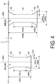
- FIG. 4 is diagram schematically illustrating an example of the end mold pin 60A and the middle mold pin 60B according to the present embodiment.
- the end mold pin 60A and the middle mold pin 60B both include a base portion 63 connected to the inner surface 53 of the sector mold 51, a trunk portion 61 connected to the base portion 63, and a tip portion 62 connected to the trunk portion 61.
- the end mold pin 60A is disposed about a center axis J60a.
- the base portion 63, the trunk portion 61, and the tip portion 62 of the end mold pin 60A have a circular shape.
- the center axis J60a conforms with a radial axis from the center of the annular mold formed by the plurality of sector molds 51.
- the middle mold pin 60B is disposed about a center axis J60b.
- the base portion 63, the trunk portion 61, and the tip portion 62 of the middle mold pin 60B have a circular shape.
- the center axis J60b conforms with a radial axis from the center of the annular mold formed by the plurality of sector molds 51.
- the base portion 63 decreases in diameter as a distance from the the inner surface 53 increases.
- the trunk portion 61 has a cylindrical shape.
- the tip portion 62 increases in diameter as a distance from the from the inner surface 53 increases.
- a first outer diameter D61a that represents the dimensions of the trunk portion 61 of the end mold pin 60A in a plane orthogonal to the center axis J60a is less than a second outer diameter D62a that represents the dimensions of the tip portion 62 of the end mold pin 60A. In other words, the second outer diameter D62a is greater than the first outer diameter D61a.
- a first outer diameter D61b that represents the dimensions of the trunk portion 61 of the middle mold pin 60B in a plane orthogonal to the center axis J60b is less than a second outer diameter D62b that represents the dimensions of the tip portion 62 of the middle mold pin 60B. In other words, the second outer diameter D62b is greater than the first outer diameter D61b.
- a first length H61a that represents the dimensions of the trunk portion 61 of the end mold pin 60A in a plane parallel with the center axis J60a is greater than a second length H62a that represents the dimensions of the tip portion 62 of the end mold pin 60A.
- a first length H61b that represents the dimensions of the trunk portion 61 of the middle mold pin 60B in a plane parallel with the center axis J60b is greater than a second length H62b that represents the dimensions of the tip portion 62 of the middle mold pin 60B.
- the first outer diameter D61a of the trunk portion 61 of the end mold pin 60A is greater than the first outer diameter D61b of the trunk portion 61 of the middle mold pin 60B.
- the trunk portion 61 of the end mold pin 60A is thicker than the trunk portion 61 of the middle mold pin 60B.
- the difference between the first outer diameter D61a of the end mold pin 60A and the first outer diameter D61b of the middle mold pin 60B is from 0.1 mm to 1.0 mm.
- the first outer diameter D61a of the end mold pin 60A is, for example, from 2.0 mm to 2.4 mm.
- the first outer diameter D61b of the middle mold pin 60B is from 0.1 mm to 1.0 mm less than the first outer diameter D61a.
- the difference between the first outer diameter D61a and the first outer diameter D61b is preferably from 0.2 mm to 0.5 mm.
- the second outer diameter D62a of the tip portion 62 of the end mold pin 60A is less than the second outer diameter D62b of the tip portion 62 of the middle mold pin 60B.
- the tip portion 62 of the end mold pin 60A is thinner than the tip portion 62 of the middle mold pin 60B.
- the difference between the second outer diameter D62a of the end mold pin 60A and the second outer diameter D62b of the middle mold pin 60B is from 0.2 mm to 1.5 mm.
- the second outer diameter D62a of the end mold pin 60A is, for example, from 3.5 mm to 4.5 mm.
- the second outer diameter D62b of the middle mold pin 60B is from 0.2 mm to 1.5 mm less than the second outer diameter D62a.
- the difference between the second outer diameter D62a and the second outer diameter D62b preferably is from 0.5 mm to 1.0 mm.
- the difference ⁇ a between the first outer diameter D61a and the second outer diameter D62a of the end mold pin 60A is less than the difference ⁇ b between the first outer diameter D61b and the second outer diameter D62b of the middle mold pin 60B.
- a length H60a of the end mold pin 60A is less than a length H60b of the middle mold pin 60B.
- the length H60a is the distance in the tire radial direction, which is parallel with the center axis J60a, from the boundary portion between the inner surface 53 of the sector mold 51 and the end mold pin 60A to the tip portion 62 of the end mold pin 60A.
- the length H60b is the distance in the tire radial direction, which is parallel with the center axis J60b, from the boundary portion between the inner surface 53 of the sector mold 51 and the middle mold pin 60B to the tip portion 62 of the middle mold pin 60B.
- the difference between the length H60a of the end mold pin 60A and the length H60b of the middle mold pin 60B is from 0.1 mm to 1.0 mm.
- the length H60a of the end mold pin 60A is, for example, from 9.0 mm to 10.0 mm.
- the length H60b of the middle mold pin 60B is from 0.1 mm to 1.0 mm greater than the length H60a.
- the difference between the length H60a and the length H60b preferably is from 0.1 mm to 0.5 mm.
- the first length H61a of the end mold pin 60A is less than the first length H61b of the middle mold pin 60B.
- the second length H62a of the end mold pin 60A may be equal to the second length H62b of the middle mold pin 60B or may be less than the second length H62b.
- the first outer diameter D61b, the second outer diameter D62b, and the length H60b are the same for the plurality of middle mold pins 60B (for example, 30).
- the mold 50 including the sector molds 51 and the side molds 52 is prepared.
- the step of preparing the sector molds 51 includes installing the mold pins 60, which includes the end mold pins 60A and the middle mold pins 60B, into the sector molds 51.
- the end mold pins 60A have a circular shape in a plane orthogonal to the center axis J60a
- the middle mold pins 60B have a circular shape in a plane orthogonal to the center axis J60b. Accordingly, in the installation of the mold pins 60 into the sector molds 51, excessive attention does not need to be paid to the orientation of the mold pins 60 with respect to the rotation direction about the center axis J60.
- the mold 50 is formed by assembling the sector molds 51 and the side molds 52 together. Adjacent sector molds 51 are brought in contact with each other.
- a green tire is disposed inside the mold 50.
- the sector molds 51 are brought in contact with the tread portion 3 of the green tire.
- the side molds 52 are brought in contact with the sidewall portions 5 of the green tire.
- the insertion holes 40 are formed in the tread portion 3 by the sector molds 51 that include the mold pins 60.
- the green tire disposed inside the mold 50 is vulcanized by being subjected to high heat and pressure.
- the vulcanization forms the tire 1B that includes the tread portion 3 in which the insertion holes 40 are formed.
- the vulcanized tire 1B is removed from the mold 50.
- the step of removing the tire 1B from the mold 50 includes releasing the tire 1B by moving the sector molds 51 that are in contact with the tire 1B outward in the tire radial direction.
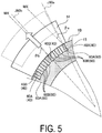
- FIG. 5 is a diagram schematically illustrating how the mold pins 60 are removed from the insertion holes 40. As illustrated in FIG. 5 , the sector molds 51 are moved outward in the tire radial direction to separate from the tire 1B, causing the mold pins 60 to be removed from the insertion holes 40 formed in the tread portion 3 of the tire 1B.
- the sector molds 51 move along a movement axis MX parallel with the radiation direction from the center axis of the tire 1B (the center axis of the annular mold).
- An angle ⁇ b between the movement axis MX of the sector mold 51 and the center axis J60b of the middle mold pin 60B is less than an angle ⁇ a between the movement axis MX of the sector mold 51 and the center axis J60a of the end mold pin 60A.
- the first outer diameter D61a of the trunk portion 61 of the end mold pin 60A is greater than the first outer diameter D61b of the trunk portion 61 of the middle mold pin 60B.
- the difference ⁇ a between the first outer diameter D61a of the trunk portion 61 and the second outer diameter D62a of the tip portion 62 of the end mold pin 60A is less than the difference ⁇ b between the first outer diameter D61b of the trunk portion 61 and the second outer diameter D62b of the tip portion 62 of the middle mold pin 60B.
- the first outer diameter D61b of the middle mold pin 60B is less than the first outer diameter D61a of the end mold pin 60A.
- the difference ⁇ b between the first outer diameter D61b and the second outer diameter D62b of the middle mold pin 60B is greater than the difference ⁇ a between the first outer diameter D61a and the second outer diameter D62a of the end mold pin 60A.
- the angle ⁇ b between the center axis J60b of the middle mold pin 60B and the movement axis MX of the sector mold 51 is less than the angle ⁇ a between the center axis J60a of the end mold pin 60A and the movement axis MX of the sector mold 51.
- FIG. 6 is a cross-sectional view schematically illustrating an example of the insertion holes 40 according to the present embodiment.
- the insertion holes 40 are formed by the mold pins 60.
- the insertion holes 40 include end insertion holes 40A formed by the end mold pins 60A and middle insertion holes 40B formed by the middle mold pins 60B.
- the end insertion hole 40A and the middle insertion hole 40B both include a first hole portion 41 formed by the trunk portion 61 of the mold pin 60, a second hole portion 42 formed by the tip portion 62, and a third hole portion 43 formed by the base portion 63.
- the trunk portion 61 forms the first hole portion 41.
- the tip portion 62 forms the second hole portion 42.
- the end insertion hole 40A is disposed about a center axis J40a.
- the first hole portion 41, the second hole portion 42, and the third hole portion 43 of the end insertion hole 40A have a circular shape.
- the center axis J40a conforms with a radial axis from the center of the tire 1B.
- the middle insertion hole 40B is disposed about a center axis J40b.
- the first hole portion 41, the second hole portion 42, and the third hole portion 43 of the middle insertion hole 40B have a circular shape.
- the center axis J40b conforms with a radial axis from the center of the tire 1B.
- the third hole portion 43 decreases in diameter as away from a contact patch 2 of the tread portion 3.
- the first hole portion 41 has a cylindrical shape.
- the second hole portion 42 increases in diameter as away from the contact patch 2.
- a first inner diameter D41a that represents the dimensions of the first hole portion 41 of the end insertion hole 40A in a plane orthogonal to the center axis J40a is less than a second inner diameter D42a that represents the dimensions of the second hole portion 42 of the end insertion hole 40A.
- the second inner diameter D42a is greater than the first inner diameter D41a.
- a first inner diameter D41b that represents the dimensions of the first hole portion 41 of the middle insertion hole 40B in a plane orthogonal to the center axis J40b is less than a second inner diameter D42b that represents the dimensions of the second hole portion 42 of the middle insertion hole 40B.
- the second inner diameter D42b is greater than the first inner diameter D41b.
- a first length H41a that represents the dimensions of the first hole portion 41 of the end insertion hole 40A in a plane parallel with the center axis J40a is greater than a second length H42a that represents the dimensions of the second hole portion 42 of the end insertion hole 40A.
- a first length H41b that represents the dimensions of the first hole portion 41 of the middle insertion hole 40B in a plane parallel with the center axis J40b is greater than a second length H42b that represents the dimensions of the second hole portion 42 of the middle insertion hole 40B.
- the first inner diameter D41a of the first hole portion 41 of the end insertion hole 40A is greater than the first inner diameter D41b of the first hole portion 41 of the middle insertion hole 40B.
- the first hole portion 41 of the end insertion hole 40A is larger than the first hole portion 41 of the middle insertion hole 40B.
- the difference between the first inner diameter D41a of the end insertion hole 40A and the first inner diameter D41b of the middle insertion hole 40B is from 0.1 mm to 1.0 mm.
- the difference between the first inner diameter D41a and the first inner diameter D41b preferably is from 0.2 mm to 0.5 mm.
- the second inner diameter D42a of the second hole portion 42 of the end insertion hole 40A is less than the second inner diameter D42b of the second hole portion 42 of the middle insertion hole 40B.
- the second hole portion 42 of the end insertion hole 40A is thinner than the second hole portion 42 of the middle insertion hole 40B.
- the difference between the second inner diameter D42a of the end insertion hole 40A and the second inner diameter D42b of the middle insertion hole 40B is from 0.2 mm to 1.5 mm.
- the difference between the second inner diameter D42a and the second inner diameter D42b preferably is from 0.5 mm to 1.0 mm.
- a difference ⁇ c between the first inner diameter D41a and the second inner diameter D42a of the end insertion hole 40A is less than a difference ⁇ d between the first inner diameter D41b and the second inner diameter D42b of the middle insertion hole 40B.
- a length H40a of the end insertion hole 40A is less than a length H40b of the middle insertion hole 40B.
- the length H40a is the distance in the tire radial direction, which is parallel with the center axis J40a, from the contact patch 2 to the bottom surface of the second hole portion 42 of the end insertion hole 40A.
- the length H40b is the distance in the tire radial direction, which is parallel with the center axis J40b, from the contact patch 2 to the bottom surface of the second hole portion 42 of the middle insertion hole 40B.
- the difference between the length H40a of the end insertion hole 40A and the length H40b of the middle insertion hole 40B is from 0.1 mm to 1.0 mm.
- the difference between the length H40a and the length H40b preferably is from 0.1 mm to 0.5 mm.
- the first length H41a of the end insertion hole 40A is less than the first length H41b of the middle insertion hole 40B.
- the second length H42a of the end insertion hole 40A may be equal to the second length H42b of the middle insertion hole 40B or may be less than the second length H42b.
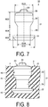
- FIG. 7 is a side view illustrating an example of a stud pin 30 according to the present embodiment.
- FIG. 8 is a cross-sectional view illustrating an example of the stud pin 30 inserted into the insertion hole 40.
- the stud pin 30 includes a body portion 31, a bottom flange portion 32, and a tip portion 35.
- the body portion 31 is supported by the bottom flange portion 32.
- the tip portion 35 is supported by the body portion 31.
- the bottom flange portion 32 and the body portion 31 are disposed in the insertion hole 40 provided in the tread portion 3.
- the tip portion 35 is disposed in a manner so as to project from the contact patch 2 of the tread portion 3.
- the body portion 31 includes an upper flange portion 33 and a middle portion 34.
- the body portion 31 and the bottom flange portion 32 are integrated (one member).
- the stud pin 30 is disposed is a region around a center axis J30 that passes through the tip portion 35.
- the body portion 31, the bottom flange portion 32, and the tip portion 35 have a circular shape.
- the stud pin 30 is a circular pin.
- the bottom flange portion 32 and the upper flange portion 33 are circular flanges.
- the middle portion 34 has a cylindrical shape.
- An outer diameter D34 that represents the dimensions of the middle portion 34 in a plane orthogonal to the center axis J30 is less than an outer diameter D33 of the upper flange portion 33.
- the outer diameter D34 of the middle portion 34 is less than an outer diameter D32 of the bottom flange portion 32.
- the outer diameter D33 of the upper flange portion 33 is less than the outer diameter D32 of the bottom flange portion 32.
- a height H34 that represents the dimensions of the middle portion 34 in a plane parallel with the center axis J30 is less than a height H33 of the upper flange portion 33.
- the height H34 of the middle portion 34 is greater than a height H32 of the bottom flange portion 32.
- the height H33 of the upper flange portion 33 is greater than the height H32 of the bottom flange portion 32.
- the body portion 31 of the stud pin 30 is disposed in the first hole portion 41 of the insertion hole 40.
- the bottom flange portion 32 of the stud pin 30 is disposed in the second hole portion 42 of the insertion hole 40.
- FIG. 9 is a cross-sectional view illustrating a portion of the studded tire 1 according to the present embodiment.
- FIG. 9 illustrates a meridian cross-section passing through a rotation axis AX of the studded tire 1.
- FIG. 10 is a plan view illustrating an example of the tread portion 3 of the studded tire 1 according to the present embodiment.
- the studded tire 1 rotates about the rotation axis AX.
- the tire circumferential direction includes the tire rotation direction about the rotation axis AX.
- the tire lateral direction includes the direction parallel with the rotation axis AX.
- the tire radial direction includes the radiation direction from the rotation axis AX.
- An equator line CL of the studded tire 1 is the center line which passes through the center of the studded tire 1 in the tire lateral direction.
- the studded tire 1 is a winter tire (snow tire) provided with the stud pins 30.
- the studded tire 1 may also be referred to as a spike tire 1.
- the studded tire 1 includes the tire 1B and the stud pins 30 provided in the tread portion 3 of the tire 1B.
- the tire 1B is a pneumatic tire.
- the stud pins 30 are inserted into the insertion holes 40 formed in the tread portion 3.
- the tire 1B includes the contact patch 2, the tread portion 3 formed by the plurality of sector molds 51 disposed in the tire circumferential direction, and the plurality of insertion holes 40 formed in the tread portion 3 by the mold pins 60 disposed on the inner surface 53 of each of the sector molds 51 that opposes the tread portion 3 and project inward in the tire radial direction.
- the stud pins 30 are inserted into the insertion holes 40.
- the tire 1B includes bead portions 4 that connect to the rim and sidewall portions 5 that join the tread portion 3 and the bead portions 4.
- the contact patch 2 comes into contact with the road surface (ground) when the tire 1 runs.
- the tire 1B includes a carcass 6 and an innerliner 7.
- the carcass 6 is the framework of the tire 1B and maintains the shape of the tire 1B.
- the innerliner 7 is disposed facing the cavity of the tire 1B.
- the carcass 6 and the innerliner 7 are disposed in the tread portion 3, the bead portions 4, and the sidewall portions 5.
- the bead portions 4 each include a bead core 11 and a bead filler 12.
- the bead cores 11 fix the tire 1 to the rim.
- the bead cores 11 are disposed on either side of the equator line CL of the tire 1B in the tire lateral direction.
- the bead cores 11 include a plurality of high-carbon steel annular members bundled together.
- the bead cores 11 are disposed so as to surround the rotation axis AX.
- the bead fillers 12 increase the rigidity of the bead portions 4.
- the tread portion 3 includes a belt 14 and the tread rubber 15.
- the belt 14 includes a layer of belt members.
- the belt 14 is disposed on the outer side of the carcass 6 in the tire radial direction.
- the belt 14 secures the carcass 6 and increases the rigidity of the tread portion 3.
- a tread pattern is formed in the tread rubber 15.
- the tread rubber 15 is disposed on the outer side of the carcass 6 and the belt 14 in the radial direction.
- the contact patch 2 is disposed in the tread rubber 15.
- the sidewall portions 5 each include a sidewall rubber 16.
- the sidewall portions 5 are disposed on either side of the equator line CL in the tire lateral direction.
- the carcass 6 is disposed in a toroidal form between the bead cores 11 on either side of the equator line CL in the tire lateral direction.
- the carcass 6 is folded back at both end portions so as to surround the bead fillers 12.
- Grooves 20 are formed in the tread rubber 15.
- the tread pattern is formed by the grooves 20.
- the grooves 20 include main grooves 21 formed in the tire circumferential direction and lug grooves 22 formed in the tire lateral direction (see FIG. 10 ).
- the tread rubber 15 is defined by the main grooves 21 and the lug grooves 22, thus forming blocks 23.
- the contact patch 2 includes the surfaces of the blocks 23.
- the studded tire 1 is provided with stud pins 30.
- the tire 1B includes a plurality of insertion holes 40 into which the stud pins 30 are inserted.
- the insertion holes 40 are formed in the tread portion 3 of the tire 1B.
- the insertion holes 40 are formed in the blocks 23 of the tread rubber 15.
- the stud pins 30 are at least partially disposed in the insertion holes 40.
- the stud pins 30 are supported by the inner surface of the insertion holes 40 so as to partially project from the contact patch 2 of the tread portion 3.
- the tread portion 3 includes a plurality of insertion holes 40 in the tire circumferential direction.
- the insertion holes 40 include the end insertion holes 40A provided in end regions 73A in the tire circumferential direction of a predetermined region 73 of the tread portion 3 formed by one sector mold 51, and the middle insertion holes 40B formed in a middle region 73B of the tread portion 3 between the end region 73A on one side and the end region 73A on the other side.
- the predetermined region 73 is a region formed by the contact of one sector mold 51.
- a boundary portion 70 between two adjacent predetermined regions 73 opposes the boundary portion of two adjacent sector molds 51.
- the end portions of the predetermined regions 73 in the tire circumferential direction include the boundary portion 70.
- a line can form in the tread portion 3 due to a gap between two adjacent sector molds 51.
- the rubber can enter the gap between two adjacent sector molds 51 and form a line.
- the boundary portion 70 may include such a line of rubber.
- Each end region 73A is a region spanning in the tire circumferential direction from the end portion of the predetermined region 73 to a position located a predetermined distance from the end portion toward the center of the predetermined region 73.
- the end regions 73A include the end region 73A that includes the end portion on one side of the predetermined region 73 and the end region 73A that includes the end portion on the other side of the predetermined region 73, with respect to the tire circumferential direction.
- the middle region 73B is the region of the predetermined region 73 between the end region 73A on one side and the end region 73A on the other side.
- the end insertion holes 40A are the insertion holes 40 provided in the predetermined region 73 of the tread portion 3 disposed closest to the end portions of the predetermined region 73 with respect to the tire circumferential direction.
- the insertion hole 40 located closest to the end portion on one side of the predetermined region 73 and the insertion hole 40 located closest to the end portion on the other side of the predetermined region 73 are end insertion holes 40A.
- Two end insertion holes 40A are formed in one predetermined region 73.
- the middle insertion holes 40B are the insertion holes 40 other than the end insertion holes 40A formed in the predetermined region 73 of the tread portion 3.
- the middle insertion holes 40B are the insertion holes 40 other than the end insertion holes 40A formed in the predetermined region 73 of the tread portion 3.
- two are end insertion holes 40A and 30 are middle insertion holes 40B.
- the first inner diameter D41b, the second inner diameter D42b, and the length H40b are the same for the plurality of middle insertion holes 40B (for example, 30).
- the stud pins 30 include the body portion 31 and the bottom flange portion 32. Thus, the stud pins 30 are sufficiently prevented from falling out of the insertion holes 40.
- the end mold pins 60A are defined as the mold pins 60 provided in the sector mold 51 that are located closest to the end portions of the sector mold 51 with respect to the tire circumferential direction.
- mold pins 60 provided on the inner surface 53 within a predetermined range (for example, 5 cm) from the end portion of the inner surface 53 may also be defined as end mold pins 60A.
- three or more end mold pins 60A can be provided in one sector mold 51.
- the end insertion holes 40A are defined as the insertion holes 40 provided in the tread portion 3 disposed closest to the boundary portion 70 in the tire circumferential direction.
- insertion holes 40 formed within a predetermined range (for example, 5 cm) from the boundary portion 70 may also be defined as end insertion holes 40A.
- three or more end insertion holes 40A can be formed in one predetermined region 73.
- FIG. 11 is a diagram schematically illustrating an example of the tread portion 3 according to the present embodiment.
- the tread portion 3 includes a first region AR1 on one side of the equator line CL in the tire lateral direction and a second region AR2 on the other side.
- the insertion holes 40 are formed in the first region AR1 and the second region AR2.
- the sector molds 51 include the mold pins 60 for forming the insertion holes 40 in the first region AR1 and the mold pins 60 for forming the insertion holes 40 in the second region AR2.
- the sector molds 51 form the insertion holes 40 illustrated in FIG. 11 .
- the insertion hole 40 located closest to the boundary portion 70, which is the end portion of the predetermined region 73, in the tire circumferential direction may be defined as the end insertion hole 40A.
- the insertion hole 40 located closest to the boundary portion 70, which is the end portion of the predetermined region 73, in the tire circumferential direction may be defined as the end insertion hole 40A.
- an insertion hole 401, an insertion hole 402, and an insertion hole 403 are formed in the predetermined region 73.
- the insertion hole 401 and the insertion hole 402 are formed in the first region AR1 of the predetermined region 73.
- the insertion hole 403 is formed in the second region AR2 of the predetermined region 73.
- the insertion hole 401 is located closest to the boundary portion 70, the insertion hole 402 is located closest to the boundary portion 70 after the insertion hole 401, and the insertion hole 403 is located farthest from the boundary portion 70.
- the insertion hole 401 is located closest to the boundary portion 70 and is thus defined as an end insertion hole 40A.
- the insertion hole 403 is located further away from the boundary portion 70 than the insertion hole 402.
- the insertion hole 403 is located closest to the boundary portion 70 of the insertion holes 40 formed in the second region AR2. Accordingly, the insertion hole 403 is defined as an end insertion hole 40A.
- the insertion hole 402 is defined as a middle insertion hole 40B.
- the insertion hole 401 (end insertion hole 40A) is formed by the mold pin 60 located closest to the end portion of the inner surface 53 of the sector mold 51 in the tire circumferential direction of the mold pins 60 for forming the insertion holes 40 in the first region AR1.
- the insertion hole 403 (end insertion hole 40A) is formed by the mold pin 60 located closest to the end portion of the inner surface 53 of the sector mold 51 in the tire circumferential direction of the mold pins 60 for forming the insertion holes 40 in the second region AR2.
- the stud pins 30 are prevented from falling out from the first region AR1 and the second region AR2. Thus, a decrease in the running performance of the studded tire 1 is suppressed.
- the mold pins 60 are classified into two types: the end mold pins 60A and the middle mold pins 60B. This configuration minimizes the types of mold pins 60 to allow the mold 50 to be easily manufactured, which suppresses an increase in the cost of the mold 50.
- the sector molds 51 may be provided with three or more types of mold pins 60 with varying first outer diameters D61 of the trunk portion 61. In embodiments in which three or more mold pins 60 with varying first outer diameters D61 of the trunk portion 61 are disposed in the tire circumferential direction, a plurality of mold pins 60 may be provided with the first outer diameter D61 of the mold pins 60 gradually increasing from the central portion to the end portion of the inner surface 53.
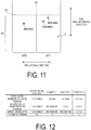
- FIG. 12 is a table showing results of evaluation tests for studded tires 1 according to the embodiments of the present invention.
- FIG. 12 shows results of evaluation tests which involved finding the number of insertion holes 40 around which cracking occurred (number of cracks) out of the insertion holes 40 formed in the studded tire 1.
- Tires 1B with a tire size of 205/55R16 were vulcanization molded using the mold 50. Thereafter, the sector molds 51 of the mold 50 were moved to release the tire 1B. The number of cracks formed around the insertion holes 40 when the mold pins 60 were removed from the insertion holes 40 was counted. Note that 20 tires 1B were vulcanization molded. One hundred twenty insertion holes 40 were formed in each tire 1B. In each tire 1B, the number of insertion holes 40 disposed near the boundary portion 70 was 32. Thus, the total number of insertion holes 40 disposed near the boundary portion 70 was 640 (32 ⁇ 20).
- Example 1 refers to an example in which the mold pins 60 provided on the sector molds 51 all have the same dimensions.
- Example 1 Example 2, and Example 3 are examples in which the mold pins 60 provided on the sector molds 51 include end mold pins 60A and middle mold pins 60B.
- the first outer diameter D61a of the end mold pins 60A is 0.3 mm greater than the first outer diameter D61b of the middle mold pins 60B.
- the second outer diameter D62a of the end mold pins 60A is 0.5 mm less than the second outer diameter D62b of the middle mold pins 60B.
- Example 3 in addition to the conditions of Example 2, the length H60a of the end mold pins 60A is 0.2 mm less than the length H60b of the middle mold pins 60B.
- cracking was found in a region around 30 insertion holes 40 out of the 640 insertion holes 40.
- Example 1 cracking was found in a region around ten insertion holes 40 out of the 640 insertion holes 40.
- Example 2 cracking was found in a region around seven insertion holes 40 out of the 640 insertion holes 40.
- Example 3 cracking was found in a region around three insertion holes 40 out of the 640 insertion holes 40.
Landscapes
- Engineering & Computer Science (AREA)
- Mechanical Engineering (AREA)
- Physics & Mathematics (AREA)
- Health & Medical Sciences (AREA)
- Oral & Maxillofacial Surgery (AREA)
- Thermal Sciences (AREA)
- Moulds For Moulding Plastics Or The Like (AREA)
- Heating, Cooling, Or Curing Plastics Or The Like In General (AREA)
- Tyre Moulding (AREA)
- Tires In General (AREA)
Abstract
Description
- The present invention relates to a tire mold and a pneumatic tire.
- Known winter tires include studded tires that include stud pins. Stud pins are inserted in insertion holes provided in the tread portion of the tire.
Patent Document 1 describes a studded tire manufactured via the steps including vulcanizing a green tire in a mold that includes projection portions that include mold pins, removing the vulcanized tire from the mold, and inserting the stud pins into the insertion holes formed in the tire by the projection portions. The mold includes a plurality of sector molds that form the tread portion of the tire and side molds that form the sidewall portions of the tire. The projection portions for forming the insertion holes are provided on sector molds. - Patent Document 1: Japanese Patent No.
5513345B - After vulcanization of a tire, cracks can form in the region around the insertion holes, caused when the projection portions are removed from the insertion holes. Such cracks can cause the holding force that holds the stud pins in the insertion holes to be decreased, spoil the appearance of the tire, and cause the performance of the studded tire to be decreased.
- An aspect of the present invention has an object of providing a tire mold and a pneumatic tire capable of suppressing cracking when forming insertion holes.
- A first aspect of the present invention provides a tire mold for forming a tire that includes insertion holes into which stud pins are inserted, the tire mold comprising:
- a plurality of sector molds for forming a tread portion of the tire, the plurality of sector molds being disposed in a tire circumferential direction; and
- a plurality of mold pins for forming the insertion holes in the tread portion, the plurality of mold pins being provided on inner surfaces of the plurality of sector molds that oppose the tread portion and projecting inward in a tire radial direction;
- the stud pins each comprising a body portion and a bottom flange portion;
- the insertion holes each comprising a first hole portion with a first inner diameter where the body portion of the stud pin is disposed and a second hole portion with a second inner diameter greater than the first inner diameter where the bottom flange portion of the stud pin is disposed;
- the plurality of mold pins each comprising a trunk portion with a first outer diameter for forming the first hole portion and a tip portion with a second outer diameter greater than the first outer diameter for forming the second hole portion; and
- the first outer diameter of the trunk portion of an end mold pin of the plurality of mold pins provided in an end region in the tire circumferential direction of each of the plurality of sector molds being greater than the first outer diameter of the trunk portion of a middle mold pin of the plurality of mold pins provided in a middle region of each of the plurality of sector molds, the middle region being located between the end region on one side and the end region on the other side in the tire circumferential direction.
- According to the first aspect of the present invention, the first outer diameter of the end mold pin is greater than the first outer diameter of the middle mold pin. As a result, when the sector molds are moved outward in the tire radial direction to release the tire and the end mold pins are removed from the insertion holes formed in the tire, cracking caused by removal of the end mold pins is suppressed.
- The angle formed by the movement axis of the sector mold and the center axis of the middle mold pin is small when the sector molds are moved outward in the tire radial direction. The angle formed by the movement axis of the sector mold and the center axis of the end mold pin is large.
- The first outer diameter of the trunk portion of the mold pin being small includes in its meaning the difference between the first outer diameter of the trunk portion of the mold pin and the second outer diameter of the tip portion of the mold pin being great. The first outer diameter of the trunk portion of the mold pin being large includes in its meaning the difference between the first outer diameter of the trunk portion of the mold pin and the second outer diameter of the tip portion of the mold pin being small.
- If the difference between the first outer diameter and the second outer diameter of the end mold pin having a center axis that forms a large angle with the movement axis of the sector mold is great, when the end mold pin is removed from the insertion hole, the stress acting upon the rubber in a region around the insertion hole is great. As a result, cracking is highly likely to occur in a region around the insertion hole.
- By the first outer diameter of the trunk portion of the end mold pin being great and the difference between the first outer diameter of the trunk portion of the end mold pin and the second outer diameter of the tip portion of the end mold pin being small, even when the end mold pin with a center axis that forms a large angle with the movement axis of the sector mold is removed from the insertion hole, the stress acting upon the rubber in a region around the insertion hole is suppressed. As a result, cracking in regions around the insertion holes formed by the end mold pins is suppressed.
- The first outer diameter of the middle mold pin is small and the difference between the first outer diameter and the second outer diameter of the middle mold pin is greater, however the angle formed by the center axis of the middle mold pin and the movement axis of the sector mold is small. As a result, when the middle mold pin is removed from the insertion hole, the stress acting upon the rubber in a region around the insertion hole is suppressed. Accordingly, cracking in regions around the insertion holes formed by the middle mold pins is suppressed.
- By suppressing cracking, a decrease in the holding force of the stud pins provided by the insertion holes and spoiling of the appearance of the studded tire, which are caused by such cracking, can be prevented. Thus, a decrease in the performance of the studded tire is prevented.
- Additionally, according to the first aspect of the present invention, the mold pin comprising the trunk portion with the first outer diameter and the tip portion with the second outer diameter has a circular shape in a plane orthogonal to the center axis of the mold pin. Accordingly, in the installation of the mold pins into the sector molds, excessive attention does not need to be paid to the orientation of the mold pins with respect to the rotation direction about the center axis. Thus, complexity of the labor involved is suppressed. Additionally, cracking conditions changing due to the orientation of the mold pin is suppressed.
- In the first aspect of the present invention, a difference between the first outer diameter of the end mold pin and the first outer diameter of the middle mold pin may be from 0.1 mm to 1.0 mm.
- This suppresses crack and thus maintains the performance of the studded tire. If the difference is less than 0.1 mm, cracking in a region around the insertion hole formed by the end mold pin may not be sufficiently suppressed. If the difference is greater than 1.0 mm, the holding force of the stud pin provided by the insertion hole formed by the end mold pin is likely to decrease.
- In the first aspect of the present invention, the second outer diameter of the tip portion of the end mold pin may be less than the second outer diameter of the tip portion of the middle mold pin.
- This effectively suppresses crack and thus maintains the performance of the studded tire. The second outer diameter of the tip portion of the mold pin being great includes in its meaning the difference between the first outer diameter of the trunk portion of the mold pin and the second outer diameter of the tip portion of the mold pin being small. The second outer diameter of the tip portion of the mold pin being small includes in its meaning the difference between the first outer diameter of the trunk portion of the mold pin and the second outer diameter of the tip portion of the mold pin being large. By the second outer diameter of the tip portion of the end mold pin being small and the difference between the first outer diameter of the trunk portion of the end mold pin and the second outer diameter of the tip portion of the end mold pin being small, even when the end mold pin with a center axis that forms a large angle with the movement axis of the sector mold is removed from the insertion hole, the stress acting upon the rubber in a region around the insertion hole is suppressed. As a result, cracking in regions around the insertion holes formed by the end mold pins is suppressed.
- In the first aspect of the present invention, a difference between the second outer diameter of the end mold pin and the second outer diameter of the middle mold pin may be from 0.2 mm to 1.5 mm.
- This suppresses crack and thus maintains the performance of the studded tire. If the difference is less than 0.2 mm, cracking in a region around the insertion hole formed by the end mold pin may not be sufficiently suppressed. If the difference is greater than 1.5 mm, the holding force of the stud pin provided by the insertion hole formed by the end mold pin is likely to decrease.
- In the first aspect of the present invention, a length of the end mold pin may be less than a length of the middle mold pin.
- As a result, cracking is effectively suppressed. By the length of the end mold pin being small, even when the end mold pin with a center axis that forms a large angle with the movement axis of the sector mold is removed from the insertion hole, the stress acting upon the rubber in a region around the insertion hole is suppressed. As a result, cracking in regions around the insertion holes formed by the end mold pins is suppressed.
- In the first aspect of the present invention, a difference between the length of the end mold pin and the length of the middle mold pin may be from 0.1 mm to 1.0 mm.
- This suppresses crack and thus maintains the performance of the studded tire. If the difference is less than 0.1 mm, cracking in a region around the insertion hole formed by the end mold pin may not be sufficiently suppressed. If the difference is greater than 1.0 mm, the holding force of the stud pin provided by the insertion hole formed by the end mold pin is likely to decrease.
- In the first aspect of the present invention, the end mold pin may be a mold pin of the plurality of mold pins provided on each of the plurality of sector molds located closest to an end portion of the sector mold in the tire circumferential direction.
- As a result, cracking in a region around the insertion hole formed by the end mold pin with a center axis that forms the greatest angle with the movement axis of the sector mold is suppressed.
- In the first aspect of the present invention,
the tread portion may comprises a first region on one side of an equator line of the tire in a tire lateral direction and a second region on the other side, the plurality of mold pins may comprise a plurality of mold pins for forming the insertion holes in the first region and a plurality of mold pins for forming the insertion holes in the second region, and
the end mold pin may be a mold pin of the plurality of mold pins for forming the insertion holes in the first region and the second region located closest to an end portion of each of the plurality of sector molds in the tire circumferential direction. - As a result, cracking in a region around the insertion holes formed in the first region and cracking in a region around the insertion holes formed in the second region are suppressed. Thus, the stud pins in the first region and the second region are prevented from falling out and a decrease in the running performance of the studded tire is suppressed.
- In the first aspect of the present invention, the middle mold pin may be a mold pin of the plurality of mold pins provided on the plurality of sector molds other than the end mold pins, and the first outer diameter, the second outer diameter, and the length may be the same for all of the middle mold pins.
- As a result, it is sufficient to prepare only two types of mold pins, the end mold pin and the middle mold pin, thus suppressing the cost of the tire mold.
- A second aspect of the present invention provides a pneumatic tire, comprising:
- a tread portion formed by a plurality of sector molds disposed in a tire circumferential direction;
- a plurality of insertion holes into which stud pins are inserted, the plurality of insertion holes being formed in the tread portion by mold pins provided on inner surfaces of the plurality of sector molds that oppose the tread portion and
- projecting inward in a tire radial direction;
- the stud pins each comprising a body portion and a bottom flange portion;
- the plurality of insertion holes each comprising a first hole portion with a first inner diameter where the body portion of the stud pin is disposed and a second hole portion with a second inner diameter greater than the first inner diameter where the bottom flange portion of the stud pin is disposed; and the first inner diameter of the first hole portion of an end insertion hole of the plurality of insertion holes formed in an end region in the tire circumferential direction of a predetermined region, which is formed by one of the plurality of sector molds, of the tread portion being greater than the first inner diameter of the first hole portion of a middle insertion hole of the plurality of insertion holes formed in a middle region of the tread portion, the middle region being located between the end region on one side and the end region on the other side in the tire circumferential direction.
- According to the second aspect of the present invention, the first inner diameter of the end insertion hole is greater than the first inner diameter of the middle insertion hole. As a result, when the sector molds are moved outward in the tire radial direction to release the tire and the mold pins are removed from the insertion holes formed in the tire, cracking caused by removal of the mold pins is suppressed. Thus, a decrease in the performance of the pneumatic tire is prevented.
- Additionally, according to the second aspect of the present invention, the insertion hole comprising the first hole portion with the first inner diameter and the second hole portion with the second inner diameter has a circular shape in a plane orthogonal to the center axis of the insertion hole. Accordingly, in forming the insertion holes, excessive attention does not need to be paid to the orientation of the insertion holes with respect to the rotation direction about the center axis. Thus, complexity of the labor involved is suppressed. Additionally, cracking conditions changing due to the orientation of the insertion hole is suppressed.
- In the second aspect of the present invention, a difference between the first inner diameter of the end insertion hole and the first inner diameter of the middle insertion hole may be from 0.1 mm to 1.0 mm.
- This suppresses crack and thus maintains the performance of the studded tire. If the difference is less than 0.1 mm, cracking in a region around the end insertion hole may not be sufficiently suppressed. If the difference is greater than 1.0 mm, the holding force of the stud pin provided by the end insertion hole is likely to decrease.
- In the second aspect of the present invention, the second inner diameter of the second hole portion of the end insertion hole may be less than the second inner diameter of the second hole portion of the middle insertion hole.
- As a result, cracking is more effectively suppressed.
- In the second aspect of the present invention, a difference between the second inner diameter of the end insertion hole and the second inner diameter of the middle insertion hole may be from 0.2 mm to 1.5 mm.
- This suppresses crack and thus maintains the performance of the studded tire. If the difference is less than 0.2 mm, cracking in a region around the end insertion hole may not be sufficiently suppressed. If the difference is greater than 1.5 mm, the holding force of the stud pin provided by the end insertion hole is likely to decrease.
- In the second aspect of the present invention, a length of the end insertion hole may be less than a length of the middle insertion hole.
- As a result, cracking is effectively suppressed.
- In the second aspect of the present invention, a difference between the length of the end insertion hole and the length of the middle insertion hole may be from 0.1 mm to 1.0 mm.
- This suppresses crack and thus maintains the performance of the studded tire. If the difference is less than 0.1 mm, cracking in a region around the end insertion hole may not be sufficiently suppressed. If the difference is greater than 1.0 mm, the holding force of the stud pin provided by the end insertion hole is likely to decrease.
- In the second aspect of the present invention, the end insertion hole may be an insertion hole of the plurality of insertion holes provided in the predetermined region located closest to an end portion of the predetermined region in the tire circumferential direction.
- As a result, cracking in a region around the end insertion hole with a center axis that forms the greatest angle with the movement axis of the sector mold is suppressed.
- In the second aspect of the present invention, the tread portion may comprise a first region on one side of a tire equator line in a tire lateral direction and a second region on the other side,
the plurality of insertion holes may be formed in the first region and the second region, and the end insertion hole may be an insertion hole of the plurality of insertion holes formed in the first region located closest to an end portion of the predetermined region in the tire circumferential direction and may be an insertion hole of the plurality of insertion holes formed in the second region located closest to an end portion of the predetermined region in the tire circumferential direction. - As a result, cracking in a region around the insertion holes formed in the first region and cracking in a region around the insertion holes formed in the second region are suppressed. Thus, the stud pins in the first region and the second region are prevented from falling out and a decrease in the running performance of the studded tire is suppressed.
- In the second aspect of the present invention, the middle insertion hole may be an insertion hole of the plurality of insertion holes provided in the tread portion other than the end mold pins, and
the first inner diameter, the second inner diameter, and the length may be the same for all of the middle insertion holes. - As a result, it is sufficient to prepare only two types of insertion holes, the end insertion hole and the middle insertion hole, thus suppressing the cost of the pneumatic tire.
- An aspect of the present invention provides a tire mold and a pneumatic tire capable of suppressing cracking in a region around insertion holes.
-
- FIG. 1
- is a cross-sectional view schematically illustrating a portion of a mold according to a first embodiment.
- FIG. 2
- is a diagram schematically illustrating an example of the operation of the mold according to the first embodiment.
- FIG. 3
- is diagram schematically illustrating an example of a sector mold according to the first embodiment.
- FIG. 4
- is diagram schematically illustrating an example of a mold pin according to the first embodiment.
- FIG. 5
- is diagram schematically illustrating an example of the operation of the sector mold according to the first embodiment.
- FIG. 6
- is a cross-sectional view schematically illustrating an example of the insertion holes according to the first embodiment.
- FIG. 7
- is a side view illustrating an example of a stud pin according to the first embodiment.
- FIG. 8
- is a side view illustrating an example of the stud pin and the insertion hole according to the first embodiment.
- FIG. 9
- is a cross-sectional view illustrating an example of a studded tire according to the first embodiment.
- FIG. 10
- is a plan view illustrating an example of the studded tire according to the first embodiment.
- FIG. 11
- is a diagram schematically illustrating an example of a tread portion of a studded tire according to a second embodiment.
- FIG. 12
- is a table showing results of evaluation tests for the conventional example and examples.
- Embodiments according to the present invention will be described with reference to the appended drawings. However, the present invention is not limited to these embodiments. Constituents of the embodiments described below can be combined with one another as appropriate. In addition, some of the constituents may not be used in some cases.
- A first embodiment will now be described.
FIG. 1 is a cross-sectional view schematically illustrating a portion of atire mold 50 according to the present embodiment.FIG. 2 is a diagram schematically illustrating an example of the operation of themold 50 according to the present embodiment. - The
mold 50 forms atire 1B that includes insertion holes 40 into which stud pins are inserted. Themold 50 is a vulcanization mold. A green tire is disposed inside themold 50. The green tire is supported by themold 50 when vulcanized. - The
mold 50 includes a plurality ofsector molds 51 for forming atread portion 3 of thetire 1B disposed in the tire circumferential direction, andside molds 52 for formingsidewall portions 5 of thetire 1B. - Additionally, the
mold 50 includes a plurality of mold pins 60 for forming the insertion holes 40 in thetread portion 3. The mold pins 60 are disposed on aninner surface 53 of each of thesector molds 51 that opposes thetread portion 3 of thetire 1B and project inward in the tire radial direction. - The
tread portion 3 is formed by the plurality ofsector molds 51 disposed in the tire circumferential direction. The plurality of insertion holes 40 into which the stud pins are inserted are formed in thetread portion 3 by the mold pins 60. The mold pins 60 are disposed on theinner surface 53 of each of thesector molds 51 that opposes thetread portion 3 and project inward in the tire radial direction. - Note that, although not illustrated, the
sector molds 51 include a plurality of projection portions for forming grooves in thetread portion 3. A tread pattern is formed in thetire 1B by the projection portions provided on theinner surface 53 of each of thesector molds 51. - The
side molds 52 include anupper side mold 52A and alower side mold 52B. Thetire 1B is disposed between theupper side mold 52A and thelower side mold 52B. - As illustrated in
FIG. 2 , thesector molds 51 are arranged in the tire circumferential direction. In the example illustrated inFIG. 2 , themold 50 includes ninesector molds 51. - The
sector molds 51 are members of an annular mold divided in the tire circumferential direction. As illustrated by the arrow inFIG. 2 , thesector molds 51 are moveable in the tire radial direction. Thesector molds 51 are brought into contact with thetread portion 3 of thetire 1B by being moved inward in the tire radial direction. Thesector molds 51 are released from thetread portion 3 of thetire 1B by being moved outward in the tire radial direction. Thesector molds 51 move inward in the tire radial direction to form an integrated annular mold. Thesector molds 51 move outward in the tire radial direction to become divided. - Note that
FIG. 2 illustrates an example in which the annular mold is divided into nine sections, i.e. includes ninesector molds 51. The annular mold may be divided into eight sections, for example. - The
upper side mold 52A is released from thesidewall portion 5 of thetire 1B by being moved upward. Theupper side mold 52A is brought into contact with thesidewall portion 5 of thetire 1B by being moved downward. Thelower side mold 52B is released from thesidewall portion 5 of thetire 1B by being moved downward. Thelower side mold 52B is brought into contact with thesidewall portion 5 of thetire 1B by being moved upward. -
FIG. 3 is diagram schematically illustrating an example of asector mold 51 according to the present embodiment. Thesector mold 51 includes the mold pins 60 arranged in the tire circumferential direction. The mold pins 60 include end mold pins 60A and middle mold pins 60B. The end mold pins 60A are provided inend regions 51A of theinner surface 53 of thesector mold 51 with respect to the tire circumferential direction. The middle mold pins 60B are provided in amiddle region 51B of theinner surface 53 of thesector mold 51 between theend regions 51A. - Each
end region 51A is a region spanning in the tire circumferential direction from the end portion of theinner surface 53 of thesector mold 51 to a position located a predetermined distance from the end portion toward the center of theinner surface 53. Theend regions 51A include theend region 51A that includes the end portion on one side of theinner surface 53 and theend region 51A that includes the end portion on the other side of theinner surface 53, with respect to the tire circumferential direction. Themiddle region 51B is the region of theinner surface 53 between theend region 51A on one side and theend region 51A on the other side. - In the present embodiment, the end mold pins 60A are the mold pins 60 provided on the
sector mold 51 that are located closest to the end portions of thesector mold 51 with respect to the tire circumferential direction. In other words, among the mold pins 60 disposed in the tire circumferential direction, themold pin 60 located closest to the end portion on one side of theinner surface 53 and themold pin 60 located closest to the end portion on the other side of theinner surface 53 are end mold pins 60A. Onesector mold 51 includes two end mold pins 60A. - The middle mold pins 60B are the mold pins 60 other than the
end mold pins 60A provided on thesector mold 51. For example, in a configuration in which onesector mold 51 includes 32 mold pins 60, of the 32 mold pins 60, two are end mold pins 60A and 30 are middle mold pins 60B. -
FIG. 4 is diagram schematically illustrating an example of theend mold pin 60A and themiddle mold pin 60B according to the present embodiment. As illustrated inFIG. 4 , theend mold pin 60A and themiddle mold pin 60B both include abase portion 63 connected to theinner surface 53 of thesector mold 51, atrunk portion 61 connected to thebase portion 63, and atip portion 62 connected to thetrunk portion 61. - The
end mold pin 60A is disposed about a center axis J60a. In a plane orthogonal to the center axis J60a, thebase portion 63, thetrunk portion 61, and thetip portion 62 of theend mold pin 60A have a circular shape. The center axis J60a conforms with a radial axis from the center of the annular mold formed by the plurality ofsector molds 51. - The
middle mold pin 60B is disposed about a center axis J60b. In a plane orthogonal to the center axis J60b, thebase portion 63, thetrunk portion 61, and thetip portion 62 of themiddle mold pin 60B have a circular shape. The center axis J60b conforms with a radial axis from the center of the annular mold formed by the plurality ofsector molds 51. - The
base portion 63 decreases in diameter as a distance from the theinner surface 53 increases. Thetrunk portion 61 has a cylindrical shape. Thetip portion 62 increases in diameter as a distance from the from theinner surface 53 increases. - A first outer diameter D61a that represents the dimensions of the
trunk portion 61 of theend mold pin 60A in a plane orthogonal to the center axis J60a is less than a second outer diameter D62a that represents the dimensions of thetip portion 62 of theend mold pin 60A. In other words, the second outer diameter D62a is greater than the first outer diameter D61a. A first outer diameter D61b that represents the dimensions of thetrunk portion 61 of themiddle mold pin 60B in a plane orthogonal to the center axis J60b is less than a second outer diameter D62b that represents the dimensions of thetip portion 62 of themiddle mold pin 60B. In other words, the second outer diameter D62b is greater than the first outer diameter D61b. - A first length H61a that represents the dimensions of the
trunk portion 61 of theend mold pin 60A in a plane parallel with the center axis J60a is greater than a second length H62a that represents the dimensions of thetip portion 62 of theend mold pin 60A. A first length H61b that represents the dimensions of thetrunk portion 61 of themiddle mold pin 60B in a plane parallel with the center axis J60b is greater than a second length H62b that represents the dimensions of thetip portion 62 of themiddle mold pin 60B. - In the present embodiment, the first outer diameter D61a of the
trunk portion 61 of theend mold pin 60A is greater than the first outer diameter D61b of thetrunk portion 61 of themiddle mold pin 60B. In other words, thetrunk portion 61 of theend mold pin 60A is thicker than thetrunk portion 61 of themiddle mold pin 60B. - The difference between the first outer diameter D61a of the
end mold pin 60A and the first outer diameter D61b of themiddle mold pin 60B is from 0.1 mm to 1.0 mm. - The first outer diameter D61a of the
end mold pin 60A is, for example, from 2.0 mm to 2.4 mm. The first outer diameter D61b of themiddle mold pin 60B is from 0.1 mm to 1.0 mm less than the first outer diameter D61a. - Note that the difference between the first outer diameter D61a and the first outer diameter D61b is preferably from 0.2 mm to 0.5 mm.
- In the present embodiment, the second outer diameter D62a of the
tip portion 62 of theend mold pin 60A is less than the second outer diameter D62b of thetip portion 62 of themiddle mold pin 60B. In other words, thetip portion 62 of theend mold pin 60A is thinner than thetip portion 62 of themiddle mold pin 60B. - The difference between the second outer diameter D62a of the
end mold pin 60A and the second outer diameter D62b of themiddle mold pin 60B is from 0.2 mm to 1.5 mm. - The second outer diameter D62a of the
end mold pin 60A is, for example, from 3.5 mm to 4.5 mm. The second outer diameter D62b of themiddle mold pin 60B is from 0.2 mm to 1.5 mm less than the second outer diameter D62a. - Note that the difference between the second outer diameter D62a and the second outer diameter D62b preferably is from 0.5 mm to 1.0 mm.
- The difference Δa between the first outer diameter D61a and the second outer diameter D62a of the
end mold pin 60A is less than the difference Δb between the first outer diameter D61b and the second outer diameter D62b of themiddle mold pin 60B. - In the present embodiment, a length H60a of the
end mold pin 60A is less than a length H60b of themiddle mold pin 60B. The length H60a is the distance in the tire radial direction, which is parallel with the center axis J60a, from the boundary portion between theinner surface 53 of thesector mold 51 and theend mold pin 60A to thetip portion 62 of theend mold pin 60A. The length H60b is the distance in the tire radial direction, which is parallel with the center axis J60b, from the boundary portion between theinner surface 53 of thesector mold 51 and themiddle mold pin 60B to thetip portion 62 of themiddle mold pin 60B. - The difference between the length H60a of the
end mold pin 60A and the length H60b of themiddle mold pin 60B is from 0.1 mm to 1.0 mm. - The length H60a of the
end mold pin 60A is, for example, from 9.0 mm to 10.0 mm. The length H60b of themiddle mold pin 60B is from 0.1 mm to 1.0 mm greater than the length H60a. - Note that the difference between the length H60a and the length H60b preferably is from 0.1 mm to 0.5 mm.
- In the present embodiment, the first length H61a of the
end mold pin 60A is less than the first length H61b of themiddle mold pin 60B. The second length H62a of theend mold pin 60A may be equal to the second length H62b of themiddle mold pin 60B or may be less than the second length H62b. - In the present embodiment, the first outer diameter D61b, the second outer diameter D62b, and the length H60b are the same for the plurality of middle mold pins 60B (for example, 30).
- Next, an example of a method of manufacturing a
studded tire 1 using amold 50 according to the present embodiment is described. - First, the
mold 50 including thesector molds 51 and theside molds 52 is prepared. The step of preparing thesector molds 51 includes installing the mold pins 60, which includes the end mold pins 60A and the middle mold pins 60B, into thesector molds 51. In the present embodiment, the end mold pins 60A have a circular shape in a plane orthogonal to the center axis J60a, and the middle mold pins 60B have a circular shape in a plane orthogonal to the center axis J60b. Accordingly, in the installation of the mold pins 60 into thesector molds 51, excessive attention does not need to be paid to the orientation of the mold pins 60 with respect to the rotation direction about the center axis J60. - The
mold 50 is formed by assembling thesector molds 51 and theside molds 52 together.Adjacent sector molds 51 are brought in contact with each other. - A green tire is disposed inside the
mold 50. Thesector molds 51 are brought in contact with thetread portion 3 of the green tire. Theside molds 52 are brought in contact with thesidewall portions 5 of the green tire. The insertion holes 40 are formed in thetread portion 3 by thesector molds 51 that include the mold pins 60. - The green tire disposed inside the
mold 50 is vulcanized by being subjected to high heat and pressure. The vulcanization forms thetire 1B that includes thetread portion 3 in which the insertion holes 40 are formed. - After vulcanization molding, the vulcanized
tire 1B is removed from themold 50. The step of removing thetire 1B from themold 50 includes releasing thetire 1B by moving thesector molds 51 that are in contact with thetire 1B outward in the tire radial direction. -
FIG. 5 is a diagram schematically illustrating how the mold pins 60 are removed from the insertion holes 40. As illustrated inFIG. 5 , thesector molds 51 are moved outward in the tire radial direction to separate from thetire 1B, causing the mold pins 60 to be removed from the insertion holes 40 formed in thetread portion 3 of thetire 1B. - The
sector molds 51 move along a movement axis MX parallel with the radiation direction from the center axis of thetire 1B (the center axis of the annular mold). An angle θb between the movement axis MX of thesector mold 51 and the center axis J60b of themiddle mold pin 60B is less than an angle θa between the movement axis MX of thesector mold 51 and the center axis J60a of theend mold pin 60A. - In the present embodiment, the first outer diameter D61a of the
trunk portion 61 of theend mold pin 60A is greater than the first outer diameter D61b of thetrunk portion 61 of themiddle mold pin 60B. The difference Δa between the first outer diameter D61a of thetrunk portion 61 and the second outer diameter D62a of thetip portion 62 of theend mold pin 60A is less than the difference Δb between the first outer diameter D61b of thetrunk portion 61 and the second outer diameter D62b of thetip portion 62 of themiddle mold pin 60B. - Thus, even when the
end mold pin 60A with the center axis J60a that forms a large angle θa with the movement axis MX is removed from theinsertion hole 40, the stress acting upon atread rubber 15 in a region around theinsertion hole 40 is suppressed. Accordingly, cracking in regions around the insertion holes 40 formed by theend mold pins 60A is suppressed. - The first outer diameter D61b of the
middle mold pin 60B is less than the first outer diameter D61a of theend mold pin 60A. The difference Δb between the first outer diameter D61b and the second outer diameter D62b of themiddle mold pin 60B is greater than the difference Δa between the first outer diameter D61a and the second outer diameter D62a of theend mold pin 60A. The angle θb between the center axis J60b of themiddle mold pin 60B and the movement axis MX of thesector mold 51 is less than the angle θa between the center axis J60a of theend mold pin 60A and the movement axis MX of thesector mold 51. Thus, when themiddle mold pin 60B is removed from theinsertion hole 40, the stress acting upon thetread rubber 15 in a region around theinsertion hole 40 is suppressed. Accordingly, cracking in regions around the insertion holes 40 formed by the middle mold pins 60B is suppressed. -
FIG. 6 is a cross-sectional view schematically illustrating an example of the insertion holes 40 according to the present embodiment. The insertion holes 40 are formed by the mold pins 60. The insertion holes 40 includeend insertion holes 40A formed by the end mold pins 60A andmiddle insertion holes 40B formed by the middle mold pins 60B. - As illustrated in
FIG. 6 , theend insertion hole 40A and themiddle insertion hole 40B both include afirst hole portion 41 formed by thetrunk portion 61 of themold pin 60, asecond hole portion 42 formed by thetip portion 62, and athird hole portion 43 formed by thebase portion 63. Thetrunk portion 61 forms thefirst hole portion 41. Thetip portion 62 forms thesecond hole portion 42. - The
end insertion hole 40A is disposed about a center axis J40a. In a plane orthogonal to the center axis J40a, thefirst hole portion 41, thesecond hole portion 42, and thethird hole portion 43 of theend insertion hole 40A have a circular shape. The center axis J40a conforms with a radial axis from the center of thetire 1B. - The
middle insertion hole 40B is disposed about a center axis J40b. In a plane orthogonal to the center axis J40b, thefirst hole portion 41, thesecond hole portion 42, and thethird hole portion 43 of themiddle insertion hole 40B have a circular shape. The center axis J40b conforms with a radial axis from the center of thetire 1B. - The
third hole portion 43 decreases in diameter as away from acontact patch 2 of thetread portion 3. Thefirst hole portion 41 has a cylindrical shape. Thesecond hole portion 42 increases in diameter as away from thecontact patch 2. - A first inner diameter D41a that represents the dimensions of the
first hole portion 41 of theend insertion hole 40A in a plane orthogonal to the center axis J40a is less than a second inner diameter D42a that represents the dimensions of thesecond hole portion 42 of theend insertion hole 40A. In other words, the second inner diameter D42a is greater than the first inner diameter D41a. A first inner diameter D41b that represents the dimensions of thefirst hole portion 41 of themiddle insertion hole 40B in a plane orthogonal to the center axis J40b is less than a second inner diameter D42b that represents the dimensions of thesecond hole portion 42 of themiddle insertion hole 40B. In other words, the second inner diameter D42b is greater than the first inner diameter D41b. - A first length H41a that represents the dimensions of the
first hole portion 41 of theend insertion hole 40A in a plane parallel with the center axis J40a is greater than a second length H42a that represents the dimensions of thesecond hole portion 42 of theend insertion hole 40A. A first length H41b that represents the dimensions of thefirst hole portion 41 of themiddle insertion hole 40B in a plane parallel with the center axis J40b is greater than a second length H42b that represents the dimensions of thesecond hole portion 42 of themiddle insertion hole 40B. - In the present embodiment, the first inner diameter D41a of the
first hole portion 41 of theend insertion hole 40A is greater than the first inner diameter D41b of thefirst hole portion 41 of themiddle insertion hole 40B. In other words, thefirst hole portion 41 of theend insertion hole 40A is larger than thefirst hole portion 41 of themiddle insertion hole 40B. - The difference between the first inner diameter D41a of the
end insertion hole 40A and the first inner diameter D41b of themiddle insertion hole 40B is from 0.1 mm to 1.0 mm. - Note that the difference between the first inner diameter D41a and the first inner diameter D41b preferably is from 0.2 mm to 0.5 mm.
- In the present embodiment, the second inner diameter D42a of the
second hole portion 42 of theend insertion hole 40A is less than the second inner diameter D42b of thesecond hole portion 42 of themiddle insertion hole 40B. In other words, thesecond hole portion 42 of theend insertion hole 40A is thinner than thesecond hole portion 42 of themiddle insertion hole 40B. - The difference between the second inner diameter D42a of the
end insertion hole 40A and the second inner diameter D42b of themiddle insertion hole 40B is from 0.2 mm to 1.5 mm. - Note that the difference between the second inner diameter D42a and the second inner diameter D42b preferably is from 0.5 mm to 1.0 mm.
- A difference Δc between the first inner diameter D41a and the second inner diameter D42a of the
end insertion hole 40A is less than a difference Δd between the first inner diameter D41b and the second inner diameter D42b of themiddle insertion hole 40B. - In the present embodiment, a length H40a of the
end insertion hole 40A is less than a length H40b of themiddle insertion hole 40B. The length H40a is the distance in the tire radial direction, which is parallel with the center axis J40a, from thecontact patch 2 to the bottom surface of thesecond hole portion 42 of theend insertion hole 40A. The length H40b is the distance in the tire radial direction, which is parallel with the center axis J40b, from thecontact patch 2 to the bottom surface of thesecond hole portion 42 of themiddle insertion hole 40B. - The difference between the length H40a of the
end insertion hole 40A and the length H40b of themiddle insertion hole 40B is from 0.1 mm to 1.0 mm. - Note that the difference between the length H40a and the length H40b preferably is from 0.1 mm to 0.5 mm.
- In the present embodiment, the first length H41a of the
end insertion hole 40A is less than the first length H41b of themiddle insertion hole 40B. The second length H42a of theend insertion hole 40A may be equal to the second length H42b of themiddle insertion hole 40B or may be less than the second length H42b. -
FIG. 7 is a side view illustrating an example of astud pin 30 according to the present embodiment.FIG. 8 is a cross-sectional view illustrating an example of thestud pin 30 inserted into theinsertion hole 40. - As illustrated in
FIGS. 7 and 8 , thestud pin 30 includes abody portion 31, abottom flange portion 32, and atip portion 35. Thebody portion 31 is supported by thebottom flange portion 32. Thetip portion 35 is supported by thebody portion 31. Thebottom flange portion 32 and thebody portion 31 are disposed in theinsertion hole 40 provided in thetread portion 3. Thetip portion 35 is disposed in a manner so as to project from thecontact patch 2 of thetread portion 3. - In the present embodiment, the
body portion 31 includes anupper flange portion 33 and amiddle portion 34. Thebody portion 31 and thebottom flange portion 32 are integrated (one member). - The
stud pin 30 is disposed is a region around a center axis J30 that passes through thetip portion 35. In a plane orthogonal to the center axis J30, thebody portion 31, thebottom flange portion 32, and thetip portion 35 have a circular shape. In other words, in the present embodiment, thestud pin 30 is a circular pin. Thebottom flange portion 32 and theupper flange portion 33 are circular flanges. Themiddle portion 34 has a cylindrical shape. - An outer diameter D34 that represents the dimensions of the
middle portion 34 in a plane orthogonal to the center axis J30 is less than an outer diameter D33 of theupper flange portion 33. The outer diameter D34 of themiddle portion 34 is less than an outer diameter D32 of thebottom flange portion 32. The outer diameter D33 of theupper flange portion 33 is less than the outer diameter D32 of thebottom flange portion 32. - A height H34 that represents the dimensions of the
middle portion 34 in a plane parallel with the center axis J30 is less than a height H33 of theupper flange portion 33. The height H34 of themiddle portion 34 is greater than a height H32 of thebottom flange portion 32. The height H33 of theupper flange portion 33 is greater than the height H32 of thebottom flange portion 32. - As illustrated in
FIG. 8 , thebody portion 31 of thestud pin 30 is disposed in thefirst hole portion 41 of theinsertion hole 40. Thebottom flange portion 32 of thestud pin 30 is disposed in thesecond hole portion 42 of theinsertion hole 40. -
FIG. 9 is a cross-sectional view illustrating a portion of thestudded tire 1 according to the present embodiment.FIG. 9 illustrates a meridian cross-section passing through a rotation axis AX of thestudded tire 1.FIG. 10 is a plan view illustrating an example of thetread portion 3 of thestudded tire 1 according to the present embodiment. - The
studded tire 1 rotates about the rotation axis AX. The tire circumferential direction includes the tire rotation direction about the rotation axis AX. The tire lateral direction includes the direction parallel with the rotation axis AX. The tire radial direction includes the radiation direction from the rotation axis AX. An equator line CL of thestudded tire 1 is the center line which passes through the center of thestudded tire 1 in the tire lateral direction. - The
studded tire 1 is a winter tire (snow tire) provided with the stud pins 30. Thestudded tire 1 may also be referred to as aspike tire 1. - The
studded tire 1 includes thetire 1B and the stud pins 30 provided in thetread portion 3 of thetire 1B. Thetire 1B is a pneumatic tire. The stud pins 30 are inserted into the insertion holes 40 formed in thetread portion 3. - As illustrated in
FIG. 9 , thetire 1B includes thecontact patch 2, thetread portion 3 formed by the plurality ofsector molds 51 disposed in the tire circumferential direction, and the plurality of insertion holes 40 formed in thetread portion 3 by the mold pins 60 disposed on theinner surface 53 of each of thesector molds 51 that opposes thetread portion 3 and project inward in the tire radial direction. The stud pins 30 are inserted into the insertion holes 40. - Additionally, the
tire 1B includesbead portions 4 that connect to the rim andsidewall portions 5 that join thetread portion 3 and thebead portions 4. Thecontact patch 2 comes into contact with the road surface (ground) when thetire 1 runs. - The
tire 1B includes acarcass 6 and aninnerliner 7. Thecarcass 6 is the framework of thetire 1B and maintains the shape of thetire 1B. Theinnerliner 7 is disposed facing the cavity of thetire 1B. Thecarcass 6 and theinnerliner 7 are disposed in thetread portion 3, thebead portions 4, and thesidewall portions 5. - The
bead portions 4 each include a bead core 11 and abead filler 12. The bead cores 11 fix thetire 1 to the rim. The bead cores 11 are disposed on either side of the equator line CL of thetire 1B in the tire lateral direction. The bead cores 11 include a plurality of high-carbon steel annular members bundled together. The bead cores 11 are disposed so as to surround the rotation axis AX. Thebead fillers 12 increase the rigidity of thebead portions 4. - The
tread portion 3 includes abelt 14 and thetread rubber 15. Thebelt 14 includes a layer of belt members. Thebelt 14 is disposed on the outer side of thecarcass 6 in the tire radial direction. Thebelt 14 secures thecarcass 6 and increases the rigidity of thetread portion 3. A tread pattern is formed in thetread rubber 15. Thetread rubber 15 is disposed on the outer side of thecarcass 6 and thebelt 14 in the radial direction. Thecontact patch 2 is disposed in thetread rubber 15. - The
sidewall portions 5 each include asidewall rubber 16. Thesidewall portions 5 are disposed on either side of the equator line CL in the tire lateral direction. - The
carcass 6 is disposed in a toroidal form between the bead cores 11 on either side of the equator line CL in the tire lateral direction. Thecarcass 6 is folded back at both end portions so as to surround thebead fillers 12. -
Grooves 20 are formed in thetread rubber 15. The tread pattern is formed by thegrooves 20. Thegrooves 20 includemain grooves 21 formed in the tire circumferential direction and luggrooves 22 formed in the tire lateral direction (seeFIG. 10 ). Thetread rubber 15 is defined by themain grooves 21 and thelug grooves 22, thus forming blocks 23. Thecontact patch 2 includes the surfaces of theblocks 23. - The
studded tire 1 is provided with stud pins 30. Thetire 1B includes a plurality of insertion holes 40 into which the stud pins 30 are inserted. The insertion holes 40 are formed in thetread portion 3 of thetire 1B. The insertion holes 40 are formed in theblocks 23 of thetread rubber 15. The stud pins 30 are at least partially disposed in the insertion holes 40. The stud pins 30 are supported by the inner surface of the insertion holes 40 so as to partially project from thecontact patch 2 of thetread portion 3. - As illustrated in
FIG. 10 , thetread portion 3 includes a plurality of insertion holes 40 in the tire circumferential direction. The insertion holes 40 include theend insertion holes 40A provided inend regions 73A in the tire circumferential direction of apredetermined region 73 of thetread portion 3 formed by onesector mold 51, and themiddle insertion holes 40B formed in amiddle region 73B of thetread portion 3 between theend region 73A on one side and theend region 73A on the other side. - The
predetermined region 73 is a region formed by the contact of onesector mold 51. Aboundary portion 70 between two adjacentpredetermined regions 73 opposes the boundary portion of twoadjacent sector molds 51. The end portions of thepredetermined regions 73 in the tire circumferential direction include theboundary portion 70. - A line (protrusion portion) can form in the
tread portion 3 due to a gap between twoadjacent sector molds 51. In the vulcanization, the rubber can enter the gap between twoadjacent sector molds 51 and form a line. Theboundary portion 70 may include such a line of rubber. - Each
end region 73A is a region spanning in the tire circumferential direction from the end portion of thepredetermined region 73 to a position located a predetermined distance from the end portion toward the center of thepredetermined region 73. Theend regions 73A include theend region 73A that includes the end portion on one side of thepredetermined region 73 and theend region 73A that includes the end portion on the other side of thepredetermined region 73, with respect to the tire circumferential direction. Themiddle region 73B is the region of thepredetermined region 73 between theend region 73A on one side and theend region 73A on the other side. - In the present embodiment, the end insertion holes 40A are the insertion holes 40 provided in the
predetermined region 73 of thetread portion 3 disposed closest to the end portions of thepredetermined region 73 with respect to the tire circumferential direction. In other words, among the insertion holes 40 formed in the tire circumferential direction, theinsertion hole 40 located closest to the end portion on one side of thepredetermined region 73 and theinsertion hole 40 located closest to the end portion on the other side of thepredetermined region 73 areend insertion holes 40A. Two end insertion holes 40A are formed in onepredetermined region 73. - The middle insertion holes 40B are the insertion holes 40 other than the
end insertion holes 40A formed in thepredetermined region 73 of thetread portion 3. For example, in a configuration in which 32 insertion holes 40 are formed in onepredetermined region 73, of the 32 insertion holes 40, two areend insertion holes - In the present embodiment, the first inner diameter D41b, the second inner diameter D42b, and the length H40b are the same for the plurality of middle insertion holes 40B (for example, 30).
- As described above, according to the present embodiment, cracking in a region around the insertion holes 40 formed in the
tread rubber 15 can be suppressed. As a result, a decrease in the holding force of the stud pins 30 provided by the insertion holes 40 and spoiling of the appearance of thestudded tire 1, which are caused by such cracking, can be prevented. Thus, a decrease in the performance of thestudded tire 1 is prevented. - In the present embodiment, the stud pins 30 include the
body portion 31 and thebottom flange portion 32. Thus, the stud pins 30 are sufficiently prevented from falling out of the insertion holes 40. - Note that in the embodiment described above, the end mold pins 60A are defined as the mold pins 60 provided in the
sector mold 51 that are located closest to the end portions of thesector mold 51 with respect to the tire circumferential direction. However, mold pins 60 provided on theinner surface 53 within a predetermined range (for example, 5 cm) from the end portion of theinner surface 53 may also be defined as end mold pins 60A. In such an embodiment, three or more end mold pins 60A can be provided in onesector mold 51. - Note that in the embodiment described above, the
end insertion holes 40A are defined as the insertion holes 40 provided in thetread portion 3 disposed closest to theboundary portion 70 in the tire circumferential direction. However, insertion holes 40 formed within a predetermined range (for example, 5 cm) from theboundary portion 70 may also be defined asend insertion holes 40A. In such an embodiment, three or moreend insertion holes 40A can be formed in onepredetermined region 73. - A second embodiment will now be described. In the following descriptions, constituents identical to those in the above-described embodiments have the same reference signs, and descriptions thereof will be simplified or omitted.
-
FIG. 11 is a diagram schematically illustrating an example of thetread portion 3 according to the present embodiment. As illustrated inFIG. 11 , thetread portion 3 includes a first region AR1 on one side of the equator line CL in the tire lateral direction and a second region AR2 on the other side. The insertion holes 40 are formed in the first region AR1 and the second region AR2. - The
sector molds 51 include the mold pins 60 for forming the insertion holes 40 in the first region AR1 and the mold pins 60 for forming the insertion holes 40 in the second region AR2. Thesector molds 51 form the insertion holes 40 illustrated inFIG. 11 . - Of the insertion holes 40 formed in the first region AR1, the
insertion hole 40 located closest to theboundary portion 70, which is the end portion of thepredetermined region 73, in the tire circumferential direction may be defined as theend insertion hole 40A. Of the insertion holes 40 formed in the second region AR2, theinsertion hole 40 located closest to theboundary portion 70, which is the end portion of thepredetermined region 73, in the tire circumferential direction may be defined as theend insertion hole 40A. - In the example illustrated in
FIG. 11 , aninsertion hole 401, aninsertion hole 402, and aninsertion hole 403 are formed in thepredetermined region 73. Theinsertion hole 401 and theinsertion hole 402 are formed in the first region AR1 of thepredetermined region 73. Theinsertion hole 403 is formed in the second region AR2 of thepredetermined region 73. Theinsertion hole 401 is located closest to theboundary portion 70, theinsertion hole 402 is located closest to theboundary portion 70 after theinsertion hole 401, and theinsertion hole 403 is located farthest from theboundary portion 70. - In the first region AR1, the
insertion hole 401 is located closest to theboundary portion 70 and is thus defined as anend insertion hole 40A. Theinsertion hole 403 is located further away from theboundary portion 70 than theinsertion hole 402. However, theinsertion hole 403 is located closest to theboundary portion 70 of the insertion holes 40 formed in the second region AR2. Accordingly, theinsertion hole 403 is defined as anend insertion hole 40A. Theinsertion hole 402 is defined as amiddle insertion hole 40B. - The insertion hole 401 (end
insertion hole 40A) is formed by themold pin 60 located closest to the end portion of theinner surface 53 of thesector mold 51 in the tire circumferential direction of the mold pins 60 for forming the insertion holes 40 in the first region AR1. The insertion hole 403 (endinsertion hole 40A) is formed by themold pin 60 located closest to the end portion of theinner surface 53 of thesector mold 51 in the tire circumferential direction of the mold pins 60 for forming the insertion holes 40 in the second region AR2. - As described above, in the present embodiment, the stud pins 30 are prevented from falling out from the first region AR1 and the second region AR2. Thus, a decrease in the running performance of the
studded tire 1 is suppressed. - Note that in the first embodiment and the second embodiment, the mold pins 60 are classified into two types: the end mold pins 60A and the middle mold pins 60B. This configuration minimizes the types of mold pins 60 to allow the
mold 50 to be easily manufactured, which suppresses an increase in the cost of themold 50. Note that thesector molds 51 may be provided with three or more types of mold pins 60 with varying first outer diameters D61 of thetrunk portion 61. In embodiments in which three or more mold pins 60 with varying first outer diameters D61 of thetrunk portion 61 are disposed in the tire circumferential direction, a plurality of mold pins 60 may be provided with the first outer diameter D61 of the mold pins 60 gradually increasing from the central portion to the end portion of theinner surface 53. -
FIG. 12 is a table showing results of evaluation tests forstudded tires 1 according to the embodiments of the present invention.FIG. 12 shows results of evaluation tests which involved finding the number of insertion holes 40 around which cracking occurred (number of cracks) out of the insertion holes 40 formed in thestudded tire 1. -
Tires 1B with a tire size of 205/55R16 were vulcanization molded using themold 50. Thereafter, thesector molds 51 of themold 50 were moved to release thetire 1B. The number of cracks formed around the insertion holes 40 when the mold pins 60 were removed from the insertion holes 40 was counted. Note that 20tires 1B were vulcanization molded. One hundred twentyinsertion holes 40 were formed in eachtire 1B. In eachtire 1B, the number of insertion holes 40 disposed near theboundary portion 70 was 32. Thus, the total number of insertion holes 40 disposed near theboundary portion 70 was 640 (32 × 20). - Conventional example in
FIG. 12 refers to an example in which the mold pins 60 provided on thesector molds 51 all have the same dimensions. Example 1, Example 2, and Example 3 are examples in which the mold pins 60 provided on thesector molds 51 include end mold pins 60A and middle mold pins 60B. In Example 1, the first outer diameter D61a of theend mold pins 60A is 0.3 mm greater than the first outer diameter D61b of the middle mold pins 60B. In Example 2, in addition to the conditions of Example 1, the second outer diameter D62a of theend mold pins 60A is 0.5 mm less than the second outer diameter D62b of the middle mold pins 60B. In Example 3, in addition to the conditions of Example 2, the length H60a of theend mold pins 60A is 0.2 mm less than the length H60b of the middle mold pins 60B. - As shown in
FIG. 12 , for the conventional example, cracking was found in a region around 30 insertion holes 40 out of the 640 insertion holes 40. For Example 1, cracking was found in a region around teninsertion holes 40 out of the 640 insertion holes 40. For Example 2, cracking was found in a region around seveninsertion holes 40 out of the 640 insertion holes 40. For Example 3, cracking was found in a region around threeinsertion holes 40 out of the 640 insertion holes 40. - This shows that providing the
sector molds 51 with the end mold pins 60A and the middle mold pins 60B can suppress cracking. -
- 1 Studded tire
- 1B Tire (pneumatic tire)
- 2 Contact patch
- 3 Tread portion
- 4 Bead portion
- 5 Sidewall portion
- 6 Carcass
- 7 Innerliner
- 11 Bead core
- 12 Bead filler
- 14 Belt
- 15 Tread rubber
- 16 Sidewall rubber
- 20 Groove
- 21 Main groove
- 22 Lug groove
- 23 Block
- 30 Stud Pin
- 31 Body portion
- 32 Bottom flange portion
- 33 Upper flange portion
- 34 Middle portion
- 35 Tip portion
- 40 Insertion hole
- 41 First hole portion
- 42 Second hole portion
- 43 Third hold portion
- 50 Mold
- 51 Sector mold
- 51A End region
- 51B Middle region
- 52 Side mold
- 53 Inner surface
- 60 Mold pin
- 60A End mold pin
- 60B Middle mold pin
- 61 Trunk portion
- 62 Tip portion
- 63 Base portion
- 70 Boundary portion
- 73 Predetermined region
- 73A End region
- 73B Middle region
- AX Rotation axis
- CL Equator line
- J30 Center axis
- J40a Center axis
- J40b Center axis
- J60a Center axis
- J60b Center axis
Claims (18)
- A tire mold for forming a tire that includes insertion holes into which stud pins are inserted, the tire mold comprising:a plurality of sector molds for forming a tread portion of the tire, the plurality of sector molds being disposed in a tire circumferential direction; anda plurality of mold pins for forming the insertion holes in the tread portion, the plurality of mold pins being provided on inner surfaces of the plurality of sector molds that oppose the tread portion and projecting inward in a tire radial direction;the stud pins each comprising a body portion and a bottom flange portion; the insertion holes each comprising a first hole portion with a first inner diameter where the body portion of the stud pin is disposed and a second hole portion with a second inner diameter greater than the first inner diameter where the bottom flange portion of the stud pin is disposed;
the plurality of mold pins each comprising a trunk portion with a first outer diameter for forming the first hole portion and a tip portion with a second outer diameter greater than the first outer diameter for forming the second hole portion; and
the first outer diameter of the trunk portion of an end mold pin of the plurality of mold pins provided in an end region in the tire circumferential direction of each of the plurality of sector molds being greater than the first outer diameter of the trunk portion of a middle mold pin of the plurality of mold pins provided in a middle region of each of the plurality of sector molds, the middle region being located between the end region on one side and the end region on the other side in the tire circumferential direction. - The tire mold according to claim 1, wherein
a difference between the first outer diameter of the end mold pin and the first outer diameter of the middle mold pin is from 0.1 mm to 1.0 mm. - The tire mold according to claim 1 or 2, wherein
the second outer diameter of the tip portion of the end mold pin is less than the second outer diameter of the tip portion of the middle mold pin. - The tire mold according to claim 3, wherein
a difference between the second outer diameter of the end mold pin and the second outer diameter of the middle mold pin is from 0.2 mm to 1.5 mm. - The tire mold according to any one of claims 1 to 4, wherein
a length of the end mold pin is less than a length of the middle mold pin. - The tire mold according to claim 5, wherein
a difference between the length of the end mold pin and the length of the middle mold pin is from 0.1 mm to 1.0 mm. - The tire mold according to any one of claims 1 to 6, wherein
the end mold pin is a mold pin of the plurality of mold pins provided on each of the plurality of sector molds located closest to an end portion of the sector mold in the tire circumferential direction. - The tire mold according to any one of claims 1 to 6, wherein
the tread portion comprises a first region on one side of an equator line of the tire in a tire lateral direction and a second region on the other side,
the plurality of mold pins comprise a plurality of mold pins for forming the insertion holes in the first region and a plurality of mold pins for forming the insertion holes in the second region, and
the end mold pin is a mold pin of the plurality of mold pins for forming the insertion holes in the first region and the second region located closest to an end portion of each of the plurality of sector molds in the tire circumferential direction. - The tire mold according to any one of claims 1 to 8, wherein
the middle mold pin is a mold pin of the plurality of mold pins provided on the plurality of sector molds other than the end mold pins, and
the first outer diameter, the second outer diameter, and the length are the same for all of the middle mold pins. - A pneumatic tire, comprising:a tread portion formed by a plurality of sector molds disposed in a tire circumferential direction;a plurality of insertion holes into which stud pins are inserted, the plurality of insertion holes being formed in the tread portion by mold pins provided on inner surfaces of the plurality of sector molds that oppose the tread portion and projecting inward in a tire radial direction;the stud pins each comprising a body portion and a bottom flange portion; the plurality of insertion holes each comprising a first hole portion with a first inner diameter where the body portion of the stud pin is disposed and a second hole portion with a second inner diameter greater than the first inner diameter where the bottom flange portion of the stud pin is disposed; and
the first inner diameter of the first hole portion of an end insertion hole of the plurality of insertion holes formed in an end region in the tire circumferential direction of a predetermined region, which is formed by one of the plurality of sector molds, of the tread portion being greater than the first inner diameter of the first hole portion of a middle insertion hole of the plurality of insertion holes formed in a middle region of the tread portion, the middle region being located between the end region on one side and the end region on the other side in the tire circumferential direction. - The pneumatic tire according to claim 10, wherein
a difference between the first inner diameter of the end insertion hole and the first inner diameter of the middle insertion hole is from 0.1 mm to 1.0 mm. - The pneumatic tire according to claim 10 or 11, wherein
the second inner diameter of the second hole portion of the end insertion hole is less than the second inner diameter of the second hole portion of the middle insertion hole. - The pneumatic tire according to claim 12, wherein
a difference between the second inner diameter of the end insertion hole and the second inner diameter of the middle insertion hole is from 0.2 mm to 1.5 mm. - The pneumatic tire according to any one of claims 10 to 13, wherein a length of the end insertion hole is less than a length of the middle insertion hole.
- The pneumatic tire according to claim 14, wherein
a difference between the length of the end insertion hole and the length of the middle insertion hole is from 0.1 mm to 1.0 mm. - The pneumatic tire according to any one of claims 10 to 15, wherein the end insertion hole is an insertion hole of the plurality of insertion holes provided in the predetermined region located closest to an end portion of the predetermined region in the tire circumferential direction.
- The pneumatic tire according to any one of claims 10 to 15, wherein the tread portion comprises a first region on one side of a tire equator line in a tire lateral direction and a second region on the other side,
the plurality of insertion holes are formed in the first region and the second region, and
the end insertion hole is an insertion hole of the plurality of insertion holes formed in the first region located closest to an end portion of the predetermined region in the tire circumferential direction and is an insertion hole of the plurality of insertion holes formed in the second region located closest to an end portion of the predetermined region in the tire circumferential direction. - The pneumatic tire according to any one of claims 10 to 17, wherein the middle insertion hole is an insertion hole of the plurality of insertion holes provided in the tread portion other than the end mold pins, and the first inner diameter, the second inner diameter, and the length are the same for all of the middle insertion holes.
Applications Claiming Priority (2)
| Application Number | Priority Date | Filing Date | Title |
|---|---|---|---|
| JP2015019994A JP6052311B2 (en) | 2015-02-04 | 2015-02-04 | Tire molding mold and pneumatic tire |
| PCT/JP2016/053405 WO2016125868A1 (en) | 2015-02-04 | 2016-02-04 | Tire molding die and pneumatic tire |
Publications (2)
| Publication Number | Publication Date |
|---|---|
| EP3254819A1 true EP3254819A1 (en) | 2017-12-13 |
| EP3254819A4 EP3254819A4 (en) | 2018-10-24 |
Family
ID=56564207
Family Applications (1)
| Application Number | Title | Priority Date | Filing Date |
|---|---|---|---|
| EP16746699.4A Withdrawn EP3254819A4 (en) | 2015-02-04 | 2016-02-04 | Tire molding die and pneumatic tire |
Country Status (6)
| Country | Link |
|---|---|
| US (2) | US10807333B2 (en) |
| EP (1) | EP3254819A4 (en) |
| JP (1) | JP6052311B2 (en) |
| CN (1) | CN107206639B (en) |
| RU (1) | RU2660857C1 (en) |
| WO (1) | WO2016125868A1 (en) |
Cited By (3)
| Publication number | Priority date | Publication date | Assignee | Title |
|---|---|---|---|---|
| EP3900907A4 (en) * | 2018-12-19 | 2022-11-23 | Bridgestone Corporation | MOLD FOR VULCANIZATION AND PNEUMATIC MOLDING MADE BY MEANS OF THE SAID MOLD |
| US12220888B2 (en) | 2018-12-19 | 2025-02-11 | Bridgestone Corporation | Vulcanization mold and pneumatic tire manufactured with the mold |
| US12280558B2 (en) | 2018-12-19 | 2025-04-22 | Bridgestone Corporation | Vulcanization mold and pneumatic tire manufactured with the mold |
Families Citing this family (1)
| Publication number | Priority date | Publication date | Assignee | Title |
|---|---|---|---|---|
| JP1579848S (en) * | 2016-10-05 | 2017-06-26 |
Family Cites Families (16)
| Publication number | Priority date | Publication date | Assignee | Title |
|---|---|---|---|---|
| JPS52125317A (en) | 1976-04-13 | 1977-10-21 | Nippon Shine Aatsushiya Kk | Title punching machine |
| AT400238B (en) * | 1992-09-24 | 1995-11-27 | Semperit Ag | TIRES |
| ATE260753T1 (en) * | 1999-05-26 | 2004-03-15 | Pirelli | METHOD FOR PRODUCING A STUDD TIRE AND MOLDING TOOL THEREOF |
| RU2281203C2 (en) * | 2002-03-29 | 2006-08-10 | Пирелли Пнеуматичи С.П.А. | Method of manufacture of studded tire |
| US7632557B2 (en) * | 2006-05-17 | 2009-12-15 | Williamette Valley Company | Method for restoring used railroad ties and the restored railroad ties formed thereby |
| JP4677027B2 (en) * | 2008-12-24 | 2011-04-27 | 住友ゴム工業株式会社 | Pneumatic tire and spike tire |
| JP2012030690A (en) * | 2010-07-30 | 2012-02-16 | Bridgestone Corp | Studded tire |
| JP5541791B2 (en) * | 2010-08-09 | 2014-07-09 | 株式会社ブリヂストン | STUDABLE TIRE MANUFACTURING METHOD AND TIRE MOLD |
| JP5513345B2 (en) * | 2010-11-02 | 2014-06-04 | 株式会社ブリヂストン | Vulcanization mold for spike tire and spike tire |
| JP2013067192A (en) * | 2011-09-20 | 2013-04-18 | Bridgestone Corp | Spike tire |
| FR2984803B1 (en) * | 2011-12-21 | 2014-01-03 | Michelin Soc Tech | PNEUMATIC CLOUTE PERFECTIONNE |
| JP5647646B2 (en) * | 2012-06-08 | 2015-01-07 | 住友ゴム工業株式会社 | Tire vulcanization mold and pneumatic tire manufacturing method |
| FR2994123B1 (en) * | 2012-07-31 | 2014-07-25 | Michelin & Cie | MOLD ELEMENT FOR VULCANIZING A TIRE TREAD OF A TIRE |
| JP5723348B2 (en) * | 2012-10-11 | 2015-05-27 | 住友ゴム工業株式会社 | Mold pin, tire mold to which mold pin is attached, and method for manufacturing pneumatic tire using the same |
| JP5993302B2 (en) * | 2012-12-28 | 2016-09-14 | 東洋ゴム工業株式会社 | Stud tire design method |
| EP3025880B1 (en) * | 2013-07-24 | 2019-11-20 | The Yokohama Rubber Co., Ltd. | Stud pin, and pneumatic tire |
-
2015
- 2015-02-04 JP JP2015019994A patent/JP6052311B2/en active Active
-
2016
- 2016-02-04 CN CN201680006710.2A patent/CN107206639B/en not_active Expired - Fee Related
- 2016-02-04 WO PCT/JP2016/053405 patent/WO2016125868A1/en not_active Ceased
- 2016-02-04 RU RU2017130827A patent/RU2660857C1/en active
- 2016-02-04 US US15/548,758 patent/US10807333B2/en not_active Expired - Fee Related
- 2016-02-04 EP EP16746699.4A patent/EP3254819A4/en not_active Withdrawn
-
2020
- 2020-09-17 US US17/024,604 patent/US11491751B2/en active Active
Cited By (4)
| Publication number | Priority date | Publication date | Assignee | Title |
|---|---|---|---|---|
| EP3900907A4 (en) * | 2018-12-19 | 2022-11-23 | Bridgestone Corporation | MOLD FOR VULCANIZATION AND PNEUMATIC MOLDING MADE BY MEANS OF THE SAID MOLD |
| US12220888B2 (en) | 2018-12-19 | 2025-02-11 | Bridgestone Corporation | Vulcanization mold and pneumatic tire manufactured with the mold |
| US12275208B2 (en) | 2018-12-19 | 2025-04-15 | Bridgestone Corporation | Vulcanization mold and pneumatic tire manufactured with the mold |
| US12280558B2 (en) | 2018-12-19 | 2025-04-22 | Bridgestone Corporation | Vulcanization mold and pneumatic tire manufactured with the mold |
Also Published As
| Publication number | Publication date |
|---|---|
| CN107206639A (en) | 2017-09-26 |
| US20180022047A1 (en) | 2018-01-25 |
| JP2016141084A (en) | 2016-08-08 |
| CN107206639B (en) | 2020-06-19 |
| US20210001580A1 (en) | 2021-01-07 |
| US11491751B2 (en) | 2022-11-08 |
| RU2660857C1 (en) | 2018-07-10 |
| JP6052311B2 (en) | 2016-12-27 |
| WO2016125868A1 (en) | 2016-08-11 |
| US10807333B2 (en) | 2020-10-20 |
| EP3254819A4 (en) | 2018-10-24 |
Similar Documents
| Publication | Publication Date | Title |
|---|---|---|
| US11491751B2 (en) | Tire mold and pneumatic tire | |
| JP6282873B2 (en) | Tire vulcanizing mold and tire | |
| EP3375644A1 (en) | Stud pin and studded tire | |
| CN109774385B (en) | Pneumatic tire | |
| CN117480042A (en) | Mold for forming tires and tire production method | |
| US9724885B2 (en) | Mold pin, tire mold and tire manufacturing method | |
| JP7549194B2 (en) | Tire molding mold and tire | |
| JP2012035535A (en) | Studdable tire, its manufacturing method, tire mold and mold pin | |
| CN105451977A (en) | Mould for tyre having an annular insert with a concentric groove | |
| JP7293998B2 (en) | Pneumatic tires and tire molds | |
| US12304248B2 (en) | Retread tire | |
| EP3050690B1 (en) | Multi-chamber tire manufacturing mold | |
| US20170203615A1 (en) | Stud Pin and Pneumatic Tire | |
| JP2003340835A (en) | Tire mold | |
| CN108367631A (en) | tire | |
| JP2020185752A (en) | Tire molding dies, sipe blades, pneumatic tires and pneumatic tire manufacturing methods | |
| JP2010253694A (en) | Tire vulcanizer and pneumatic tire | |
| JP2017030397A (en) | Pneumatic tire, tire vulcanizing and molding mold and method for producing tire | |
| JP2012035542A (en) | Method for production of studdable tire and tire mold | |
| JP2020075428A (en) | Tire vulcanization apparatus | |
| JP2010280168A (en) | Tire vulcanizer and pneumatic tire | |
| JP2017056596A (en) | Tire vulcanization mold and method for manufacturing pneumatic tire using the same | |
| JP2002052537A (en) | Mold for vulcanizing pneumatic tire | |
| JP7389621B2 (en) | Tire manufacturing method | |
| JP7103306B2 (en) | Tire molding mold |
Legal Events
| Date | Code | Title | Description |
|---|---|---|---|
| STAA | Information on the status of an ep patent application or granted ep patent |
Free format text: STATUS: THE INTERNATIONAL PUBLICATION HAS BEEN MADE |
|
| PUAI | Public reference made under article 153(3) epc to a published international application that has entered the european phase |
Free format text: ORIGINAL CODE: 0009012 |
|
| STAA | Information on the status of an ep patent application or granted ep patent |
Free format text: STATUS: REQUEST FOR EXAMINATION WAS MADE |
|
| 17P | Request for examination filed |
Effective date: 20170901 |
|
| AK | Designated contracting states |
Kind code of ref document: A1 Designated state(s): AL AT BE BG CH CY CZ DE DK EE ES FI FR GB GR HR HU IE IS IT LI LT LU LV MC MK MT NL NO PL PT RO RS SE SI SK SM TR |
|
| AX | Request for extension of the european patent |
Extension state: BA ME |
|
| DAV | Request for validation of the european patent (deleted) | ||
| DAX | Request for extension of the european patent (deleted) | ||
| A4 | Supplementary search report drawn up and despatched |
Effective date: 20180921 |
|
| RIC1 | Information provided on ipc code assigned before grant |
Ipc: B29C 33/02 20060101AFI20180917BHEP Ipc: B60C 11/16 20060101ALI20180917BHEP Ipc: B29C 35/02 20060101ALI20180917BHEP |
|
| STAA | Information on the status of an ep patent application or granted ep patent |
Free format text: STATUS: EXAMINATION IS IN PROGRESS |
|
| 17Q | First examination report despatched |
Effective date: 20201016 |
|
| RAP3 | Party data changed (applicant data changed or rights of an application transferred) |
Owner name: THE YOKOHAMA RUBBER CO., LTD. |
|
| RAP3 | Party data changed (applicant data changed or rights of an application transferred) |
Owner name: THE YOKOHAMA RUBBER CO., LTD. |
|
| GRAP | Despatch of communication of intention to grant a patent |
Free format text: ORIGINAL CODE: EPIDOSNIGR1 |
|
| STAA | Information on the status of an ep patent application or granted ep patent |
Free format text: STATUS: GRANT OF PATENT IS INTENDED |
|
| INTG | Intention to grant announced |
Effective date: 20240926 |
|
| STAA | Information on the status of an ep patent application or granted ep patent |
Free format text: STATUS: THE APPLICATION IS DEEMED TO BE WITHDRAWN |
|
| 18D | Application deemed to be withdrawn |
Effective date: 20250128 |