EP3254744A1 - Particle separation system - Google Patents
Particle separation system Download PDFInfo
- Publication number
- EP3254744A1 EP3254744A1 EP17174976.5A EP17174976A EP3254744A1 EP 3254744 A1 EP3254744 A1 EP 3254744A1 EP 17174976 A EP17174976 A EP 17174976A EP 3254744 A1 EP3254744 A1 EP 3254744A1
- Authority
- EP
- European Patent Office
- Prior art keywords
- air flow
- particle separation
- exterior air
- curved
- particulate matter
- Prior art date
- Legal status (The legal status is an assumption and is not a legal conclusion. Google has not performed a legal analysis and makes no representation as to the accuracy of the status listed.)
- Granted
Links
Images


Classifications
-
- B—PERFORMING OPERATIONS; TRANSPORTING
- B01—PHYSICAL OR CHEMICAL PROCESSES OR APPARATUS IN GENERAL
- B01D—SEPARATION
- B01D45/00—Separating dispersed particles from gases or vapours by gravity, inertia, or centrifugal forces
- B01D45/04—Separating dispersed particles from gases or vapours by gravity, inertia, or centrifugal forces by utilising inertia
- B01D45/06—Separating dispersed particles from gases or vapours by gravity, inertia, or centrifugal forces by utilising inertia by reversal of direction of flow
-
- B—PERFORMING OPERATIONS; TRANSPORTING
- B01—PHYSICAL OR CHEMICAL PROCESSES OR APPARATUS IN GENERAL
- B01D—SEPARATION
- B01D45/00—Separating dispersed particles from gases or vapours by gravity, inertia, or centrifugal forces
- B01D45/02—Separating dispersed particles from gases or vapours by gravity, inertia, or centrifugal forces by utilising gravity
-
- B—PERFORMING OPERATIONS; TRANSPORTING
- B01—PHYSICAL OR CHEMICAL PROCESSES OR APPARATUS IN GENERAL
- B01D—SEPARATION
- B01D45/00—Separating dispersed particles from gases or vapours by gravity, inertia, or centrifugal forces
- B01D45/04—Separating dispersed particles from gases or vapours by gravity, inertia, or centrifugal forces by utilising inertia
-
- B—PERFORMING OPERATIONS; TRANSPORTING
- B01—PHYSICAL OR CHEMICAL PROCESSES OR APPARATUS IN GENERAL
- B01D—SEPARATION
- B01D45/00—Separating dispersed particles from gases or vapours by gravity, inertia, or centrifugal forces
- B01D45/12—Separating dispersed particles from gases or vapours by gravity, inertia, or centrifugal forces by centrifugal forces
-
- B—PERFORMING OPERATIONS; TRANSPORTING
- B01—PHYSICAL OR CHEMICAL PROCESSES OR APPARATUS IN GENERAL
- B01D—SEPARATION
- B01D45/00—Separating dispersed particles from gases or vapours by gravity, inertia, or centrifugal forces
- B01D45/12—Separating dispersed particles from gases or vapours by gravity, inertia, or centrifugal forces by centrifugal forces
- B01D45/16—Separating dispersed particles from gases or vapours by gravity, inertia, or centrifugal forces by centrifugal forces generated by the winding course of the gas stream, the centrifugal forces being generated solely or partly by mechanical means, e.g. fixed swirl vanes
-
- B—PERFORMING OPERATIONS; TRANSPORTING
- B64—AIRCRAFT; AVIATION; COSMONAUTICS
- B64D—EQUIPMENT FOR FITTING IN OR TO AIRCRAFT; FLIGHT SUITS; PARACHUTES; ARRANGEMENT OR MOUNTING OF POWER PLANTS OR PROPULSION TRANSMISSIONS IN AIRCRAFT
- B64D13/00—Arrangements or adaptations of air-treatment apparatus for aircraft crew or passengers, or freight space
-
- B—PERFORMING OPERATIONS; TRANSPORTING
- B01—PHYSICAL OR CHEMICAL PROCESSES OR APPARATUS IN GENERAL
- B01D—SEPARATION
- B01D53/00—Separation of gases or vapours; Recovering vapours of volatile solvents from gases; Chemical or biological purification of waste gases, e.g. engine exhaust gases, smoke, fumes, flue gases, aerosols
- B01D53/26—Drying gases or vapours
-
- B—PERFORMING OPERATIONS; TRANSPORTING
- B64—AIRCRAFT; AVIATION; COSMONAUTICS
- B64D—EQUIPMENT FOR FITTING IN OR TO AIRCRAFT; FLIGHT SUITS; PARACHUTES; ARRANGEMENT OR MOUNTING OF POWER PLANTS OR PROPULSION TRANSMISSIONS IN AIRCRAFT
- B64D13/00—Arrangements or adaptations of air-treatment apparatus for aircraft crew or passengers, or freight space
- B64D13/06—Arrangements or adaptations of air-treatment apparatus for aircraft crew or passengers, or freight space the air being conditioned
- B64D2013/0603—Environmental Control Systems
-
- B—PERFORMING OPERATIONS; TRANSPORTING
- B64—AIRCRAFT; AVIATION; COSMONAUTICS
- B64D—EQUIPMENT FOR FITTING IN OR TO AIRCRAFT; FLIGHT SUITS; PARACHUTES; ARRANGEMENT OR MOUNTING OF POWER PLANTS OR PROPULSION TRANSMISSIONS IN AIRCRAFT
- B64D13/00—Arrangements or adaptations of air-treatment apparatus for aircraft crew or passengers, or freight space
- B64D13/06—Arrangements or adaptations of air-treatment apparatus for aircraft crew or passengers, or freight space the air being conditioned
- B64D2013/0603—Environmental Control Systems
- B64D2013/0651—Environmental Control Systems comprising filters, e.g. dust filters
Definitions
- the subject matter disclosed herein relates to particle separation systems, and more particularly, to particle separation systems for use with aircraft environmental control systems.
- Enviromnental control systems utilized within an aircraft may employ exterior air flow to cool the working fluid of the environmental control system.
- Heat exchangers and fans may be utilized to allow exterior air flow to remove heat from the working fluid. It is preferable for these heat exchangers utilize a particle free air flow to prevent fouling and maintain desired levels of heat transfer.
- a particle separation device to remove particulate matter from an exterior air flow for use with an environmental control system includes a curved airflow path with an inner radius and an outer radius, the curved air flow path to receive the exterior air flow, a particle passage disposed along at least one of the inner radius and the outer radius to receive the particulate matter from the exterior air flow, a circumferential volute to receive the particulate matter from the particle passage, and a duct to transport the particulate matter from the circumferential volute to a downstream region.
- a particle separation system to remove particulate matter from an exterior air flow for use with an environmental control system includes a fan to accelerate the exterior air flow, a curved airflow path with an inner radius and an outer radius, the curved air flow path to receive the exterior air flow, a heat exchanger to receive the exterior air flow from the curved air flow path, a particle passage disposed along at least one of the inner radius and the outer radius to receive the particulate matter from the exterior air flow, a circumferential volute to receive the particulate matter from the particle passage, and a duct to transport the particulate matter from the circumferential volute to a downstream region disposed downstream of the heat exchanger.
- the particle separation system 100 includes a fan housing 102, a particle passage 108, a circumferential volute 110, a duct 114, and a heat exchanger 150.
- the particle separation system 100 can be utilized to remove particles and debris from an exterior air flow 101 before the exterior air flow 101 flows through the heat exchanger 150.
- the use of the particle separation system 100 can prevent heat exchanger 150 fouling and reduce or eliminate the need to clean the heat exchanger 150.
- the fan housing 102 can be disposed on an aircraft body to receive exterior air flow 101.
- the fan housing 102 may guide the exterior air flow 101 into the contracting passage 104 of the particle separation system 100.
- struts 120 can provide structural support to the fan housing 102.
- exterior air flow 101 may be directed into the contracting passage 104 to be accelerated by the fan 140.
- the exterior air flow 101 can include dirt, debris, dust, particulate matter, etc.
- sprayers 130 can spray water or other suitable fluid upstream of the fan 140 to cool the exterior air flow 101.
- the sprayed water may be previously condensed by the environmental control system of the aircraft to reduce the temperature of the exterior air flow 101 by undergoing evaporation.
- the sprayers 130 can be disposed along the walls of the contracting passage 104.
- sprayers 130 can be disposed upstream of the heat exchanger 150 to further depress air temperatures.
- the sprayers 130 can be disposed in any suitable location.
- a fan 140 can be utilized during ground and low aircraft speed operations to draw exterior air flow 101 into the particle separation system 100 and to the heat exchanger 150.
- the fan 140 is driven by a rotating shaft 141 to rotate the fan blades 142.
- the rotating shaft 141 may provide power to the fan 140 from the air cycle machine that comprises a portion of the overall environmental control system.
- the use of the sprayers 130 upstream of the fan 140 can reduce fan 140 work to lower fan exhaust temperatures, allowing for greater cooling within the heat exchanger 150.
- lower fan 140 temperatures allows for the use of lightweight, inexpensive composite materials such as fiber-reinforced plastic for fan blades 142 as well as for other portions of the fan 140.
- the use of the relatively straight contracting passage 104 can increase uniformity of the exterior air flow 101, resulting in greater fan 140 efficiency.
- centrifugal force imparted by the fan 140 causes particulate matter within the exterior air flow 101 to segregate toward the outer periphery of the fan blades 142.
- the exterior air flow 101 is directed through the curved air flow path 112.
- the curved air flow path 112 includes an inner radius 113a and an outer radius 113b.
- the particulate matter is directed toward the inner radius 113a of the curved flow path 112.
- the curved air flow path 112 can direct the exterior air flow 101 up to 180 degrees from the original flow direction, reversing the direction of the exterior air flow 101.
- particulate matter is captured in the particle passage 108.
- the particle passage 108 is disposed along the inner radius 113a of the curved air flow path 112 beyond the fan 140.
- the particle passage 108 can receive particulate matter since the mass of ingested foreign particles is considerably greater than that of the air being pumped causing inertial forces to force the particulate matter away from the air trajectory of the exterior air flow 101 through the curved air flow path 112.
- particulate matter captured within the particle passage 108 is directed into the circumferential volute 110. From the circumferential volute 110, particulate matter is directed to a downstream region 116 beyond the heat exchanger 150.
- the downstream region 116 is a lower pressure region facilitating the flow of particulate matter away from the curved air flow path 112. Particulate matter is then eliminated overboard by the exterior air flow 101 beyond the heat exchanger 150.
- bypass valves 106 can be utilized to bypass the fan 140 and the air flow path 112 to allow exterior air flow 101 to directly interact with the heat exchanger 150.
- the bypass valve 106 may be opened during flight when the fan 140 may be required to a lesser extent to direct air to the heat exchanger 150.
- the heat exchanger 150 is exposed to the exterior air flow 101.
- the heat exchanger 150 can allow a fluid within the heat exchanger 150 to be cooled by the exterior air flow 101.
- the particle separation system 100 allows for particulate matter to be separated and removed in a downstream region 116 of the heat exchanger 150, allowing for greater efficiency.
- the particle separation system 200 further includes a splitter 262 disposed within the curved air flow path 212 to define an inner channel 209 and an outer channel 208.
- exterior air flow 201 undergoes significant acceleration within the curved air flow path 212.
- the inner channel 209 is disposed adjacent to the inner radius 213a.
- the accelerated air flow has a lower inertia allowing the exterior air flow 201 to be directed into the inner channel 209.
- the outer channel 208 is disposed adjacent to the outer radius 213b. Particulate matter is forced toward the outer channel 208. Similarly, the outer channel 208 terminates with a circumferential volute 210, wherein particulate matter is transferred to a downstream region 216 as described in FIG. 1 .
- the fan 240 includes an air flow device 244.
- the air flow device 244 is a spinning aerodynamic device to direct air flow and prevent undesired flow characteristics.
- the air flow device 244 includes an aerodynamically shaped fan hub and casing to provide a convergent flow path along the flow direction.
- a particle separation system 300 is shown.
- similar numerals represent similar elements as described in FIG. 1 .
- the particle separation system 300 utilizes an electric fan 340.
- the fan body 302 and the flow path 312 can be designed without consideration of a mechanical shaft to drive the fan.
- the use of an electrical fan 340 upstream of the heat exchanger 350 allows for ease of motor cooling.
- the fan 340 may be supported by fan struts 346.
Landscapes
- Chemical & Material Sciences (AREA)
- Chemical Kinetics & Catalysis (AREA)
- Health & Medical Sciences (AREA)
- General Health & Medical Sciences (AREA)
- Pulmonology (AREA)
- Engineering & Computer Science (AREA)
- Aviation & Aerospace Engineering (AREA)
- Structures Of Non-Positive Displacement Pumps (AREA)
Abstract
Description
- The subject matter disclosed herein relates to particle separation systems, and more particularly, to particle separation systems for use with aircraft environmental control systems.
- Enviromnental control systems utilized within an aircraft may employ exterior air flow to cool the working fluid of the environmental control system. Heat exchangers and fans may be utilized to allow exterior air flow to remove heat from the working fluid. It is preferable for these heat exchangers utilize a particle free air flow to prevent fouling and maintain desired levels of heat transfer.
- According to an embodiment, a particle separation device to remove particulate matter from an exterior air flow for use with an environmental control system includes a curved airflow path with an inner radius and an outer radius, the curved air flow path to receive the exterior air flow, a particle passage disposed along at least one of the inner radius and the outer radius to receive the particulate matter from the exterior air flow, a circumferential volute to receive the particulate matter from the particle passage, and a duct to transport the particulate matter from the circumferential volute to a downstream region.
- According to an embodiment, a particle separation system to remove particulate matter from an exterior air flow for use with an environmental control system includes a fan to accelerate the exterior air flow, a curved airflow path with an inner radius and an outer radius, the curved air flow path to receive the exterior air flow, a heat exchanger to receive the exterior air flow from the curved air flow path, a particle passage disposed along at least one of the inner radius and the outer radius to receive the particulate matter from the exterior air flow, a circumferential volute to receive the particulate matter from the particle passage, and a duct to transport the particulate matter from the circumferential volute to a downstream region disposed downstream of the heat exchanger.
- Technical function of the embodiments described above includes the curved air flow path to receive the exterior air flow, a particle passage disposed along the outer radius to receive the particulate matter from the exterior air flow, a circumferential volute to receive the particulate matter from the particle passage, and a duct to transport the particulate matter from the circumferential volute to a downstream region.
- Other aspects, features, and techniques of the embodiments will become more apparent from the following description taken in conjunction with the drawings.
- The subject matter is particularly pointed out and distinctly claimed in the claims at the conclusion of the specification. The foregoing and other features, and advantages of the embodiments are apparent from the following detailed description taken in conjunction with the accompanying drawings in which like elements are numbered alike in the FIGURES:
-
FIG. 1 is a schematic view of one embodiment of a particle separation system; -
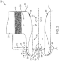
FIG. 2 is a schematic view of another embodiment of a particle separation system; and -
FIG. 3 is a schematic view of another embodiment of a particle separation system. - Referring to
FIG. 1 aparticle separation system 100 is shown. In the illustrated embodiment, theparticle separation system 100 includes afan housing 102, aparticle passage 108, acircumferential volute 110, aduct 114, and a heat exchanger 150. Theparticle separation system 100 can be utilized to remove particles and debris from anexterior air flow 101 before theexterior air flow 101 flows through the heat exchanger 150. Advantageously, the use of theparticle separation system 100 can prevent heat exchanger 150 fouling and reduce or eliminate the need to clean the heat exchanger 150. - In the illustrated embodiment, the
fan housing 102 can be disposed on an aircraft body to receiveexterior air flow 101. Thefan housing 102 may guide theexterior air flow 101 into the contractingpassage 104 of theparticle separation system 100. In certain embodiments,struts 120 can provide structural support to thefan housing 102. - During ground and low speed operations,
exterior air flow 101 may be directed into the contractingpassage 104 to be accelerated by thefan 140. In the illustrated embodiment, theexterior air flow 101 can include dirt, debris, dust, particulate matter, etc. - In certain embodiments,
sprayers 130 can spray water or other suitable fluid upstream of thefan 140 to cool theexterior air flow 101. The sprayed water may be previously condensed by the environmental control system of the aircraft to reduce the temperature of theexterior air flow 101 by undergoing evaporation. In certain embodiments, thesprayers 130 can be disposed along the walls of the contractingpassage 104. In certain embodiments,sprayers 130 can be disposed upstream of the heat exchanger 150 to further depress air temperatures. In other embodiments, thesprayers 130 can be disposed in any suitable location. - In the illustrated embodiment, a
fan 140 can be utilized during ground and low aircraft speed operations to drawexterior air flow 101 into theparticle separation system 100 and to the heat exchanger 150. In the illustrated embodiment, thefan 140 is driven by a rotatingshaft 141 to rotate thefan blades 142. In certain embodiments, therotating shaft 141 may provide power to thefan 140 from the air cycle machine that comprises a portion of the overall environmental control system. Advantageously, the use of thesprayers 130 upstream of thefan 140 can reducefan 140 work to lower fan exhaust temperatures, allowing for greater cooling within the heat exchanger 150. In certain embodiments,lower fan 140 temperatures allows for the use of lightweight, inexpensive composite materials such as fiber-reinforced plastic forfan blades 142 as well as for other portions of thefan 140. Further, the use of the relatively straight contractingpassage 104 can increase uniformity of theexterior air flow 101, resulting ingreater fan 140 efficiency. - During operation, centrifugal force imparted by the
fan 140 causes particulate matter within theexterior air flow 101 to segregate toward the outer periphery of thefan blades 142. In the illustrated embodiment, theexterior air flow 101 is directed through the curvedair flow path 112. The curvedair flow path 112 includes aninner radius 113a and anouter radius 113b. In the illustrated embodiment, the particulate matter is directed toward theinner radius 113a of thecurved flow path 112. In certain embodiments, the curvedair flow path 112 can direct theexterior air flow 101 up to 180 degrees from the original flow direction, reversing the direction of theexterior air flow 101. - In the illustrated embodiment, particulate matter is captured in the
particle passage 108. In the illustrated embodiment, theparticle passage 108 is disposed along theinner radius 113a of the curvedair flow path 112 beyond thefan 140. In the illustrated embodiment, theparticle passage 108 can receive particulate matter since the mass of ingested foreign particles is considerably greater than that of the air being pumped causing inertial forces to force the particulate matter away from the air trajectory of theexterior air flow 101 through the curvedair flow path 112. - In the illustrated embodiment, particulate matter captured within the
particle passage 108 is directed into thecircumferential volute 110. From thecircumferential volute 110, particulate matter is directed to adownstream region 116 beyond the heat exchanger 150. In the illustrated embodiment, thedownstream region 116 is a lower pressure region facilitating the flow of particulate matter away from the curvedair flow path 112. Particulate matter is then eliminated overboard by theexterior air flow 101 beyond the heat exchanger 150. - In certain embodiments,
bypass valves 106 can be utilized to bypass thefan 140 and theair flow path 112 to allowexterior air flow 101 to directly interact with the heat exchanger 150. Thebypass valve 106 may be opened during flight when thefan 140 may be required to a lesser extent to direct air to the heat exchanger 150. - In the illustrated embodiment, the heat exchanger 150 is exposed to the
exterior air flow 101. The heat exchanger 150 can allow a fluid within the heat exchanger 150 to be cooled by theexterior air flow 101. Advantageously, theparticle separation system 100 allows for particulate matter to be separated and removed in adownstream region 116 of the heat exchanger 150, allowing for greater efficiency. - Referring to
FIG. 2 , aparticle separation system 200 is shown. In the illustrated embodiment, similar numerals represent similar elements as described inFIG. 1 . In the illustrated embodiment, theparticle separation system 200 further includes asplitter 262 disposed within the curvedair flow path 212 to define aninner channel 209 and anouter channel 208. - In the illustrated embodiment, during operation,
exterior air flow 201 undergoes significant acceleration within the curvedair flow path 212. In the illustrated embodiment, theinner channel 209 is disposed adjacent to theinner radius 213a. During operation, the accelerated air flow has a lower inertia allowing theexterior air flow 201 to be directed into theinner channel 209. - In the illustrated embodiment, the
outer channel 208 is disposed adjacent to theouter radius 213b. Particulate matter is forced toward theouter channel 208. Similarly, theouter channel 208 terminates with acircumferential volute 210, wherein particulate matter is transferred to adownstream region 216 as described inFIG. 1 . - Further, in the illustrated embodiment, the
fan 240 includes anair flow device 244. In the illustrated embodiment, theair flow device 244 is a spinning aerodynamic device to direct air flow and prevent undesired flow characteristics. In certain embodiments, theair flow device 244 includes an aerodynamically shaped fan hub and casing to provide a convergent flow path along the flow direction. - Referring to
FIG. 3 , aparticle separation system 300 is shown. In the illustrated embodiment, similar numerals represent similar elements as described inFIG. 1 . In the illustrated embodiment, theparticle separation system 300 utilizes anelectric fan 340. Advantageously, thefan body 302 and theflow path 312 can be designed without consideration of a mechanical shaft to drive the fan. Further, the use of anelectrical fan 340 upstream of theheat exchanger 350 allows for ease of motor cooling. Thefan 340 may be supported by fan struts 346. - The terminology used herein is for the purpose of describing particular embodiments only and is not intended to be limiting of the embodiments. While the description of the present embodiments has been presented for purposes of illustration and description, it is not intended to be exhaustive or limited to the embodiments in the form disclosed. Many modifications, variations, alterations, substitutions or equivalent arrangement not hereto described will be apparent to those of ordinary skill in the art without departing from the scope and spirit of the embodiments. Additionally, while various embodiments have been described, it is to be understood that aspects may include only some of the described embodiments. Accordingly, the embodiments are not to be seen as limited by the foregoing description, but are only limited by the scope of the appended claims.
Claims (15)
- A particle separation device to remove particulate matter from an exterior air flow for use with an environmental control system, the particle separation device comprising:a curved airflow path (112) with an inner radius (113a) and an outer radius (113b), the curved air flow path (112) to receive the exterior air flow;a particle passage (108) disposed along at least one of the inner radius (113a) and the outer radius (113b) to receive the particulate matter from the exterior air flow;a circumferential volute (110) to receive the particulate matter from the particle passage (108); anda duct (114) to transport the particulate matter from the circumferential volute to a downstream region.
- The particle separation device of claim 1, wherein the curved airflow path (112) redirects the exterior air flow approximately 180 degrees.
- The particle separation device of claim 1 or 2, wherein the curved airflow path (112) includes a splitter (262) defining an inner channel adjacent to the inner radius of the curved air flow path (112) and an outer channel adjacent to the outer radius.
- The particle separation device of any preceding claim, wherein the particle separation device is disposed upstream of a heat exchanger (150) and downstream of a fan and the downstream region is downstream of the heat exchanger (150).
- The particle separation device of any preceding claim, further comprising a bypass valve (106) to direct the exterior air flow beyond the curved air flow path (112).
- The particle separation device of any preceding claim, further comprising a contracting passage (104) to direct the exterior air flow to the curved air flow path (112).
- The particle separation device of any preceding claim, further comprising at least one sprayer to spray a liquid into the exterior air flow.
- A particle separation system to remove particulate matter from an exterior air flow for use with an environmental control system, the particle separation system comprising:a fan (140) to accelerate the exterior air flow;a curved airflow path (112) with an inner radius (113a) and an outer radius (113b), the curved air flow path (112) to receive the exterior air flow;a heat exchanger (150) to receive the exterior air flow from the curved air flow path;a particle passage (108) disposed along at least one of the inner radius and the outer radius to receive the particulate matter from the exterior air flow;a circumferential volute (110) to receive the particulate matter from the particle passage; anda duct (114) to transport the particulate matter from the circumferential volute to a downstream region disposed downstream of the heat exchanger.
- The particle separation system of claim 8, wherein the curved airflow path (112) redirects the exterior air flow approximately 180 degrees.
- The particle separation system of claim 8 or 9, wherein the curved airflow path (112) includes a splitter (262) defining an inner channel adjacent to the inner radius of the curved air flow path and an outer channel adjacent to the outer radius.
- The particle separation system of claim 8, 9 or 10, further comprising a bypass valve (106) to direct the exterior air flow beyond the curved air flow path.
- The particle separation system of any of claims 8 to 11, further comprising a contracting passage (104) to direct the exterior air flow to the curved air flow path (112).
- The particle separation system of any of claims 8 to 12, further comprising at least one sprayer (262) to spray a liquid into the exterior air flow, wherein the at least one sprayer (262) is disposed upstream of the fan and the heat exchanger (150).
- The particle separation system of any of claims 8 to 13, wherein the fan (140) is a shaft powered fan and includes a flow device to direct the exterior air flow.
- The particle separation system of any of claims 8 to 14, wherein the fan (140) is an electric fan.
Applications Claiming Priority (1)
| Application Number | Priority Date | Filing Date | Title |
|---|---|---|---|
| US15/176,970 US10369503B2 (en) | 2016-06-08 | 2016-06-08 | Particle separation system |
Publications (2)
| Publication Number | Publication Date |
|---|---|
| EP3254744A1 true EP3254744A1 (en) | 2017-12-13 |
| EP3254744B1 EP3254744B1 (en) | 2025-04-09 |
Family
ID=59030875
Family Applications (1)
| Application Number | Title | Priority Date | Filing Date |
|---|---|---|---|
| EP17174976.5A Active EP3254744B1 (en) | 2016-06-08 | 2017-06-08 | Particle separation system |
Country Status (2)
| Country | Link |
|---|---|
| US (1) | US10369503B2 (en) |
| EP (1) | EP3254744B1 (en) |
Cited By (1)
| Publication number | Priority date | Publication date | Assignee | Title |
|---|---|---|---|---|
| CN113798182A (en) * | 2021-08-03 | 2021-12-17 | 唐山黑猫炭黑有限责任公司 | Carbon black separation and impurity removal method and device |
Families Citing this family (3)
| Publication number | Priority date | Publication date | Assignee | Title |
|---|---|---|---|---|
| TWI666047B (en) * | 2018-03-09 | 2019-07-21 | 緯穎科技服務股份有限公司 | Dust collector and electronic system capable of automatically removing dust |
| WO2019231398A1 (en) * | 2018-06-01 | 2019-12-05 | Mobiair Pte. Ltd. | Apparatus and method to clean particle loaded fluid using low energy multi flow-splitter technology requiring no filter media |
| CN112121576B (en) * | 2020-09-17 | 2021-11-23 | 成都精准混凝土有限公司 | Dust removal device for concrete mixing plant |
Citations (4)
| Publication number | Priority date | Publication date | Assignee | Title |
|---|---|---|---|---|
| US4292050A (en) * | 1979-11-15 | 1981-09-29 | Linhardt & Associates, Inc. | Curved duct separator for removing particulate matter from a carrier gas |
| US5261242A (en) * | 1990-12-07 | 1993-11-16 | Lardinois Jean Paul | Process for extraction of a substance from a gaseous carrier gas, as solid or liquid particles and system to operate the process |
| EP2584168A2 (en) * | 2011-10-21 | 2013-04-24 | United Technologies Corporation | Integrated thermal system for a gas turbine engine |
| WO2016032585A2 (en) * | 2014-05-29 | 2016-03-03 | General Electric Company | Turbine engine, components, and methods of cooling same |
Family Cites Families (18)
| Publication number | Priority date | Publication date | Assignee | Title |
|---|---|---|---|---|
| US2047568A (en) * | 1935-07-08 | 1936-07-14 | Int Precipitation Co | Method and apparatus for separating suspended particles from gases |
| US2221385A (en) * | 1938-11-05 | 1940-11-12 | Riley Stoker Corp | Separation of solids from gases |
| US2468607A (en) * | 1946-01-11 | 1949-04-26 | Claude B Schneible | Collecting and separating apparatus |
| NL261844A (en) * | 1960-03-25 | |||
| US3320729A (en) * | 1963-05-17 | 1967-05-23 | Westinghouse Electric Corp | Apparatus for removing liquid from a liquid laden gas stream |
| US3509932A (en) * | 1967-11-16 | 1970-05-05 | John Chambers | Forced convection surface evaporator |
| US3710561A (en) * | 1969-12-24 | 1973-01-16 | Amf Inc | Apparatus for separating solid particles suspended in a gaseous stream |
| US4111671A (en) * | 1975-06-19 | 1978-09-05 | Chemetron Corporation | Method and apparatus for carbon dioxide snow separation |
| US4179273A (en) | 1978-10-27 | 1979-12-18 | Grumman Aerospace Corporation | Dual scavenging separator |
| US4456458A (en) * | 1982-09-20 | 1984-06-26 | The De Havilland Aircraft Of Canada, Limited | Air intake system for engine |
| US10286407B2 (en) | 2007-11-29 | 2019-05-14 | General Electric Company | Inertial separator |
| US7927408B2 (en) * | 2007-11-30 | 2011-04-19 | Honeywell International Inc. | Inlet particle separator systems and methods |
| EP2310109A4 (en) * | 2008-07-14 | 2012-03-28 | Tenoroc Llc | Aerodynamic separation nozzle |
| US9314723B2 (en) * | 2012-09-17 | 2016-04-19 | Honeywell International Inc. | Inlet particle separator systems and methods |
| US20140144123A1 (en) * | 2012-11-29 | 2014-05-29 | Honeywell International Inc. | Inlet particle separator system with air injection |
| US9027202B2 (en) * | 2013-03-08 | 2015-05-12 | Federal Signal Corporation | Low pressure drop dust collectors |
| US9199248B2 (en) | 2013-10-01 | 2015-12-01 | Honeywell International Inc. | Aircraft electronic particle separation system |
| US9862495B2 (en) | 2013-12-18 | 2018-01-09 | Hamilton Sundstrand Corporation | Aircraft air-conditioning heat exchanger contamination detection |
-
2016
- 2016-06-08 US US15/176,970 patent/US10369503B2/en active Active
-
2017
- 2017-06-08 EP EP17174976.5A patent/EP3254744B1/en active Active
Patent Citations (4)
| Publication number | Priority date | Publication date | Assignee | Title |
|---|---|---|---|---|
| US4292050A (en) * | 1979-11-15 | 1981-09-29 | Linhardt & Associates, Inc. | Curved duct separator for removing particulate matter from a carrier gas |
| US5261242A (en) * | 1990-12-07 | 1993-11-16 | Lardinois Jean Paul | Process for extraction of a substance from a gaseous carrier gas, as solid or liquid particles and system to operate the process |
| EP2584168A2 (en) * | 2011-10-21 | 2013-04-24 | United Technologies Corporation | Integrated thermal system for a gas turbine engine |
| WO2016032585A2 (en) * | 2014-05-29 | 2016-03-03 | General Electric Company | Turbine engine, components, and methods of cooling same |
Cited By (2)
| Publication number | Priority date | Publication date | Assignee | Title |
|---|---|---|---|---|
| CN113798182A (en) * | 2021-08-03 | 2021-12-17 | 唐山黑猫炭黑有限责任公司 | Carbon black separation and impurity removal method and device |
| CN113798182B (en) * | 2021-08-03 | 2023-07-14 | 唐山黑猫炭黑有限责任公司 | Carbon black separation impurity removal method and device |
Also Published As
| Publication number | Publication date |
|---|---|
| US20170354908A1 (en) | 2017-12-14 |
| US10369503B2 (en) | 2019-08-06 |
| EP3254744B1 (en) | 2025-04-09 |
Similar Documents
| Publication | Publication Date | Title |
|---|---|---|
| EP3254744B1 (en) | Particle separation system | |
| US6134874A (en) | Integral inertial particle separator for radial inlet gas turbine engine | |
| EP2617648B1 (en) | Shrouded particle seperator | |
| US20190135441A1 (en) | Regenerative system ecoecs | |
| EP3427812B1 (en) | Water extractor for environmental control system of an aircraft | |
| JP6205107B2 (en) | Inlet particle separation system | |
| EP3412354B1 (en) | Tangential entry water separator for aircraft ecs | |
| EP3073121A1 (en) | Bearing cooling flow and energy recovery systems | |
| EP3473547A1 (en) | Integrated heat management for hybrid propulsion | |
| US9989070B2 (en) | Air cycle machine strut plate assembly | |
| JP6010348B2 (en) | Axial flow compressor and gas turbine provided with the same | |
| JP2001500943A (en) | Steam turbine, steam turbine equipment, and cooling method for steam turbine | |
| CN105715380A (en) | System And Method With Inlet Particle Separator | |
| EP3677508A1 (en) | Concentric turbine condensing cycle | |
| US9759236B2 (en) | Inlet tube design | |
| US2969908A (en) | Impulse axial-flow compressor | |
| EP2995780B1 (en) | Rotary machine air deflector | |
| GB2634476A (en) | Disc brake assembly particulate collection system | |
| EP4431396B1 (en) | Air-conducting structure for an aircraft, air ejector or ejector pump, and aircraft | |
| US12152495B1 (en) | Turbine with a plurality of inlet nozzles | |
| CN108119416B (en) | Bladeless cooling fan and engine system | |
| US20240410432A1 (en) | Disc brake assembly particulate collection system | |
| EP3061947B1 (en) | Fluid intake having particle separators | |
| CN112049823B (en) | Hoop fan cooling system of turbofan engine | |
| WO2013189995A1 (en) | An air handling system |
Legal Events
| Date | Code | Title | Description |
|---|---|---|---|
| PUAI | Public reference made under article 153(3) epc to a published international application that has entered the european phase |
Free format text: ORIGINAL CODE: 0009012 |
|
| STAA | Information on the status of an ep patent application or granted ep patent |
Free format text: STATUS: THE APPLICATION HAS BEEN PUBLISHED |
|
| AK | Designated contracting states |
Kind code of ref document: A1 Designated state(s): AL AT BE BG CH CY CZ DE DK EE ES FI FR GB GR HR HU IE IS IT LI LT LU LV MC MK MT NL NO PL PT RO RS SE SI SK SM TR |
|
| AX | Request for extension of the european patent |
Extension state: BA ME |
|
| STAA | Information on the status of an ep patent application or granted ep patent |
Free format text: STATUS: REQUEST FOR EXAMINATION WAS MADE |
|
| 17P | Request for examination filed |
Effective date: 20180613 |
|
| RBV | Designated contracting states (corrected) |
Designated state(s): AL AT BE BG CH CY CZ DE DK EE ES FI FR GB GR HR HU IE IS IT LI LT LU LV MC MK MT NL NO PL PT RO RS SE SI SK SM TR |
|
| STAA | Information on the status of an ep patent application or granted ep patent |
Free format text: STATUS: EXAMINATION IS IN PROGRESS |
|
| 17Q | First examination report despatched |
Effective date: 20191218 |
|
| REG | Reference to a national code |
Ref country code: DE Ref legal event code: R079 Free format text: PREVIOUS MAIN CLASS: B01D0045160000 Ref country code: DE Ref legal event code: R079 Ref document number: 602017088784 Country of ref document: DE Free format text: PREVIOUS MAIN CLASS: B01D0045160000 Ipc: B64D0013060000 |
|
| GRAP | Despatch of communication of intention to grant a patent |
Free format text: ORIGINAL CODE: EPIDOSNIGR1 |
|
| STAA | Information on the status of an ep patent application or granted ep patent |
Free format text: STATUS: GRANT OF PATENT IS INTENDED |
|
| RIC1 | Information provided on ipc code assigned before grant |
Ipc: B01D 45/16 20060101ALI20241022BHEP Ipc: B64D 13/06 20060101AFI20241022BHEP |
|
| INTG | Intention to grant announced |
Effective date: 20241111 |
|
| RAP3 | Party data changed (applicant data changed or rights of an application transferred) |
Owner name: HAMILTON SUNDSTRAND CORPORATION |
|
| GRAS | Grant fee paid |
Free format text: ORIGINAL CODE: EPIDOSNIGR3 |
|
| GRAA | (expected) grant |
Free format text: ORIGINAL CODE: 0009210 |
|
| STAA | Information on the status of an ep patent application or granted ep patent |
Free format text: STATUS: THE PATENT HAS BEEN GRANTED |
|
| AK | Designated contracting states |
Kind code of ref document: B1 Designated state(s): AL AT BE BG CH CY CZ DE DK EE ES FI FR GB GR HR HU IE IS IT LI LT LU LV MC MK MT NL NO PL PT RO RS SE SI SK SM TR |
|
| REG | Reference to a national code |
Ref country code: GB Ref legal event code: FG4D |
|
| REG | Reference to a national code |
Ref country code: CH Ref legal event code: EP |
|
| REG | Reference to a national code |
Ref country code: DE Ref legal event code: R096 Ref document number: 602017088784 Country of ref document: DE |
|
| REG | Reference to a national code |
Ref country code: IE Ref legal event code: FG4D |
|
| REG | Reference to a national code |
Ref country code: NL Ref legal event code: MP Effective date: 20250409 |
|
| PG25 | Lapsed in a contracting state [announced via postgrant information from national office to epo] |
Ref country code: NL Free format text: LAPSE BECAUSE OF FAILURE TO SUBMIT A TRANSLATION OF THE DESCRIPTION OR TO PAY THE FEE WITHIN THE PRESCRIBED TIME-LIMIT Effective date: 20250409 |
|
| REG | Reference to a national code |
Ref country code: AT Ref legal event code: MK05 Ref document number: 1783347 Country of ref document: AT Kind code of ref document: T Effective date: 20250409 |
|
| PG25 | Lapsed in a contracting state [announced via postgrant information from national office to epo] |
Ref country code: ES Free format text: LAPSE BECAUSE OF FAILURE TO SUBMIT A TRANSLATION OF THE DESCRIPTION OR TO PAY THE FEE WITHIN THE PRESCRIBED TIME-LIMIT Effective date: 20250409 Ref country code: FI Free format text: LAPSE BECAUSE OF FAILURE TO SUBMIT A TRANSLATION OF THE DESCRIPTION OR TO PAY THE FEE WITHIN THE PRESCRIBED TIME-LIMIT Effective date: 20250409 Ref country code: PT Free format text: LAPSE BECAUSE OF FAILURE TO SUBMIT A TRANSLATION OF THE DESCRIPTION OR TO PAY THE FEE WITHIN THE PRESCRIBED TIME-LIMIT Effective date: 20250811 |
|
| REG | Reference to a national code |
Ref country code: LT Ref legal event code: MG9D |
|
| PG25 | Lapsed in a contracting state [announced via postgrant information from national office to epo] |
Ref country code: NO Free format text: LAPSE BECAUSE OF FAILURE TO SUBMIT A TRANSLATION OF THE DESCRIPTION OR TO PAY THE FEE WITHIN THE PRESCRIBED TIME-LIMIT Effective date: 20250709 Ref country code: GR Free format text: LAPSE BECAUSE OF FAILURE TO SUBMIT A TRANSLATION OF THE DESCRIPTION OR TO PAY THE FEE WITHIN THE PRESCRIBED TIME-LIMIT Effective date: 20250710 |
|
| PG25 | Lapsed in a contracting state [announced via postgrant information from national office to epo] |
Ref country code: PL Free format text: LAPSE BECAUSE OF FAILURE TO SUBMIT A TRANSLATION OF THE DESCRIPTION OR TO PAY THE FEE WITHIN THE PRESCRIBED TIME-LIMIT Effective date: 20250409 |
|
| PG25 | Lapsed in a contracting state [announced via postgrant information from national office to epo] |
Ref country code: BG Free format text: LAPSE BECAUSE OF FAILURE TO SUBMIT A TRANSLATION OF THE DESCRIPTION OR TO PAY THE FEE WITHIN THE PRESCRIBED TIME-LIMIT Effective date: 20250409 |
|
| PG25 | Lapsed in a contracting state [announced via postgrant information from national office to epo] |
Ref country code: HR Free format text: LAPSE BECAUSE OF FAILURE TO SUBMIT A TRANSLATION OF THE DESCRIPTION OR TO PAY THE FEE WITHIN THE PRESCRIBED TIME-LIMIT Effective date: 20250409 |
|
| PG25 | Lapsed in a contracting state [announced via postgrant information from national office to epo] |
Ref country code: AT Free format text: LAPSE BECAUSE OF FAILURE TO SUBMIT A TRANSLATION OF THE DESCRIPTION OR TO PAY THE FEE WITHIN THE PRESCRIBED TIME-LIMIT Effective date: 20250409 |
|
| PG25 | Lapsed in a contracting state [announced via postgrant information from national office to epo] |
Ref country code: RS Free format text: LAPSE BECAUSE OF FAILURE TO SUBMIT A TRANSLATION OF THE DESCRIPTION OR TO PAY THE FEE WITHIN THE PRESCRIBED TIME-LIMIT Effective date: 20250709 |
|
| PG25 | Lapsed in a contracting state [announced via postgrant information from national office to epo] |
Ref country code: IS Free format text: LAPSE BECAUSE OF FAILURE TO SUBMIT A TRANSLATION OF THE DESCRIPTION OR TO PAY THE FEE WITHIN THE PRESCRIBED TIME-LIMIT Effective date: 20250809 |
|
| PG25 | Lapsed in a contracting state [announced via postgrant information from national office to epo] |
Ref country code: LV Free format text: LAPSE BECAUSE OF FAILURE TO SUBMIT A TRANSLATION OF THE DESCRIPTION OR TO PAY THE FEE WITHIN THE PRESCRIBED TIME-LIMIT Effective date: 20250409 |
|
| REG | Reference to a national code |
Ref country code: DE Ref legal event code: R119 Ref document number: 602017088784 Country of ref document: DE |
|
| PG25 | Lapsed in a contracting state [announced via postgrant information from national office to epo] |
Ref country code: DK Free format text: LAPSE BECAUSE OF FAILURE TO SUBMIT A TRANSLATION OF THE DESCRIPTION OR TO PAY THE FEE WITHIN THE PRESCRIBED TIME-LIMIT Effective date: 20250409 Ref country code: SM Free format text: LAPSE BECAUSE OF FAILURE TO SUBMIT A TRANSLATION OF THE DESCRIPTION OR TO PAY THE FEE WITHIN THE PRESCRIBED TIME-LIMIT Effective date: 20250409 |
|
| PG25 | Lapsed in a contracting state [announced via postgrant information from national office to epo] |
Ref country code: CZ Free format text: LAPSE BECAUSE OF FAILURE TO SUBMIT A TRANSLATION OF THE DESCRIPTION OR TO PAY THE FEE WITHIN THE PRESCRIBED TIME-LIMIT Effective date: 20250409 |
|
| PG25 | Lapsed in a contracting state [announced via postgrant information from national office to epo] |
Ref country code: EE Free format text: LAPSE BECAUSE OF FAILURE TO SUBMIT A TRANSLATION OF THE DESCRIPTION OR TO PAY THE FEE WITHIN THE PRESCRIBED TIME-LIMIT Effective date: 20250409 |
|
| PG25 | Lapsed in a contracting state [announced via postgrant information from national office to epo] |
Ref country code: SK Free format text: LAPSE BECAUSE OF FAILURE TO SUBMIT A TRANSLATION OF THE DESCRIPTION OR TO PAY THE FEE WITHIN THE PRESCRIBED TIME-LIMIT Effective date: 20250409 Ref country code: RO Free format text: LAPSE BECAUSE OF FAILURE TO SUBMIT A TRANSLATION OF THE DESCRIPTION OR TO PAY THE FEE WITHIN THE PRESCRIBED TIME-LIMIT Effective date: 20250409 |
|
| REG | Reference to a national code |
Ref country code: CH Ref legal event code: H13 Free format text: ST27 STATUS EVENT CODE: U-0-0-H10-H13 (AS PROVIDED BY THE NATIONAL OFFICE) Effective date: 20260127 |
|
| PG25 | Lapsed in a contracting state [announced via postgrant information from national office to epo] |
Ref country code: IT Free format text: LAPSE BECAUSE OF FAILURE TO SUBMIT A TRANSLATION OF THE DESCRIPTION OR TO PAY THE FEE WITHIN THE PRESCRIBED TIME-LIMIT Effective date: 20250409 |
|
| PG25 | Lapsed in a contracting state [announced via postgrant information from national office to epo] |
Ref country code: MC Free format text: LAPSE BECAUSE OF FAILURE TO SUBMIT A TRANSLATION OF THE DESCRIPTION OR TO PAY THE FEE WITHIN THE PRESCRIBED TIME-LIMIT Effective date: 20250409 |
|
| PLBE | No opposition filed within time limit |
Free format text: ORIGINAL CODE: 0009261 |
|
| STAA | Information on the status of an ep patent application or granted ep patent |
Free format text: STATUS: NO OPPOSITION FILED WITHIN TIME LIMIT |
|
| PG25 | Lapsed in a contracting state [announced via postgrant information from national office to epo] |
Ref country code: LU Free format text: LAPSE BECAUSE OF NON-PAYMENT OF DUE FEES Effective date: 20250608 |
|
| REG | Reference to a national code |
Ref country code: CH Ref legal event code: L10 Free format text: ST27 STATUS EVENT CODE: U-0-0-L10-L00 (AS PROVIDED BY THE NATIONAL OFFICE) Effective date: 20260218 |
|
| REG | Reference to a national code |
Ref country code: BE Ref legal event code: MM Effective date: 20250630 |
|
| 26N | No opposition filed |
Effective date: 20260112 |
|
| PG25 | Lapsed in a contracting state [announced via postgrant information from national office to epo] |
Ref country code: IE Free format text: LAPSE BECAUSE OF NON-PAYMENT OF DUE FEES Effective date: 20250608 Ref country code: DE Free format text: LAPSE BECAUSE OF NON-PAYMENT OF DUE FEES Effective date: 20260101 |
|
| PG25 | Lapsed in a contracting state [announced via postgrant information from national office to epo] |
Ref country code: BE Free format text: LAPSE BECAUSE OF NON-PAYMENT OF DUE FEES Effective date: 20250630 |
|
| PG25 | Lapsed in a contracting state [announced via postgrant information from national office to epo] |
Ref country code: CH Free format text: LAPSE BECAUSE OF NON-PAYMENT OF DUE FEES Effective date: 20250630 |
|
| PG25 | Lapsed in a contracting state [announced via postgrant information from national office to epo] |
Ref country code: LT Free format text: LAPSE BECAUSE OF FAILURE TO SUBMIT A TRANSLATION OF THE DESCRIPTION OR TO PAY THE FEE WITHIN THE PRESCRIBED TIME-LIMIT Effective date: 20250409 |
|
| PGFP | Annual fee paid to national office [announced via postgrant information from national office to epo] |
Ref country code: GB Payment date: 20260520 Year of fee payment: 10 |
|
| PGFP | Annual fee paid to national office [announced via postgrant information from national office to epo] |
Ref country code: FR Payment date: 20260520 Year of fee payment: 10 |
|
| PG25 | Lapsed in a contracting state [announced via postgrant information from national office to epo] |
Ref country code: CY Free format text: LAPSE BECAUSE OF FAILURE TO SUBMIT A TRANSLATION OF THE DESCRIPTION OR TO PAY THE FEE WITHIN THE PRESCRIBED TIME-LIMIT Effective date: 20250409 Ref country code: SE Free format text: LAPSE BECAUSE OF FAILURE TO SUBMIT A TRANSLATION OF THE DESCRIPTION OR TO PAY THE FEE WITHIN THE PRESCRIBED TIME-LIMIT Effective date: 20250409 |