EP3254738A1 - Manipulating device - Google Patents
Manipulating device Download PDFInfo
- Publication number
- EP3254738A1 EP3254738A1 EP17174003.8A EP17174003A EP3254738A1 EP 3254738 A1 EP3254738 A1 EP 3254738A1 EP 17174003 A EP17174003 A EP 17174003A EP 3254738 A1 EP3254738 A1 EP 3254738A1
- Authority
- EP
- European Patent Office
- Prior art keywords
- manipulating
- analog manipulator
- buttons
- manipulator
- analog
- Prior art date
- Legal status (The legal status is an assumption and is not a legal conclusion. Google has not performed a legal analysis and makes no representation as to the accuracy of the status listed.)
- Withdrawn
Links
Images





Classifications
-
- A—HUMAN NECESSITIES
- A63—SPORTS; GAMES; AMUSEMENTS
- A63F—CARD, BOARD, OR ROULETTE GAMES; INDOOR GAMES USING SMALL MOVING PLAYING BODIES; VIDEO GAMES; GAMES NOT OTHERWISE PROVIDED FOR
- A63F13/00—Video games, i.e. games using an electronically generated display having two or more dimensions
- A63F13/20—Input arrangements for video game devices
- A63F13/24—Constructional details thereof, e.g. game controllers with detachable joystick handles
- A63F13/245—Constructional details thereof, e.g. game controllers with detachable joystick handles specially adapted to a particular type of game, e.g. steering wheels
-
- A—HUMAN NECESSITIES
- A63—SPORTS; GAMES; AMUSEMENTS
- A63F—CARD, BOARD, OR ROULETTE GAMES; INDOOR GAMES USING SMALL MOVING PLAYING BODIES; VIDEO GAMES; GAMES NOT OTHERWISE PROVIDED FOR
- A63F13/00—Video games, i.e. games using an electronically generated display having two or more dimensions
- A63F13/20—Input arrangements for video game devices
- A63F13/24—Constructional details thereof, e.g. game controllers with detachable joystick handles
-
- A—HUMAN NECESSITIES
- A63—SPORTS; GAMES; AMUSEMENTS
- A63F—CARD, BOARD, OR ROULETTE GAMES; INDOOR GAMES USING SMALL MOVING PLAYING BODIES; VIDEO GAMES; GAMES NOT OTHERWISE PROVIDED FOR
- A63F13/00—Video games, i.e. games using an electronically generated display having two or more dimensions
- A63F13/20—Input arrangements for video game devices
- A63F13/21—Input arrangements for video game devices characterised by their sensors, purposes or types
- A63F13/211—Input arrangements for video game devices characterised by their sensors, purposes or types using inertial sensors, e.g. accelerometers or gyroscopes
-
- A—HUMAN NECESSITIES
- A63—SPORTS; GAMES; AMUSEMENTS
- A63F—CARD, BOARD, OR ROULETTE GAMES; INDOOR GAMES USING SMALL MOVING PLAYING BODIES; VIDEO GAMES; GAMES NOT OTHERWISE PROVIDED FOR
- A63F13/00—Video games, i.e. games using an electronically generated display having two or more dimensions
- A63F13/20—Input arrangements for video game devices
- A63F13/21—Input arrangements for video game devices characterised by their sensors, purposes or types
- A63F13/213—Input arrangements for video game devices characterised by their sensors, purposes or types comprising photodetecting means, e.g. cameras, photodiodes or infrared cells
-
- A—HUMAN NECESSITIES
- A63—SPORTS; GAMES; AMUSEMENTS
- A63F—CARD, BOARD, OR ROULETTE GAMES; INDOOR GAMES USING SMALL MOVING PLAYING BODIES; VIDEO GAMES; GAMES NOT OTHERWISE PROVIDED FOR
- A63F13/00—Video games, i.e. games using an electronically generated display having two or more dimensions
- A63F13/80—Special adaptations for executing a specific game genre or game mode
- A63F13/837—Shooting of targets
-
- A—HUMAN NECESSITIES
- A63—SPORTS; GAMES; AMUSEMENTS
- A63F—CARD, BOARD, OR ROULETTE GAMES; INDOOR GAMES USING SMALL MOVING PLAYING BODIES; VIDEO GAMES; GAMES NOT OTHERWISE PROVIDED FOR
- A63F13/00—Video games, i.e. games using an electronically generated display having two or more dimensions
- A63F13/90—Constructional details or arrangements of video game devices not provided for in groups A63F13/20 or A63F13/25, e.g. housing, wiring, connections or cabinets
- A63F13/98—Accessories, i.e. detachable arrangements optional for the use of the video game device, e.g. grip supports of game controllers
-
- G—PHYSICS
- G06—COMPUTING OR CALCULATING; COUNTING
- G06F—ELECTRIC DIGITAL DATA PROCESSING
- G06F3/00—Input arrangements for transferring data to be processed into a form capable of being handled by the computer; Output arrangements for transferring data from processing unit to output unit, e.g. interface arrangements
- G06F3/01—Input arrangements or combined input and output arrangements for interaction between user and computer
- G06F3/011—Arrangements for interaction with the human body, e.g. for user immersion in virtual reality
-
- G—PHYSICS
- G06—COMPUTING OR CALCULATING; COUNTING
- G06F—ELECTRIC DIGITAL DATA PROCESSING
- G06F3/00—Input arrangements for transferring data to be processed into a form capable of being handled by the computer; Output arrangements for transferring data from processing unit to output unit, e.g. interface arrangements
- G06F3/01—Input arrangements or combined input and output arrangements for interaction between user and computer
- G06F3/02—Input arrangements using manually operated switches, e.g. using keyboards or dials
-
- G—PHYSICS
- G06—COMPUTING OR CALCULATING; COUNTING
- G06F—ELECTRIC DIGITAL DATA PROCESSING
- G06F3/00—Input arrangements for transferring data to be processed into a form capable of being handled by the computer; Output arrangements for transferring data from processing unit to output unit, e.g. interface arrangements
- G06F3/01—Input arrangements or combined input and output arrangements for interaction between user and computer
- G06F3/03—Arrangements for converting the position or the displacement of a member into a coded form
- G06F3/0304—Detection arrangements using opto-electronic means
- G06F3/0308—Detection arrangements using opto-electronic means comprising a plurality of distinctive and separately oriented light emitters or reflectors associated to the pointing device, e.g. remote cursor controller with distinct and separately oriented LEDs at the tip whose radiations are captured by a photo-detector associated to the screen
-
- G—PHYSICS
- G06—COMPUTING OR CALCULATING; COUNTING
- G06F—ELECTRIC DIGITAL DATA PROCESSING
- G06F3/00—Input arrangements for transferring data to be processed into a form capable of being handled by the computer; Output arrangements for transferring data from processing unit to output unit, e.g. interface arrangements
- G06F3/01—Input arrangements or combined input and output arrangements for interaction between user and computer
- G06F3/03—Arrangements for converting the position or the displacement of a member into a coded form
- G06F3/033—Pointing devices displaced or positioned by the user, e.g. mice, trackballs, pens or joysticks; Accessories therefor
- G06F3/0338—Pointing devices displaced or positioned by the user, e.g. mice, trackballs, pens or joysticks; Accessories therefor with detection of limited linear or angular displacement of an operating part of the device from a neutral position, e.g. isotonic or isometric joysticks
-
- A—HUMAN NECESSITIES
- A63—SPORTS; GAMES; AMUSEMENTS
- A63F—CARD, BOARD, OR ROULETTE GAMES; INDOOR GAMES USING SMALL MOVING PLAYING BODIES; VIDEO GAMES; GAMES NOT OTHERWISE PROVIDED FOR
- A63F2300/00—Features of games using an electronically generated display having two or more dimensions, e.g. on a television screen, showing representations related to the game
- A63F2300/80—Features of games using an electronically generated display having two or more dimensions, e.g. on a television screen, showing representations related to the game specially adapted for executing a specific type of game
- A63F2300/8076—Shooting
Definitions
- the present disclosure relates to a manipulating device.
- Some manipulating devices for manipulating game machines and radio-controlled machines such as toy cars, toy boats, and small-size drones, for example, have an analog manipulator that can be tilted or slid in radial directions and a plurality of buttons.
- U.S. Patent Application Publication No. 2014/0102869 discloses a manipulating device having two analog manipulators. The disclosed manipulating device also has four buttons positioned at respective four ends of a crisscross pattern, i.e., a directional keypad, provided forwardly of the right analog manipulator, and another directional keypad provided forwardly of the left analog manipulator.
- a manipulating device including an analog manipulator tiltable or slidable in a second direction perpendicular to a central line along a first direction, and a plurality of manipulating buttons disposed in surrounding relation to the analog manipulator.
- the manipulating buttons include a first manipulating button positioned off the central line in the second direction, and when the analog manipulator is tilted or slid in the second direction, a position of an upper end of the first manipulating button along the first direction is higher than a position of an outer edge of the analog manipulator which is closer to the first manipulating button, along the first direction.
- the manipulating device thus constructed allows the analog manipulator and the manipulating buttons to be actuated smoothly in succession, i.e. one after another.
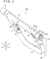
- FIG. 1 shows in perspective a manipulating device 100 according to the embodiment of the present disclosure.
- FIG. 2 shows the manipulating device 100 in side elevation.
- directions Y1 and Y2 shown in FIG. 1 will be referred to as forward and rearward directions, respectively, directions Z1 and Z2 as upward and downward directions, respectively, and directions X1 and X2 as rightward and leftward directions, respectively.
- the manipulating device 100 includes grips 11 and 12 to be gripped by the user.
- the manipulating device 100 according to the illustrated embodiment includes a rear grip 12 and a front grip 11 spaced forwardly from the rear grip 12.
- the manipulating device 100 also includes a rod-shaped upper elongate member 13 extending along the forward and rearward directions.
- the upper elongate member 13 is connected to the upper ends of the front and rear grips 11 and 12.
- the front grip 11 is connected to the front end of the upper elongate member 13, whereas the rear grip 12 is connected to the rear end of the upper elongate member 13.
- the front grip 11 extends downwardly from the upper elongate member 13 and obliquely rearwardly.
- the rear grip 12 extends downwardly from the rear end of the upper elongate member 13 and obliquely rearwardly.
- the front grip 11 is inclined at a greater gradient than the rear grip 12 such that the distance between the front grip 11 and the rear grip 12 is progressively smaller along the downward direction.
- the manipulating device 100 further includes a lower elongate member 14 interconnecting the lower end of the front grip 11 and the lower end of the rear grip 12.
- the manipulating device 100 serves as a game controller that is used to manipulate a game machine.
- the user grips the front grip 11 with one hand and grips the rear grip 12 with the other hand, and orients the front end of the elongate member 13 in the forward direction.
- the manipulating device 100 which is a controller that simulates a gun, includes a trigger 21 as shown in FIG. 2 .
- the trigger 21 is positioned between the uppermost portion of the rear grip 12 and the rearmost portion of the upper elongate member 13. The user can place a finger on the trigger 21 while gripping the rear grip 12.
- the manipulating device 100 is not limited to the configuration shown in FIGS. 1 and 2 , but may be modified in various ways.
- the manipulating device 100 may have one grip.
- the manipulating device 100 may not include the lower elongate member 14.
- the lower end of the front grip 11 may be separate from the lower end of the rear grip 12.
- the lower end of the front grip 11 may be directly connected to the lower end of the rear grip 12, so that the manipulating device 100 may be of a triangular shape as a whole.
- the manipulating device 100 includes an analog manipulator 30.
- the analog manipulator 30 can be tilted or slid along directions perpendicular to a central line C1, i.e., in radial directions of the analog manipulator 30.
- the central line C1 represents the central axis of a manipulator and button assembly.
- a signal is generated and output from a support mechanism 31 through a circuit board 33 to be described later.
- FIG. 3 shows in exploded perspective the analog manipulator 30, manipulating buttons 41A to 41D, and other members on the manipulating device 100.
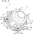
- FIG. 4 shows in enlarged perspective the circuit board 33 and members mounted thereon around the analog manipulator 30 shown in FIG. 3 .
- FIG. 5 shows the manipulating device 100 in cross section taken along line V-V of FIG. 1 .
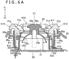
- FIGS. 6A and 6B show the analog manipulator 30 in cross section.
- the analog manipulator 30 is shown as being positioned in alignment with the central line C1, i.e., in its initial position.
- FIG. 6B the analog manipulator 30 is shown as being tilted in a radial direction from the central line C1.
- directions D1 and D2 shown in FIGS. 4 , 6A , and 6B i.e., directions along the central line C1 will be referred to as upward and downward directions, respectively.
- the analog manipulator 30 includes a disk-shaped upper portion 30a that can be touched by a user's finger and a post 30b extending from the upper portion 30a to the support mechanism 31 and supported by the support mechanism 31.
- the support mechanism 31 is mounted on the circuit board 33.
- the post 30b of the analog manipulator 30 has a lower end pivotally supported by the support mechanism 31 so that the analog manipulator 30 can be tilted in radial directions.
- the analog manipulator 30 is tiltable in any directions perpendicular to the central line C1, e.g., forward, rearward, rightward, and rearward directions.
- the support mechanism 31 may support the analog manipulator 30 in a manner to allow the analog manipulator 30 to slide in directions perpendicular to the central line C1.
- the analog manipulator 30 includes a cover 30c positioned below the upper portion 30a, i.e., on one side of the upper portion 30a which is closer to the support mechanism 31 and the circuit board 33.
- the analog manipulator 30 also includes a trunk 30d disposed contiguously beneath the upper portion 30a and smaller in diameter than the upper portion 30a.
- the cover 30c extends radially outwardly from the lower end of the trunk 30d and covers the support mechanism 31 as viewed in the direction of the central line C1.
- the manipulating device 100 includes a plurality of (four in the illustrated embodiment) manipulating buttons 41A, 41B, 41C, and 41D disposed in surrounding relation to the analog manipulator 30.
- This layout of the manipulating buttons 41A, 41B, 41C, and 41D allows the analog manipulator 30 and the manipulating buttons 41A, 41B, 41C, and 41D to be actuated smoothly in succession, i.e., one after another.
- the four manipulating buttons 41A, 41B, 41C, and 41D are disposed around the analog manipulator 30.
- Each of the four manipulating buttons 41A, 41B, 41C, and 41D may include a push button.
- manipulating buttons 41A, 41B, 41C, and 41D When the analog manipulator 30 is viewed along the central line C1, the four manipulating buttons 41 are positioned respectively on the upper, lower, right, and left sides of the analog manipulator 30.
- the number of manipulating buttons 41 is not limited to four, but may be three, two, or more than four, for example.
- an outer edge e1 of the analog manipulator 30 is brought closely to one of the manipulating buttons 41, i.e., the manipulating button 41 that is positioned in the direction along which the analog manipulator 30 is tilted.
- the manipulating buttons 41 are formed so as to project upwardly.
- the position of an upper end 41a of the manipulating button 41 along the central line C1 is higher than the outer edge of the analog manipulator 30 along the central line C1, i.e., the outer edge e1 in the direction along which the analog manipulator 30 is tilted.
- This positional relationship between the manipulating button 41 and the analog manipulator 30 is effective to prevent the analog manipulator 30 from presenting an obstacle to a user's finger action to actuate the manipulating button 41. Consequently, it is possible to allow the analog manipulator 30 and the manipulating button 41 to be actuated smoothly in succession.
- the positions of the upper ends 41a of plural of the manipulating buttons 41 along the central line C1 are higher than the outer edge of the analog manipulator 30 along the central line C1. More specifically, the position of the outer edge of the upper portion 30a of the analog manipulator 30 is lower than the positions of the upper ends 41a of the manipulating buttons 41.
- This positional relationship between the manipulating button 41 and the analog manipulator 30 is more effective to prevent the analog manipulator 30 from presenting an obstacle to a user's finger action to actuate the manipulating buttons 41.
- the upper portion 30a of the analog manipulator 30 When the analog manipulator 30 is in its initial position, as shown in FIG. 6A , the upper portion 30a of the analog manipulator 30 has an uppermost surface 30e positioned at the same height as the upper ends 41a of the manipulating buttons 41. Consequently, when the manipulating device 100 is not in use, for example, the manipulating buttons 41 prevent lateral external forces from acting on the upper portion 30a of the analog manipulator 30. Alternatively, the uppermost surface 30e of the upper portion 30a may be higher than or lower than the upper ends 41a of the manipulating buttons 41.
- the manipulating buttons 41 that surround the analog manipulator 30 are arranged in an annular pattern as a whole. With the manipulating buttons 41 being thus ring-shaped, either one of the manipulating buttons 41 is positioned at all times in any of the radial directions as viewed from the analog manipulator 30. Therefore, the user finds it easy to actuate any one of the manipulating buttons 41 in succession after actuating the analog manipulator 30.
- each of the manipulating buttons 41 is of an arcuate shape extending around the central line C1.
- the arcuate shape of the manipulating buttons 41 allows them to be long enough circumferentially around the central line C1. As a result, the user is able to press the manipulating buttons 41 smoothly and reliably.
- the ends of each of the manipulating buttons 41 along the circumferential directions are disposed in the vicinity of the ends of adjacent manipulating buttons 41. More specifically, the distance between the facing ends of adjacent two manipulating buttons 41 is smaller than the length of each of the manipulating buttons 41.
- Each of the manipulating buttons 41 is not limited to the arcuate shape according to the illustrated embodiment, but may be of a round shape. Each of the round manipulating buttons 41 may be spaced from adjacent manipulating buttons 41. The manipulating buttons 41 may be arranged in a quadrangular or triangular pattern as a whole. The manipulating buttons 41 in the illustrated embodiment have the same size. However, the manipulating buttons 41 may not necessarily be of the same size. Any of the manipulating buttons 41 which are considered to be used highly frequently may be longer than the other manipulating buttons 41 along the circumferential directions around the central line C1.
- the manipulating buttons 41 have respective inner peripheral surfaces 41e that jointly surround the upper portion 30a of the analog manipulator 30.
- the inner peripheral surfaces 41e include respective slanting surfaces 41f that extend progressively closer to the analog manipulator 30 along the downward direction from the upper ends 41a of the manipulating buttons 41 toward the circuit board 33.
- Each of the manipulating buttons 41 may have recess or projection surfaces on its portions bordering adjacent manipulating buttons 41. The user can easily distinguish two adjacent manipulating buttons 41 by feeling their recess or projection surfaces with a finger. As shown in FIG. 3 , the upper surface of each of the manipulating buttons 41 of the illustrated manipulating device 100 includes recess surfaces 41d on its end portions.
- the stop 35a of the manipulating device 100 serves to define the maximum displacement (maximum angle of tilt) of the analog manipulator 30.
- the stop 35a extends from a position beneath the lower edge of the inner peripheral surfaces 41e of the manipulating buttons 41 radially inwardly toward the analog manipulator 30.
- the stop 35a surrounds the analog manipulator 30 as it is viewed along the central line C1.
- the analog manipulator 30 can be tilted radially outwardly about the lower end of the post 30b that is pivotally supported by the support mechanism 31, until the trunk 30a abuts against the stop 35a.
- the upper portion 30a of the analog manipulator 30 stays clear of the inner peripheral surfaces 41e of the manipulating buttons 41.
- the manipulating device 100 includes the circuit board 33, and the support mechanism 31 is disposed on the circuit board 33.
- the circuit board 33 supports a plurality of switches 33a (see FIG. 4 ) installed thereon at respective positions below the manipulating buttons 41.
- the circuit board 33 supports thereon four switches 33a positioned in alignment with the respective manipulating buttons 41.
- the four switches 33a are positioned individually on the upper, lower, right, and left sides of the support mechanism 31.
- Each of the switches 33a includes a membrane switch, though it may be another switch such as a tact switch, for example.
- each of the manipulating buttons 41 has an upper portion 41g including the inner peripheral surface 41e and a lower portion 41i (see also FIG. 3 ) extending downwardly from the upper portion 41g. Downwardly from the lower end of the lower portion 41i, there projects a pusher 41h for pushing the corresponding switch 33a.
- the manipulating device 100 includes a plurality of springs 35b for returning the respective manipulating buttons 41 that have been pushed to their initial positions.
- Each of the springs 35b includes a leaf spring.
- the springs 35b and the stop 35a are integrally formed with each other. The number of parts that make up the manipulating device 100 is thus reduced.
- the springs 35b and the stop 35a may be made of resin.
- the manipulating device 100 includes an assembly 35 that includes the springs 35b and the stop 35a.
- the assembly 35 will hereinafter be referred to as "stop assembly 35."
- the stop assembly 35 includes a tube 35c extending downwardly from the outer circumferential edge of the stop 35a and surrounding the support mechanism 31.
- the springs 35b are formed on the lower edge of the tube 35c. Since the manipulating device 100 has the four manipulating buttons 41, the stop assembly 35 includes four springs 35b associated respectively with the four manipulating buttons 41.
- the springs 35b project radially outwardly from the lower edge of the tube 35c.
- the stop assembly 35 is fastened to the circuit board 33 by fasteners such as screws or the like.
- the stop assembly 35 includes a plurality of lugs 35g projecting from the lower edge of the tube 35c.
- the lugs 35g are fixed to the circuit board 33 by fasteners such as screws or the like.
- the springs 35b are positioned above the switches 33a.
- the pushers 41h ( FIG. 6A ) of the manipulating buttons 41 are positioned above the springs 35b.
- the pushers 41h push the switches 33a through the springs 35b.
- the stop assembly 35 is fastened to the circuit board 33 by fasteners such as screws or the like. Therefore, even if the switches 33a and the manipulating buttons 41 are positionally displaced out of alignment with each other, since the manipulating buttons 41 push the switches 33a through the springs 35b, the switches 33a are pushed at appropriate positions therefor by the pushers 41h through the springs 35b.
- each of the springs 35b includes two arms 35d projecting radially outwardly from the lower edge of the tube 35c, a joint 35e interconnecting the outer ends of the two arms 35d, and a rest 35f projecting from the joint 35e toward the tube 35c.
- the pusher 41h of one of the manipulating buttons 41 is positioned on the rest 35f, as shown in FIG. 6A .
- the pusher 41h thereof pushes the corresponding switch 33a through the rest 35f.
- the rest 35f has a recess defined in an upper surface thereof, and the pusher 41h has a lower end fitted in the recess.
- the rest 35f and the pusher 41h are thus held in alignment with each other against positional displacement.
- the springs 35b and the manipulating buttons 41 are not limited to the illustrated structures and shapes, but may be changed in structure and shape.
- the manipulating buttons 41 may be constructed such that they push the corresponding switches 33a directly.
- the manipulating device 100 includes a cover 45 serving as part of its outer casing and covering the circuit board 33.
- the manipulating buttons 41 are mounted on the cover 45.
- the cover 45 has a circular cavity 45a (see FIG. 3 ) defined therein in which the manipulating buttons 41 are disposed, and an inner circumferential ledge 45b projecting radially inwardly into the cavity 45a.
- the manipulating buttons 41 are supported on the inner circumferential ledge 45b.
- the inner circumferential ledge 45b has an attachment hole 45e defined therein in which the lower portions 41i of the manipulating buttons 41 are fitted.
- the cover 45 includes a wall 45g extending downwardly from an edge of the inner circumferential edge 45b which defines the attachment hole 45e.
- the lower portion 41i has pawls, not shown, on its lower end which engage the lower edge of the wall 45g, locking the manipulating buttons 41 in place against upward dislodgement off the cover 45.
- the tube 35c of the stop assembly 35 has a plurality of rib-shaped axial guides 35i on an outer circumferential surface thereof.
- the lower portions 41i of the manipulating buttons 41 are guided by the guides 35i to prevent the manipulating buttons 41 from being positionally displaced circumferentially around the central line C1.
- the analog manipulator 30 and the manipulating buttons 41 are disposed on the rear side of an uppermost portion of the rear grip 12.
- the analog manipulator 30 is arranged such that the central line C1 thereof is oriented rearwardly and upwardly (see FIG. 2 ).
- the trigger 21 is positioned on the front side of the uppermost portion of the rear grip 12.
- the analog manipulator 30 and the manipulating buttons 41 are positionally displaced upwardly from the trigger 21.
- the position of the center of the upper portion 30a of the analog manipulator 30 is higher than the position of the vertical center of the trigger 21.
- the positions of the analog manipulator 30 and the manipulating buttons 41 are set in a range accessible by the thumb while a finger, e.g., the index finger, is placed on the trigger 21.
- a finger e.g., the index finger
- the position of the center of the upper portion 30a of the analog manipulator 30 is higher than the upper end 21a (see FIG. 5 ) of the inner peripheral surface of the trigger 21.
- the position of the manipulating button 41C which is the lowest among the manipulating buttons 41 is lower than the upper end 21a of the inner peripheral surface of the trigger 21.
- the user can smoothly operate the analog manipulator 30 and the manipulating buttons 41 while placing a finger on the trigger 21.
- the circuit board 33 is positioned behind the trigger 21, and is oriented obliquely in alignment with the rear grip 12.
- the manipulating device 100 includes the upper elongate member 13 disposed on the upper portion of the rear grip 12 and extending forwardly therefrom. As shown in FIG. 2 , a light emitter 15 is mounted on the front end of the upper elongate member 13. In the illustrated embodiment, the light emitter 15 is of a generally spherical shape.
- an information processing device which serves as the game machine recognizes the position of the light emitter 15 through a camera.
- the analog manipulator 30 and the manipulating buttons 41 are positioned rearwardly of the light emitter 15. Specifically, when the manipulating device 100 is viewed in side elevation, a horizontal line L1 that extends through the light emitter 15 extends through the analog manipulator 30.
- the horizontal line L1 extends through the upper portion 30a of the analog manipulator 30.
- This positional relationship between the analog manipulator 30 and the light emitter 15 allows the user to easily recognize the position of the light emitter 15 without seeing the light emitter 15 when the manipulating device 100 is in use.
- the analog manipulator 30 and the light emitter 15 are not limited to the above positional relationship, but may be positioned differently with respect to each other.
- the upper portion 30a of the analog manipulator 30 may be positioned higher than the horizontal line L1 or lower than the horizontal line L1.
- the trigger 21 is supported so as to be movable rearwardly.
- the trigger 21 is pivotally supported on the upper elongate member 13 by a shaft 22 on an upper portion 21d of the trigger 21.
- the trigger 21 is thus angularly movable rearwardly about the shaft 22.
- the upper portion 21d of the trigger 21 extends forwardly of a front surface 21b of the trigger 21.
- the trigger 21 has a lower portion 21c which also extends forwardly of the front surface 21b of the trigger 21.
- the trigger 21 thus shaped allows the upper surface of the lower portion 21c to support the user's finger, so that the user can operate the trigger 21 comfortably.
- a guard 23 that is disposed forwardly of the trigger 21 is supported by the upper elongate member 13 and the rear grip 12.
- the guard 23 and the trigger 21 jointly provide a ring-shaped structure in which the user's finger can be inserted.
- the guard 23 includes a recess 23a defined in a lower portion thereof, and the lower portion 21c of the trigger 21 is placed in the recess 23a.
- the guard 23 also includes a stop surface 23b at the front end of the recess 23a.
- the stop surface 23b is positioned forwardly of the lower portion 21c of the trigger 21 for limiting forward movement of the trigger 21.
- the lower portion 21c of the trigger 21 has an upper surface extending forwardly and having a front end portion gradually curved downwardly.
- the curved front end portion of the upper surface of the lower portion 21c of the trigger 21 and the stop surface 23b of the guard 23 jointly define a space or gap S1 therebetween for preventing the user's finger from being caught by the front end of the lower portion 21c of the trigger 21.
- the guard 23 further includes a stop surface 23d on its upper portion which is positioned forwardly of the upper portion 21d of the trigger 21.
- the lower surface 21a of the upper portion 21d of the trigger 21 extends forwardly and has a front end portion gradually curved upwardly.
- the curved front end portion of the lower surface 21a of the upper portion 21d of the trigger 21 and the stop surface 23d of the guard 23 jointly define a space or gap S2 therebetween for preventing the user's finger from being caught by the front end of the upper portion 21d of the trigger 21.
- the stop surfaces 23b and 23d of the guard 23 may be gradually curved to provide spaces or gaps between themselves and the front ends of the trigger 21.
- the manipulating device 100 also has an analog manipulator 50 on the front grip 11.
- the analog manipulator 50 is positioned on the rear side of an uppermost portion of the front grip 11 and projects rearwardly.
- the front grip 11 also supports on its rear side a directional keypad 51 positioned below the analog manipulator 50.
- a plurality of manipulating buttons may be provided on the front grip 11 in surrounding relation to the analog manipulator 50. If such manipulating buttons are provided on the front grip 11, then the manipulating buttons 41 surrounding the analog manipulator 30 may be dispensed with.
- a manipulating button 52 is disposed on the rear side of the front grip 11 obliquely upwardly of the analog manipulator 50.
- two manipulating buttons 53 and 54 that project forwardly are disposed on the front side of the front grip 11.
- the manipulating buttons 53 and 54 are arranged in a vertical array.
- the manipulating buttons 52, 53, and 54 may be arranged in different layouts, and the manipulating device 100 may be free of the manipulating buttons 52, 53, and 54.
- manipulating buttons 48 and 49 are disposed on the upper side of a rear portion of the upper elongate member 13.
- a circuit board 36 is disposed in the upper elongate member 13 below the manipulating buttons 48 and 49.
- the circuit board 36 supports switches, not shown, installed thereon which can be pushed individually by the manipulating buttons 48 and 49.
- the manipulating members i.e., the manipulating buttons 48, 49, and 41 and the analog manipulator 30, are disposed above and behind the trigger 21.
- a manipulating button 47 is disposed on a side surface of the upper elongate member 13.
- two manipulating button 47 are disposed individually on right and left side surfaces of the upper elongate member 13.
- a motor 46 combined with a weight 46a for vibrating the manipulating device 100 is housed in the rear grip 12.
- FIG. 7 schematically shows how the manipulating device 100 is used.
- the user grips the front grip 11 with one hand and grips the rear grip 12 with the other hand, and orients the light emitter 15 toward a camera A.
- Video data acquired by the camera A are sent to a game machine B.
- the manipulating device 100 includes a motion sensor assembly including an acceleration sensor and a gyro sensor, and sends detected signals from those sensors to the game machine B.
- the game machine B uses the video data acquired by the camera A and the detected signals from the sensors, the game machine B calculates the position, posture, and motion of the manipulating device 100, and generates video data to be displayed on display devices including a television display C and a head-mounted display D on the head of the user, on the basis of the calculated position, posture, and motion of the manipulating device 100.
- the manipulating device 100 includes the analog manipulator 30 that can be tilted radially and the manipulating buttons 41A, 41B, 41C, and 41D disposed in surrounding relation to the analog manipulator 30.
- the positions of the upper ends 41a of the manipulating buttons 41 along the central line C1 is higher than the outer edge of the analog manipulator 30 that is closer to one of the manipulating buttons 41 which is positioned in the direction along which the analog manipulator 30 is tilted.
- This positional relationship between the manipulating buttons 41 and the analog manipulator 30 is effective to prevent the analog manipulator 30 from presenting an obstacle to a user's finger action to actuate the manipulating buttons 41. Consequently, it is possible to allow the analog manipulator 30 and the manipulating buttons 41 to be actuated smoothly in succession.
- the manipulating device 100 includes the upper elongate member 13 disposed on the upper portion of the rear grip 12 and extending forwardly therefrom.
- the light emitter 15 is mounted on the front end of the upper elongate member 13.
- the horizontal line L1 that extends through the light emitter 15 extends through the analog manipulator 30. This positional relationship between the analog manipulator 30 and the light emitter 15 allows the user to easily recognize the position of the light emitter 15 without seeing the light emitter 15 when the manipulating device 100 is in use.
- the manipulating device 100 includes the trigger 21.
- the upper surface of the lower portion 21c of the trigger 21 extends forwardly and has the front end portion gradually curved downwardly.
- the trigger 21 thus shaped is effective to prevent the user's finger from being caught by the front end of the lower portion 21c of the trigger 21.
- the lower surface 21a of the upper portion 21d of the trigger 21 also extends forwardly and has the front end portion gradually curved upwardly.
- the trigger 21 thus shaped is effective to prevent the user's finger from being caught by the front end of the upper portion 21d of the trigger 21.
- the present disclosure is not limited to the manipulating device 100 described above, but various many changes and modifications may be made therein.
- analog manipulator 30 and the manipulating buttons 41 according to the present disclosure are also applicable to a game controller that is free of the trigger 21.
- the analog manipulator 30 may be supported so as to be slidable in directions perpendicular to the central line C1, i.e., in radial directions of the analog manipulator 30.
- the manipulating device 100 may not necessarily be provided with the light emitter 15.
Landscapes
- Engineering & Computer Science (AREA)
- Multimedia (AREA)
- Human Computer Interaction (AREA)
- General Engineering & Computer Science (AREA)
- Theoretical Computer Science (AREA)
- Physics & Mathematics (AREA)
- General Physics & Mathematics (AREA)
- Switches With Compound Operations (AREA)
- Position Input By Displaying (AREA)
- Mechanical Control Devices (AREA)
Abstract
Description
- The present disclosure relates to a manipulating device.
- Some manipulating devices for manipulating game machines and radio-controlled machines such as toy cars, toy boats, and small-size drones, for example, have an analog manipulator that can be tilted or slid in radial directions and a plurality of buttons.
U.S. Patent Application Publication No. 2014/0102869 discloses a manipulating device having two analog manipulators. The disclosed manipulating device also has four buttons positioned at respective four ends of a crisscross pattern, i.e., a directional keypad, provided forwardly of the right analog manipulator, and another directional keypad provided forwardly of the left analog manipulator. - While the user of a game machine or a radio-controlled machine is manipulating the machine with a manipulating device, the user may be in a situation where they need to actuate a button after actuating an analog manipulator or to actuate an analog manipulator after actuating a button. If the user is able to actuate an analog manipulator and a button smoothly in succession, i.e., one after another, then the operability of the game machine or the like will be improved significantly.
- There is a need for the present disclosure to provide a manipulating device having an analog manipulator and a plurality of manipulating buttons which can be actuated smoothly in succession.
- According to an embodiment of the present disclosure, there is provided a manipulating device including an analog manipulator tiltable or slidable in a second direction perpendicular to a central line along a first direction, and a plurality of manipulating buttons disposed in surrounding relation to the analog manipulator. The manipulating buttons include a first manipulating button positioned off the central line in the second direction, and when the analog manipulator is tilted or slid in the second direction, a position of an upper end of the first manipulating button along the first direction is higher than a position of an outer edge of the analog manipulator which is closer to the first manipulating button, along the first direction.
- The manipulating device thus constructed allows the analog manipulator and the manipulating buttons to be actuated smoothly in succession, i.e. one after another.
-
-
FIG. 1 is a perspective view of a manipulating device according to an embodiment of the present disclosure; -
FIG. 2 is a side elevational view of the manipulating device shown inFIG. 1 ; -
FIG. 3 is an exploded perspective view of an analog manipulator, manipulating buttons, and other members on the manipulating device shown inFIG. 1 ; -
FIG. 4 is an enlarged perspective view of a circuit board and members mounted thereon around the analog manipulator shown inFIG. 3 ; -
FIG. 5 is a cross-sectional view of the manipulating device taken along line V-V ofFIG. 1 ; -
FIG. 6A is a cross-sectional view of the analog manipulator shown inFIG. 5 ; -
FIG. 6B is a cross-sectional view of the analog manipulator shown inFIG. 6A , the analog manipulator being illustrated as tilted; and -
FIG. 7 is a schematic view showing how the manipulating device is used. - A manipulating device according to an embodiment of the present disclosure will be described below with reference to
FIGS. 1 through 7 .FIG. 1 shows in perspective a manipulatingdevice 100 according to the embodiment of the present disclosure.FIG. 2 shows the manipulatingdevice 100 in side elevation. In the description which follows, directions Y1 and Y2 shown inFIG. 1 will be referred to as forward and rearward directions, respectively, directions Z1 and Z2 as upward and downward directions, respectively, and directions X1 and X2 as rightward and leftward directions, respectively. - As shown in
FIG. 1 , the manipulatingdevice 100 includesgrips device 100 according to the illustrated embodiment includes arear grip 12 and afront grip 11 spaced forwardly from therear grip 12. The manipulatingdevice 100 also includes a rod-shaped upperelongate member 13 extending along the forward and rearward directions. The upperelongate member 13 is connected to the upper ends of the front andrear grips front grip 11 is connected to the front end of the upperelongate member 13, whereas therear grip 12 is connected to the rear end of the upperelongate member 13. As shown inFIG. 2 , thefront grip 11 extends downwardly from the upperelongate member 13 and obliquely rearwardly. Therear grip 12 extends downwardly from the rear end of the upperelongate member 13 and obliquely rearwardly. In the manipulatingdevice 100, thefront grip 11 is inclined at a greater gradient than therear grip 12 such that the distance between thefront grip 11 and therear grip 12 is progressively smaller along the downward direction. The manipulatingdevice 100 further includes a lowerelongate member 14 interconnecting the lower end of thefront grip 11 and the lower end of therear grip 12. - As described in detail later, the manipulating
device 100 serves as a game controller that is used to manipulate a game machine. When the manipulatingdevice 100 is in use, the user grips thefront grip 11 with one hand and grips therear grip 12 with the other hand, and orients the front end of theelongate member 13 in the forward direction. The manipulatingdevice 100, which is a controller that simulates a gun, includes atrigger 21 as shown inFIG. 2 . Thetrigger 21 is positioned between the uppermost portion of therear grip 12 and the rearmost portion of the upperelongate member 13. The user can place a finger on thetrigger 21 while gripping therear grip 12. - The manipulating
device 100 is not limited to the configuration shown inFIGS. 1 and2 , but may be modified in various ways. For example, the manipulatingdevice 100 may have one grip. The manipulatingdevice 100 may not include the lowerelongate member 14. The lower end of thefront grip 11 may be separate from the lower end of therear grip 12. Alternatively, the lower end of thefront grip 11 may be directly connected to the lower end of therear grip 12, so that the manipulatingdevice 100 may be of a triangular shape as a whole. - As shown in
FIG. 1 , the manipulatingdevice 100 includes ananalog manipulator 30. Theanalog manipulator 30 can be tilted or slid along directions perpendicular to a central line C1, i.e., in radial directions of theanalog manipulator 30. The central line C1 represents the central axis of a manipulator and button assembly. Depending on the distance that theanalog manipulator 30 has moved, i.e., the distance that theanalog manipulator 30 has slid from the central line C1 or the angle through which theanalog manipulator 30 has been tilted from the central line C1, and also on the direction along which theanalog manipulator 30 has moved, a signal is generated and output from asupport mechanism 31 through acircuit board 33 to be described later. -
FIG. 3 shows in exploded perspective theanalog manipulator 30, manipulatingbuttons 41A to 41D, and other members on the manipulatingdevice 100.FIG. 4 shows in enlarged perspective thecircuit board 33 and members mounted thereon around theanalog manipulator 30 shown inFIG. 3 .FIG. 5 shows the manipulatingdevice 100 in cross section taken along line V-V ofFIG. 1 .FIGS. 6A and6B show theanalog manipulator 30 in cross section. InFIG. 6A , theanalog manipulator 30 is shown as being positioned in alignment with the central line C1, i.e., in its initial position. InFIG. 6B , theanalog manipulator 30 is shown as being tilted in a radial direction from the central line C1. In the following description, directions D1 and D2 shown inFIGS. 4 ,6A , and6B , i.e., directions along the central line C1, will be referred to as upward and downward directions, respectively. - As shown in
FIGS. 4 and6A , theanalog manipulator 30 includes a disk-shapedupper portion 30a that can be touched by a user's finger and apost 30b extending from theupper portion 30a to thesupport mechanism 31 and supported by thesupport mechanism 31. Thesupport mechanism 31 is mounted on thecircuit board 33. As shown inFIG. 6B , thepost 30b of theanalog manipulator 30 has a lower end pivotally supported by thesupport mechanism 31 so that theanalog manipulator 30 can be tilted in radial directions. Specifically, theanalog manipulator 30 is tiltable in any directions perpendicular to the central line C1, e.g., forward, rearward, rightward, and rearward directions. Alternatively, thesupport mechanism 31 may support theanalog manipulator 30 in a manner to allow theanalog manipulator 30 to slide in directions perpendicular to the central line C1. - As shown in
FIGS. 4 and6A , theanalog manipulator 30 includes acover 30c positioned below theupper portion 30a, i.e., on one side of theupper portion 30a which is closer to thesupport mechanism 31 and thecircuit board 33. Theanalog manipulator 30 also includes atrunk 30d disposed contiguously beneath theupper portion 30a and smaller in diameter than theupper portion 30a. Thecover 30c extends radially outwardly from the lower end of thetrunk 30d and covers thesupport mechanism 31 as viewed in the direction of the central line C1. - As shown in
FIG. 1 , the manipulatingdevice 100 includes a plurality of (four in the illustrated embodiment) manipulatingbuttons analog manipulator 30. This layout of the manipulatingbuttons analog manipulator 30 and the manipulatingbuttons buttons analog manipulator 30. Each of the four manipulatingbuttons buttons analog manipulator 30 is viewed along the central line C1, the four manipulating buttons 41 are positioned respectively on the upper, lower, right, and left sides of theanalog manipulator 30. The number of manipulating buttons 41 is not limited to four, but may be three, two, or more than four, for example. - As shown in
FIG. 6B , when theanalog manipulator 30 is tilted in a direction perpendicular to the central line C1, i.e., in a radial direction from the central line C1, an outer edge e1 of theanalog manipulator 30 is brought closely to one of the manipulating buttons 41, i.e., the manipulating button 41 that is positioned in the direction along which theanalog manipulator 30 is tilted. The manipulating buttons 41 are formed so as to project upwardly. When theanalog manipulator 30 is tilted until it abuts against astop 35a to be described later, the position of anupper end 41a of the manipulating button 41 along the central line C1 is higher than the outer edge of theanalog manipulator 30 along the central line C1, i.e., the outer edge e1 in the direction along which theanalog manipulator 30 is tilted. This positional relationship between the manipulating button 41 and theanalog manipulator 30 is effective to prevent theanalog manipulator 30 from presenting an obstacle to a user's finger action to actuate the manipulating button 41. Consequently, it is possible to allow theanalog manipulator 30 and the manipulating button 41 to be actuated smoothly in succession. - When the
analog manipulator 30 is positioned in alignment with the central line C1, i.e., in its initial position, as shown inFIG. 6A , the positions of the upper ends 41a of plural of the manipulating buttons 41 along the central line C1 are higher than the outer edge of theanalog manipulator 30 along the central line C1. More specifically, the position of the outer edge of theupper portion 30a of theanalog manipulator 30 is lower than the positions of the upper ends 41a of the manipulating buttons 41. This positional relationship between the manipulating button 41 and theanalog manipulator 30 is more effective to prevent theanalog manipulator 30 from presenting an obstacle to a user's finger action to actuate the manipulating buttons 41. - When the
analog manipulator 30 is in its initial position, as shown inFIG. 6A , theupper portion 30a of theanalog manipulator 30 has anuppermost surface 30e positioned at the same height as the upper ends 41a of the manipulating buttons 41. Consequently, when the manipulatingdevice 100 is not in use, for example, the manipulating buttons 41 prevent lateral external forces from acting on theupper portion 30a of theanalog manipulator 30. Alternatively, theuppermost surface 30e of theupper portion 30a may be higher than or lower than the upper ends 41a of the manipulating buttons 41. - As shown in
FIG. 3 , the manipulating buttons 41 that surround theanalog manipulator 30 are arranged in an annular pattern as a whole. With the manipulating buttons 41 being thus ring-shaped, either one of the manipulating buttons 41 is positioned at all times in any of the radial directions as viewed from theanalog manipulator 30. Therefore, the user finds it easy to actuate any one of the manipulating buttons 41 in succession after actuating theanalog manipulator 30. - As shown in
FIG. 3 , each of the manipulating buttons 41 is of an arcuate shape extending around the central line C1. The arcuate shape of the manipulating buttons 41 allows them to be long enough circumferentially around the central line C1. As a result, the user is able to press the manipulating buttons 41 smoothly and reliably. The ends of each of the manipulating buttons 41 along the circumferential directions are disposed in the vicinity of the ends of adjacent manipulating buttons 41. More specifically, the distance between the facing ends of adjacent two manipulating buttons 41 is smaller than the length of each of the manipulating buttons 41. - Each of the manipulating buttons 41 is not limited to the arcuate shape according to the illustrated embodiment, but may be of a round shape. Each of the round manipulating buttons 41 may be spaced from adjacent manipulating buttons 41. The manipulating buttons 41 may be arranged in a quadrangular or triangular pattern as a whole. The manipulating buttons 41 in the illustrated embodiment have the same size. However, the manipulating buttons 41 may not necessarily be of the same size. Any of the manipulating buttons 41 which are considered to be used highly frequently may be longer than the other manipulating buttons 41 along the circumferential directions around the central line C1.
- As shown in
FIG. 6A , the manipulating buttons 41 have respective innerperipheral surfaces 41e that jointly surround theupper portion 30a of theanalog manipulator 30. The innerperipheral surfaces 41e includerespective slanting surfaces 41f that extend progressively closer to theanalog manipulator 30 along the downward direction from the upper ends 41a of the manipulating buttons 41 toward thecircuit board 33. With the manipulating buttons 41 being thus shaped, theupper portion 30a of theanalog manipulator 30 is prevented from hitting any of the innerperipheral surfaces 41e of the manipulating buttons 41 when theanalog manipulator 30 is tilted. Furthermore, as the innerperipheral surfaces 41e have their lower edges positioned closer to theanalog manipulator 30, thestop 35a is less liable to be visible. - Each of the manipulating buttons 41 may have recess or projection surfaces on its portions bordering adjacent manipulating buttons 41. The user can easily distinguish two adjacent manipulating buttons 41 by feeling their recess or projection surfaces with a finger. As shown in
FIG. 3 , the upper surface of each of the manipulating buttons 41 of the illustrated manipulatingdevice 100 includes recess surfaces 41d on its end portions. - As shown in
FIGS. 6A and6B , thestop 35a of the manipulatingdevice 100 serves to define the maximum displacement (maximum angle of tilt) of theanalog manipulator 30. Thestop 35a extends from a position beneath the lower edge of the innerperipheral surfaces 41e of the manipulating buttons 41 radially inwardly toward theanalog manipulator 30. Thestop 35a surrounds theanalog manipulator 30 as it is viewed along the central line C1. Theanalog manipulator 30 can be tilted radially outwardly about the lower end of thepost 30b that is pivotally supported by thesupport mechanism 31, until thetrunk 30a abuts against thestop 35a. When theanalog manipulator 30 is tilted radially outwardly until thetrunk 30d abuts against thestop 35a, theupper portion 30a of theanalog manipulator 30 stays clear of the innerperipheral surfaces 41e of the manipulating buttons 41. - As shown in
FIG. 6A , the manipulatingdevice 100 includes thecircuit board 33, and thesupport mechanism 31 is disposed on thecircuit board 33. Thecircuit board 33 supports a plurality ofswitches 33a (seeFIG. 4 ) installed thereon at respective positions below the manipulating buttons 41. Specifically, thecircuit board 33 supports thereon fourswitches 33a positioned in alignment with the respective manipulating buttons 41. The fourswitches 33a are positioned individually on the upper, lower, right, and left sides of thesupport mechanism 31. Each of theswitches 33a includes a membrane switch, though it may be another switch such as a tact switch, for example. - As shown in
FIG. 6A , each of the manipulating buttons 41 has anupper portion 41g including the innerperipheral surface 41e and alower portion 41i (see alsoFIG. 3 ) extending downwardly from theupper portion 41g. Downwardly from the lower end of thelower portion 41i, there projects apusher 41h for pushing thecorresponding switch 33a. As shown inFIG. 4 , the manipulatingdevice 100 includes a plurality ofsprings 35b for returning the respective manipulating buttons 41 that have been pushed to their initial positions. Each of thesprings 35b includes a leaf spring. According to the illustrated embodiment, thesprings 35b and thestop 35a are integrally formed with each other. The number of parts that make up the manipulatingdevice 100 is thus reduced. Thesprings 35b and thestop 35a may be made of resin. - As shown in
FIG. 4 , the manipulatingdevice 100 includes anassembly 35 that includes thesprings 35b and thestop 35a. Theassembly 35 will hereinafter be referred to as "stopassembly 35." In the illustrated embodiment, thestop assembly 35 includes atube 35c extending downwardly from the outer circumferential edge of thestop 35a and surrounding thesupport mechanism 31. Thesprings 35b are formed on the lower edge of thetube 35c. Since the manipulatingdevice 100 has the four manipulating buttons 41, thestop assembly 35 includes foursprings 35b associated respectively with the four manipulating buttons 41. Thesprings 35b project radially outwardly from the lower edge of thetube 35c. - As shown in
FIG. 4 , thestop assembly 35 is fastened to thecircuit board 33 by fasteners such as screws or the like. In the illustrated embodiment, thestop assembly 35 includes a plurality oflugs 35g projecting from the lower edge of thetube 35c. Thelugs 35g are fixed to thecircuit board 33 by fasteners such as screws or the like. - As shown in
FIG. 4 , thesprings 35b are positioned above theswitches 33a. Thepushers 41h (FIG. 6A ) of the manipulating buttons 41 are positioned above thesprings 35b. When the manipulating buttons 41 are pushed down, thepushers 41h push theswitches 33a through thesprings 35b. As described above, thestop assembly 35 is fastened to thecircuit board 33 by fasteners such as screws or the like. Therefore, even if theswitches 33a and the manipulating buttons 41 are positionally displaced out of alignment with each other, since the manipulating buttons 41 push theswitches 33a through thesprings 35b, theswitches 33a are pushed at appropriate positions therefor by thepushers 41h through thesprings 35b. - As shown in
FIG. 4 , each of thesprings 35b includes twoarms 35d projecting radially outwardly from the lower edge of thetube 35c, a joint 35e interconnecting the outer ends of the twoarms 35d, and arest 35f projecting from the joint 35e toward thetube 35c. Thepusher 41h of one of the manipulating buttons 41 is positioned on therest 35f, as shown inFIG. 6A . When the user presses one of the manipulating buttons 41, thepusher 41h thereof pushes thecorresponding switch 33a through therest 35f. Therest 35f has a recess defined in an upper surface thereof, and thepusher 41h has a lower end fitted in the recess. Therest 35f and thepusher 41h are thus held in alignment with each other against positional displacement. Thesprings 35b and the manipulating buttons 41 are not limited to the illustrated structures and shapes, but may be changed in structure and shape. For example, the manipulating buttons 41 may be constructed such that they push the correspondingswitches 33a directly. - As shown in
FIG. 1 , the manipulatingdevice 100 includes acover 45 serving as part of its outer casing and covering thecircuit board 33. The manipulating buttons 41 are mounted on thecover 45. According to the illustrated embodiment, thecover 45 has acircular cavity 45a (seeFIG. 3 ) defined therein in which the manipulating buttons 41 are disposed, and an innercircumferential ledge 45b projecting radially inwardly into thecavity 45a. The manipulating buttons 41 are supported on the innercircumferential ledge 45b. Specifically, as shown inFIG. 6A , the innercircumferential ledge 45b has anattachment hole 45e defined therein in which thelower portions 41i of the manipulating buttons 41 are fitted. Thecover 45 includes awall 45g extending downwardly from an edge of the innercircumferential edge 45b which defines theattachment hole 45e. Thelower portion 41i has pawls, not shown, on its lower end which engage the lower edge of thewall 45g, locking the manipulating buttons 41 in place against upward dislodgement off thecover 45. - As shown in
FIG. 4 , thetube 35c of thestop assembly 35 has a plurality of rib-shapedaxial guides 35i on an outer circumferential surface thereof. Thelower portions 41i of the manipulating buttons 41 are guided by theguides 35i to prevent the manipulating buttons 41 from being positionally displaced circumferentially around the central line C1. - As shown in
FIG. 1 , theanalog manipulator 30 and the manipulating buttons 41 are disposed on the rear side of an uppermost portion of therear grip 12. Theanalog manipulator 30 is arranged such that the central line C1 thereof is oriented rearwardly and upwardly (seeFIG. 2 ). Thetrigger 21 is positioned on the front side of the uppermost portion of therear grip 12. As shown inFIG. 2 , theanalog manipulator 30 and the manipulating buttons 41 are positionally displaced upwardly from thetrigger 21. Specifically, the position of the center of theupper portion 30a of theanalog manipulator 30 is higher than the position of the vertical center of thetrigger 21. This layout allows the user to operate theanalog manipulator 30 and the manipulating buttons 41 with a thumb, for example, while placing a finger on thetrigger 21. Stated otherwise, the positions of theanalog manipulator 30 and the manipulating buttons 41 are set in a range accessible by the thumb while a finger, e.g., the index finger, is placed on thetrigger 21. In the illustrated embodiment, the position of the center of theupper portion 30a of theanalog manipulator 30 is higher than theupper end 21a (seeFIG. 5 ) of the inner peripheral surface of thetrigger 21. On the other hand, the position of the manipulatingbutton 41C which is the lowest among the manipulating buttons 41 is lower than theupper end 21a of the inner peripheral surface of thetrigger 21. With this arrangement, the distances between theanalog manipulator 30, the manipulating buttons 41, and thetrigger 21 are not too large. As a result, the user can smoothly operate theanalog manipulator 30 and the manipulating buttons 41 while placing a finger on thetrigger 21. As shown inFIG. 5 , thecircuit board 33 is positioned behind thetrigger 21, and is oriented obliquely in alignment with therear grip 12. - As described above, the manipulating
device 100 includes the upperelongate member 13 disposed on the upper portion of therear grip 12 and extending forwardly therefrom. As shown inFIG. 2 , alight emitter 15 is mounted on the front end of the upperelongate member 13. In the illustrated embodiment, thelight emitter 15 is of a generally spherical shape. When the manipulatingdevice 100 is in use, an information processing device which serves as the game machine recognizes the position of thelight emitter 15 through a camera. Theanalog manipulator 30 and the manipulating buttons 41 are positioned rearwardly of thelight emitter 15. Specifically, when the manipulatingdevice 100 is viewed in side elevation, a horizontal line L1 that extends through thelight emitter 15 extends through theanalog manipulator 30. More specifically, the horizontal line L1 extends through theupper portion 30a of theanalog manipulator 30. This positional relationship between theanalog manipulator 30 and thelight emitter 15 allows the user to easily recognize the position of thelight emitter 15 without seeing thelight emitter 15 when the manipulatingdevice 100 is in use. Theanalog manipulator 30 and thelight emitter 15 are not limited to the above positional relationship, but may be positioned differently with respect to each other. For example, theupper portion 30a of theanalog manipulator 30 may be positioned higher than the horizontal line L1 or lower than the horizontal line L1. - The
trigger 21 is supported so as to be movable rearwardly. In the illustrated embodiment, as shown inFIG. 5 , thetrigger 21 is pivotally supported on the upperelongate member 13 by ashaft 22 on anupper portion 21d of thetrigger 21. Thetrigger 21 is thus angularly movable rearwardly about theshaft 22. Theupper portion 21d of thetrigger 21 extends forwardly of afront surface 21b of thetrigger 21. Thetrigger 21 has alower portion 21c which also extends forwardly of thefront surface 21b of thetrigger 21. Thetrigger 21 thus shaped allows the upper surface of thelower portion 21c to support the user's finger, so that the user can operate thetrigger 21 comfortably. - As shown in
FIG. 5 , aguard 23 that is disposed forwardly of thetrigger 21 is supported by the upperelongate member 13 and therear grip 12. Theguard 23 and thetrigger 21 jointly provide a ring-shaped structure in which the user's finger can be inserted. Theguard 23 includes arecess 23a defined in a lower portion thereof, and thelower portion 21c of thetrigger 21 is placed in therecess 23a. Theguard 23 also includes astop surface 23b at the front end of therecess 23a. Thestop surface 23b is positioned forwardly of thelower portion 21c of thetrigger 21 for limiting forward movement of thetrigger 21. Thelower portion 21c of thetrigger 21 has an upper surface extending forwardly and having a front end portion gradually curved downwardly. The curved front end portion of the upper surface of thelower portion 21c of thetrigger 21 and thestop surface 23b of theguard 23 jointly define a space or gap S1 therebetween for preventing the user's finger from being caught by the front end of thelower portion 21c of thetrigger 21. Theguard 23 further includes astop surface 23d on its upper portion which is positioned forwardly of theupper portion 21d of thetrigger 21. Thelower surface 21a of theupper portion 21d of thetrigger 21 extends forwardly and has a front end portion gradually curved upwardly. The curved front end portion of thelower surface 21a of theupper portion 21d of thetrigger 21 and thestop surface 23d of theguard 23 jointly define a space or gap S2 therebetween for preventing the user's finger from being caught by the front end of theupper portion 21d of thetrigger 21. The stop surfaces 23b and 23d of theguard 23 may be gradually curved to provide spaces or gaps between themselves and the front ends of thetrigger 21. - As shown in
FIG. 1 , the manipulatingdevice 100 according to the illustrated embodiment also has ananalog manipulator 50 on thefront grip 11. As with theanalog manipulator 30, theanalog manipulator 50 is positioned on the rear side of an uppermost portion of thefront grip 11 and projects rearwardly. Thefront grip 11 also supports on its rear side adirectional keypad 51 positioned below theanalog manipulator 50. Alternatively, instead of thedirectional keypad 51, a plurality of manipulating buttons may be provided on thefront grip 11 in surrounding relation to theanalog manipulator 50. If such manipulating buttons are provided on thefront grip 11, then the manipulating buttons 41 surrounding theanalog manipulator 30 may be dispensed with. - As shown in
FIG. 1 , in the illustrated embodiment, a manipulatingbutton 52 is disposed on the rear side of thefront grip 11 obliquely upwardly of theanalog manipulator 50. As shown inFIG. 2 , two manipulatingbuttons front grip 11. The manipulatingbuttons buttons device 100 may be free of the manipulatingbuttons - As shown in
FIG. 1 , manipulatingbuttons elongate member 13. As shown inFIG. 5 , acircuit board 36 is disposed in the upperelongate member 13 below the manipulatingbuttons circuit board 36 supports switches, not shown, installed thereon which can be pushed individually by the manipulatingbuttons buttons analog manipulator 30, are disposed above and behind thetrigger 21. As shown inFIG. 1 , a manipulatingbutton 47 is disposed on a side surface of the upperelongate member 13. Preferably, two manipulatingbutton 47 are disposed individually on right and left side surfaces of the upperelongate member 13. As shown inFIG. 5 , amotor 46 combined with aweight 46a for vibrating the manipulatingdevice 100 is housed in therear grip 12. -
FIG. 7 schematically shows how the manipulatingdevice 100 is used. When the manipulatingdevice 100 is in use, the user grips thefront grip 11 with one hand and grips therear grip 12 with the other hand, and orients thelight emitter 15 toward a camera A. Video data acquired by the camera A are sent to a game machine B. The manipulatingdevice 100 includes a motion sensor assembly including an acceleration sensor and a gyro sensor, and sends detected signals from those sensors to the game machine B. Using the video data acquired by the camera A and the detected signals from the sensors, the game machine B calculates the position, posture, and motion of the manipulatingdevice 100, and generates video data to be displayed on display devices including a television display C and a head-mounted display D on the head of the user, on the basis of the calculated position, posture, and motion of the manipulatingdevice 100. - As described above, the manipulating
device 100 includes theanalog manipulator 30 that can be tilted radially and the manipulatingbuttons analog manipulator 30. When theanalog manipulator 30 is tilted, the positions of the upper ends 41a of the manipulating buttons 41 along the central line C1 is higher than the outer edge of theanalog manipulator 30 that is closer to one of the manipulating buttons 41 which is positioned in the direction along which theanalog manipulator 30 is tilted. This positional relationship between the manipulating buttons 41 and theanalog manipulator 30 is effective to prevent theanalog manipulator 30 from presenting an obstacle to a user's finger action to actuate the manipulating buttons 41. Consequently, it is possible to allow theanalog manipulator 30 and the manipulating buttons 41 to be actuated smoothly in succession. - The manipulating
device 100 includes the upperelongate member 13 disposed on the upper portion of therear grip 12 and extending forwardly therefrom. Thelight emitter 15 is mounted on the front end of the upperelongate member 13. The horizontal line L1 that extends through thelight emitter 15 extends through theanalog manipulator 30. This positional relationship between theanalog manipulator 30 and thelight emitter 15 allows the user to easily recognize the position of thelight emitter 15 without seeing thelight emitter 15 when the manipulatingdevice 100 is in use. - The manipulating
device 100 includes thetrigger 21. The upper surface of thelower portion 21c of thetrigger 21 extends forwardly and has the front end portion gradually curved downwardly. Thetrigger 21 thus shaped is effective to prevent the user's finger from being caught by the front end of thelower portion 21c of thetrigger 21. Thelower surface 21a of theupper portion 21d of thetrigger 21 also extends forwardly and has the front end portion gradually curved upwardly. Thetrigger 21 thus shaped is effective to prevent the user's finger from being caught by the front end of theupper portion 21d of thetrigger 21. - The present disclosure is not limited to the manipulating
device 100 described above, but various many changes and modifications may be made therein. - For example, the
analog manipulator 30 and the manipulating buttons 41 according to the present disclosure are also applicable to a game controller that is free of thetrigger 21. - According to an alternative to the manipulating
device 100 in the illustrated embodiment, theanalog manipulator 30 may be supported so as to be slidable in directions perpendicular to the central line C1, i.e., in radial directions of theanalog manipulator 30. - The manipulating
device 100 may not necessarily be provided with thelight emitter 15. - The present disclosure contains subject matter related to that disclosed in Japanese Priority Patent Application JP
2016-116242 filed in the Japan Patent Office on June 10, 2016 - It should be understood by those skilled in the art that various modifications, combinations, sub-combinations and alterations may occur depending on design requirements and other factors insofar as they are within the scope of the appended claims or the equivalents thereof.
Claims (8)
- A manipulating device comprising:an analog manipulator tiltable or slidable in a second direction perpendicular to a central line along a first direction; anda plurality of manipulating buttons disposed in surrounding relation to the analog manipulator,wherein the manipulating buttons include a first manipulating button positioned off the central line in the second direction, andwhen the analog manipulator is tilted or slid in the second direction, a position of an upper end of the first manipulating button along the first direction is higher than a position of an outer edge of the analog manipulator which is closer to the first manipulating button, along the first direction.
- The manipulating device according to claim 1, wherein when the analog manipulator is positioned on the central line, the positions of the upper ends of the manipulating buttons along the first direction are higher than the position of the outer edge of the analog manipulator, along the first direction.
- The manipulating device according to claim 1, wherein each of the manipulating buttons is of an arcuate shape extending around the central line.
- The manipulating device according to claim 3, wherein the manipulating buttons are arranged in an annular pattern as a whole.
- The manipulating device according to claim 1, wherein each of the manipulating buttons has an inner peripheral surface that extends progressively closer to the analog manipulator from an upper end toward a lower end of the manipulating button.
- The manipulating device according to claim 1, further comprising:a stop surrounding the analog manipulator,wherein the analog manipulator stays clear of the manipulating buttons when the analog manipulator is tilted or slid into abutment against the stop.
- The manipulating device according to claim 6, further comprising:a plurality of springs normally urging the stop and the manipulating buttons to initial positions thereof,wherein the stop and the springs are integrally formed with each other.
- The manipulating device according to claim 1, further comprising:a grip;an elongate member connected to the grip; anda trigger positioned between the grip and the elongate member,wherein the analog manipulator and the manipulating buttons are disposed on a rear side of the grip or an upper side of the elongate member.
Applications Claiming Priority (1)
| Application Number | Priority Date | Filing Date | Title |
|---|---|---|---|
| JP2016116242A JP6784518B2 (en) | 2016-06-10 | 2016-06-10 | Operation device |
Publications (1)
| Publication Number | Publication Date |
|---|---|
| EP3254738A1 true EP3254738A1 (en) | 2017-12-13 |
Family
ID=59077805
Family Applications (1)
| Application Number | Title | Priority Date | Filing Date |
|---|---|---|---|
| EP17174003.8A Withdrawn EP3254738A1 (en) | 2016-06-10 | 2017-06-01 | Manipulating device |
Country Status (4)
| Country | Link |
|---|---|
| US (1) | US10471344B2 (en) |
| EP (1) | EP3254738A1 (en) |
| JP (1) | JP6784518B2 (en) |
| CN (1) | CN107485853B (en) |
Families Citing this family (6)
| Publication number | Priority date | Publication date | Assignee | Title |
|---|---|---|---|---|
| JP7025967B2 (en) * | 2018-03-23 | 2022-02-25 | 株式会社トプコン | Ophthalmic equipment |
| TWM569644U (en) * | 2018-07-30 | 2018-11-11 | 正崴精密工業股份有限公司 | Game controller |
| US10835815B1 (en) * | 2020-02-22 | 2020-11-17 | Adam Zust | System and method for an interactive controller |
| JP7311550B2 (en) * | 2021-03-25 | 2023-07-19 | 株式会社ソニー・インタラクティブエンタテインメント | input device |
| JP7323566B2 (en) * | 2021-03-25 | 2023-08-08 | 株式会社ソニー・インタラクティブエンタテインメント | input device |
| CN220695823U (en) * | 2023-09-04 | 2024-04-02 | 吴金红 | Handle fixing device and handle auxiliary assembly with same |
Citations (4)
| Publication number | Priority date | Publication date | Assignee | Title |
|---|---|---|---|---|
| US20070249422A1 (en) * | 2005-10-11 | 2007-10-25 | Zeetoo, Inc. | Universal Controller For Toys And Games |
| EP2446943A1 (en) * | 2010-11-01 | 2012-05-02 | Nintendo Co., Ltd. | Controller device and controller system |
| US20140102869A1 (en) | 2012-10-15 | 2014-04-17 | Sony Computer Entertainment Inc. | Operating device |
| US20140171201A1 (en) * | 2012-12-17 | 2014-06-19 | Activision Publishing, Inc. | Video game system having novel input devices |
Family Cites Families (14)
| Publication number | Priority date | Publication date | Assignee | Title |
|---|---|---|---|---|
| JPS56147542U (en) * | 1980-04-08 | 1981-11-06 | ||
| US4469330A (en) * | 1982-01-07 | 1984-09-04 | Atari, Inc. | Controller unit for video game |
| JPS60110941U (en) * | 1983-12-28 | 1985-07-27 | 株式会社東海理化電機製作所 | switch device |
| JPH0188434U (en) * | 1987-12-01 | 1989-06-12 | ||
| US6102802A (en) * | 1997-10-01 | 2000-08-15 | Armstrong; Brad A. | Game controller with analog pressure sensor(s) |
| US5389950A (en) * | 1992-07-09 | 1995-02-14 | Thurstmaster, Inc. | Video game/flight simulator controller with single analog input to multiple discrete inputs |
| US6429846B2 (en) * | 1998-06-23 | 2002-08-06 | Immersion Corporation | Haptic feedback for touchpads and other touch controls |
| CN1241013A (en) * | 1998-06-30 | 2000-01-12 | 日本电气株式会社 | Knob for stick switch included in mobile terminal |
| JP2004130979A (en) * | 2002-10-11 | 2004-04-30 | Alps Electric Co Ltd | Tactile force applying type input device |
| CN2609152Y (en) * | 2003-02-11 | 2004-03-31 | 倚天资讯股份有限公司 | The improved structure of the gap between the multi-directional function key and the hole in the panel |
| JP4495525B2 (en) * | 2004-06-01 | 2010-07-07 | 旭化成エレクトロニクス株式会社 | Key sheet for pointing device and pointing device |
| CN2766329Y (en) * | 2005-01-21 | 2006-03-22 | 英保达股份有限公司 | Multi-direction switch button |
| JP4989105B2 (en) * | 2006-05-09 | 2012-08-01 | 任天堂株式会社 | Game controller |
| WO2010080766A2 (en) * | 2009-01-06 | 2010-07-15 | Immersion Corporation | Programmable game-based haptic enabled gun controller |
-
2016
- 2016-06-10 JP JP2016116242A patent/JP6784518B2/en active Active
-
2017
- 2017-05-31 US US15/609,375 patent/US10471344B2/en active Active
- 2017-06-01 EP EP17174003.8A patent/EP3254738A1/en not_active Withdrawn
- 2017-06-02 CN CN201710411180.6A patent/CN107485853B/en active Active
Patent Citations (4)
| Publication number | Priority date | Publication date | Assignee | Title |
|---|---|---|---|---|
| US20070249422A1 (en) * | 2005-10-11 | 2007-10-25 | Zeetoo, Inc. | Universal Controller For Toys And Games |
| EP2446943A1 (en) * | 2010-11-01 | 2012-05-02 | Nintendo Co., Ltd. | Controller device and controller system |
| US20140102869A1 (en) | 2012-10-15 | 2014-04-17 | Sony Computer Entertainment Inc. | Operating device |
| US20140171201A1 (en) * | 2012-12-17 | 2014-06-19 | Activision Publishing, Inc. | Video game system having novel input devices |
Also Published As
| Publication number | Publication date |
|---|---|
| JP6784518B2 (en) | 2020-11-11 |
| US20170354873A1 (en) | 2017-12-14 |
| CN107485853B (en) | 2022-09-02 |
| CN107485853A (en) | 2017-12-19 |
| JP2017220421A (en) | 2017-12-14 |
| US10471344B2 (en) | 2019-11-12 |
Similar Documents
| Publication | Publication Date | Title |
|---|---|---|
| US10471344B2 (en) | Manipulating device | |
| JP6912526B2 (en) | Operation device | |
| US20240033617A1 (en) | Controller for video game console | |
| EP3288653B1 (en) | Paddle accessory for a game controller | |
| CN113457116A (en) | Input device | |
| CN113457118B (en) | Input devices | |
| AU2021280384B2 (en) | Input device | |
| JP6910988B2 (en) | Input device | |
| EP3133628B1 (en) | Input apparatus | |
| JP7271245B2 (en) | input device | |
| CN113457120A (en) | Input device | |
| CN113544628A (en) | Input device | |
| CN115280264B (en) | Input devices | |
| US12138531B2 (en) | Inputting device | |
| JPH0623148A (en) | Game controller | |
| EP3395418B1 (en) | Hand-held controller using led tracking ring background | |
| JP4855986B2 (en) | Operation board | |
| US10537811B2 (en) | Motor vehicle simulation system for simulating a virtual environment with a virtual motor vehicle and method for simulating a virtual environment | |
| JP5519836B1 (en) | Input device | |
| CN115297936B (en) | Input device |
Legal Events
| Date | Code | Title | Description |
|---|---|---|---|
| PUAI | Public reference made under article 153(3) epc to a published international application that has entered the european phase |
Free format text: ORIGINAL CODE: 0009012 |
|
| STAA | Information on the status of an ep patent application or granted ep patent |
Free format text: STATUS: REQUEST FOR EXAMINATION WAS MADE |
|
| 17P | Request for examination filed |
Effective date: 20170601 |
|
| AK | Designated contracting states |
Kind code of ref document: A1 Designated state(s): AL AT BE BG CH CY CZ DE DK EE ES FI FR GB GR HR HU IE IS IT LI LT LU LV MC MK MT NL NO PL PT RO RS SE SI SK SM TR |
|
| AX | Request for extension of the european patent |
Extension state: BA ME |
|
| STAA | Information on the status of an ep patent application or granted ep patent |
Free format text: STATUS: EXAMINATION IS IN PROGRESS |
|
| 17Q | First examination report despatched |
Effective date: 20210310 |
|
| GRAP | Despatch of communication of intention to grant a patent |
Free format text: ORIGINAL CODE: EPIDOSNIGR1 |
|
| STAA | Information on the status of an ep patent application or granted ep patent |
Free format text: STATUS: GRANT OF PATENT IS INTENDED |
|
| INTG | Intention to grant announced |
Effective date: 20230503 |
|
| STAA | Information on the status of an ep patent application or granted ep patent |
Free format text: STATUS: THE APPLICATION IS DEEMED TO BE WITHDRAWN |
|
| 18D | Application deemed to be withdrawn |
Effective date: 20230914 |