EP3254724A1 - Clamp device - Google Patents
Clamp device Download PDFInfo
- Publication number
- EP3254724A1 EP3254724A1 EP16746651.5A EP16746651A EP3254724A1 EP 3254724 A1 EP3254724 A1 EP 3254724A1 EP 16746651 A EP16746651 A EP 16746651A EP 3254724 A1 EP3254724 A1 EP 3254724A1
- Authority
- EP
- European Patent Office
- Prior art keywords
- end portion
- locked
- projection
- clamping device
- flexible tube
- Prior art date
- Legal status (The legal status is an assumption and is not a legal conclusion. Google has not performed a legal analysis and makes no representation as to the accuracy of the status listed.)
- Granted
Links
Images


Classifications
-
- A—HUMAN NECESSITIES
- A61—MEDICAL OR VETERINARY SCIENCE; HYGIENE
- A61M—DEVICES FOR INTRODUCING MEDIA INTO, OR ONTO, THE BODY; DEVICES FOR TRANSDUCING BODY MEDIA OR FOR TAKING MEDIA FROM THE BODY; DEVICES FOR PRODUCING OR ENDING SLEEP OR STUPOR
- A61M5/00—Devices for bringing media into the body in a subcutaneous, intra-vascular or intramuscular way; Accessories therefor, e.g. filling or cleaning devices, arm rests
- A61M5/14—Infusion devices, e.g. infusing by gravity; Blood infusion; Accessories therefor
- A61M5/168—Means for controlling media flow to the body or for metering media to the body, e.g. drip meters, counters
- A61M5/16804—Active flow controllers
- A61M5/16813—Active flow controllers by controlling the degree of opening of the flow line
-
- A—HUMAN NECESSITIES
- A61—MEDICAL OR VETERINARY SCIENCE; HYGIENE
- A61M—DEVICES FOR INTRODUCING MEDIA INTO, OR ONTO, THE BODY; DEVICES FOR TRANSDUCING BODY MEDIA OR FOR TAKING MEDIA FROM THE BODY; DEVICES FOR PRODUCING OR ENDING SLEEP OR STUPOR
- A61M1/00—Suction or pumping devices for medical purposes; Devices for carrying-off, for treatment of, or for carrying-over, body-liquids; Drainage systems
- A61M1/14—Dialysis systems; Artificial kidneys; Blood oxygenators ; Reciprocating systems for treatment of body fluids, e.g. single needle systems for hemofiltration or pheresis
-
- A—HUMAN NECESSITIES
- A61—MEDICAL OR VETERINARY SCIENCE; HYGIENE
- A61M—DEVICES FOR INTRODUCING MEDIA INTO, OR ONTO, THE BODY; DEVICES FOR TRANSDUCING BODY MEDIA OR FOR TAKING MEDIA FROM THE BODY; DEVICES FOR PRODUCING OR ENDING SLEEP OR STUPOR
- A61M1/00—Suction or pumping devices for medical purposes; Devices for carrying-off, for treatment of, or for carrying-over, body-liquids; Drainage systems
- A61M1/36—Other treatment of blood in a by-pass of the natural circulatory system, e.g. temperature adaptation, irradiation ; Extra-corporeal blood circuits
- A61M1/3621—Extra-corporeal blood circuits
- A61M1/367—Circuit parts not covered by the preceding subgroups of group A61M1/3621
-
- A—HUMAN NECESSITIES
- A61—MEDICAL OR VETERINARY SCIENCE; HYGIENE
- A61M—DEVICES FOR INTRODUCING MEDIA INTO, OR ONTO, THE BODY; DEVICES FOR TRANSDUCING BODY MEDIA OR FOR TAKING MEDIA FROM THE BODY; DEVICES FOR PRODUCING OR ENDING SLEEP OR STUPOR
- A61M39/00—Tubes, tube connectors, tube couplings, valves, access sites or the like, specially adapted for medical use
- A61M39/22—Valves or arrangement of valves
- A61M39/28—Clamping means for squeezing flexible tubes, e.g. roller clamps
-
- A—HUMAN NECESSITIES
- A61—MEDICAL OR VETERINARY SCIENCE; HYGIENE
- A61M—DEVICES FOR INTRODUCING MEDIA INTO, OR ONTO, THE BODY; DEVICES FOR TRANSDUCING BODY MEDIA OR FOR TAKING MEDIA FROM THE BODY; DEVICES FOR PRODUCING OR ENDING SLEEP OR STUPOR
- A61M39/00—Tubes, tube connectors, tube couplings, valves, access sites or the like, specially adapted for medical use
- A61M39/22—Valves or arrangement of valves
- A61M39/28—Clamping means for squeezing flexible tubes, e.g. roller clamps
- A61M39/284—Lever clamps
-
- A—HUMAN NECESSITIES
- A61—MEDICAL OR VETERINARY SCIENCE; HYGIENE
- A61M—DEVICES FOR INTRODUCING MEDIA INTO, OR ONTO, THE BODY; DEVICES FOR TRANSDUCING BODY MEDIA OR FOR TAKING MEDIA FROM THE BODY; DEVICES FOR PRODUCING OR ENDING SLEEP OR STUPOR
- A61M5/00—Devices for bringing media into the body in a subcutaneous, intra-vascular or intramuscular way; Accessories therefor, e.g. filling or cleaning devices, arm rests
- A61M5/14—Infusion devices, e.g. infusing by gravity; Blood infusion; Accessories therefor
- A61M5/168—Means for controlling media flow to the body or for metering media to the body, e.g. drip meters, counters
- A61M5/16804—Active flow controllers
- A61M5/16822—Active flow controllers by controlling air intake into infusion reservoir
-
- F—MECHANICAL ENGINEERING; LIGHTING; HEATING; WEAPONS; BLASTING
- F16—ENGINEERING ELEMENTS AND UNITS; GENERAL MEASURES FOR PRODUCING AND MAINTAINING EFFECTIVE FUNCTIONING OF MACHINES OR INSTALLATIONS; THERMAL INSULATION IN GENERAL
- F16B—DEVICES FOR FASTENING OR SECURING CONSTRUCTIONAL ELEMENTS OR MACHINE PARTS TOGETHER, e.g. NAILS, BOLTS, CIRCLIPS, CLAMPS, CLIPS OR WEDGES; JOINTS OR JOINTING
- F16B2/00—Friction-grip releasable fastenings
- F16B2/02—Clamps, i.e. with gripping action effected by positive means other than the inherent resistance to deformation of the material of the fastening
- F16B2/06—Clamps, i.e. with gripping action effected by positive means other than the inherent resistance to deformation of the material of the fastening external, i.e. with contracting action
- F16B2/10—Clamps, i.e. with gripping action effected by positive means other than the inherent resistance to deformation of the material of the fastening external, i.e. with contracting action using pivoting jaws
-
- F—MECHANICAL ENGINEERING; LIGHTING; HEATING; WEAPONS; BLASTING
- F16—ENGINEERING ELEMENTS AND UNITS; GENERAL MEASURES FOR PRODUCING AND MAINTAINING EFFECTIVE FUNCTIONING OF MACHINES OR INSTALLATIONS; THERMAL INSULATION IN GENERAL
- F16B—DEVICES FOR FASTENING OR SECURING CONSTRUCTIONAL ELEMENTS OR MACHINE PARTS TOGETHER, e.g. NAILS, BOLTS, CIRCLIPS, CLAMPS, CLIPS OR WEDGES; JOINTS OR JOINTING
- F16B2/00—Friction-grip releasable fastenings
- F16B2/20—Clips, i.e. with gripping action effected solely by the inherent resistance to deformation of the material of the fastening
- F16B2/22—Clips, i.e. with gripping action effected solely by the inherent resistance to deformation of the material of the fastening of resilient material, e.g. rubbery material
-
- F—MECHANICAL ENGINEERING; LIGHTING; HEATING; WEAPONS; BLASTING
- F16—ENGINEERING ELEMENTS AND UNITS; GENERAL MEASURES FOR PRODUCING AND MAINTAINING EFFECTIVE FUNCTIONING OF MACHINES OR INSTALLATIONS; THERMAL INSULATION IN GENERAL
- F16B—DEVICES FOR FASTENING OR SECURING CONSTRUCTIONAL ELEMENTS OR MACHINE PARTS TOGETHER, e.g. NAILS, BOLTS, CIRCLIPS, CLAMPS, CLIPS OR WEDGES; JOINTS OR JOINTING
- F16B2/00—Friction-grip releasable fastenings
- F16B2/20—Clips, i.e. with gripping action effected solely by the inherent resistance to deformation of the material of the fastening
- F16B2/22—Clips, i.e. with gripping action effected solely by the inherent resistance to deformation of the material of the fastening of resilient material, e.g. rubbery material
- F16B2/24—Clips, i.e. with gripping action effected solely by the inherent resistance to deformation of the material of the fastening of resilient material, e.g. rubbery material of metal
- F16B2/241—Clips, i.e. with gripping action effected solely by the inherent resistance to deformation of the material of the fastening of resilient material, e.g. rubbery material of metal of sheet metal
- F16B2/245—Clips, i.e. with gripping action effected solely by the inherent resistance to deformation of the material of the fastening of resilient material, e.g. rubbery material of metal of sheet metal external, i.e. with contracting action
- F16B2/246—Clips, i.e. with gripping action effected solely by the inherent resistance to deformation of the material of the fastening of resilient material, e.g. rubbery material of metal of sheet metal external, i.e. with contracting action the clip being released by tilting the clip or a part thereof to a position in which the axis of the openings surrounding the gripped elements is parallel to, or coincides with, the axis of the gripped elements
-
- F—MECHANICAL ENGINEERING; LIGHTING; HEATING; WEAPONS; BLASTING
- F16—ENGINEERING ELEMENTS AND UNITS; GENERAL MEASURES FOR PRODUCING AND MAINTAINING EFFECTIVE FUNCTIONING OF MACHINES OR INSTALLATIONS; THERMAL INSULATION IN GENERAL
- F16L—PIPES; JOINTS OR FITTINGS FOR PIPES; SUPPORTS FOR PIPES, CABLES OR PROTECTIVE TUBING; MEANS FOR THERMAL INSULATION IN GENERAL
- F16L33/00—Arrangements for connecting hoses to rigid members; Rigid hose-connectors, i.e. single members engaging both hoses
- F16L33/02—Hose-clips
- F16L33/021—Hose-clips with the ends bent around each other
Definitions
- the present invention relates to a clamping device that clamps a flexible tube and intercepts the flow of a fluid at the clamped position.
- a blood circuit included in a dialysis apparatus or the like basically includes a flexible tube that allows a fluid, such as the blood of a patient, a physiological saline solution, or a drug to be given, used in a medical site to flow therethrough and connects various elements such as a dialyzer and an air-trap chamber to one another.
- a hitherto known clamping device for arbitrarily intercepting a desired position of such a flexible tube includes a one end portion having a first projection on the inner side thereof and a locked part at the tip thereof, an other end portion having a second projection at a position thereof facing the first projection and also having a locking part capable of locking the locked part, a middle portion continuous with the one end portion and with the other end portion, and an insertion hole allowing a flexible tube to be inserted between the first projection and the second projection (see PTL 1, for example).
- the locking part locks the locked part, whereby a clamped state is established. Furthermore, when the other end portion is bent, the locked part locked by the locking part can be unlocked, whereby an unclamped state is established.
- the first projection and the second projection are positioned close to each other and thus clamp the flexible tube. Accordingly, the flow of the fluid (blood, a physiological saline solution, or the like) can be intercepted arbitrarily at the clamped position.
- the locked part may be caught by an unintended part instead of the locking part.
- the clamping device as a whole may be deformed, resulting in a problem in the clamping process to be performed thereafter.
- an undesired position may be clamped, resulting in improper clamping.
- the present invention has been conceived in view of the above circumstances and provides a clamping device capable of clamping a flexible tube in a good manner without fail and also capable of intercepting the flow of a fluid in the flexible tube more exactly.
- a clamping device including a one end portion having a first projection on an inner side and a locked part at a tip, an other end portion having a second projection at a position facing the first projection and a locking part capable of locking the locked part, a middle portion continuous with the one end portion and with the other end portion, and an insertion hole allowing a flexible tube to be inserted between the first projection and the second projection.
- a clamped state where the locked part is locked by the locking part is established when the one end portion is pressed and is brought closer to the other end portion, and an unclamped state is established when the locked part locked by the locking part is unlocked by bending the other end portion, the clamping device being configured to clamp the flexible tube in the clamped state where the first projection and the second projection are positioned close to each other and to intercept a flow of a fluid at a clamped position.
- the one end portion or the other end portion has an interfering part, and when the one end portion is further pressed with the locked part being locked by the locking part, the interfering part interferes with an appropriate part and prevents further movement of the locked part.
- the interfering part is a projection provided on the other end portion and near the locking part, and when the one end portion is further pressed with the locked part being locked by the locking part, the projection interferes with a predetermined point of the one end portion.
- the interfering part is a projection provided on the one end portion and near the locked part, and when the one end portion is further pressed with the locked part being locked by the locking part, the projection interferes with a predetermined point of the other end portion.
- the clamping device according to any of Claims 1 to 3 further includes a positioning part capable of positioning, in a state where the flexible tube is clamped with the locked part being locked by the locking part, the first projection and the second projection relative to each other in a lengthwise direction of the flexible tube.
- the one end portion or the other end portion has the interfering part, and when the one end portion is further pressed with the locked part being locked by the locking part, the interfering part interferes with the appropriate part and prevents further movement of the locked part.
- the flexible tube can be clamped in a good manner without fail, and the flow of the fluid in the flexible tube can be intercepted more exactly.
- the interfering part is the projection provided on the other end portion and near the locking part, and when the one end portion is further pressed with the locked part being locked by the locking part, the projection interferes with the predetermined point of the one end portion. Since the other end portion has the projection, the flexible tube can be clamped in a good manner without fail, and the flow of the fluid in the flexible tube can be intercepted more exactly.
- the interfering part is the projection provided on the one end portion and near the locked part, and when the one end portion is further pressed with the locked part being locked by the locking part, the projection interferes with the predetermined point of the other end portion. Since the one end portion has the projection, the flexible tube can be clamped in a good manner without fail, and the flow of the fluid in the flexible tube can be intercepted more exactly.
- the clamping device further includes the positioning part capable of positioning, in the state where the flexible tube is clamped with the locked part being locked by the locking part, the first projection and the second projection relative to each other in the lengthwise direction of the flexible tube.
- the sealing area can be minimized while the leakage of the fluid that may occur at the time of clamping is prevented.
- the clamping can be easily disabled.
- the medical circuit can exert the advantageous effects exerted by the clamping device according to any of Claims 1 to 4.
- a clamping device 1 clamps a flexible tube and thus intercepts the flow of a fluid at the clamped position.
- the clamping device 1 basically includes a one end portion 2 having a first projection 2a, an other end portion 3 having a second projection 3a, and a middle portion 4 continuous with the one end portion 2 and with the other end portion 3.
- These portions are integrally formed of a predetermined resin (preferably, but not limited to, a thermoplastic resin moldable by extrusion (injection) molding or the like: for example, polypropylene, polyethylene, polyacetal, or the like).
- the clamping device 1 illustrated in Figs. 1 and 2 is in an unclamped state.
- the clamping device 1 illustrated in Fig. 3 is in a clamped state.
- the one end portion 2 includes the first projection 2a integrally formed on the inner surface (a surface facing the other end portion 3) thereof in such a manner as to project downward.
- the outer surface of the one end portion 2 has irregularities for preventing fingers of the worker from slipping thereon during the clamping work.
- the one end portion 2 further includes a locked part 5 provided at the tip thereof and being lockable by a locking part 6 to be described later.
- the other end portion 3 includes the second projection 3a integrally formed at a position facing the first projection 2a, and the locking part 6 integrally formed thereon and being capable of locking the locked part 5.
- the middle portion 4 is a portion that is continuous with the one end portion 2 and with the other end portion 3 (a portion between the one end portion 2 and the other end portion 3) and has one insertion hole H1 into which a flexible tube T is to be inserted.
- the other end portion 3 includes a part extending substantially linearly from the middle portion 4 (a part having the second projection 3a), and a part standing therefrom while being bent (a part having the locking part 6).
- the standing part has an other insertion hole H2 into which the flexible tube T is to be inserted.
- the clamping device 1 when the clamping device 1 according to the first embodiment is in the unclamped state where the tip of the one end portion 2 and the tip of the other end portion 3 are spaced apart from each other, the flexible tube T is inserted into the one insertion hole H1 and into the other insertion hole H2. Then, the one end portion 2 is pressed in a direction ⁇ indicated in Fig. 2 , whereby the middle portion 4 is bent and the one end portion 2 is brought closer to the other end portion 3. Accordingly, as illustrated in Fig. 3 , the locking part 6 locks the locked part 5, whereby the clamped state is established.
- the first projection 2a and the second projection 3a are positioned close to each other and in combination clamp the flexible tube T extending through the insertion holes H1 and H2.
- the flow of the fluid can be intercepted at the clamped position.
- the clamping device 1 further includes wall portions 8 integrally formed at two respective side edges of the other end portion 3.
- the wall portions 8 are a pair of wall-like members standing from the side edges of the other end portion 3 toward the one end portion 2 and can prevent the flexible tube T extending through the insertion holes H1 and H2 from moving in the radial direction thereof (any directions orthogonal to the lengthwise direction).
- the one end portion 2 has cuts m at two respective side edges thereof.
- the wall portions 8 of the clamping device 1 according to the first embodiment have respective receiving parts 8a in the form of concave grooves that are open toward the one end portion 2.
- the receiving parts 8a can receive respective fitting parts 2aa forming two respective end parts of the first projection 2a. That is, when the locked part 5 is locked by the locking part 6 and the fitting parts 2aa are fitted into the receiving parts 8a, the first projection 2a and the second projection 3a can be positioned relative to each other in the lengthwise direction of the flexible tube T.
- the combination of the fitting parts 2aa and the receiving parts 8a according to the first embodiment corresponds to "the positioning part" according to the present invention.
- the fitting parts 2aa and the receiving parts 8a can position the first projection 2a and the second projection 3a relative to each other in the lengthwise direction of the flexible tube T (i.e., a direction orthogonal to the direction in which the first projection 2a and the second projection 3a extend, or the lateral direction in Fig. 3 ).
- the positioning part formed of the fitting parts 2aa and the receiving parts 8a With the positioning part formed of the fitting parts 2aa and the receiving parts 8a, the sealing area can be minimized while the leakage of the fluid that may occur at the time of clamping is prevented. Furthermore, the clamping can be easily disabled.
- the positioning part according to the first embodiment is formed of the fitting parts 2aa included in the one end portion 2 and the receiving parts 8a included in the other end portion 3, and the fitting parts 2aa are fitted into the receiving parts 8a when the locked part 5 is locked by the locking part 6, whereby the first projection 2a and the second projection 3a can be positioned relative to each other.
- the relative positioning of the first projection 2a and the second projection 3a in the lengthwise direction of the flexible tube T can be performed more exactly.
- the wall portions 8 standing from the side edges of the other end portion 3 and with the receiving parts 8a provided in the wall portions 8, the fitting into the receiving parts 8a can be performed more smoothly and more exactly.
- the wall portions 8 may extend from the side edges of the one end portion 2 toward the other end portion 3. In that case, the receiving parts in the form of concave grooves are provided in the wall portions 8, and the fitting parts to be fitted into the receiving parts are provided to the other end portion 3.
- the pair of wall portions 8 according to the first embodiment stand from the two respective side edges of the one end portion 2 or the other end portion 3 and can guide the one end portion 2 when the locked part 5 is locked by the locking part 6. Since the clamping device 1 according to the first embodiment includes the positioning part (the fitting parts 2aa and the receiving parts 8a) and the wall portions 8, not only the relative positioning of the first projection 2a and the second projection 3a in the lengthwise direction of the flexible tube T but also the guiding of the one end portion 2 in the locking process can be implemented.
- the other end portion 3 according to the first embodiment includes interfering parts 7 integrally formed thereon.
- the interfering parts 7 are each a projection integrally provided on the inner side at the tip of the other end portion 3 and near the locking part 6.
- the interfering parts 7 interfere with respective predetermined points P1 of the one end portion 2 as illustrated in Fig. 4 .
- the points with which the interfering parts 7 according to the first embodiment interfere are the two side edges at the tip of the one end portion 2 and on the back side of the locked part 5.
- the clamping device 1 is attached to a blood circuit (a medical circuit) including an arterial blood circuit D1 and a venous blood circuit D2 for extracorporeally circulating the blood of a patient.
- a blood circuit a medical circuit
- the clamping device 1 is connected to any of flow routes in the arterial blood circuit D1 and the venous blood circuit D2 and flow routes branching off therefrom and is capable of intercepting the flow of the blood that is under extracorporeal circulation, a physiological saline solution, or the like.
- the clamping device 1 is attached to each of a flow route branching off from the arterial blood circuit D1, and flow routes extending from a venous air-trap chamber f connected to the venous blood circuit D2.
- the clamping device may be attached to any position but to flexible tubes forming the medical circuit.
- the arterial blood circuit D1 is provided at the distal end thereof with a shunt connector a to which an arterial puncture needle is attachable.
- the arterial blood circuit D1 is further provided with an arterial air-trap chamber e at a halfway point thereof and with a dialyzer connector c at the proximal end thereof.
- the dialyzer connector c is connectable to an arterial connector of a blood purifier (a dialyzer).
- the venous blood circuit D2 is provided at the distal end thereof with a shunt connector b to which a venous puncture needle is attachable.
- the venous blood circuit D2 is further provided with the venous air-trap chamber f at a halfway point thereof and with a dialyzer connector d at the proximal end thereof.
- the dialyzer connector d is connectable to a venous connector of the blood purifier (the dialyzer).
- Reference character B denotes a rubber button (a coinfusing member) that allows a drug or the like to be infused into the flexible tube or the blood or the like to be collected from the flexible tube.
- the other end portion 3 includes the interfering parts 7. Furthermore, when the one end portion 2 is further pressed in the direction ⁇ with the locked part 5 being locked by the locking part 6, the interfering parts 7 interfere with the predetermined points P1 of the one end portion 2 and can prevent the further movement of the locked part 5. Therefore, the locked part 5 can be prevented from being caught by an unintended part instead of the locking part 6 when the flexible tube T is clamped. Hence, the flexible tube can be clamped in a good manner without fail, and the flow of the fluid in the flexible tube can be intercepted more exactly.
- the interfering parts 7 according to the first embodiment are projections formed near the locking part 6 of the other end portion 3.
- the projections interfere with the predetermined points P1 of the one end portion 2. Since the other end portion 3 has such projections, the flexible tube can be clamped in a good manner without fail, and the flow of the fluid in the flexible tube T can be intercepted more exactly.
- the clamping device 1 according to the first embodiment is attached to a medical circuit, the medical circuit can exert the above advantageous effects exerted by the clamping device 1.
- a clamping device 1' clamps a flexible tube and thus intercepts the flow of a fluid at the clamped position.
- the clamping device 1' basically includes the one end portion 2 having the first projection 2a, the other end portion 3 having the second projection 3a, and the middle portion 4 continuous with the one end portion 2 and with the other end portion 3.
- These portions are integrally formed of a predetermined resin (preferably, but not limited to, a thermoplastic resin moldable by extrusion (injection) molding or the like: for example, polypropylene, polyethylene, polyacetal, or the like).
- the clamping device 1' illustrated in Fig. 6 is in the unclamped state.
- the clamping device 1' illustrated in Fig. 7 is in the clamped state.
- the clamping device 1' when the clamping device 1' according to the second embodiment is in the unclamped state where the tip of the one end portion 2 and the tip of the other end portion 3 are spaced apart from each other, the flexible tube T is inserted into the one insertion hole H1 and into the other insertion hole H2. Then, the one end portion 2 is pressed in the direction ⁇ as indicated in Fig. 6 , whereby the middle portion 4 is bent and the one end portion 2 is brought closer to the other end portion 3. Accordingly, as illustrated in Fig. 7 , the locking part 6 locks the locked part 5, whereby the clamped state is established. Furthermore, in the clamped state illustrated in Fig. 7 , when the other end portion 3 is bent in the direction ⁇ as indicated in Fig. 7 , the locked part 5 locked by the locking part 6 is unlocked. Thus, the unclamped state illustrated in Fig. 6 can be established.
- the other end portion 3 according to the second embodiment includes interfering parts 9 integrally formed thereon.
- the interfering parts 9 are each a projection (a wall-like projection) integrally provided on the inner side of the other end portion 3 and near the second projection 3a.
- the tips of the interfering parts 9 interfere with the respective predetermined points P1 of the one end portion 2 as illustrated in Fig. 8 and can prevent the further movement of the locked part 5.
- the points with which the interfering parts 9 according to the second embodiment interfere are the two side edges at the tip of the one end portion 2 and on the back side of the locked part 5.
- the other end portion 3 includes the interfering parts 9. Furthermore, when the one end portion 2 is further pressed in the direction ⁇ with the locked part 5 being locked by the locking part 6, the interfering parts 9 interfere with the predetermined points P1 of the one end portion 2 and can prevent the further movement of the locked part 5. Therefore, the locked part 5 can be prevented from being caught by an unintended part instead of the locking part 6 when the flexible tube T is clamped. Hence, the flexible tube can be clamped in a good manner without fail, and the flow of the fluid in the flexible tube can be intercepted more exactly.
- the interfering parts 9 according to the second embodiment are projections formed near the second projection 3a of the other end portion 3.
- the projections interfere with the predetermined points P1 of the one end portion 2. Since the other end portion 3 has such projections, the flexible tube T can be clamped in a good manner without fail, and the flow of the fluid in the flexible tube can be intercepted more exactly.
- the clamping device 1' according to the second embodiment is attached to a medical circuit, the medical circuit can exert the above advantageous effects exerted by the clamping device 1'.
- a clamping device 1" clamps a flexible tube and thus intercepts the flow of a fluid at the clamped position.
- the clamping device 1" basically includes the one end portion 2 having the first projection 2a, the other end portion 3 having the second projection 3a, and the middle portion 4 continuous with the one end portion 2 and with the other end portion 3. These portions are integrally formed of a predetermined resin (for example, polypropylene, olefinic resin, polyethylene, or the like).
- the clamping device 1" illustrated in Fig. 9 is in the unclamped state.
- the clamping device 1" illustrated in Fig. 10 is in the clamped state.
- the clamping device 1" when the clamping device 1" according to the third embodiment is in the unclamped state where the tip of the one end portion 2 and the tip of the other end portion 3 are spaced apart from each other, the flexible tube T is inserted into the one insertion hole H1 and into the other insertion hole H2. Then, the one end portion 2 is pressed in the direction ⁇ as indicated in Fig. 9 , whereby the middle portion 4 is bent and the one end portion 2 is brought closer to the other end portion 3. Accordingly, as illustrated in Fig. 10 , the locking part 6 locks the locked part 5, whereby the clamped state is established. Furthermore, in the clamped state illustrated in Fig. 10 , when the other end portion 3 is bent in the direction ⁇ as indicated in Fig. 10 , the locked part 5 locked by the locking part 6 is unlocked. Thus, the unclamped state illustrated in Fig. 9 can be established.
- the one end portion 2 according to the third embodiment includes an interfering part 10 integrally formed thereon.
- the interfering part 10 is a projection integrally provided at the tip of the one end portion 2 and near the locked part 5.
- the interfering part 10 interferes with a predetermined point P2 of the other end portion 3 as illustrated in Fig. 11 and can prevent the further movement of the locked part 5.
- the point with which the interfering part 10 according to the third embodiment interferes is the tip of the other end portion 3 and on the side opposite the side having the locking part 6.
- the one end portion 2 includes the interfering part 10. Furthermore, when the one end portion 2 is further pressed in the direction ⁇ with the locked part 5 being locked by the locking part 6, the interfering part 10 interferes with the predetermined point P2 of the other end portion 3 and can prevent the further movement of the locked part 5. Therefore, the locked part 5 can be prevented from being caught by an unintended part instead of the locking part 6 when the flexible tube T is clamped. Hence, the flexible tube can be clamped in a good manner without fail, and the flow of the fluid in the flexible tube can be intercepted more exactly.
- the interfering part 10 according to the third embodiment is a projection formed near the locked part 5 of the one end portion 2.
- the projection interferes with the predetermined point P2 of the other end portion 3. Since the one end portion 2 has such a projection, the flexible tube T can be clamped in a good manner without fail, and the flow of the fluid in the flexible tube can be intercepted more exactly.
- the clamping device 1" according to the third embodiment is attached to a medical circuit, the medical circuit can exert the above advantageous effects exerted by the clamping device 1".
- the first projection 2a and the second projection 3a can be positioned relative to each other in the lengthwise direction of the flexible tube T.
- the sealing area can be minimized while the leakage of the fluid that may occur at the time of clamping is prevented. Furthermore, the clamping can be easily disabled.
- the present invention is not limited thereto.
- the other end portion 3 may include no wall portions 8.
- the one end portion 2 may include wall portions corresponding to the wall portions 8.
- the position, the shape, and the length of projection of the locking part 6 and the position, the shape, and other factors of the locked part 5 may be set arbitrarily.
- the position, the shape, and other factors of each interfering part may be set arbitrarily.
- the medical circuit to which the clamping device according to the present invention is to be attached is not limited to a blood circuit and may be any of various medical circuits including flexible tubes.
- the present invention is applicable to any clamping devices having different external shapes, any additional functions, and so forth, as long as the following holds true: the clamping devices each include the interfering part provided on the one end portion or on the other end portion; and when the one end portion is further pressed with the locked part being locked by the locking part, the interfering part interferes with an appropriate part and can prevent the further movement of the locked part.
Landscapes
- Health & Medical Sciences (AREA)
- Heart & Thoracic Surgery (AREA)
- Engineering & Computer Science (AREA)
- Public Health (AREA)
- Anesthesiology (AREA)
- Biomedical Technology (AREA)
- Hematology (AREA)
- Life Sciences & Earth Sciences (AREA)
- Animal Behavior & Ethology (AREA)
- General Health & Medical Sciences (AREA)
- Veterinary Medicine (AREA)
- Vascular Medicine (AREA)
- General Engineering & Computer Science (AREA)
- Pulmonology (AREA)
- Mechanical Engineering (AREA)
- Emergency Medicine (AREA)
- Urology & Nephrology (AREA)
- Cardiology (AREA)
- Infusion, Injection, And Reservoir Apparatuses (AREA)
- Clamps And Clips (AREA)
- External Artificial Organs (AREA)
Abstract
Description
- The present invention relates to a clamping device that clamps a flexible tube and intercepts the flow of a fluid at the clamped position.
- In general, a blood circuit included in a dialysis apparatus or the like basically includes a flexible tube that allows a fluid, such as the blood of a patient, a physiological saline solution, or a drug to be given, used in a medical site to flow therethrough and connects various elements such as a dialyzer and an air-trap chamber to one another. A hitherto known clamping device for arbitrarily intercepting a desired position of such a flexible tube includes a one end portion having a first projection on the inner side thereof and a locked part at the tip thereof, an other end portion having a second projection at a position thereof facing the first projection and also having a locking part capable of locking the locked part, a middle portion continuous with the one end portion and with the other end portion, and an insertion hole allowing a flexible tube to be inserted between the first projection and the second projection (see
PTL 1, for example). - When the one end portion is pressed and is brought closer to the other end portion, the locking part locks the locked part, whereby a clamped state is established. Furthermore, when the other end portion is bent, the locked part locked by the locking part can be unlocked, whereby an unclamped state is established. In the clamped state, the first projection and the second projection are positioned close to each other and thus clamp the flexible tube. Accordingly, the flow of the fluid (blood, a physiological saline solution, or the like) can be intercepted arbitrarily at the clamped position.
- PTL 1: Japanese Unexamined Patent Application Publication No.
2005-27721 - In the above known technique, however, if the one end portion is accidentally pressed further with the locked part being locked by the locking part, the locked part may be caught by an unintended part instead of the locking part. In such an event, the clamping device as a whole may be deformed, resulting in a problem in the clamping process to be performed thereafter. Moreover, an undesired position may be clamped, resulting in improper clamping.
- The present invention has been conceived in view of the above circumstances and provides a clamping device capable of clamping a flexible tube in a good manner without fail and also capable of intercepting the flow of a fluid in the flexible tube more exactly.
- According to the invention of
Claim 1, there is provided a clamping device including a one end portion having a first projection on an inner side and a locked part at a tip, an other end portion having a second projection at a position facing the first projection and a locking part capable of locking the locked part, a middle portion continuous with the one end portion and with the other end portion, and an insertion hole allowing a flexible tube to be inserted between the first projection and the second projection. A clamped state where the locked part is locked by the locking part is established when the one end portion is pressed and is brought closer to the other end portion, and an unclamped state is established when the locked part locked by the locking part is unlocked by bending the other end portion, the clamping device being configured to clamp the flexible tube in the clamped state where the first projection and the second projection are positioned close to each other and to intercept a flow of a fluid at a clamped position. The one end portion or the other end portion has an interfering part, and when the one end portion is further pressed with the locked part being locked by the locking part, the interfering part interferes with an appropriate part and prevents further movement of the locked part. - According to the invention of
Claim 2, in the clamping device according toClaim 1, the interfering part is a projection provided on the other end portion and near the locking part, and when the one end portion is further pressed with the locked part being locked by the locking part, the projection interferes with a predetermined point of the one end portion. - According to the invention of
Claim 3, in the clamping device according toClaim 1, the interfering part is a projection provided on the one end portion and near the locked part, and when the one end portion is further pressed with the locked part being locked by the locking part, the projection interferes with a predetermined point of the other end portion. - According to the invention of
Claim 4, the clamping device according to any ofClaims 1 to 3 further includes a positioning part capable of positioning, in a state where the flexible tube is clamped with the locked part being locked by the locking part, the first projection and the second projection relative to each other in a lengthwise direction of the flexible tube. - According to the invention of
Claim 5, there is provided a medical circuit to which the clamping device according to any ofClaims 1 to 4 is attached. - According to the invention of
Claim 1, the one end portion or the other end portion has the interfering part, and when the one end portion is further pressed with the locked part being locked by the locking part, the interfering part interferes with the appropriate part and prevents further movement of the locked part. Hence, the flexible tube can be clamped in a good manner without fail, and the flow of the fluid in the flexible tube can be intercepted more exactly. - According to the invention of
Claim 2, the interfering part is the projection provided on the other end portion and near the locking part, and when the one end portion is further pressed with the locked part being locked by the locking part, the projection interferes with the predetermined point of the one end portion. Since the other end portion has the projection, the flexible tube can be clamped in a good manner without fail, and the flow of the fluid in the flexible tube can be intercepted more exactly. - According to the invention of
Claim 3, the interfering part is the projection provided on the one end portion and near the locked part, and when the one end portion is further pressed with the locked part being locked by the locking part, the projection interferes with the predetermined point of the other end portion. Since the one end portion has the projection, the flexible tube can be clamped in a good manner without fail, and the flow of the fluid in the flexible tube can be intercepted more exactly. - According to the invention of
Claim 4, the clamping device further includes the positioning part capable of positioning, in the state where the flexible tube is clamped with the locked part being locked by the locking part, the first projection and the second projection relative to each other in the lengthwise direction of the flexible tube. Hence, the sealing area can be minimized while the leakage of the fluid that may occur at the time of clamping is prevented. Furthermore, the clamping can be easily disabled. - According to the invention of
Claim 5, the medical circuit can exert the advantageous effects exerted by the clamping device according to any ofClaims 1 to 4. -
- [
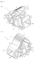
Fig. 1] Fig. 1 includes perspective views of a clamping device according to a first embodiment of the present invention. - [
Fig. 2] Fig. 2 is a side view of the clamping device (in an unclamped state). - [
Fig. 3] Fig. 3 is another side view of the clamping device (in a clamped state). - [
Fig. 4] Fig. 4 is yet another side view of the clamping device (with an interfering part interfering with an appropriate part). - [
Fig. 5] Fig. 5 is a schematic diagram of a medical circuit to which the clamping device is attached. - [
Fig. 6] Fig. 6 is a side view of a clamping device (in an unclamped state) according to a second embodiment of the present invention. - [
Fig. 7] Fig. 7 is another side view of the clamping device (in a clamped state). - [
Fig. 8] Fig. 8 is yet another side view of the clamping device (with an interfering part interfering with an appropriate part). - [
Fig. 9] Fig. 9 is a side view of a clamping device (in an unclamped state) according to a third embodiment of the present invention. - [
Fig. 10] Fig. 10 is another side view of the clamping device (in a clamped state). - [
Fig. 11] Fig. 11 is yet another side view of the clamping device (with an interfering part interfering with an appropriate). - Embodiments of the present invention will now be described specifically with reference to the drawings.
- A
clamping device 1 according to a first embodiment clamps a flexible tube and thus intercepts the flow of a fluid at the clamped position. As illustrated inFigs. 1 to 4 , theclamping device 1 basically includes a oneend portion 2 having afirst projection 2a, another end portion 3 having asecond projection 3a, and amiddle portion 4 continuous with the oneend portion 2 and with theother end portion 3. These portions are integrally formed of a predetermined resin (preferably, but not limited to, a thermoplastic resin moldable by extrusion (injection) molding or the like: for example, polypropylene, polyethylene, polyacetal, or the like). Theclamping device 1 illustrated inFigs. 1 and2 is in an unclamped state. Theclamping device 1 illustrated inFig. 3 is in a clamped state. - The one
end portion 2 includes thefirst projection 2a integrally formed on the inner surface (a surface facing the other end portion 3) thereof in such a manner as to project downward. The outer surface of the oneend portion 2 has irregularities for preventing fingers of the worker from slipping thereon during the clamping work. The oneend portion 2 further includes a lockedpart 5 provided at the tip thereof and being lockable by alocking part 6 to be described later. Theother end portion 3 includes thesecond projection 3a integrally formed at a position facing thefirst projection 2a, and thelocking part 6 integrally formed thereon and being capable of locking the lockedpart 5. - The
middle portion 4 is a portion that is continuous with the oneend portion 2 and with the other end portion 3 (a portion between the oneend portion 2 and the other end portion 3) and has one insertion hole H1 into which a flexible tube T is to be inserted. Meanwhile, theother end portion 3 includes a part extending substantially linearly from the middle portion 4 (a part having thesecond projection 3a), and a part standing therefrom while being bent (a part having the locking part 6). The standing part has an other insertion hole H2 into which the flexible tube T is to be inserted. - As illustrated in
Fig. 2 , when theclamping device 1 according to the first embodiment is in the unclamped state where the tip of the oneend portion 2 and the tip of theother end portion 3 are spaced apart from each other, the flexible tube T is inserted into the one insertion hole H1 and into the other insertion hole H2. Then, the oneend portion 2 is pressed in a direction α indicated inFig. 2 , whereby themiddle portion 4 is bent and the oneend portion 2 is brought closer to theother end portion 3. Accordingly, as illustrated inFig. 3 , thelocking part 6 locks the lockedpart 5, whereby the clamped state is established. In the clamped state, thefirst projection 2a and thesecond projection 3a are positioned close to each other and in combination clamp the flexible tube T extending through the insertion holes H1 and H2. Thus, the flow of the fluid can be intercepted at the clamped position. - In the clamped state illustrated in
Fig. 3 , when theother end portion 3 is bent in a direction β as indicated inFig. 3 , the lockedpart 5 locked by the lockingpart 6 is unlocked, whereby the unclamped state illustrated inFig. 2 can be established. That is, when the lockedpart 5 locked by the lockingpart 6 is unlocked, the tip of the oneend portion 2 and the tip of theother end portion 3 spontaneously move away from each other under the restoring force exerted by the resin material forming theclamping device 1. In the unclamped state, thefirst projection 2a and thesecond projection 3a are spaced apart from each other, and the clamping of the flexible tube T is disabled (the unclamped state). - The
clamping device 1 according to the first embodiment further includeswall portions 8 integrally formed at two respective side edges of theother end portion 3. Thewall portions 8 are a pair of wall-like members standing from the side edges of theother end portion 3 toward the oneend portion 2 and can prevent the flexible tube T extending through the insertion holes H1 and H2 from moving in the radial direction thereof (any directions orthogonal to the lengthwise direction). To avoid the interference of the oneend portion 2 with thewall portions 8 in the clamped state, the oneend portion 2 has cuts m at two respective side edges thereof. - The
wall portions 8 of theclamping device 1 according to the first embodiment have respective receivingparts 8a in the form of concave grooves that are open toward the oneend portion 2. In the state illustrated inFig. 3 where the lockedpart 5 is locked by the lockingpart 6 and the flexible tube T is thus clamped, the receivingparts 8a can receive respective fitting parts 2aa forming two respective end parts of thefirst projection 2a. That is, when the lockedpart 5 is locked by the lockingpart 6 and the fitting parts 2aa are fitted into the receivingparts 8a, thefirst projection 2a and thesecond projection 3a can be positioned relative to each other in the lengthwise direction of the flexible tube T. - The combination of the fitting parts 2aa and the receiving
parts 8a according to the first embodiment corresponds to "the positioning part" according to the present invention. In the state where the flexible tube T is clamped with the lockedpart 5 being locked by the lockingpart 6, the fitting parts 2aa and the receivingparts 8a can position thefirst projection 2a and thesecond projection 3a relative to each other in the lengthwise direction of the flexible tube T (i.e., a direction orthogonal to the direction in which thefirst projection 2a and thesecond projection 3a extend, or the lateral direction inFig. 3 ). - With the positioning part formed of the fitting parts 2aa and the receiving
parts 8a, the sealing area can be minimized while the leakage of the fluid that may occur at the time of clamping is prevented. Furthermore, the clamping can be easily disabled. In particular, the positioning part according to the first embodiment is formed of the fitting parts 2aa included in the oneend portion 2 and the receivingparts 8a included in theother end portion 3, and the fitting parts 2aa are fitted into the receivingparts 8a when the lockedpart 5 is locked by the lockingpart 6, whereby thefirst projection 2a and thesecond projection 3a can be positioned relative to each other. Thus, the relative positioning of thefirst projection 2a and thesecond projection 3a in the lengthwise direction of the flexible tube T can be performed more exactly. - Furthermore, with the
wall portions 8 standing from the side edges of theother end portion 3 and with the receivingparts 8a provided in thewall portions 8, the fitting into the receivingparts 8a can be performed more smoothly and more exactly. Thewall portions 8 may extend from the side edges of the oneend portion 2 toward theother end portion 3. In that case, the receiving parts in the form of concave grooves are provided in thewall portions 8, and the fitting parts to be fitted into the receiving parts are provided to theother end portion 3. - The pair of
wall portions 8 according to the first embodiment stand from the two respective side edges of the oneend portion 2 or theother end portion 3 and can guide the oneend portion 2 when the lockedpart 5 is locked by the lockingpart 6. Since theclamping device 1 according to the first embodiment includes the positioning part (the fitting parts 2aa and the receivingparts 8a) and thewall portions 8, not only the relative positioning of thefirst projection 2a and thesecond projection 3a in the lengthwise direction of the flexible tube T but also the guiding of the oneend portion 2 in the locking process can be implemented. - The
other end portion 3 according to the first embodiment includes interferingparts 7 integrally formed thereon. The interferingparts 7 are each a projection integrally provided on the inner side at the tip of theother end portion 3 and near the lockingpart 6. When the oneend portion 2 is further pressed in the direction α with the lockedpart 5 being locked by the locking part 6 (in the clamped state illustrated inFig. 3 ), the interferingparts 7 interfere with respective predetermined points P1 of the oneend portion 2 as illustrated inFig. 4 . Thus, the further movement of the lockedpart 5 can be prevented. The points with which the interferingparts 7 according to the first embodiment interfere are the two side edges at the tip of the oneend portion 2 and on the back side of the lockedpart 5. - As illustrated in
Fig. 5 , theclamping device 1 according to the first embodiment is attached to a blood circuit (a medical circuit) including an arterial blood circuit D1 and a venous blood circuit D2 for extracorporeally circulating the blood of a patient. Specifically, theclamping device 1 is connected to any of flow routes in the arterial blood circuit D1 and the venous blood circuit D2 and flow routes branching off therefrom and is capable of intercepting the flow of the blood that is under extracorporeal circulation, a physiological saline solution, or the like. InFig. 5 , theclamping device 1 is attached to each of a flow route branching off from the arterial blood circuit D1, and flow routes extending from a venous air-trap chamber f connected to the venous blood circuit D2. The clamping device may be attached to any position but to flexible tubes forming the medical circuit. - The arterial blood circuit D1 is provided at the distal end thereof with a shunt connector a to which an arterial puncture needle is attachable. The arterial blood circuit D1 is further provided with an arterial air-trap chamber e at a halfway point thereof and with a dialyzer connector c at the proximal end thereof. The dialyzer connector c is connectable to an arterial connector of a blood purifier (a dialyzer). The venous blood circuit D2 is provided at the distal end thereof with a shunt connector b to which a venous puncture needle is attachable. The venous blood circuit D2 is further provided with the venous air-trap chamber f at a halfway point thereof and with a dialyzer connector d at the proximal end thereof. The dialyzer connector d is connectable to a venous connector of the blood purifier (the dialyzer). Reference character B denotes a rubber button (a coinfusing member) that allows a drug or the like to be infused into the flexible tube or the blood or the like to be collected from the flexible tube.
- According to the first embodiment, the
other end portion 3 includes the interferingparts 7. Furthermore, when the oneend portion 2 is further pressed in the direction α with the lockedpart 5 being locked by the lockingpart 6, the interferingparts 7 interfere with the predetermined points P1 of the oneend portion 2 and can prevent the further movement of the lockedpart 5. Therefore, the lockedpart 5 can be prevented from being caught by an unintended part instead of the lockingpart 6 when the flexible tube T is clamped. Hence, the flexible tube can be clamped in a good manner without fail, and the flow of the fluid in the flexible tube can be intercepted more exactly. - The interfering
parts 7 according to the first embodiment are projections formed near the lockingpart 6 of theother end portion 3. When the oneend portion 2 is further pressed in the direction α with the lockedpart 5 being locked by the lockingpart 6, the projections interfere with the predetermined points P1 of the oneend portion 2. Since theother end portion 3 has such projections, the flexible tube can be clamped in a good manner without fail, and the flow of the fluid in the flexible tube T can be intercepted more exactly. Furthermore, as illustrated inFig. 5 , if theclamping device 1 according to the first embodiment is attached to a medical circuit, the medical circuit can exert the above advantageous effects exerted by theclamping device 1. - Now, a clamping device according to a second embodiment of the present invention will be described.
- As with the case of the first embodiment, a clamping device 1' according to the second embodiment clamps a flexible tube and thus intercepts the flow of a fluid at the clamped position. As illustrated in
Figs. 6 to 8 , the clamping device 1' basically includes the oneend portion 2 having thefirst projection 2a, theother end portion 3 having thesecond projection 3a, and themiddle portion 4 continuous with the oneend portion 2 and with theother end portion 3. These portions are integrally formed of a predetermined resin (preferably, but not limited to, a thermoplastic resin moldable by extrusion (injection) molding or the like: for example, polypropylene, polyethylene, polyacetal, or the like). The clamping device 1' illustrated inFig. 6 is in the unclamped state. The clamping device 1' illustrated inFig. 7 is in the clamped state. Elements that are the same as those employed in the first embodiment are denoted by respective ones of the corresponding reference numerals, and detailed description of such elements is omitted. - As illustrated in
Fig. 6 , when the clamping device 1' according to the second embodiment is in the unclamped state where the tip of the oneend portion 2 and the tip of theother end portion 3 are spaced apart from each other, the flexible tube T is inserted into the one insertion hole H1 and into the other insertion hole H2. Then, the oneend portion 2 is pressed in the direction α as indicated inFig. 6 , whereby themiddle portion 4 is bent and the oneend portion 2 is brought closer to theother end portion 3. Accordingly, as illustrated inFig. 7 , the lockingpart 6 locks the lockedpart 5, whereby the clamped state is established. Furthermore, in the clamped state illustrated inFig. 7 , when theother end portion 3 is bent in the direction β as indicated inFig. 7 , the lockedpart 5 locked by the lockingpart 6 is unlocked. Thus, the unclamped state illustrated inFig. 6 can be established. - The
other end portion 3 according to the second embodiment includes interferingparts 9 integrally formed thereon. The interferingparts 9 are each a projection (a wall-like projection) integrally provided on the inner side of theother end portion 3 and near thesecond projection 3a. When the oneend portion 2 is further pressed in the direction α with the lockedpart 5 being locked by the locking part 6 (in the clamped state illustrated inFig. 7 ), the tips of the interferingparts 9 interfere with the respective predetermined points P1 of the oneend portion 2 as illustrated inFig. 8 and can prevent the further movement of the lockedpart 5. The points with which the interferingparts 9 according to the second embodiment interfere are the two side edges at the tip of the oneend portion 2 and on the back side of the lockedpart 5. - According to the second embodiment, the
other end portion 3 includes the interferingparts 9. Furthermore, when the oneend portion 2 is further pressed in the direction α with the lockedpart 5 being locked by the lockingpart 6, the interferingparts 9 interfere with the predetermined points P1 of the oneend portion 2 and can prevent the further movement of the lockedpart 5. Therefore, the lockedpart 5 can be prevented from being caught by an unintended part instead of the lockingpart 6 when the flexible tube T is clamped. Hence, the flexible tube can be clamped in a good manner without fail, and the flow of the fluid in the flexible tube can be intercepted more exactly. - The interfering
parts 9 according to the second embodiment are projections formed near thesecond projection 3a of theother end portion 3. When the oneend portion 2 is further pressed in the direction α with the lockedpart 5 being locked by the lockingpart 6, the projections interfere with the predetermined points P1 of the oneend portion 2. Since theother end portion 3 has such projections, the flexible tube T can be clamped in a good manner without fail, and the flow of the fluid in the flexible tube can be intercepted more exactly. Furthermore, as illustrated inFig. 5 , if the clamping device 1' according to the second embodiment is attached to a medical circuit, the medical circuit can exert the above advantageous effects exerted by the clamping device 1'. - Now, a clamping device according to a third embodiment of the present invention will be described.
- As with the cases of the first and second embodiments, a
clamping device 1" according to the third embodiment clamps a flexible tube and thus intercepts the flow of a fluid at the clamped position. As illustrated inFigs. 9 to 11 , theclamping device 1" basically includes the oneend portion 2 having thefirst projection 2a, theother end portion 3 having thesecond projection 3a, and themiddle portion 4 continuous with the oneend portion 2 and with theother end portion 3. These portions are integrally formed of a predetermined resin (for example, polypropylene, olefinic resin, polyethylene, or the like). Theclamping device 1" illustrated inFig. 9 is in the unclamped state. Theclamping device 1" illustrated inFig. 10 is in the clamped state. Elements that are the same as those employed in the first embodiment are denoted by respective ones of the corresponding reference numerals, and detailed description of such elements is omitted. - As illustrated in
Fig. 9 , when theclamping device 1" according to the third embodiment is in the unclamped state where the tip of the oneend portion 2 and the tip of theother end portion 3 are spaced apart from each other, the flexible tube T is inserted into the one insertion hole H1 and into the other insertion hole H2. Then, the oneend portion 2 is pressed in the direction α as indicated inFig. 9 , whereby themiddle portion 4 is bent and the oneend portion 2 is brought closer to theother end portion 3. Accordingly, as illustrated inFig. 10 , the lockingpart 6 locks the lockedpart 5, whereby the clamped state is established. Furthermore, in the clamped state illustrated inFig. 10 , when theother end portion 3 is bent in the direction β as indicated inFig. 10 , the lockedpart 5 locked by the lockingpart 6 is unlocked. Thus, the unclamped state illustrated inFig. 9 can be established. - The one
end portion 2 according to the third embodiment includes an interferingpart 10 integrally formed thereon. The interferingpart 10 is a projection integrally provided at the tip of the oneend portion 2 and near the lockedpart 5. When the oneend portion 2 is further pressed in the direction α with the lockedpart 5 being locked by the locking part 6 (in the clamped state illustrated inFig. 10 ), the interferingpart 10 interferes with a predetermined point P2 of theother end portion 3 as illustrated inFig. 11 and can prevent the further movement of the lockedpart 5. The point with which the interferingpart 10 according to the third embodiment interferes is the tip of theother end portion 3 and on the side opposite the side having the lockingpart 6. - According to the third embodiment, the one
end portion 2 includes the interferingpart 10. Furthermore, when the oneend portion 2 is further pressed in the direction α with the lockedpart 5 being locked by the lockingpart 6, the interferingpart 10 interferes with the predetermined point P2 of theother end portion 3 and can prevent the further movement of the lockedpart 5. Therefore, the lockedpart 5 can be prevented from being caught by an unintended part instead of the lockingpart 6 when the flexible tube T is clamped. Hence, the flexible tube can be clamped in a good manner without fail, and the flow of the fluid in the flexible tube can be intercepted more exactly. - The interfering
part 10 according to the third embodiment is a projection formed near the lockedpart 5 of the oneend portion 2. When the oneend portion 2 is further pressed in the direction α with the lockedpart 5 being locked by the lockingpart 6, the projection interferes with the predetermined point P2 of theother end portion 3. Since the oneend portion 2 has such a projection, the flexible tube T can be clamped in a good manner without fail, and the flow of the fluid in the flexible tube can be intercepted more exactly. Furthermore, as illustrated inFig. 5 , if theclamping device 1" according to the third embodiment is attached to a medical circuit, the medical circuit can exert the above advantageous effects exerted by theclamping device 1". - In the third embodiment, as in the first embodiment, when the locked
part 5 is locked by the lockingpart 6 and the fitting parts 2aa are fitted into therespective receiving parts 8a, thefirst projection 2a and thesecond projection 3a can be positioned relative to each other in the lengthwise direction of the flexible tube T. With the positioning part formed of the fitting parts 2aa and the receivingparts 8a, the sealing area can be minimized while the leakage of the fluid that may occur at the time of clamping is prevented. Furthermore, the clamping can be easily disabled. - While some embodiments have been described above, the present invention is not limited thereto. For example, the
other end portion 3 may include nowall portions 8. Instead, the oneend portion 2 may include wall portions corresponding to thewall portions 8. Moreover, the position, the shape, and the length of projection of the lockingpart 6 and the position, the shape, and other factors of the lockedpart 5 may be set arbitrarily. Furthermore, the position, the shape, and other factors of each interfering part may be set arbitrarily. The medical circuit to which the clamping device according to the present invention is to be attached is not limited to a blood circuit and may be any of various medical circuits including flexible tubes. - The present invention is applicable to any clamping devices having different external shapes, any additional functions, and so forth, as long as the following holds true: the clamping devices each include the interfering part provided on the one end portion or on the other end portion; and when the one end portion is further pressed with the locked part being locked by the locking part, the interfering part interferes with an appropriate part and can prevent the further movement of the locked part.
-
- 1, 1', 1" clamping device
- 2 one end portion
- 2a first projection
- 2aa fitting part (positioning part)
- 3 other end portion
- 3a second projection
- 4 middle portion
- 5 locked part
- 6 locking part
- 7 interfering part
- 8 wall portion
- 8a receiving part (positioning part)
- 9 interfering part
- 10 interfering part
- T flexible tube
- H1, H2 insertion hole
Claims (5)
- A clamping device comprising:a one end portion having a first projection on an inner side and a locked part at a tip;an other end portion having a second projection at a position facing the first projection and a locking part capable of locking the locked part;a middle portion continuous with the one end portion and with the other end portion; andan insertion hole allowing a flexible tube to be inserted between the first projection and the second projection,wherein a clamped state where the locked part is locked by the locking part is established when the one end portion is pressed and is brought closer to the other end portion, and an unclamped state is established when the locked part locked by the locking part is unlocked by bending the other end portion, the clamping device being configured to clamp the flexible tube in the clamped state where the first projection and the second projection are positioned close to each other and to intercept a flow of a fluid at a clamped position; andwherein the one end portion or the other end portion has an interfering part, and when the one end portion is further pressed with the locked part being locked by the locking part, the interfering part interferes with an appropriate part and prevents further movement of the locked part.
- The clamping device according to Claim 1, wherein the interfering part is a projection provided on the other end portion and near the locking part, and when the one end portion is further pressed with the locked part being locked by the locking part, the projection interferes with a predetermined point of the one end portion.
- The clamping device according to Claim 1, wherein the interfering part is a projection provided on the one end portion and near the locked part, and when the one end portion is further pressed with the locked part being locked by the locking part, the projection interferes with a predetermined point of the other end portion.
- The clamping device according to any of Claims 1 to 3, further comprising a positioning part capable of positioning, in a state where the flexible tube is clamped with the locked part being locked by the locking part, the first projection and the second projection relative to each other in a lengthwise direction of the flexible tube.
- A medical circuit to which the clamping device according to any of Claims 1 to 4 is attached.
Applications Claiming Priority (2)
| Application Number | Priority Date | Filing Date | Title |
|---|---|---|---|
| JP2015018906 | 2015-02-03 | ||
| PCT/JP2016/053180 WO2016125820A1 (en) | 2015-02-03 | 2016-02-03 | Clamp device |
Publications (3)
| Publication Number | Publication Date |
|---|---|
| EP3254724A1 true EP3254724A1 (en) | 2017-12-13 |
| EP3254724A4 EP3254724A4 (en) | 2018-10-24 |
| EP3254724B1 EP3254724B1 (en) | 2023-08-23 |
Family
ID=56564160
Family Applications (1)
| Application Number | Title | Priority Date | Filing Date |
|---|---|---|---|
| EP16746651.5A Active EP3254724B1 (en) | 2015-02-03 | 2016-02-03 | Clamp device |
Country Status (5)
| Country | Link |
|---|---|
| US (1) | US10398836B2 (en) |
| EP (1) | EP3254724B1 (en) |
| JP (1) | JP6181286B2 (en) |
| CN (1) | CN107206227B (en) |
| WO (1) | WO2016125820A1 (en) |
Families Citing this family (13)
| Publication number | Priority date | Publication date | Assignee | Title |
|---|---|---|---|---|
| US9788667B2 (en) * | 2013-07-16 | 2017-10-17 | Fasteners For Retail, Inc. | Lock for securing front rail to wire shelving |
| JP5973669B2 (en) * | 2014-06-30 | 2016-08-23 | 日機装株式会社 | Clamping device for flexible tube |
| JP6706914B2 (en) | 2015-12-22 | 2020-06-10 | 日機装株式会社 | Clamp device |
| EP3405249B1 (en) * | 2015-12-24 | 2023-06-21 | Heriot Eyecare Pty. Ltd. | Pressure management device |
| CN107670145B (en) * | 2016-08-01 | 2021-09-14 | 北京唐颐惠康生物医学技术有限公司 | Infusion pump and infusion method special for stem cells |
| DE102017122647A1 (en) * | 2017-09-28 | 2019-03-28 | B. Braun Melsungen Ag | Hose clamp and volumetric pump with hose clamp |
| CN108159560B (en) * | 2017-12-18 | 2021-05-11 | 青岛市市立医院 | Screw gate valve for medical tube |
| US11020581B2 (en) * | 2018-10-04 | 2021-06-01 | Becton, Dickinson And Company | Pinch clamp |
| JP6783897B1 (en) * | 2019-05-09 | 2020-11-11 | 日機装株式会社 | Blood purification device |
| JP7569851B2 (en) * | 2020-05-11 | 2024-10-18 | テルモ株式会社 | Clamp |
| USD1083088S1 (en) * | 2023-03-04 | 2025-07-08 | Carolina Components Group, Inc. | Pinch clamp |
| USD1069569S1 (en) * | 2023-03-04 | 2025-04-08 | Carolina Components Group, Inc. | Pinch clamp |
| USD1124855S1 (en) | 2024-08-22 | 2026-05-05 | Ezbreezy Llc | Tool for air valves |
Family Cites Families (41)
| Publication number | Priority date | Publication date | Assignee | Title |
|---|---|---|---|---|
| US3419245A (en) | 1965-11-29 | 1968-12-31 | Vargas Mfg Co | Tube clamp |
| US3698681A (en) | 1970-12-15 | 1972-10-17 | Illinois Tool Works | On-off clamp for i. v. systems |
| US3822052A (en) | 1973-04-02 | 1974-07-02 | Illinois Tool Works | Shut off clamp |
| US3942228A (en) * | 1974-07-19 | 1976-03-09 | Buckman Thomas P | Tubing clamp |
| US4053135A (en) | 1976-09-20 | 1977-10-11 | Sigma Scientific Development, Inc. | Hose clamp |
| US4235412A (en) | 1978-10-30 | 1980-11-25 | Plastronics, Inc. | Tube clamping device |
| US4560378A (en) * | 1983-09-06 | 1985-12-24 | Weiland Mary C | Medical accessory |
| US4643389A (en) | 1984-12-27 | 1987-02-17 | American Hospital Supply Corporation | Tubing occlusion clip |
| US4589626A (en) | 1985-03-13 | 1986-05-20 | Bioresearch Inc. | Hose clamp |
| CH669117A5 (en) | 1985-06-24 | 1989-02-28 | Contempo Products | DEVICE FOR SEALING AND DISCONNECTING A HOSE, IN PARTICULAR A HOSE USED IN DIALYSIS OR INFUSION. |
| JPH024384A (en) | 1988-06-14 | 1990-01-09 | Terumo Corp | Clamp |
| US5035399A (en) * | 1990-05-25 | 1991-07-30 | C.R. Bard, Inc. | Protective tubing clamp apparatus |
| DE4118732A1 (en) | 1991-06-07 | 1992-12-10 | Joka Kathetertechnik Gmbh | HOSE CLAMP FOR MEDICAL PURPOSES |
| US5238218A (en) | 1992-07-15 | 1993-08-24 | Mackal Glenn H | Tube clamp |
| DE9310226U1 (en) | 1993-07-09 | 1993-09-30 | Spang & Brands GmbH, 61381 Friedrichsdorf | Hose clamp |
| US6113062A (en) * | 1999-01-28 | 2000-09-05 | Dsu Medical Corporation | Squeeze clamp |
| JP2001353215A (en) | 2000-06-13 | 2001-12-25 | Nikkiso Co Ltd | Medical Flexible Tube Clamping Device |
| US6592558B2 (en) | 2000-12-28 | 2003-07-15 | Baxter International Inc. | Clamp device, method and system for exchanging a solution |
| ATE480293T1 (en) * | 2002-01-31 | 2010-09-15 | Fenwal Inc | IRREVERSIBLY CLOSABLE CURRENT CONTROL TERMINAL |
| US8262639B2 (en) * | 2002-01-31 | 2012-09-11 | Fenwal, Inc. | Irreversible flow control clamp |
| JP2003235971A (en) * | 2002-02-19 | 2003-08-26 | Jms Co Ltd | Tube opening and closing clamp |
| US6698681B1 (en) | 2002-10-04 | 2004-03-02 | Kimberly-Clark Worldwide, Inc. | Apparatus and method for winding paper |
| US20040089828A1 (en) | 2002-10-18 | 2004-05-13 | Werth Albert A. | Conduit clamp |
| JP4137727B2 (en) * | 2003-07-07 | 2008-08-20 | 日機装株式会社 | Flexible tube clamping device |
| US7434779B2 (en) * | 2005-01-28 | 2008-10-14 | Twin Bay Medical, Inc. | Conduit clamp |
| US20070015658A1 (en) | 2005-07-15 | 2007-01-18 | Turaga Uday T | Fuzz reduction of sulfur sorbents |
| EP2007474B1 (en) * | 2006-04-05 | 2018-12-05 | Noble House Group Pty. Ltd. | Non-reopening locking pinch clamp for tubing |
| US7686279B2 (en) | 2006-05-12 | 2010-03-30 | Caridianbct, Inc. | Non-reopenable clamp for tubing sets |
| CN101352589B (en) * | 2007-06-21 | 2012-04-18 | 日本哈娜好医材株式会社 | Clamping device for an operation |
| FR2920513B1 (en) * | 2007-09-04 | 2021-05-28 | Fresenius Vial | CLAMP FOR SOFT TUBING, PUMP EQUIPPED WITH MEANS FOR OPENING SUCH CLAMP AND INFUSION SET EQUIPPED WITH SUCH CLAMP. |
| US20120232497A1 (en) * | 2009-09-23 | 2012-09-13 | Sukhvinder Singh | Pinch clamp |
| EP2332611B1 (en) | 2009-12-10 | 2020-06-17 | Fenwal, Inc. | Irreversible flow control clamp for flexible tubes |
| JP2012075520A (en) * | 2010-09-30 | 2012-04-19 | Nihon Covidien Kk | Tool for preventing incorrect operation of clamp |
| CN103391792B (en) * | 2011-02-17 | 2016-03-16 | 尼普洛株式会社 | Medical tube clamp |
| US20130031076A1 (en) * | 2011-07-28 | 2013-01-31 | Kikin, Inc. | Systems and methods for contextual searching of semantic entities |
| EP2780070B1 (en) * | 2011-11-16 | 2016-02-03 | Fresenius Vial SAS | Tube pump, tube clamp, perfusion set and system comprising a tube pump and a tube clamp |
| JP6069936B2 (en) * | 2012-08-01 | 2017-02-01 | 株式会社ジェイ・エム・エス | Infusion set |
| US9833606B2 (en) * | 2012-09-07 | 2017-12-05 | Fenwal, Inc. | Non-reopenable flow control clamp |
| JP5989231B2 (en) * | 2013-04-01 | 2016-09-07 | テルモ株式会社 | Clamp |
| WO2015064233A1 (en) * | 2013-10-29 | 2015-05-07 | ニプロ株式会社 | Clamp |
| CN104208808B (en) * | 2014-09-18 | 2016-08-24 | 河南科技大学第一附属医院 | A kind of infusion pipeline flow-stopping clip |
-
2016
- 2016-02-03 EP EP16746651.5A patent/EP3254724B1/en active Active
- 2016-02-03 CN CN201680008371.1A patent/CN107206227B/en active Active
- 2016-02-03 JP JP2016506712A patent/JP6181286B2/en active Active
- 2016-02-03 WO PCT/JP2016/053180 patent/WO2016125820A1/en not_active Ceased
-
2017
- 2017-08-01 US US15/665,635 patent/US10398836B2/en active Active
Also Published As
| Publication number | Publication date |
|---|---|
| JP6181286B2 (en) | 2017-08-16 |
| CN107206227A (en) | 2017-09-26 |
| US10398836B2 (en) | 2019-09-03 |
| EP3254724B1 (en) | 2023-08-23 |
| JPWO2016125820A1 (en) | 2017-04-27 |
| WO2016125820A1 (en) | 2016-08-11 |
| EP3254724A4 (en) | 2018-10-24 |
| US20170326294A1 (en) | 2017-11-16 |
| CN107206227B (en) | 2021-06-01 |
Similar Documents
| Publication | Publication Date | Title |
|---|---|---|
| EP3254724B1 (en) | Clamp device | |
| US10322278B2 (en) | Clamping device | |
| JP5973669B2 (en) | Clamping device for flexible tube | |
| US7682339B2 (en) | Indwelling needle device | |
| AU2016344420B2 (en) | Soft push tabs for catheter adapter | |
| US9775979B2 (en) | Male connector equipped with lock mechanism | |
| US9517327B2 (en) | Catheter-positioning slide cover clamp assembly | |
| WO2016052517A1 (en) | Extracorporeal circulation indwelling needle | |
| EP3421072A1 (en) | Safety catheter assembly | |
| WO2015147172A1 (en) | Indwelling needle for extracorporeal circulation | |
| EP2857059A1 (en) | Indwelling needle device | |
| JP3971654B2 (en) | Flexible tube clamping device | |
| US20160129225A1 (en) | Needle cover and winged needle with needle cover | |
| KR200488954Y1 (en) | Drainage set of medical suction unit | |
| JP4754049B2 (en) | Medical flexible tube clamping device | |
| JP2015000270A (en) | Indwelling needle for extracorporeal circulation |
Legal Events
| Date | Code | Title | Description |
|---|---|---|---|
| STAA | Information on the status of an ep patent application or granted ep patent |
Free format text: STATUS: THE INTERNATIONAL PUBLICATION HAS BEEN MADE |
|
| PUAI | Public reference made under article 153(3) epc to a published international application that has entered the european phase |
Free format text: ORIGINAL CODE: 0009012 |
|
| STAA | Information on the status of an ep patent application or granted ep patent |
Free format text: STATUS: REQUEST FOR EXAMINATION WAS MADE |
|
| 17P | Request for examination filed |
Effective date: 20170817 |
|
| AK | Designated contracting states |
Kind code of ref document: A1 Designated state(s): AL AT BE BG CH CY CZ DE DK EE ES FI FR GB GR HR HU IE IS IT LI LT LU LV MC MK MT NL NO PL PT RO RS SE SI SK SM TR |
|
| AX | Request for extension of the european patent |
Extension state: BA ME |
|
| DAV | Request for validation of the european patent (deleted) | ||
| DAX | Request for extension of the european patent (deleted) | ||
| A4 | Supplementary search report drawn up and despatched |
Effective date: 20180925 |
|
| RIC1 | Information provided on ipc code assigned before grant |
Ipc: A61M 39/28 20060101AFI20180919BHEP Ipc: F16B 2/24 20060101ALI20180919BHEP Ipc: F16B 2/10 20060101ALI20180919BHEP Ipc: F16L 33/02 20060101ALI20180919BHEP Ipc: A61M 5/168 20060101ALI20180919BHEP Ipc: F16B 2/22 20060101ALI20180919BHEP Ipc: A61M 1/14 20060101ALI20180919BHEP |
|
| REG | Reference to a national code |
Ref country code: DE Ref legal event code: R079 Ipc: A61M0001360000 Ref country code: DE Ref legal event code: R079 Ref document number: 602016082130 Country of ref document: DE Free format text: PREVIOUS MAIN CLASS: A61M0039280000 Ipc: A61M0001360000 |
|
| GRAP | Despatch of communication of intention to grant a patent |
Free format text: ORIGINAL CODE: EPIDOSNIGR1 |
|
| STAA | Information on the status of an ep patent application or granted ep patent |
Free format text: STATUS: GRANT OF PATENT IS INTENDED |
|
| RIC1 | Information provided on ipc code assigned before grant |
Ipc: F16B 2/10 20060101ALI20230329BHEP Ipc: A61M 39/28 20060101ALI20230329BHEP Ipc: A61M 5/168 20060101ALI20230329BHEP Ipc: A61M 1/14 20060101ALI20230329BHEP Ipc: A61M 1/36 20060101AFI20230329BHEP |
|
| INTG | Intention to grant announced |
Effective date: 20230418 |
|
| P01 | Opt-out of the competence of the unified patent court (upc) registered |
Effective date: 20230510 |
|
| GRAS | Grant fee paid |
Free format text: ORIGINAL CODE: EPIDOSNIGR3 |
|
| GRAA | (expected) grant |
Free format text: ORIGINAL CODE: 0009210 |
|
| STAA | Information on the status of an ep patent application or granted ep patent |
Free format text: STATUS: THE PATENT HAS BEEN GRANTED |
|
| AK | Designated contracting states |
Kind code of ref document: B1 Designated state(s): AL AT BE BG CH CY CZ DE DK EE ES FI FR GB GR HR HU IE IS IT LI LT LU LV MC MK MT NL NO PL PT RO RS SE SI SK SM TR |
|
| REG | Reference to a national code |
Ref country code: GB Ref legal event code: FG4D |
|
| REG | Reference to a national code |
Ref country code: CH Ref legal event code: EP |
|
| REG | Reference to a national code |
Ref country code: IE Ref legal event code: FG4D |
|
| REG | Reference to a national code |
Ref country code: DE Ref legal event code: R096 Ref document number: 602016082130 Country of ref document: DE |
|
| REG | Reference to a national code |
Ref country code: SE Ref legal event code: TRGR |
|
| REG | Reference to a national code |
Ref country code: LT Ref legal event code: MG9D |
|
| REG | Reference to a national code |
Ref country code: NL Ref legal event code: MP Effective date: 20230823 |
|
| REG | Reference to a national code |
Ref country code: AT Ref legal event code: MK05 Ref document number: 1601834 Country of ref document: AT Kind code of ref document: T Effective date: 20230823 |
|
| PG25 | Lapsed in a contracting state [announced via postgrant information from national office to epo] |
Ref country code: GR Free format text: LAPSE BECAUSE OF FAILURE TO SUBMIT A TRANSLATION OF THE DESCRIPTION OR TO PAY THE FEE WITHIN THE PRESCRIBED TIME-LIMIT Effective date: 20231124 |
|
| PG25 | Lapsed in a contracting state [announced via postgrant information from national office to epo] |
Ref country code: IS Free format text: LAPSE BECAUSE OF FAILURE TO SUBMIT A TRANSLATION OF THE DESCRIPTION OR TO PAY THE FEE WITHIN THE PRESCRIBED TIME-LIMIT Effective date: 20231223 |
|
| PG25 | Lapsed in a contracting state [announced via postgrant information from national office to epo] |
Ref country code: RS Free format text: LAPSE BECAUSE OF FAILURE TO SUBMIT A TRANSLATION OF THE DESCRIPTION OR TO PAY THE FEE WITHIN THE PRESCRIBED TIME-LIMIT Effective date: 20230823 Ref country code: PT Free format text: LAPSE BECAUSE OF FAILURE TO SUBMIT A TRANSLATION OF THE DESCRIPTION OR TO PAY THE FEE WITHIN THE PRESCRIBED TIME-LIMIT Effective date: 20231226 Ref country code: NO Free format text: LAPSE BECAUSE OF FAILURE TO SUBMIT A TRANSLATION OF THE DESCRIPTION OR TO PAY THE FEE WITHIN THE PRESCRIBED TIME-LIMIT Effective date: 20231123 Ref country code: NL Free format text: LAPSE BECAUSE OF FAILURE TO SUBMIT A TRANSLATION OF THE DESCRIPTION OR TO PAY THE FEE WITHIN THE PRESCRIBED TIME-LIMIT Effective date: 20230823 Ref country code: LV Free format text: LAPSE BECAUSE OF FAILURE TO SUBMIT A TRANSLATION OF THE DESCRIPTION OR TO PAY THE FEE WITHIN THE PRESCRIBED TIME-LIMIT Effective date: 20230823 Ref country code: LT Free format text: LAPSE BECAUSE OF FAILURE TO SUBMIT A TRANSLATION OF THE DESCRIPTION OR TO PAY THE FEE WITHIN THE PRESCRIBED TIME-LIMIT Effective date: 20230823 Ref country code: IS Free format text: LAPSE BECAUSE OF FAILURE TO SUBMIT A TRANSLATION OF THE DESCRIPTION OR TO PAY THE FEE WITHIN THE PRESCRIBED TIME-LIMIT Effective date: 20231223 Ref country code: HR Free format text: LAPSE BECAUSE OF FAILURE TO SUBMIT A TRANSLATION OF THE DESCRIPTION OR TO PAY THE FEE WITHIN THE PRESCRIBED TIME-LIMIT Effective date: 20230823 Ref country code: GR Free format text: LAPSE BECAUSE OF FAILURE TO SUBMIT A TRANSLATION OF THE DESCRIPTION OR TO PAY THE FEE WITHIN THE PRESCRIBED TIME-LIMIT Effective date: 20231124 Ref country code: FI Free format text: LAPSE BECAUSE OF FAILURE TO SUBMIT A TRANSLATION OF THE DESCRIPTION OR TO PAY THE FEE WITHIN THE PRESCRIBED TIME-LIMIT Effective date: 20230823 Ref country code: AT Free format text: LAPSE BECAUSE OF FAILURE TO SUBMIT A TRANSLATION OF THE DESCRIPTION OR TO PAY THE FEE WITHIN THE PRESCRIBED TIME-LIMIT Effective date: 20230823 |
|
| PG25 | Lapsed in a contracting state [announced via postgrant information from national office to epo] |
Ref country code: PL Free format text: LAPSE BECAUSE OF FAILURE TO SUBMIT A TRANSLATION OF THE DESCRIPTION OR TO PAY THE FEE WITHIN THE PRESCRIBED TIME-LIMIT Effective date: 20230823 |
|
| PG25 | Lapsed in a contracting state [announced via postgrant information from national office to epo] |
Ref country code: ES Free format text: LAPSE BECAUSE OF FAILURE TO SUBMIT A TRANSLATION OF THE DESCRIPTION OR TO PAY THE FEE WITHIN THE PRESCRIBED TIME-LIMIT Effective date: 20230823 |
|
| PG25 | Lapsed in a contracting state [announced via postgrant information from national office to epo] |
Ref country code: SM Free format text: LAPSE BECAUSE OF FAILURE TO SUBMIT A TRANSLATION OF THE DESCRIPTION OR TO PAY THE FEE WITHIN THE PRESCRIBED TIME-LIMIT Effective date: 20230823 Ref country code: RO Free format text: LAPSE BECAUSE OF FAILURE TO SUBMIT A TRANSLATION OF THE DESCRIPTION OR TO PAY THE FEE WITHIN THE PRESCRIBED TIME-LIMIT Effective date: 20230823 Ref country code: ES Free format text: LAPSE BECAUSE OF FAILURE TO SUBMIT A TRANSLATION OF THE DESCRIPTION OR TO PAY THE FEE WITHIN THE PRESCRIBED TIME-LIMIT Effective date: 20230823 Ref country code: EE Free format text: LAPSE BECAUSE OF FAILURE TO SUBMIT A TRANSLATION OF THE DESCRIPTION OR TO PAY THE FEE WITHIN THE PRESCRIBED TIME-LIMIT Effective date: 20230823 Ref country code: DK Free format text: LAPSE BECAUSE OF FAILURE TO SUBMIT A TRANSLATION OF THE DESCRIPTION OR TO PAY THE FEE WITHIN THE PRESCRIBED TIME-LIMIT Effective date: 20230823 Ref country code: CZ Free format text: LAPSE BECAUSE OF FAILURE TO SUBMIT A TRANSLATION OF THE DESCRIPTION OR TO PAY THE FEE WITHIN THE PRESCRIBED TIME-LIMIT Effective date: 20230823 Ref country code: SK Free format text: LAPSE BECAUSE OF FAILURE TO SUBMIT A TRANSLATION OF THE DESCRIPTION OR TO PAY THE FEE WITHIN THE PRESCRIBED TIME-LIMIT Effective date: 20230823 |
|
| REG | Reference to a national code |
Ref country code: DE Ref legal event code: R097 Ref document number: 602016082130 Country of ref document: DE |
|
| PLBE | No opposition filed within time limit |
Free format text: ORIGINAL CODE: 0009261 |
|
| STAA | Information on the status of an ep patent application or granted ep patent |
Free format text: STATUS: NO OPPOSITION FILED WITHIN TIME LIMIT |
|
| 26N | No opposition filed |
Effective date: 20240524 |
|
| PG25 | Lapsed in a contracting state [announced via postgrant information from national office to epo] |
Ref country code: SI Free format text: LAPSE BECAUSE OF FAILURE TO SUBMIT A TRANSLATION OF THE DESCRIPTION OR TO PAY THE FEE WITHIN THE PRESCRIBED TIME-LIMIT Effective date: 20230823 |
|
| PG25 | Lapsed in a contracting state [announced via postgrant information from national office to epo] |
Ref country code: MC Free format text: LAPSE BECAUSE OF FAILURE TO SUBMIT A TRANSLATION OF THE DESCRIPTION OR TO PAY THE FEE WITHIN THE PRESCRIBED TIME-LIMIT Effective date: 20230823 |
|
| REG | Reference to a national code |
Ref country code: CH Ref legal event code: PL |
|
| PG25 | Lapsed in a contracting state [announced via postgrant information from national office to epo] |
Ref country code: LU Free format text: LAPSE BECAUSE OF NON-PAYMENT OF DUE FEES Effective date: 20240203 |
|
| PG25 | Lapsed in a contracting state [announced via postgrant information from national office to epo] |
Ref country code: CH Free format text: LAPSE BECAUSE OF NON-PAYMENT OF DUE FEES Effective date: 20240229 |
|
| PG25 | Lapsed in a contracting state [announced via postgrant information from national office to epo] |
Ref country code: LU Free format text: LAPSE BECAUSE OF NON-PAYMENT OF DUE FEES Effective date: 20240203 Ref country code: CH Free format text: LAPSE BECAUSE OF NON-PAYMENT OF DUE FEES Effective date: 20240229 |
|
| PG25 | Lapsed in a contracting state [announced via postgrant information from national office to epo] |
Ref country code: BG Free format text: LAPSE BECAUSE OF FAILURE TO SUBMIT A TRANSLATION OF THE DESCRIPTION OR TO PAY THE FEE WITHIN THE PRESCRIBED TIME-LIMIT Effective date: 20230823 |
|
| PG25 | Lapsed in a contracting state [announced via postgrant information from national office to epo] |
Ref country code: BG Free format text: LAPSE BECAUSE OF FAILURE TO SUBMIT A TRANSLATION OF THE DESCRIPTION OR TO PAY THE FEE WITHIN THE PRESCRIBED TIME-LIMIT Effective date: 20230823 |
|
| REG | Reference to a national code |
Ref country code: BE Ref legal event code: MM Effective date: 20240229 |
|
| PG25 | Lapsed in a contracting state [announced via postgrant information from national office to epo] |
Ref country code: BE Free format text: LAPSE BECAUSE OF NON-PAYMENT OF DUE FEES Effective date: 20240229 |
|
| PG25 | Lapsed in a contracting state [announced via postgrant information from national office to epo] |
Ref country code: IE Free format text: LAPSE BECAUSE OF NON-PAYMENT OF DUE FEES Effective date: 20240203 |
|
| PG25 | Lapsed in a contracting state [announced via postgrant information from national office to epo] |
Ref country code: IE Free format text: LAPSE BECAUSE OF NON-PAYMENT OF DUE FEES Effective date: 20240203 Ref country code: BE Free format text: LAPSE BECAUSE OF NON-PAYMENT OF DUE FEES Effective date: 20240229 |
|
| PG25 | Lapsed in a contracting state [announced via postgrant information from national office to epo] |
Ref country code: CY Free format text: LAPSE BECAUSE OF FAILURE TO SUBMIT A TRANSLATION OF THE DESCRIPTION OR TO PAY THE FEE WITHIN THE PRESCRIBED TIME-LIMIT; INVALID AB INITIO Effective date: 20160203 |
|
| PG25 | Lapsed in a contracting state [announced via postgrant information from national office to epo] |
Ref country code: HU Free format text: LAPSE BECAUSE OF FAILURE TO SUBMIT A TRANSLATION OF THE DESCRIPTION OR TO PAY THE FEE WITHIN THE PRESCRIBED TIME-LIMIT; INVALID AB INITIO Effective date: 20160203 |
|
| PG25 | Lapsed in a contracting state [announced via postgrant information from national office to epo] |
Ref country code: TR Free format text: LAPSE BECAUSE OF FAILURE TO SUBMIT A TRANSLATION OF THE DESCRIPTION OR TO PAY THE FEE WITHIN THE PRESCRIBED TIME-LIMIT Effective date: 20230823 |
|
| PGFP | Annual fee paid to national office [announced via postgrant information from national office to epo] |
Ref country code: SE Payment date: 20260218 Year of fee payment: 11 |
|
| PGFP | Annual fee paid to national office [announced via postgrant information from national office to epo] |
Ref country code: GB Payment date: 20260219 Year of fee payment: 11 |
|
| PGFP | Annual fee paid to national office [announced via postgrant information from national office to epo] |
Ref country code: DE Payment date: 20260218 Year of fee payment: 11 |
|
| PGFP | Annual fee paid to national office [announced via postgrant information from national office to epo] |
Ref country code: IT Payment date: 20260224 Year of fee payment: 11 |
|
| PGFP | Annual fee paid to national office [announced via postgrant information from national office to epo] |
Ref country code: FR Payment date: 20260218 Year of fee payment: 11 |